US8801741B2 - Flat blade shielded obturator - Google Patents
Flat blade shielded obturatorDownload PDFInfo
- Publication number
- US8801741B2 US8801741B2US11/744,108US74410807AUS8801741B2US 8801741 B2US8801741 B2US 8801741B2US 74410807 AUS74410807 AUS 74410807AUS 8801741 B2US8801741 B2US 8801741B2
- Authority
- US
- United States
- Prior art keywords
- shaft
- switch
- obturator
- blade
- movable portion
- Prior art date
- Legal status (The legal status is an assumption and is not a legal conclusion. Google has not performed a legal analysis and makes no representation as to the accuracy of the status listed.)
- Active, expires
Links
- 230000006835compressionEffects0.000claimsdescription13
- 238000007906compressionMethods0.000claimsdescription13
- 210000003815abdominal wallAnatomy0.000description8
- 230000007246mechanismEffects0.000description4
- 230000004913activationEffects0.000description3
- 210000000683abdominal cavityAnatomy0.000description2
- 238000003780insertionMethods0.000description2
- 230000037431insertionEffects0.000description2
- 230000003993interactionEffects0.000description2
- 230000035515penetrationEffects0.000description2
- 208000005646PneumoperitoneumDiseases0.000description1
- 210000001015abdomenAnatomy0.000description1
- 230000009471actionEffects0.000description1
- 230000008901benefitEffects0.000description1
- 230000009849deactivationEffects0.000description1
- 238000002674endoscopic surgeryMethods0.000description1
- 238000002357laparoscopic surgeryMethods0.000description1
- 230000013011matingEffects0.000description1
- 230000004048modificationEffects0.000description1
- 238000012986modificationMethods0.000description1
- 230000000149penetrating effectEffects0.000description1
Images


Classifications
- A—HUMAN NECESSITIES
- A61—MEDICAL OR VETERINARY SCIENCE; HYGIENE
- A61B—DIAGNOSIS; SURGERY; IDENTIFICATION
- A61B17/00—Surgical instruments, devices or methods
- A61B17/34—Trocars; Puncturing needles
- A—HUMAN NECESSITIES
- A61—MEDICAL OR VETERINARY SCIENCE; HYGIENE
- A61B—DIAGNOSIS; SURGERY; IDENTIFICATION
- A61B17/00—Surgical instruments, devices or methods
- A61B17/34—Trocars; Puncturing needles
- A61B17/3417—Details of tips or shafts, e.g. grooves, expandable, bendable; Multiple coaxial sliding cannulas, e.g. for dilating
- A—HUMAN NECESSITIES
- A61—MEDICAL OR VETERINARY SCIENCE; HYGIENE
- A61B—DIAGNOSIS; SURGERY; IDENTIFICATION
- A61B17/00—Surgical instruments, devices or methods
- A61B17/34—Trocars; Puncturing needles
- A61B17/3494—Trocars; Puncturing needles with safety means for protection against accidental cutting or pricking, e.g. limiting insertion depth, pressure sensors
- A61B17/3496—Protecting sleeves or inner probes; Retractable tips
Definitions
- This inventionrelates generally to trocars or access ports used in endoscopic or laparoscopic surgeries and more particularly, to flat blade shielded obturators.
- a surgical access port or trocargenerally has a cannula and a valve housing coupled to one end of the cannula and an obturator inserted into the cannula has a shaft with a sharp blade or tip at one end of the shaft.
- the trocar cannulaextends across a body wall, e.g., the abdominal wall, providing access into a body cavity, such as the abdominal cavity.
- the obturatorfacilitates the placement of the trocar by puncturing and/or penetrating the tissue forming the body wall.
- the obturatoris inserted through the cannula and its sharp bladed tip extends beyond one end of the cannula.
- the sharp bladed tip of the obturatorcuts tissue as the trocar and obturator are moved through the body wall. Once the trocar and obturator are operatively positioned, the obturator can be removed from the trocar body leaving the cannula to provide working-channel access into the body cavity.
- a spring-loaded tubular safety shieldwhich surrounds the shaft of the obturator may move forward to cover the tip of the obturator once resistance to the movement of the safety shield, e.g., from the body wall, is removed. As such, the cutting stops once the body wall has been penetrated.
- a relatively large forcemay be required to cause the tip of an obturator to penetrate the body wall. Once the tip penetrates the body wall, resistance to penetration is removed and the tip of the obturator is suddenly free to reach into the body cavity and cause additional cutting. Failure to stop this cutting action can result in complications.
- Obturators having spring-loaded tubular safety shieldsmay require larger incisions and may require considerable time to move the shield to cover the tip, the shield possessing a relatively large mass.
- an obturatorcomprises a handle and a shaft.
- the handlehas a rotatable switch arranged to rotate about a rotational axis from a first position to a second position.
- the shaftis connected to the handle and has a longitudinal axis parallel with the rotational axis.
- the shafthas a movable portion and a fixed portion with a blade connected to the fixed portion of the shaft.
- the rotatable switch in the first positionobstructs the movable portion of the shaft to prevent movement of the movable portion of the shaft along the longitudinal axis and in the second position frees the movable portion of the shaft to allow movement of the movable portion of the shaft along the longitudinal axis.
- an obturatorcomprises a handle and a shaft.
- the handlehas a manually engagable switch arranged to rotate about a rotational axis from a first position to a second position.
- the shaftis connected to the handle and has a longitudinal axis parallel with the rotational axis.
- the shafthas a movable portion and a fixed portion with a blade connected to the fixed portion of the shaft.
- the switchhas means for aligning with the movable portion of the shaft to prevent movement of the movable portion of the shaft along the longitudinal axis and having means for misaligning with the shaft to allow movement of the movable portion of the shaft.
- an obutratorcomprises a handle and a shaft.
- the handlehas a manually engagable switch arranged to rotate about a rotational axis from a first position to a second position.
- the shaftis connected to the handle and has a longitudinal axis parallel with the rotational axis, the shaft having a movable shield and a fixed shield with a blade connected to the fixed shield.
- the switchhas a planar surface and a slot. The planar surface of the switch being aligned with the shaft prevents movement of the movable shield along the longitudinal axis. The slot of the switch being aligned with the shaft allows movement of the movable shield.
- FIG. 1is a perspective view of a trocar system with a shielded bladed obturator in accordance with various aspects of the present invention
- FIG. 2is a side view of a shielded bladed obturator in accordance with various aspects of the present invention
- FIG. 3is an exploded view of a shielded bladed obturator in accordance with various aspects of the present invention
- FIG. 4is a side view of a shielded bladed obturator in accordance with various aspects of the present invention.
- FIG. 5is a top view of a shielded bladed obturator with a cover removed/hidden in accordance with various aspects of the present invention
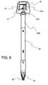
- FIG. 6is a side view of a shielded bladed obturator in accordance with various aspects of the present invention.
- FIG. 7is a top view of a shielded bladed obturator with a cover removed/hidden in accordance with various aspects of the present invention.
- FIG. 8is a perspective view of a shielded bladed obturator with a cover removed/hidden in accordance with various aspects of the present invention.
- FIG. 9is a side view of a shielded bladed obturator in accordance with various aspects of the present invention.
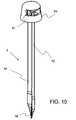
- FIG. 10is a perspective view of a shielded bladed obturator in accordance with various aspects of the present invention.
- FIG. 11is an exploded view of a shielded bladed obturator in accordance with various aspects of the present invention.
- FIG. 12is a perspective view of a shielded bladed obturator with a cover removed/hidden in accordance with various aspects of the present invention.
- FIG. 13is a side view of a shielded bladed obturator in accordance with various aspects of the present invention.
- FIG. 14is a perspective view of a shielded bladed obturator with a cover removed/hidden in accordance with various aspects of the present invention.
- FIG. 15is a top view of a shielded bladed obturator with a cover removed/hidden in accordance with various aspects of the present invention.
- FIG. 16is a perspective view of a shielded bladed obturator with a cover removed/hidden in accordance with various aspects of the present invention
- FIGS. 17-18are top views of a shielded bladed obturator with a cover removed/hidden in accordance with various aspects of the present invention.
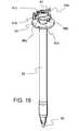
- FIG. 19is a perspective view of a shielded bladed obturator in accordance with various aspects of the present invention.
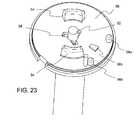
- FIGS. 20-23are perspective views of a shielded bladed obturator with various components removed/hidden in accordance with various aspects of the present invention.
- FIG. 24is a cross-sectional side view of a shielded bladed obturator in accordance with various aspects of the present invention.
- FIG. 25is a perspective view of a shielded bladed obturator with various components removed/hidden in accordance with various aspects of the present invention.
- FIG. 26is a cross-sectional side view of a shielded bladed obturator in accordance with various aspects of the present invention.
- FIG. 27is a top view of a shielded bladed obturator with various components removed/hidden in accordance with various aspects of the present invention.
- FIG. 28is a perspective view of a shielded bladed obturator with various components removed/hidden in accordance with various aspects of the present invention.
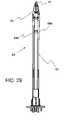
- FIGS. 29-31are side views of a shielded bladed obturator with various components removed/hidden in accordance with various aspects of the present invention.
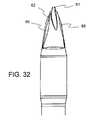
- FIG. 32is a side view of a shielded bladed obturator in accordance with various aspects of the present invention.
- FIG. 33is a side view of a shielded bladed obturator with various components removed/hidden in accordance with various aspects of the present invention.
- FIGS. 34-36are side views of a shielded bladed obturator in accordance with various aspects of the present invention.
- FIG. 37is a side view of a shielded bladed obturator with various components removed/hidden in accordance with various aspects of the present invention.
- FIG. 38is a side view of a shielded bladed obturator with various components removed/hidden in accordance with various aspects of the present invention.
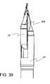
- FIG. 39is a side view of a shielded bladed obturator in accordance with various aspects of the present invention.
- FIG. 40is a side view of a shielded bladed obturator with various components removed/hidden in accordance with various aspects of the present invention.
- FIG. 41is a side view of a shielded bladed obturator in accordance with various aspects of the present invention.
- FIGS. 42-43are side views of a shielded bladed obturator with various components removed/hidden in accordance with various aspects of the present invention.
- FIG. 44is a side view of a shielded bladed obturator in accordance with various aspects of the present invention.
- an obturatorhaving a handle and a shaft.
- the handleis on a proximal end of the shaft and a sharp bladed tip coupled on the other (distal) end of the shaft.
- the distal end of an obturatoris configured to minimize the insertion force.
- the obturatoris also configured to provide control that is maintained during entry.
- the obturatoralso has a shield that protects the blade before use and covers the blade as it is passes through the abdominal wall.
- the shieldis a single monolithic piece shielding the blade or at least one section or components situated to protect or cover the blade.
- FIG. 1a trocar with an obturator 3 inserted into a cannula 5 is shown.
- the obturator 3has a handle 31 , shield 33 and a blade 35 .
- a housing 7is attached to the proximal end of the cannula 51 .
- the trocar cannula 5provides surgical instrument access into the body cavity with the obturator 3 removed.
- the trocar housing 7 releasbly attached to the trocar cannula 51contains one or more trocar seals to maintain pneumoperitoneum when the obturator and/or surgical instruments are inserted through and withdrawn from the trocar 5 .
- the obturator handle 31includes a cover 45 with a switch 41 .
- the switch 41is generally circular and arranged to rotate around the longitudinal axis of the obturator 3 .
- the switchhas a lever 41 a .
- the leverprotrudes through an opening of the periphery of the cover 45 allowing the lever 41 a to be accessible by a user, e.g., a surgeon.
- a spring 43such as an extension, leaf or the like, is attached on one end to the switch 41 , e.g., post 41 b .
- the other end of the springis attached to a projection 53 a extending from a base plate 53 .
- the switch 41 and cover 45are mounted on the base plate 53 , securing the switch 41 between the cover 45 and base plate 53 .
- Extending away from the base plate and cover along the longitudinal axis of the obturatoris an outer shaft 53 b .
- the outer shaft 53 bis tubular having a lumen through which an inner shaft 51 extends there through.
- a projection or flange 51 aextends from the proximal end of the inner shaft orthogonally from the longitudinal axis of the inner shaft 51 .
- the flange 51 aprevents the inner shaft 51 from completely extending through the lumen of the outer shaft 53 b .
- the inner shaft 51slides relative to the outer shaft 53 b and is attached to a blade shield 33 .
- the blade shieldis also moveable, e.g., sliding as the shaft 51 slides.
- the inner shaft 51 and the blade shield 33are integral and/or monolithically formed.
- a compression spring 55surrounds a portion of the inner shaft 51 and biases the inner shaft 51 and blade shield 33 distally. Both the compression spring 55 and a portion of the inner shaft 51 are housed within a fixed shield 57 that is generally tubular.
- One end of the fixed shield 57is connected to the outer shaft 53 b and the other end has one or more projections that extend through a slot in the blade 35 securing the blade 35 to the fixed shield 57 .
- a projection or hookextends from the blade shield and through the slot 35 a in the blade 35 . In one aspect, the hook is situated and slidable between two projections extending from the fixed shield 57 along the slot 35 a of the blade 35 .
- the other end of the blade shield 33is connected to the inner shaft 51 .
- the blade shield 33 and the inner shaft 51have corresponding projections and slots to secure the inner shaft to the blade shield 33 .
- the blade shield 33abuts one end of the compression spring 55 .
- the other end of the compression spring 55abuts the outer shaft 53 b .
- the compression spring 55biases the blade shield 33 forward covering one side of the blade 35 .
- An example of an asymmetrical blade shield configurationis described in U.S. Pat. No. 5,916,232, the disclosure of which is incorporated by reference as if set forth in full herein.
- a sharp bladed tip of an obturatorcan comprise of a blade having a symmetrical triangular form. This blade configuration can tend to form an opening, which results in a wound having three cuts each radiating from a central puncture or penetration point.
- Single blade obturatorspenetrate the body wall through a single incision.
- a leveris coupled to the handle of the obturator that is manually actuated to unlock the shield (which protects the cutting blade when not in use).
- An extension springis used that is connected between the rotating lever switch and the fixed shaft. The spring holds the lever biased to one side. As the lever is rotated, the spring is pulled over the centerline of the obturator and pulls the lever to the other side. At this location, the shield is unlocked.
- the cam shaft of the shieldslides up and the blades become exposed for cutting.
- the other end of the cam shaftpushes on a cam surface which is part of the lever switch causing the switch to rotate back towards its original position.
- the extension springis pulled back over the centerline, pulling it in the opposite direction.
- the switch 41 that is coupled to the inner shaft 51 that is coupled to the blade shield 33controls or regulates the arming/disarming or unlocking/locking of the blade shield 33 , e.g., allowing the blade shield 33 to slidably retract back towards a proximal direction. Initially, the switch 41 is in the armed or locked position, such that the blade shield 33 is locked or prevented from retracting to expose the blade 35 for cutting.
- the switch 41 in the armed positionis situated to block movement of the inner shaft 51 .
- an outer surface or edge of the switch 41abuts or is in contact with a ledge or projection of the inner shaft 51 extending laterally from the longitudinal axis of the inner shaft.
- the interaction of the switch 41 with the inner shaft 51controls the activation or deactivation of the blade shield 33 .
- the cover 45prevents further movement of the switch by limiting the longitudinal movement of the switch 41 and also adds stability to the switch 41 .
- the extension spring 43 coupled to the switch 41biases the switch towards the initial or armed position.
- the extension spring 43generally extends to an over center condition at the initial or armed position of the switch 41 , e.g., more towards one portion or half of the switch or base plate 53 . As such, the extension spring 43 in the locked position tends to pull the switch 41 towards a clockwise direction.
- the switch 41 via the lever 41 ais manually actuated to move or rotate from the armed position to the disarmed or unlocked position.
- the switch 41is rotated in a counter-clockwise direction.
- the extension spring 43is moved from over center at the initial/locked position towards an over center position at the unlocked position, e.g., more towards an opposing portion or half of the switch 41 or base plate 53 .
- the extension spring 43 in the unlocked portion or positiontends to pull the switch 41 towards a counter-clockwise direction.
- Such manual actuationovercomes the biasing force of the extension spring 43 that tends to drive the switch towards the armed position.
- the switch 41moves back to the armed position.
- the switch 41returns back to its starting position.
- the ledge 51 a of the inner shaft 51abuts the slanted surface or slot 47 of the switch 41 thereby preventing further rotational movement of the switch 41 backed to the armed position.
- the switch 41when in or moved into the disarmed position, engages a projection or slot on the base plate 53 to maintain the switch in the unlock position.
- the lever 45when in the disarmed position, recedes within the cover or within a slot or cavity in the cover thereby hiding and preventing inadvertent or undesired activation of the lever to re-lock the blade shield.
- the inner shaft 51 and the blade shield 33are allowed to retract largely unobstructed by the switch 41 .
- the ledge 42 of switch 41does not abut the ledge 51 a extending from the inner shaft 51 , such that the inner shaft is prevented from traveling longitudinally.
- Rotational movement of the switch to the disarmed positionpositions a cavity or a slanted cam slot 47 over the ledge 51 a of the inner shaft 51 .
- the inner shaft 51is provided a longitudinal path through the switch 41 and as pressure or force is applied to the blade shield 33 , the blade shield can retract causing the inner shaft 51 to retract.
- the retracting blade shield 33exposes blade 35 thereby allowing the surgeon to cut tissue with the blade 35 .
- the compression spring 55 coupled to the blade shield 33 and inner shaft 51resists the retraction movement and facilitates forward movement of the blade to enhance the speed to re-cover the exposed blade 35 .
- the blade shield 33moves forward.
- the inner shaft 51forces or moves the switch 41 towards the armed or locked position.
- the switch 41With the ledge 51 a of the inner shaft retracting or moving longitudinally along the slanted surface 47 in the cavity or notch in the switch 41 , the switch 41 is forced to rotate towards the armed position, e.g., clockwise.
- the extension spring 43moves over center, the extension spring 43 biases the switch 41 towards the armed or locked position.
- the blade shield 33 and inner shaft 51move forward.
- the obturator 3has a switch 91 that obstructs movement of a cam shaft 92 that acts as a blade shield preventing exposure of blade 35 for cutting.
- a cover 93secures the switch 91 to the base plate 53 of the fixed shaft 94 of the obturator.
- An extension spring 97connects the switch to the base plate 53 and biases the switch to the locked position obstructing retraction of the cam shaft 92 .
- a middle pin 95 coupled with a compression spring 96connects the switch 91 to the cam shaft 92 and biases the cam shaft to cover or prevent exposure of the blade 36 for cutting.
- a lever 51 b extending from the switch 91 through a slot in the cover 93allows manipulation of the switch 91 .
- the switch in the locked or armed positionhas an edge or flange 91 a interacting with an edge or flange 92 a thereby obstructing and preventing retraction of the cam shaft 92 .
- the extension spring 97produces a force that generates a moment about the centroid of the switch 91 , such that the moment forces the switch to rotate towards the unlocked position, e.g., counter-clockwise.
- the interaction with the ramped cam surface 98 a abutting the flange 92 a of the cam shaft 92limits further rotation of the switch 91 .
- the cam shaft 92could comprises of multiple component having a distal portion or component for contacting tissue and a proximal portion or component interacting with the switch 91 .
- cam shaft 92Pressure or force on the cam shaft 92 causes the cam shaft 92 to retract and exposes the blade 35 for cutting.
- the cam shaft 92retracts, the flange 92 a of the cam shaft 92 travels along the cam surface 98 a and thereby forces the switch 91 to rotate towards the locked position, e.g., clockwise.
- the extension spring 97 connected to the switch 91also rotates towards the locked position. In one aspect, the switch 91 rotates about 180 degrees from the unlocked position back to the locked position.
- the extension spring 97When the switch 91 has rotated about 120 degrees or such that the extension spring 97 is on an opposing side of the centroid relative to the unlocked position of the switch 91 , the extension spring 97 generates a moment that forces the switch to rotate towards the locked position, e.g., clockwise.
- the flange 92 a of the cam shaft 92 engaged with an opposing surface 98 b of the switch 91limits completion of the rotation of the switch 91 to the locked position.
- the cam shaft 92moves forward due to removal of pressure or force on the cam shaft 92 and through assistance of the compression spring, the flange 92 a clears the surface 98 b of the switch 91 .
- the switch 91unobstructed completes the rotation towards the locked position.
- the flange 91 aagain obstructs the flange 92 a of cam shaft 92 preventing retraction of the cam shaft 92 and thus exposure of the blade 35 for cutting.
- an arming or lockout mechanismis provided to prevent inadvertent exposure of the blades.
- a leveris coupled to the handle of the obturator. The lever is manually actuated to unlock the shield that protects the cutting blade.
- a keywaywhich when rotated, aligns with the keys on the generally center shield shaft of the obturator.
- the obturatoris pushed into the abdominal wall causing the shield to retract or pushed up.
- the opposite end that has the keytrips the lever, causing the lever to prepare to reset.
- the shieldmoves forward protecting the blade and the lever resets itself to lock the shield.
- a handle 21 of a flat blade shielded obturatorhas a cover 23 and a switch 25 with a lever 27 extending from the switch.
- the switch 25rests on base plate 56 from which outer shaft 53 b extends.
- a compression spring 29is placed between the cover 23 and the switch 25 biasing the switch 25 into position against the base plate 56 .
- the connection between the switch 25 and cover 23 in one aspectis facilitated by tracks, detents or slots outlined on the switch 25 and/or cover 23 .
- the spring 29is coaxial with the longitudinal axis of the obturator and inner shaft 52 .
- the inner shaft 52is movable through an opening in the switch 25 .
- the switch 25also has one or more slots allowing and delimiting the rotation of the switch 25 and slidably connecting the slots 26 to projections 54 of base plate 56 .
- the return springis an extension spring 28 a that is connected to a post on the switch 25 and a post on the base plate 56 .
- the return springis a flat spring 28 b that is connected to a flange on the switch 25 and to one of the projections 54 of base plate 56 .
- a lever stop post 56 a extending from the base plate 56limits the rotation of the switch 25 as the switch is biased towards the locked position.
- Another lever stop post 56 b extending from the base plate 56delimits the unlocked position and limits the rotation of the switch 25 as the switch is moved towards the unlocked position.
- a lever lock ramp 56 cextending from the base plate 56 engages a mating slot in the switch holding the switch in the unlocked position.
- the inner shaft 52has one or more keys 58 extending radially from the inner shaft.
- the one or more keys 58are arranged to slide pass keyways in the base plate 56 .
- Corresponding keyways 22are situated in the switch 25 .
- the keyways 22are not aligned to the keys 58 of the inner shaft 52 when the switch 25 is in the locked position, thereby preventing longitudinal movement or retraction of the inner shaft 52 and thus the blade shield 33 .
- the userthrough manipulation of the lever 27 extending from the switch 25 rotates the switch to the disarmed or unlocked position thereby aligning the keyways 22 on switch 25 to be aligned to the keys 58 on the inner shaft 52 .
- the inner shaft 52is unobstructed and thereby allowed to retract to expose the blade 35 for cutting.
- the keys 58also move out of the keyways 22 of the switch 25 .
- the switchmoves to the locked position.
- the switch 25once again obstructs the path of the inner shaft 51 thereby locking or preventing movement of the blade shield 33 to expose the blade 35 for cutting.
- a pinprotrudes through the center of the shield.
- the center pinis connected to individual blades by a cam assembly.
- the bladesare locked to the shield by a pivot point.
- the center pinis moved up into the shield.
- the bladesWith the center pin connected to the blades by a cam assembly, the blades are extended out of the shield, to expose them. The blades remain exposed outside the shield as long as there is force on the center pin.
- forceis removed or reduced from the center pin, e.g., when the pin is through the abdominal wall, the center pin is allowed to reset to its initial position and cause the blades to retract.
- the obturator as suchdoes not rely on friction to push or hold a shield back to expose the blades.
- Force at the tip of the obturatore.g., on the center pin
- an obturator 3has a movable center pin 61 .
- the center pin 61slides forward and retracts back relative to a shaft 63 of the obturator 3 .
- the center pin 61extends from a movable shaft that is slides within a lumen of fixed inner shaft.
- the fixed inner shaftis encased or incorporated into an outer shaft.
- a flange or enlarged end 68 a,b of the center pin 61 engaging with a flange or enlarged end 69 a,b of the shaft 63limits retraction of the pin 61 .
- the pin 61is largely encompassed or encased in the shaft 63 .
- An aperture 62 in the tip of the shaft 63allows passage of the pin 61 . Also, a pair of opposing slots in the tip of shaft 63 allows passage of opposing pivoting blades 65 .
- the blades 65pivot on pivot pins 64 connected to the shaft 63 .
- One or more projections 67 extending from the center pin 61interact with cam slots 66 in pivoting blades 65 .
- Force or pressure on the center pin 61retracts the center pin thereby engaging the cam slots 66 of the blades 65 to cause the blades to pivot and be exposed, e.g., displayed outside the shaft via slots in the shaft 63 .
- a spring coupled to the pinbiases the pin forward causing the blades to retract.
- the slots 66 in the blades 65 amay be further angled or curved to vary, regulate or control the speed and/or time of the blades' exposure.
- the blades 65 or cam slots 66 in the blades 65may be angled to expose a portion of the blade, e.g., the tips or distal portions, while covering the remaining portion of the blade to enhance cutting of the tissue or increasing covering of the blade after use.
- the size and/or shape of the center pin 61 ais enlarged or curved to regulate or control the speed and/or time of the blades' exposure.
- the tip or end of the obturatoracts as the center pin 61 a .
- An enlarged endincreases the contact surface area of the center pin 61 a providing quicker and/or less precise activation to deploy the blades 65 a .
- Channels within the center pin 61 a and the shaft 63 aallow the range of movement of the pivoting blades 65 a.
- a movable portion of the shafte.g., the blade shield 33
- the blades 65 bpivot on pivot pins 83 connected to the fixed shaft.
- the pivot pins and corresponding slots in the blades 65 bhave barbs or teeth further securing the blades to the blade shield 33 .
- Force or pressure on the blade shield 33retracts the blade shield thereby engaging the cam slots of the blades to cause the blades to pivot and be exposed, e.g., displayed outside the shaft.
- the compression spring coupled to the blade shield 33biases the blade shield 33 forward causing the blades to retract or pivot closed.
- the center pin 61 b and single blade 65 care connected by a linkage 70 .
- the linkagein one aspect, is rotationally attached to a shaft 75 of the obturator via a pin or post 74 .
- the post 74extends through a slot 76 in the center pin 61 b .
- a pivot plate 71is also connected to the post 74 with the post 74 acting as a pivot point for the plate 71 . Channels within the center pin 61 b and the shaft 75 allow the range of movement of the pivot plate 71 .
- Pin 72 ais connected to the center pin 61 b and extends through a cam slot 71 a on plate 71 .
- Pin 72 bis connected to the blade 65 c and extends through a cam slot 71 b on plate 71 .
- the pin 72 aengages the cam slot 71 a of the plate 71 causing the plate 71 to rotate about the post 74 .
- the cam slot 71 bengages the pin 72 b causing the blade 72 b to advance or move in the opposite direction of the center pin 61 b thereby exposing the blade 65 c for cutting.
- retractable blade mechanisms described abovemay be used in conjunction with the previously described arming or locking shield mechanisms.
- a switch in the locked positioncan prevent retraction of a center pin thereby preventing the extension or pivoting of the blade or blades.
- the present inventionprovides a bladed shielded obturator.
Landscapes
- Health & Medical Sciences (AREA)
- Surgery (AREA)
- Life Sciences & Earth Sciences (AREA)
- Biomedical Technology (AREA)
- Nuclear Medicine, Radiotherapy & Molecular Imaging (AREA)
- Engineering & Computer Science (AREA)
- Pathology (AREA)
- Heart & Thoracic Surgery (AREA)
- Medical Informatics (AREA)
- Molecular Biology (AREA)
- Animal Behavior & Ethology (AREA)
- General Health & Medical Sciences (AREA)
- Public Health (AREA)
- Veterinary Medicine (AREA)
- Surgical Instruments (AREA)
Abstract
Description
Claims (18)
Priority Applications (4)
| Application Number | Priority Date | Filing Date | Title |
|---|---|---|---|
| US11/744,108US8801741B2 (en) | 2006-05-03 | 2007-05-03 | Flat blade shielded obturator |
| US12/106,227US8657843B2 (en) | 2006-05-03 | 2008-04-18 | Shield lockout for bladed obturator and trocars |
| PCT/US2008/060928WO2008131299A1 (en) | 2007-04-18 | 2008-04-18 | Shield lockout for bladed obturator and trocars |
| US14/188,243US9474548B2 (en) | 2006-05-03 | 2014-02-24 | Shield lockout for bladed obturator and trocars |
Applications Claiming Priority (4)
| Application Number | Priority Date | Filing Date | Title |
|---|---|---|---|
| US74631306P | 2006-05-03 | 2006-05-03 | |
| US91267907P | 2007-04-18 | 2007-04-18 | |
| US91554507P | 2007-05-02 | 2007-05-02 | |
| US11/744,108US8801741B2 (en) | 2006-05-03 | 2007-05-03 | Flat blade shielded obturator |
Related Child Applications (1)
| Application Number | Title | Priority Date | Filing Date |
|---|---|---|---|
| US12/106,227Continuation-In-PartUS8657843B2 (en) | 2006-05-03 | 2008-04-18 | Shield lockout for bladed obturator and trocars |
Publications (2)
| Publication Number | Publication Date |
|---|---|
| US20070260275A1 US20070260275A1 (en) | 2007-11-08 |
| US8801741B2true US8801741B2 (en) | 2014-08-12 |
Family
ID=39875937
Family Applications (1)
| Application Number | Title | Priority Date | Filing Date |
|---|---|---|---|
| US11/744,108Active2032-06-17US8801741B2 (en) | 2006-05-03 | 2007-05-03 | Flat blade shielded obturator |
Country Status (2)
| Country | Link |
|---|---|
| US (1) | US8801741B2 (en) |
| WO (1) | WO2008131299A1 (en) |
Cited By (7)
| Publication number | Priority date | Publication date | Assignee | Title |
|---|---|---|---|---|
| USD740420S1 (en)* | 2013-08-19 | 2015-10-06 | Karl Storz Gmbh & Co. Kg | Trocar |
| US9743952B2 (en) | 2015-02-18 | 2017-08-29 | Jon Kiev | Device and method for access to interior body regions |
| US10779857B2 (en) | 2018-04-04 | 2020-09-22 | Aok Innovations, Llc | Device and method for access to interior body regions |
| USD956219S1 (en) | 2020-07-10 | 2022-06-28 | Covidien Lp | Port apparatus |
| USD963851S1 (en) | 2020-07-10 | 2022-09-13 | Covidien Lp | Port apparatus |
| US11529167B2 (en) | 2015-07-25 | 2022-12-20 | Aok Innovations, Llc | Device and method for access to interior body regions |
| US11963692B2 (en) | 2021-04-30 | 2024-04-23 | Aok Innovations, Llc | Body cavity access device |
Families Citing this family (12)
| Publication number | Priority date | Publication date | Assignee | Title |
|---|---|---|---|---|
| JP5340638B2 (en) | 2007-05-22 | 2013-11-13 | コヴィディエン リミテッド パートナーシップ | Access sheath with blade |
| USD606193S1 (en)* | 2008-08-29 | 2009-12-15 | Karl Storz Gmbh & Co. Kg | Trocar |
| USD655005S1 (en)* | 2010-09-21 | 2012-02-28 | Tyco Healthcare Group Lp | Bladeless obturator member |
| US9101315B2 (en) | 2010-11-11 | 2015-08-11 | Specialty Care, Inc. | Cannula system |
| US8821526B2 (en) | 2010-11-11 | 2014-09-02 | Specialtycare, Inc. | Trocar |
| US8968310B2 (en) | 2011-11-30 | 2015-03-03 | Covidien Lp | Electrosurgical instrument with a knife blade lockout mechanism |
| US9107693B2 (en)* | 2012-04-16 | 2015-08-18 | Pacesetter, Inc. | Apparatus and method for pericardial access |
| US9186173B2 (en) | 2012-04-27 | 2015-11-17 | Specialty Care, Inc. | Optical obturator system |
| US9232958B2 (en) | 2012-05-16 | 2016-01-12 | Smith & Nephew, Inc. | Reusable blade hub assembly |
| US20160235435A1 (en)* | 2015-02-18 | 2016-08-18 | Jon Kiev | Device and method for access to interior body regions |
| US9480498B1 (en)* | 2015-07-06 | 2016-11-01 | Yoel Kessler | Tissue cutter |
| CN110772303B (en)* | 2018-07-31 | 2022-05-13 | 江苏风和医疗器材股份有限公司 | Puncture outfit shell and puncture outfit |
Citations (75)
| Publication number | Priority date | Publication date | Assignee | Title |
|---|---|---|---|---|
| US4601710A (en) | 1983-08-24 | 1986-07-22 | Endotherapeutics Corporation | Trocar assembly |
| US4654030A (en) | 1986-02-24 | 1987-03-31 | Endotherapeutics | Trocar |
| US4931042A (en) | 1987-10-26 | 1990-06-05 | Endotherapeutics | Trocar assembly with improved latch |
| US5030206A (en) | 1986-10-17 | 1991-07-09 | United States Surgical Corporation | Trocar |
| US5114407A (en) | 1990-08-30 | 1992-05-19 | Ethicon, Inc. | Safety mechanism for trocar |
| US5224952A (en) | 1988-07-06 | 1993-07-06 | Ethicon, Inc. | Safety trocar |
| US5226426A (en) | 1990-12-18 | 1993-07-13 | Inbae Yoon | Safety penetrating instrument |
| US5246425A (en) | 1992-09-21 | 1993-09-21 | Daniel Hunsberger | Trocar and cannula assembly |
| US5275583A (en) | 1992-10-05 | 1994-01-04 | Lawrence Crainich | Trocar assembly with independently acting shield means |
| US5290243A (en) | 1992-07-16 | 1994-03-01 | Technalytics, Inc. | Trocar system |
| WO1994009712A1 (en) | 1992-10-28 | 1994-05-11 | Cyriac Melin | Trocar provided with a protected tip |
| US5312354A (en) | 1991-11-04 | 1994-05-17 | American Cyanamid Company | Safety trocar instrument having a retractable point actuated by a trigger sleeve |
| US5314417A (en) | 1992-12-22 | 1994-05-24 | Ethicon, Inc. | Safety trocar |
| US5318580A (en) | 1990-09-11 | 1994-06-07 | Origin Medsystems, Inc. | Retractable trocar |
| US5330432A (en) | 1991-12-06 | 1994-07-19 | Inbae Yoon | Retractable safety penetrating instrument |
| US5338305A (en) | 1991-02-15 | 1994-08-16 | Minnesota Mining And Manufacturing Company | Trocar |
| US5342382A (en) | 1991-01-15 | 1994-08-30 | Ethicon, Inc. | Surgical trocar |
| US5350393A (en) | 1992-01-06 | 1994-09-27 | Inbae Yoon | Safety trocar penetrating instrument |
| US5360405A (en) | 1991-11-27 | 1994-11-01 | Inbae Yoon | Automatic retractable safety penetrating instrument |
| US5364372A (en) | 1993-03-29 | 1994-11-15 | Endoscopic Concepts, Inc. | Trocar and cannula |
| US5364365A (en) | 1993-08-30 | 1994-11-15 | Surgin Surgical Instrumentation, Inc. | Safety device for laparoscopic instruments |
| US5366445A (en) | 1993-03-30 | 1994-11-22 | Habley Medical Technology Corp. | Trocar with rotating safety shield |
| US5372588A (en) | 1992-11-24 | 1994-12-13 | Farley; Kevin | Trocar having blunt tip |
| US5387197A (en) | 1993-02-25 | 1995-02-07 | Ethicon, Inc. | Trocar safety shield locking mechanism |
| US5399167A (en) | 1988-07-06 | 1995-03-21 | Ethicon, Inc. | Safety trocar |
| US5411515A (en) | 1993-07-29 | 1995-05-02 | Habley Medical Technology Corporation | Obturator with rotating, self-locking and resettable safety shield |
| US5417705A (en) | 1993-05-14 | 1995-05-23 | Habley Medical Technology Corp. | Obturator with rotating, resettable safety shield |
| US5462532A (en) | 1993-03-17 | 1995-10-31 | Origin Medsystems, Inc. | Trocar with safety sensing sleeve |
| US5486190A (en) | 1991-04-30 | 1996-01-23 | United States Surgical Corporation | Safety trocar |
| US5527335A (en) | 1993-05-28 | 1996-06-18 | Origin Medsystem, Inc. | Retracting tip trocar with plunger sensor |
| US5538509A (en) | 1994-01-31 | 1996-07-23 | Richard-Allan Medical Industries, Inc. | Trocar assembly |
| US5569289A (en) | 1993-06-24 | 1996-10-29 | Yoon; Inbae | Safety penetrating instrument with penetrating member and cannula moving during penetration and triggered safety member protusion |
| US5584848A (en) | 1993-06-24 | 1996-12-17 | Yoon; Inbae | Safety penetrating instrument with penetrating member, safety member and cannula moving during penetration and triggered safety member protrusion |
| US5599347A (en)* | 1991-02-13 | 1997-02-04 | Applied Medical Resources Corporation | Surgical trocar with cutoff circuit |
| US5609604A (en) | 1995-10-16 | 1997-03-11 | Ethicon Endo-Surgery, Inc. | Trocar with improved blade attachment |
| US5618297A (en) | 1994-10-13 | 1997-04-08 | Applied Medical Resources | Obturator with internal tip protector |
| US5620456A (en) | 1995-10-20 | 1997-04-15 | Lasersurge, Inc. | Trocar assembly |
| US5624459A (en) | 1995-01-26 | 1997-04-29 | Symbiosis Corporation | Trocar having an improved cutting tip configuration |
| US5634934A (en) | 1991-11-27 | 1997-06-03 | Yoon; Inbae | Retractable safety penetrating instrument for portal sleeve introduction |
| US5645557A (en) | 1990-12-18 | 1997-07-08 | Yoon; Inbae | Safety penetrating instrument with triggered penetrating member retraction and safety member protrusion |
| US5645556A (en) | 1990-12-18 | 1997-07-08 | Yoon; Inbae | Safety penetrating instrument with triggered penetrating member retraction and single or multiple safety member protrusion |
| US5645076A (en) | 1991-08-14 | 1997-07-08 | Yoon; Inbae | Automatic retractable safety penetrating instrument |
| US5665072A (en) | 1991-11-27 | 1997-09-09 | Yoon; Inbae | Safety needle instrument with movable cannula and needle |
| US5674237A (en) | 1996-03-06 | 1997-10-07 | Ott; Henryk | Safety trocar |
| US5690663A (en) | 1994-08-25 | 1997-11-25 | Ethicon Endo-Surgery Inc. | Safety trocar |
| US5697947A (en) | 1993-09-07 | 1997-12-16 | Invamed, Inc. | Trocar obturator including a removable knife |
| US5776112A (en) | 1995-10-16 | 1998-07-07 | Ethicon Endo-Surgery, Inc. | Trocar having an improved tip configuration |
| US5779680A (en) | 1991-11-27 | 1998-07-14 | Yoon; Inbae | Retractable safety needle instrument with movable safety member |
| US5851216A (en) | 1993-04-14 | 1998-12-22 | Origin Medsystems | Trocar |
| US5868773A (en) | 1993-03-29 | 1999-02-09 | Endoscopic Concepts, Inc. | Shielded trocar with safety locking mechanism |
| US5904699A (en) | 1997-09-19 | 1999-05-18 | Ethicon Endo-Surgery, Inc. | Trocar for penetration and skin incision |
| US5916232A (en) | 1997-10-10 | 1999-06-29 | Applied Medical Resources Corporation | Asymmetrical obturator |
| US5980493A (en) | 1995-10-20 | 1999-11-09 | United States Surgical Corporation | Modular trocar system and methods and assembly |
| US5984941A (en) | 1997-02-13 | 1999-11-16 | Endoscopic Concepts, Inc. | Trocar |
| US5997510A (en) | 1997-03-26 | 1999-12-07 | Ethicon Endo-Surgery, Inc. | Surgical trocar having obturator handle with flexible contact portion |
| US6017356A (en) | 1997-09-19 | 2000-01-25 | Ethicon Endo-Surgery Inc. | Method for using a trocar for penetration and skin incision |
| US6063099A (en) | 1994-05-06 | 2000-05-16 | Endoscopic Concepts, Inc. | Dilating trocar shield with blade tip |
| US6319266B1 (en) | 2000-03-16 | 2001-11-20 | United States Surgical Corporation | Trocar system and method of use |
| US6340358B1 (en) | 1999-02-23 | 2002-01-22 | Neosurg Technologies, Inc. | Trocar |
| US6402770B1 (en) | 1998-06-01 | 2002-06-11 | Avatar Design & Development, Inc. | Method and apparatus for placing and maintaining a percutaneous tube into a body cavity |
| US6450992B1 (en) | 1999-07-02 | 2002-09-17 | Smith & Nephew, Inc. | Cannula interface |
| US20020161387A1 (en) | 2000-06-22 | 2002-10-31 | Blanco Ernesto E. | Safety trocar with progressive cutting tip guards and gas jet tissue deflector |
| US20030060770A1 (en) | 2001-08-31 | 2003-03-27 | Conmed Corporation | Trocar system |
| US20040049173A1 (en) | 2002-07-05 | 2004-03-11 | Surgical Innovations Ltd. | Trocar shield actuator mechanism |
| US6716201B2 (en) | 1999-06-22 | 2004-04-06 | Erblan Surgical Inc. | Safety trocar with progressive cutting tip guards and gas jet tissue deflector |
| US20040116864A1 (en) | 2002-12-12 | 2004-06-17 | Boudreaux Chad P. | Catheter introducer assembly having safety shielded needle before and after use |
| US20040147949A1 (en) | 2000-08-08 | 2004-07-29 | Gene Stellon | Molded trocar latch |
| US20040230155A1 (en) | 1999-06-22 | 2004-11-18 | Erblan Surgical Inc. | Insufflator and method of use |
| US6837874B1 (en) | 1999-03-15 | 2005-01-04 | Sergey Popov | Safety trocar assembly |
| US20050070947A1 (en) | 2003-09-30 | 2005-03-31 | Franer Paul T. | Rotational latching system for a trocar |
| US6939351B2 (en) | 2002-01-17 | 2005-09-06 | Concept Matrix, Llc | Diskectomy instrument and method |
| US20050209623A1 (en) | 2004-03-02 | 2005-09-22 | Patton Michael T | Surgical obturator |
| US6960164B2 (en) | 2003-08-01 | 2005-11-01 | Neosurg Technologies, Inc. | Obturator tip for a trocar |
| US20060030870A1 (en) | 2004-08-03 | 2006-02-09 | Staudner Rupert A | Trocar with retractable cutting surface |
| US20060052811A1 (en) | 2002-03-08 | 2006-03-09 | Erblan Surgical Inc. | Surgical actuator and locking system |
Family Cites Families (3)
| Publication number | Priority date | Publication date | Assignee | Title |
|---|---|---|---|---|
| US5474539A (en)* | 1991-02-07 | 1995-12-12 | Origin Medsystems, Inc. | Trocar with retracting tip |
| US5356421A (en)* | 1992-10-07 | 1994-10-18 | United States Surgical Corporation | Safety trocar with locking handles |
| US6989003B2 (en)* | 2001-08-31 | 2006-01-24 | Conmed Corporation | Obturator and cannula for a trocar adapted for ease of insertion and removal |
- 2007
- 2007-05-03USUS11/744,108patent/US8801741B2/enactiveActive
- 2008
- 2008-04-18WOPCT/US2008/060928patent/WO2008131299A1/enactiveApplication Filing
Patent Citations (85)
| Publication number | Priority date | Publication date | Assignee | Title |
|---|---|---|---|---|
| US4601710B1 (en) | 1983-08-24 | 1998-05-05 | United States Surgical Corp | Trocar assembly |
| US4601710A (en) | 1983-08-24 | 1986-07-22 | Endotherapeutics Corporation | Trocar assembly |
| US4654030A (en) | 1986-02-24 | 1987-03-31 | Endotherapeutics | Trocar |
| US5030206A (en) | 1986-10-17 | 1991-07-09 | United States Surgical Corporation | Trocar |
| US4931042A (en) | 1987-10-26 | 1990-06-05 | Endotherapeutics | Trocar assembly with improved latch |
| US5224952A (en) | 1988-07-06 | 1993-07-06 | Ethicon, Inc. | Safety trocar |
| US5399167A (en) | 1988-07-06 | 1995-03-21 | Ethicon, Inc. | Safety trocar |
| US5114407A (en) | 1990-08-30 | 1992-05-19 | Ethicon, Inc. | Safety mechanism for trocar |
| US5318580A (en) | 1990-09-11 | 1994-06-07 | Origin Medsystems, Inc. | Retractable trocar |
| US5645557A (en) | 1990-12-18 | 1997-07-08 | Yoon; Inbae | Safety penetrating instrument with triggered penetrating member retraction and safety member protrusion |
| US5645556A (en) | 1990-12-18 | 1997-07-08 | Yoon; Inbae | Safety penetrating instrument with triggered penetrating member retraction and single or multiple safety member protrusion |
| US5807402A (en) | 1990-12-18 | 1998-09-15 | Yoon; Inbae | Safety penetrating instrument with protective sheath, triggered penetrating member retraction and single and safety member protrusion |
| US5226426A (en) | 1990-12-18 | 1993-07-13 | Inbae Yoon | Safety penetrating instrument |
| US5342382A (en) | 1991-01-15 | 1994-08-30 | Ethicon, Inc. | Surgical trocar |
| US5599347A (en)* | 1991-02-13 | 1997-02-04 | Applied Medical Resources Corporation | Surgical trocar with cutoff circuit |
| US5338305A (en) | 1991-02-15 | 1994-08-16 | Minnesota Mining And Manufacturing Company | Trocar |
| US5486190A (en) | 1991-04-30 | 1996-01-23 | United States Surgical Corporation | Safety trocar |
| US5676156A (en) | 1991-08-14 | 1997-10-14 | Yoon; Inbae | Automatic retractable safety penetrating instrument |
| US5645076A (en) | 1991-08-14 | 1997-07-08 | Yoon; Inbae | Automatic retractable safety penetrating instrument |
| US5665102A (en) | 1991-08-14 | 1997-09-09 | Yoon; Inbae | Automatic retractable safety penetrating instrument |
| US5312354A (en) | 1991-11-04 | 1994-05-17 | American Cyanamid Company | Safety trocar instrument having a retractable point actuated by a trigger sleeve |
| US5360405A (en) | 1991-11-27 | 1994-11-01 | Inbae Yoon | Automatic retractable safety penetrating instrument |
| US5634934A (en) | 1991-11-27 | 1997-06-03 | Yoon; Inbae | Retractable safety penetrating instrument for portal sleeve introduction |
| US5779680A (en) | 1991-11-27 | 1998-07-14 | Yoon; Inbae | Retractable safety needle instrument with movable safety member |
| US5536256A (en) | 1991-11-27 | 1996-07-16 | Yoon; Inbae | Automatic retractable safety penetrating instrument |
| US5665072A (en) | 1991-11-27 | 1997-09-09 | Yoon; Inbae | Safety needle instrument with movable cannula and needle |
| US5330432A (en) | 1991-12-06 | 1994-07-19 | Inbae Yoon | Retractable safety penetrating instrument |
| US5350393A (en) | 1992-01-06 | 1994-09-27 | Inbae Yoon | Safety trocar penetrating instrument |
| US5676681A (en) | 1992-01-06 | 1997-10-14 | Yoon; Inbae | Safety trocar penetrating instrument with safety shield having resilient legs |
| US5290243A (en) | 1992-07-16 | 1994-03-01 | Technalytics, Inc. | Trocar system |
| US5246425A (en) | 1992-09-21 | 1993-09-21 | Daniel Hunsberger | Trocar and cannula assembly |
| US5275583A (en) | 1992-10-05 | 1994-01-04 | Lawrence Crainich | Trocar assembly with independently acting shield means |
| WO1994009712A1 (en) | 1992-10-28 | 1994-05-11 | Cyriac Melin | Trocar provided with a protected tip |
| US5372588A (en) | 1992-11-24 | 1994-12-13 | Farley; Kevin | Trocar having blunt tip |
| US5314417A (en) | 1992-12-22 | 1994-05-24 | Ethicon, Inc. | Safety trocar |
| US5387197A (en) | 1993-02-25 | 1995-02-07 | Ethicon, Inc. | Trocar safety shield locking mechanism |
| US5462532A (en) | 1993-03-17 | 1995-10-31 | Origin Medsystems, Inc. | Trocar with safety sensing sleeve |
| US5868773A (en) | 1993-03-29 | 1999-02-09 | Endoscopic Concepts, Inc. | Shielded trocar with safety locking mechanism |
| US5364372A (en) | 1993-03-29 | 1994-11-15 | Endoscopic Concepts, Inc. | Trocar and cannula |
| US5366445A (en) | 1993-03-30 | 1994-11-22 | Habley Medical Technology Corp. | Trocar with rotating safety shield |
| US5851216A (en) | 1993-04-14 | 1998-12-22 | Origin Medsystems | Trocar |
| US5417705A (en) | 1993-05-14 | 1995-05-23 | Habley Medical Technology Corp. | Obturator with rotating, resettable safety shield |
| US5527335A (en) | 1993-05-28 | 1996-06-18 | Origin Medsystem, Inc. | Retracting tip trocar with plunger sensor |
| US5584848A (en) | 1993-06-24 | 1996-12-17 | Yoon; Inbae | Safety penetrating instrument with penetrating member, safety member and cannula moving during penetration and triggered safety member protrusion |
| US5569289A (en) | 1993-06-24 | 1996-10-29 | Yoon; Inbae | Safety penetrating instrument with penetrating member and cannula moving during penetration and triggered safety member protusion |
| US5411515A (en) | 1993-07-29 | 1995-05-02 | Habley Medical Technology Corporation | Obturator with rotating, self-locking and resettable safety shield |
| US5364365A (en) | 1993-08-30 | 1994-11-15 | Surgin Surgical Instrumentation, Inc. | Safety device for laparoscopic instruments |
| US6099544A (en) | 1993-09-07 | 2000-08-08 | Neosurg Technologies, Inc. | Safety shielded, reusable trocar |
| US5697947A (en) | 1993-09-07 | 1997-12-16 | Invamed, Inc. | Trocar obturator including a removable knife |
| US6238407B1 (en) | 1993-09-07 | 2001-05-29 | Neosurg Technologies, Inc. | Safety shielded reusable trocar |
| US20010029387A1 (en) | 1993-09-07 | 2001-10-11 | Wolf Philip L. | Safety shielded, reusable trocar |
| US5538509A (en) | 1994-01-31 | 1996-07-23 | Richard-Allan Medical Industries, Inc. | Trocar assembly |
| US6063099A (en) | 1994-05-06 | 2000-05-16 | Endoscopic Concepts, Inc. | Dilating trocar shield with blade tip |
| US5690663A (en) | 1994-08-25 | 1997-11-25 | Ethicon Endo-Surgery Inc. | Safety trocar |
| US5618297A (en) | 1994-10-13 | 1997-04-08 | Applied Medical Resources | Obturator with internal tip protector |
| US5624459A (en) | 1995-01-26 | 1997-04-29 | Symbiosis Corporation | Trocar having an improved cutting tip configuration |
| US5776112A (en) | 1995-10-16 | 1998-07-07 | Ethicon Endo-Surgery, Inc. | Trocar having an improved tip configuration |
| US5609604A (en) | 1995-10-16 | 1997-03-11 | Ethicon Endo-Surgery, Inc. | Trocar with improved blade attachment |
| US5980493A (en) | 1995-10-20 | 1999-11-09 | United States Surgical Corporation | Modular trocar system and methods and assembly |
| US5620456A (en) | 1995-10-20 | 1997-04-15 | Lasersurge, Inc. | Trocar assembly |
| US5674237A (en) | 1996-03-06 | 1997-10-07 | Ott; Henryk | Safety trocar |
| US5984941A (en) | 1997-02-13 | 1999-11-16 | Endoscopic Concepts, Inc. | Trocar |
| US5997510A (en) | 1997-03-26 | 1999-12-07 | Ethicon Endo-Surgery, Inc. | Surgical trocar having obturator handle with flexible contact portion |
| US6017356A (en) | 1997-09-19 | 2000-01-25 | Ethicon Endo-Surgery Inc. | Method for using a trocar for penetration and skin incision |
| US5904699A (en) | 1997-09-19 | 1999-05-18 | Ethicon Endo-Surgery, Inc. | Trocar for penetration and skin incision |
| US5916232A (en) | 1997-10-10 | 1999-06-29 | Applied Medical Resources Corporation | Asymmetrical obturator |
| US6402770B1 (en) | 1998-06-01 | 2002-06-11 | Avatar Design & Development, Inc. | Method and apparatus for placing and maintaining a percutaneous tube into a body cavity |
| US6340358B1 (en) | 1999-02-23 | 2002-01-22 | Neosurg Technologies, Inc. | Trocar |
| US6837874B1 (en) | 1999-03-15 | 2005-01-04 | Sergey Popov | Safety trocar assembly |
| US6716201B2 (en) | 1999-06-22 | 2004-04-06 | Erblan Surgical Inc. | Safety trocar with progressive cutting tip guards and gas jet tissue deflector |
| US20040230155A1 (en) | 1999-06-22 | 2004-11-18 | Erblan Surgical Inc. | Insufflator and method of use |
| US6450992B1 (en) | 1999-07-02 | 2002-09-17 | Smith & Nephew, Inc. | Cannula interface |
| US20020026207A1 (en) | 2000-03-16 | 2002-02-28 | United States Surgical Corporation, A Division Of Tyco Healthcare Group Lp. | Trocar system and method of use |
| US6319266B1 (en) | 2000-03-16 | 2001-11-20 | United States Surgical Corporation | Trocar system and method of use |
| US20020161387A1 (en) | 2000-06-22 | 2002-10-31 | Blanco Ernesto E. | Safety trocar with progressive cutting tip guards and gas jet tissue deflector |
| US20040147949A1 (en) | 2000-08-08 | 2004-07-29 | Gene Stellon | Molded trocar latch |
| US20030060770A1 (en) | 2001-08-31 | 2003-03-27 | Conmed Corporation | Trocar system |
| US6939351B2 (en) | 2002-01-17 | 2005-09-06 | Concept Matrix, Llc | Diskectomy instrument and method |
| US20060052811A1 (en) | 2002-03-08 | 2006-03-09 | Erblan Surgical Inc. | Surgical actuator and locking system |
| US20040049173A1 (en) | 2002-07-05 | 2004-03-11 | Surgical Innovations Ltd. | Trocar shield actuator mechanism |
| US20040116864A1 (en) | 2002-12-12 | 2004-06-17 | Boudreaux Chad P. | Catheter introducer assembly having safety shielded needle before and after use |
| US6960164B2 (en) | 2003-08-01 | 2005-11-01 | Neosurg Technologies, Inc. | Obturator tip for a trocar |
| US20050070947A1 (en) | 2003-09-30 | 2005-03-31 | Franer Paul T. | Rotational latching system for a trocar |
| US20050209623A1 (en) | 2004-03-02 | 2005-09-22 | Patton Michael T | Surgical obturator |
| US20060030870A1 (en) | 2004-08-03 | 2006-02-09 | Staudner Rupert A | Trocar with retractable cutting surface |
Non-Patent Citations (3)
| Title |
|---|
| European Patent Office, Supplementary European Search Report for European Application No. EP 07761842, entitled "Flat Blade Shielded Obturator" dated Feb. 7, 2013. |
| The International Bureau of WIPO, The International Preliminary Report on Patentability for International Patent Applicationi No. PCT/US07/68164 mailed Nov. 13, 2008. |
| The International Searching Authority/US, The International Search Report and the Written Opinion of the International Searching Authority for International Patent No. PCT/US/07/68164 mailed Aug. 7, 2008. |
Cited By (9)
| Publication number | Priority date | Publication date | Assignee | Title |
|---|---|---|---|---|
| USD740420S1 (en)* | 2013-08-19 | 2015-10-06 | Karl Storz Gmbh & Co. Kg | Trocar |
| US9743952B2 (en) | 2015-02-18 | 2017-08-29 | Jon Kiev | Device and method for access to interior body regions |
| US11529167B2 (en) | 2015-07-25 | 2022-12-20 | Aok Innovations, Llc | Device and method for access to interior body regions |
| US10779857B2 (en) | 2018-04-04 | 2020-09-22 | Aok Innovations, Llc | Device and method for access to interior body regions |
| US11304725B2 (en) | 2018-04-04 | 2022-04-19 | Aok Innovations, Llc | Device and method for access to interior body regions |
| USD956219S1 (en) | 2020-07-10 | 2022-06-28 | Covidien Lp | Port apparatus |
| USD963851S1 (en) | 2020-07-10 | 2022-09-13 | Covidien Lp | Port apparatus |
| USD1035870S1 (en) | 2020-07-10 | 2024-07-16 | Covidien Lp | Port apparatus |
| US11963692B2 (en) | 2021-04-30 | 2024-04-23 | Aok Innovations, Llc | Body cavity access device |
Also Published As
| Publication number | Publication date |
|---|---|
| WO2008131299A1 (en) | 2008-10-30 |
| US20070260275A1 (en) | 2007-11-08 |
Similar Documents
| Publication | Publication Date | Title |
|---|---|---|
| US8801741B2 (en) | Flat blade shielded obturator | |
| US9474548B2 (en) | Shield lockout for bladed obturator and trocars | |
| EP0807414B1 (en) | Trocar assembly with springloaded mechanism | |
| US5868773A (en) | Shielded trocar with safety locking mechanism | |
| US5904699A (en) | Trocar for penetration and skin incision | |
| JP3757246B2 (en) | Trocar | |
| US5364372A (en) | Trocar and cannula | |
| CA2417678C (en) | Molded trocar latch | |
| US6017356A (en) | Method for using a trocar for penetration and skin incision | |
| US9113953B2 (en) | Two-mode trocar assembly | |
| US5290243A (en) | Trocar system | |
| US5364365A (en) | Safety device for laparoscopic instruments | |
| US5984941A (en) | Trocar | |
| US8002788B2 (en) | Two-mode bladeless trocar assembly | |
| AU2001283219A1 (en) | Molded trocar latch | |
| CN110584853B (en) | Operating system, implant delivery system and delivery method | |
| US20120035641A1 (en) | Surgical Obturator | |
| CN106510810B (en) | Button-driven automatic rotation protection puncture needle | |
| EP2012647B1 (en) | Flat blade shielded obturator | |
| EP1900333B1 (en) | Molded trocar latch |
Legal Events
| Date | Code | Title | Description |
|---|---|---|---|
| AS | Assignment | Owner name:APPLIED MEDICAL RESOURCES CORPORATION, CALIFORNIA Free format text:ASSIGNMENT OF ASSIGNORS INTEREST;ASSIGNORS:AHLBERG, RUSSELL E.;PONISIO, MARTIN;PESCE, LUCA;REEL/FRAME:019245/0571 Effective date:20070502 | |
| AS | Assignment | Owner name:CITIBANK, N.A., TEXAS Free format text:SECURITY AGREEMENT;ASSIGNOR:APPLIED MEDICAL RESOURCES CORPORATION;REEL/FRAME:028115/0276 Effective date:20120417 | |
| STCF | Information on status: patent grant | Free format text:PATENTED CASE | |
| AS | Assignment | Owner name:JPMORGAN CHASE BANK, N.A., AS ADMINISTRATIVE AGENT, ILLINOIS Free format text:SECURITY INTEREST;ASSIGNOR:APPLIED MEDICAL RESOURCES CORPORATION;REEL/FRAME:042669/0725 Effective date:20170531 Owner name:JPMORGAN CHASE BANK, N.A., AS ADMINISTRATIVE AGENT Free format text:SECURITY INTEREST;ASSIGNOR:APPLIED MEDICAL RESOURCES CORPORATION;REEL/FRAME:042669/0725 Effective date:20170531 | |
| MAFP | Maintenance fee payment | Free format text:PAYMENT OF MAINTENANCE FEE, 4TH YEAR, LARGE ENTITY (ORIGINAL EVENT CODE: M1551) Year of fee payment:4 | |
| AS | Assignment | Owner name:CITIBANK, N.A., TEXAS Free format text:SECURITY INTEREST;ASSIGNOR:APPLIED MEDICAL RESOURCES CORPORATION;REEL/FRAME:056683/0001 Effective date:20210625 | |
| AS | Assignment | Owner name:APPLIED MEDICAL RESOURCES CORPORATION, CALIFORNIA Free format text:RELEASE BY SECURED PARTY;ASSIGNOR:JPMORGAN CHASE BANK, N.A.;REEL/FRAME:056751/0169 Effective date:20210625 | |
| MAFP | Maintenance fee payment | Free format text:PAYMENT OF MAINTENANCE FEE, 8TH YEAR, LARGE ENTITY (ORIGINAL EVENT CODE: M1552); ENTITY STATUS OF PATENT OWNER: LARGE ENTITY Year of fee payment:8 | |
| AS | Assignment | Owner name:BMO BANK N.A., AS ADMINISTRATIVE AGENT, CALIFORNIA Free format text:SECURITY INTEREST;ASSIGNOR:APPLIED MEDICAL RESOURCES CORPORATION;REEL/FRAME:066702/0123 Effective date:20240227 | |
| AS | Assignment | Owner name:APPLIED MEDICAL RESOURCES CORPORATION, CALIFORNIA Free format text:RELEASE BY SECURED PARTY;ASSIGNOR:CITIBANK N.A., AS ADMINISTRATIVE AGENT;REEL/FRAME:066796/0262 Effective date:20240129 Owner name:APPLIED MEDICAL RESOURCES CORPORATION, CALIFORNIA Free format text:RELEASE BY SECURED PARTY;ASSIGNOR:CITIBANK N.A., AS ADMINISTRATIVE AGENT;REEL/FRAME:066795/0595 Effective date:20240129 |