US8801673B2 - Safety pen needle assembly having shield for non-patient end - Google Patents
Safety pen needle assembly having shield for non-patient endDownload PDFInfo
- Publication number
- US8801673B2 US8801673B2US12/922,760US92276009AUS8801673B2US 8801673 B2US8801673 B2US 8801673B2US 92276009 AUS92276009 AUS 92276009AUS 8801673 B2US8801673 B2US 8801673B2
- Authority
- US
- United States
- Prior art keywords
- shield
- state
- hub
- needle
- assembly
- Prior art date
- Legal status (The legal status is an assumption and is not a legal conclusion. Google has not performed a legal analysis and makes no representation as to the accuracy of the status listed.)
- Active, expires
Links
- 238000003780insertionMethods0.000claimsabstractdescription11
- 230000037431insertionEffects0.000claimsabstractdescription11
- 229940090048pen injectorDrugs0.000description12
- 229940079593drugDrugs0.000description3
- 239000003814drugSubstances0.000description3
- 238000002347injectionMethods0.000description3
- 239000007924injectionSubstances0.000description3
- 238000000034methodMethods0.000description3
- 208000012266Needlestick injuryDiseases0.000description2
- 238000006073displacement reactionMethods0.000description2
- NOESYZHRGYRDHS-UHFFFAOYSA-NinsulinChemical compoundN1C(=O)C(NC(=O)C(CCC(N)=O)NC(=O)C(CCC(O)=O)NC(=O)C(C(C)C)NC(=O)C(NC(=O)CN)C(C)CC)CSSCC(C(NC(CO)C(=O)NC(CC(C)C)C(=O)NC(CC=2C=CC(O)=CC=2)C(=O)NC(CCC(N)=O)C(=O)NC(CC(C)C)C(=O)NC(CCC(O)=O)C(=O)NC(CC(N)=O)C(=O)NC(CC=2C=CC(O)=CC=2)C(=O)NC(CSSCC(NC(=O)C(C(C)C)NC(=O)C(CC(C)C)NC(=O)C(CC=2C=CC(O)=CC=2)NC(=O)C(CC(C)C)NC(=O)C(C)NC(=O)C(CCC(O)=O)NC(=O)C(C(C)C)NC(=O)C(CC(C)C)NC(=O)C(CC=2NC=NC=2)NC(=O)C(CO)NC(=O)CNC2=O)C(=O)NCC(=O)NC(CCC(O)=O)C(=O)NC(CCCNC(N)=N)C(=O)NCC(=O)NC(CC=3C=CC=CC=3)C(=O)NC(CC=3C=CC=CC=3)C(=O)NC(CC=3C=CC(O)=CC=3)C(=O)NC(C(C)O)C(=O)N3C(CCC3)C(=O)NC(CCCCN)C(=O)NC(C)C(O)=O)C(=O)NC(CC(N)=O)C(O)=O)=O)NC(=O)C(C(C)CC)NC(=O)C(CO)NC(=O)C(C(C)O)NC(=O)C1CSSCC2NC(=O)C(CC(C)C)NC(=O)C(NC(=O)C(CCC(N)=O)NC(=O)C(CC(N)=O)NC(=O)C(NC(=O)C(N)CC=1C=CC=CC=1)C(C)C)CC1=CN=CN1NOESYZHRGYRDHS-UHFFFAOYSA-N0.000description2
- 102000004877InsulinHuman genes0.000description1
- 108090001061InsulinProteins0.000description1
- 230000004913activationEffects0.000description1
- 238000001647drug administrationMethods0.000description1
- 229940125396insulinDrugs0.000description1
Images


Classifications
- A—HUMAN NECESSITIES
- A61—MEDICAL OR VETERINARY SCIENCE; HYGIENE
- A61M—DEVICES FOR INTRODUCING MEDIA INTO, OR ONTO, THE BODY; DEVICES FOR TRANSDUCING BODY MEDIA OR FOR TAKING MEDIA FROM THE BODY; DEVICES FOR PRODUCING OR ENDING SLEEP OR STUPOR
- A61M5/00—Devices for bringing media into the body in a subcutaneous, intra-vascular or intramuscular way; Accessories therefor, e.g. filling or cleaning devices, arm-rests
- A61M5/178—Syringes
- A61M5/31—Details
- A61M5/32—Needles; Details of needles pertaining to their connection with syringe or hub; Accessories for bringing the needle into, or holding the needle on, the body; Devices for protection of needles
- A61M5/3205—Apparatus for removing or disposing of used needles or syringes, e.g. containers; Means for protection against accidental injuries from used needles
- A61M5/321—Means for protection against accidental injuries by used needles
- A61M5/3243—Means for protection against accidental injuries by used needles being axially-extensible, e.g. protective sleeves coaxially slidable on the syringe barrel
- A61M5/3257—Semi-automatic sleeve extension, i.e. in which triggering of the sleeve extension requires a deliberate action by the user, e.g. manual release of spring-biased extension means
- A—HUMAN NECESSITIES
- A61—MEDICAL OR VETERINARY SCIENCE; HYGIENE
- A61M—DEVICES FOR INTRODUCING MEDIA INTO, OR ONTO, THE BODY; DEVICES FOR TRANSDUCING BODY MEDIA OR FOR TAKING MEDIA FROM THE BODY; DEVICES FOR PRODUCING OR ENDING SLEEP OR STUPOR
- A61M5/00—Devices for bringing media into the body in a subcutaneous, intra-vascular or intramuscular way; Accessories therefor, e.g. filling or cleaning devices, arm-rests
- A61M5/178—Syringes
- A61M5/31—Details
- A61M5/32—Needles; Details of needles pertaining to their connection with syringe or hub; Accessories for bringing the needle into, or holding the needle on, the body; Devices for protection of needles
- A61M5/3205—Apparatus for removing or disposing of used needles or syringes, e.g. containers; Means for protection against accidental injuries from used needles
- A61M5/321—Means for protection against accidental injuries by used needles
- A61M5/3243—Means for protection against accidental injuries by used needles being axially-extensible, e.g. protective sleeves coaxially slidable on the syringe barrel
- A61M5/3245—Constructional features thereof, e.g. to improve manipulation or functioning
- A61M2005/3247—Means to impede repositioning of protection sleeve from needle covering to needle uncovering position
- A—HUMAN NECESSITIES
- A61—MEDICAL OR VETERINARY SCIENCE; HYGIENE
- A61M—DEVICES FOR INTRODUCING MEDIA INTO, OR ONTO, THE BODY; DEVICES FOR TRANSDUCING BODY MEDIA OR FOR TAKING MEDIA FROM THE BODY; DEVICES FOR PRODUCING OR ENDING SLEEP OR STUPOR
- A61M5/00—Devices for bringing media into the body in a subcutaneous, intra-vascular or intramuscular way; Accessories therefor, e.g. filling or cleaning devices, arm-rests
- A61M5/178—Syringes
- A61M5/31—Details
- A61M5/32—Needles; Details of needles pertaining to their connection with syringe or hub; Accessories for bringing the needle into, or holding the needle on, the body; Devices for protection of needles
- A61M5/3205—Apparatus for removing or disposing of used needles or syringes, e.g. containers; Means for protection against accidental injuries from used needles
- A61M5/321—Means for protection against accidental injuries by used needles
- A61M5/3243—Means for protection against accidental injuries by used needles being axially-extensible, e.g. protective sleeves coaxially slidable on the syringe barrel
- A61M5/3245—Constructional features thereof, e.g. to improve manipulation or functioning
- A61M2005/3254—Shielding of proximal needles, e.g. for pen needles
Definitions
- Pen injectorsare known in the prior art and typically include a dose-adjustment mechanism for setting a dose, for example of insulin, and a pen needle for insertion into a patient to allow proper drug administration.
- the pen needleshould be single-use and replaced with each administered dose.
- the pen needleincludes a distal end formed for insertion into a patient and a proximal end for insertion into a drug vial or cartridge located inside the pen injector.
- the proximal end of the needlewill typically have to pierce a septum or stopper provided on the end of the vial or cartridge to access the drug.
- Deviceshave been developed in the prior art to shield the distal, or patient, end of the needle after use; particularly, to prevent an inadvertent “needle stick” after use. Even with the distal end being shielded, the proximal, or non-patient end, is exposed.
- a safety pen needle assemblywhich includes a hub; a needle fixed to the hub having a distal end, formed for insertion into a patient, and a proximal end; a shield; a biasing means disposed to urge the shield from a first position to a second position; and, at least one adjustable tab on the hub, the tab being adjustable from a first state to a second state.
- the tabWith the tab being in a first state, the tab interferingly engages the shield so as to restrict movement thereof.
- the tab in the first stateretains the shield in its first position with the proximal end of the needle being exposed.
- the tabWith the tab being in the second state, the tab does not interferingly engage with the shield. As such, the shield is permitted to be urged proximally to the second position by the biasing means. In the second position, the shield covers the proximal end of the needle.
- a safety pen needle assemblywhich includes a hub; a needle fixed to the hub having a distal end, formed for insertion into a patient, and a proximal end; a shield; a biasing means disposed to urge the shield from a first position to a second position; and, at least one pivoting locking finger on the hub, the pivoting locking finger being deflectable from a first state to a second state.
- the locking fingerWith the locking finger being in a first state, the locking finger interferingly engages the shield so as to restrict movement thereof. The locking finger in the first state retains the shield in its first position with the proximal end of the needle being exposed.
- the locking fingerWith the locking finger being in the second state, the locking finger does not interferingly engage with the shield. As such, the shield is permitted to be urged proximally to the second position by the biasing means. In the second position, the shield covers the proximal end of the needle.
- a mechanismis provided for shielding a proximal, or non-patient, end of a pen needle, particularly after use.
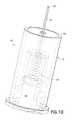
- FIG. 1is an elevational view of the safety pen assembly of the subject invention mounted onto an injector body
- FIG. 2is an exploded view of the safety pen assembly of the subject invention
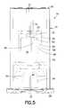
- FIGS. 3-7are various views of the safety pen assembly in an initial state with the proximal end of the needle being exposed;
- FIGS. 8-11are various views of the safety pen assembly in a shielded state with the proximal end of the needle being covered;
- FIGS. 12-13depict passive adjustment of the tabs
- FIGS. 14-18are various views of the shield
- FIGS. 19-22are various views of the hub
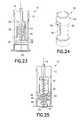
- FIGS. 23-25depict an alternative locking arrangement
- FIGS. 26-29depict a second embodiment of the safety pen needle assembly of the subject invention utilizing pivoting locking fingers.
- FIGS. 30-37depict a variation of the second embodiment of the subject invention.
- a safety pen needle assembly 10which generally includes a hub 12 , a needle 14 , a spring 16 , and a shield 18 . As described below, the assembly 10 is configured to shield the non-patient, or proximal end, of the needle 14 .
- the needle 14includes a distal end 20 , formed for insertion into a patient, and a proximal end 22 .
- the proximal end 22is formed for insertion into a drug vial or cartridge.
- the assembly 10is activatable to have the shield 18 cover the proximal end 22 .
- the assembly 10can be modified, or used in conjunction with other device(s), to provide shielding or coverage for the distal end 20 .
- the hub 12is formed with a tubular body 24 having a distal end 26 and a proximal end 28 .
- a channel 30is defined interiorly of the body 24 which extends between the distal and proximal ends 26 , 28 .
- a wall 32is disposed within the body 24 to extend transversely at least partially across the channel 30 .
- the needle 14extends through the channel 30 and is fixed to the hub 12 using any known technique.
- the needle 14is fixed to the hub 12 at the wall 32 .
- a collar 31FIG. 3
- the needle 14be fixed to the hub 12 with the distal end 20 being located distally of the wall 32 and the proximal end 22 being located proximally of the wall 32 .
- At least one adjustable tab 34is provided on the body 24 of the hub 12 , although, it is preferred that two diametrically opposed tabs 34 be provided.
- the tabs 34may be formed unitarily with the body 24 , or may be formed separately therefrom and be mounted to the body 24 .
- the tabs 34are formed to be adjustable from a first state, as shown in FIGS. 3-7 , to a second state, as shown in FIGS. 8-11 . In the first state, the tabs 34 extend inwardly from the body 24 so as to extend into the channel 30 . In being adjusted from the first state to the second state, the tabs 34 are adjusted radially outwardly so as to extend less into the channel 30 , as compared to the first state.
- the tabs 34are cantilevered to the body 24 and have an initial position in the first state.
- Windows 36may be formed in the body 24 about the tabs 34 to accommodate movement of the tabs 34 and to avoid interference between the tabs 34 and the body 24 upon movement of the tabs 34 from the first to the second states.
- the shield 18is disposed proximally of the wall 32 and at least partially within the hub 12 .
- the shield 18has a tubular body 38 with a distal end 40 and a proximal end 42 .
- a spring 16is disposed to urge the shield 18 proximally from a first, initial position to a second, final position.
- the spring 16is disposed between the shield 18 and the wall 32 .
- the shield 18in an initial state of the assembly 10 , the shield 18 is in the first position with the proximal end 22 of the needle 14 being exposed and ready for use.
- the tabs 34are in their first state, where the tabs 34 extend into the channel 30 .
- the tabs 34interferingly engage with the shield 18 to restrict proximal movement thereof.
- the tabs 34extend sufficiently radially inwardly into the channel 30 so as to overlap the proximal end 42 of the shield 18 , thus providing obstruction to proximal movement of the shield 18 .
- the tabs 34 and the shield 18are configured such that the tabs 34 in the first state retain the shield 18 in its first position with the proximal end 22 of the needle 14 being exposed.
- the tabs 34do not interferingly engage with the shield 18 and thus permit the shield 18 to be urged proximally to the second position under force of the spring 16 .
- the shield 18covers the proximal end 22 of the needle 14 . It is preferred that in the second position, the proximal end 42 of the shield 18 be located further proximally than the proximal end 22 of the needle 14 . With the proximal end 22 of the needle 14 being covered, inadvertent “needle sticks” by the proximal end 22 can be minimized or altogether avoided.
- features 44 for mounting the assembly 10 onto an injector body Psuch as a pen injector body
- an injector body Psuch as a pen injector body
- the features 44be defined inside the channel 30 and about the tabs 34 .
- the features 44may be threads or other features for cooperating engagement with an injector body.
- the features 44may also include a specific shape configuration (such as a taper to engage a Luer tip) for shape-mating engagement with an injector body.
- interengagement between the received portion of the injector body and the tabs 34may cause adjustment of the tabs 34 from the first state to the second state, as described above.
- the received portion of the injector body Pmay force the tabs 34 radially outwardly to the second state upon being sufficiently inserted into the body 24 .
- the interengagement of the injector body and the tabs 34causes the tabs 34 to adjust radially outwardly.
- the tabs 34are preferably shaped and positioned to be adjusted to the second state with the assembly 10 being mounted on an injector body for a normal dosage administration.
- the tabs 34do not prevent the shield 18 from moving to the second position.
- the injector bodyWith the injector body being received within the body 24 , the injector body 24 provides restraint against the shield 18 from moving to the second position.
- the spring 16urges the shield 18 to the second position.
- the tabs 34may be manually adjusted after use from the first to the second state. In contrast to the passive configuration described above, this would require an extra step or operation beyond a normal injection procedure.
- the tabs 34may be provided with handles (not shown) which extend through the windows 36 to be accessible from outside the assembly 10 . Post injection, the handles may be displaced outwardly, thus, causing the tabs 34 to be adjusted to the second state.
- the assembly 10be provided with a locking arrangement to lock the shield 18 in the second position.
- a locking arrangementmay be utilized.
- the shield 18may be formed with first and second locking arms 46 , 48 which are preferably angularly offset about the circumference of the shield 18 .
- the first and second locking arms 46 , 48are cantilevered and terminate with locking detents 50 .
- the locking detents 50may be protrusions extending from the respective locking arm(s) and/or may be defined by bent portions of the respective locking arm(s).
- the first locking arms 46are formed with greater length than the second locking arms 48 .
- a locking member 52is disposed within the body 24 . As best shown in FIG.
- the first and second locking arms 46 , 48 and the locking member 52are arranged such that in the second position of the shield 18 , the locking detents 50 of the first locking arms 46 are located on a distal side of the locking member 52 and the locking detents 50 of the second locking arms 48 are located on a proximal side of the locking member 52 .
- the second locking arms 48deflect inwardly to have the respective locking detents 50 by-pass the locking member 52 .
- the second locking arms 48be formed with sufficient resilience to snap back towards its undeflected states after the locking detents 50 by-pass the locking member 52 . This resilience also acts to retain the locking detents 50 in the locked position.
- the locking member 52may have a central aperture 54 formed to allow the shield 18 to translate therethrough.
- the first and second locking arms 46 , 48may engage the locking member 52 about the perimeter of the central aperture 54 .
- a guidewall 56may extend between the wall 32 and the locking member 52 .
- One or more slots 58may be formed in the guidewall 56 , and the first and/or second locking arms 46 , 48 may be formed to extend radially outwardly into the slots 58 . The positioning of the first and second locking arms 46 , 48 within the slots 58 limits rotational movement of the shield 18 .
- the guidewall 56is preferably formed to have a dimension slightly greater than the shield 18 to provide longitudinal stability thereto.
- the second locking arms 48need not be provided on the shield 18 .
- the shield 18may be formed with a shoulder 60 formed and positioned to be engaged by the tabs 34 after the injector body P is removed in limiting proximal movement of the shield 18 .
- the tabs 34after use, may be utilized to engage the locking detents 50 in limiting proximal movement of the shield 18 . This is particularly after the injector body P is removed, thus, allowing the tabs 34 to return to the first state extending into the channel 30 .
- the shoulder 60may act to retain the shield 18 even with circumferential misalignment between the tabs 34 and the locking detents 50 .
- the tabs 34prevent distal movement of the shield 18 .
- the first locking arms 46With the first locking arms 46 being used alone, the first locking arms 46 are provided with sufficient resilience to deflect inwardly and allow the locking detents 50 to by-pass the central aperture 54 . Upon sufficient proximal movement of the shield 18 , the locking detents 50 move clear of the central aperture 54 with the first locking arms 46 deflecting outwardly under force of inherent resilience. With the locking detents 50 being positioned as such ( FIG. 25 ), the locking detents 50 define a larger diameter than the central aperture 54 . In this manner, distal movement of the shield 18 may be prevented.
- the safety pen needle assembly 100generally includes a hub 102 , configured for mounting onto the pen injector P; a needle 104 having a distal end 106 , formed for insertion into a patient, and a proximal end 108 ; a shield 110 ; and, a spring 112 disposed to urge the shield 110 proximally towards the proximal end 108 of the needle 104 .
- the needle 104is fixed to the hub 102 .
- the hub 102includes at least one pivoting locking finger 114 .
- the natural state of the locking fingers 114is shown in FIG. 26 .
- FIG. 26shows the safety pen needle assembly 100 in an initial, pre-use state with the shield 110 being spaced from the proximal end 108 of the needle 104 , the proximal end 108 being exposed.
- the shield 110is formed with lower and upper grooves 116 - 118 , respectively.
- the lower and upper grooves 116 , 118are formed to receive a portion of the pivoting locking fingers 114 therein.
- the pivoting locking fingers 114are nested in the lower groove 116 .
- the interengagement of the pivoting locking fingers 114 and the lower groove 116maintains the shield 110 in the initial state against the biasing force of the spring 112 .
- the pivoting locking fingers 114are located slightly interiorly of the hub 102 so as to be engaged by the pen injector P when sufficiently received within the hub 102 .
- the pivoting locking fingers 114have inwardly facing tapered surfaces 113 extending into the interior of the hub 102 shaped and positioned to be engaged by the injector body P. With the tapered surfaces 113 , engagement with the pen injector P causes outward displacement of the pivoting locking fingers 114 with the pivoting locking fingers 114 coming out of engagement with the lower groove 116 .
- the outwardly displaced position of the pivoting locking fingers 114is shown in dashed lines.
- the shield 110is free to move proximally under force of the spring 112 .
- the injector body Prestricts such proximal movement.
- the spring 112urges the shield 110 proximally.
- the pivoting locking fingers 114return to their natural state, as shown in FIG. 29 .
- the pivoting locking fingers 114nest in the upper groove 118 of the shield 110 .
- the shield 110covers the proximal end 108 of the needle 104 .
- the interengagement of the pivoting locking fingers 114 with the upper groove 118prevents proximal or distal movement of the shield 110 , thus locking the shield 110 in the shielding state.
- locking grooves 120can be formed on the pivoting locking fingers 114 formed to nestingly receive either a lower or upper locking rim 122 , 124 formed on the shield 110 .
- the shield 110is held in an initial, pre-use state with the lower locking rim 122 being nestingly received in the locking grooves 120 of the pivoting locking fingers 114 .
- the tapered surfaces 113 of the pivoting locking fingers 114are located interiorly of the hub 102 so as to be engaged by the pen injector P when sufficiently received within the hub 102 . As shown in FIGS. 32 and 33 , engagement with the pen injector P causes outward displacement of the pivoting locking fingers 114 with the locking grooves 120 coming out of engagement with the lower locking rim 122 . The pen injector P may urge the shield 110 distally into the hub 102 , against the force of the spring 112 .
- the pen injector Pis withdrawn with the spring 112 urging the shield 110 proximally.
- the pivoting locking fingers 114return to the initial state.
- the locking grooves 120engage the upper locking rim 124 .
- the shield 110covers the proximal end 108 of the needle 104 .
- both proximal and distal movement of the shield 110is limited.
Landscapes
- Health & Medical Sciences (AREA)
- Engineering & Computer Science (AREA)
- Heart & Thoracic Surgery (AREA)
- Vascular Medicine (AREA)
- Anesthesiology (AREA)
- Biomedical Technology (AREA)
- Environmental & Geological Engineering (AREA)
- Hematology (AREA)
- Life Sciences & Earth Sciences (AREA)
- Animal Behavior & Ethology (AREA)
- General Health & Medical Sciences (AREA)
- Public Health (AREA)
- Veterinary Medicine (AREA)
- Infusion, Injection, And Reservoir Apparatuses (AREA)
Abstract
Description
Claims (9)
Priority Applications (1)
| Application Number | Priority Date | Filing Date | Title |
|---|---|---|---|
| US12/922,760US8801673B2 (en) | 2008-03-13 | 2009-03-13 | Safety pen needle assembly having shield for non-patient end |
Applications Claiming Priority (4)
| Application Number | Priority Date | Filing Date | Title |
|---|---|---|---|
| US3613808P | 2008-03-13 | 2008-03-13 | |
| US8475008P | 2008-07-30 | 2008-07-30 | |
| PCT/US2009/037039WO2009154826A2 (en) | 2008-03-13 | 2009-03-13 | Safety pen needle assembly having shield for non-patient end |
| US12/922,760US8801673B2 (en) | 2008-03-13 | 2009-03-13 | Safety pen needle assembly having shield for non-patient end |
Publications (2)
| Publication Number | Publication Date |
|---|---|
| US20120143145A1 US20120143145A1 (en) | 2012-06-07 |
| US8801673B2true US8801673B2 (en) | 2014-08-12 |
Family
ID=41434612
Family Applications (1)
| Application Number | Title | Priority Date | Filing Date |
|---|---|---|---|
| US12/922,760Active2031-12-11US8801673B2 (en) | 2008-03-13 | 2009-03-13 | Safety pen needle assembly having shield for non-patient end |
Country Status (5)
| Country | Link |
|---|---|
| US (1) | US8801673B2 (en) |
| EP (2) | EP3527246B1 (en) |
| CA (1) | CA2719209C (en) |
| ES (1) | ES2733497T3 (en) |
| WO (1) | WO2009154826A2 (en) |
Cited By (17)
| Publication number | Priority date | Publication date | Assignee | Title |
|---|---|---|---|---|
| US20140135706A1 (en)* | 2008-06-02 | 2014-05-15 | Sta-Med, Llc | Needle cover |
| USD847981S1 (en)* | 2016-08-10 | 2019-05-07 | Owen Mumford Limited | Safety pen needle |
| WO2020013886A1 (en)* | 2018-07-10 | 2020-01-16 | Becton, Dickinson And Company | Syringe assembly |
| US10682470B2 (en) | 2010-06-23 | 2020-06-16 | Sta-Med, Llc | Automatic-locking safety needle covers and methods of use and manufacture |
| US10737030B2 (en) | 2012-11-09 | 2020-08-11 | Iinjec Technologies Inc. | Fluid delivery device and method |
| USD914208S1 (en) | 2019-06-14 | 2021-03-23 | Owen Mumford Limited | Syringe component |
| US11116432B2 (en) | 2011-05-31 | 2021-09-14 | Sta-Med, Llc | Blood collection safety devices and methods of use and manufacture |
| USD938022S1 (en)* | 2016-08-10 | 2021-12-07 | Owen Mumford Limited | Safety pen needle |
| USD952136S1 (en) | 2019-06-14 | 2022-05-17 | Owen Mumford Limited | Syringe |
| USD959651S1 (en) | 2020-04-08 | 2022-08-02 | Owen Mumford Limited | Medical instrument |
| US20220331527A1 (en)* | 2019-09-06 | 2022-10-20 | Embecta Corp. | Pen needle with retractable shield |
| USD972745S1 (en) | 2020-05-07 | 2022-12-13 | Owen Mumford Limited | Testing device |
| USD1069617S1 (en) | 2021-03-29 | 2025-04-08 | Owen Mumford Limited | Testing device |
| USD1071161S1 (en) | 2022-10-17 | 2025-04-15 | Owen Mumford Limited | Medical injector |
| USD1071168S1 (en) | 2022-10-17 | 2025-04-15 | Owen Mumford Limited | Medical injector |
| USD1077210S1 (en) | 2022-11-18 | 2025-05-27 | Owen Mumford Limited | Medical injector |
| USD1078052S1 (en) | 2021-11-03 | 2025-06-03 | Owen Mumford Limited | Medical device |
Families Citing this family (4)
| Publication number | Priority date | Publication date | Assignee | Title |
|---|---|---|---|---|
| EP3527246B1 (en) | 2008-03-13 | 2022-02-16 | Becton, Dickinson and Company | Safety pen needle assembly having shield for non-patient end |
| WO2012146670A1 (en)* | 2011-04-28 | 2012-11-01 | Sanofi-Aventis Deutschland Gmbh | Dispense interface with lockout element |
| JP5844605B2 (en)* | 2011-10-31 | 2016-01-20 | 株式会社スズケン | Syringe |
| CN103405832B (en)* | 2012-10-30 | 2015-03-25 | 温州市贝普科技有限公司 | Safety insulin syringe |
Citations (103)
| Publication number | Priority date | Publication date | Assignee | Title |
|---|---|---|---|---|
| DE8909799U1 (en) | 1989-08-16 | 1989-09-28 | Nothdurft, Klaus, 7000 Stuttgart | Needle cover for cannulas |
| US4894055A (en) | 1988-12-28 | 1990-01-16 | Sudnak Paul J | Needle guard assembly for use with hypodermic syringes and the like |
| US4897083A (en) | 1988-05-09 | 1990-01-30 | Martell Michael D | Syringe needle guard |
| WO1990002515A1 (en) | 1988-09-16 | 1990-03-22 | Noergaard Tina Moeller | Liquid withdrawal equipment |
| US4998924A (en) | 1989-07-25 | 1991-03-12 | Sherwood Medical Company | Double sleeve safety syringe |
| US5061246A (en) | 1988-12-01 | 1991-10-29 | Effner Gmbh | Tube-like covering for protecting a surgical instrument, and method of making |
| WO1992009319A1 (en) | 1990-11-26 | 1992-06-11 | Dentoptic | Syringe with a needle protector device |
| WO1992020281A1 (en) | 1991-05-15 | 1992-11-26 | Stig Eric Weibel | Blood taking device |
| US5193552A (en) | 1989-03-14 | 1993-03-16 | Eastman Kodak Company | Needle device for safely collecting blood or injecting drugs |
| US5246428A (en) | 1992-07-30 | 1993-09-21 | Falknor Donald W | Needle safety mechanism |
| US5250037A (en) | 1992-12-18 | 1993-10-05 | Becton, Dickinson And Company | Syringe having needle isolation features |
| US5256153A (en) | 1989-03-02 | 1993-10-26 | Hake Lawrence W | Hypodermic needle guard and method to prevent needle stick injuries |
| US5269765A (en) | 1992-03-10 | 1993-12-14 | Injectimed, Inc. | Methods of manufacture of safety sleeves for medical injection devices |
| US5279579A (en) | 1990-04-18 | 1994-01-18 | Amico Elio D | Self-recapping injection needle assembly |
| US5292314A (en) | 1993-02-11 | 1994-03-08 | International Medical Consultants, Inc. | Automatic needle protector |
| US5336197A (en) | 1992-03-10 | 1994-08-09 | Injectimed, Inc. | Hard cover for protected injection apparatus |
| US5364362A (en) | 1992-02-19 | 1994-11-15 | Henke-Sass, Wolf Gmbh | Front syringe attachment for hypodermic syringes for subcutaneous injection in veterinary medicine |
| US5389085A (en) | 1993-02-11 | 1995-02-14 | International Medical Consultants, Inc. | Automatic needle protector |
| US5417662A (en) | 1991-09-13 | 1995-05-23 | Pharmacia Ab | Injection needle arrangement |
| US5514097A (en) | 1994-02-14 | 1996-05-07 | Genentech, Inc. | Self administered injection pen apparatus and method |
| US5562624A (en) | 1994-05-06 | 1996-10-08 | Righi; Nardino | Non-reusable safety syringe |
| US5591138A (en) | 1995-08-10 | 1997-01-07 | Vaillancourt; Vincent L. | Protected needle assembly |
| US5609577A (en) | 1996-01-29 | 1997-03-11 | Haber; Terry M. | Automatically locking hypodermic needle hiding shield for a dose metering syringe |
| US5634906A (en) | 1995-12-27 | 1997-06-03 | Habley Medical Technology Corporation | Needle hiding shield for a dose metering syringe |
| US5688241A (en) | 1996-04-15 | 1997-11-18 | Asbaghi; Hooman Ali | Automatic non-reusable needle guard |
| US5795336A (en) | 1993-02-11 | 1998-08-18 | Beech Medical Products, Inc. | Automatic needle protector having features for facilitating assembly |
| US5810775A (en) | 1997-05-23 | 1998-09-22 | Shaw; Thomas J. | Cap operated retractable medical device |
| US5873856A (en) | 1995-06-22 | 1999-02-23 | Pharmacia Ab | Limited depth penetration needle housing |
| US5964739A (en)* | 1998-06-18 | 1999-10-12 | Champ; Raynido A. | Safety disposable needle structure |
| US5971966A (en) | 1994-07-19 | 1999-10-26 | Novo Nordisk A/S | Needle magazine |
| USRE36398E (en) | 1985-07-29 | 1999-11-16 | Btg International Limited | Safety device for hypodermic needle or the like |
| US5984899A (en) | 1993-02-11 | 1999-11-16 | Beech Medical Products, Inc. | Needle protector device having a lockable protective cover which is unlockable during actuation |
| USRE36447E (en) | 1985-07-29 | 1999-12-14 | Btg International Limited | Safety device for hypodermic needle or the like |
| US6017329A (en) | 1989-03-02 | 2000-01-25 | Hake; Lawrence W. | Hypodermic needle guard and method to prevent needle stick injuries |
| US6110147A (en) | 1995-07-12 | 2000-08-29 | Societe D'etudes D'applications Techniques-Sedat | Self-protected injection syringe |
| US6203529B1 (en) | 1997-11-19 | 2001-03-20 | B D Medico | Needle arrangement |
| US6224576B1 (en) | 1999-11-04 | 2001-05-01 | Specialized Health Products, Inc. | Safety device for a needle having two sharpened ends |
| WO2001091837A1 (en) | 2000-05-31 | 2001-12-06 | Novo Nordisk A/S | A disposable double pointed injection needle, and an insulin injection system comprising a disposable double pointed injection needle |
| WO2001093924A1 (en) | 2000-06-05 | 2001-12-13 | Mdc Investment Holdings, Inc. | Fluid collection device having tilting retractable needle |
| US6379336B1 (en) | 1999-06-18 | 2002-04-30 | Hooman A. Asbaghi | Protective device for injection or aspiration needle |
| US20020193746A1 (en) | 1999-12-07 | 2002-12-19 | Stephane Chevallier | Safety system for a syringe |
| US20030014018A1 (en) | 2000-08-02 | 2003-01-16 | Lucio Giambattista | Pen needle and safety shield system |
| US6547764B2 (en) | 2000-05-31 | 2003-04-15 | Novo Nordisk A/S | Double pointed injection needle |
| WO2003045480A1 (en) | 2001-11-30 | 2003-06-05 | Novo Nordisk A/S | A safety needle assembly |
| WO2003105935A2 (en) | 2002-06-13 | 2003-12-24 | Star Syringe Limited | Needlestick prevention device |
| WO2004000397A1 (en) | 2002-06-22 | 2003-12-31 | Barry Peter Liversidge | Medical needle assemblies |
| US6692463B1 (en) | 1999-11-02 | 2004-02-17 | Owen Mumford Limited | Syringe holder |
| WO2004030539A1 (en) | 2002-10-02 | 2004-04-15 | Greiner Bio-One Gmbh | Receiving device comprising an adjustable covering element |
| US20040122379A1 (en) | 2001-03-20 | 2004-06-24 | Rainer Bosse | Cannula protecting cover |
| US20040133172A1 (en) | 2002-06-07 | 2004-07-08 | Becton, Dickinson And Company | Needle safety device |
| US6773415B2 (en) | 2000-03-01 | 2004-08-10 | Disetronic Services Ag | Disposable injector cap |
| WO2004071560A1 (en) | 2003-02-11 | 2004-08-26 | Weston Terence E | A safety needle |
| US6796967B2 (en) | 2001-10-22 | 2004-09-28 | Nps Pharmaceuticals, Inc. | Injection needle assembly |
| EP1464353A1 (en) | 2000-01-27 | 2004-10-06 | Afra Design PTY. Limited | A single-use syringe |
| US20050113750A1 (en) | 2003-11-21 | 2005-05-26 | Targell David J. | Safety needle |
| US6939330B1 (en) | 2002-12-12 | 2005-09-06 | Medsolve Llc | Syringe insertion system |
| WO2005097238A2 (en) | 2004-03-30 | 2005-10-20 | Pediamed Pharmaceuticals, Inc. | Automatic injection device |
| WO2006018626A1 (en) | 2004-08-18 | 2006-02-23 | Barry Peter Liversidge | Injection apparatus |
| US20060095010A1 (en) | 2004-10-29 | 2006-05-04 | Safety Syringes, Inc. | Syringe with anti-rotation for luer lock |
| US7066907B2 (en) | 1997-07-16 | 2006-06-27 | Owen Mumford Limited | Injection devices |
| US7074211B1 (en) | 1999-06-07 | 2006-07-11 | Tecpharma Licensing Ag | Apparatus for subcutaneous administration of an injectable product |
| WO2006072807A1 (en) | 2005-01-08 | 2006-07-13 | Barry Peter Liversidge | Medical needle safety devices |
| FR2881053A1 (en) | 2005-01-25 | 2006-07-28 | Sedat Sa | Syringe needle protecting device comprises a tubular body, an injection piston assembled in a sliding motion, protective support, a mobile needle cover and a deployment element |
| US20060270984A1 (en) | 2003-11-05 | 2006-11-30 | Edgar Hommann | Automatic injection device |
| US7147624B2 (en) | 2000-09-08 | 2006-12-12 | Tecpharma Licensing Ag | Needle protecting device |
| EP1747789A2 (en) | 2002-07-03 | 2007-01-31 | Novo Nordisk A/S | A needle mounting system and a method for mounting a needle assembly |
| US20070027430A1 (en) | 2003-12-18 | 2007-02-01 | Edgar Hommann | Trigger-activatable injection device |
| US7198617B2 (en) | 2004-11-05 | 2007-04-03 | Visual Connection, Inc. | Passively guarded, fillable injection syringe |
| US20070129674A1 (en) | 2003-10-09 | 2007-06-07 | Liversidge Barry P | Latching blocking mechanisms and safety medical needle assemblies |
| US7229432B2 (en) | 2001-08-10 | 2007-06-12 | Owen Mumford Limited | Injection devices |
| WO2007077463A1 (en) | 2006-01-06 | 2007-07-12 | Tip-Top.Com Ltd. | Medical needle safety device |
| US20070173772A1 (en) | 2004-02-14 | 2007-07-26 | Liversidge Barry P | Medical injector handling device |
| US7278986B1 (en) | 2005-03-09 | 2007-10-09 | Frost Robert J | Safety syringe with needle |
| US20070255225A1 (en) | 1999-10-14 | 2007-11-01 | Alchas Paul G | Intradermal Needle |
| US20080009807A1 (en) | 2003-09-11 | 2008-01-10 | Edgar Hommann | Administration device with an insertion mechanism and a delivery mechanism |
| DE102006022081B3 (en) | 2006-05-11 | 2008-01-31 | Tecpharma Licensing Ag | Injection section length adjusting device for injection needle, has stop mechanism connected with needle guard in axially firm or fixed manner and is in stop contact during movement of guard in proximal direction with another mechanism |
| WO2008025179A1 (en) | 2006-09-01 | 2008-03-06 | Tecpharma Licensing Ag | Safety pin module comprising a locking mechanism and a user identification |
| WO2008028312A1 (en) | 2006-09-06 | 2008-03-13 | Tecpharma Licensing Ag | Needle protection device with a blocked protection position |
| WO2008028304A1 (en) | 2006-09-06 | 2008-03-13 | Tecpharma Licensing Ag | Needle protection device with a blocked protective position |
| WO2008028305A1 (en) | 2006-09-06 | 2008-03-13 | Tecpharma Licensing Ag | Needle protection device comprising a distal protection element and a proximal protection element |
| US20080071225A1 (en) | 2002-11-25 | 2008-03-20 | Tecpharma Licensing Ag | Injection apparatus comprising a needle-protecting device |
| US20080077093A1 (en) | 2006-09-06 | 2008-03-27 | Christian Gratwohl | Needle protecting device comprising a lock |
| DE102006041810A1 (en) | 2006-09-06 | 2008-03-27 | Tecpharma Licensing Ag | Needle unit for medicine injection device, has guide part with locking units that are arranged axially behind one another, and blocking device overriding locking units in distal direction during movement of needle protective cover |
| WO2008035122A1 (en) | 2006-09-22 | 2008-03-27 | Barry Peter Liversidge | Medical needle safety device |
| WO2008043188A1 (en) | 2006-10-10 | 2008-04-17 | Tecpharma Licensing Ag | Injection device comprising a trigger lock when no product receptacle has been inserted |
| WO2008044067A1 (en) | 2006-10-11 | 2008-04-17 | Barry Peter Liversidge | Safety needle pack |
| US20080103454A1 (en) | 2006-09-06 | 2008-05-01 | Christian Gratwohl | Needle protecting device comprising a releaseably blocked needle protector |
| WO2008050158A2 (en) | 2006-10-27 | 2008-05-02 | Barry Peter Liversidge | Medical needle safety devices |
| US7370759B2 (en) | 2002-11-25 | 2008-05-13 | Tecpharma Licensing Ag | Device for temporarily retaining a protective needle cap of an injection apparatus |
| US7374558B2 (en) | 2002-01-30 | 2008-05-20 | Techpharma Licensing Ag | Injection device comprising a sterilely attached injection needle and a needle support and ampoule for such an injection device |
| US7384414B1 (en) | 2007-01-23 | 2008-06-10 | Becton, Dickinson And Company | Safety pen needle with non-injection end passive safety features |
| WO2008083037A1 (en) | 2006-12-26 | 2008-07-10 | Stat Medical Devices, Inc. | Pen needle tip |
| US20080249477A1 (en) | 2007-04-05 | 2008-10-09 | West Pharmaceutical Services, Inc. | Pen injector having a needle shield |
| US20080262436A1 (en) | 2004-11-24 | 2008-10-23 | Shl Medical Ab | Injection Device |
| US7442185B2 (en) | 2000-12-14 | 2008-10-28 | Shl Group Ab | Auto-injector |
| US20080269691A1 (en) | 2005-09-01 | 2008-10-30 | Brook Hill | Needle Shroud Assembly |
| WO2009003300A1 (en) | 2007-06-29 | 2009-01-08 | Tecpharma Licensing Ag | Injection device with a spring for a needle guard sleeve |
| WO2009030056A1 (en) | 2007-09-04 | 2009-03-12 | Tecpharma Licensing Ag | Protective cap for a needle |
| WO2009114762A1 (en) | 2008-03-13 | 2009-09-17 | Becton, Dickinson And Company | Safety pen needle assembly having shielding for patient and non-patient ends |
| US7635350B2 (en) | 2002-11-25 | 2009-12-22 | Tecpharma Licensing Ag | Auto-injector comprising a resettable releasing safety device |
| WO2009154826A9 (en) | 2008-03-13 | 2010-02-25 | Becton, Dickinson And Company | Safety pen needle assembly having shield for non-patient end |
| US20100114035A1 (en) | 2007-03-07 | 2010-05-06 | Novo Nordisk A/S | Back needle |
| WO2010126432A1 (en) | 2009-04-27 | 2010-11-04 | Shl Group Ab | Safety pen needle device |
- 2009
- 2009-03-13EPEP19165745.1Apatent/EP3527246B1/enactiveActive
- 2009-03-13CACA2719209Apatent/CA2719209C/enactiveActive
- 2009-03-13EPEP09767139.0Apatent/EP2262559B1/enactiveActive
- 2009-03-13WOPCT/US2009/037039patent/WO2009154826A2/enactiveApplication Filing
- 2009-03-13ESES09767139Tpatent/ES2733497T3/enactiveActive
- 2009-03-13USUS12/922,760patent/US8801673B2/enactiveActive
Patent Citations (121)
| Publication number | Priority date | Publication date | Assignee | Title |
|---|---|---|---|---|
| USRE36398E (en) | 1985-07-29 | 1999-11-16 | Btg International Limited | Safety device for hypodermic needle or the like |
| USRE36447E (en) | 1985-07-29 | 1999-12-14 | Btg International Limited | Safety device for hypodermic needle or the like |
| US4897083A (en) | 1988-05-09 | 1990-01-30 | Martell Michael D | Syringe needle guard |
| WO1990002515A1 (en) | 1988-09-16 | 1990-03-22 | Noergaard Tina Moeller | Liquid withdrawal equipment |
| US5061246A (en) | 1988-12-01 | 1991-10-29 | Effner Gmbh | Tube-like covering for protecting a surgical instrument, and method of making |
| US4894055A (en) | 1988-12-28 | 1990-01-16 | Sudnak Paul J | Needle guard assembly for use with hypodermic syringes and the like |
| US6017329A (en) | 1989-03-02 | 2000-01-25 | Hake; Lawrence W. | Hypodermic needle guard and method to prevent needle stick injuries |
| US5256153A (en) | 1989-03-02 | 1993-10-26 | Hake Lawrence W | Hypodermic needle guard and method to prevent needle stick injuries |
| US5193552A (en) | 1989-03-14 | 1993-03-16 | Eastman Kodak Company | Needle device for safely collecting blood or injecting drugs |
| US4998924A (en) | 1989-07-25 | 1991-03-12 | Sherwood Medical Company | Double sleeve safety syringe |
| DE8909799U1 (en) | 1989-08-16 | 1989-09-28 | Nothdurft, Klaus, 7000 Stuttgart | Needle cover for cannulas |
| US5279579A (en) | 1990-04-18 | 1994-01-18 | Amico Elio D | Self-recapping injection needle assembly |
| WO1992009319A1 (en) | 1990-11-26 | 1992-06-11 | Dentoptic | Syringe with a needle protector device |
| US5429612A (en) | 1990-11-26 | 1995-07-04 | Dentoptic | Syringe with a slidable needle protection device |
| WO1992020281A1 (en) | 1991-05-15 | 1992-11-26 | Stig Eric Weibel | Blood taking device |
| US5417662A (en) | 1991-09-13 | 1995-05-23 | Pharmacia Ab | Injection needle arrangement |
| US5364362A (en) | 1992-02-19 | 1994-11-15 | Henke-Sass, Wolf Gmbh | Front syringe attachment for hypodermic syringes for subcutaneous injection in veterinary medicine |
| US5269765A (en) | 1992-03-10 | 1993-12-14 | Injectimed, Inc. | Methods of manufacture of safety sleeves for medical injection devices |
| US5336197A (en) | 1992-03-10 | 1994-08-09 | Injectimed, Inc. | Hard cover for protected injection apparatus |
| US5246428A (en) | 1992-07-30 | 1993-09-21 | Falknor Donald W | Needle safety mechanism |
| US5250037A (en) | 1992-12-18 | 1993-10-05 | Becton, Dickinson And Company | Syringe having needle isolation features |
| US5292314A (en) | 1993-02-11 | 1994-03-08 | International Medical Consultants, Inc. | Automatic needle protector |
| US5984899A (en) | 1993-02-11 | 1999-11-16 | Beech Medical Products, Inc. | Needle protector device having a lockable protective cover which is unlockable during actuation |
| US5389085A (en) | 1993-02-11 | 1995-02-14 | International Medical Consultants, Inc. | Automatic needle protector |
| US5795336A (en) | 1993-02-11 | 1998-08-18 | Beech Medical Products, Inc. | Automatic needle protector having features for facilitating assembly |
| US5514097A (en) | 1994-02-14 | 1996-05-07 | Genentech, Inc. | Self administered injection pen apparatus and method |
| US5562624A (en) | 1994-05-06 | 1996-10-08 | Righi; Nardino | Non-reusable safety syringe |
| US5971966A (en) | 1994-07-19 | 1999-10-26 | Novo Nordisk A/S | Needle magazine |
| US5873856A (en) | 1995-06-22 | 1999-02-23 | Pharmacia Ab | Limited depth penetration needle housing |
| US6110147A (en) | 1995-07-12 | 2000-08-29 | Societe D'etudes D'applications Techniques-Sedat | Self-protected injection syringe |
| US6569124B1 (en) | 1995-07-12 | 2003-05-27 | Societe D'etudes Et D'applications Techniques-Sedat | Self-protected injection syringe |
| US5591138A (en) | 1995-08-10 | 1997-01-07 | Vaillancourt; Vincent L. | Protected needle assembly |
| US5634906A (en) | 1995-12-27 | 1997-06-03 | Habley Medical Technology Corporation | Needle hiding shield for a dose metering syringe |
| US5609577A (en) | 1996-01-29 | 1997-03-11 | Haber; Terry M. | Automatically locking hypodermic needle hiding shield for a dose metering syringe |
| US5688241A (en) | 1996-04-15 | 1997-11-18 | Asbaghi; Hooman Ali | Automatic non-reusable needle guard |
| US5810775A (en) | 1997-05-23 | 1998-09-22 | Shaw; Thomas J. | Cap operated retractable medical device |
| US7066907B2 (en) | 1997-07-16 | 2006-06-27 | Owen Mumford Limited | Injection devices |
| US6203529B1 (en) | 1997-11-19 | 2001-03-20 | B D Medico | Needle arrangement |
| US5964739A (en)* | 1998-06-18 | 1999-10-12 | Champ; Raynido A. | Safety disposable needle structure |
| US7074211B1 (en) | 1999-06-07 | 2006-07-11 | Tecpharma Licensing Ag | Apparatus for subcutaneous administration of an injectable product |
| US6379336B1 (en) | 1999-06-18 | 2002-04-30 | Hooman A. Asbaghi | Protective device for injection or aspiration needle |
| US20070255225A1 (en) | 1999-10-14 | 2007-11-01 | Alchas Paul G | Intradermal Needle |
| US6692463B1 (en) | 1999-11-02 | 2004-02-17 | Owen Mumford Limited | Syringe holder |
| US6224576B1 (en) | 1999-11-04 | 2001-05-01 | Specialized Health Products, Inc. | Safety device for a needle having two sharpened ends |
| US20020193746A1 (en) | 1999-12-07 | 2002-12-19 | Stephane Chevallier | Safety system for a syringe |
| EP1464353A1 (en) | 2000-01-27 | 2004-10-06 | Afra Design PTY. Limited | A single-use syringe |
| US6773415B2 (en) | 2000-03-01 | 2004-08-10 | Disetronic Services Ag | Disposable injector cap |
| WO2001091837A1 (en) | 2000-05-31 | 2001-12-06 | Novo Nordisk A/S | A disposable double pointed injection needle, and an insulin injection system comprising a disposable double pointed injection needle |
| US6547764B2 (en) | 2000-05-31 | 2003-04-15 | Novo Nordisk A/S | Double pointed injection needle |
| WO2001093924A1 (en) | 2000-06-05 | 2001-12-13 | Mdc Investment Holdings, Inc. | Fluid collection device having tilting retractable needle |
| US6986760B2 (en) | 2000-08-02 | 2006-01-17 | Becton, Dickinson And Company | Pen needle and safety shield system |
| US20030014018A1 (en) | 2000-08-02 | 2003-01-16 | Lucio Giambattista | Pen needle and safety shield system |
| US7147624B2 (en) | 2000-09-08 | 2006-12-12 | Tecpharma Licensing Ag | Needle protecting device |
| US7442185B2 (en) | 2000-12-14 | 2008-10-28 | Shl Group Ab | Auto-injector |
| US20040122379A1 (en) | 2001-03-20 | 2004-06-24 | Rainer Bosse | Cannula protecting cover |
| US7361166B2 (en) | 2001-03-20 | 2008-04-22 | Tecpharma Licensing Ag | Cannula protecting cover |
| US20080255526A1 (en) | 2001-03-20 | 2008-10-16 | Tecpharma Licensing Ag. | Cannula protecting cover |
| US7229432B2 (en) | 2001-08-10 | 2007-06-12 | Owen Mumford Limited | Injection devices |
| US6796967B2 (en) | 2001-10-22 | 2004-09-28 | Nps Pharmaceuticals, Inc. | Injection needle assembly |
| US6855129B2 (en) | 2001-11-30 | 2005-02-15 | Novo Nordisk A/S | Safety needle assembly |
| US20030120209A1 (en) | 2001-11-30 | 2003-06-26 | Karsten Jensen | Safety needle assembly |
| WO2003045480A1 (en) | 2001-11-30 | 2003-06-05 | Novo Nordisk A/S | A safety needle assembly |
| US7374558B2 (en) | 2002-01-30 | 2008-05-20 | Techpharma Licensing Ag | Injection device comprising a sterilely attached injection needle and a needle support and ampoule for such an injection device |
| US20040133172A1 (en) | 2002-06-07 | 2004-07-08 | Becton, Dickinson And Company | Needle safety device |
| US20050267410A1 (en) | 2002-06-13 | 2005-12-01 | Marc Koska | Needlestick prevention device |
| WO2003105935A2 (en) | 2002-06-13 | 2003-12-24 | Star Syringe Limited | Needlestick prevention device |
| US20050277893A1 (en) | 2002-06-22 | 2005-12-15 | Liversidge Barry P | Medical needle assemblies |
| WO2004000397A1 (en) | 2002-06-22 | 2003-12-31 | Barry Peter Liversidge | Medical needle assemblies |
| EP1747789A2 (en) | 2002-07-03 | 2007-01-31 | Novo Nordisk A/S | A needle mounting system and a method for mounting a needle assembly |
| US20050288607A1 (en) | 2002-10-02 | 2005-12-29 | Franz Konrad | Receiving device comprising an adjustable covering element |
| WO2004030539A1 (en) | 2002-10-02 | 2004-04-15 | Greiner Bio-One Gmbh | Receiving device comprising an adjustable covering element |
| US7370759B2 (en) | 2002-11-25 | 2008-05-13 | Tecpharma Licensing Ag | Device for temporarily retaining a protective needle cap of an injection apparatus |
| US7635350B2 (en) | 2002-11-25 | 2009-12-22 | Tecpharma Licensing Ag | Auto-injector comprising a resettable releasing safety device |
| US7361160B2 (en) | 2002-11-25 | 2008-04-22 | Tecpharma Licensing Ag | Injection apparatus comprising a needle-protecting device |
| US20080071225A1 (en) | 2002-11-25 | 2008-03-20 | Tecpharma Licensing Ag | Injection apparatus comprising a needle-protecting device |
| US6939330B1 (en) | 2002-12-12 | 2005-09-06 | Medsolve Llc | Syringe insertion system |
| WO2004071560A1 (en) | 2003-02-11 | 2004-08-26 | Weston Terence E | A safety needle |
| US20080009807A1 (en) | 2003-09-11 | 2008-01-10 | Edgar Hommann | Administration device with an insertion mechanism and a delivery mechanism |
| US20070129674A1 (en) | 2003-10-09 | 2007-06-07 | Liversidge Barry P | Latching blocking mechanisms and safety medical needle assemblies |
| US20060270984A1 (en) | 2003-11-05 | 2006-11-30 | Edgar Hommann | Automatic injection device |
| US20050113750A1 (en) | 2003-11-21 | 2005-05-26 | Targell David J. | Safety needle |
| US20070027430A1 (en) | 2003-12-18 | 2007-02-01 | Edgar Hommann | Trigger-activatable injection device |
| US20070173772A1 (en) | 2004-02-14 | 2007-07-26 | Liversidge Barry P | Medical injector handling device |
| WO2005097238A2 (en) | 2004-03-30 | 2005-10-20 | Pediamed Pharmaceuticals, Inc. | Automatic injection device |
| US20070156101A1 (en) | 2004-08-18 | 2007-07-05 | Liversidge Barry P | Injection Apparatus |
| WO2006018626A1 (en) | 2004-08-18 | 2006-02-23 | Barry Peter Liversidge | Injection apparatus |
| US20060095010A1 (en) | 2004-10-29 | 2006-05-04 | Safety Syringes, Inc. | Syringe with anti-rotation for luer lock |
| US7198617B2 (en) | 2004-11-05 | 2007-04-03 | Visual Connection, Inc. | Passively guarded, fillable injection syringe |
| US20080262436A1 (en) | 2004-11-24 | 2008-10-23 | Shl Medical Ab | Injection Device |
| US20080103453A1 (en) | 2005-01-08 | 2008-05-01 | Barry Peter Liversidge | Medical Needle Safety Devices |
| WO2006072807A1 (en) | 2005-01-08 | 2006-07-13 | Barry Peter Liversidge | Medical needle safety devices |
| FR2881053A1 (en) | 2005-01-25 | 2006-07-28 | Sedat Sa | Syringe needle protecting device comprises a tubular body, an injection piston assembled in a sliding motion, protective support, a mobile needle cover and a deployment element |
| US7278986B1 (en) | 2005-03-09 | 2007-10-09 | Frost Robert J | Safety syringe with needle |
| US20080269691A1 (en) | 2005-09-01 | 2008-10-30 | Brook Hill | Needle Shroud Assembly |
| US20090005742A1 (en) | 2006-01-06 | 2009-01-01 | Barry Peter Liversidge | Medical Needle Safety Device |
| WO2007077463A1 (en) | 2006-01-06 | 2007-07-12 | Tip-Top.Com Ltd. | Medical needle safety device |
| DE102006022081B3 (en) | 2006-05-11 | 2008-01-31 | Tecpharma Licensing Ag | Injection section length adjusting device for injection needle, has stop mechanism connected with needle guard in axially firm or fixed manner and is in stop contact during movement of guard in proximal direction with another mechanism |
| WO2008025179A1 (en) | 2006-09-01 | 2008-03-06 | Tecpharma Licensing Ag | Safety pin module comprising a locking mechanism and a user identification |
| US8177745B2 (en) | 2006-09-01 | 2012-05-15 | Tecpharma Licensing Ag | Needle safety module comprising a locking mechanism and a user identification |
| US20090259178A1 (en) | 2006-09-01 | 2009-10-15 | Jonas Brechbuehler | Needle safety module comprising a locking mechanism and a user identification |
| WO2008028312A1 (en) | 2006-09-06 | 2008-03-13 | Tecpharma Licensing Ag | Needle protection device with a blocked protection position |
| US20080103454A1 (en) | 2006-09-06 | 2008-05-01 | Christian Gratwohl | Needle protecting device comprising a releaseably blocked needle protector |
| US20080077093A1 (en) | 2006-09-06 | 2008-03-27 | Christian Gratwohl | Needle protecting device comprising a lock |
| US20090259196A1 (en) | 2006-09-06 | 2009-10-15 | Christian Gratwohl | Needle protection device with a blocked protection position |
| US20090221972A1 (en) | 2006-09-06 | 2009-09-03 | Christian Gratwohl | Needle protection device with a blocked protective position |
| WO2008028305A1 (en) | 2006-09-06 | 2008-03-13 | Tecpharma Licensing Ag | Needle protection device comprising a distal protection element and a proximal protection element |
| WO2008028304A1 (en) | 2006-09-06 | 2008-03-13 | Tecpharma Licensing Ag | Needle protection device with a blocked protective position |
| DE102006041810A1 (en) | 2006-09-06 | 2008-03-27 | Tecpharma Licensing Ag | Needle unit for medicine injection device, has guide part with locking units that are arranged axially behind one another, and blocking device overriding locking units in distal direction during movement of needle protective cover |
| WO2008035122A1 (en) | 2006-09-22 | 2008-03-27 | Barry Peter Liversidge | Medical needle safety device |
| WO2008043188A1 (en) | 2006-10-10 | 2008-04-17 | Tecpharma Licensing Ag | Injection device comprising a trigger lock when no product receptacle has been inserted |
| WO2008044067A1 (en) | 2006-10-11 | 2008-04-17 | Barry Peter Liversidge | Safety needle pack |
| WO2008050158A2 (en) | 2006-10-27 | 2008-05-02 | Barry Peter Liversidge | Medical needle safety devices |
| WO2008083037A1 (en) | 2006-12-26 | 2008-07-10 | Stat Medical Devices, Inc. | Pen needle tip |
| US7384414B1 (en) | 2007-01-23 | 2008-06-10 | Becton, Dickinson And Company | Safety pen needle with non-injection end passive safety features |
| US20100114035A1 (en) | 2007-03-07 | 2010-05-06 | Novo Nordisk A/S | Back needle |
| US20080249477A1 (en) | 2007-04-05 | 2008-10-09 | West Pharmaceutical Services, Inc. | Pen injector having a needle shield |
| WO2009003300A1 (en) | 2007-06-29 | 2009-01-08 | Tecpharma Licensing Ag | Injection device with a spring for a needle guard sleeve |
| WO2009030056A1 (en) | 2007-09-04 | 2009-03-12 | Tecpharma Licensing Ag | Protective cap for a needle |
| WO2009154826A9 (en) | 2008-03-13 | 2010-02-25 | Becton, Dickinson And Company | Safety pen needle assembly having shield for non-patient end |
| WO2009114762A1 (en) | 2008-03-13 | 2009-09-17 | Becton, Dickinson And Company | Safety pen needle assembly having shielding for patient and non-patient ends |
| WO2010126432A1 (en) | 2009-04-27 | 2010-11-04 | Shl Group Ab | Safety pen needle device |
Non-Patent Citations (2)
| Title |
|---|
| Clickfine ® AutoProtect(TM); YPSOMED Selfcare Solutions; www.ypsomed.com/b2b@ypsomed.com. |
| Clickfine ® AutoProtect™; YPSOMED Selfcare Solutions; www.ypsomed.com/b2b@ypsomed.com. |
Cited By (25)
| Publication number | Priority date | Publication date | Assignee | Title |
|---|---|---|---|---|
| US11090443B2 (en) | 2008-06-02 | 2021-08-17 | Sta-Med, Llc | Needle cover |
| US11992665B2 (en) | 2008-06-02 | 2024-05-28 | Sta-Med, Llc | Needle cover |
| US10335554B2 (en)* | 2008-06-02 | 2019-07-02 | Sta-Med, Llc | Needle cover |
| US20140135706A1 (en)* | 2008-06-02 | 2014-05-15 | Sta-Med, Llc | Needle cover |
| US10682470B2 (en) | 2010-06-23 | 2020-06-16 | Sta-Med, Llc | Automatic-locking safety needle covers and methods of use and manufacture |
| US11992666B2 (en) | 2010-06-23 | 2024-05-28 | Sta-Med, Llc | Automatic-locking safety needle covers and methods of use and manufacture |
| US12274550B2 (en) | 2011-05-31 | 2025-04-15 | Sta-Med, Llc | Blood collection safety devices and methods of use and manufacture |
| US11116432B2 (en) | 2011-05-31 | 2021-09-14 | Sta-Med, Llc | Blood collection safety devices and methods of use and manufacture |
| US10737030B2 (en) | 2012-11-09 | 2020-08-11 | Iinjec Technologies Inc. | Fluid delivery device and method |
| USD959654S1 (en)* | 2016-08-10 | 2022-08-02 | Owen Mumford Limited | Safety pen needle |
| USD938022S1 (en)* | 2016-08-10 | 2021-12-07 | Owen Mumford Limited | Safety pen needle |
| USD847981S1 (en)* | 2016-08-10 | 2019-05-07 | Owen Mumford Limited | Safety pen needle |
| WO2020013886A1 (en)* | 2018-07-10 | 2020-01-16 | Becton, Dickinson And Company | Syringe assembly |
| US12383467B2 (en) | 2018-07-10 | 2025-08-12 | Becton, Dickinson And Company | Syringe assembly |
| USD952136S1 (en) | 2019-06-14 | 2022-05-17 | Owen Mumford Limited | Syringe |
| USD914208S1 (en) | 2019-06-14 | 2021-03-23 | Owen Mumford Limited | Syringe component |
| US20220331527A1 (en)* | 2019-09-06 | 2022-10-20 | Embecta Corp. | Pen needle with retractable shield |
| US12296156B2 (en)* | 2019-09-06 | 2025-05-13 | Embecta Corp. | Pen needle with retractable shield |
| USD959651S1 (en) | 2020-04-08 | 2022-08-02 | Owen Mumford Limited | Medical instrument |
| USD972745S1 (en) | 2020-05-07 | 2022-12-13 | Owen Mumford Limited | Testing device |
| USD1069617S1 (en) | 2021-03-29 | 2025-04-08 | Owen Mumford Limited | Testing device |
| USD1078052S1 (en) | 2021-11-03 | 2025-06-03 | Owen Mumford Limited | Medical device |
| USD1071161S1 (en) | 2022-10-17 | 2025-04-15 | Owen Mumford Limited | Medical injector |
| USD1071168S1 (en) | 2022-10-17 | 2025-04-15 | Owen Mumford Limited | Medical injector |
| USD1077210S1 (en) | 2022-11-18 | 2025-05-27 | Owen Mumford Limited | Medical injector |
Also Published As
| Publication number | Publication date |
|---|---|
| WO2009154826A3 (en) | 2010-04-15 |
| WO2009154826A2 (en) | 2009-12-23 |
| EP2262559B1 (en) | 2019-05-01 |
| ES2733497T3 (en) | 2019-11-29 |
| EP3527246A2 (en) | 2019-08-21 |
| CA2719209A1 (en) | 2009-12-23 |
| EP3527246A3 (en) | 2019-09-04 |
| EP3527246B1 (en) | 2022-02-16 |
| WO2009154826A9 (en) | 2010-02-25 |
| EP2262559A2 (en) | 2010-12-22 |
| CA2719209C (en) | 2016-10-18 |
| US20120143145A1 (en) | 2012-06-07 |
Similar Documents
| Publication | Publication Date | Title |
|---|---|---|
| US8801673B2 (en) | Safety pen needle assembly having shield for non-patient end | |
| US8632503B2 (en) | Safety pen needle assembly having shielding for patient and non-patient ends | |
| US8876781B2 (en) | Safety pen needle device | |
| US9694141B2 (en) | Needle safety device | |
| US9078977B2 (en) | Dual shielded syringe | |
| US9498579B2 (en) | Safety needle assembly | |
| US20020133122A1 (en) | Pen needle and safety shield system | |
| US20140243760A1 (en) | Needle safety device | |
| US20140236095A1 (en) | Needle Safety Device | |
| WO2023091965A1 (en) | Retractable shield for pen needle assembly | |
| US9320857B2 (en) | Needle safety device | |
| ES2912468T3 (en) | Pen Needle Safety Assembly with Non-Patient End Guard | |
| WO2023172269A1 (en) | Safety pen needle assembly | |
| HK1195273B (en) | Needle safety device |
Legal Events
| Date | Code | Title | Description |
|---|---|---|---|
| AS | Assignment | Owner name:BECTON, DICKINSON AND COMPANY, NEW JERSEY Free format text:ASSIGNMENT OF ASSIGNORS INTEREST;ASSIGNORS:ZAIKEN, ELIOT;RICHARDS, STEPHEN;QUINN, MICHAEL VINCENT;SIGNING DATES FROM 20111017 TO 20111027;REEL/FRAME:027360/0323 | |
| AS | Assignment | Owner name:BECTON, DICKINSON AND COMPANY, NEW JERSEY Free format text:ASSIGNMENT OF ASSIGNORS INTEREST;ASSIGNOR:ALU, JOSEPH;REEL/FRAME:027598/0011 Effective date:20120113 | |
| STCF | Information on status: patent grant | Free format text:PATENTED CASE | |
| MAFP | Maintenance fee payment | Free format text:PAYMENT OF MAINTENANCE FEE, 4TH YEAR, LARGE ENTITY (ORIGINAL EVENT CODE: M1551) Year of fee payment:4 | |
| MAFP | Maintenance fee payment | Free format text:PAYMENT OF MAINTENANCE FEE, 8TH YEAR, LARGE ENTITY (ORIGINAL EVENT CODE: M1552); ENTITY STATUS OF PATENT OWNER: LARGE ENTITY Year of fee payment:8 | |
| AS | Assignment | Owner name:EMBECTA CORP., MASSACHUSETTS Free format text:ASSIGNMENT OF ASSIGNORS INTEREST;ASSIGNOR:BECTON, DICKINSON AND COMPANY;REEL/FRAME:059721/0617 Effective date:20220331 | |
| AS | Assignment | Owner name:MORGAN STANLEY SENIOR FUNDING, INC., AS COLLATERAL AGENT, MARYLAND Free format text:FIRST LIEN TERM PATENT SECURITY AGREEMENT;ASSIGNOR:EMBECTA CORP.;REEL/FRAME:063028/0318 Effective date:20230309 | |
| AS | Assignment | Owner name:U.S. BANK TRUST COMPANY, NATIONAL ASSOCIATION, AS NOTES COLLATERAL AGENT, NEW JERSEY Free format text:FIRST LIEN PATENT SECURITY AGREEMENT (SENIOR SECURED NOTES);ASSIGNOR:EMBECTA CORP.;REEL/FRAME:063780/0053 Effective date:20230309 | |
| AS | Assignment | Owner name:U.S. BANK TRUST COMPANY, NATIONAL ASSOCIATION, AS NOTES COLLATERAL AGENT, NEW JERSEY Free format text:FIRST LIEN PATENT SECURITY AGREEMENT (SENIOR SECURED NOTES);ASSIGNOR:EMBECTA CORP.;REEL/FRAME:063083/0071 Effective date:20230309 |