US8800527B2 - Method and apparatus for providing adaptive swirl injection and ignition - Google Patents
Method and apparatus for providing adaptive swirl injection and ignitionDownload PDFInfo
- Publication number
- US8800527B2 US8800527B2US13/797,753US201313797753AUS8800527B2US 8800527 B2US8800527 B2US 8800527B2US 201313797753 AUS201313797753 AUS 201313797753AUS 8800527 B2US8800527 B2US 8800527B2
- Authority
- US
- United States
- Prior art keywords
- fuel
- plasma
- electrode portion
- valve
- combustion chamber
- Prior art date
- Legal status (The legal status is an assumption and is not a legal conclusion. Google has not performed a legal analysis and makes no representation as to the accuracy of the status listed.)
- Expired - Fee Related
Links
- 238000000034methodMethods0.000titleclaimsdescription27
- 238000002347injectionMethods0.000titleabstractdescription44
- 239000007924injectionSubstances0.000titleabstractdescription44
- 230000003044adaptive effectEffects0.000titleabstractdescription31
- 239000000446fuelSubstances0.000claimsabstractdescription192
- 230000004913activationEffects0.000claimsabstractdescription24
- 238000007493shaping processMethods0.000claimsabstractdescription18
- 230000004044responseEffects0.000claimsabstractdescription17
- 238000002485combustion reactionMethods0.000claimsdescription108
- 239000007800oxidant agentSubstances0.000claimsdescription71
- 230000001590oxidative effectEffects0.000claimsdescription63
- 239000012530fluidSubstances0.000claimsdescription16
- 238000004891communicationMethods0.000claimsdescription7
- 239000000696magnetic materialSubstances0.000claimsdescription7
- 150000002500ionsChemical class0.000description41
- 238000005516engineering processMethods0.000description35
- 239000002245particleSubstances0.000description33
- 238000001994activationMethods0.000description21
- 238000012546transferMethods0.000description21
- 230000001133accelerationEffects0.000description16
- 230000033001locomotionEffects0.000description15
- 238000007906compressionMethods0.000description14
- VNWKTOKETHGBQD-UHFFFAOYSA-NmethaneChemical compoundCVNWKTOKETHGBQD-UHFFFAOYSA-N0.000description14
- 230000006835compressionEffects0.000description13
- 239000007789gasSubstances0.000description11
- RTZKZFJDLAIYFH-UHFFFAOYSA-NDiethyl etherChemical compoundCCOCCRTZKZFJDLAIYFH-UHFFFAOYSA-N0.000description9
- 238000004519manufacturing processMethods0.000description9
- 238000005457optimizationMethods0.000description8
- 230000035515penetrationEffects0.000description8
- 239000013598vectorSubstances0.000description8
- 230000003647oxidationEffects0.000description7
- 238000007254oxidation reactionMethods0.000description7
- QGZKDVFQNNGYKY-UHFFFAOYSA-NAmmoniaChemical compoundNQGZKDVFQNNGYKY-UHFFFAOYSA-N0.000description6
- LCGLNKUTAGEVQW-UHFFFAOYSA-NDimethyl etherChemical compoundCOCLCGLNKUTAGEVQW-UHFFFAOYSA-N0.000description6
- ATUOYWHBWRKTHZ-UHFFFAOYSA-NPropaneChemical compoundCCCATUOYWHBWRKTHZ-UHFFFAOYSA-N0.000description6
- 239000002283diesel fuelSubstances0.000description6
- 230000006870functionEffects0.000description6
- 238000010438heat treatmentMethods0.000description6
- 230000001965increasing effectEffects0.000description6
- 238000003860storageMethods0.000description6
- 238000004804windingMethods0.000description6
- 150000001298alcoholsChemical class0.000description5
- 239000000835fiberSubstances0.000description5
- 239000001257hydrogenSubstances0.000description5
- 229910052739hydrogenInorganic materials0.000description5
- 125000004435hydrogen atomChemical class[H]*0.000description5
- 239000000463materialSubstances0.000description5
- OKTJSMMVPCPJKN-UHFFFAOYSA-NCarbonChemical compound[C]OKTJSMMVPCPJKN-UHFFFAOYSA-N0.000description4
- 230000009286beneficial effectEffects0.000description4
- 230000008901benefitEffects0.000description4
- 238000006243chemical reactionMethods0.000description4
- 239000003795chemical substances by applicationSubstances0.000description4
- 238000001816coolingMethods0.000description4
- 238000011161developmentMethods0.000description4
- 239000000203mixtureSubstances0.000description4
- 230000008569processEffects0.000description4
- 239000000126substanceSubstances0.000description4
- UGFAIRIUMAVXCW-UHFFFAOYSA-NCarbon monoxideChemical compound[O+]#[C-]UGFAIRIUMAVXCW-UHFFFAOYSA-N0.000description3
- OTMSDBZUPAUEDD-UHFFFAOYSA-NEthaneChemical compoundCCOTMSDBZUPAUEDD-UHFFFAOYSA-N0.000description3
- OKKJLVBELUTLKV-UHFFFAOYSA-NMethanolChemical compoundOCOKKJLVBELUTLKV-UHFFFAOYSA-N0.000description3
- CBENFWSGALASAD-UHFFFAOYSA-NOzoneChemical compound[O-][O+]=OCBENFWSGALASAD-UHFFFAOYSA-N0.000description3
- 229910021529ammoniaInorganic materials0.000description3
- 239000001273butaneSubstances0.000description3
- 229910052799carbonInorganic materials0.000description3
- 229910002091carbon monoxideInorganic materials0.000description3
- 239000000567combustion gasSubstances0.000description3
- 239000004020conductorSubstances0.000description3
- 125000004122cyclic groupChemical group0.000description3
- 238000006073displacement reactionMethods0.000description3
- 238000009826distributionMethods0.000description3
- 230000005684electric fieldEffects0.000description3
- 230000020169heat generationEffects0.000description3
- 238000009413insulationMethods0.000description3
- 239000010687lubricating oilSubstances0.000description3
- 238000012544monitoring processMethods0.000description3
- IJDNQMDRQITEOD-UHFFFAOYSA-Nn-butaneChemical compoundCCCCIJDNQMDRQITEOD-UHFFFAOYSA-N0.000description3
- OFBQJSOFQDEBGM-UHFFFAOYSA-Nn-pentaneNatural productsCCCCCOFBQJSOFQDEBGM-UHFFFAOYSA-N0.000description3
- 239000001294propaneSubstances0.000description3
- 230000002889sympathetic effectEffects0.000description3
- CURLTUGMZLYLDI-UHFFFAOYSA-NCarbon dioxideChemical compoundO=C=OCURLTUGMZLYLDI-UHFFFAOYSA-N0.000description2
- LFQSCWFLJHTTHZ-UHFFFAOYSA-NEthanolChemical compoundCCOLFQSCWFLJHTTHZ-UHFFFAOYSA-N0.000description2
- CPLXHLVBOLITMK-UHFFFAOYSA-NMagnesium oxideChemical compound[Mg]=OCPLXHLVBOLITMK-UHFFFAOYSA-N0.000description2
- 230000009471actionEffects0.000description2
- XAGFODPZIPBFFR-UHFFFAOYSA-NaluminiumChemical compound[Al]XAGFODPZIPBFFR-UHFFFAOYSA-N0.000description2
- 229910052782aluminiumInorganic materials0.000description2
- 239000003990capacitorSubstances0.000description2
- 150000001716carbazolesChemical class0.000description2
- 239000000470constituentSubstances0.000description2
- 239000002826coolantSubstances0.000description2
- 230000001351cycling effectEffects0.000description2
- 238000000151depositionMethods0.000description2
- 230000008021depositionEffects0.000description2
- 230000029087digestionEffects0.000description2
- 238000010494dissociation reactionMethods0.000description2
- 230000005593dissociationsEffects0.000description2
- 230000008030eliminationEffects0.000description2
- 238000003379elimination reactionMethods0.000description2
- 230000001976improved effectEffects0.000description2
- 230000000977initiatory effectEffects0.000description2
- -1jetSubstances0.000description2
- 239000003921oilSubstances0.000description2
- 230000003287optical effectEffects0.000description2
- 230000037361pathwayEffects0.000description2
- 230000001681protective effectEffects0.000description2
- 238000005086pumpingMethods0.000description2
- 238000000197pyrolysisMethods0.000description2
- 230000001172regenerating effectEffects0.000description2
- HBMJWWWQQXIZIP-UHFFFAOYSA-Nsilicon carbideChemical compound[Si+]#[C-]HBMJWWWQQXIZIP-UHFFFAOYSA-N0.000description2
- 229910010271silicon carbideInorganic materials0.000description2
- 239000004071sootSubstances0.000description2
- 229910000601superalloyInorganic materials0.000description2
- 238000007725thermal activationMethods0.000description2
- XLYOFNOQVPJJNP-UHFFFAOYSA-NwaterSubstancesOXLYOFNOQVPJJNP-UHFFFAOYSA-N0.000description2
- 229910000851Alloy steelInorganic materials0.000description1
- CIWBSHSKHKDKBQ-JLAZNSOCSA-NAscorbic acidChemical compoundOC[C@H](O)[C@H]1OC(=O)C(O)=C1OCIWBSHSKHKDKBQ-JLAZNSOCSA-N0.000description1
- 229910000531Co alloyInorganic materials0.000description1
- 229910000990Ni alloyInorganic materials0.000description1
- 239000000654additiveSubstances0.000description1
- 230000002528anti-freezeEffects0.000description1
- 238000003491arrayMethods0.000description1
- 230000000712assemblyEffects0.000description1
- 238000000429assemblyMethods0.000description1
- QVGXLLKOCUKJST-UHFFFAOYSA-Natomic oxygenChemical compound[O]QVGXLLKOCUKJST-UHFFFAOYSA-N0.000description1
- 230000005540biological transmissionEffects0.000description1
- 229910002092carbon dioxideInorganic materials0.000description1
- 239000001569carbon dioxideSubstances0.000description1
- 230000015556catabolic processEffects0.000description1
- 230000001413cellular effectEffects0.000description1
- 239000000919ceramicSubstances0.000description1
- 238000004140cleaningMethods0.000description1
- 239000010941cobaltSubstances0.000description1
- GUTLYIVDDKVIGB-UHFFFAOYSA-Ncobalt atomChemical compound[Co]GUTLYIVDDKVIGB-UHFFFAOYSA-N0.000description1
- 230000000295complement effectEffects0.000description1
- 239000002131composite materialSubstances0.000description1
- 150000001875compoundsChemical class0.000description1
- PMHQVHHXPFUNSP-UHFFFAOYSA-Mcopper(1+);methylsulfanylmethane;bromideChemical compoundBr[Cu].CSCPMHQVHHXPFUNSP-UHFFFAOYSA-M0.000description1
- 230000008878couplingEffects0.000description1
- 238000010168coupling processMethods0.000description1
- 238000005859coupling reactionMethods0.000description1
- 238000006731degradation reactionMethods0.000description1
- 238000001514detection methodMethods0.000description1
- 239000003989dielectric materialSubstances0.000description1
- 230000005611electricityEffects0.000description1
- 238000005868electrolysis reactionMethods0.000description1
- 230000002708enhancing effectEffects0.000description1
- 150000002170ethersChemical class0.000description1
- 239000003502gasolineSubstances0.000description1
- 229910002804graphiteInorganic materials0.000description1
- 239000010439graphiteSubstances0.000description1
- 229930195733hydrocarbonNatural products0.000description1
- 150000002430hydrocarbonsChemical class0.000description1
- 230000003116impacting effectEffects0.000description1
- 230000001939inductive effectEffects0.000description1
- 239000003999initiatorSubstances0.000description1
- 230000003993interactionEffects0.000description1
- 239000000395magnesium oxideSubstances0.000description1
- 238000012423maintenanceMethods0.000description1
- 230000007246mechanismEffects0.000description1
- 230000005055memory storageEffects0.000description1
- 238000012986modificationMethods0.000description1
- 230000004048modificationEffects0.000description1
- 239000003345natural gasSubstances0.000description1
- 239000010815organic wasteSubstances0.000description1
- 239000001301oxygenSubstances0.000description1
- 229910052760oxygenInorganic materials0.000description1
- 239000000843powderSubstances0.000description1
- 239000002244precipitateSubstances0.000description1
- 238000012545processingMethods0.000description1
- 239000010453quartzSubstances0.000description1
- 230000005855radiationEffects0.000description1
- 230000009467reductionEffects0.000description1
- 230000008439repair processEffects0.000description1
- 230000006903response to temperatureEffects0.000description1
- 229910052594sapphireInorganic materials0.000description1
- 239000010980sapphireSubstances0.000description1
- 238000000926separation methodMethods0.000description1
- VYPSYNLAJGMNEJ-UHFFFAOYSA-Nsilicon dioxideInorganic materialsO=[Si]=OVYPSYNLAJGMNEJ-UHFFFAOYSA-N0.000description1
- 239000011029spinelSubstances0.000description1
- 229910052596spinelInorganic materials0.000description1
- 239000010959steelSubstances0.000description1
- 239000013589supplementSubstances0.000description1
- 230000001960triggered effectEffects0.000description1
- 239000002966varnishSubstances0.000description1
Images


Classifications
- F—MECHANICAL ENGINEERING; LIGHTING; HEATING; WEAPONS; BLASTING
- F02—COMBUSTION ENGINES; HOT-GAS OR COMBUSTION-PRODUCT ENGINE PLANTS
- F02M—SUPPLYING COMBUSTION ENGINES IN GENERAL WITH COMBUSTIBLE MIXTURES OR CONSTITUENTS THEREOF
- F02M57/00—Fuel-injectors combined or associated with other devices
- F02M57/06—Fuel-injectors combined or associated with other devices the devices being sparking plugs
- F—MECHANICAL ENGINEERING; LIGHTING; HEATING; WEAPONS; BLASTING
- F02—COMBUSTION ENGINES; HOT-GAS OR COMBUSTION-PRODUCT ENGINE PLANTS
- F02M—SUPPLYING COMBUSTION ENGINES IN GENERAL WITH COMBUSTIBLE MIXTURES OR CONSTITUENTS THEREOF
- F02M51/00—Fuel-injection apparatus characterised by being operated electrically
- F02M51/06—Injectors peculiar thereto with means directly operating the valve needle
- F02M51/061—Injectors peculiar thereto with means directly operating the valve needle using electromagnetic operating means
- F02M51/0689—Injectors peculiar thereto with means directly operating the valve needle using electromagnetic operating means and permanent magnets
- F02M51/0692—Injectors peculiar thereto with means directly operating the valve needle using electromagnetic operating means and permanent magnets as valve or armature return means
- F—MECHANICAL ENGINEERING; LIGHTING; HEATING; WEAPONS; BLASTING
- F02—COMBUSTION ENGINES; HOT-GAS OR COMBUSTION-PRODUCT ENGINE PLANTS
- F02M—SUPPLYING COMBUSTION ENGINES IN GENERAL WITH COMBUSTIBLE MIXTURES OR CONSTITUENTS THEREOF
- F02M53/00—Fuel-injection apparatus characterised by having heating, cooling or thermally-insulating means
- F02M53/04—Injectors with heating, cooling, or thermally-insulating means
- F02M53/043—Injectors with heating, cooling, or thermally-insulating means with cooling means other than air cooling
- F—MECHANICAL ENGINEERING; LIGHTING; HEATING; WEAPONS; BLASTING
- F02—COMBUSTION ENGINES; HOT-GAS OR COMBUSTION-PRODUCT ENGINE PLANTS
- F02M—SUPPLYING COMBUSTION ENGINES IN GENERAL WITH COMBUSTIBLE MIXTURES OR CONSTITUENTS THEREOF
- F02M61/00—Fuel-injectors not provided for in groups F02M39/00 - F02M57/00 or F02M67/00
- F02M61/16—Details not provided for in, or of interest apart from, the apparatus of groups F02M61/02 - F02M61/14
- F02M61/162—Means to impart a whirling motion to fuel upstream or near discharging orifices
- F02M61/163—Means being injection-valves with helically or spirally shaped grooves
- F—MECHANICAL ENGINEERING; LIGHTING; HEATING; WEAPONS; BLASTING
- F02—COMBUSTION ENGINES; HOT-GAS OR COMBUSTION-PRODUCT ENGINE PLANTS
- F02P—IGNITION, OTHER THAN COMPRESSION IGNITION, FOR INTERNAL-COMBUSTION ENGINES; TESTING OF IGNITION TIMING IN COMPRESSION-IGNITION ENGINES
- F02P13/00—Sparking plugs structurally combined with other parts of internal-combustion engines
- F—MECHANICAL ENGINEERING; LIGHTING; HEATING; WEAPONS; BLASTING
- F02—COMBUSTION ENGINES; HOT-GAS OR COMBUSTION-PRODUCT ENGINE PLANTS
- F02P—IGNITION, OTHER THAN COMPRESSION IGNITION, FOR INTERNAL-COMBUSTION ENGINES; TESTING OF IGNITION TIMING IN COMPRESSION-IGNITION ENGINES
- F02P23/00—Other ignition
- F02P23/04—Other physical ignition means, e.g. using laser rays
- F—MECHANICAL ENGINEERING; LIGHTING; HEATING; WEAPONS; BLASTING
- F02—COMBUSTION ENGINES; HOT-GAS OR COMBUSTION-PRODUCT ENGINE PLANTS
- F02M—SUPPLYING COMBUSTION ENGINES IN GENERAL WITH COMBUSTIBLE MIXTURES OR CONSTITUENTS THEREOF
- F02M2200/00—Details of fuel-injection apparatus, not otherwise provided for
- F02M2200/95—Fuel injection apparatus operating on particular fuels, e.g. biodiesel, ethanol, mixed fuels
Definitions
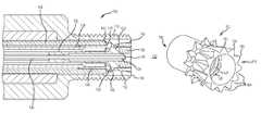
- FIG. 1is a cross-sectional side view in elevation of an injector-igniter according to a first representative embodiment
- FIG. 2is a partial cross-sectional side view of the injector-igniter shown in FIG. 1 ;
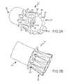
- FIG. 3Ais a perspective view of the valve seat electrode shown in FIGS. 1 and 2 ;
- FIG. 3Bis a perspective view of the valve seat electrode shown in FIGS. 1-3A ;
- FIG. 4Ais a side view in elevation of a valve seat electrode according to another representative embodiment
- FIG. 4Bis a perspective view of the valve seat electrode shown in FIG. 4A ;
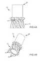
- FIG. 5is a perspective view illustrating a representative swirl pattern according to the present technology
- FIG. 6is a perspective view illustrating another representative swirl pattern according to the present technology.
- FIG. 7is a perspective view illustrating an additional representative swirl pattern according to the present technology.
- FIG. 8is a perspective view illustrating yet another representative swirl pattern according to the present technology.
- FIG. 9is a perspective view illustrating a further representative swirl pattern according to the present technology.
- FIG. 10is a partial cross-sectional perspective view of an injector-igniter according to a second representative embodiment
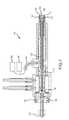
- FIG. 11is a cross-sectional side view in elevation of an injector-igniter according to a third representative embodiment
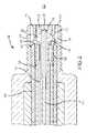
- FIG. 12is a cross-sectional side view in elevation of an injector-igniter according to a fourth representative embodiment
- FIG. 13is a cross-sectional side view in elevation of an injector-igniter according to a fifth representative embodiment.
- FIG. 14is a cross-sectional side view in elevation of an injector-igniter according to a sixth representative embodiment.
- injector-ignitersaccording to several representative embodiments that provide adaptive swirl injection and ignition.
- Adaptive swirl injection and ignitionenables utilization of less expensive fuels, such as hydrogen, methane, various alcohols, and other alternative fuels.
- Adaptive swirl injection and ignitionenables optimization of combustion and stratified heat generation to achieve greater air utilization efficiency than is typical in compression-ignition engines using diesel fuel. Accordingly, objectionable emissions may be greatly reduced or eliminated.
- a fuel injector-ignitercomprises a housing, an actuator, and a valve.
- the valveincludes a valve head operative to open and close against a valve seat in response to activation of the actuator.
- the valve seatincludes an electrode portion extending beyond the valve head and within the housing to form at least one gap, such as an annular gap.
- a current discharge between the housing and electrode portionestablishes plasma and electro-magnetic forces that drive the plasma from the gap.
- the injector-ignitermay further comprise one or more power supplies connected to the housing and valve seat that is operative to provide fuel valve operation and/or the current discharge.
- the electrode portionincludes a plurality of flow shaping features, such as a plurality of fins disposed around the electrode portion.
- the finsare twisted, and thereby operative to impart a rotation or swirl to the plasma.
- the electrode portionincludes a plurality of ports in fluid communication with the annular gap.
- the electrode portioncomprises a magnetic material.
- a fuel injector-ignitercomprises a housing, a power supply, an actuator, a valve, and a valve seat electrode.
- the valve seat electrodeincludes a valve seat and an electrode portion extending beyond the valve seat within the housing to form an annular gap.
- the valveincludes a valve head operative to open and close against the valve seat in response to activation of the actuator.
- the power supplyis operative to produce a current discharge between the housing and electrode portion establishing plasma and electro-magnetic forces that drive the plasma from the annular gap.
- the methodcomprises introducing the fuel into an annular region between two electrodes; providing a current across the two electrodes and through the fuel to establish a plasma; maintaining the current across the two electrodes to establish Lorentz forces driving the plasma from the annular region and into the combustion chamber; and imparting rotation on the fuel and plasma as it is driven from the annular region.
- the methodfurther comprises applying a rapid application of voltage to the two electrodes whereby ionization between the two electrodes is avoided, thereby causing a corona discharge to extend into the combustion chamber.
- the combustion chambercontains a rotating oxidant and the rotation of the fuel and plasma is counter to the rotating oxidant.
- the rotation of the fuel and plasmais the same direction as the rotating oxidant.
- the rotation of the fuel and plasmais imparted via a plurality of flow shaping features disposed on at least one of the two electrodes. In other embodiments the rotation is induced by a magnetic field.
- Some aspects of the technology described belowmay take the form of computer-executable instructions, including routines executed by a programmable computer. Those skilled in the relevant art will appreciate that the technology can be practiced on computer systems other than those shown and described below.
- the technologycan be embodied in a special-purpose computer or data processor, such as an engine control unit (ECU), engine control module (ECM), fuel system controller, or the like, that is specifically programmed, configured or constructed to perform one or more of the computer-executable instructions described below.
- ECUengine control unit
- ECMengine control module
- fuel system controlleror the like
- the term “computer,” “processor,” or “controller” as generally used hereinrefers to any data processor and can include ECUs, ECMs, and modules, as well as Internet appliances and hand-held devices (including palm-top computers, wearable computers, cellular or mobile phones, multi-processor systems, processor-based or programmable consumer electronics, network computers, mini computers and the like). Information handled by these computers can be presented at any suitable display medium, including a CRT display, LCD, or dedicated display device or mechanism (e.g., gauge).
- the technologycan also be practiced in distributed environments, where tasks or modules are performed by remote processing devices that are linked through a communications network.
- program modules or subroutinesmay be located in local and remote memory storage devices.
- aspects of the technology described belowmay be stored or distributed on computer-readable media, including magnetic or optically readable or removable computer disks, as well as distributed electronically over networks.
- Such networksmay include, for example and without limitation, Controller Area Networks (CAN), Local Interconnect Networks (LIN), and the like.
- CANController Area Networks
- LINLocal Interconnect Networks
- data structures and transmissions of data particular to aspects of the technologyare also encompassed within the scope of the technology.
- FIGS. 1 and 2show an injector-igniter 102 incorporating adaptive swirl injection and ignition technology according to a first representative embodiment.
- Injector-igniter 102is provided with a microprocessor or computer 101 to control injection of fuel supplied through a valve seat electrode 112 .
- the controller 101 and igniter circuits 104 , 106are shown as separate components or assemblies, in other embodiments the functions of the controller 101 and circuits 104 , 106 may be integrated into a compact control unit.
- Injector-igniter 102receives fuel from a suitable supply such as a pipeline or vehicle fuel system (not shown) providing fuel to the injector-igniter at variable pressure through pressure regulator 117 .
- Fuelflows through and/or around armature 118 , along annular passageway 120 and the stem connecting armature 118 to valve head 122 to a valve seat electrode 112 as shown in FIG. 2 .
- Valve seat electrode 112includes a valve seat 124 , an electrode portion 116 , and a ferrule 180 for attachment to conductor tube 128 .
- valve actuator 118opens the fuel metering valve by lifting valve head 122 off of valve seat 124 (see FIG.
- Radial ports 126are formed through the electrode portion 116 adjacent the seat 124 . Fuel flows through radial ports 126 and into the annular passageway between the electrode portion 114 of the housing 110 and electrode portion 116 of the valve seat electrode 112 as shown.
- power supply 104provides a relatively long duration electric field through cable 108 to conductive tube 128 and through electrode valve seat 112 (including electrode portion 116 ) to produce sufficient field strength for initial ionization of the fuel and/or air that is between electrodes 114 and edge or tips 115 of electrode 112 - 116 .
- the electrical resistancedrops and the current rapidly builds between electrodes 114 and 116 which causes Lorentz thrust towards the combustion chamber 132 .
- Adaptive control of the launch velocity into combustion chamber 132 of the population of ions that form the current, along with other particles that are swept along,is established by the current as provided by circuit 104 , which is adjustable from sub-sonic to super-sonic speeds.
- Such Lorentz launches of ionized particlesmay be repeated at an adaptively controlled frequency to produce waves of ionized bursts into the combustion chamber.
- Ignition events triggered by adaptively adjusted Lorentz thrusting of ion current through the oxidant and/or fuelproduces the desired penetration and combustion pattern.
- Instrumentationsuch as fiber optic linked sensors 134 provide feedback information to computer 101 about the penetration extend and pattern for purposes of such adaptive adjustment for optimization of achievements such as stratified heat release, engine performance, fuel economy and emissions reductions or elimination.
- controller 101may further provide another type of combustion initiation and/or acceleration, such as corona discharge, by operation of circuit 106 .
- Circuit 106is operative to provide one or more sufficiently rapid applications of voltage to avoid ionization between electrodes 114 and 116 thereby causing a corona discharge to extend into or occur near or within the stratified distribution of particles previously launched by a Lorentz thrusting event as described above.
- Such adaptive control of various parameters and combinations including fuel pressure, fuel flow periods, ionized particle Lorentz thrust accelerations, and corona ignitionprovides the ability to interchangeably optimize applications of a wide range of alternative fuels such as hydrogen, producer gas, landfill gas, methane, natural gas, ethane, propane, butane, fuel alcohols, and ammonia along with gasoline, jet, and diesel fuels including preheated fuels.
- alternative fuelssuch as hydrogen, producer gas, landfill gas, methane, natural gas, ethane, propane, butane, fuel alcohols, and ammonia along with gasoline, jet, and diesel fuels including preheated fuels.
- electrode portion 116may include flow shaping channels 184 located between fins 182 .
- the valve seat electrode 112may be made of permanent magnet materials or include electromagnets to provide magnetic focusing and/or radial acceleration of ions that are thrust into the combustion chamber. Shaping fins 182 and/or channels 184 launch ions and/or other swept particles that traverse pre-existing oxidant swirl in the combustion chamber 132 . In this embodiment the electrode portion 116 launches the ions straight (e.g., radially) into the combustion chamber.
- the valve seat electrode 112may be made from a sintered, powdered magnetic material, for example. In other embodiments, the valve seat electrode 112 may be made from a suitable steel, cobalt or nickel alloy for use as an electromagnet.
- FIGS. 4A and 4Billustrate a valve seat electrode 212 according to another representative embodiment.
- Valve seat electrode 212includes an interior valve seat, an electrode portion 216 , fuel ports 226 , and a ferrule 280 , all similar to valve seat electrode 112 described above. Except, in this case, the fins 282 may in selected regions and extents be volutes or otherwise twisted clockwise or counterclockwise depending upon whether it is desired to complement pre-existing swirl of oxidant in the combustion chamber or to oppose it.
- the angles of the fins and integrated patterns of oxidant and/or fuel particles and/or ion projections into the combustion chamberare thus adjustable according to fuel supply pressure, magnetic influences, and current developed across the electrodes.
- Electrode current controlscan be varied as the current is thrust to adjust the included angle and penetration distance of any number of patterns that are thrust at variable intervals into the oxidant in combustion chamber 132 for purposes of maximizing oxidant-utilization efficiency and engine performance.
- the helical electrode features 282 and corresponding channels 284produce or enhance the angular velocity of ion currents that are accelerated by the Lorentz thrust.
- the injection patternmay be influenced or controlled by magnetic forces exerted by one or more magnets (e.g., permanent or electro).
- magnetse.g., permanent or electro
- ring magnet 130 with selected north and south pole positions or patternsis disposed on valve head 122 , which positions ring magnet 130 near the annular region between electrodes 114 and 116 . Accordingly, ring magnet 130 is operative to influence the current that is accelerated from the annular region.
- Ring magnet 130may be a permanent magnet or an electromagnet.
- Embodiments using an electromagnetprovide for adaptive adjustment of the included angle for activated oxidant ion or fuel injection as a function of the variable fuel pressure supplied to the injector and Lorentz thrust velocity.
- Helical electrode features and pathwaysmay be mild or highly exaggerated to interact with or enhance such adaptive adjustments and/or to increase the heat transfers for thermal activation purposes.
- Swirl induced stratified pattern control as provided by the presently disclosed technologycan be optimized for each type of combustion chamber and swirl conditions that may be encountered in various engines including two- and four-stroke piston engines. This provides improved air utilization efficiency in which air supplies the oxidant particles required for accelerated completion of combustion along with effective thermal insulation of combustion gases, and expansive work production by such insulating air that receives heat and/or kinetic energy by such operations.
- FIG. 5illustrates an example of injector swirl that complements the air flow within cylinder 500 .
- Fuel and/or oxidant fluid ion and/or particle injection vectors 506extend from a centrally positioned injector 501 .
- Injector 501is equipped with a valve seat electrode having an electrode portion with a fin configuration similar to that shown in FIGS. 4A and 4B . Except, in this case the fins are twisted the opposite direction to provide swirl that is sympathetic to the oxidant flow in the chamber 504 .
- FIG. 6illustrates an example without injector swirl, wherein the injection vectors 606 are directed radially into the oxidant air flow 602 .
- the injectoris equipped with a valve seat electrode having an electrode portion with a fin configuration similar to that shown in FIGS. 3A and 3B .
- the finsextend axially with respect to the injector.
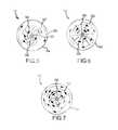
- FIG. 7illustrates an example of injector swirl that is counter to the air flow within cylinder 700 .
- Fuel and/or oxidant fluid ion and/or particle injection vectors 706initially are opposed to the oxidant air flow 702 as shown.
- the injectoris equipped with a valve seat electrode having an electrode portion with a fin configuration similar to that shown in FIGS. 4A and 4B .
- the finsare twisted to provide swirl that is counter to the oxidant flow in the combustion chamber 704 .
- This configurationis particularly beneficial for operation in relatively high compression ratio engines and/or at higher supercharger boost pressures. Such conditions of operation produce more concentrated availability of oxygen such that combustion can be completed in a smaller volume of oxidant to maximize air utilization efficiency.
- FIG. 8illustrates another example of injector swirl that is counter to the air flow within cylinder 800 .
- This embodimentoptimizes one or more oxidant ionizations and launches such ions in to a stratified oxidant charge that is overtaken by higher velocity launches of fuel ions.
- Fuel and/or oxidant fluid ion and/or particle injection vectors 806initially are opposed to the oxidant air flow 802 as shown.
- the injectoris equipped with a valve seat electrode having an electrode portion with a fin configuration similar to that shown in FIGS. 4A and 4B .
- the finsare twisted to provide swirl that is counter to the oxidant flow in the chamber 804 .
- Such operation of oxidant activationwhich may be accomplished just prior to fuel injection is particularly beneficial for operation in relatively lower compression ratio engines and/or at lower supercharger boost pressures. Accordingly more activated oxidant is available and combustion can be completed in a smaller volume of oxidant to maximize air utilization efficiency.
- FIG. 9illustrates another example of swirl optimization.
- the combustion chamber 904includes an air flow pattern 902 which tumbles within cylinder 900 .
- the cylinder air flowhas a generally clockwise swirl of oxidant 902 around an axis more or less perpendicular to the piston motion axis in a portion of combustion chamber 904 .
- Fuel and/or oxidant fluid ion and/or particle injection vectors 906 from a centrally positioned injector 901may be opposed, sympathetic or transverse to oxidant swirl 902 .
- suitable sensors 134such as piezoelectric, thermoelectric, photoelectric, and/or Fabry-Perot type sensors, monitor the pressure and temperature produced by combustion chamber events and transmit such information by wireless or optical communication channels, such as fiber optic bundle 136 , to computer 101 .
- some or all sensors 134may include protective lens 138 in order to protect such sensors from the harsh environment of the combustion chamber 132 as well as control the field of view of the sensor.
- Lens 138may be configured to provide a sufficiently wide-angle view of the combustion chamber and provide high-speed feedback to controller 101 to facilitate various operational adjustments in order to maximize net energy conversion efficiency and to protect the combustion chamber and power train components.
- Materials for protective lens 138may include sapphire, spinel, magnesia, and quartz.
- valve opening duration of valve head 122 and timing of successive valve openingsmay be controlled.
- one, two or more power supply circuits, such as 104 and 106may be used to provide optimized engine operation during starting (e.g., cold, warm, or hot), acceleration, deceleration, cruise, and full power operation.
- Further adaptive optimizationmay be provided by selection of nearly speed-of-light corona discharge impetus to accelerate ignition and/or completion of combustion in a selected region of the combustion chamber in response to temperature and or pressure monitoring instrumentation such as 134 and/or 140 , such as photovoltaic, piezoelectric, Fabry-Perot, strain resistance, and eddy-current position and/or motion sensors.
- Temperatur and or pressure monitoring instrumentationsuch as 134 and/or 140 , such as photovoltaic, piezoelectric, Fabry-Perot, strain resistance, and eddy-current position and/or motion sensors.
- Applications of one or more corona discharges in the pattern of activated oxidant and/or fuel ions and/or particles that enter the combustion chamberenable much greater control of oxidant and/or fuel injection, combustion, and heat generation patterns.
- controller 101may provide operations to overcome electrode fouling. Incipient fouling may be detected by pressure, temperature, and/or emissivity of the electrode surfaces and/or combustion chamber events by sensor 134 and/or 140 . Such information is relayed to computer 101 through light pipe 142 and/or fiber optic cable such as 136 and/or by wireless information relay by one or more suitable nodes.
- typical operating sequencesare comprised of controlled events including thermal and/or electrical activation of oxidant, one or more Lorentz thrusts of oxidation ions and swept particles of air into the combustion chamber, one or more openings for one or more bursts of fuel flow past fuel control valve 120 , one or more Lorentz thrusts of fuel ions and swept particles into the combustion chamber, and one or more corona discharges within the combustion chamber.
- the oxidantmay also be activated by application of electrical potential to produce highly activated ions and radicals, such as O 3 , OH ⁇ , and various types of NO x , to react with fouling agents to produce carbon monoxide, carbon dioxide, and/or other vapors or gases that are then delivered to the combustion chamber for completion of oxidation to effectively eliminate the fouling problem.
- highly activated ions and radicalssuch as O 3 , OH ⁇ , and various types of NO x
- activated oxidant particles that are produced in the annular gap between electrodes 114 and 116may be thrust by Lorentz forces to impinge upon and oxidize any carbon donor agent to prevent harmful fouling or particle emissions and/or to produce stratified injections of such activated oxidants to subsequently accelerate fuel ignition and/or completion of combustion chamber oxidation events.
- controller 101provides extremely rapid and comprehensive optimization of the processes for adaptive injection, ignition, and combustion functions including swirl tuning of oxidant and/or fuel ions and/or particle injection patterns in the combustion chamber.
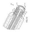
- FIG. 10illustrates an injector-igniter 1000 incorporating adaptive swirl injection and ignition technology according to a second exemplary embodiment similar in certain ways to that described above with respect to FIGS. 1-4B ; however, this embodiment, provides one or more heat transfer systems for receiving and exchanging heat generated by compression of gases such as air or other oxidants in the combustion chamber and/or from combustion gases that are delivered into the annular space between electrodes 1014 , 1016 .
- This embodimentincludes two systems, 1008 and 1010 , for such heat transfer and exchange operations.
- Heat transfer system 1010is a tubular sleeve that serves as a thermal capacitor to receive heat from higher temperature gases that periodically flow through the annular space between electrode 1016 and the inside surface of 1010 .
- System 1010may include one or more layers of thermal insulation and/or serve within another suitable heat dam such as an annular gap between 1010 and surrounding structure 1012 .
- system 1010further provides electrical conduction for production of ions during or in conjunction with the Lorentz thrusting processes.
- system 1010may include a dielectric material in certain zones to facilitate corona production and ignition operations. Suitable materials for system 1010 include various super-alloys, silicon carbide, aluminum nitride and other selections that are able to provide long life with abrupt temperature cycling in oxidizing and/or reducing gases. System 1010 performs new functions that integrate zones of heat transfer in electrically conductive and electrically insulating functions along with thermal conduction and radiation enhancing heat transfers.
- system 1010may include conductor materials and/or structures as known to those of skill in the art, such as those features disclosed in U.S. Pat. Nos. 4,770,953; 4,659,611; 4,649,070; 4,591,537; 4,618,592; 6,017,485; and 6,096,414, all of which are incorporated herein by reference in their entireties.
- Heat transfer system 1008can be of any suitable configuration to accomplish the purposes such as depicted by the embodiment shown in FIG. 10 .
- the heat transfer system 1008also function as a ferrule for attaching the electrode 1016 to conductor tube 1028 .
- system 1008is produced as a graphite-based or silicon carbide composite or from fibers, filaments, or powder that is compacted and sintered of suitable super-alloy and/or a selected ceramic composition. Ion production between electrode 1016 and adjacent surface areas of system 1010 may be enhanced by enrichment with substances such as aluminum or aluminum containing compounds that reduce the energy required for such local ion production.
- heat transfer systems 1008 and/or 1010periodically receive heat from hot gases such as compression and/or combustion gases and subsequently transfer such heat to fuel particles that are periodically transferred through the annular passageway from ports such as 1026 to the combustion chamber 1018 .
- the heat transfer systems 1008 , 1010serve as a type of thermal flywheel to regenerate the heat absorbed during compression and/or combustion. In some embodiments, this enables sufficient activation of various fuel selections to combust with little or no expenditure of electrical energy for ignition events.
- fuel selectionssuch as diethyl ether (DEE), dimethyl ether (DME) and other chemical plasma agents serve as combustion initiators and/or accelerants when utilized individually, in mixtures, or in blends with other fuels such as hydrogen, methane, ethane, propane, butane, ammonia and various fuel alcohols.
- Chemical plasma agentsare detailed further in my co-pending U.S. patent application Ser. No. 13/844,240, entitled “FUEL INJECTION SYSTEMS WITH ENHANCED THRUST,” and filed on Mar. 15, 2013, the disclosure of which is hereby incorporated by reference in its entirety.
- the amount of heat added to fuel particles passing through the space between systems 1008 and 1010can be reduced by Lorentz thrusting of oxidant during the compression stroke to reduce or limit the heat gain that is stored and thus the amount of heat that is subsequently transferred to the fuel particles. Heat transfer can also be enhanced by the amount of swirl and turbulent flow past such heat transfer surfaces in response to the variable pressure drop and/or adaptive Lorentz thrusting.
- control and operational permutationsinclude combinations of variable fuel pressure, variable duration of the open time of the fuel control valve, variable duration of the time between fuel valve openings, variable current development and resulting population of oxidant ions that are thrust into the combustion chamber, variable current development and resulting population of fuel ions, the velocity and included angle of entry at which such fuel particles are thrust into the combustion chamber, variable field strength and frequency of corona ignition, and variable activation temperature of fuel constituents that are heated by inline heat exchange systems.
- FIG. 11illustrates an injector-igniter 1102 incorporating adaptive swirl injection and ignition technology according to a third representative embodiment.
- Injector-igniter 1102includes an outwardly opening fuel valve 1105 for utilization of less-expensive alternative fuels in diesel engines that enable production of equal power and fuel efficiency by adaptive injection patterns and ignition timing comprised of various variable combinations.
- Such variablesinclude fuel pressure, Lorentz thrusting, and corona ignition.
- the pressure of alternative fuel delivered through fitting 1104is controlled by pressure regulator 1103 and the ignition characteristics are adjusted to produce adequate fuel penetration to rapidly complete fuel combustion within an insulative envelope of excess air. This provides optimized air functionality including rapid oxidation of one or more injection bursts of stratified fuel.
- Lorentz thrusting of fuel and/or oxidant particlesis achieved by application of sufficient electric field strength (voltage) through cable 1106 to initially develop an ion path between electrodes 1110 and 1112 .
- This conductive ion pathcauses the resistance to drop and an avalanche of additional ions are produced as a current which experiences Lorentz acceleration along the annular gap between electrodes 1112 and 1110 as shown.
- This Lorentz thrusting processmay be provided during intake, compression, or power strokes.
- the Lorentz thrustingmay be provided as during intake to produce cleaning, detectable ion current patterns or other actions by activated oxidants or later during compression as the piston nears or passes top dead center (TDC) to produce activated oxidants such as O 3 , NO x , OH ⁇ , and various other ions and/or radicals that are projected into the combustion chamber as a stratified charge of activated oxidants.
- TDCtop dead center
- Subsequent Lorentz acceleration of fuel particlesform ions to produce current between the surface along electrodes 1110 and electrode 1112 that thrust such current one or more successive times at adaptively adjusted durations and/or intervals between injections into the combustion chamber near TDC and during the power stroke to utilize such stratified activated oxidants along with other oxidants to greatly accelerate the beginning and completion of combustion events to adaptively adjust torque to match load.
- Corona ignitionis produced by application of high voltage through cable 1108 to charge capacitor 1118 which rapidly discharges for a duration sufficiently small to prevent ionization of the particles between electrode zones 1114 and 1116 and thereby cause projected corona streamers 1120 to be produced within the combustion chamber and cause many more locations of combustion initiation at a multitude of distances into the combustion chamber. Ions previously provided in the combustion chamber by ion thrusting and/or chemical oxidation provide much greater corona discharge efficiency including production energy and resulting acceleration of ignition and completion of combustion process events.
- Outwardly opening valve 1105is normally closed in response to force exerted by permanent magnet 1107 on armature 1109 and thus on the tubular stem 1115 of valve 1105 , which also serves as the journal bearing for axial motions of armatures 1109 and 1111 .
- Armature 1109closes valve 1105 and armature 1111 opens valve 1105 after gaining kinetic energy during free acceleration before impacting the end of adjustable free travel to quickly transfer kinetic energy to valve 1105 and armature 1109 and thus open valve 1105 for fuel flow into the combustion chamber. Opening of valve 1105 may be repeated numerous times near or after TDC to present multi-bursts of high surface to volume stratified charge fuel injections.
- Opening of valve 1105is aided by increased fuel pressure compared to compression pressure and closing of valve 1105 is aided by the pressure produced by combustion and along with the kinetic energy development and delivery system by armatures 1109 and 1111 enables very rapid fuel injection operations, which may be further adaptively modified by one or more Lorentz accelerations to produce additional sub-bursts of injected fuel with even greater surface-to-volume ratios.
- combustion pressure waves coupled with resonant openingenables very rapid closing and opening motions of valve 1105 .
- further acceleration of closing and opening of valve 1105is provided by resonant coupling of Lorentz thrusting and/or corona discharge cycling.
- valve 1105Such operations of valve 1105 include complete and partial opening events to produce discrete bursts or flows of more and less dense particle distributions. Particle penetrations into the combustion chamber thus include variations in the included angle of entry, velocity of entry, particle density adjustments, and extents of penetration to maximize air-utilization efficiency in operational modes including idle, acceleration, cruise and full power. Adaptive application of corona ignition may further be utilized to provide extremely rapid beginning and completion of fuel combustion for an extremely wide variety of fuel selections and modes of engine operation. Selection of such adaptive operational adjustments is made in response to instrumentation such as combustion chamber monitoring communicated to controller 1119 by optical cable 1117 , which is sealed within a small bore of valve 1105 and valve stem 1115 .
- FIG. 12illustrates an injector-igniter 1250 incorporating adaptive swirl injection and ignition technology according to a fourth representative embodiment.
- Injector-igniter 1250is adaptively controlled by microcomputer or processor 1251 and includes an inwardly opening fuel control valve 1252 , which is quickly opened against fuel pressure by transfer of kinetic energy from armature 1254 through cap 1257 to the head of valve 1252 .
- Valve stem 1256serves as a linear motion bearing and kinetic energy transfer guide component for armature 1254 .
- armature 1254accelerates through free travel FT, and transfers kinetic energy through cap 1257 to valve 1252 as it continues to complete the adjustable linear travel TT to open valve 1252 the distance TT-FT. Adjustment of travel TT may be accomplished by axial positioning of pole-piece 1255 in response to manual or motorized inward or outward motion such as turning of thread assembly 1259 as shown.
- Fluid flow to control valve 1252may be provided through any number of passageways provided through embodiment 1250 and may include fuel and/or coolant flow through suitable entry passages for one or more fluids, such as annular and/or radial passageway arrangements such as partially depicted by 1264 , 1268 , and/or 1272 to cool the electromagnet assembly.
- valve 1252In operation rapid opening of valve 1252 is provided by transfer of kinetic energy gained by adjustable free motion acceleration of armature 1254 and rapid closure of valve 1252 is provided by a suitable spring 1253 and/or magnet 1258 , which is aided by force on valve 1252 produced by the fuel pressure difference compared to the combustion chamber pressure.
- Fuel injection into the combustion chamberis through passageways 1296 , 1298 and a pattern of slots or holes to produce the desired included angle for stratified charge delivery of fuel bursts pattern 1290 .
- passageways for pattern 1290may be angled or otherwise volute to induce swirl in the injected fuel and/or coolant pattern.
- the angle of slots or holes for pattern 1290may be tuned for a given application to provide radial, counter-rotating, or sympathetic patterns for entry into the combustion chamber.
- This adaptive single or multi-burst fuel injection systemmay be used in combination with Lorentz and/or corona ignition.
- adaptively projected corona ignition 1261is produced and emitted in response to the field established from electrodes 1292 and 1294 at an energy expenditure magnitude and frequency that suitably achieves the desired penetration and pattern of fuel bursts and corona ignition events for assured acceleration and completion of fuel combustion according to optimization of air functionality as monitored by instrumentation fibers 1260 for control by controller 1251 , including rapid oxidation of one or more injection bursts of stratified fuel, insulation of the heat released by fuel combustion, and expansive conversion of heat released by combustion into work.
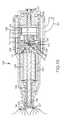
- FIG. 13illustrates an injector-igniter 1302 incorporating adaptive swirl injection and ignition technology according to a fifth representative embodiment.
- Injector-igniter 1302may be suitable for various purposes including combined heat and power (CHP) applications and/or for other purposes that use relatively low pressure fuels such as methane, hydrogen, carbon monoxide, methanol, or ethanol as may be provided by anaerobic digestion and/or destructive distillation and/or other dissociation or electrolysis processes.
- CHPcombined heat and power
- low pressure fuelenters injector-igniter 1302 through a suitable conduit such as 1304 and is transferred internally through various sub-circuits to provide cooling of magnet wire windings 1318 and 1314 along with winding 1306 on armature 1310 .
- Armature 1310is aligned and supported for low-friction axial reciprocation on piston 1320 and also acts as a fluid displacement piston. Armature 1310 is accelerated by electromagnetic armature 1310 as it is forced away from electromagnet or permanent magnet 1308 as shown.
- Fuel control valve 1336is opened in response to the force generated by a suitable actuator such as a pneumatic, hydraulic, piezoelectric, magnetostrictive, or electromagnet system.
- a suitable actuatorsuch as a pneumatic, hydraulic, piezoelectric, magnetostrictive, or electromagnet system.
- armature 1328is accelerated on bearing pin 1334 of valve 1336 and develops kinetic energy that is transferred upon reaching a motion stop or step on pin 1334 to quickly open valve 1336 .
- Armature 1328is returned by magnet 1332 and/or spring 1330 to restore valve 1336 to the normally closed position.
- armature 1310reciprocates axially and exerts force through attached piston 1320 to pressurize fluid delivered from conduit 1304 , through the various cooling routes to one or more suitable collector circuits and past check valves such as 1324 , 1342 ′ and/or 1326 . Subsequently pressurized fluid passes through check valve 1340 and conduit 1342 to storage in zones 1338 and 1344 . Pressurization of storage zones such as 1338 and 1344 may be by more or less continuous operation of fluid-cooled pump assembly 1306 , 1308 , 1310 , 1320 , 1342 and 1342 ′.
- the cycle frequency and stroke of armature 1310 and thus pressurization by displacement piston 1320may be adaptively adjusted to optimize the energy expended for pressurization and/or storage operations by axial motion of the assembly including suitable axial displacement such as by screw drive 1307 and permanent magnet 1308 in response to controller 1305 .
- Such acceleration of armature 1310may be in both forward and return motions according to the principles known to those of skill in the art and disclosed in U.S. Pat. Nos. 7,129,824; 5,327,120; and U.S. Patent Publication No. 2012/0095435, all of which are incorporated herein by reference in their entireties. This provides adaptive adjustments for very rapid pressurization to meet full power requirements along with lower frequency energy saving modes of operation to meet idle and low power needs.
- heating and thermal activation of fuelsmay be provided by resistive or inductive heating through elements such as 1315 , depicted in storage zone 1338 , in zone 1344 , and other fuel transfer pathways.
- Such heating for beneficial fuel activationmay include energy conversion of off-peak application of surplus heat and/or electricity from CHP operations, along with energy from engine deceleration, regenerative vehicle braking, regenerative utilization of fly-back energy from windings such as 1306 and/or 1314 and/or 1318 , heat transfers by conduction from combustion chamber gases or by thermoelectric generation.
- Electrodes 1317 and/or 1319may have similar clockwise or counterclockwise fin and channel structures in opposing surfaces that are similar to electrode features shown in FIGS. 3A-4B and may be constructed of magnetic materials, have permanent magnets incorporated as composited components and/or include incorporated or superimposed electromagnets. Such features enable production of a wide range of fuel entry patterns in combustion chamber 1348 .
- the pole orientations and field patterns of such magnetscan provide forces to initially accelerate ions toward the center of the combustion chamber 1348 and larger included angles can be adaptively produced by adjustments in fuel injection by pressure drop and/or electromagnetic shaping and/or electrode feature shaping, and/or Lorentz thrusting away from or within the pattern shown as 1346 .
- Computer 1305controls the temperature that is maintained for such beneficial activation and limits the upper temperature to prevent deposition of fuel residue and/or other precipitates due to thermal degradation.
- Such control of fuel temperatureextends to the fluid dynamics developed in the flow through swirl passages such as 1321 through electrode 1317 and by shaping interactions with fins and/or channels to produce the desired expansion of launch vectors into combustion chamber 1348 .
- Thisprovides a wide variation of the included angle of fuel ion and swept fuel vectors from magnetic focus 1346 to increased swirl separation to produce array 1346 as a result of increased pressure drop and/or increased current magnitude between electrodes 1317 and 1319 to greater included angle arrays as may be varied within angle 1346 as shown commensurate with the greatest pressure drop and/or increased current between electrodes 1317 and 1319 .
- FIG. 14illustrates an injector-igniter 1450 incorporating adaptive swirl injection and ignition technology according to a sixth representative embodiment.
- Injector-igniter 1450may be particularly well suited to enable various modes of operation including CHP applications that provide for anaerobic digestion, thermal dissociation and/or destructive distillation of energy crops and/or organic wastes to produce low pressure fuel constituents that are pressurized by a hydraulic pressurized compressor-pump using hermetically sealed bellows or diaphragm 1460 that is axially extended by cyclic pressure.
- Such pressuremay be supplied by a suitable source such as the engine's oil and/or fuel pump to supplement or provide the axial force to piston 1420 or to do so in conjunction with the electromagnetic force generating system including electromagnet or permanent magnet 1408 , electromagnetic magnetic winding 1406 on armature 1410 .
- Reciprocation of piston 1420may be forced by cyclic hydraulic pressurization and depressurization of hermetically sealed diaphragm 1460 and may be applied by suitable valve action or by the primary pump cycle as may be provided through one or more conduits such as 1464 from suitable fittings such as 1462 .
- Such hydraulic alternative fuel pressurization combined with electrically driven solenoid pressurizationenables the electrical system to provide pressurized fuel for rapid startups with low pressure fuel sources. Subsequently, hydraulic pressurization can provide rapid development of optimum pressure along with load matching to efficiently meet power and performance requirements.
- diesel engineshave cam-driven piston pumps to pressurize lubricating oil and similar, but much higher pressure, fuel pumps for direct injection.
- One or both of these pumpscan be utilized such as by application of the low pressure from the lubricating oil pump for the first stage of alternative fuel compression and if desired subsequent further compression to achieve much higher pressure storage in zones 1438 and 1444 by cyclic pressure supplied by the fuel pump.
- diaphragmssuch as 1460 along with their associated pistons 1420 and valves 1426 and 1440 and others as may be suitable for various internal passageway circuits along with heat exchanger 1411 to cool the compressed gases can be located within injector 1450 or in another suitable housing (not shown) to facilitate repair, maintenance, and heat removal.
- Typical in-line or rotary diesel injector pumpsoperate at cam speed and produce 20,000 to 30,000 PSIG pressure and provide excellent matching of the alternative fuel flow with power demands.
- the oil exiting the compressor drive pumpcan be directed to lubricate relative motion components of the engine including the valve train, piston, cam, and crank shaft, etc.
- Re-purposing the high pressure fuel pumpby converting it from diesel fuel pressurization service to gaseous fuel pressurization with the present ignition systems allows the diesel fuel pump to operate with much less wear and fatigue stress at lower power requirements for adequate pressurization of gaseous fuels.
- operation at 20,000 to 30,000 PSI for diesel fuel pressurizationcan be relaxed to 800 to 2,800 PSI for adequate pressurization of gaseous fuels in conjunction with the present combustant activation and ignition systems.
- Pressurized fuel stored in zones such as 1438 and 1444can be adaptively heated by suitable heaters such as 1415 to increase the pressure and/or activation status for expedited ignition and combustion. Further heating from combustion chamber gases through heat exchange facilitated by high surface to volume electrode features 1456 , 1453 , and 1452 enable additional collection and transfer of activation energy.
- Thermal and/or high pressure whistle or ultrasonic injectionactivates many fuel selections such as DEE, DME, carbazoles, and/or various additives sufficiently to combust upon injection and penetration of compressed oxidant. Additional Lorentz acceleration of ion currents initiated by electrode points 1452 and that are thrust toward the combustion chamber as current rapidly builds between electrodes 1453 and 1456 provides another activation and ignition choice in the adaptive engine operation.
- Projected corona ionization and ignitionis provided when the sufficiently rapid rate of electric field establishment to or from electrodes 1456 to exceed the rate for forming spark type discharge.
- Such more efficient corona dischargeis shaped to occur in the pattern of the swirl induced ion and/or fuel particle vector projections within included angle 1461 within the combustion chamber. This provides efficient utilization of electrical energy to accomplish accelerated stratified charge combustion.
- Adaptively selected ignition systemsinclude oxidant activation by Lorentz and/or corona systems to provide stratified inventories of ozone, NO x and/or other ions for igniting and fully oxidizing fuel as it injected, similar oxidant activation and injection of fuel particle ions that are produced by thermal, corona and/or Lorentz systems, and direct injection of fuel particle ions and/or other activation states that are produced by thermal, acoustic, corona and/or Lorentz systems.
- Adaptive generation of highly activated oxidants such as ozone (O 3 ) and/or NO x in the combustion chamber by spark ionization or corona discharge from electrodes 1456 and/or 1453greatly accelerates the beginning and completion of combustion.
- adaptive production of activated oxidants such as ozone and/or NO xmay be timed to begin at an optimized crank angle and may continue for an adaptively determined period and frequency to meet torque and performance needs in accordance with fuel ignition and combustion activation by heating, corona, or other ignition systems.
- one or more bursts 1446 of pressurized fuelenter fuel distribution channels 1459 through passageway 1457 and are injected within the combustion chamber oxidant to undergo accelerated ignition of such fuel by activated oxidant and/or whistle or ultrasonic activation and/or by Lorentz and/or corona discharge emitted throughout the stratified fuel-oxidant mixtures that result.
- the methodcomprises introducing the fuel into an annular region between two electrodes; providing a current across the two electrodes and through the fuel to establish a plasma; maintaining the current across the two electrodes to establish Lorentz forces driving the plasma from the annular region and into the combustion chamber; and imparting rotation on the fuel and plasma as it is driven from the annular region.
- the methodfurther comprises applying a rapid application of voltage to the two electrodes whereby ionization between the two electrodes is avoided, thereby causing a corona discharge to extend into the combustion chamber.
- the combustion chambercontains a rotating oxidant and the rotation of the fuel and plasma is counter to the rotating oxidant.
- the rotation of the fuel and plasmais the same direction as the rotating oxidant.
- the rotation of the fuel and plasmais imparted via a plurality of flow shaping features disposed on at least one of the two electrodes. In other embodiments the rotation is induced by a magnetic field.
- a fuel injector-ignitercomprising:
- valveincluding a valve head operative to open and close against a valve seat in response to activation of the actuator;
- valve seatincludes an electrode portion extending beyond the valve head and within the housing to form at least one gap
- a current discharge between the housing and electrode portionestablishes a plasma and electro-magnetic forces driving the plasma from the at least one gap.
- a fuel injector-ignitercomprising:
- valve seat electrodeincluding a valve seat and an electrode portion extending beyond the valve seat and within the housing to form an annular gap
- valveincluding a valve head operative to open and close against the valve seat in response to activation of the actuator;
- the power supplyis operative to produce a current discharge between the housing and electrode portion establishing a plasma and electromagnetic forces driving the plasma from the annular gap.
- a method of injecting and igniting fuel in a combustion chambercomprising:
Landscapes
- Engineering & Computer Science (AREA)
- Chemical & Material Sciences (AREA)
- Combustion & Propulsion (AREA)
- Mechanical Engineering (AREA)
- General Engineering & Computer Science (AREA)
- Physics & Mathematics (AREA)
- Electromagnetism (AREA)
- Optics & Photonics (AREA)
- Ignition Installations For Internal Combustion Engines (AREA)
- Fuel-Injection Apparatus (AREA)
- Plasma & Fusion (AREA)
Abstract
Description
Claims (16)
Priority Applications (6)
| Application Number | Priority Date | Filing Date | Title |
|---|---|---|---|
| US13/797,753US8800527B2 (en) | 2012-11-19 | 2013-03-12 | Method and apparatus for providing adaptive swirl injection and ignition |
| KR1020157016554AKR20150086368A (en) | 2012-11-19 | 2013-11-19 | Method and apparatus for providing adaptive swirl injection and ignition |
| PCT/US2013/070710WO2014078835A2 (en) | 2012-11-19 | 2013-11-19 | Method and apparatus for providing adaptive swirl injection and ignition |
| EP13854637.9AEP2920453A4 (en) | 2012-11-19 | 2013-11-19 | Method and apparatus for providing adaptive swirl injection and ignition |
| CN201380070880.3ACN105308306A (en) | 2012-11-19 | 2013-11-19 | Method and apparatus for providing adaptive swirl injection and ignition |
| US14/331,765US20150075486A1 (en) | 2012-11-19 | 2014-07-15 | Method and apparatus for providing adaptive swirl injection and ignition |
Applications Claiming Priority (2)
| Application Number | Priority Date | Filing Date | Title |
|---|---|---|---|
| US201261728157P | 2012-11-19 | 2012-11-19 | |
| US13/797,753US8800527B2 (en) | 2012-11-19 | 2013-03-12 | Method and apparatus for providing adaptive swirl injection and ignition |
Related Child Applications (1)
| Application Number | Title | Priority Date | Filing Date |
|---|---|---|---|
| US14/331,765ContinuationUS20150075486A1 (en) | 2012-11-19 | 2014-07-15 | Method and apparatus for providing adaptive swirl injection and ignition |
Publications (2)
| Publication Number | Publication Date |
|---|---|
| US20140137840A1 US20140137840A1 (en) | 2014-05-22 |
| US8800527B2true US8800527B2 (en) | 2014-08-12 |
Family
ID=50726731
Family Applications (2)
| Application Number | Title | Priority Date | Filing Date |
|---|---|---|---|
| US13/797,753Expired - Fee RelatedUS8800527B2 (en) | 2012-11-19 | 2013-03-12 | Method and apparatus for providing adaptive swirl injection and ignition |
| US14/331,765AbandonedUS20150075486A1 (en) | 2012-11-19 | 2014-07-15 | Method and apparatus for providing adaptive swirl injection and ignition |
Family Applications After (1)
| Application Number | Title | Priority Date | Filing Date |
|---|---|---|---|
| US14/331,765AbandonedUS20150075486A1 (en) | 2012-11-19 | 2014-07-15 | Method and apparatus for providing adaptive swirl injection and ignition |
Country Status (5)
| Country | Link |
|---|---|
| US (2) | US8800527B2 (en) |
| EP (1) | EP2920453A4 (en) |
| KR (1) | KR20150086368A (en) |
| CN (1) | CN105308306A (en) |
| WO (1) | WO2014078835A2 (en) |
Cited By (19)
| Publication number | Priority date | Publication date | Assignee | Title |
|---|---|---|---|---|
| US20140090622A1 (en)* | 2012-09-28 | 2014-04-03 | Harold Cranmer Seelig | Internal combustion engine |
| US20160208756A1 (en)* | 2012-08-13 | 2016-07-21 | Mcalister Technologies, Llc | Injector-igniters with variable gap electrode |
| US9562500B2 (en) | 2013-03-15 | 2017-02-07 | Mcalister Technologies, Llc | Injector-igniter with fuel characterization |
| US20170335761A1 (en)* | 2014-11-12 | 2017-11-23 | Verail Technologies, Inc. | Multi-fuel internal combustion engine, fuel systems and related methods |
| US20190242333A1 (en)* | 2016-09-29 | 2019-08-08 | Jong Pyo PARK | Device for enhancing fuel efficiency |
| US10465629B2 (en) | 2017-03-30 | 2019-11-05 | Quest Engines, LLC | Internal combustion engine having piston with deflector channels and complementary cylinder head |
| US10526953B2 (en) | 2017-03-30 | 2020-01-07 | Quest Engines, LLC | Internal combustion engine |
| US10590834B2 (en) | 2017-03-30 | 2020-03-17 | Quest Engines, LLC | Internal combustion engine |
| US10590813B2 (en) | 2017-03-30 | 2020-03-17 | Quest Engines, LLC | Internal combustion engine |
| US10598285B2 (en) | 2017-03-30 | 2020-03-24 | Quest Engines, LLC | Piston sealing system |
| US10724428B2 (en) | 2017-04-28 | 2020-07-28 | Quest Engines, LLC | Variable volume chamber device |
| US10753267B2 (en) | 2018-01-26 | 2020-08-25 | Quest Engines, LLC | Method and apparatus for producing stratified streams |
| US10753308B2 (en) | 2017-03-30 | 2020-08-25 | Quest Engines, LLC | Internal combustion engine |
| US10808866B2 (en) | 2017-09-29 | 2020-10-20 | Quest Engines, LLC | Apparatus and methods for controlling the movement of matter |
| US10883498B2 (en) | 2017-05-04 | 2021-01-05 | Quest Engines, LLC | Variable volume chamber for interaction with a fluid |
| US10989138B2 (en) | 2017-03-30 | 2021-04-27 | Quest Engines, LLC | Internal combustion engine |
| US11041456B2 (en) | 2017-03-30 | 2021-06-22 | Quest Engines, LLC | Internal combustion engine |
| US11134335B2 (en) | 2018-01-26 | 2021-09-28 | Quest Engines, LLC | Audio source waveguide |
| US11770062B2 (en) | 2020-08-07 | 2023-09-26 | Apple Inc. | Liquid heat exchanger for electronic device |
Families Citing this family (21)
| Publication number | Priority date | Publication date | Assignee | Title |
|---|---|---|---|---|
| US9476347B2 (en) | 2010-11-23 | 2016-10-25 | Woodward, Inc. | Controlled spark ignited flame kernel flow in fuel-fed prechambers |
| US8584648B2 (en) | 2010-11-23 | 2013-11-19 | Woodward, Inc. | Controlled spark ignited flame kernel flow |
| US9172217B2 (en) | 2010-11-23 | 2015-10-27 | Woodward, Inc. | Pre-chamber spark plug with tubular electrode and method of manufacturing same |
| JP5421952B2 (en)* | 2011-04-12 | 2014-02-19 | 日本特殊陶業株式会社 | Ignition system |
| EP2935866B8 (en)* | 2012-12-21 | 2019-05-22 | Federal-Mogul Ignition LLC | Intra-event control strategy for corona ignition systems |
| US9856848B2 (en) | 2013-01-08 | 2018-01-02 | Woodward, Inc. | Quiescent chamber hot gas igniter |
| US9765682B2 (en) | 2013-06-10 | 2017-09-19 | Woodward, Inc. | Multi-chamber igniter |
| US20170248109A1 (en)* | 2014-05-29 | 2017-08-31 | Imagineering, Inc. | Injector having in-built ignition system |
| WO2016070888A1 (en)* | 2014-11-06 | 2016-05-12 | Volvo Truck Corporation | An in a fuel injector integrated corona igniter |
| CN104500185A (en)* | 2014-12-12 | 2015-04-08 | 李可文 | Diesel engine tail gas reducing agent as well as application and preparation method thereof |
| US9653886B2 (en) | 2015-03-20 | 2017-05-16 | Woodward, Inc. | Cap shielded ignition system |
| JP6580701B2 (en) | 2015-03-20 | 2019-09-25 | ウッドワード, インコーポレーテッドWoodward, Inc. | Parallel pre-combustion chamber ignition system |
| US9890689B2 (en)* | 2015-10-29 | 2018-02-13 | Woodward, Inc. | Gaseous fuel combustion |
| GB201521184D0 (en)* | 2015-12-01 | 2016-01-13 | Delphi Internat Operations Luxembourg S À R L | Gaseous fuel injectors |
| US10118696B1 (en) | 2016-03-31 | 2018-11-06 | Steven M. Hoffberg | Steerable rotating projectile |
| US20180171890A1 (en)* | 2016-12-20 | 2018-06-21 | Council Of Scientific & Industrial Research | Dual Fumigation Homogeneous Charge Compression Ignition (DF-HCCI) Engine |
| US11712637B1 (en) | 2018-03-23 | 2023-08-01 | Steven M. Hoffberg | Steerable disk or ball |
| US11739937B2 (en) | 2020-02-11 | 2023-08-29 | University Of Notre Dame Du Lac | Plasma injection modules |
| CN111765032B (en)* | 2020-06-12 | 2022-06-14 | 沈阳航空航天大学 | Sliding arc plasma-high disturbance cross structure fuel oil atomizing nozzle |
| WO2024206661A2 (en)* | 2023-03-28 | 2024-10-03 | Regents Of The University Of Minnesota | Ammonia pre-chamber internal combustion engine |
| CN119755669B (en)* | 2024-12-30 | 2025-09-26 | 哈尔滨理工大学 | Vortex type plasma igniter capable of preventing electrode ablation based on vortex airflow discharge |
Citations (243)
| Publication number | Priority date | Publication date | Assignee | Title |
|---|---|---|---|---|
| US1307088A (en) | 1919-06-17 | X- s spark-plug | ||
| US1451384A (en) | 1920-04-19 | 1923-04-10 | Whyte John | Solenoid-controlled fuel injection and ignition valve |
| US1765237A (en) | 1928-02-17 | 1930-06-17 | Fred H King | Triple-cam-drive gasoline engine |
| US2255203A (en) | 1940-02-28 | 1941-09-09 | Wright Aeronautical Corp | Fuel injection spark plug |
| US2681212A (en) | 1951-05-16 | 1954-06-15 | Fenley Thomas Douglas | Dual fuel carburetion |
| US2744507A (en)* | 1951-02-07 | 1956-05-08 | Inconex Handelsges M B H Fur I | Means for treating liquid fuel before its injection into the working cylinder of internal combustion engines |
| US2864974A (en) | 1954-10-19 | 1958-12-16 | Smitsvonk N V Res Laboratorieu | Ignition system for internal combustion engines |
| US3058453A (en) | 1960-02-15 | 1962-10-16 | Walker Mfg Co | Fuel injector-igniter |
| US3060912A (en) | 1960-02-15 | 1962-10-30 | Walker Mfg Co | Fuel injector-igniter |
| US3081758A (en) | 1960-05-02 | 1963-03-19 | Walker Mfg Co | Pressure actuated fuel injector |
| US3243335A (en) | 1963-03-13 | 1966-03-29 | Samuel P Faile | Ceramic product and process of producing it |
| GB1038490A (en) | 1963-02-18 | 1966-08-10 | Papst Hermann | Fuel injection nozzles for internal combustion engines |
| US3373724A (en) | 1964-02-10 | 1968-03-19 | Papst Hermann | Fuel injection and ignition device for internal combustion engines |
| US3520961A (en) | 1967-05-12 | 1970-07-21 | Yuken Ind Co Ltd | Method for manufacturing ceramic articles |
| US3551738A (en) | 1969-01-30 | 1970-12-29 | Westinghouse Electric Corp | Condenser discharge lamp circuit with a pulse forming network and a keep alive circuit |
| US3594877A (en) | 1969-10-24 | 1971-07-27 | Yuken Kogyo Co Ltd | Apparatus for manufacturing ceramic articles |
| US3608050A (en) | 1969-09-12 | 1971-09-21 | Union Carbide Corp | Production of single crystal sapphire by carefully controlled cooling from a melt of alumina |
| US3689293A (en) | 1970-07-08 | 1972-09-05 | Corning Glass Works | Mica glass-ceramics |
| US3866074A (en)* | 1973-07-23 | 1975-02-11 | David A Smith | Magnetic spark spreader |
| US3926169A (en) | 1974-06-21 | 1975-12-16 | Fuel Injection Dev Corp | Combined fuel vapor injector and igniter system for internal combustion engines |
| US3931438A (en) | 1971-11-08 | 1976-01-06 | Corning Glass Works | Differential densification strengthening of glass-ceramics |
| US3960995A (en) | 1970-05-13 | 1976-06-01 | Kourkene Jacques P | Method for prestressing a body of ceramic material |
| US3976039A (en) | 1973-06-06 | 1976-08-24 | Regie Nationale Des Usines Renault | Internal combustion engine with stratified charge |
| US3997352A (en) | 1975-09-29 | 1976-12-14 | Corning Glass Works | Mica-spodumene glass-ceramic articles |
| US4066046A (en) | 1974-07-29 | 1978-01-03 | Mcalister Roy E | Method and apparatus for fuel injection-spark ignition system for an internal combustion engine |
| US4087719A (en)* | 1976-03-04 | 1978-05-02 | Massachusetts Institute Of Technology | Spark plug |
| US4095580A (en) | 1976-10-22 | 1978-06-20 | The United States Of America As Represented By The United States Department Of Energy | Pulse-actuated fuel-injection spark plug |
| US4122816A (en) | 1976-04-01 | 1978-10-31 | The United States Of America As Represented By The Administrator Of The National Aeronautics And Space Administration | Plasma igniter for internal combustion engine |
| US4135481A (en) | 1976-11-26 | 1979-01-23 | Cornell Research Foundation, Inc. | Exhaust gas recirculation pre-stratified charge |
| US4203393A (en) | 1979-01-04 | 1980-05-20 | Ford Motor Company | Plasma jet ignition engine and method |
| US4330732A (en) | 1980-03-14 | 1982-05-18 | Purification Sciences Inc. | Plasma ceramic coating to supply uniform sparking action in combustion engines |
| US4332223A (en) | 1980-08-29 | 1982-06-01 | Dalton James M | Plasma fuel ignitors |
| US4364342A (en) | 1980-10-01 | 1982-12-21 | Ford Motor Company | Ignition system employing plasma spray |
| US4377455A (en) | 1981-07-22 | 1983-03-22 | Olin Corporation | V-Shaped sandwich-type cell with reticulate electodes |
| US4381740A (en) | 1980-05-05 | 1983-05-03 | Crocker Alfred J | Reciprocating engine |
| US4382189A (en) | 1979-05-25 | 1983-05-03 | Wilson John B | Hydrogen supplemented diesel electric locomotive |
| US4448160A (en) | 1982-03-15 | 1984-05-15 | Vosper George W | Fuel injector |
| US4469160A (en) | 1981-12-23 | 1984-09-04 | United Technologies Corporation | Single crystal solidification using multiple seeds |
| US4483485A (en) | 1981-12-11 | 1984-11-20 | Aisan Kogyo kabuskiki Kaisha | Electromagnetic fuel injector |
| US4511612A (en) | 1981-08-21 | 1985-04-16 | Motoren-Und Turbinen-Union Munchen Gmbh | Multiple-layer wall for a hollow body and method for manufacturing same |
| US4528270A (en) | 1982-11-02 | 1985-07-09 | Kabushiki Kaisya Advance Kaihatsu Kenkyujo | Electrochemical method for detection and classification of microbial cell |
| US4536452A (en) | 1983-10-24 | 1985-08-20 | Corning Glass Works | Spontaneously-formed machinable glass-ceramics |
| US4567857A (en) | 1980-02-26 | 1986-02-04 | The United States Of America As Represented By The Administrator Of The National Aeronautics And Space Administration | Combustion engine system |
| US4574037A (en) | 1983-04-12 | 1986-03-04 | Kanegafuchi Kagaku Kogyo Kabushiki Kaisha | Vertical type electrolytic cell and electrolytic process using the same |
| DE3443022A1 (en) | 1984-11-26 | 1986-05-28 | Walter Neumarkt am Wallersee Dolzer | Transistor ignition system |
| US4677960A (en) | 1984-12-31 | 1987-07-07 | Combustion Electromagnetics, Inc. | High efficiency voltage doubling ignition coil for CD system producing pulsed plasma type ignition |
| US4688538A (en) | 1984-12-31 | 1987-08-25 | Combustion Electromagnetics, Inc. | Rapid pulsed multiple pulse ignition and high efficiency power inverter with controlled output characteristics |
| US4733646A (en) | 1986-04-30 | 1988-03-29 | Aisin Seiki Kabushiki Kaisha | Automotive ignition systems |
| US4736718A (en) | 1987-03-19 | 1988-04-12 | Linder Henry C | Combustion control system for internal combustion engines |
| US4742265A (en) | 1986-11-12 | 1988-05-03 | Ford Motor Company | Spark plug center electrode of alloy material including aluminum and chromium |
| US4760820A (en) | 1983-07-20 | 1988-08-02 | Luigi Tozzi | Plasma jet ignition apparatus |
| US4760818A (en) | 1986-12-16 | 1988-08-02 | Allied Corporation | Vapor phase injector |
| US4774914A (en) | 1985-09-24 | 1988-10-04 | Combustion Electromagnetics, Inc. | Electromagnetic ignition--an ignition system producing a large size and intense capacitive and inductive spark with an intense electromagnetic field feeding the spark |
| US4774919A (en) | 1986-09-08 | 1988-10-04 | Yamaha Hatsudoki Kabushiki Kaisha | Combustion chamber importing system for two-cycle diesel engine |
| US4834033A (en) | 1986-10-31 | 1989-05-30 | Larsen Melvin J | Apparatus and method for a balanced internal combustion engine coupled to a drive shaft |
| US4841925A (en)* | 1986-12-22 | 1989-06-27 | Combustion Electromagnetics, Inc. | Enhanced flame ignition for hydrocarbon fuels |
| US4922883A (en) | 1987-10-29 | 1990-05-08 | Aisin Seiki Kabushiki Kaisha | Multi spark ignition system |
| US4932263A (en) | 1989-06-26 | 1990-06-12 | General Motors Corporation | Temperature compensated fiber optic pressure sensor |
| US4967708A (en) | 1987-09-17 | 1990-11-06 | Robert Bosch Gmbh | Fuel injection valve |
| US4977873A (en) | 1989-06-08 | 1990-12-18 | Clifford L. Elmore | Timing chamber ignition method and apparatus |
| US4982708A (en) | 1989-06-22 | 1991-01-08 | Robert Bosch Gmbh | Fuel injection nozzle for internal combustion engines |
| US5034852A (en) | 1989-11-06 | 1991-07-23 | Raytheon Company | Gasket for a hollow core module |
| US5055435A (en) | 1987-03-24 | 1991-10-08 | Ngk Insulators, Ltd. | Ceramic materials to be insert-cast |
| US5056496A (en) | 1989-03-14 | 1991-10-15 | Nippondenso Co., Ltd. | Ignition system of multispark type |
| US5072617A (en) | 1990-10-30 | 1991-12-17 | The United States Of America As Represented By The United States Department Of Energy | Fiber-optic liquid level sensor |
| US5076223A (en) | 1990-03-30 | 1991-12-31 | Board Of Regents, The University Of Texas System | Miniature railgun engine ignitor |
| US5095742A (en) | 1990-08-24 | 1992-03-17 | Ford Motor Company | Determining crankshaft acceleration in an internal combustion engine |
| US5109817A (en) | 1990-11-13 | 1992-05-05 | Altronic, Inc. | Catalytic-compression timed ignition |
| US5131376A (en) | 1991-04-12 | 1992-07-21 | Combustion Electronics, Inc. | Distributorless capacitive discharge ignition system |
| US5193515A (en) | 1991-03-12 | 1993-03-16 | Aisin Seiki Kabushiki Kaisha | Ignition system for an engine |
| US5207208A (en) | 1991-09-06 | 1993-05-04 | Combustion Electromagnetics Inc. | Integrated converter high power CD ignition |
| US5211142A (en) | 1990-03-30 | 1993-05-18 | Board Of Regents, The University Of Texas System | Miniature railgun engine ignitor |
| US5220901A (en) | 1991-10-09 | 1993-06-22 | Mitsubishi Denki Kabushiki Kaisha | Capacitor discharge ignition system with inductively extended discharge time |
| US5267601A (en) | 1988-11-10 | 1993-12-07 | Lanxide Technology Company, Lp | Method for forming a metal matrix composite body by an outside-in spontaneous infiltration process, and products produced thereby |
| US5297518A (en) | 1992-08-10 | 1994-03-29 | Cherry Mark A | Mass controlled compression timed ignition method and igniter |
| US5305360A (en) | 1993-02-16 | 1994-04-19 | Westinghouse Electric Corp. | Process for decontaminating a nuclear reactor coolant system |
| US5328094A (en) | 1993-02-11 | 1994-07-12 | General Motors Corporation | Fuel injector and check valve |
| US5377633A (en) | 1993-07-12 | 1995-01-03 | Siemens Automotive L.P. | Railplug direct injector/ignitor assembly |
| US5390546A (en) | 1993-07-01 | 1995-02-21 | Wlodarczyk; Marek T. | Fiber optic diaphragm sensors for engine knock and misfire detection |
| US5392745A (en) | 1987-02-20 | 1995-02-28 | Servojet Electric Systems, Ltd. | Expanding cloud fuel injecting system |
| US5394838A (en) | 1992-07-24 | 1995-03-07 | American Fuel Systems, Inc. | Vaporized fuel injection system |
| US5421299A (en) | 1992-08-10 | 1995-06-06 | Cherry; Mark A. | Compression timed pre-chamber flame distributing igniter for internal combustion engines |
| US5421195A (en) | 1993-07-01 | 1995-06-06 | Wlodarczyk; Marek T. | Fiber optic microbend sensor for engine knock and misfire detection |
| US5435286A (en) | 1994-05-02 | 1995-07-25 | Cummins Engine Company, Inc. | Ball link assembly for vehicle engine drive trains |
| US5439532A (en) | 1992-06-30 | 1995-08-08 | Jx Crystals, Inc. | Cylindrical electric power generator using low bandgap thermophotovolatic cells and a regenerative hydrocarbon gas burner |
| US5456241A (en) | 1993-05-25 | 1995-10-10 | Combustion Electromagnetics, Inc. | Optimized high power high energy ignition system |
| US5475772A (en) | 1994-06-02 | 1995-12-12 | Honeywell Inc. | Spatial filter for improving polarization extinction ratio in a proton exchange wave guide device |
| US5497744A (en)* | 1993-11-29 | 1996-03-12 | Toyota Jidosha Kabushiki Kaisha | Fuel injector with an integrated spark plug for a direct injection type engine |
| US5517961A (en) | 1995-02-27 | 1996-05-21 | Combustion Electromagnetics, Inc. | Engine with flow coupled spark discharge |
| US5531199A (en) | 1992-05-11 | 1996-07-02 | United Fuels Limited | Internal combustion engines |
| US5549746A (en) | 1993-09-24 | 1996-08-27 | General Electric Company | Solid state thermal conversion of polycrystalline alumina to sapphire using a seed crystal |
| US5584490A (en) | 1994-08-04 | 1996-12-17 | Nippon Gasket Co., Ltd. | Metal gasket with coolant contact areas |
| US5588299A (en) | 1993-05-26 | 1996-12-31 | Simmonds Precision Engine Systems, Inc. | Electrostatic fuel injector body with igniter electrodes formed in the housing |
| US5605125A (en) | 1994-11-18 | 1997-02-25 | Yaoita; Yasuhito | Direct fuel injection stratified charge engine |
| US5607106A (en) | 1994-08-10 | 1997-03-04 | Cummins Engine Company | Low inertia, wear-resistant valve for engine fuel injection systems |
| US5662389A (en) | 1996-09-10 | 1997-09-02 | New York Air Brake Corporation | Variable load EP brake control system |
| US5676026A (en) | 1994-09-20 | 1997-10-14 | Honda Giken Kogyo Kabushiki Kaisha | Hydraulic pressure control system |
| US5694761A (en) | 1993-07-07 | 1997-12-09 | Griffin, Jr.; Arthur T. | Combustor cooling for gas turbine engines |
| US5699253A (en) | 1995-04-05 | 1997-12-16 | Ford Global Technologies, Inc. | Nonlinear dynamic transform for correction of crankshaft acceleration having torsional oscillations |
| US5702761A (en) | 1994-04-29 | 1997-12-30 | Mcdonnell Douglas Corporation | Surface protection of porous ceramic bodies |
| US5704321A (en) | 1996-05-29 | 1998-01-06 | The Trustees Of Princeton University | Traveling spark ignition system |
| US5715788A (en) | 1996-07-29 | 1998-02-10 | Cummins Engine Company, Inc. | Integrated fuel injector and ignitor assembly |
| US5738818A (en) | 1996-08-28 | 1998-04-14 | Northrop Grumman Corporation | Compression/injection molding of polymer-derived fiber reinforced ceramic matrix composite materials |
| US5746171A (en) | 1995-02-06 | 1998-05-05 | Yaoita; Yasuhito | Direct fuel injection stratified charge engine |
| US5767026A (en) | 1994-10-04 | 1998-06-16 | Agency Of Industrial Science And Technology | Silicon nitride ceramic and process for forming the same |
| US5797427A (en) | 1996-10-11 | 1998-08-25 | Buescher; Alfred J. | Fuel injector check valve |
| US5806581A (en) | 1995-12-21 | 1998-09-15 | Modine Manufacturing Company | Oil cooler with a retained, blow-out proof, and extrusion resistant gasket configuration |
| US5853175A (en) | 1996-09-30 | 1998-12-29 | Ishikawa Gasket Co., Ltd. | Cylinder head gasket with fluid flow path |
| US5863326A (en) | 1996-07-03 | 1999-01-26 | Cermet, Inc. | Pressurized skull crucible for crystal growth using the Czochralski technique |
| US5876659A (en) | 1993-06-25 | 1999-03-02 | Hitachi, Ltd. | Process for producing fiber reinforced composite |
| US5915272A (en) | 1993-08-02 | 1999-06-22 | Motorola Inc. | Method of detecting low compression pressure responsive to crankshaft acceleration measurement and apparatus therefor |
| US5941207A (en) | 1997-09-08 | 1999-08-24 | Ford Global Technologies, Inc. | Direct injection spark ignition engine |
| US5975032A (en) | 1996-06-07 | 1999-11-02 | Sanshin Kogyo Kabushiki Kaisha | Engine cooling system |
| US5975433A (en)* | 1996-11-08 | 1999-11-02 | Zexel Corporation | Fuel injection nozzle with rotary valve |
| US5983855A (en)* | 1996-09-18 | 1999-11-16 | Robert Bosch Gmbh | Fuel injection valve with integrated spark plug |
| US6017390A (en) | 1996-07-24 | 2000-01-25 | The Regents Of The University Of California | Growth of oriented crystals at polymerized membranes |
| US6026568A (en) | 1995-08-16 | 2000-02-22 | Northrop Grumman | High efficiency low-pollution engine |
| US6062498A (en) | 1998-04-27 | 2000-05-16 | Stanadyne Automotive Corp. | Fuel injector with at least one movable needle-guide |
| US6065692A (en)* | 1999-06-09 | 2000-05-23 | Siemens Automotive Corporation | Valve seat subassembly for fuel injector |
| US6081183A (en) | 1998-04-24 | 2000-06-27 | Eaton Corporation | Resistor adapted for use in forced ventilation dynamic braking applications |
| US6085990A (en) | 1997-01-22 | 2000-07-11 | Daimlerchrysler Ag | Piezoelectric injector for fuel-injection systems of internal combustion engines |
| US6092501A (en) | 1997-05-20 | 2000-07-25 | Nissan Motor Co., Ltd. | Direct injection gasoline engine with stratified charge combustion and homogeneous charge combustion |
| US6093338A (en) | 1997-08-21 | 2000-07-25 | Kabushiki Kaisha Toyota Chuo Kenkyusho | Crystal-oriented ceramics, piezoelectric ceramics using the same, and methods for producing the same |
| US6092507A (en) | 1996-08-08 | 2000-07-25 | Robert Bosch Gmbh | Control arrangement for a direct-injecting internal combustion engine |
| US6102303A (en) | 1996-03-29 | 2000-08-15 | Siemens Automotive Corporation | Fuel injector with internal heater |
| US6131607A (en) | 1994-08-19 | 2000-10-17 | Lucas Industries Public Limited Corporation | Delivery valve |
| US6138639A (en) | 1998-01-07 | 2000-10-31 | Nissan Motor Co., Ltd. | In-cylinder direct-injection spark-ignition engine |
| US6173913B1 (en) | 1999-08-25 | 2001-01-16 | Caterpillar Inc. | Ceramic check for a fuel injector |
| US6185355B1 (en) | 1998-09-01 | 2001-02-06 | Henry H. Hung | Process for making high yield, DC stable proton exchanged waveguide for active integrated optic devices |
| US6186419B1 (en)* | 1997-06-24 | 2001-02-13 | Robert Bosch Gmbh | Fuel injection device |
| US6189522B1 (en) | 1998-02-12 | 2001-02-20 | Ngk Spark Plug Co., Ltd. | Waste-spark engine ignition |
| US6267307B1 (en) | 1997-12-12 | 2001-07-31 | Magneti Marelli France | Fuel injector with anti-scale ceramic coating for direct injection |
| US6335065B1 (en) | 1994-11-14 | 2002-01-01 | Purdue Research Foundation | Process for slip casting textured tubular structures |
| US6338445B1 (en) | 1999-10-06 | 2002-01-15 | Delphi Technologies, Inc. | Fuel injector |
| US20020017573A1 (en) | 1994-06-06 | 2002-02-14 | Sturman Oded E. | Fuel injector with hydraulically controlled check valve |
| US6360721B1 (en) | 2000-05-23 | 2002-03-26 | Caterpillar Inc. | Fuel injector with independent control of check valve and fuel pressurization |
| US6378485B2 (en) | 1997-09-12 | 2002-04-30 | George D. Elliott | Electromagnetic fuel ram-injector and improved ignitor |
| US6386178B1 (en) | 2000-07-05 | 2002-05-14 | Visteon Global Technologies, Inc. | Electronic throttle control mechanism with gear alignment and mesh maintenance system |
| US20020084793A1 (en) | 2000-12-29 | 2002-07-04 | Hung Henry H. | Simultaneous testing of multiple optical circuits in substrate |
| US20020131666A1 (en) | 2001-03-19 | 2002-09-19 | Henry Hung | Non-reciprocal phase shifter |
| US20020131171A1 (en) | 2000-10-16 | 2002-09-19 | Henry Hung | Optical fiber polarization independent non-reciprocal phase shifter |
| US20020131674A1 (en) | 2001-03-17 | 2002-09-19 | Micro Photonix Integration Corporation | Optical wavelength encoded multiple access arrangement |
| US20020131756A1 (en) | 2000-10-16 | 2002-09-19 | Henry Hung | Variable optical attenuator |
| US20020131673A1 (en) | 2001-03-17 | 2002-09-19 | Micro Photonix Integration Corporation | Dynamic optical wavelength balancer |
| US20020131706A1 (en) | 2001-03-17 | 2002-09-19 | Micro Photonix Integration Corporation | Plural wavelength optical filter apparatus and method of manufacture |
| US6453660B1 (en) | 2001-01-18 | 2002-09-24 | General Electric Company | Combustor mixer having plasma generating nozzle |
| US6455173B1 (en) | 1997-12-09 | 2002-09-24 | Gillion Herman Marijnissen | Thermal barrier coating ceramic structure |
| US20020141692A1 (en) | 2000-10-16 | 2002-10-03 | Henry Hung | Optical network with dynamic balancing |
| US20020151113A1 (en) | 2001-04-13 | 2002-10-17 | Hung Henry H. | Apparatus and method for suppressing false resonances in fiber optic modulators |
| US20020150375A1 (en) | 2001-04-13 | 2002-10-17 | Hung Henry H. | Crimp for providing hermetic seal for optical fiber |
| US6478007B2 (en) | 2000-11-24 | 2002-11-12 | Toyota Jidosha Kabushiki Kaisha | In-cylinder-injection internal combustion engine and method of controlling in-cylinder-injection internal combustion engine |
| US6506336B1 (en) | 1999-09-01 | 2003-01-14 | Corning Incorporated | Fabrication of ultra-thinwall cordierite structures |
| US6517011B1 (en) | 2000-06-13 | 2003-02-11 | Caterpillar Inc | Fuel injector with pressurized fuel reverse flow check valve |
| US6532315B1 (en) | 2000-10-06 | 2003-03-11 | Donald J. Lenkszus | Variable chirp optical modulator having different length electrodes |
| US6536405B1 (en) | 1998-06-27 | 2003-03-25 | Robert Bosch Gmbh | Fuel injection valve with integrated spark plug |
| US6568362B2 (en)* | 2001-06-12 | 2003-05-27 | Ut-Battelle, Llc | Rotating arc spark plug |
| US6578775B2 (en) | 2001-03-30 | 2003-06-17 | Denso Corporation | Fuel injector |
| US6583901B1 (en) | 2000-02-23 | 2003-06-24 | Henry Hung | Optical communications system with dynamic channel allocation |
| US6584244B2 (en) | 2001-03-17 | 2003-06-24 | Donald J. Lenkszus | Switched filter for optical applications |
| US6587239B1 (en) | 2000-02-23 | 2003-07-01 | Henry Hung | Optical fiber network having increased channel capacity |
| US6615899B1 (en) | 2002-07-12 | 2003-09-09 | Honeywell International Inc. | Method of casting a metal article having a thinwall |
| US6647948B2 (en) | 2000-10-19 | 2003-11-18 | Toyota Jidosha Kabushiki Kaisha | Fuel injection control apparatus and fuel injection control method for direct injection engine |
| US6663027B2 (en) | 2000-12-11 | 2003-12-16 | Kimberly-Clark Worldwide, Inc. | Unitized injector modified for ultrasonically stimulated operation |
| US6672277B2 (en) | 2000-03-29 | 2004-01-06 | Mazda Motor Corporation | Direct-injection spark ignition engine |
| US6687597B2 (en) | 2002-03-28 | 2004-02-03 | Saskatchewan Research Council | Neural control system and method for alternatively fueled engines |
| US6700306B2 (en) | 2001-02-27 | 2004-03-02 | Kyocera Corporation | Laminated piezo-electric device |
| US6705274B2 (en) | 2001-06-26 | 2004-03-16 | Nissan Motor Co., Ltd. | In-cylinder direct injection spark-ignition internal combustion engine |
| US6712035B2 (en) | 2002-03-26 | 2004-03-30 | General Motors Corporation | Diesel injection igniter and method |
| US6722340B1 (en) | 1999-06-11 | 2004-04-20 | Hitachi, Ltd. | Cylinder injection engine and fuel injection nozzle used for the engine |
| US6725826B2 (en) | 2000-09-01 | 2004-04-27 | Robert Bosch Gmbh | Mixture adaptation method for internal combustion engines with direct gasoline injection |
| US6745744B2 (en) | 2000-06-08 | 2004-06-08 | Szymon Suckewer | Combustion enhancement system and method |
| US6749043B2 (en) | 2001-10-22 | 2004-06-15 | General Electric Company | Locomotive brake resistor cooling apparatus |
| US6763811B1 (en) | 2003-01-10 | 2004-07-20 | Ronnell Company, Inc. | Method and apparatus to enhance combustion of a fuel |
| US6776358B2 (en)* | 1998-10-09 | 2004-08-17 | Jun Arimoto | Fuel injection nozzle for a diesel engine |
| US6796516B2 (en) | 2000-11-11 | 2004-09-28 | Robert Bosch Gmbh | Fuel injection valve |
| US6832588B2 (en) | 2001-12-06 | 2004-12-21 | Robert Bosch Gmbh | Fuel injector-spark plug combination |
| US6845920B2 (en) | 2001-04-19 | 2005-01-25 | Denso Corporation | Piezoelectric element and injector using the same |
| US6845608B2 (en) | 2002-03-14 | 2005-01-25 | Robert Bosch Gmbh | Method and device for operating an internal combustion engine using a plurality of fuels |
| US6850069B2 (en) | 2001-07-31 | 2005-02-01 | Snap-On Incorporated | Coil on plug capacitive signal amplification and method of determining burn-time |
| US6851413B1 (en) | 2003-01-10 | 2005-02-08 | Ronnell Company, Inc. | Method and apparatus to increase combustion efficiency and to reduce exhaust gas pollutants from combustion of a fuel |
| US6871630B2 (en) | 2001-12-06 | 2005-03-29 | Robert Bosch Gmbh | Combined fuel injection valve/ignition plug |
| US6883490B2 (en) | 2000-02-11 | 2005-04-26 | Michael E. Jayne | Plasma ignition for direct injected internal combustion engines |
| US6899076B2 (en) | 2002-09-27 | 2005-05-31 | Kubota Corporation | Swirl chamber used in association with a combustion chamber for diesel engines |
| US6904893B2 (en) | 2002-07-11 | 2005-06-14 | Toyota Jidosha Kabushiki Kaisha | Fuel injection method in fuel injector |
| US6912998B1 (en) | 2004-03-10 | 2005-07-05 | Cummins Inc. | Piezoelectric fuel injection system with rate shape control and method of controlling same |
| US6925983B2 (en) | 2001-12-06 | 2005-08-09 | Robert Bosch Gmbh | Fuel injection valve spark plug combination |
| US6940213B1 (en) | 1999-03-04 | 2005-09-06 | Robert Bosch Gmbh | Piezoelectric actuator |
| US6959693B2 (en) | 2003-11-26 | 2005-11-01 | Toyota Jidosha Kabushiki Kaisha | Fuel injection system and method |
| US20050255011A1 (en) | 2004-05-12 | 2005-11-17 | Greathouse Michael W | Plasma fuel reformer with one-piece body |
| US6976683B2 (en) | 2003-08-25 | 2005-12-20 | Elring Klinger Ag | Cylinder head gasket |
| US20060005739A1 (en) | 2001-03-27 | 2006-01-12 | Kumar Ajith K | Railroad system comprising railroad vehicle with energy regeneration |
| US20060005738A1 (en) | 2001-03-27 | 2006-01-12 | Kumar Ajith K | Railroad vehicle with energy regeneration |
| US6994073B2 (en) | 2003-10-31 | 2006-02-07 | Woodward Governor Company | Method and apparatus for detecting ionization signal in diesel and dual mode engines with plasma discharge system |
| US20060037563A1 (en) | 2002-04-03 | 2006-02-23 | Alois Raab | Internal combustion engine with auto ignition |
| US7007658B1 (en) | 2002-06-21 | 2006-03-07 | Smartplugs Corporation | Vacuum shutdown system |
| US7013863B2 (en) | 1998-06-22 | 2006-03-21 | Hitachi, Ltd. | Cylinder injection type internal combustion engine, control method for internal combustion engine, and fuel injection valve |
| US7025358B2 (en) | 2002-04-04 | 2006-04-11 | Japan Metal Gasket Co., Ltd. | Metallic gasket |
| US7032845B2 (en) | 2002-02-26 | 2006-04-25 | Robert Bosch Gmbh | Fuel injection valve |
| US7070126B2 (en) | 2001-05-09 | 2006-07-04 | Caterpillar Inc. | Fuel injector with non-metallic tip insulator |
| US7073480B2 (en) | 2004-10-13 | 2006-07-11 | Nissan Motor Co., Ltd. | Exhaust emission control apparatus and method for internal combustion engine |
| US7086376B2 (en) | 2000-02-28 | 2006-08-08 | Orbital Engine Company (Australia) Pty Limited | Combined fuel injection and ignition means |
| US7104250B1 (en) | 2005-09-02 | 2006-09-12 | Ford Global Technologies, Llc | Injection spray pattern for direct injection spark ignition engines |
| US7104246B1 (en) | 2005-04-07 | 2006-09-12 | Smart Plug, Inc. | Spark ignition modifier module and method |
| US7131426B2 (en) | 2001-11-27 | 2006-11-07 | Bosch Corporation | Fluid flow rate control valve, anchor for mover and fuel injection system |
| US7140347B2 (en) | 2004-03-04 | 2006-11-28 | Kawasaki Jukogyo Kabushiki Kaisha | Swirl forming device in combustion engine |
| US7249578B2 (en) | 2004-10-30 | 2007-07-31 | Volkswagen Ag | Cylinder head gasket for use in an internal combustion engine and internal combustion engine equipped therewith |
| US7255290B2 (en) | 2004-06-14 | 2007-08-14 | Charles B. Bright | Very high speed rate shaping fuel injector |
| US20070189114A1 (en) | 2004-04-16 | 2007-08-16 | Crenano Gmbh | Multi-chamber supercavitation reactor |
| US7275374B2 (en) | 2004-12-29 | 2007-10-02 | Honeywell International Inc. | Coordinated multivariable control of fuel and air in engines |
| US7278392B2 (en) | 2005-01-07 | 2007-10-09 | Volkswagen Ag | Method for operating a hybrid vehicle and hybrid vehicle with a multi-cylinder internal combustion engine coupled to an electric motor |
| US7278396B2 (en) | 2005-11-30 | 2007-10-09 | Ford Global Technologies, Llc | Method for controlling injection timing of an internal combustion engine |
| US7287492B2 (en) | 2005-11-30 | 2007-10-30 | Ford Global Technologies, Llc | System and method for engine fuel blend control |
| US7293552B2 (en) | 2005-11-30 | 2007-11-13 | Ford Global Technologies Llc | Purge system for ethanol direct injection plus gas port fuel injection |
| US7302933B2 (en) | 2005-11-30 | 2007-12-04 | Ford Global Technologies Llc | System and method for engine with fuel vapor purging |
| US7309029B2 (en) | 2003-11-24 | 2007-12-18 | Robert Bosch Gmbh | Fuel injection device for an internal combustion engine with direct fuel injection, and method for producing it the device |
| US7357101B2 (en) | 2005-11-30 | 2008-04-15 | Ford Global Technologies, Llc | Engine system for multi-fluid operation |
| US7406947B2 (en) | 2005-11-30 | 2008-08-05 | Ford Global Technologies, Llc | System and method for tip-in knock compensation |
| US7409929B2 (en) | 2005-07-29 | 2008-08-12 | Toyota Jidosha Kabushiki Kaisha | Cooling apparatus for internal combustion engine |
| US7412966B2 (en) | 2005-11-30 | 2008-08-19 | Ford Global Technologies, Llc | Engine output control system and method |
| US7418940B1 (en) | 2007-08-30 | 2008-09-02 | Ford Global Technologies, Llc | Fuel injector spray pattern for direct injection spark ignition engines |
| US7481043B2 (en) | 2003-12-18 | 2009-01-27 | Toyota Jidosha Kabushiki Kaisha | Plasma injector, exhaust gas purifying system and method for injecting reducing agent |
| US7513222B2 (en) | 2006-05-30 | 2009-04-07 | James Robert Orlosky | Combustion-steam engine |
| US20090093951A1 (en) | 2007-10-05 | 2009-04-09 | Mckay Daniel L | Method for determination of Covariance of Indicated Mean Effective Pressure from crankshaft misfire acceleration |
| US7554250B2 (en) | 2005-12-19 | 2009-06-30 | Denso Corporation | Laminate-type piezoelectric element and method of producing the same |
| US20090223474A1 (en)* | 2008-02-22 | 2009-09-10 | Melvin Ehrlich | Plasma plug for an internal combustion engine |
| US7625531B1 (en) | 2005-09-01 | 2009-12-01 | Los Alamos National Security, Llc | Fuel injector utilizing non-thermal plasma activation |
| US7626315B2 (en) | 2005-06-10 | 2009-12-01 | Denso Corporation | Piezo-injector driving apparatus |
| US7650873B2 (en) | 2006-07-05 | 2010-01-26 | Advanced Propulsion Technologies, Inc. | Spark ignition and fuel injector system for an internal combustion engine |
| US20100077986A1 (en) | 2008-09-28 | 2010-04-01 | Jack Yajie Chen | Steam Combustion Engine |
| US7703775B2 (en) | 2004-10-29 | 2010-04-27 | Nippon Leakless Industry Co., Ltd | Metal gasket for cylinder head |
| US7703435B2 (en) | 2008-04-28 | 2010-04-27 | Ford Global Technologies, Llc | System and control method for selecting fuel type for an internal combustion engine capable of combusting a plurality of fuel types |
| US7707832B2 (en) | 2005-12-05 | 2010-05-04 | Snecma | Device for injecting a mixture of air and fuel, and a combustion chamber and turbomachine provided with such a device |
| US7714483B2 (en) | 2008-03-20 | 2010-05-11 | Caterpillar Inc. | Fuel injector having piezoelectric actuator with preload control element and method |
| US7728489B2 (en) | 2006-09-27 | 2010-06-01 | Robert Bosch Gmbh | Piezoelectric actuator with a sheath, for disposition in a piezoelectric injector |
| US7849833B2 (en) | 2008-02-28 | 2010-12-14 | Denso Corporation | Engine head structure |
| US7861696B2 (en) | 2005-11-26 | 2011-01-04 | Exen Holdings, Llc | Multi fuel co-injection system for internal combustion and turbine engines |
| US7918212B2 (en) | 2008-10-08 | 2011-04-05 | GM Global Technology Operations LLC | Method and control system for controlling an engine function based on crankshaft acceleration |
| US8069836B2 (en) | 2009-03-11 | 2011-12-06 | Point-Man Aeronautics, Llc | Fuel injection stream parallel opposed multiple electrode spark gap for fuel injector |
| US8147599B2 (en) | 2009-02-17 | 2012-04-03 | Mcalister Technologies, Llc | Apparatuses and methods for storing and/or filtering a substance |
| US8312759B2 (en) | 2009-02-17 | 2012-11-20 | Mcalister Technologies, Llc | Methods, devices, and systems for detecting properties of target samples |
| US8322325B2 (en) | 2006-06-29 | 2012-12-04 | The University Of British Columbia | Concurrent injection of liquid and gaseous fuels in an engine |
| US8441361B2 (en) | 2010-02-13 | 2013-05-14 | Mcallister Technologies, Llc | Methods and apparatuses for detection of properties of fluid conveyance systems |
| US20130149621A1 (en) | 2011-08-12 | 2013-06-13 | Mcalister Technologies, Llc | Fuel-cell systems operable in multiple modes for variable processing of feedstock materials and associated devices, systems, and methods |
Family Cites Families (7)
| Publication number | Priority date | Publication date | Assignee | Title |
|---|---|---|---|---|
| US7131423B2 (en)* | 2004-10-06 | 2006-11-07 | Point-Man Aeronautics, L.L.C. | Fuel injection spark ignition system |
| JP2006140072A (en)* | 2004-11-15 | 2006-06-01 | Hitachi Ltd | Spark ignition device for internal combustion engine and internal combustion engine provided with the spark ignition device |
| US8225768B2 (en)* | 2008-01-07 | 2012-07-24 | Mcalister Technologies, Llc | Integrated fuel injector igniters suitable for large engine applications and associated methods of use and manufacture |
| US8365700B2 (en)* | 2008-01-07 | 2013-02-05 | Mcalister Technologies, Llc | Shaping a fuel charge in a combustion chamber with multiple drivers and/or ionization control |
| EP2927475A1 (en)* | 2009-08-27 | 2015-10-07 | McAlister Technologies, LLC | Shaping a fuel charge in a combustion chamber with multiple drivers and/or ionization control |
| CA2783185C (en)* | 2009-12-07 | 2014-09-23 | Mcalister Technologies, Llc | Adaptive control system for fuel injectors and igniters |
| US9169814B2 (en)* | 2012-11-02 | 2015-10-27 | Mcalister Technologies, Llc | Systems, methods, and devices with enhanced lorentz thrust |
- 2013
- 2013-03-12USUS13/797,753patent/US8800527B2/ennot_activeExpired - Fee Related
- 2013-11-19KRKR1020157016554Apatent/KR20150086368A/ennot_activeCeased
- 2013-11-19CNCN201380070880.3Apatent/CN105308306A/enactivePending
- 2013-11-19EPEP13854637.9Apatent/EP2920453A4/ennot_activeWithdrawn
- 2013-11-19WOPCT/US2013/070710patent/WO2014078835A2/enactiveApplication Filing
- 2014
- 2014-07-15USUS14/331,765patent/US20150075486A1/ennot_activeAbandoned
Patent Citations (249)
| Publication number | Priority date | Publication date | Assignee | Title |
|---|---|---|---|---|
| US1307088A (en) | 1919-06-17 | X- s spark-plug | ||
| US1451384A (en) | 1920-04-19 | 1923-04-10 | Whyte John | Solenoid-controlled fuel injection and ignition valve |
| US1765237A (en) | 1928-02-17 | 1930-06-17 | Fred H King | Triple-cam-drive gasoline engine |
| US2255203A (en) | 1940-02-28 | 1941-09-09 | Wright Aeronautical Corp | Fuel injection spark plug |
| US2744507A (en)* | 1951-02-07 | 1956-05-08 | Inconex Handelsges M B H Fur I | Means for treating liquid fuel before its injection into the working cylinder of internal combustion engines |
| US2681212A (en) | 1951-05-16 | 1954-06-15 | Fenley Thomas Douglas | Dual fuel carburetion |
| US2864974A (en) | 1954-10-19 | 1958-12-16 | Smitsvonk N V Res Laboratorieu | Ignition system for internal combustion engines |
| US3058453A (en) | 1960-02-15 | 1962-10-16 | Walker Mfg Co | Fuel injector-igniter |
| US3060912A (en) | 1960-02-15 | 1962-10-30 | Walker Mfg Co | Fuel injector-igniter |
| US3081758A (en) | 1960-05-02 | 1963-03-19 | Walker Mfg Co | Pressure actuated fuel injector |
| GB1038490A (en) | 1963-02-18 | 1966-08-10 | Papst Hermann | Fuel injection nozzles for internal combustion engines |
| US3243335A (en) | 1963-03-13 | 1966-03-29 | Samuel P Faile | Ceramic product and process of producing it |
| US3373724A (en) | 1964-02-10 | 1968-03-19 | Papst Hermann | Fuel injection and ignition device for internal combustion engines |
| US3520961A (en) | 1967-05-12 | 1970-07-21 | Yuken Ind Co Ltd | Method for manufacturing ceramic articles |
| US3551738A (en) | 1969-01-30 | 1970-12-29 | Westinghouse Electric Corp | Condenser discharge lamp circuit with a pulse forming network and a keep alive circuit |
| US3608050A (en) | 1969-09-12 | 1971-09-21 | Union Carbide Corp | Production of single crystal sapphire by carefully controlled cooling from a melt of alumina |
| US3594877A (en) | 1969-10-24 | 1971-07-27 | Yuken Kogyo Co Ltd | Apparatus for manufacturing ceramic articles |
| US3960995A (en) | 1970-05-13 | 1976-06-01 | Kourkene Jacques P | Method for prestressing a body of ceramic material |
| US3689293A (en) | 1970-07-08 | 1972-09-05 | Corning Glass Works | Mica glass-ceramics |
| US3931438A (en) | 1971-11-08 | 1976-01-06 | Corning Glass Works | Differential densification strengthening of glass-ceramics |
| US3976039A (en) | 1973-06-06 | 1976-08-24 | Regie Nationale Des Usines Renault | Internal combustion engine with stratified charge |
| US3866074A (en)* | 1973-07-23 | 1975-02-11 | David A Smith | Magnetic spark spreader |
| US3926169A (en) | 1974-06-21 | 1975-12-16 | Fuel Injection Dev Corp | Combined fuel vapor injector and igniter system for internal combustion engines |
| USRE29978E (en)* | 1974-06-21 | 1979-05-01 | Fuel Injection Development Corporation | Fuel vapor injector and igniter system for internal combustion engines |
| US4066046A (en) | 1974-07-29 | 1978-01-03 | Mcalister Roy E | Method and apparatus for fuel injection-spark ignition system for an internal combustion engine |
| US3997352A (en) | 1975-09-29 | 1976-12-14 | Corning Glass Works | Mica-spodumene glass-ceramic articles |
| US4087719A (en)* | 1976-03-04 | 1978-05-02 | Massachusetts Institute Of Technology | Spark plug |
| US4122816A (en) | 1976-04-01 | 1978-10-31 | The United States Of America As Represented By The Administrator Of The National Aeronautics And Space Administration | Plasma igniter for internal combustion engine |
| US4095580A (en) | 1976-10-22 | 1978-06-20 | The United States Of America As Represented By The United States Department Of Energy | Pulse-actuated fuel-injection spark plug |
| US4135481A (en) | 1976-11-26 | 1979-01-23 | Cornell Research Foundation, Inc. | Exhaust gas recirculation pre-stratified charge |
| US4203393A (en) | 1979-01-04 | 1980-05-20 | Ford Motor Company | Plasma jet ignition engine and method |
| US4382189A (en) | 1979-05-25 | 1983-05-03 | Wilson John B | Hydrogen supplemented diesel electric locomotive |
| US4567857A (en) | 1980-02-26 | 1986-02-04 | The United States Of America As Represented By The Administrator Of The National Aeronautics And Space Administration | Combustion engine system |
| US4330732A (en) | 1980-03-14 | 1982-05-18 | Purification Sciences Inc. | Plasma ceramic coating to supply uniform sparking action in combustion engines |
| US4381740A (en) | 1980-05-05 | 1983-05-03 | Crocker Alfred J | Reciprocating engine |
| US4332223A (en) | 1980-08-29 | 1982-06-01 | Dalton James M | Plasma fuel ignitors |
| US4364342A (en) | 1980-10-01 | 1982-12-21 | Ford Motor Company | Ignition system employing plasma spray |
| US4377455A (en) | 1981-07-22 | 1983-03-22 | Olin Corporation | V-Shaped sandwich-type cell with reticulate electodes |
| US4511612A (en) | 1981-08-21 | 1985-04-16 | Motoren-Und Turbinen-Union Munchen Gmbh | Multiple-layer wall for a hollow body and method for manufacturing same |
| US4483485A (en) | 1981-12-11 | 1984-11-20 | Aisan Kogyo kabuskiki Kaisha | Electromagnetic fuel injector |
| US4469160A (en) | 1981-12-23 | 1984-09-04 | United Technologies Corporation | Single crystal solidification using multiple seeds |
| US4448160A (en) | 1982-03-15 | 1984-05-15 | Vosper George W | Fuel injector |
| US4528270A (en) | 1982-11-02 | 1985-07-09 | Kabushiki Kaisya Advance Kaihatsu Kenkyujo | Electrochemical method for detection and classification of microbial cell |
| US4574037A (en) | 1983-04-12 | 1986-03-04 | Kanegafuchi Kagaku Kogyo Kabushiki Kaisha | Vertical type electrolytic cell and electrolytic process using the same |
| US4760820A (en) | 1983-07-20 | 1988-08-02 | Luigi Tozzi | Plasma jet ignition apparatus |
| US4536452A (en) | 1983-10-24 | 1985-08-20 | Corning Glass Works | Spontaneously-formed machinable glass-ceramics |
| DE3443022A1 (en) | 1984-11-26 | 1986-05-28 | Walter Neumarkt am Wallersee Dolzer | Transistor ignition system |
| US4677960A (en) | 1984-12-31 | 1987-07-07 | Combustion Electromagnetics, Inc. | High efficiency voltage doubling ignition coil for CD system producing pulsed plasma type ignition |
| US4688538A (en) | 1984-12-31 | 1987-08-25 | Combustion Electromagnetics, Inc. | Rapid pulsed multiple pulse ignition and high efficiency power inverter with controlled output characteristics |
| US4774914A (en) | 1985-09-24 | 1988-10-04 | Combustion Electromagnetics, Inc. | Electromagnetic ignition--an ignition system producing a large size and intense capacitive and inductive spark with an intense electromagnetic field feeding the spark |
| US4733646A (en) | 1986-04-30 | 1988-03-29 | Aisin Seiki Kabushiki Kaisha | Automotive ignition systems |
| US4774919A (en) | 1986-09-08 | 1988-10-04 | Yamaha Hatsudoki Kabushiki Kaisha | Combustion chamber importing system for two-cycle diesel engine |
| US4834033A (en) | 1986-10-31 | 1989-05-30 | Larsen Melvin J | Apparatus and method for a balanced internal combustion engine coupled to a drive shaft |
| US4742265A (en) | 1986-11-12 | 1988-05-03 | Ford Motor Company | Spark plug center electrode of alloy material including aluminum and chromium |
| US4760818A (en) | 1986-12-16 | 1988-08-02 | Allied Corporation | Vapor phase injector |
| US4841925A (en)* | 1986-12-22 | 1989-06-27 | Combustion Electromagnetics, Inc. | Enhanced flame ignition for hydrocarbon fuels |
| US5392745A (en) | 1987-02-20 | 1995-02-28 | Servojet Electric Systems, Ltd. | Expanding cloud fuel injecting system |
| US4736718A (en) | 1987-03-19 | 1988-04-12 | Linder Henry C | Combustion control system for internal combustion engines |
| US5055435A (en) | 1987-03-24 | 1991-10-08 | Ngk Insulators, Ltd. | Ceramic materials to be insert-cast |
| US4967708A (en) | 1987-09-17 | 1990-11-06 | Robert Bosch Gmbh | Fuel injection valve |
| US4922883A (en) | 1987-10-29 | 1990-05-08 | Aisin Seiki Kabushiki Kaisha | Multi spark ignition system |
| US5267601A (en) | 1988-11-10 | 1993-12-07 | Lanxide Technology Company, Lp | Method for forming a metal matrix composite body by an outside-in spontaneous infiltration process, and products produced thereby |
| US5056496A (en) | 1989-03-14 | 1991-10-15 | Nippondenso Co., Ltd. | Ignition system of multispark type |
| US4977873A (en) | 1989-06-08 | 1990-12-18 | Clifford L. Elmore | Timing chamber ignition method and apparatus |
| US4982708A (en) | 1989-06-22 | 1991-01-08 | Robert Bosch Gmbh | Fuel injection nozzle for internal combustion engines |
| US4932263A (en) | 1989-06-26 | 1990-06-12 | General Motors Corporation | Temperature compensated fiber optic pressure sensor |
| US5034852A (en) | 1989-11-06 | 1991-07-23 | Raytheon Company | Gasket for a hollow core module |
| US5076223A (en) | 1990-03-30 | 1991-12-31 | Board Of Regents, The University Of Texas System | Miniature railgun engine ignitor |
| US5211142A (en) | 1990-03-30 | 1993-05-18 | Board Of Regents, The University Of Texas System | Miniature railgun engine ignitor |
| US5095742A (en) | 1990-08-24 | 1992-03-17 | Ford Motor Company | Determining crankshaft acceleration in an internal combustion engine |
| US5072617A (en) | 1990-10-30 | 1991-12-17 | The United States Of America As Represented By The United States Department Of Energy | Fiber-optic liquid level sensor |
| US5109817A (en) | 1990-11-13 | 1992-05-05 | Altronic, Inc. | Catalytic-compression timed ignition |
| US5193515A (en) | 1991-03-12 | 1993-03-16 | Aisin Seiki Kabushiki Kaisha | Ignition system for an engine |
| US5131376A (en) | 1991-04-12 | 1992-07-21 | Combustion Electronics, Inc. | Distributorless capacitive discharge ignition system |
| US5207208A (en) | 1991-09-06 | 1993-05-04 | Combustion Electromagnetics Inc. | Integrated converter high power CD ignition |
| US5220901A (en) | 1991-10-09 | 1993-06-22 | Mitsubishi Denki Kabushiki Kaisha | Capacitor discharge ignition system with inductively extended discharge time |
| US5531199A (en) | 1992-05-11 | 1996-07-02 | United Fuels Limited | Internal combustion engines |
| US5439532A (en) | 1992-06-30 | 1995-08-08 | Jx Crystals, Inc. | Cylindrical electric power generator using low bandgap thermophotovolatic cells and a regenerative hydrocarbon gas burner |
| US5394838A (en) | 1992-07-24 | 1995-03-07 | American Fuel Systems, Inc. | Vaporized fuel injection system |
| US5421299A (en) | 1992-08-10 | 1995-06-06 | Cherry; Mark A. | Compression timed pre-chamber flame distributing igniter for internal combustion engines |
| US5297518A (en) | 1992-08-10 | 1994-03-29 | Cherry Mark A | Mass controlled compression timed ignition method and igniter |
| US5328094A (en) | 1993-02-11 | 1994-07-12 | General Motors Corporation | Fuel injector and check valve |
| US5305360A (en) | 1993-02-16 | 1994-04-19 | Westinghouse Electric Corp. | Process for decontaminating a nuclear reactor coolant system |
| US5456241A (en) | 1993-05-25 | 1995-10-10 | Combustion Electromagnetics, Inc. | Optimized high power high energy ignition system |
| US5588299A (en) | 1993-05-26 | 1996-12-31 | Simmonds Precision Engine Systems, Inc. | Electrostatic fuel injector body with igniter electrodes formed in the housing |
| US5876659A (en) | 1993-06-25 | 1999-03-02 | Hitachi, Ltd. | Process for producing fiber reinforced composite |
| US5421195A (en) | 1993-07-01 | 1995-06-06 | Wlodarczyk; Marek T. | Fiber optic microbend sensor for engine knock and misfire detection |
| US5390546A (en) | 1993-07-01 | 1995-02-21 | Wlodarczyk; Marek T. | Fiber optic diaphragm sensors for engine knock and misfire detection |
| US5694761A (en) | 1993-07-07 | 1997-12-09 | Griffin, Jr.; Arthur T. | Combustor cooling for gas turbine engines |
| US5377633A (en) | 1993-07-12 | 1995-01-03 | Siemens Automotive L.P. | Railplug direct injector/ignitor assembly |
| US5915272A (en) | 1993-08-02 | 1999-06-22 | Motorola Inc. | Method of detecting low compression pressure responsive to crankshaft acceleration measurement and apparatus therefor |
| US5549746A (en) | 1993-09-24 | 1996-08-27 | General Electric Company | Solid state thermal conversion of polycrystalline alumina to sapphire using a seed crystal |
| US5497744A (en)* | 1993-11-29 | 1996-03-12 | Toyota Jidosha Kabushiki Kaisha | Fuel injector with an integrated spark plug for a direct injection type engine |
| US5702761A (en) | 1994-04-29 | 1997-12-30 | Mcdonnell Douglas Corporation | Surface protection of porous ceramic bodies |
| US5435286A (en) | 1994-05-02 | 1995-07-25 | Cummins Engine Company, Inc. | Ball link assembly for vehicle engine drive trains |
| US5475772A (en) | 1994-06-02 | 1995-12-12 | Honeywell Inc. | Spatial filter for improving polarization extinction ratio in a proton exchange wave guide device |
| US20020017573A1 (en) | 1994-06-06 | 2002-02-14 | Sturman Oded E. | Fuel injector with hydraulically controlled check valve |
| US5584490A (en) | 1994-08-04 | 1996-12-17 | Nippon Gasket Co., Ltd. | Metal gasket with coolant contact areas |
| US5607106A (en) | 1994-08-10 | 1997-03-04 | Cummins Engine Company | Low inertia, wear-resistant valve for engine fuel injection systems |
| US6131607A (en) | 1994-08-19 | 2000-10-17 | Lucas Industries Public Limited Corporation | Delivery valve |
| US5676026A (en) | 1994-09-20 | 1997-10-14 | Honda Giken Kogyo Kabushiki Kaisha | Hydraulic pressure control system |
| US5767026A (en) | 1994-10-04 | 1998-06-16 | Agency Of Industrial Science And Technology | Silicon nitride ceramic and process for forming the same |
| US6335065B1 (en) | 1994-11-14 | 2002-01-01 | Purdue Research Foundation | Process for slip casting textured tubular structures |
| US5605125A (en) | 1994-11-18 | 1997-02-25 | Yaoita; Yasuhito | Direct fuel injection stratified charge engine |
| US5746171A (en) | 1995-02-06 | 1998-05-05 | Yaoita; Yasuhito | Direct fuel injection stratified charge engine |
| US5517961A (en) | 1995-02-27 | 1996-05-21 | Combustion Electromagnetics, Inc. | Engine with flow coupled spark discharge |
| US5699253A (en) | 1995-04-05 | 1997-12-16 | Ford Global Technologies, Inc. | Nonlinear dynamic transform for correction of crankshaft acceleration having torsional oscillations |
| US6026568A (en) | 1995-08-16 | 2000-02-22 | Northrop Grumman | High efficiency low-pollution engine |
| US5806581A (en) | 1995-12-21 | 1998-09-15 | Modine Manufacturing Company | Oil cooler with a retained, blow-out proof, and extrusion resistant gasket configuration |
| US6102303A (en) | 1996-03-29 | 2000-08-15 | Siemens Automotive Corporation | Fuel injector with internal heater |
| US5704321A (en) | 1996-05-29 | 1998-01-06 | The Trustees Of Princeton University | Traveling spark ignition system |
| US5975032A (en) | 1996-06-07 | 1999-11-02 | Sanshin Kogyo Kabushiki Kaisha | Engine cooling system |
| US5863326A (en) | 1996-07-03 | 1999-01-26 | Cermet, Inc. | Pressurized skull crucible for crystal growth using the Czochralski technique |
| US6017390A (en) | 1996-07-24 | 2000-01-25 | The Regents Of The University Of California | Growth of oriented crystals at polymerized membranes |
| US5715788A (en) | 1996-07-29 | 1998-02-10 | Cummins Engine Company, Inc. | Integrated fuel injector and ignitor assembly |
| US6092507A (en) | 1996-08-08 | 2000-07-25 | Robert Bosch Gmbh | Control arrangement for a direct-injecting internal combustion engine |
| US5738818A (en) | 1996-08-28 | 1998-04-14 | Northrop Grumman Corporation | Compression/injection molding of polymer-derived fiber reinforced ceramic matrix composite materials |
| US5662389A (en) | 1996-09-10 | 1997-09-02 | New York Air Brake Corporation | Variable load EP brake control system |
| US5983855A (en)* | 1996-09-18 | 1999-11-16 | Robert Bosch Gmbh | Fuel injection valve with integrated spark plug |
| US5853175A (en) | 1996-09-30 | 1998-12-29 | Ishikawa Gasket Co., Ltd. | Cylinder head gasket with fluid flow path |
| US5797427A (en) | 1996-10-11 | 1998-08-25 | Buescher; Alfred J. | Fuel injector check valve |
| US5975433A (en)* | 1996-11-08 | 1999-11-02 | Zexel Corporation | Fuel injection nozzle with rotary valve |
| US6085990A (en) | 1997-01-22 | 2000-07-11 | Daimlerchrysler Ag | Piezoelectric injector for fuel-injection systems of internal combustion engines |
| US6253728B1 (en) | 1997-05-20 | 2001-07-03 | Nissan Motor Co., Ltd. | Direct injection gasoline engine with stratified charge combustion and homogeneous charge combustion |
| US6092501A (en) | 1997-05-20 | 2000-07-25 | Nissan Motor Co., Ltd. | Direct injection gasoline engine with stratified charge combustion and homogeneous charge combustion |
| US6186419B1 (en)* | 1997-06-24 | 2001-02-13 | Robert Bosch Gmbh | Fuel injection device |
| US6093338A (en) | 1997-08-21 | 2000-07-25 | Kabushiki Kaisha Toyota Chuo Kenkyusho | Crystal-oriented ceramics, piezoelectric ceramics using the same, and methods for producing the same |
| US5941207A (en) | 1997-09-08 | 1999-08-24 | Ford Global Technologies, Inc. | Direct injection spark ignition engine |
| US6378485B2 (en) | 1997-09-12 | 2002-04-30 | George D. Elliott | Electromagnetic fuel ram-injector and improved ignitor |
| US6455173B1 (en) | 1997-12-09 | 2002-09-24 | Gillion Herman Marijnissen | Thermal barrier coating ceramic structure |
| US6267307B1 (en) | 1997-12-12 | 2001-07-31 | Magneti Marelli France | Fuel injector with anti-scale ceramic coating for direct injection |
| US6138639A (en) | 1998-01-07 | 2000-10-31 | Nissan Motor Co., Ltd. | In-cylinder direct-injection spark-ignition engine |
| US6189522B1 (en) | 1998-02-12 | 2001-02-20 | Ngk Spark Plug Co., Ltd. | Waste-spark engine ignition |
| US6081183A (en) | 1998-04-24 | 2000-06-27 | Eaton Corporation | Resistor adapted for use in forced ventilation dynamic braking applications |
| US6062498A (en) | 1998-04-27 | 2000-05-16 | Stanadyne Automotive Corp. | Fuel injector with at least one movable needle-guide |
| US7121253B2 (en) | 1998-06-22 | 2006-10-17 | Hitachi, Ltd. | Cylinder injection type internal combustion engine, control method for internal combustion engine, and fuel injection valve |
| US7013863B2 (en) | 1998-06-22 | 2006-03-21 | Hitachi, Ltd. | Cylinder injection type internal combustion engine, control method for internal combustion engine, and fuel injection valve |
| US6536405B1 (en) | 1998-06-27 | 2003-03-25 | Robert Bosch Gmbh | Fuel injection valve with integrated spark plug |
| US6748918B2 (en) | 1998-06-27 | 2004-06-15 | Robert Bosch Gmbh | Fuel injector having integrated spark plug |
| US6567599B2 (en) | 1998-09-01 | 2003-05-20 | Donald J. Lenkszus | Integrated optic device manufacture by cyclically annealed proton exchange process |
| US6185355B1 (en) | 1998-09-01 | 2001-02-06 | Henry H. Hung | Process for making high yield, DC stable proton exchanged waveguide for active integrated optic devices |
| US6776358B2 (en)* | 1998-10-09 | 2004-08-17 | Jun Arimoto | Fuel injection nozzle for a diesel engine |
| US6940213B1 (en) | 1999-03-04 | 2005-09-06 | Robert Bosch Gmbh | Piezoelectric actuator |
| US6065692A (en)* | 1999-06-09 | 2000-05-23 | Siemens Automotive Corporation | Valve seat subassembly for fuel injector |
| US6722340B1 (en) | 1999-06-11 | 2004-04-20 | Hitachi, Ltd. | Cylinder injection engine and fuel injection nozzle used for the engine |
| US6173913B1 (en) | 1999-08-25 | 2001-01-16 | Caterpillar Inc. | Ceramic check for a fuel injector |
| US6506336B1 (en) | 1999-09-01 | 2003-01-14 | Corning Incorporated | Fabrication of ultra-thinwall cordierite structures |
| US6338445B1 (en) | 1999-10-06 | 2002-01-15 | Delphi Technologies, Inc. | Fuel injector |
| US6883490B2 (en) | 2000-02-11 | 2005-04-26 | Michael E. Jayne | Plasma ignition for direct injected internal combustion engines |
| US20040008989A1 (en) | 2000-02-23 | 2004-01-15 | Henry Hung | Optical fiber network having increased channel capacity |
| US6587239B1 (en) | 2000-02-23 | 2003-07-01 | Henry Hung | Optical fiber network having increased channel capacity |
| US6583901B1 (en) | 2000-02-23 | 2003-06-24 | Henry Hung | Optical communications system with dynamic channel allocation |
| US7086376B2 (en) | 2000-02-28 | 2006-08-08 | Orbital Engine Company (Australia) Pty Limited | Combined fuel injection and ignition means |
| US6672277B2 (en) | 2000-03-29 | 2004-01-06 | Mazda Motor Corporation | Direct-injection spark ignition engine |
| US6360721B1 (en) | 2000-05-23 | 2002-03-26 | Caterpillar Inc. | Fuel injector with independent control of check valve and fuel pressurization |
| US6745744B2 (en) | 2000-06-08 | 2004-06-08 | Szymon Suckewer | Combustion enhancement system and method |
| US6517011B1 (en) | 2000-06-13 | 2003-02-11 | Caterpillar Inc | Fuel injector with pressurized fuel reverse flow check valve |
| US6386178B1 (en) | 2000-07-05 | 2002-05-14 | Visteon Global Technologies, Inc. | Electronic throttle control mechanism with gear alignment and mesh maintenance system |
| US6725826B2 (en) | 2000-09-01 | 2004-04-27 | Robert Bosch Gmbh | Mixture adaptation method for internal combustion engines with direct gasoline injection |
| US6532315B1 (en) | 2000-10-06 | 2003-03-11 | Donald J. Lenkszus | Variable chirp optical modulator having different length electrodes |
| US20020141692A1 (en) | 2000-10-16 | 2002-10-03 | Henry Hung | Optical network with dynamic balancing |
| US20020131171A1 (en) | 2000-10-16 | 2002-09-19 | Henry Hung | Optical fiber polarization independent non-reciprocal phase shifter |
| US20020131756A1 (en) | 2000-10-16 | 2002-09-19 | Henry Hung | Variable optical attenuator |
| US6647948B2 (en) | 2000-10-19 | 2003-11-18 | Toyota Jidosha Kabushiki Kaisha | Fuel injection control apparatus and fuel injection control method for direct injection engine |
| US6796516B2 (en) | 2000-11-11 | 2004-09-28 | Robert Bosch Gmbh | Fuel injection valve |
| US6478007B2 (en) | 2000-11-24 | 2002-11-12 | Toyota Jidosha Kabushiki Kaisha | In-cylinder-injection internal combustion engine and method of controlling in-cylinder-injection internal combustion engine |
| US6663027B2 (en) | 2000-12-11 | 2003-12-16 | Kimberly-Clark Worldwide, Inc. | Unitized injector modified for ultrasonically stimulated operation |
| US20020084793A1 (en) | 2000-12-29 | 2002-07-04 | Hung Henry H. | Simultaneous testing of multiple optical circuits in substrate |
| US6453660B1 (en) | 2001-01-18 | 2002-09-24 | General Electric Company | Combustor mixer having plasma generating nozzle |
| US6700306B2 (en) | 2001-02-27 | 2004-03-02 | Kyocera Corporation | Laminated piezo-electric device |
| US20020131673A1 (en) | 2001-03-17 | 2002-09-19 | Micro Photonix Integration Corporation | Dynamic optical wavelength balancer |
| US20020131706A1 (en) | 2001-03-17 | 2002-09-19 | Micro Photonix Integration Corporation | Plural wavelength optical filter apparatus and method of manufacture |
| US20020131674A1 (en) | 2001-03-17 | 2002-09-19 | Micro Photonix Integration Corporation | Optical wavelength encoded multiple access arrangement |
| US6584244B2 (en) | 2001-03-17 | 2003-06-24 | Donald J. Lenkszus | Switched filter for optical applications |
| US20020131666A1 (en) | 2001-03-19 | 2002-09-19 | Henry Hung | Non-reciprocal phase shifter |
| US20060005738A1 (en) | 2001-03-27 | 2006-01-12 | Kumar Ajith K | Railroad vehicle with energy regeneration |
| US20060005739A1 (en) | 2001-03-27 | 2006-01-12 | Kumar Ajith K | Railroad system comprising railroad vehicle with energy regeneration |
| US6578775B2 (en) | 2001-03-30 | 2003-06-17 | Denso Corporation | Fuel injector |
| US20020151113A1 (en) | 2001-04-13 | 2002-10-17 | Hung Henry H. | Apparatus and method for suppressing false resonances in fiber optic modulators |
| US20020150375A1 (en) | 2001-04-13 | 2002-10-17 | Hung Henry H. | Crimp for providing hermetic seal for optical fiber |
| US6845920B2 (en) | 2001-04-19 | 2005-01-25 | Denso Corporation | Piezoelectric element and injector using the same |
| US7070126B2 (en) | 2001-05-09 | 2006-07-04 | Caterpillar Inc. | Fuel injector with non-metallic tip insulator |
| US6568362B2 (en)* | 2001-06-12 | 2003-05-27 | Ut-Battelle, Llc | Rotating arc spark plug |
| US6705274B2 (en) | 2001-06-26 | 2004-03-16 | Nissan Motor Co., Ltd. | In-cylinder direct injection spark-ignition internal combustion engine |
| US6850069B2 (en) | 2001-07-31 | 2005-02-01 | Snap-On Incorporated | Coil on plug capacitive signal amplification and method of determining burn-time |
| US6749043B2 (en) | 2001-10-22 | 2004-06-15 | General Electric Company | Locomotive brake resistor cooling apparatus |
| US7131426B2 (en) | 2001-11-27 | 2006-11-07 | Bosch Corporation | Fluid flow rate control valve, anchor for mover and fuel injection system |
| US6832588B2 (en) | 2001-12-06 | 2004-12-21 | Robert Bosch Gmbh | Fuel injector-spark plug combination |
| US6871630B2 (en) | 2001-12-06 | 2005-03-29 | Robert Bosch Gmbh | Combined fuel injection valve/ignition plug |
| US6925983B2 (en) | 2001-12-06 | 2005-08-09 | Robert Bosch Gmbh | Fuel injection valve spark plug combination |
| US7032845B2 (en) | 2002-02-26 | 2006-04-25 | Robert Bosch Gmbh | Fuel injection valve |
| US6845608B2 (en) | 2002-03-14 | 2005-01-25 | Robert Bosch Gmbh | Method and device for operating an internal combustion engine using a plurality of fuels |
| US6712035B2 (en) | 2002-03-26 | 2004-03-30 | General Motors Corporation | Diesel injection igniter and method |
| US6687597B2 (en) | 2002-03-28 | 2004-02-03 | Saskatchewan Research Council | Neural control system and method for alternatively fueled engines |
| US20060037563A1 (en) | 2002-04-03 | 2006-02-23 | Alois Raab | Internal combustion engine with auto ignition |
| US7025358B2 (en) | 2002-04-04 | 2006-04-11 | Japan Metal Gasket Co., Ltd. | Metallic gasket |
| US7007658B1 (en) | 2002-06-21 | 2006-03-07 | Smartplugs Corporation | Vacuum shutdown system |
| US6904893B2 (en) | 2002-07-11 | 2005-06-14 | Toyota Jidosha Kabushiki Kaisha | Fuel injection method in fuel injector |
| US6615899B1 (en) | 2002-07-12 | 2003-09-09 | Honeywell International Inc. | Method of casting a metal article having a thinwall |
| US6899076B2 (en) | 2002-09-27 | 2005-05-31 | Kubota Corporation | Swirl chamber used in association with a combustion chamber for diesel engines |
| US6763811B1 (en) | 2003-01-10 | 2004-07-20 | Ronnell Company, Inc. | Method and apparatus to enhance combustion of a fuel |
| US6851413B1 (en) | 2003-01-10 | 2005-02-08 | Ronnell Company, Inc. | Method and apparatus to increase combustion efficiency and to reduce exhaust gas pollutants from combustion of a fuel |
| US6976683B2 (en) | 2003-08-25 | 2005-12-20 | Elring Klinger Ag | Cylinder head gasket |
| US6994073B2 (en) | 2003-10-31 | 2006-02-07 | Woodward Governor Company | Method and apparatus for detecting ionization signal in diesel and dual mode engines with plasma discharge system |
| US7309029B2 (en) | 2003-11-24 | 2007-12-18 | Robert Bosch Gmbh | Fuel injection device for an internal combustion engine with direct fuel injection, and method for producing it the device |
| US6959693B2 (en) | 2003-11-26 | 2005-11-01 | Toyota Jidosha Kabushiki Kaisha | Fuel injection system and method |
| US7481043B2 (en) | 2003-12-18 | 2009-01-27 | Toyota Jidosha Kabushiki Kaisha | Plasma injector, exhaust gas purifying system and method for injecting reducing agent |
| US7140347B2 (en) | 2004-03-04 | 2006-11-28 | Kawasaki Jukogyo Kabushiki Kaisha | Swirl forming device in combustion engine |
| US6912998B1 (en) | 2004-03-10 | 2005-07-05 | Cummins Inc. | Piezoelectric fuel injection system with rate shape control and method of controlling same |
| US20070189114A1 (en) | 2004-04-16 | 2007-08-16 | Crenano Gmbh | Multi-chamber supercavitation reactor |
| US20050255011A1 (en) | 2004-05-12 | 2005-11-17 | Greathouse Michael W | Plasma fuel reformer with one-piece body |
| US7255290B2 (en) | 2004-06-14 | 2007-08-14 | Charles B. Bright | Very high speed rate shaping fuel injector |
| US7073480B2 (en) | 2004-10-13 | 2006-07-11 | Nissan Motor Co., Ltd. | Exhaust emission control apparatus and method for internal combustion engine |
| US7703775B2 (en) | 2004-10-29 | 2010-04-27 | Nippon Leakless Industry Co., Ltd | Metal gasket for cylinder head |
| US7249578B2 (en) | 2004-10-30 | 2007-07-31 | Volkswagen Ag | Cylinder head gasket for use in an internal combustion engine and internal combustion engine equipped therewith |
| US7275374B2 (en) | 2004-12-29 | 2007-10-02 | Honeywell International Inc. | Coordinated multivariable control of fuel and air in engines |
| US7278392B2 (en) | 2005-01-07 | 2007-10-09 | Volkswagen Ag | Method for operating a hybrid vehicle and hybrid vehicle with a multi-cylinder internal combustion engine coupled to an electric motor |
| US7104246B1 (en) | 2005-04-07 | 2006-09-12 | Smart Plug, Inc. | Spark ignition modifier module and method |
| US7626315B2 (en) | 2005-06-10 | 2009-12-01 | Denso Corporation | Piezo-injector driving apparatus |
| US7409929B2 (en) | 2005-07-29 | 2008-08-12 | Toyota Jidosha Kabushiki Kaisha | Cooling apparatus for internal combustion engine |
| US7625531B1 (en) | 2005-09-01 | 2009-12-01 | Los Alamos National Security, Llc | Fuel injector utilizing non-thermal plasma activation |
| US7104250B1 (en) | 2005-09-02 | 2006-09-12 | Ford Global Technologies, Llc | Injection spray pattern for direct injection spark ignition engines |
| US7861696B2 (en) | 2005-11-26 | 2011-01-04 | Exen Holdings, Llc | Multi fuel co-injection system for internal combustion and turbine engines |
| US7287492B2 (en) | 2005-11-30 | 2007-10-30 | Ford Global Technologies, Llc | System and method for engine fuel blend control |
| US7412966B2 (en) | 2005-11-30 | 2008-08-19 | Ford Global Technologies, Llc | Engine output control system and method |
| US7278396B2 (en) | 2005-11-30 | 2007-10-09 | Ford Global Technologies, Llc | Method for controlling injection timing of an internal combustion engine |
| US7406947B2 (en) | 2005-11-30 | 2008-08-05 | Ford Global Technologies, Llc | System and method for tip-in knock compensation |
| US7293552B2 (en) | 2005-11-30 | 2007-11-13 | Ford Global Technologies Llc | Purge system for ethanol direct injection plus gas port fuel injection |
| US7302933B2 (en) | 2005-11-30 | 2007-12-04 | Ford Global Technologies Llc | System and method for engine with fuel vapor purging |
| US7357101B2 (en) | 2005-11-30 | 2008-04-15 | Ford Global Technologies, Llc | Engine system for multi-fluid operation |
| US7707832B2 (en) | 2005-12-05 | 2010-05-04 | Snecma | Device for injecting a mixture of air and fuel, and a combustion chamber and turbomachine provided with such a device |
| US7554250B2 (en) | 2005-12-19 | 2009-06-30 | Denso Corporation | Laminate-type piezoelectric element and method of producing the same |
| US7513222B2 (en) | 2006-05-30 | 2009-04-07 | James Robert Orlosky | Combustion-steam engine |
| US8322325B2 (en) | 2006-06-29 | 2012-12-04 | The University Of British Columbia | Concurrent injection of liquid and gaseous fuels in an engine |
| US7650873B2 (en) | 2006-07-05 | 2010-01-26 | Advanced Propulsion Technologies, Inc. | Spark ignition and fuel injector system for an internal combustion engine |
| US7728489B2 (en) | 2006-09-27 | 2010-06-01 | Robert Bosch Gmbh | Piezoelectric actuator with a sheath, for disposition in a piezoelectric injector |
| US7418940B1 (en) | 2007-08-30 | 2008-09-02 | Ford Global Technologies, Llc | Fuel injector spray pattern for direct injection spark ignition engines |
| US20090093951A1 (en) | 2007-10-05 | 2009-04-09 | Mckay Daniel L | Method for determination of Covariance of Indicated Mean Effective Pressure from crankshaft misfire acceleration |
| US20090223474A1 (en)* | 2008-02-22 | 2009-09-10 | Melvin Ehrlich | Plasma plug for an internal combustion engine |
| US7849833B2 (en) | 2008-02-28 | 2010-12-14 | Denso Corporation | Engine head structure |
| US7714483B2 (en) | 2008-03-20 | 2010-05-11 | Caterpillar Inc. | Fuel injector having piezoelectric actuator with preload control element and method |
| US7703435B2 (en) | 2008-04-28 | 2010-04-27 | Ford Global Technologies, Llc | System and control method for selecting fuel type for an internal combustion engine capable of combusting a plurality of fuel types |
| US20100077986A1 (en) | 2008-09-28 | 2010-04-01 | Jack Yajie Chen | Steam Combustion Engine |
| US7918212B2 (en) | 2008-10-08 | 2011-04-05 | GM Global Technology Operations LLC | Method and control system for controlling an engine function based on crankshaft acceleration |
| US8147599B2 (en) | 2009-02-17 | 2012-04-03 | Mcalister Technologies, Llc | Apparatuses and methods for storing and/or filtering a substance |
| US8312759B2 (en) | 2009-02-17 | 2012-11-20 | Mcalister Technologies, Llc | Methods, devices, and systems for detecting properties of target samples |
| US8069836B2 (en) | 2009-03-11 | 2011-12-06 | Point-Man Aeronautics, Llc | Fuel injection stream parallel opposed multiple electrode spark gap for fuel injector |
| US8441361B2 (en) | 2010-02-13 | 2013-05-14 | Mcallister Technologies, Llc | Methods and apparatuses for detection of properties of fluid conveyance systems |
| US20130149621A1 (en) | 2011-08-12 | 2013-06-13 | Mcalister Technologies, Llc | Fuel-cell systems operable in multiple modes for variable processing of feedstock materials and associated devices, systems, and methods |
Non-Patent Citations (23)
| Title |
|---|
| "Ford DIS/EDIS "Waste Spark" Ignition System." Accessed: Jul. 15, 2010. Printed: Jun. 8, 2011. . pp. 1-6. |
| "Ford DIS/EDIS "Waste Spark" Ignition System." Accessed: Jul. 15, 2010. Printed: Jun. 8, 2011. <http://rockledge.home.comcast.net/˜rockledge/RangerPictureGallery/DIS—EDIS.htm>. pp. 1-6. |
| "P dV's Custom Data Acquisition Systems Capabilities." PdV Consulting. Accessed: Jun. 28, 2010. Printed: May 16, 2011. . pp. 1-10. |
| "P dV's Custom Data Acquisition Systems Capabilities." PdV Consulting. Accessed: Jun. 28, 2010. Printed: May 16, 2011. <http://www.pdvconsult.com/capabilities%20-%20daqsys.html>. pp. 1-10. |
| "Piston motion equations." Wikipedia, the Free Encyclopedia. Published: Jul. 4, 2010. Accessed: Aug. 7, 2010. Printed: Aug. 7, 2010. . pp. 1-9. |
| "Piston motion equations." Wikipedia, the Free Encyclopedia. Published: Jul. 4, 2010. Accessed: Aug. 7, 2010. Printed: Aug. 7, 2010. <http://en.wikipedia.org/wiki/Dopant>. pp. 1-9. |
| "Piston Velocity and Acceleration." EPI, Inc. Accessed: Jun. 28, 2010. Printed: May 16, 2011. <http://www.epi-eng.com/piston-engine-technology/piston-velocity-and-acceleration.htm>. pp. 1-3. |
| "SmartPlugs-Aviation." SmartPlugs.com. Published: Sep. 2000. Accessed: May 31, 2011. . pp. 1-3. |
| "SmartPlugs—Aviation." SmartPlugs.com. Published: Sep. 2000. Accessed: May 31, 2011. <http://www.smartplugs.com/news/aeronews0900.htm>. pp. 1-3. |
| Birchenough, Arthur G. "A Sustained-arc Ignition System for Internal Combustion Engines." NASA Technical Memorandum (NASA TM-73833). Lewis Research Center. Nov. 1977. pp. 1-15. |
| Doggett, William. "Measuring Internal Combustion Engine In-Cylinder Pressure with LabVIEW." National Instruments. Accessed: Jun. 28, 2010. Printed: May 16, 2011. . pp. 1-2. |
| Doggett, William. "Measuring Internal Combustion Engine In-Cylinder Pressure with LabVIEW." National Instruments. Accessed: Jun. 28, 2010. Printed: May 16, 2011. <http://sine.ni.com/cs/app/doc/p/id/cs-217>. pp. 1-2. |
| Erjavec, Jack. "Automotive Technology: a Systems Approach, vol. 2." Thomson Delmar Learning. Clifton Park, NY. 2005. p. 845. |
| Hollembeak, Barry. "Automotive Fuels & Emissions." Thomson Delmar Learning. Clifton Park, NY. 2005. p. 298. |
| InfraTec GmbH. "Evaluation Kit for FPI Detectors | Datasheet-Detector Accessory." 2009. pp. 1-2. |
| International Search Report and Written Opinion for Application No. PCT/US2010/002076; Applicant: McAlister Technologies, LLC.; Date of Mailing: Apr. 29, 2011 (8 pages). |
| International Search Report and Written Opinion for Application No. PCT/US2010/059147; Applicant: McAlister Technologies, LLC.; Date of Mailing: Aug. 31, 2011, 11 pages. |
| Lewis Research Center. "Fabry-Perot Fiber-Optic Temperature Sensor." NASA Tech Briefs. Published: Jan. 1, 2009. Accessed: May 16, 2011. . |
| Lewis Research Center. "Fabry-Perot Fiber-Optic Temperature Sensor." NASA Tech Briefs. Published: Jan. 1, 2009. Accessed: May 16, 2011. <http://www.techbriefs.com/content/view/2114/32/>. |
| Riza et al. "All-Silicon Carbide Hybrid Wireless-Wired Optics Temperature Sensor Network Basic Design Engineering for Power Plant Gas Turbines." International Journal of Optomechatronics, vol. 4, Issue 1. Jan. 2010. pp. 1-9. |
| Riza et al. "Hybrid Wireless-Wired Optical Sensor for Extreme Temperature Measurement in Next Generation Energy Efficient Gas Turbines." Journal of Engineering for Gas Turbines and Power, vol. 132, Issue 5. May 2010. pp. 051601-1-51601-11. |
| U.S. Appl. No. 13/844,240, filed Mar. 15, 2013, McAlister. |
| U.S. Appl. No. 13/844,488, filed Mar. 15, 2013, McAlister. |
Cited By (23)
| Publication number | Priority date | Publication date | Assignee | Title |
|---|---|---|---|---|
| US20160208756A1 (en)* | 2012-08-13 | 2016-07-21 | Mcalister Technologies, Llc | Injector-igniters with variable gap electrode |
| US9581118B2 (en)* | 2012-08-13 | 2017-02-28 | Mcalister Technologies, Llc | Injector-igniters with variable gap electrode |
| US20140090622A1 (en)* | 2012-09-28 | 2014-04-03 | Harold Cranmer Seelig | Internal combustion engine |
| US9562500B2 (en) | 2013-03-15 | 2017-02-07 | Mcalister Technologies, Llc | Injector-igniter with fuel characterization |
| US20170335761A1 (en)* | 2014-11-12 | 2017-11-23 | Verail Technologies, Inc. | Multi-fuel internal combustion engine, fuel systems and related methods |
| US10859043B2 (en)* | 2016-09-29 | 2020-12-08 | Jong Pyo PARK | Device for enhancing fuel efficiency |
| US20190242333A1 (en)* | 2016-09-29 | 2019-08-08 | Jong Pyo PARK | Device for enhancing fuel efficiency |
| US11041456B2 (en) | 2017-03-30 | 2021-06-22 | Quest Engines, LLC | Internal combustion engine |
| US10526953B2 (en) | 2017-03-30 | 2020-01-07 | Quest Engines, LLC | Internal combustion engine |
| US10590813B2 (en) | 2017-03-30 | 2020-03-17 | Quest Engines, LLC | Internal combustion engine |
| US10598285B2 (en) | 2017-03-30 | 2020-03-24 | Quest Engines, LLC | Piston sealing system |
| US10753308B2 (en) | 2017-03-30 | 2020-08-25 | Quest Engines, LLC | Internal combustion engine |
| US10465629B2 (en) | 2017-03-30 | 2019-11-05 | Quest Engines, LLC | Internal combustion engine having piston with deflector channels and complementary cylinder head |
| US10590834B2 (en) | 2017-03-30 | 2020-03-17 | Quest Engines, LLC | Internal combustion engine |
| US10989138B2 (en) | 2017-03-30 | 2021-04-27 | Quest Engines, LLC | Internal combustion engine |
| US10724428B2 (en) | 2017-04-28 | 2020-07-28 | Quest Engines, LLC | Variable volume chamber device |
| US10883498B2 (en) | 2017-05-04 | 2021-01-05 | Quest Engines, LLC | Variable volume chamber for interaction with a fluid |
| US10808866B2 (en) | 2017-09-29 | 2020-10-20 | Quest Engines, LLC | Apparatus and methods for controlling the movement of matter |
| US11060636B2 (en) | 2017-09-29 | 2021-07-13 | Quest Engines, LLC | Engines and pumps with motionless one-way valve |
| US10753267B2 (en) | 2018-01-26 | 2020-08-25 | Quest Engines, LLC | Method and apparatus for producing stratified streams |
| US11134335B2 (en) | 2018-01-26 | 2021-09-28 | Quest Engines, LLC | Audio source waveguide |
| US11140473B2 (en) | 2018-01-26 | 2021-10-05 | Quest Engines, LLC | Method and apparatus for producing stratified streams |
| US11770062B2 (en) | 2020-08-07 | 2023-09-26 | Apple Inc. | Liquid heat exchanger for electronic device |
Also Published As
| Publication number | Publication date |
|---|---|
| KR20150086368A (en) | 2015-07-27 |
| US20150075486A1 (en) | 2015-03-19 |
| US20140137840A1 (en) | 2014-05-22 |
| CN105308306A (en) | 2016-02-03 |
| WO2014078835A2 (en) | 2014-05-22 |
| WO2014078835A3 (en) | 2015-07-16 |
| EP2920453A2 (en) | 2015-09-23 |
| EP2920453A4 (en) | 2016-04-27 |
Similar Documents
| Publication | Publication Date | Title |
|---|---|---|
| US8800527B2 (en) | Method and apparatus for providing adaptive swirl injection and ignition | |
| US8752524B2 (en) | Fuel injection systems with enhanced thrust | |
| US9341152B2 (en) | Integrated fuel injectors and igniters and associated methods of use and manufacture | |
| US9410474B2 (en) | Integrated fuel injector igniters configured to inject multiple fuels and/or coolants and associated methods of use and manufacture | |
| CA2771996C (en) | Integrated fuel injectors and igniters and associated methods of use and manufacture | |
| CN104919168A (en) | Chemical fuel conditioning and activation | |
| US20110048374A1 (en) | Methods and systems for reducing the formation of oxides of nitrogen during combustion in engines | |
| US8646432B1 (en) | Fluid insulated injector-igniter | |
| CN102713217B (en) | Methods and systems for reducing the formation of oxides of nitrogen during combustion in engines | |
| RU2511802C2 (en) | Integrated fuel igniters for use in large engines and related methods of use and manufacturing | |
| KR20120058573A (en) | Integrated fuel injectors and igniters and associated methods of use and manufacture | |
| RU2556152C2 (en) | Fuel nozzle (versions) and method of its operation | |
| JP2015135116A (en) | Fuel injector and method for operating fuel injector | |
| WO2015143186A1 (en) | Varnish prevention and removal systems and methods | |
| WO2011028225A1 (en) | Method and system of thermochemical regeneration to provide oxygenated fuel, for example, with fuel-cooled fuel injectors | |
| CN104728001A (en) | Fuel injector actuator assemblies and associated methods of use and manufacture |
Legal Events
| Date | Code | Title | Description |
|---|---|---|---|
| AS | Assignment | Owner name:MCALISTER TECHNOLOGIES, LLC, ARIZONA Free format text:ASSIGNMENT OF ASSIGNORS INTEREST;ASSIGNOR:MCALISTER, ROY EDWARD;REEL/FRAME:030698/0331 Effective date:20130530 | |
| AS | Assignment | Owner name:ADVANCED GREEN TECHNOLOGIES, LLC, ARIZONA Free format text:AGREEMENT;ASSIGNORS:MCALISTER, ROY E., MR;MCALISTER TECHNOLOGIES, LLC;REEL/FRAME:036103/0923 Effective date:20091009 | |
| AS | Assignment | Owner name:MCALISTER TECHNOLOGIES, LLC, ARIZONA Free format text:TERMINATION OF LICENSE AGREEMENT;ASSIGNOR:MCALISTER, ROY EDWARD;REEL/FRAME:036176/0117 Effective date:20150629 | |
| AS | Assignment | Owner name:ADVANCED GREEN INNOVATIONS, LLC, ARIZONA Free format text:ASSIGNMENT OF ASSIGNORS INTEREST;ASSIGNOR:ADVANCED GREEN TECHNOLOGIES, LLC.;REEL/FRAME:036827/0530 Effective date:20151008 | |
| FEPP | Fee payment procedure | Free format text:MAINTENANCE FEE REMINDER MAILED (ORIGINAL EVENT CODE: REM.) | |
| AS | Assignment | Owner name:MCALISTER TECHNOLOGIES, LLC, ARIZONA Free format text:ASSIGNMENT OF ASSIGNORS INTEREST;ASSIGNOR:MCALISTER, ROY EDWARD;REEL/FRAME:045763/0233 Effective date:20180326 | |
| LAPS | Lapse for failure to pay maintenance fees | Free format text:PATENT EXPIRED FOR FAILURE TO PAY MAINTENANCE FEES (ORIGINAL EVENT CODE: EXP.); ENTITY STATUS OF PATENT OWNER: SMALL ENTITY | |
| STCH | Information on status: patent discontinuation | Free format text:PATENT EXPIRED DUE TO NONPAYMENT OF MAINTENANCE FEES UNDER 37 CFR 1.362 | |
| FP | Lapsed due to failure to pay maintenance fee | Effective date:20180812 | |
| AS | Assignment | Owner name:PERKINS COIE LLP, WASHINGTON Free format text:SECURITY INTEREST;ASSIGNOR:MCALISTER TECHNOLOGIES, LLC;REEL/FRAME:049509/0721 Effective date:20170711 | |
| AS | Assignment | Owner name:PERKINS COIE LLP, WASHINGTON Free format text:SECURITY INTEREST;ASSIGNOR:MCALISTER TECHNOLOGIES, LLC;REEL/FRAME:049739/0489 Effective date:20170711 |