US8798809B2 - System for passive entry and passive start using near field communication - Google Patents
System for passive entry and passive start using near field communicationDownload PDFInfo
- Publication number
- US8798809B2 US8798809B2US13/590,434US201213590434AUS8798809B2US 8798809 B2US8798809 B2US 8798809B2US 201213590434 AUS201213590434 AUS 201213590434AUS 8798809 B2US8798809 B2US 8798809B2
- Authority
- US
- United States
- Prior art keywords
- vehicle
- control module
- short
- antenna
- nfc
- Prior art date
- Legal status (The legal status is an assumption and is not a legal conclusion. Google has not performed a legal analysis and makes no representation as to the accuracy of the status listed.)
- Active
Links
- 238000004891communicationMethods0.000titleclaimsabstractdescription40
- 238000003032molecular dockingMethods0.000claimsdescription19
- 230000004913activationEffects0.000claimsdescription7
- 230000003993interactionEffects0.000claims2
- 230000006698inductionEffects0.000claims1
- 230000003213activating effectEffects0.000abstractdescription6
- 101100079986Caenorhabditis elegans nrfl-1 geneProteins0.000description21
- 238000000034methodMethods0.000description12
- 238000013459approachMethods0.000description2
- 230000001939inductive effectEffects0.000description2
- 208000035139partial with pericentral spikes epilepsyDiseases0.000description2
- 230000001413cellular effectEffects0.000description1
- 238000010586diagramMethods0.000description1
- 230000006870functionEffects0.000description1
- 238000012986modificationMethods0.000description1
- 230000004048modificationEffects0.000description1
- 230000008569processEffects0.000description1
Images


Classifications
- B—PERFORMING OPERATIONS; TRANSPORTING
- B60—VEHICLES IN GENERAL
- B60R—VEHICLES, VEHICLE FITTINGS, OR VEHICLE PARTS, NOT OTHERWISE PROVIDED FOR
- B60R25/00—Fittings or systems for preventing or indicating unauthorised use or theft of vehicles
- B60R25/20—Means to switch the anti-theft system on or off
- B60R25/24—Means to switch the anti-theft system on or off using electronic identifiers containing a code not memorised by the user
- G—PHYSICS
- G07—CHECKING-DEVICES
- G07C—TIME OR ATTENDANCE REGISTERS; REGISTERING OR INDICATING THE WORKING OF MACHINES; GENERATING RANDOM NUMBERS; VOTING OR LOTTERY APPARATUS; ARRANGEMENTS, SYSTEMS OR APPARATUS FOR CHECKING NOT PROVIDED FOR ELSEWHERE
- G07C9/00—Individual registration on entry or exit
- G07C9/00174—Electronically operated locks; Circuits therefor; Nonmechanical keys therefor, e.g. passive or active electrical keys or other data carriers without mechanical keys
- G07C9/00309—Electronically operated locks; Circuits therefor; Nonmechanical keys therefor, e.g. passive or active electrical keys or other data carriers without mechanical keys operated with bidirectional data transmission between data carrier and locks
- B—PERFORMING OPERATIONS; TRANSPORTING
- B60—VEHICLES IN GENERAL
- B60R—VEHICLES, VEHICLE FITTINGS, OR VEHICLE PARTS, NOT OTHERWISE PROVIDED FOR
- B60R2325/00—Indexing scheme relating to vehicle anti-theft devices
- B60R2325/10—Communication protocols, communication systems of vehicle anti-theft devices
- B60R2325/103—Near field communication [NFC]
- G—PHYSICS
- G07—CHECKING-DEVICES
- G07C—TIME OR ATTENDANCE REGISTERS; REGISTERING OR INDICATING THE WORKING OF MACHINES; GENERATING RANDOM NUMBERS; VOTING OR LOTTERY APPARATUS; ARRANGEMENTS, SYSTEMS OR APPARATUS FOR CHECKING NOT PROVIDED FOR ELSEWHERE
- G07C9/00—Individual registration on entry or exit
- G07C9/00174—Electronically operated locks; Circuits therefor; Nonmechanical keys therefor, e.g. passive or active electrical keys or other data carriers without mechanical keys
- G07C9/00309—Electronically operated locks; Circuits therefor; Nonmechanical keys therefor, e.g. passive or active electrical keys or other data carriers without mechanical keys operated with bidirectional data transmission between data carrier and locks
- G07C2009/00341—Electronically operated locks; Circuits therefor; Nonmechanical keys therefor, e.g. passive or active electrical keys or other data carriers without mechanical keys operated with bidirectional data transmission between data carrier and locks keyless data carrier having more than one limited data transmission ranges
- G—PHYSICS
- G07—CHECKING-DEVICES
- G07C—TIME OR ATTENDANCE REGISTERS; REGISTERING OR INDICATING THE WORKING OF MACHINES; GENERATING RANDOM NUMBERS; VOTING OR LOTTERY APPARATUS; ARRANGEMENTS, SYSTEMS OR APPARATUS FOR CHECKING NOT PROVIDED FOR ELSEWHERE
- G07C9/00—Individual registration on entry or exit
- G07C9/00174—Electronically operated locks; Circuits therefor; Nonmechanical keys therefor, e.g. passive or active electrical keys or other data carriers without mechanical keys
- G07C9/00309—Electronically operated locks; Circuits therefor; Nonmechanical keys therefor, e.g. passive or active electrical keys or other data carriers without mechanical keys operated with bidirectional data transmission between data carrier and locks
- G07C2009/00507—Electronically operated locks; Circuits therefor; Nonmechanical keys therefor, e.g. passive or active electrical keys or other data carriers without mechanical keys operated with bidirectional data transmission between data carrier and locks keyless data carrier having more than one function
- G07C2009/00547—Electronically operated locks; Circuits therefor; Nonmechanical keys therefor, e.g. passive or active electrical keys or other data carriers without mechanical keys operated with bidirectional data transmission between data carrier and locks keyless data carrier having more than one function starting ignition
- G—PHYSICS
- G07—CHECKING-DEVICES
- G07C—TIME OR ATTENDANCE REGISTERS; REGISTERING OR INDICATING THE WORKING OF MACHINES; GENERATING RANDOM NUMBERS; VOTING OR LOTTERY APPARATUS; ARRANGEMENTS, SYSTEMS OR APPARATUS FOR CHECKING NOT PROVIDED FOR ELSEWHERE
- G07C9/00—Individual registration on entry or exit
- G07C9/00174—Electronically operated locks; Circuits therefor; Nonmechanical keys therefor, e.g. passive or active electrical keys or other data carriers without mechanical keys
- G07C2009/00753—Electronically operated locks; Circuits therefor; Nonmechanical keys therefor, e.g. passive or active electrical keys or other data carriers without mechanical keys operated by active electrical keys
- G07C2009/00769—Electronically operated locks; Circuits therefor; Nonmechanical keys therefor, e.g. passive or active electrical keys or other data carriers without mechanical keys operated by active electrical keys with data transmission performed by wireless means
Definitions
- Exemplary embodiments of the inventionrelate to a system for activating a vehicle to a key-on state and, more particularly, to a system for activating the vehicle to the key-on state by detecting a mobile electronic device using near field communication (“NFC”).
- NFCnear field communication
- PEPSPassive Entry Passive Start
- a fob or other type of remote devicemay be used to unlock the doors and start the vehicle without a key.
- an individualmay forget his or her fob (or vehicle keys). Accordingly, it is desirable to provide a system that would start a vehicle without the need for a key or a fob device.
- a system for activating a vehicle to a key-on state by detecting a presence of a near field communication (“NFC”) tagincludes a vehicle bus, a start button in communication with the vehicle bus, an NFC antenna, and a control module.
- the NFC antennais positioned to selectively couple with the NFC tag if the NFC tag is within a predetermined distance from the NFC antenna.
- the control moduleis in communication with the NFC antenna and the start button.
- the control moduleincludes control logic for determining if the NFC antenna is coupled with the NFC tag.
- the control moduleincludes control logic for determining if the start button has received the input to activate the vehicle to the key-on state.
- the control moduleincludes control logic for sending a signal through the vehicle bus to activate the vehicle to the key-on state if the NFC antenna is coupled with the NFC tag and if the start button has received input to activate the vehicle to the key-on state.
- FIG. 1is an exemplary schematic illustration of a system for activating a vehicle to a key-on state
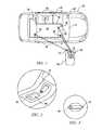
- FIG. 3is an exemplary illustration of a door handle of the vehicle shown in FIG. 1 ;
- FIG. 4is an exemplary illustration of a wallet card that is in selective communication with the vehicle as shown in FIG. 1 ;
- FIG. 5is an exemplary illustration of a process flow diagram illustrating a method of entering the vehicle as shown in FIG. 1 .
- modulerefers to an application specific integrated circuit (ASIC), an electronic circuit, a processor (shared, dedicated, or group) and memory that executes one or more software or firmware programs, a combinational logic circuit, and/or other suitable components that provide the described functionality.
- ASICapplication specific integrated circuit
- processorshared, dedicated, or group
- memorythat executes one or more software or firmware programs, a combinational logic circuit, and/or other suitable components that provide the described functionality.
- an exemplary embodimentis directed to a system 10 for activating a vehicle 18 to a key-on state by detecting the proximity of a mobile electronic device 20 .
- the system 10includes a control module 22 , a door control module 24 , a vehicle bus 26 , a first near field communication (“NFC”) antenna 30 , a second NFC antenna 32 , a short-range wireless antenna 36 , and a vehicle activation or start button 40 .
- the control module 22is a passive entry passive start (“PEPS”) module.
- the start button 40may be a push-button or twistable keyless start device configured to receive input from a user (e.g., a user pushes the start button 40 ) to activate the vehicle 18 to a key-on or ignition on state.
- a usere.g., a user pushes the start button 40
- the key-on stateelectrical power is supplied to an engine (not illustrated).
- the key-off stateelectrical power is not supplied to the engine (not illustrated).
- the door control module 24monitors a latching system 42 of multiple vehicle doors 44 to lock and unlock one or more vehicle doors 44 .
- the system 10may also include a docking station 46 (shown in FIG. 2 ) that is configured to receive the mobile electronic device 20 .
- the docking station 46may be a cradle configured to hold the mobile electronic device 20 .
- the docking station 46may be located within a center console 50 of the vehicle 18 , however, it is to be understood that other locations within an interior cabin 52 of the vehicle 18 may be used as well.
- the docking station 46may also be co-located with an inductive charging device (not illustrated) as well.
- the mobile electronic device 20may be any type of portable electronic device associated with or having a recognizable code such as, for example, a cellular telephone or a smartphone device.
- the recognizable codemay be the device address (e.g., a Bluetooth® device address) of the mobile electronic device 20 .
- the mobile electronic device 20includes an NFC tag 60 and a short-range wireless antenna 54 .
- the short-range wireless antenna 54is sized to send and receive RF signals that comply with a short-range wireless communications protocol for exchanging data over relatively short distances such as, for example, the Bluetooth® protocol conforming to IEEE Standard 802.15.
- the short-range wireless antenna 54is in communication with a control module 64 of the mobile electronic device 20 , where the control module 64 includes transceiver circuitry for communication with the short-range wireless antenna 54 .
- the control module 64includes transceiver circuitry for communication with the short-range wireless antenna 54 .
- a separate transceivermay be provided as well.
- the mobile electronic device 20is a dual-mode device.
- the control module 64includes logic, circuitry, or other interfaces needed to support a low-power version of the short-range wireless communications protocol in addition to the short-range wireless communications protocol.
- the low-power version of the short-range wireless communications protocolgenerally has a power consumption of about 15 mA or less.
- One example of the low-power version of the short-range wireless communications protocolis the Bluetooth Smart® low energy (“BLE”) protocol.
- the NFC tag 60is a passive device (e.g., having no power source). Instead, the NFC tag 60 may be placed within a predetermined distance (e.g., usually about 2-4 centimeters) from the either the first NFC antenna 30 or the second NFC antenna 32 of the vehicle 18 to induce an electrical current in an integrated circuit (not shown) within the NFC tag 60 (e.g., to inductively couple the NFC tag 60 to one of the first NFC antenna 30 or the second NFC antenna 32 ). The electrical current is used to power the integrated circuit of the NFC tag 60 , and broadcast a signal back to either the first NFC antenna 30 or the second NFC antenna 32 .
- a predetermined distancee.g., usually about 2-4 centimeters
- the mobile electronic device 20may not include a dedicated NFC tag 60 , and instead a user applies an NFC decal or sticker (not illustrated) to an exterior surface 66 of the mobile electronic device 20 .
- the NFC stickerincludes the circuitry generally included in the NFC tag 60 .
- the first NFC antenna 30 and the second NFC antenna 32may be embedded within various components of the vehicle 18 .
- the first NFC antenna 30may be embedded within a component located on an exterior surface of the vehicle 18 .
- the first NFC antenna 30may be located along an exterior door handle 70 of the vehicle 18 (shown in FIG. 3 ).
- the first NFC antenna 30may be placed within the interior cabin 52 , in a location 68 along a front dash 71 adjacent to a vehicle identification number (VIN) plate (not shown).
- VINvehicle identification number
- the second NFC antenna 32is embedded within a component located in an interior cabin 52 of the vehicle 18 .
- the second NFC antenna 32may be embedded within the docking station 46 that holds the mobile electronic device 20 .
- the second NFC antenna 32may be embedded within various other interior components as well such as, for example, a center console located under an arm rest (not shown).
- the first NFC antenna 30 and the second NFC antenna 32are both in communication with the control module 22 , where the control module 22 includes transceiver circuitry for communication with both the first NFC antenna 30 and the second NFC antenna 32 .
- a separate transceiver(not shown) may be provided as well.
- the short-range wireless antenna 36 of the vehicle 18is sized to send and receive RF signals that comply with a short-range wireless communications protocol such as, for example, the Bluetooth® protocol.
- the short-range wireless antenna 36is in communication with the control module 22 , where the control module 22 includes transceiver circuitry for communication with the short-range wireless antenna 36 . Alternatively, a separate transceiver (not shown) may be provided as well.
- the control module 22also includes dual-mode functionality. Thus, the control module 22 includes logic, circuitry, or other interfaces needed to support both the low-power version of the short-range wireless communications protocol (e.g., BLE) in addition and the short-range wireless communications protocol (e.g., Bluetooth®).
- the mobile device 20will eventually be placed within an area of proximity to the vehicle 18 (which may be a distance ranging up to about 100 meters around the vehicle 18 ).
- the control module 22periodically polls the area of proximity through the short-range wireless antenna 36 .
- the mobile electronic device 20attempts to establish connection with the control module 22 (or any other control module that has the capability to poll using the short-range wireless antenna 36 ) using the low-power version of the short-range wireless protocol (e.g., BLE).
- the recognizable code associated with the mobile electronic device 20is sent over the short-range wireless connection, and to the control module 22 .
- Memory associated with the control module 22may store the recognizable code of at least one mobile electronic device that has previously established short-range wireless communication (e.g., the vehicle 18 and the mobile electronic device 20 have been paired together in the past).
- the control module 22determines if any recognizable codes stored in the control module 22 memory matches the recognizable code of the specific mobile electronic device 20 attempting to establish communication with the control module 22 . If the control module 22 determines that the mobile device 20 has been paired in the past, the control module 22 may then authenticate the mobile electronic device 20 . The mobile electronic device 20 and the control module 22 are now connected to one another using the low-power version of the short-range wireless protocol.
- the control module 22may also send one or more control signals to the vehicle bus 26 .
- the control signalsawaken the vehicle bus 26 .
- the control signalsare then sent to the door control module 24 , which instructs the latching system 42 to unlock the vehicle doors 44 .
- the usermay set his or her mobile electronic device 20 within the docking station 46 (shown in FIG. 2 ), or any other interior component where the second NFC antenna 32 is embedded.
- the NFC tag 60is placed within the predetermined distance from the second NFC antenna 32 , thereby inducing an electrical current within the integrated circuit (not shown) of the NFC tag 60 .
- the NFC tag 60broadcasts a signal back to the second NFC antenna 32 .
- the second NFC antenna 32is in communication with the control module 22 .
- the control module 22Upon receipt of the signal from the second NFC antenna 32 , the control module 22 monitors the start button 40 for a user input (e.g., a user pushes the start button 40 ) that actives the vehicle 18 to the key-on or an ignition on state. Once the start button 40 receives the user input, the control module 22 may send a signal to activate the vehicle 18 to the key-on or ignition on state (e.g., the control module 22 may send a signal to a body control module to activate the vehicle 18 ). Thus, a user may activate the vehicle 18 to the key-on state without the need for a key or a fob device.
- a user inpute.g., a user pushes the start button 40
- the control module 22may send a signal to activate the vehicle 18 to the key-on or ignition on state (e.g., the control module 22 may send a signal to a body control module to activate the vehicle 18 ).
- a usermay activate the vehicle 18 to the key-on state without the
- the NFC tag 60In the event a battery (not shown) of the mobile electronic device 20 is substantially drained (i.e., the battery is dead and the mobile electronic device 20 is unpowered), access to the vehicle 18 may be established by the NFC tag 60 . That is, a user may unlock the doors 44 of the vehicle 18 using the NFC tag 60 . This is possible because the NFC tag 60 is a passive device, and does not need an external power source (e.g., the battery of the mobile electronic device 20 ). For example, a user may place the NFC tag 60 within the predetermined distance from the first NFC antenna 30 (e.g., located in the exterior door handle 70 shown in FIG. 3 ).
- An electrical currentis induced within an integrated circuit (not shown) of the NFC tag 60 , and the NFC tag 60 broadcasts a signal back to the first NFC antenna 30 .
- the signal broadcast from the NFC tag 60 back to the first antenna 30indicates the recognizable code (e.g., the Bluetooth® device address) associated with the mobile device 20 .
- the control module 22determines if the mobile device 20 has been paired in the past. If the mobile electronic device 20 has previously been paired with the control module 22 , then the control module 22 may send one or more control signals to the vehicle bus 26 . The control signals awaken the vehicle bus 26 . The control signals are also sent to the door control module 24 , which instructs the latching system 42 to unlock the vehicle doors 44 . The user may then enter the interior cabin 52 of the vehicle 18 , set his or her mobile electronic device 20 within the docking station 46 , and pushes the start button 40 to activate the vehicle 18 to the key-on or an ignition on state.
- the system 10may also include a valet or wallet card 80 (shown in FIG. 4 ).
- the wallet card 80may be used to obtain access to the vehicle 18 by a third party (e.g., a valet).
- a third partye.g., a valet
- the wallet card 80includes an NFC tag 82 and a break-away key 84 that may be selectively removed from the wallet card 80 (i.e., a user may twist off the break-away key 84 at a base portion 86 ).
- the control module 22determines if the special code indicated by the wallet card 80 indicates that access to the vehicle 18 should be granted (e.g., the VIN indicated by the wallet card 80 matches the VIN associated with the vehicle 18 ).
- control module 22determines access should be granted, then one or more control signals are sent to the vehicle bus 26 .
- the control signalsare also sent to the door control module 24 , which instructs the latching system 42 to unlock the vehicle doors 44 .
- the wallet card 80is then placed within the docking station 46 , and a user may activate the vehicle 18 to the key-on state by pressing the start button 40 .
- the wallet card 80may also be used to enter the vehicle 18 in the event a vehicle battery (not shown in FIG. 1 ) is drained, and the user does not have a set of vehicle keys (not shown) readily available. For example, if the vehicle battery is drained, a user may twist off the break-away key 84 from the wallet card 80 , and use the break-away key 84 to manually unlock the vehicle doors 44 . A user may then charge the vehicle battery, and activate the vehicle 18 by placing the wallet card 80 within the docking station 46 and pressing the start button 40 .
- the NFC tag 82may not be recognized by the second NFC antenna 32 . This may be due to RF interference.
- the RF interferencemay be caused by various electronic devices being placed in the vicinity of the docking station 46 , as users tend to place their electronic devices in the center console 50 (shown in FIG. 2 ).
- a usermay be able to follow a specific procedure to activate the vehicle 18 . The specific procedure is illustrated in FIG. 5 .
- method 100may begin at step 102 , where a user may place the wallet card 80 (or mobile device 20 ) within the docking station 46 (shown in FIG.). However, due to RF interference, the NFC tag 82 (or the NFC tag 60 of the mobile electronic device 20 ) is not recognized by the second NFC antenna 32 , and the user is unable to activate the vehicle 18 . Method 100 may then proceed to step 104 .
- step 104the user opens one or more doors 44 of the vehicle 18 , and places the wallet card 80 (or mobile device 20 ) within proximity of the first NFC antenna 30 (e.g., the exterior door handle 70 shown in FIG. 3 ).
- An electrical currentis induced within the NFC tag 82 (or the NFC tag 60 of the mobile electronic device 20 ) to broadcast the signal back to the first NFC antenna 30 .
- the signalincludes the special code associated with the wallet card 80 (or the device address associated with the mobile device 20 ).
- Method 100may then proceed to step 106 .
- step 106the door module 24 determines if one or more doors 44 of the vehicle 18 remain open (i.e., did a user close the door 44 after placing the wallet card 80 in front of the door handle 70 ). If one or more doors are still open, method 100 may then proceed to step 108 .
- step 108a signal may be sent over the vehicle bus 26 from the door module 24 to the control module 22 .
- the control module 22sets a latency timer. The latency timer allocates enough time for a user to re-enter the vehicle 18 , set the wallet card 80 or module electronic device 20 in the docking station 46 , and push the start button 40 (e.g., the latency timer may be set between about 30 to about 90 seconds. Method 100 may then terminate.
- step 110the vehicle doors 44 remain unlocked (e.g., the user did not lock the doors 44 when last exiting the vehicle). Method 100 may then proceed to step 112 .
- step 112a user may then set the wallet card 80 or mobile electronic device 20 in the docking station 46 , and push the start button 40 .
- the vehicle 18is activated to the key-on state. Method 100 may then terminate.
Landscapes
- Engineering & Computer Science (AREA)
- Mechanical Engineering (AREA)
- Computer Networks & Wireless Communication (AREA)
- Physics & Mathematics (AREA)
- General Physics & Mathematics (AREA)
- Lock And Its Accessories (AREA)
Abstract
Description
Claims (15)
Priority Applications (3)
| Application Number | Priority Date | Filing Date | Title |
|---|---|---|---|
| US13/590,434US8798809B2 (en) | 2012-08-21 | 2012-08-21 | System for passive entry and passive start using near field communication |
| DE102013216099.2ADE102013216099B4 (en) | 2012-08-21 | 2013-08-14 | SYSTEM FOR ACTIVATING A VEHICLE INTO A KEY IN STATE |
| CN201310366784.5ACN103625425B (en) | 2012-08-21 | 2013-08-21 | Utilize the keyless entry and the system of keyless activation of near-field communication |
Applications Claiming Priority (1)
| Application Number | Priority Date | Filing Date | Title |
|---|---|---|---|
| US13/590,434US8798809B2 (en) | 2012-08-21 | 2012-08-21 | System for passive entry and passive start using near field communication |
Publications (2)
| Publication Number | Publication Date |
|---|---|
| US20140058586A1 US20140058586A1 (en) | 2014-02-27 |
| US8798809B2true US8798809B2 (en) | 2014-08-05 |
Family
ID=50069759
Family Applications (1)
| Application Number | Title | Priority Date | Filing Date |
|---|---|---|---|
| US13/590,434ActiveUS8798809B2 (en) | 2012-08-21 | 2012-08-21 | System for passive entry and passive start using near field communication |
Country Status (3)
| Country | Link |
|---|---|
| US (1) | US8798809B2 (en) |
| CN (1) | CN103625425B (en) |
| DE (1) | DE102013216099B4 (en) |
Cited By (18)
| Publication number | Priority date | Publication date | Assignee | Title |
|---|---|---|---|---|
| CN105644448A (en)* | 2015-12-28 | 2016-06-08 | 奇瑞汽车股份有限公司 | Control method, device and system for rearview mirror of vehicle |
| US20160185318A1 (en)* | 2014-12-30 | 2016-06-30 | Fih (Hong Kong) Limited | Automobile and anti-theft method for the automobile |
| US9544853B1 (en) | 2016-03-21 | 2017-01-10 | GM Global Technology Operations LLC | Method and system for selectively activating a vehicle near field communication module |
| US20170282858A1 (en)* | 2014-09-11 | 2017-10-05 | Continental Automotive Gmbh | Keyless Entry Systems |
| US10164687B2 (en) | 2016-10-27 | 2018-12-25 | Samsung Electronics Co., Ltd. | NFC tag recognition device and NFC tag recognition system including the same |
| US10351099B2 (en) | 2014-04-30 | 2019-07-16 | Dura Operating, Llc | Vehicular keyless entry system |
| US10377376B2 (en) | 2016-10-06 | 2019-08-13 | Ford Global Technologies, Llc | Vehicle with environmental context analysis |
| US10407023B2 (en) | 2017-01-30 | 2019-09-10 | Ford Global Technologies, Llc | Remote starting of engines via vehicle keypads |
| US10475267B2 (en) | 2017-10-24 | 2019-11-12 | Ford Global Technologies, Llc | Vehicle finder card with a thin film battery |
| US10493954B2 (en)* | 2018-04-13 | 2019-12-03 | Volvo Car Corporation | Arrangement for unlocking a vehicle, method and a vehicle |
| US20200148168A1 (en)* | 2018-11-09 | 2020-05-14 | Ford Global Technologies, Llc | System and method for distributing digital vehicle keys to passive nfc devices via nfc |
| US10654447B2 (en)* | 2017-09-28 | 2020-05-19 | General Motors Llc | Vehicle sharing accessory module and system |
| US11027699B2 (en) | 2019-09-13 | 2021-06-08 | Ford Global Technologies, Llc | Backup key with wireless capabilities |
| US11072310B1 (en) | 2020-04-15 | 2021-07-27 | GM Global Technology Operations LLC | Method and system to mitigate smart phone battery drainage while using a virtual key to access a vehicle |
| US11267439B2 (en)* | 2019-03-08 | 2022-03-08 | Ford Global Technologies, Llc | Activation of valet mode for vehicles |
| US11312329B2 (en) | 2020-08-31 | 2022-04-26 | Toyota Motor North America, Inc. | Key fob communication control |
| US11428799B2 (en)* | 2018-10-12 | 2022-08-30 | Denso International America, Inc. | Up-sampling and cross-correlation for time of arrival determinations in passive entry/passive start systems |
| US11566443B2 (en) | 2019-09-13 | 2023-01-31 | Ford Global Technologies, Llc | Folding backup key |
Families Citing this family (68)
| Publication number | Priority date | Publication date | Assignee | Title |
|---|---|---|---|---|
| US10194017B2 (en)* | 2011-12-12 | 2019-01-29 | Mill Mountain Capital, LLC | Systems, devices and methods for vehicles |
| US9283931B2 (en)* | 2011-12-12 | 2016-03-15 | Mill Mountain Capital, LLC | Systems, devices and methods for vehicles |
| JP2013214909A (en)* | 2012-04-03 | 2013-10-17 | Denso Corp | Vehicle mobile equipment |
| US9162648B1 (en) | 2012-04-09 | 2015-10-20 | Google Inc. | Computing device as a vehicle key |
| US20140210592A1 (en)* | 2013-01-25 | 2014-07-31 | Ford Global Technologies, Llc | Apparatus and method for interfacing a wireless communication device to a communication device keypad in a vehicle |
| US9241235B2 (en)* | 2013-03-14 | 2016-01-19 | Voxx International Corporation | Passive entry cell phone and method and system therefor |
| FR3006485B1 (en)* | 2013-06-03 | 2015-05-22 | Renault Sa | DEVICE FOR SECURING ACCESS TO A VEHICLE USING A PORTABLE TELEPHONE |
| DE102013112679A1 (en)* | 2013-11-18 | 2015-05-21 | Dr. Ing. H.C. F. Porsche Aktiengesellschaft | Method for controlling at least one function of a motor vehicle |
| DE102014005699A1 (en)* | 2014-04-09 | 2015-10-15 | Audi Ag | Vehicle, system for activating and / or personalizing a vehicle system and method for detecting the presence of a mobile device |
| CN104980274A (en)* | 2014-04-09 | 2015-10-14 | 海拉胡克双合有限公司 | Smart phone, vehicle control system with the smart phone and control method |
| CN105278397B (en)* | 2014-07-24 | 2017-11-14 | 上海海拉电子有限公司 | A kind of vehicle remote control apparatus and control method |
| CN104464040B (en)* | 2014-07-28 | 2017-05-03 | 福建爱特点信息科技有限公司 | Car keyless entry system based on smart phone |
| US20160063786A1 (en)* | 2014-08-26 | 2016-03-03 | Hyundai America Technical Center, Inc. | Smartphone enabled passive entry go system |
| DE102014013238A1 (en) | 2014-09-05 | 2016-03-10 | Audi Ag | Method for operating a motor vehicle and a motor vehicle |
| DE102014112849A1 (en)* | 2014-09-05 | 2016-03-10 | Huf Hülsbeck & Fürst Gmbh & Co. Kg | Method for remote control of at least a first function of a safety device of a vehicle |
| JP2016056598A (en)* | 2014-09-10 | 2016-04-21 | パナソニックIpマネジメント株式会社 | Portable device and vehicle communication system |
| DE102014018057B4 (en)* | 2014-12-05 | 2019-03-14 | Audi Ag | Method for operating a motor vehicle |
| CN104648321B (en)* | 2015-01-28 | 2017-02-22 | 常州大学 | Method for optimizing automotive electronics application by utilizing NFC (Near Field Communication) |
| US20160292560A1 (en)* | 2015-04-02 | 2016-10-06 | Mitsumi Electric Co., Ltd. | Antenna apparatus and wireless communication system |
| US10101433B2 (en)* | 2015-05-01 | 2018-10-16 | GM Global Technology Operations LLC | Methods for locating a vehicle key fob |
| DE102015215240A1 (en)* | 2015-08-10 | 2017-02-16 | Volkswagen Aktiengesellschaft | Device for coupling a mobile communication device with a motor vehicle |
| FR3041167B1 (en)* | 2015-09-11 | 2019-05-31 | Valeo Comfort And Driving Assistance | ELECTRONIC CONTROL UNIT FOR A MOTOR VEHICLE AND METHOD FOR CONTROLLING THE FUNCTIONS OF THE MOTOR VEHICLE USING A MOBILE TERMINAL |
| US9643619B2 (en)* | 2015-09-21 | 2017-05-09 | Honda Motor Co., Ltd. | System and method for applying vehicle settings in a vehicle |
| US20170092026A1 (en)* | 2015-09-25 | 2017-03-30 | Faraday&Future Inc. | Low-power access authentication |
| DE102015014634B3 (en)* | 2015-11-12 | 2017-03-23 | Audi Ag | vehicle door |
| US10284653B2 (en)* | 2015-11-13 | 2019-05-07 | Ford Global Technolgies, Llc | Method and apparatus for utilizing NFC to establish a secure connection |
| CN105599703B (en)* | 2016-01-14 | 2017-10-24 | 北京汽车股份有限公司 | Automobile key detection method and device |
| US10902690B2 (en)* | 2016-02-26 | 2021-01-26 | Huf Hülsbeck & Fürst Gmbh & Co. Kg | Method for activating of at least one security function of a security system of a vehicle |
| US10300886B2 (en)* | 2016-03-15 | 2019-05-28 | GM Global Technology Operations LLC | Keyless control system |
| FR3050301B1 (en)* | 2016-04-19 | 2018-03-30 | Dura Operating, Llc | METHOD AND SYSTEM FOR SECURE ACCESS TO A VEHICLE |
| US9949303B2 (en)* | 2016-05-02 | 2018-04-17 | GM Global Technology Operations LLC | Short range wireless communication system for a vehicle |
| FR3051578B1 (en)* | 2016-05-19 | 2018-05-25 | Continental Automotive France | NEAR FIELD COMMUNICATION DEVICE HAVING TWO NFC ZONES |
| DE102016217318A1 (en) | 2016-07-26 | 2018-02-01 | Volkswagen Aktiengesellschaft | Method, computer program and device for checking authorization of a mobile communication device |
| DE102016215022B4 (en)* | 2016-08-11 | 2020-03-05 | Audi Ag | Method for operating an access system for a motor vehicle and access system for a motor vehicle |
| DE102016217498B4 (en)* | 2016-09-14 | 2019-03-07 | Volkswagen Aktiengesellschaft | Space-neutral coupling antenna |
| DE102016218874A1 (en)* | 2016-09-29 | 2018-03-29 | Takata AG | Vehicle components, switches for placement on a vehicle component, and methods of manufacturing a vehicle component |
| KR101883934B1 (en)* | 2016-10-14 | 2018-08-01 | 콘티넨탈 오토모티브 시스템 주식회사 | Card type smart key for vehicles ana method thereof |
| US10051435B2 (en)* | 2016-12-12 | 2018-08-14 | Denso International America, Inc. | Mobile device location system |
| DE102016225540B4 (en)* | 2016-12-20 | 2023-06-15 | Audi Ag | Motor vehicle with removable central control unit and motor vehicle fleet and control unit |
| US10322696B2 (en)* | 2017-01-18 | 2019-06-18 | Gm Global Technology Operations Llc. | Vehicle environment imaging systems and methods |
| DE102017201308B4 (en) | 2017-01-27 | 2020-07-02 | Continental Automotive Gmbh | Method for verifying a predetermined maximum spatial distance of a radio key with respect to a motor vehicle and control device, motor vehicle and radio key |
| DE102017105255A1 (en)* | 2017-03-13 | 2018-09-13 | Huf Hülsbeck & Fürst Gmbh & Co. Kg | Safety system for activating at least one safety function in a vehicle |
| CN107292210B (en)* | 2017-05-23 | 2023-01-06 | 意昂神州(北京)科技有限公司 | Shielding cabinet for detecting radio frequency function of PEPS controller and detection method |
| DE102017111475A1 (en)* | 2017-05-24 | 2018-11-29 | Bundesdruckerei Gmbh | Access control device for controlling access to an access area |
| US10131321B1 (en)* | 2017-07-18 | 2018-11-20 | Ford Global Technologies, Llc | System for keyless valet parking |
| US10266149B1 (en)* | 2017-12-01 | 2019-04-23 | Ford Global Technologies, Llc | Vehicle unlocking systems, devices, and methods |
| US10370005B2 (en)* | 2017-12-05 | 2019-08-06 | Ford Global Technologies, Llc | Method and apparatus for vehicle valet control devices |
| DE102017221991B3 (en)* | 2017-12-06 | 2019-03-21 | Continental Automotive Gmbh | A communication method for a plurality of vehicle transceivers and a radio key transceiver, and a communication system for a vehicle |
| FR3075728B1 (en)* | 2017-12-21 | 2019-11-22 | Psa Automobiles Sa | METHOD FOR ASSEMBLING A VEHICLE |
| DE102018002028B4 (en) | 2018-03-14 | 2020-03-26 | Daimler Ag | Driving authorization system |
| US11097689B2 (en)* | 2018-03-27 | 2021-08-24 | Denso International America, Inc. | Passive entry and passive start system and method using temporary keys |
| CN108661432A (en)* | 2018-05-07 | 2018-10-16 | 芜湖博创新能源科技有限公司 | A kind of car door that new-energy automobile uses and respective doors car key |
| US10317517B1 (en) | 2018-05-15 | 2019-06-11 | Delphi Technologies, Llc | Vehicle location device |
| CN109696869B (en)* | 2018-05-25 | 2023-06-30 | 广西科技大学 | Automobile central door lock control device and control method based on NFC near field communication technology |
| DE102018125218A1 (en)* | 2018-10-11 | 2020-04-16 | Huf Hülsbeck & Fürst Gmbh & Co. Kg | System for a passive vehicle access system |
| DE102019108255A1 (en)* | 2019-03-29 | 2020-10-01 | Huf Hülsbeck & Fürst Gmbh & Co. Kg | Method for controlling a mobile identification transmitter |
| US11598838B2 (en) | 2019-06-26 | 2023-03-07 | Aptiv Technologies Limited | Detection device |
| US11014534B2 (en) | 2019-07-13 | 2021-05-25 | Toyota Motor North America, Inc. | Remote access of transports |
| US11386722B2 (en) | 2019-07-13 | 2022-07-12 | Toyota Motor North America, Inc. | Remote access of transports |
| CN110503758A (en)* | 2019-08-23 | 2019-11-26 | 上海元城汽车技术有限公司 | Control method, device, electronic equipment and the computer-readable medium of vehicle |
| CN112622820B (en)* | 2019-09-24 | 2022-09-09 | 比亚迪股份有限公司 | Vehicle owner identity recognition system and method and vehicle |
| CN112886994B (en)* | 2019-11-29 | 2022-05-06 | 北京小米移动软件有限公司 | Terminal |
| EP3849092A1 (en)* | 2020-01-09 | 2021-07-14 | Rohde & Schwarz GmbH & Co. KG | Radio communication system and method for operating a mobile radio in a vehicle communication arrangement |
| DE102020006073B4 (en) | 2020-10-05 | 2024-07-18 | Mercedes-Benz Group AG | Method for checking the presence of a digital vehicle key in a vehicle and vehicle with a system suitable for this purpose |
| DE102020127438A1 (en)* | 2020-10-19 | 2022-04-21 | Huf Hülsbeck & Fürst Gmbh & Co. Kg | System for detecting an activation action in an activation area for a vehicle |
| CN112572349A (en)* | 2020-12-22 | 2021-03-30 | 广州橙行智动汽车科技有限公司 | Vehicle digital key processing method and system |
| CN116798147A (en)* | 2022-03-18 | 2023-09-22 | 法雷奥舒适驾驶助手公司 | NFC control system, control method and motor vehicle for motor vehicle |
| WO2024077367A1 (en)* | 2022-10-10 | 2024-04-18 | SILVA DE ALMEIDA, Erminio | Device for remote management of functions by proximity |
Citations (9)
| Publication number | Priority date | Publication date | Assignee | Title |
|---|---|---|---|---|
| USRE32914E (en)* | 1984-06-12 | 1989-05-02 | Creditcard Keys Company | Key and retainer card combination |
| US20080164988A1 (en) | 2007-01-08 | 2008-07-10 | Snap-On Incorporated | Apparatus and method to transfer data from a tire pressure monitor tool to a remote output device such as a printer |
| US7629875B2 (en)* | 2005-03-18 | 2009-12-08 | Continental Automotive Systems Us, Inc. | Method to report LF remote signal strength via a RF link to an electronic control unit |
| US20100102943A1 (en)* | 2008-10-29 | 2010-04-29 | Dei Holdings, Inc. | Wireless Touch Sensor |
| US7725129B2 (en) | 2007-05-16 | 2010-05-25 | Oliver David Grunhold | Cell phone based vehicle control system |
| US20100198428A1 (en)* | 2009-01-30 | 2010-08-05 | Delphi Technologies, Inc. | Multi-purpose fob system |
| US20100222939A1 (en) | 2009-02-27 | 2010-09-02 | Toyota Motor Engineering & Manufacturing North America, Inc. | Methods and Systems for Remotely Managing A Vehicle |
| US20100305779A1 (en)* | 2007-06-19 | 2010-12-02 | Hassan Hasib | Remote vehicle control system utilizing multiple antennas |
| US7990255B2 (en)* | 2006-11-02 | 2011-08-02 | Audiovox Corporation | Range extending positive repeater |
Family Cites Families (5)
| Publication number | Priority date | Publication date | Assignee | Title |
|---|---|---|---|---|
| USD405679S (en)* | 1997-10-31 | 1999-02-16 | Almblad Robert E | Key handle applique set |
| JP4391546B2 (en)* | 2007-04-06 | 2009-12-24 | 三菱電機株式会社 | Vehicle communication system |
| US8847731B2 (en) | 2007-10-10 | 2014-09-30 | Samsung Electronics Co., Ltd. | System and method for communicating with a vehicle |
| US11042816B2 (en) | 2009-10-30 | 2021-06-22 | Getaround, Inc. | Vehicle access control services and platform |
| DE102011011697B4 (en) | 2011-02-18 | 2021-01-21 | Daimler Ag | Locking system and method for controlling an access authorization or driving authorization for a vehicle |
- 2012
- 2012-08-21USUS13/590,434patent/US8798809B2/enactiveActive
- 2013
- 2013-08-14DEDE102013216099.2Apatent/DE102013216099B4/enactiveActive
- 2013-08-21CNCN201310366784.5Apatent/CN103625425B/enactiveActive
Patent Citations (10)
| Publication number | Priority date | Publication date | Assignee | Title |
|---|---|---|---|---|
| USRE32914E (en)* | 1984-06-12 | 1989-05-02 | Creditcard Keys Company | Key and retainer card combination |
| US7629875B2 (en)* | 2005-03-18 | 2009-12-08 | Continental Automotive Systems Us, Inc. | Method to report LF remote signal strength via a RF link to an electronic control unit |
| US7990255B2 (en)* | 2006-11-02 | 2011-08-02 | Audiovox Corporation | Range extending positive repeater |
| US20080164988A1 (en) | 2007-01-08 | 2008-07-10 | Snap-On Incorporated | Apparatus and method to transfer data from a tire pressure monitor tool to a remote output device such as a printer |
| US7589619B2 (en) | 2007-01-08 | 2009-09-15 | Snap-On Incorporated | Apparatus and method to transfer data from a tire pressure monitor tool to a remote output device such as a printer |
| US7725129B2 (en) | 2007-05-16 | 2010-05-25 | Oliver David Grunhold | Cell phone based vehicle control system |
| US20100305779A1 (en)* | 2007-06-19 | 2010-12-02 | Hassan Hasib | Remote vehicle control system utilizing multiple antennas |
| US20100102943A1 (en)* | 2008-10-29 | 2010-04-29 | Dei Holdings, Inc. | Wireless Touch Sensor |
| US20100198428A1 (en)* | 2009-01-30 | 2010-08-05 | Delphi Technologies, Inc. | Multi-purpose fob system |
| US20100222939A1 (en) | 2009-02-27 | 2010-09-02 | Toyota Motor Engineering & Manufacturing North America, Inc. | Methods and Systems for Remotely Managing A Vehicle |
Non-Patent Citations (1)
| Title |
|---|
| Related U.S. Appl. No. 13/299,786, filed Nov. 18, 2011. |
Cited By (22)
| Publication number | Priority date | Publication date | Assignee | Title |
|---|---|---|---|---|
| US10351099B2 (en) | 2014-04-30 | 2019-07-16 | Dura Operating, Llc | Vehicular keyless entry system |
| US20170282858A1 (en)* | 2014-09-11 | 2017-10-05 | Continental Automotive Gmbh | Keyless Entry Systems |
| US20160185318A1 (en)* | 2014-12-30 | 2016-06-30 | Fih (Hong Kong) Limited | Automobile and anti-theft method for the automobile |
| US9694788B2 (en)* | 2014-12-30 | 2017-07-04 | Fih (Hong Kong) Limited | Automobile and anti-theft method for the automobile |
| CN105644448A (en)* | 2015-12-28 | 2016-06-08 | 奇瑞汽车股份有限公司 | Control method, device and system for rearview mirror of vehicle |
| US9544853B1 (en) | 2016-03-21 | 2017-01-10 | GM Global Technology Operations LLC | Method and system for selectively activating a vehicle near field communication module |
| US10377376B2 (en) | 2016-10-06 | 2019-08-13 | Ford Global Technologies, Llc | Vehicle with environmental context analysis |
| US10164687B2 (en) | 2016-10-27 | 2018-12-25 | Samsung Electronics Co., Ltd. | NFC tag recognition device and NFC tag recognition system including the same |
| US10407023B2 (en) | 2017-01-30 | 2019-09-10 | Ford Global Technologies, Llc | Remote starting of engines via vehicle keypads |
| US10654447B2 (en)* | 2017-09-28 | 2020-05-19 | General Motors Llc | Vehicle sharing accessory module and system |
| US10475267B2 (en) | 2017-10-24 | 2019-11-12 | Ford Global Technologies, Llc | Vehicle finder card with a thin film battery |
| US10493954B2 (en)* | 2018-04-13 | 2019-12-03 | Volvo Car Corporation | Arrangement for unlocking a vehicle, method and a vehicle |
| US11428799B2 (en)* | 2018-10-12 | 2022-08-30 | Denso International America, Inc. | Up-sampling and cross-correlation for time of arrival determinations in passive entry/passive start systems |
| US11714184B2 (en) | 2018-10-12 | 2023-08-01 | Denso International America, Inc. | Up-sampling and cross-correlation for time of arrival determinations in passive entry/passive start systems |
| US12270894B2 (en) | 2018-10-12 | 2025-04-08 | Denso International America, Inc. | Up-sampling and cross-correlation for time of arrival determinations in passive entry/passive start systems |
| US20200148168A1 (en)* | 2018-11-09 | 2020-05-14 | Ford Global Technologies, Llc | System and method for distributing digital vehicle keys to passive nfc devices via nfc |
| US11034330B2 (en)* | 2018-11-09 | 2021-06-15 | Ford Global Technologies, Llc | System and method for distributing digital vehicle keys to passive NFC devices via NFC |
| US11267439B2 (en)* | 2019-03-08 | 2022-03-08 | Ford Global Technologies, Llc | Activation of valet mode for vehicles |
| US11027699B2 (en) | 2019-09-13 | 2021-06-08 | Ford Global Technologies, Llc | Backup key with wireless capabilities |
| US11566443B2 (en) | 2019-09-13 | 2023-01-31 | Ford Global Technologies, Llc | Folding backup key |
| US11072310B1 (en) | 2020-04-15 | 2021-07-27 | GM Global Technology Operations LLC | Method and system to mitigate smart phone battery drainage while using a virtual key to access a vehicle |
| US11312329B2 (en) | 2020-08-31 | 2022-04-26 | Toyota Motor North America, Inc. | Key fob communication control |
Also Published As
| Publication number | Publication date |
|---|---|
| CN103625425B (en) | 2017-08-15 |
| CN103625425A (en) | 2014-03-12 |
| DE102013216099A1 (en) | 2014-02-27 |
| DE102013216099B4 (en) | 2019-09-05 |
| US20140058586A1 (en) | 2014-02-27 |
Similar Documents
| Publication | Publication Date | Title |
|---|---|---|
| US8798809B2 (en) | System for passive entry and passive start using near field communication | |
| CN109204229B (en) | Vehicle sharing system | |
| US10475267B2 (en) | Vehicle finder card with a thin film battery | |
| US11643050B2 (en) | Transportation vehicle, electronic vehicle radio key and system for passive access to a transportation vehicle and methods therefor | |
| US9110772B2 (en) | Mobile device-activated vehicle functions | |
| US9845070B2 (en) | Method for triggering a command in a motor vehicle by means of a data exchange between a control device and an identifier element | |
| US9536365B2 (en) | System and method for keyless entry and remote starting vehicle with an OEM remote embedded in vehicle | |
| US9858735B2 (en) | User proximity detection for activating vehicle convenience functions | |
| WO2019004310A1 (en) | Car sharing system and car sharing program | |
| US20140210592A1 (en) | Apparatus and method for interfacing a wireless communication device to a communication device keypad in a vehicle | |
| US10091633B2 (en) | Passive entry passive start systems employing consumer mobile devices as portable remote control units | |
| WO2015174012A1 (en) | Electronic key system | |
| JP5952143B2 (en) | Notification device | |
| US20160225211A1 (en) | Authentication of a user provided with a mobile device by a vehicle | |
| JP2013002111A (en) | Electronic key system | |
| JP2015059398A (en) | Vehicle controller | |
| CN110546046A (en) | Button accessory device for controlling access to a vehicle | |
| JP2014175855A (en) | On-vehicle system, vehicle control device, communication control method, and vehicle control method | |
| JP2019055656A (en) | Car sharing system | |
| JP7091990B2 (en) | Vehicle control systems and methods | |
| JP5365845B2 (en) | Vehicle door control system and vehicle door control method | |
| US11951945B1 (en) | NFC-based enclosure access using passive energy harvesting | |
| JP2011097534A (en) | Automatic cradle-mode changing device | |
| JP2016006599A (en) | Portable terminal | |
| JP2010265640A (en) | Power transfer-type electronic key system, method for supplying electric power to electronic key, and the electronic key |
Legal Events
| Date | Code | Title | Description |
|---|---|---|---|
| AS | Assignment | Owner name:GM GLOBAL TECHNOLOGY OPERATIONS LLC, MICHIGAN Free format text:ASSIGNMENT OF ASSIGNORS INTEREST;ASSIGNORS:KALHOUS, AMANDA J.;WEIGERT, NORMAN J.;REEL/FRAME:028819/0275 Effective date:20120817 | |
| AS | Assignment | Owner name:WILMINGTON TRUST COMPANY, DELAWARE Free format text:SECURITY AGREEMENT;ASSIGNOR:GM GLOBAL TECHNOLOGY OPERATIONS LLC;REEL/FRAME:030694/0500 Effective date:20101027 | |
| FEPP | Fee payment procedure | Free format text:PAYOR NUMBER ASSIGNED (ORIGINAL EVENT CODE: ASPN); ENTITY STATUS OF PATENT OWNER: LARGE ENTITY | |
| STCF | Information on status: patent grant | Free format text:PATENTED CASE | |
| AS | Assignment | Owner name:GM GLOBAL TECHNOLOGY OPERATIONS LLC, MICHIGAN Free format text:RELEASE BY SECURED PARTY;ASSIGNOR:WILMINGTON TRUST COMPANY;REEL/FRAME:034287/0415 Effective date:20141017 | |
| MAFP | Maintenance fee payment | Free format text:PAYMENT OF MAINTENANCE FEE, 4TH YEAR, LARGE ENTITY (ORIGINAL EVENT CODE: M1551) Year of fee payment:4 | |
| MAFP | Maintenance fee payment | Free format text:PAYMENT OF MAINTENANCE FEE, 8TH YEAR, LARGE ENTITY (ORIGINAL EVENT CODE: M1552); ENTITY STATUS OF PATENT OWNER: LARGE ENTITY Year of fee payment:8 |