US8798788B2 - System and method for dispensing prescriptions - Google Patents
System and method for dispensing prescriptionsDownload PDFInfo
- Publication number
- US8798788B2 US8798788B2US13/346,969US201213346969AUS8798788B2US 8798788 B2US8798788 B2US 8798788B2US 201213346969 AUS201213346969 AUS 201213346969AUS 8798788 B2US8798788 B2US 8798788B2
- Authority
- US
- United States
- Prior art keywords
- dispensing
- container
- station
- carrier
- frame
- Prior art date
- Legal status (The legal status is an assumption and is not a legal conclusion. Google has not performed a legal analysis and makes no representation as to the accuracy of the status listed.)
- Expired - Lifetime, expires
Links
Images


Classifications
- G—PHYSICS
- G07—CHECKING-DEVICES
- G07F—COIN-FREED OR LIKE APPARATUS
- G07F17/00—Coin-freed apparatus for hiring articles; Coin-freed facilities or services
- G07F17/0092—Coin-freed apparatus for hiring articles; Coin-freed facilities or services for assembling and dispensing of pharmaceutical articles
- G—PHYSICS
- G07—CHECKING-DEVICES
- G07F—COIN-FREED OR LIKE APPARATUS
- G07F11/00—Coin-freed apparatus for dispensing, or the like, discrete articles
- G07F11/02—Coin-freed apparatus for dispensing, or the like, discrete articles from non-movable magazines
- G07F11/44—Coin-freed apparatus for dispensing, or the like, discrete articles from non-movable magazines in which magazines the articles are stored in bulk
- G—PHYSICS
- G07—CHECKING-DEVICES
- G07F—COIN-FREED OR LIKE APPARATUS
- G07F11/00—Coin-freed apparatus for dispensing, or the like, discrete articles
- G07F11/62—Coin-freed apparatus for dispensing, or the like, discrete articles in which the articles are stored in compartments in fixed receptacles
- Y—GENERAL TAGGING OF NEW TECHNOLOGICAL DEVELOPMENTS; GENERAL TAGGING OF CROSS-SECTIONAL TECHNOLOGIES SPANNING OVER SEVERAL SECTIONS OF THE IPC; TECHNICAL SUBJECTS COVERED BY FORMER USPC CROSS-REFERENCE ART COLLECTIONS [XRACs] AND DIGESTS
- Y10—TECHNICAL SUBJECTS COVERED BY FORMER USPC
- Y10T—TECHNICAL SUBJECTS COVERED BY FORMER US CLASSIFICATION
- Y10T29/00—Metal working
- Y10T29/53—Means to assemble or disassemble
- Y10T29/53687—Means to assemble or disassemble by rotation of work part
Definitions
- the present inventionis directed generally to the dispensing of prescriptions of pharmaceuticals, and more specifically is directed to the automated dispensing of pharmaceuticals.
- the present inventionis directed to an automated system and method for dispensing pharmaceuticals, particularly tablets and capsules, and other small discrete objects.
- Embodiments of the system and methodare capable of receiving a patient's prescription information, selecting a container, labeling the container, dispensing the tablets or capsules into the labeled container, applying a closure to the filled, labeled container, and offloading the container to a designated location.
- the tabletsare dispensed with high speed dispensing bins that employ forced air to agitate and singulate the tablets.
- the other functions within the systemare typically carried out at stations designed to offer speed, flexibility and precision to the dispensing operation.
- embodiments of the inventionare directed to a method of dispensing solid pharmaceutical items of substantially identical size and configuration from a bulk of such solid pharmaceutical items stored in a housing.
- the methodcomprises the steps of: providing a singulating bin comprising a hopper and a dispensing channel fluidly connected thereto, the dispensing channel defining a flow path; applying a forwardly-directed jet into the dispensing channel; passing a series of solid pharmaceutical items in single file from the hopper into the dispensing channel; accelerating the solid pharmaceutical items in the dispensing channel with the forwardly-directed jet; counting the number of solid pharmaceutical items that pass a predetermined point in the dispensing channel; comparing the number of solid pharmaceutical items that have passed the predetermined point with a predetermined number; and applying a rearwardly-directed jet into the dispensing channel after a predetermined number of solid pharmaceutical items have passed the predetermined point to draw any additional items in the dispensing channel back into the hopper.
- This methodcan dispense pharmaceutical items rapidly and accurately.
- embodiments of the present inventionare directed to an apparatus for dispensing solid pharmaceutical items, comprising: a frame; a container dispensing station attached to the frame; a labeling station attached to the frame; a labeling carrier configured to grasp and transport a container from the container dispensing station to the labeling station; a dispensing station having a plurality of bins that receive and dispense solid pharmaceutical items; a dispensing carrier that receives a labeled container from the labeling carrier and transports the labeled container to the dispensing station for filling with solid pharmaceutical items from one of the bins; and a controller operatively connected with and controlling the operation of the container dispensing station, the labeling station, the labeling carrier, the dispensing station, and the dispensing carrier.
- Such an apparatuscan dispense filled, labeled pharmaceuticals rapidly and accurately.
- embodiments of the present inventionare directed to an apparatus for dispensing solid pharmaceutical items, comprising a dispensing station comprising a plurality of bins for storing the items, each of the bins containing items of substantially identical size and configuration, and at least some of the bins containing items that differ in size and/or composition from the items contained in others of the housings.
- Each of the binsincludes a dispensing outlet on one side that dispenses items, a replenishment opening on a side thereof opposite the dispensing outlet, and an electronic unit that monitors the counting of items traveling through the dispensing outlet.
- the binsare mounted on a frame such that the dispensing outlets face an access region within the frame and the replenishment openings face away from the frame.
- a dispensing carrieris configured to transport containers to be filled with the items.
- the dispensing carrieris positioned within the access region.
- a controllercontrols the operation of the dispensing carrier. In this configuration, bins can be replenished without removing them from the frame or interfering with the operation of the apparatus as it dispenses from other bins.
- FIG. 1is a flow chart illustrating an embodiment of a method according to the present invention.
- FIG. 2is a perspective view of a pharmaceutical tablet dispensing system according to the present invention.
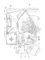
- FIG. 3is a cutaway view of the system of FIG. 2 illustrating the container dispensing station, the labeling carrier, the dispensing carrier, and the closure dispensing station.
- FIG. 4is a top view of the container dispensing station of the system of FIG. 2 showing the cup holding a container in the donating position.
- FIG. 5is a top view of the container dispensing station of FIG. 4 showing the cup holding a container in the receiving position.
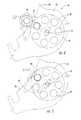
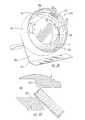
- FIG. 6is an enlarged perspective view of the container dispensing station of FIG. 4 .
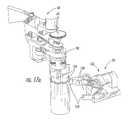
- FIG. 7is a perspective view of the gripping unit of the label carrier of the system of FIG. 2 with the fingers thereof rotated to a radially inward position and the unit itself in a raised position above the container-dispensing cup.
- FIG. 7Ais a section view of the gripping unit of FIG. 7 .
- FIG. 8is a perspective view of the gripping unit of FIG. 7 with the fingers thereof in the process of rotating radially outwardly and the unit itself in a lowered position into a container in the container dispensing cup.
- FIG. 9is a perspective view of the gripping unit of FIG. 7 with the fingers thereof rotated to a radially outward position and the unit itself rising with the container above the container dispensing cup.
- FIG. 10is a bottom view of the gripping unit of FIG. 7 with the fingers thereof in rotated to a radially inward position.
- FIG. 11is a bottom view of the gripping unit of FIG. 7 with the fingers thereof rotated to an intermediate position.
- FIG. 12is a bottom view of the gripping unit of FIG. 7 with the fingers thereof in rotated to a radially outward position.
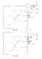
- FIG. 13is a schematic top view of the labeling station of the system of FIG. 2 prior to the application of a label on a container.
- FIGS. 14-16are schematic top views of the labeling station of FIG. 13 during the application of a label on a container as the container is held and rotated by the gripping unit of FIG. 7 .
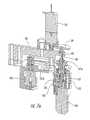
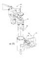
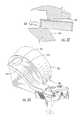
- FIG. 17is an enlarged perspective view of the transfer of a container from the labeling carrier of FIG. 7 to the dispensing carrier of the system of FIG. 2 .
- FIG. 18is an enlarged perspective view of the lower carriage and the grip unit of the dispensing carrier of FIG. 17 illustrating that the lower carriage can be moved vertically and horizontally and that the grip unit can be rotated about two axes.
- FIG. 19is an enlarged perspective view of a dispensing bin employed in the system of FIG. 2 .
- FIGS. 20A and 20Bare section views of the dispensing bin of FIG. 19 showing how the size of the dispensing channel of the dispensing bin can be adjusted.
- FIG. 21is a greatly enlarged side view of the dispending bin of FIG. 19 showing how the height of the dispensing channel can be adjusted.
- FIG. 22is a bottom view of the dispensing bin of FIG. 19 showing how the width of the dispensing channel can be adjusted.
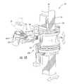
- FIG. 23is an enlarged exploded view of the dispensing bin of FIG. 19 showing its interconnection with the low pressure manifold, the high pressure conduit, and the electronics mounted on the frame of FIG. 3 .
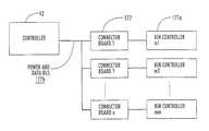
- FIG. 23Ais a schematic diagram of the controller and three exemplary connector boards from the frame and three exemplary bin-controlling circuit boards.
- FIG. 23Bis a schematic diagram of another embodiment of the controller of the system of FIG. 2 .
- FIG. 24is an enlarged assembled view of the dispensing bin of FIG. 19 with the low pressure manifold, the high pressure conduit, and the electronics mounted on the frame.
- FIG. 25is an enlarged side view of the securing member of the dispensing bin of FIG. 19 showing how the securing member locks the dispensing bin in place on the frame.
- FIG. 26is an enlarged section view of the assembled dispensing bin and frame of FIG. 24 with tablets loaded into the bin.
- FIG. 27is an enlarged section view of the assembled dispensing bin and frame of FIG. 24 with tablets being agitated by low pressure air flowing upwardly through the bin.
- FIG. 28is an enlarged section view of the assembled dispensing bin and frame of FIG. 24 with high pressure air being applied to the dispensing channel, such that tablets are drawn therein in single file in a lengthwise orientation.
- FIG. 29is an enlarged section view of the assembled dispensing bin and frame of FIG. 24 with a desired number of tablets dispensed into the container.
- FIG. 30is an enlarged perspective view of the closure dispenser of the closure dispensing station of the system of FIG. 2 .
- FIG. 31is an enlarged perspective view of the closure dispenser of FIG. 30 with the closure bin removed.
- FIG. 32is a greatly enlarged section view of a closure unable to be oriented with the closure dispenser of FIG. 30 .
- FIG. 33is a greatly enlarged section view of a closure able to be oriented with the closure dispenser of FIG. 30 .
- FIG. 34is a bottom perspective view of the closure dispenser of FIG. 30 .
- FIG. 35is an enlarged side perspective view of the closure holder of the system of FIG. 2 with a filled container in a lower position.
- FIG. 36is an enlarged side perspective view of the closure holder of FIG. 35 with the container raised to engage a closure.
- FIG. 37is an enlarged side perspective view of the closure holder of FIG. 35 with the filled, closed container lowered.
- the inventionrelates to a system and process for dispensing pharmaceuticals.
- the processis described generally with reference to FIG. 1 .
- the processbegins with the identification of the proper container, tablets or capsules and closure to be dispensed based on a patient's prescription information (Box 20 ).
- a container of the proper sizeis dispensed at a container dispensing station (Box 22 ), then grasped and moved to a labeling station (Box 24 ).
- the labeling stationapplies a label (Box 26 ), after which the container is transferred to a transport system and moved to a tablet dispensing station (Box 28 ), from which the designated tablets are dispensed in the designated amount into the container (Box 30 ).
- the filled containeris then grasped again and moved to a closure dispensing station (Box 32 ), where a closure of the proper size has been dispensed (Box 34 ).
- the filled containeris secured with a closure (Box 36 ), then transported to an offload station and offloaded (Box 38 ).
- FIGS. 2-37A system that can carry out this process is illustrated in FIGS. 2-37 and designated broadly therein at 40 .
- the system 40includes a support frame 44 for the mounting of its various components.
- the illustrated support frame 40includes a base 46 that rests on an underlying surface.
- Four uprights 48extend vertically from the base 46 and define an internal cavity 45 within which the operable components of the system 40 generally reside.
- a pair of top rails 50are attached to the upper ends of the uprights 48 , and two cross-members 52 span the distance between the front and rear ends of the top rails 50 .
- Top, intermediate and bottom arches 54 , 55 , 56are mounted to extend from the front surfaces of the front uprights 48 .
- the frame 44also includes two lower rails 51 that extend between pairs of uprights 48 well below the top rails 52 , and further includes a pair of intermediate rails 53 that are mounted in vertical alignment between two uprights 48 below one of the top rails 52 .
- the frame 40 illustrated hereinis exemplary and can take many configurations that would be suitable for use with the present invention.
- the frame 40provides a strong, rigid foundation to which other components can be attached at desired locations, and other frame forms able to serve this purpose may also be acceptable for use with this invention.
- the system 40generally includes as operative stations a controller 42 , a container dispensing station 58 , a labeling station 60 , a tablet dispensing station 62 , a closure dispensing station 64 , and an offloading station 66 .
- Containers, tablets and closuresare moved between these stations with two different conveying devices: a labeling carrier 68 and a dispensing carrier 70 .
- Each of the operative stations and the conveying devicesis described in detail below.
- the controller 42which is mounted to and below the top arch 54 , controls the operation of remainder of the system 40 .
- the controller 42will be operatively connected with an external device, such as a personal or mainframe computer, that provides input information regarding prescriptions.
- the controller 42may be a stand-alone computer that directly receives manual input from a pharmacist or other operator.
- An exemplary controlleris a conventional microprocessor-based personal computer.
- the container dispensing station 58which is mounted to the bottom arch 56 , comprises a plurality of tubes 80 oriented generally vertically and about a common axis of rotation.
- a plurality of tubes 80oriented generally vertically and about a common axis of rotation.
- three sets of tubes 80 of different sizesare illustrated; the ensuing discussion is equally applicable to each.
- a bottom plate 82is fixed to the bottom ends of the tubes 80 and a top plate 84 fixed to the top ends of the tubes 80 .
- Each of the bottom and top plates 82 , 84have apertures that correspond to the ends of the tubes 80 .
- the tubes 80 and bottom and top plates 82 , 84are free to rotate as a unit about the axis of rotation Al and are driven by a motor or other rotary drive unit attached to the bottom plate 82 (the motor is not shown).
- a sorting plate 86 or other memberis fixed to the lower arch 56 below and parallel to the bottom plate 82 .
- the sorting plate 86includes a slotted opening 87 at one edge. As is shown in FIGS.
- a cup 88 or other receiving memberis pivotally attached to lower surface of the sorting plate 86 such that it may move between a receiving position below the opening 87 ( FIG. 5 ) and a donating position beyond the perimeter of the sorting plate 86 ( FIG. 4 ) (pivoting of the cup 88 is controlled by the controller 42 through a second motor (not shown)).
- each set of tubes 80Prior to operation, the tubes 80 within each set are filled with containers of similar size, with each set of tubes 80 housing containers of different sizes. Filling can be carried out by loading the containers in a preferred orientation through an orientation tube 84 a (see FIG. 2 ), which has an opening 85 a with a downward extending finger 86 a that ensure that the containers are loaded with their open ends facing upwardly. The containers travel through the orientation tube 84 through the openings in the top plate 84 in an upright orientation with their open ends facing upwardly, so that they are vertically stacked within the tubes 80 .
- each set of tubes 80is filled with different sizes of containers, while in other embodiments, individual tubes 80 within the same set of tubes may be filled with different sizes of containers.
- the controller 42signals the container dispensing station 58 that a container of a specified size is desired.
- the bottom and top plates 82 , 84rotate until a tube 80 that houses a container is positioned above the opening 87 .
- the cup 88is in its receiving position beneath the opening 87 ( FIG. 5 ).
- the lowermost containerdrops downwardly through the opening 87 and into the cup 88 .
- the controller 42then signals the cup 88 to pivot to its donating position ( FIGS. 4 and 6 ), wherein the container can be grasped by the labeling carrier 68 .
- the cup 88includes a support finger 89 trailing the receptacle portion of the cup 88 to support containers remaining in the tubes 80 when the cup 88 is in the donating position.
- the containersmay be presented for grasping in a horizontal disposition, or the dispensing apparatus may include a conveyor unit that presents the containers one at a time for grasping.
- the dispensing apparatusmay include a conveyor unit that presents the containers one at a time for grasping.
- the labeling carrier 68comprises an upright support member 91 fixed to the base of the frame 40 , a carriage 92 attached to and moveable vertically on the support member 91 , a swing arm 94 attached thereto that pivots about a vertical axis A 2 , and a gripping unit 96 attached to the free end of the swing arm 94 . Both the vertical movement of the carriage 92 and the pivoting of the swing arm 94 and gripping unit 96 can be induced with conventional robotic techniques that need not be described in detail herein.
- the gripping unit 96has a body portion 98 , a base 102 rotatably attached to the body portion 98 for rotation about an axis A 3 , a clutch mechanism 101 attached to the body portion 98 and coupled to the base 102 , a plurality of fingers 104 (three are illustrated herein) that are rotatable and eccentrically mounted to the base 102 and extend downwardly therefrom generally parallel to each other, and a motor 100 attached to the body portion 98 and coupled to the fingers 104 .
- Each finger 104is fixed to a finger shaft 105 , which in turn is fixed to a planet gear 106 such that, as the planet gear 106 rotates, so must the attached finger 104 .
- Each planet gear 106is attached to the base 102 in such a way as to be able to rotate freely relative thereto.
- a sun gear 107is rotatably mounted onto the base 102 and can freely rotate in relation thereto about the axis A 3 .
- Each planet gear 106engages the sun gear 107 , so that when the sun gear 107 rotates in relation to the base 102 , the planet gears 106 also rotate relative to the base 102 about a respective axis A 4 , A 5 , A 6 .
- a motor shaft 108is fixed to the sun gear 107 along the axis A 3 and is coupled to the motor 100 via a motor gear train 109 .
- Each finger 104has an arcuate outer surface 104 a that defines a portion of a circle, such that, when all of the fingers 104 are rotated to a radially inward position ( FIGS. 7 and 10 ), the outer surfaces 104 a of the fingers 104 form a stepped vertical cylinder, with their vertices 104 b adjacent to one another.
- the fingers 104can be rotated about their eccentric axes of rotation A 4 , A 5 , A 6 ( FIG. 11 ) so that their vertices 104 b move radially outwardly from each other; rotation in this manner expands the circle defined by the radially outwardmost portions of the outer surfaces 104 a of the fingers 104 (see FIGS. 8 , 9 and 12 ).
- the controller 42signals the labeling carrier 68 to grasp the container.
- the carriage 92slides on the support member 91 , thereby moving the swing arm 94 to a height such that the lower ends of the fingers 104 are above the upper edge of the container.
- the swing arm 94pivots relative to the carriage 92 such that the fingers 104 are positioned directly over the container.
- the fingers 104are rotated radially inwardly ( FIGS. 7 and 10 ) to a retracted position.
- the carriage 92then descends, which action lowers the fingers 104 into the cavity of the container.
- the motor 100then exerts a torque on the sun gear 107 via the motor gear train 109 and the motor shaft 108 , thereby causing the sun gear 107 to exert a torque on the planet gears 106 and a torque on the base 102 (via the planet gears 106 and finger shafts 105 ). Because the clutch 101 restrains the base 102 from rotating (via a pulley 101 a and a belt 101 b ), the planet gears 106 rotate about axes A 4 , A 5 , A 6 in response to this torque, causing the fingers 104 to turn and expand radially outward (see FIGS. 8 and 11 ) until they contact the inside surface of the container (see FIGS. 9 and 12 ).
- the container wallresists further expansion of the fingers 104 , thereby inducing an opposing torque on the base 102 transmitted via the fingers 104 , finger shafts 105 , and planet gears 106 .
- the base 102 and container—now held by the fingers 104rotates about the axis A 3 .
- the clutch 101continues to exert a restraining torque on the base 102 as the base 102 rotates.
- the fingers 104continue to exert pressure on the inside of the container (as explained above) as the base 102 rotates, thereby inducing the container to rotate and enabling the fingers 104 to lift the container from the cup 88 .
- the controller 42signals the carriage 92 to rise on the support member 91 . As this occurs, the fingers 104 lift and carry the container from the cup 88 , and the container continues to rotate relative to the body portion 98 due to the rotation of the base 102 .
- the gripping fingersmay take a different configuration (e.g., they may not form a cylinder when rotated inwardly).
- gripping fingersmay be used that grip the outer surface of the container.
- suctionmay be employed to temporarily grasp and move the container.
- the labeling station 60includes a printer 110 that is controlled by the controller 42 .
- the printer 110which is mounted to one side of the base 46 , prints and presents an adhesive label that is to be affixed to the container.
- the labeling station 60also includes a wiping device, such as the brush 112 illustrated in FIG. 8 , that is positioned adjacent to the exit port 114 of the printer 110 .
- the containeris moved (under the direction of the controller 42 ) to the exit port 114 of the printer 110 through appropriate translation of the carriage 92 on the support member 91 and pivoting of the swing arm 94 relative to the carriage 92 ( FIG. 13 ).
- the labeling carrier 68presents the rotating container to the label ( FIG. 13 ); the rotation of the container enables the wiping device to smoothly apply the label to the container (augmented by the brush 112 —see FIGS. 14-16 ).
- the containermay be transferred to pinch rollers located at the exit port 114 .
- the dispensing carrier 70includes an upper carriage 120 that slides upon a rail 122 extending between the cross-members 52 , a rail 124 that extends downwardly from the carriage 120 , a lower carriage 126 that slides vertically along the rail 124 , and a grip unit 128 that is mounted on the lower carriage 126 via horizontally disposed circular tracks 130 that revolve around the lower carriage 126 .
- the grip unit 128includes a traveler unit 132 that is mounted to the tracks 130 , an axle 134 that is rotatably mounted in and extends from the traveler unit 132 , and a gripping mechanism 136 that is attached to and is rotatable with the axle 134 .
- the gripping mechanism 136has two jaws 138 that can confront each other and exert clamping force on an object (such as a container of the type discussed herein).
- the jaws 138have a curved portion 139 that assists in gripping the cylindrical container.
- the jaws 138may be configured such that they compress the container only to a desired torque level (e.g. with a clutch mechanism, or with a sensor that detects a predetermined current level for the drive motor) in order to prevent crushing of the container, or such that they compress only to predetermined positions selected to match the sizes of the different containers used with the system 40 .
- the dispensing carrier 70has the capability of moving the gripping mechanism 136 (and, in turn, an object grasped therein) to designated locations within the cavity 45 of the frame 44 . Movement from end to end within the cavity 45 (i.e., toward and away from the arches 54 , 55 , 56 ) is accomplished by inducing movement of the upper carriage 120 on the rail 122 . Vertical movement is accomplished by inducing movement of the lower carriage 126 on the rail 124 . The grip unit 128 may also revolve around the rail 124 about an axis A 7 through revolution of the tracks 130 around the carriage 126 . The gripping mechanism 136 may rotate relative to the traveler unit 132 about an axis A 8 defined by the axle 134 . Induction and control of these movements may be achieved through conventional robotic techniques that need not be described in detail herein. The skilled artisan will also appreciate that other components for grasping and maneuvering a container may also be employed with the present invention.
- transfer of the labeled container from the labeling carrier 68 to the dispensing carrier 70is achieved by the controller 42 directing the dispensing carrier 70 to move the gripping mechanism 136 to a position in which the jaws 138 can clamp onto the outer surface of the container as it is presented by the labeling carrier 68 .
- the position for transferis proximate to the printer 110 and the tablet dispensing station 62 .
- the controller 42first signals the dispensing carrier 70 to close the jaws 138 onto the outer surface of the container, then directs the labeling carrier 68 to retract the fingers 104 to their radially inward positions so that the container is held only by the jaws 138 .
- the fingers 104are then withdrawn from the container (through either upward movement of the fingers 104 by the labeling carrier 68 or downward movement of the labeled container by the dispensing container 70 ), and the labeled container is ready to be filled with tablets.
- the tablet dispensing station 62comprises a plurality of tablet dispensing bins 150 , each of which holds a bulk supply of individual tablets (typically the bins 150 will hold different tablets).
- the dispensing bins 150which are typically substantially identical in size and configuration, are organized in an array mounted on the intermediate rails 53 of the frame 44 , and each has a dispensing channel 154 with an outlet that faces generally in the same direction, to create an access region for the dispensing carrier 70 .
- the identity of the tablets in each binsis known by the controller 42 , which can direct the dispensing carrier 70 to transport the container to the proper bin 150 .
- the bins 150may be labeled with a bar code or other indicia to allow the dispensing carrier 70 to confirm that it has arrived at the proper bin 150 .
- the dispensing bins 150are configured to cingulate, count, and dispense the tablets contained therein, with the operation of the bins 150 and the counting of the tablets being controlled by the controller 42 .
- Some embodimentsmay employ the controller 42 as the device which monitors the locations and contents of the bins 150 ; others may employ the controller 42 to monitor the locations of the bins, with the bins 150 including indicia (such as a bar code or electronic transmitter) to identify the contents to the controller 42 ; in still other embodiments the bins 150 may generate and provide location and content information to the controller 42 , with the result that the bins 150 may be moved to different positions on the frame 42 without the need for manual modification of the controller 42 (i.e., the bins 150 will update the controller 42 automatically).
- any of a number of dispensing units that singulate and count discrete objectsmay be employed; however, dispensing units that rely upon targeted air flow and a singulating nozzle assembly, such as the devices described in co-pending U.S. patent application Ser. No. 09/934,940, filed Aug. 22, 2001 and entitled DEVICE TO COUNT AND DISPENSE ARTICLES and in U.S. Provisional Application No. 60/306,782, filed Jul. 20, 2001 for DEVICE TO COUNT AND DISPENSE ARTICLES, are preferred (these applications are hereby incorporated herein by reference in their entireties). Bins of this variety may also include additional features, such as those described below.
- the bins 150can be described generally as having a tablet-filled hopper 153 through which air flows and agitates the tablets contained therein, and the aforementioned dispensing channel 154 through which the tablets are dispensed one at a time. Suction can be applied to the channel 154 through a forwardly-directed jet 155 ; a rearwardly-directed jet 156 is also included that can reverse the motion of tablets within the channel 154 .
- the jets 155 , 156are controlled by the controller 42 , which initiates forward air flow in response to a customer order and activates rearward air flow in response to the passage of a certain quantity of tablets through in the dispensing channel 154 (as detected by a counting sensor 154 a located in the dispensing channel 154 ).
- the jets 155 , 156may be controlled by a local controller unique to each bin 150 (as described in some detail below).
- the bins 150can filled or replenished with tablets via access from a pivoting door 180 located at the upper rear portion of the bin 150 .
- the location of the door 180 opposite the outlet of the dispensing channel 154enables an operator to replenish the bin 150 without disconnecting it from the frame 44 or interfering with the dispensing from this or another bin 150 .
- the pivoting of the lower end portion of the door 180 and the inclusion of side walls 180 acauses an open door 180 to form a funnel-like configuration, which configuration can facilitate pouring of pharmaceuticals into the bin 150 .
- the bins 150may include components that permit the entry to the dispensing channel 154 to be adjusted in size to complement the size and configuration of the tablet to be dispensed. This can be achieved through a stationary wall 160 , a moveable wall 161 , a moveable ceiling 162 and a moveable floor 163 that form the entry to (and in some instances the perimeter of) the dispensing channel 154 .
- the stationary wall 160is a portion 151 a of the housing 151 of the bin 150 .
- the stationary wall 160also forms a portion of a recess 301 that extends inwardly into the housing 151 .
- the ceiling 162is part of a ceiling unit 302 that fits within the recess 301 .
- the ceiling unit 302also includes a vertical panel 304 extends downwardly from a lateral edge of the ceiling 162 .
- the vertical panel 304includes two apertures and an engagement projection 306 that engages a slot in a wall of the recess 301 .
- an adjustment knob 320 and attached threaded shank 322insert through a threaded nut 324 attached to the vertical panel 304 ; the knob 320 is held in place within a recess in the housing 151 .
- the moveable wall 161is part of a moveable wall unit 308 that includes front and rear panels 310 , 312 that extend transversely from front and rear portions of the moveable wall 161 .
- Two posts 314extend from the moveable wall 161 and pass through the apertures of the vertical panel 304 of the ceiling unit 302 into elongated slots 316 of the housing.
- a front projection 318extends beyond the front panel 310 and is received in a slot 319 in the housing.
- the moveable floor 163is part of a floor unit 326 that also includes a front portion 328 with a slot 330 that receives the front projection 318 of the moveable wall 161 , gussets 331 , 332 , 333 that help to guide the moveable wall 161 , and an adjustment knob 334 and an attached threaded shank 336 that extend into and through an attached nut 338 .
- the adjustment knob 334is maintained in place within a slot 340 in the housing of the bin 150 , and the floor 163 is maintained in vertical position by two tines 342 .
- Two springs 344surround the posts 314 between the moveable wall 161 and the vertical panel 304 .
- the floor 163includes a series of apertures 349 located to the side of the dispensing channel 154 . These apertures 349 can provide additional flow to this region of the bin 150 . The additional flow can encourage tablets that tumble to a position adjacent the dispensing channel 154 during agitation to rejoin the remaining tablets; otherwise, they may remain in this “dead” area, which can tend to clog entry into the dispensing channel 154 .
- the adjustment knob 334is rotated about its axis. Rotation of the shank 336 within the nut 338 induces the floor 163 to slide horizontally between the housing 151 and the tines 342 . In doing so, the posts 314 are free to slide through the apertures in the vertical panel 304 ; the moveable wall 161 is maintained in contact with the floor 163 by compression from the springs 344 . In the illustrated embodiment, the exact position of the moveable wall 161 can be monitored with markings 346 located on the rear portion of the floor 163 .
- the adjustment knob 320is rotated. Interaction between the shank 322 and the nut 324 causes the ceiling unit 302 to slide within the recess 301 .
- the posts 314slide within the slots 316 in the housing 151 , and the moveable wall 161 is driven upwardly or downwardly by the ceiling 162 .
- the front projection 318 of the moveable wall 161remains in the slots 319 , 330 .
- the exact position of the ceiling 162can be monitored with markings 348 located on the side of the housing 151 .
- the configuration of the dispensing channel 154 described abovecan provide an essentially “gapless” channel for the tablets to travel in, which can improve performance of the system 40 .
- the floor 163 and the stationary wall 160 of the dispensing channel 154remain in place, which provides a constant location to which the container receiving tablets can be delivered.
- a further optional feature of the illustrated dispensing channel 154is a splash guard 158 ( FIG. 28 ), which is located at the outlet of the dispensing channel 154 .
- the splash guard 158can reduce or eliminate the risk that a tablet traveling to the container falls or bounces outside the container.
- the splash guard 158is formed of a spongy foam material (such as polyethylene foam); such a material enables the container to be compressed against the splash guard 158 , causing it to deform around the upper edge of the container and seal it so that tablets do not stray from the container.
- the presentation of the container to the dispensing channel 154 by the dispensing carrier 70can occur with a larger margin for error in positioning.
- FIGS. 3 and 23 - 25Another feature of the tablet dispensing station 62 that may be included with the present invention is illustrated in FIGS. 3 and 23 - 25 .
- a low pressure manifold 170 having a number of inlets 171is mounted to the frame 44 and extends horizontally; the manifold 170 , which is fluidly connected to a low pressure source such as a vacuum motor (not shown), provides low level (i.e., about 2 psi) suction to the bin 150 to either (a) maintain a door 172 in a closed position when the particular bin 150 is not in use or (b) agitate tablets within the bin when the door 172 is opened by a solenoid 173 or other actuating unit within the bin 150 .
- a low pressure manifold 170 having a number of inlets 171is mounted to the frame 44 and extends horizontally; the manifold 170 , which is fluidly connected to a low pressure source such as a vacuum motor (not shown), provides low level (i
- a high pressure (i.e., about 30 psi) conduit 175 with a fitting 176also extends horizontally from its mounting point on the frame 44 , with the fitting 176 projecting toward the bin 150 .
- the fitting 176may be a check valve, so that high pressure air is not expelled if the bin 150 is not present.
- the high pressure conduit 175is fluidly connected to a high pressure source (not shown).
- a connector circuit board 177is mounted horizontally below the manifold 170 ; the circuit board 177 or other electrical connector provides an electrical connection between the controller 42 and the bin-controlling circuit board 177 a (or other electronic component) of the bin 150 for power and data signals from the controller 42 , such as those that control the opening and closing of the door 172 , the application of suction and/or positive pressure through the conduit 175 , and the counting sensor 154 a . Thus, all three of these connections should be made for the bin 150 to operate.
- the frame 44 illustrated hereinincludes prongs 183 ( FIG. 23 ) that facilitate re-establishment of the aforementioned connections.
- the prongs 183are positioned below the manifold 170 and are configured for slidable movement with slots 184 on the housing 151 that receives the prongs 183 .
- the prongs 183include recesses 183 a that receive pins 187 located on a pivoting member 189 .
- the connector board 177is mounted to the frame 44 and supports electronic circuitry which contains a “location identifier” unique to the physical location of the connector board 177 on the frame 44 .
- the connector board 177provides its mating bin-controlling circuit board 177 a with regulated and unregulated power, a physical connection to the data bus 177 b , and the location identifier for the connector board 177 .
- the connector board 177communicates power and data to the bin-controlling circuit board 177 a via the bus 177 b (which is a power and data bus).
- the bin-controlling circuit board 177 acontains a “bin identifier” unique to that bin that can be read by the controller 42 .
- the bin-controlling circuit board 177 aprocesses counting and dispensing functions such as triggering the solenoid 173 , triggering the air valves 190 , and processing signals from the sensor 154 a .
- the bin-controlling circuit board 177 acan receive dispense instructions and communicate its unique identifier and other information relative to its counting function, such as count status, empty condition, and the like. In some embodiments the bin-controlling circuit board 177 a may also send or receive data such as inventory levels or sensor condition. Upon command from the controller 42 the bin controlling circuit board 177 a can initiate and control the dispense and count process.
- the controller 42can search for a unique bin identifier and associate it with a certain location identifier.
- the controller 42may then direct the dispensing carrier 70 to carry the container to the appropriate position for dispensing.
- accurate dispensing of the pharmaceuticalbecomes independent of a priori knowledge of the pharmaceutical's physical location on the frame 44 . This gives the user the ability to quickly re-arrange the bin locations according to changing requirements such as alphabetization or utilization ranking.
- each bin 150may contain an additional machine readable identifier 150 a which is more readily accessible to an operator wielding a reader 150 b which is connected to the controller 42 .
- the operatormay select and read the bin identifier 150 a to automatically associate various external data such as pharmaceutical identifiers, replenishment quantities, etc., to the bins' information set.
- This identifier 150 amay be placed on the inside of the replenishment door 180 so that the door 180 must be opened before the reader can access the identifier 150 a.
- the dispensing carrier 70moves the container to the exit port of the selected dispensing bin 150 .
- the controller 42signals the solenoid 173 to open the door 172 (more specifically, the solenoid 173 retracts, and a plunger 173 a moves toward the door 172 , striking a finger 172 a located on the top portion of the door 172 and causing it to pivot open—see FIG. 27 ).
- This opening of the door 172draws low pressure air up through the hopper 153 from a screen 153 a on the bottom of the hopper 153 , through another screen 153 b on the top portion of the hopper 153 , and to the opening 172 b, thereby agitating the tablets contained in the hopper 153 ( FIG. 27 ).
- the controller 42signals a valve 190 a connected with the forwardly-directed jets to open, which causes high pressure air to be drawn outwardly through the dispensing channel 154 ( FIG. 28 ). Tablets are oriented into a preferred orientation by the shape of the entry to the dispensing channel 154 and dispensed into the container through the dispensing channel 154 .
- the counting sensor 154 acounts the tablets as they pass through a predetermined point in the dispensing channel 154 .
- the controller 42activates the valve 190 b associated with the rearwardly-directed jet 56 and deactivates the dispensing bin 150 , the solenoid 173 deactivates, thereby closing the door 172 ( FIG. 29 ), and the dispensing carrier 70 moves the filled container to the closure dispensing station 64 .
- the closure dispensing station 64includes two closure dispensers 200 and two closure holders 202 , each of which is mounted to the intermediate arch 55 of the frame 44 between the container dispensing station 58 and the labeling station 60 .
- each closure dispenser 200 and closure holder 202contains and manipulates a single size of closure.
- the closure dispensers 200house a bulk supply of closures and dispense them, in a preferred orientation, one at a time to a respective closure holder 202 , where they are secured onto a filled container.
- One each of a closure dispenser 200 and a closure holder 202are described in detail below; those skilled in this art will appreciate that any number of closure dispensers and closure holders may be employed with the present invention.
- the closure dispenser 200( FIGS. 30-34 ) includes an open-ended bin 204 that feeds a rotatable hopper 206 .
- the hopper 206has an open top end to receive closures from the bin 204 and a circumferential groove 208 at its lower end that surrounds a central circular island 209 .
- the groove 208has a depth that is approximately the diameter of a closure and a width that is approximately the width of the closure.
- a circumferential protrusion 210juts radially inwardly from the wall 207 of the hopper 206 above the groove 208 and island 209 .
- the sizes and configurations of the groove 208 , island 209 and protrusion 210are such that a closure (which is a flat, open-ended cylinder) can enter the groove 208 from above only when the closure is oriented so that the open end of the closure faces the island 209 .
- a closurewhich is a flat, open-ended cylinder
- the open end of the closurecan receive a portion of the edge of the island 209 , thereby allowing the closure to be positioned slightly farther from the wall 207 (and, therefore, slide into the groove 208 ) than a closure oriented with the closed end facing the island 209 , which cannot pass between the island 209 and the protrusion 210 in this manner (compare FIGS. 32 and 33 ).
- the floor 211 of the hopper 206has an opening 213 through which one closure can pass.
- the floor 211abuts a plate 214 ( FIG. 34 ) that also includes at least one opening 212 that has a length in a direction substantially tangent to the groove 208 that is sufficient to pass one closure.
- the hopper 206is rotatably mounted on the plate 214 .
- a channel 218is positioned below the opening 212 and leads to the closure holder 202 ; the channel 218 is sized such that the closure substantially maintains the orientation it takes upon exiting the opening 212 .
- Closuresare dispensed by filling the bin with closures and rotating the hopper 206 relative to the plate 214 . As the hopper 206 rotates, each closure tumbles until it eventually reaches the desired orientation and slides into the groove 208 (tumbling of the closures is augmented by two agitating projections 209 a ). As the hopper 206 continues to rotate, the closure eventually reaches the opening 213 , at which point it passes through the opening 212 and falls into the channel 218 . The channel 218 conveys the closure in its desired orientation to the closure holder 202 .
- the closure holder 202includes a vertical mounting post 222 upon which are mounted a container receiving stage 224 and a closure holding stage 226 .
- the container receiving stage 226comprises a block 228 that is slidable relative to the mounting post 222 driven by a rack-and-pinion drive unit 227 .
- a platform 230extends generally horizontally away from the block 228 .
- Two open-ended cups 232 a , 232 b sized to receive filled containersare mounted on the upper surface of the platform 230 .
- a rotatable drive wheel 233 or other rotary drive unitis positioned between the cups 232 a , 232 b that rotates the cups 232 a , 232 b about their respective longitudinal axes; rotation of the drive wheel 233 is controlled by the controller 42 .
- the closure holding stage 226has a ceiling 234 and three downwardly-extending walls 236 that form two closure securing compartments 238 .
- a fork 239is mounted to the mounting post 222 and forms the rear wall of the securing compartments 238 ; the fork 239 includes openings that receive closures from the channels 218 .
- a pair of ledges 240 a , 240 bextend into each compartment 238 from the opposing surfaces of the walls 236 .
- the ledges 240 a , 240 bextend a sufficient distance from the walls 236 that a closure cannot pass downwardly between the ledges 240 a , 240 b , but a container can pass upwardly between them.
- the ledges 240 a , 240 b , walls 236 and ceiling 234are also configured so that a closure can pass forwardly (i.e., away from the fork 239 ) to allow a combined container and closure to pass out of the compartments 238 .
- the dispensing carrier 70grasps the filled container, conveys it to the closure dispensing station 64 , and places it in a selected cup 232 a , 232 b as directed by the controller 42 ( FIG. 35 ).
- the block 228slides upwardly relative to the mounting post 222 , thereby moving the platform 230 upwardly.
- the platform 230ascends, and the upper end of the container contacts and intercepts the closure positioned in the compartment 238 .
- the container and closurecontinue to rise until the container compresses the closure against the ceiling 234 ( FIG. 36 ).
- the selected cup 232 athen rotates, thereby rotating the container, as the ceiling 234 holds the closure in place, causing the container to rotate relative to the closure. This rotation secures the closure to the container.
- the platform 230then lowers; the closed container descends until the closure contacts the ledges 240 a , 240 b , with the closed container dangling therefrom ( FIG. 37 ).
- the dispensing carrier 70then moves to the closed container, grasps it, and moves it to the offloading station 66 .
- the offloading station 66includes a plurality of compartments 250 positioned between the intermediate and upper arches 55 , 54 . These can be organized in any manner desired by the operator; for example, they may be organized by customer name, time of dispensing, contents of the container, or any other scheme.
- the dispensing carrier 70conveys the closed container to the compartment directed by the controller 42 and releases it there. The dispensing carrier is then free to grasp another labeled container at the labeling station 60 and perform its operations again.
Landscapes
- Physics & Mathematics (AREA)
- General Physics & Mathematics (AREA)
- Medical Preparation Storing Or Oral Administration Devices (AREA)
Abstract
Description
Claims (7)
Priority Applications (1)
| Application Number | Priority Date | Filing Date | Title |
|---|---|---|---|
| US13/346,969US8798788B2 (en) | 2002-05-14 | 2012-01-10 | System and method for dispensing prescriptions |
Applications Claiming Priority (4)
| Application Number | Priority Date | Filing Date | Title |
|---|---|---|---|
| US38040202P | 2002-05-14 | 2002-05-14 | |
| US10/437,353US6971541B2 (en) | 2002-05-14 | 2003-05-13 | System and method for dispensing prescriptions |
| US11/018,596US8774962B2 (en) | 2002-05-14 | 2004-12-21 | System and method for dispensing prescriptions |
| US13/346,969US8798788B2 (en) | 2002-05-14 | 2012-01-10 | System and method for dispensing prescriptions |
Related Parent Applications (1)
| Application Number | Title | Priority Date | Filing Date |
|---|---|---|---|
| US11/018,596ContinuationUS8774962B2 (en) | 2002-05-14 | 2004-12-21 | System and method for dispensing prescriptions |
Publications (2)
| Publication Number | Publication Date |
|---|---|
| US20120104017A1 US20120104017A1 (en) | 2012-05-03 |
| US8798788B2true US8798788B2 (en) | 2014-08-05 |
Family
ID=29549964
Family Applications (11)
| Application Number | Title | Priority Date | Filing Date |
|---|---|---|---|
| US10/437,353Expired - LifetimeUS6971541B2 (en) | 2002-05-14 | 2003-05-13 | System and method for dispensing prescriptions |
| US11/019,048Expired - Fee RelatedUS7118006B2 (en) | 2002-05-14 | 2004-12-21 | System and method for dispensing prescriptions |
| US11/019,023Expired - LifetimeUS7988404B2 (en) | 2002-05-14 | 2004-12-21 | System and method for dispensing prescriptions |
| US11/018,792Expired - Fee RelatedUS6974049B2 (en) | 2002-05-14 | 2004-12-21 | System and method for dispensing prescriptions |
| US11/018,596Expired - LifetimeUS8774962B2 (en) | 2002-05-14 | 2004-12-21 | System and method for dispensing prescriptions |
| US11/018,496Expired - Fee RelatedUS6974050B2 (en) | 2002-05-14 | 2004-12-21 | System and method for dispensing prescriptions |
| US11/019,026Expired - Fee RelatedUS6971544B2 (en) | 2002-05-14 | 2004-12-21 | System and method for dispensing prescriptions |
| US11/018,793Expired - Fee RelatedUS7275353B2 (en) | 2002-05-14 | 2004-12-21 | System and method for dispensing prescriptions |
| US12/126,048Expired - Fee RelatedUS7565784B2 (en) | 2002-05-14 | 2008-05-23 | Apparatus for dispensing prescriptions |
| US12/126,162Expired - Fee RelatedUS7565782B2 (en) | 2002-05-14 | 2008-05-23 | System and method for dispensing prescriptions |
| US13/346,969Expired - LifetimeUS8798788B2 (en) | 2002-05-14 | 2012-01-10 | System and method for dispensing prescriptions |
Family Applications Before (10)
| Application Number | Title | Priority Date | Filing Date |
|---|---|---|---|
| US10/437,353Expired - LifetimeUS6971541B2 (en) | 2002-05-14 | 2003-05-13 | System and method for dispensing prescriptions |
| US11/019,048Expired - Fee RelatedUS7118006B2 (en) | 2002-05-14 | 2004-12-21 | System and method for dispensing prescriptions |
| US11/019,023Expired - LifetimeUS7988404B2 (en) | 2002-05-14 | 2004-12-21 | System and method for dispensing prescriptions |
| US11/018,792Expired - Fee RelatedUS6974049B2 (en) | 2002-05-14 | 2004-12-21 | System and method for dispensing prescriptions |
| US11/018,596Expired - LifetimeUS8774962B2 (en) | 2002-05-14 | 2004-12-21 | System and method for dispensing prescriptions |
| US11/018,496Expired - Fee RelatedUS6974050B2 (en) | 2002-05-14 | 2004-12-21 | System and method for dispensing prescriptions |
| US11/019,026Expired - Fee RelatedUS6971544B2 (en) | 2002-05-14 | 2004-12-21 | System and method for dispensing prescriptions |
| US11/018,793Expired - Fee RelatedUS7275353B2 (en) | 2002-05-14 | 2004-12-21 | System and method for dispensing prescriptions |
| US12/126,048Expired - Fee RelatedUS7565784B2 (en) | 2002-05-14 | 2008-05-23 | Apparatus for dispensing prescriptions |
| US12/126,162Expired - Fee RelatedUS7565782B2 (en) | 2002-05-14 | 2008-05-23 | System and method for dispensing prescriptions |
Country Status (2)
| Country | Link |
|---|---|
| US (11) | US6971541B2 (en) |
| CA (3) | CA2428556C (en) |
Cited By (1)
| Publication number | Priority date | Publication date | Assignee | Title |
|---|---|---|---|---|
| US11345544B2 (en) | 2019-03-29 | 2022-05-31 | Mckesson Corporation | Apparatuses, systems, and methods for the automated retrieval and dispensing of articles |
Families Citing this family (117)
| Publication number | Priority date | Publication date | Assignee | Title |
|---|---|---|---|---|
| US20020095343A1 (en)* | 2001-01-12 | 2002-07-18 | Barton Steven P. | Apparatus and method for providing point of purchase products |
| US20050167489A1 (en)* | 2001-01-12 | 2005-08-04 | Barton Steven P. | Point of purchase dispensing device with container and method of using same |
| US6971541B2 (en)* | 2002-05-14 | 2005-12-06 | Parata Systems, Inc. | System and method for dispensing prescriptions |
| US7624894B2 (en)* | 2002-05-31 | 2009-12-01 | William Olin Gerold | Automated pill-dispensing apparatus |
| US20040059463A1 (en)* | 2002-06-24 | 2004-03-25 | Scriptpro Llc | Active control center for use with an automatic dispensing system for prescriptions and the like |
| AU2003259259A1 (en)* | 2002-07-29 | 2004-02-16 | Mckesson Automation Systems, Inc. | Article dispensing and counting method and device |
| US7303094B2 (en)* | 2002-08-09 | 2007-12-04 | Kevin Hutchinson | Vacuum pill dispensing cassette and counting machine |
| US7228198B2 (en) | 2002-08-09 | 2007-06-05 | Mckesson Automation Systems, Inc. | Prescription filling apparatus implementing a pick and place method |
| KR100541064B1 (en)* | 2004-04-13 | 2006-01-10 | (주)제이브이엠 | Tablet discharge device for automatic pharmaceutical packing machine |
| US7080755B2 (en) | 2004-09-13 | 2006-07-25 | Michael Handfield | Smart tray for dispensing medicaments |
| JP2006100484A (en)* | 2004-09-29 | 2006-04-13 | Taiyo Yuden Co Ltd | Component supply apparatus |
| US8789700B2 (en)* | 2004-10-01 | 2014-07-29 | Edge Medical Properties, Llc | System and method for communicating and inspecting a multiple tablet order |
| US9710866B2 (en) | 2005-09-30 | 2017-07-18 | Edge Medical, Llc | System and method for processing a multiple prescription order |
| US8123036B2 (en) | 2004-10-01 | 2012-02-28 | Edge Medical Properties, Llc | Pill assembly for pill packaging and delivery systems |
| US7930064B2 (en)* | 2004-11-19 | 2011-04-19 | Parata Systems, Llc | Automated drug discrimination during dispensing |
| US7344049B2 (en)* | 2005-04-21 | 2008-03-18 | Parata Systems, L.L.C. | Devices useful in system and method for dispensing prescriptions |
| US8387824B2 (en)* | 2005-07-02 | 2013-03-05 | Syngenta Participations Ag | Apparatuses and methods for bulk dispensing |
| CA2727764C (en)* | 2005-07-02 | 2014-03-18 | Syngenta Participations Ag | Apparatus and method for coordinating automated package and bulk dispensing |
| US7523594B2 (en)* | 2005-08-24 | 2009-04-28 | Greenwald Technologies, Llc. | Systems and methods for packaging solid pharmaceutical and/or nutraceutical products and automatically arranging the solid pharmaceutical and nutraceutical products in a linear transmission system |
| JP4910481B2 (en)* | 2006-05-24 | 2012-04-04 | 株式会社湯山製作所 | Tablet filling equipment |
| US7853355B1 (en) | 2006-07-07 | 2010-12-14 | Waldemar Willemse | Pharmaceutical dispensing system for medicament and pre-packaged medication |
| US7765776B1 (en)* | 2006-10-19 | 2010-08-03 | Medco Health Solutions, Inc. | Systems and methods for dispensing pharmaceutical/medical product and branding pharmaceutical/medical containers |
| US20080093372A1 (en)* | 2006-10-23 | 2008-04-24 | Milton Monroe T | Method and apparatus for sorting, counting and packaging pharmaceutical drugs and other objects |
| US8261936B2 (en) | 2006-11-14 | 2012-09-11 | Parata Systems, Llc | Device for dispensing vials useful in system and method for dispensing prescriptions |
| US20080110555A1 (en)* | 2006-11-14 | 2008-05-15 | Steve Bouchelle | Device and method for labeling vials useful in system for dispensing prescriptions |
| US7596932B2 (en)* | 2007-01-17 | 2009-10-06 | Parata Systems, Llc | Devices for capping vials useful in system and method for dispensing prescriptions |
| US8056760B2 (en)* | 2007-01-22 | 2011-11-15 | Parata Systems, Llc | Cap dispensing devices useful in system and method for dispensing prescriptions |
| US8251629B2 (en)* | 2007-02-09 | 2012-08-28 | Cerner Innovation, Inc. | Medication dispensing apparatus |
| US20080245810A1 (en)* | 2007-04-05 | 2008-10-09 | Parata Systems, Llc | Methods and apparatus for dispensing solid pharmaceutical articles |
| US7912582B1 (en)* | 2007-05-03 | 2011-03-22 | Innovation Associates, Inc. | Robotic prescription filling system |
| US7840307B2 (en)* | 2007-05-18 | 2010-11-23 | Parata Systems, L.L.C. | Object dispenser with locking fill door useful in system and method for dispensing objects |
| US7949427B2 (en) | 2007-05-18 | 2011-05-24 | Parata Systems, Llc | Methods and apparatus for dispensing solid articles |
| US7832591B2 (en)* | 2007-05-18 | 2010-11-16 | Parata Systems, Llc | Methods and apparatus for dispensing solid pharmaceutical articles |
| US7988017B2 (en) | 2007-05-18 | 2011-08-02 | Parata Systems, Llc | Methods and apparatus for dispensing solid pharmaceutical articles |
| US7837061B2 (en)* | 2007-05-18 | 2010-11-23 | Parata Systems, Llc | Methods and apparatus for dispensing solid pharmaceutical articles |
| US8467897B2 (en) | 2007-12-19 | 2013-06-18 | Rxsafe Llc | Pharmaceutical storage and retrieval system and methods of storing and retrieving pharmaceuticals |
| US9868558B2 (en)* | 2007-12-19 | 2018-01-16 | Rxsafe, Llc | Pharmaceutical storage and retrieval system and methods of storing and retrieving pharmaceuticals |
| US8113492B2 (en)* | 2008-01-04 | 2012-02-14 | Parata Systems, Llc | Device and method for evaporating water from a compressor |
| US8224482B2 (en) | 2008-01-08 | 2012-07-17 | Parata Systems, Llc | Automated pill dispensing systems configured for detecting bottles in output chutes and related methods of operation |
| US7668998B2 (en)* | 2008-01-08 | 2010-02-23 | Parata Systems, Llc | Methods, systems, and devices for providing an interrupt scheme in automated pharmaceutical dispensing machines without centralized arbitration |
| US7870973B2 (en)* | 2008-01-09 | 2011-01-18 | Parata Systems, Llc | Methods and apparatus for dispensing solid articles |
| US8616409B2 (en)* | 2008-01-16 | 2013-12-31 | Parata Systems, Llc | Devices for dispensing objects useful in system and method for dispensing |
| US8434641B2 (en)* | 2008-01-24 | 2013-05-07 | Scriptpro Llc | Medicament dispensing system |
| US8464901B2 (en)* | 2008-05-05 | 2013-06-18 | Parata Systems, Llc | Methods and apparatus for dispensing solid articles |
| US8827113B2 (en)* | 2008-05-30 | 2014-09-09 | Parata Systems, Llc | Methods and apparatus for dispensing solid articles |
| US8499967B2 (en)* | 2008-07-14 | 2013-08-06 | Parata Systems, Llc | Methods and apparatus for dispensing solid articles |
| WO2010022345A2 (en)* | 2008-08-22 | 2010-02-25 | Robert Terzini | Container dispersion and filling system |
| US8511478B2 (en)* | 2008-08-22 | 2013-08-20 | Tension International, Inc. | Container dispersion wheel |
| US20110146835A1 (en)* | 2008-08-23 | 2011-06-23 | Robert Terzini | Automated pharmacy drug handling and prescription verification system and method |
| WO2010027717A2 (en)* | 2008-08-23 | 2010-03-11 | United States Pharmaceutical Distributors, Inc. | Automated pharmacy drug handling and prescription verification system and method |
| US8374965B2 (en)* | 2008-11-26 | 2013-02-12 | Parata Systems, Llc | System and method for verifying the contents of a filled, capped pharmaceutical prescription |
| US8284386B2 (en) | 2008-11-26 | 2012-10-09 | Parata Systems, Llc | System and method for verifying the contents of a filled, capped pharmaceutical prescription |
| US20100185458A1 (en)* | 2009-01-22 | 2010-07-22 | David Newcomb | Method for Retrieving Prescriptions with RFID Detection |
| US8386275B2 (en) | 2009-02-10 | 2013-02-26 | Timothy Chambers | Automatic pill dispensing device and method of use thereof |
| US8054086B2 (en)* | 2009-06-25 | 2011-11-08 | Parata Systems, Llc | Apparatus for dispensing and detecting solid pharmaceutical articles and related methods of operation |
| US20110073534A1 (en)* | 2009-09-28 | 2011-03-31 | Niels Linge | Sorting Installation and Method for Sorting Articles |
| ES2380038T3 (en)* | 2009-11-27 | 2012-05-08 | Psb Intralogistics Gmbh | Device and procedure for order preparation |
| US20110231010A1 (en)* | 2010-03-20 | 2011-09-22 | Richard Panetta | Pill counting and control system for a pill transport apparatus |
| US20110305545A1 (en)* | 2010-06-10 | 2011-12-15 | Craig Steven Davis | System and Method for High-Volume Filling of Pharmaceutical Prescriptions |
| US20120012606A1 (en) | 2010-07-14 | 2012-01-19 | Mark Longley | Automated pharmacy system for dispensing unit doses of pharmaceuticals and the like |
| EP2654658A4 (en) | 2010-12-23 | 2016-04-06 | Tailorpill Technologies Llc | System and methods for personalized pill compounding |
| US20120177473A1 (en)* | 2011-01-12 | 2012-07-12 | Bradley Kenneth Smith | Gripper Assembly for Bottles for Pharmaceutical Prescriptions |
| US8777054B2 (en) | 2011-01-21 | 2014-07-15 | Parata Systems, Llc | Apparatus for dispensing solid articles and methods for using same |
| US10435192B2 (en) | 2011-05-16 | 2019-10-08 | Edge Medical Properties, Llc | Multiple inspection system and method that inspects different medications |
| US8977390B2 (en) | 2011-08-23 | 2015-03-10 | Vendrx, Inc. | Systems and methods for dispensing beneficial products |
| US10102706B2 (en) | 2011-08-23 | 2018-10-16 | Vendrx, Inc. | Beneficial product dispenser |
| US10026336B2 (en) | 2011-08-26 | 2018-07-17 | Elwha Llc | Refuse intelligence acquisition system and method for ingestible product preparation system and method |
| US20130331981A1 (en) | 2012-06-12 | 2013-12-12 | Elwha LLC, a limited liability company of the State of Delaware | Substrate Structure Deposition Treatment System And Method For Ingestible Product System And Method |
| US9947167B2 (en)* | 2011-08-26 | 2018-04-17 | Elwha Llc | Treatment system and method for ingestible product dispensing system and method |
| US20130054255A1 (en) | 2011-08-26 | 2013-02-28 | Elwha LLC, a limited liability company of the State of Delaware | Controlled substance authorization and method for ingestible product preparation system and method |
| US10192037B2 (en) | 2011-08-26 | 2019-01-29 | Elwah LLC | Reporting system and method for ingestible product preparation system and method |
| US9619958B2 (en) | 2012-06-12 | 2017-04-11 | Elwha Llc | Substrate structure duct treatment system and method for ingestible product system and method |
| US10115093B2 (en)* | 2011-08-26 | 2018-10-30 | Elwha Llc | Food printing goal implementation substrate structure ingestible material preparation system and method |
| US9922576B2 (en) | 2011-08-26 | 2018-03-20 | Elwha Llc | Ingestion intelligence acquisition system and method for ingestible material preparation system and method |
| US9997006B2 (en)* | 2011-08-26 | 2018-06-12 | Elwha Llc | Treatment system and method for ingestible product dispensing system and method |
| US10121218B2 (en) | 2012-06-12 | 2018-11-06 | Elwha Llc | Substrate structure injection treatment system and method for ingestible product system and method |
| US9785985B2 (en) | 2011-08-26 | 2017-10-10 | Elwha Llc | Selection information system and method for ingestible product preparation system and method |
| US10239256B2 (en) | 2012-06-12 | 2019-03-26 | Elwha Llc | Food printing additive layering substrate structure ingestible material preparation system and method |
| CA2753719C (en)* | 2011-09-29 | 2020-04-28 | Beaver Machine Corporation | Vending machine |
| US20130151005A1 (en)* | 2011-12-13 | 2013-06-13 | William Olin Gerold | Pill dispensing apparatus |
| US10427810B2 (en) | 2012-06-01 | 2019-10-01 | Rxsafe Llc | Pharmacy packaging system |
| US10427809B2 (en) | 2012-06-01 | 2019-10-01 | Rxsafe Llc | Pharmacy packaging system |
| US9633172B2 (en) | 2012-06-05 | 2017-04-25 | Parata Systems, Llc | Pharmacy automation optimization system and method |
| US20140058555A1 (en)* | 2012-08-23 | 2014-02-27 | Parata Systems, Llc | Device for offloading capped vials useful in system and method for dispensing prescriptions |
| US9449148B2 (en) | 2012-10-02 | 2016-09-20 | Rxsafe, Llc | System and method for filling and dispensing orders |
| US9946845B2 (en)* | 2012-10-02 | 2018-04-17 | Rxsafe Llc | System and method for filling and dispensing orders |
| US20140102859A1 (en) | 2012-10-12 | 2014-04-17 | Mckesson Automation Inc. | Apparatuses, systems, and methods for dispensing medications from a central pharmacy to a patient in a healthcare facility |
| US9150119B2 (en) | 2013-03-15 | 2015-10-06 | Aesynt Incorporated | Apparatuses, systems, and methods for anticipating and delivering medications from a central pharmacy to a patient using a track based transport system |
| US9101392B2 (en)* | 2012-11-09 | 2015-08-11 | Ookuma Electronic Co., Ltd. | Information reader of injection container |
| US9296545B2 (en) | 2012-11-20 | 2016-03-29 | Parata Systems, Llc | Methods and apparatus for dispensing solid articles |
| US20140361031A1 (en)* | 2013-06-11 | 2014-12-11 | Parata Systems, Llc | Methods and apparatus for dispensing solid pharmaceutical articles using capacitive level sensors |
| CN103895904B (en)* | 2014-03-21 | 2016-04-06 | 达尔嘉(广州)标识设备有限公司 | A kind of distribution method of sheet-like article and distribution device |
| BR102014030304B1 (en)* | 2014-12-04 | 2022-04-05 | Ball Beverage Can South America S/A | Process of managing a set of lids stacked and inserted into a package, conveyor device for transporting a set of lids stacked and inserted into a package, and palletized lid set production system |
| US10181014B2 (en)* | 2015-03-02 | 2019-01-15 | Medifriend, Inc. | Apparatus and methods for storing and dispensing medications |
| US10093474B2 (en)* | 2015-06-01 | 2018-10-09 | Jason Littman | Selectively changeable, volumetric dispensers and methods of dispensing materials having known unit volumes |
| US9937100B1 (en)* | 2015-10-20 | 2018-04-10 | Express Scripts Strategic Development, Inc. | Methods and systems for labeling and loading pharmaceutical containers |
| US10561580B2 (en)* | 2016-06-07 | 2020-02-18 | GRAMedical LLC | Pill dispensers, systems and/or methods |
| US11386390B2 (en) | 2016-11-01 | 2022-07-12 | Mckesson Corporation | Central fill facility and associated drug dispensing system and method |
| US11735304B2 (en) | 2017-09-26 | 2023-08-22 | Mckesson Corporation | Robotic dispensary system and methods |
| JP7002326B2 (en)* | 2017-12-26 | 2022-01-20 | 川崎重工業株式会社 | Closure closing device and lid closing method |
| US10998094B1 (en)* | 2018-05-08 | 2021-05-04 | Express Scripts Strategic Development, Inc. | Systems and methods for allocating medication in a high-volume pharmacy dispensing system |
| CN110796790B (en)* | 2018-08-03 | 2021-05-28 | 威海新北洋数码科技有限公司 | Goods fill and automatic vending machine |
| EP3962835A4 (en) | 2019-05-03 | 2023-10-18 | Rxsafe Llc | Pharmacy packaging system and pouch |
| US11661277B2 (en) | 2019-06-25 | 2023-05-30 | Parata Systems, Llc | Automated pharmacy dispensing machine with autocalibration station |
| US11772838B1 (en) | 2019-09-09 | 2023-10-03 | Express Scripts Strategic Development, Inc. | Systems and methods for pharmaceutical container processing |
| CN110723504A (en)* | 2019-11-11 | 2020-01-24 | 浙江联宜电机有限公司 | Oil seal distributing mechanism for vibrating plate |
| US11594094B2 (en)* | 2020-01-22 | 2023-02-28 | Parata Systems, Llc | Methods and apparatus for dispensing solid articles |
| US11688223B2 (en)* | 2020-03-01 | 2023-06-27 | Polytex Technologies Ltd. | Item management, systems and methods |
| US11348398B1 (en) | 2020-09-08 | 2022-05-31 | Express Scripts Strategic Development, Inc. | Systems and methods for pharmaceutical dispensing |
| US11905061B2 (en) | 2020-09-09 | 2024-02-20 | Parata Systems, Llc | Devices for capping vials useful in system and method for dispensing prescriptions |
| WO2022181555A1 (en)* | 2021-02-26 | 2022-09-01 | 株式会社村田製作所 | Case |
| US12036185B2 (en) | 2021-07-19 | 2024-07-16 | Optum, Inc. | System and method to count pills |
| CN114044384B (en)* | 2021-11-01 | 2025-01-24 | 林灿昆 | Soft material reclaiming structure |
| WO2023172488A1 (en) | 2022-03-09 | 2023-09-14 | Parata Systems, Llc | System and method for high-volume filling of pharmaceutical prescriptions |
| US20240158187A1 (en)* | 2022-11-11 | 2024-05-16 | Pharma Packaging Systems Ltd | Funnel device for counting system |
| CN118143649B (en)* | 2024-05-09 | 2024-07-09 | 杭州智控网络有限公司 | NFC electronic price tag assembly system and assembly process |
| CN119037984B (en)* | 2024-09-09 | 2025-08-05 | 成都鑫跃成实业有限公司 | Screw push discharging bulk Chinese medicine slices unit medicine cabinet |
Citations (107)
| Publication number | Priority date | Publication date | Assignee | Title |
|---|---|---|---|---|
| US2665775A (en) | 1950-03-25 | 1954-01-12 | Smith Clyde | Mechanized merchandising system |
| US2708996A (en) | 1950-03-08 | 1955-05-24 | Punch Engineering Pty Ltd | Coin-operated vending machine |
| US2865532A (en) | 1955-03-07 | 1958-12-23 | S & S Vending Machine Co | Vending machine |
| US3023851A (en) | 1957-04-08 | 1962-03-06 | Bruno V Stiller | Electronic marketing system and apparatus |
| US3144958A (en) | 1962-09-04 | 1964-08-18 | Donald G Gumpertz | Automatic warehousing machine |
| US3160793A (en) | 1962-05-24 | 1964-12-08 | Brewer Pharmacal Engineering C | Electrical interlock circuit |
| US3179288A (en) | 1963-07-25 | 1965-04-20 | Coroga Company | Package vending machine |
| US3185851A (en) | 1962-06-29 | 1965-05-25 | Brewer Pharmacal Engineering C | Photocell controlled anti-ejection circuit for an article handling apparatus |
| US3196276A (en) | 1962-04-19 | 1965-07-20 | Brewer Pharmacal Engineering C | Article delivery chute with photosensitive means to prevent stuffing |
| US3206062A (en) | 1962-09-06 | 1965-09-14 | Rappaport Max | Tablet counter and packaging unit |
| US3310199A (en) | 1965-03-22 | 1967-03-21 | Ethicon Inc | Article dispensing units removable from an enclosing casing |
| US3312372A (en) | 1964-05-28 | 1967-04-04 | Veeder Industries Inc | Secret coded card system |
| US3410450A (en) | 1967-06-16 | 1968-11-12 | Jerry A. Fortenberry | Sanitary pill dispenser with indicator |
| US3417542A (en) | 1965-11-26 | 1968-12-24 | Merrill Machinery Company | Desiccant capsule feeding machine |
| US3436736A (en) | 1966-09-22 | 1969-04-01 | Remington Arms Co Inc | Automatic data processing unit |
| GB1168758A (en) | 1968-09-12 | 1969-10-29 | Miner Ind Inc | Improved Belt from which Articles are to be Dispensed. |
| US3556342A (en) | 1969-05-05 | 1971-01-19 | Joseph S Guarr | Medicine dispensing apparatus |
| US3599152A (en) | 1968-11-15 | 1971-08-10 | Robert L Williams | Method and apparatus for distributing drugs and the like |
| US3640427A (en)* | 1970-09-22 | 1972-02-08 | Shelley Mfg Co | Plural stack dispenser having common actuation for stacks |
| US3653176A (en) | 1970-04-06 | 1972-04-04 | Xebec Corp | Apparatus for filling, closing, and labeling containers |
| US3730388A (en) | 1972-02-10 | 1973-05-01 | Brenner & Bender Inc | Material measuring and dispensing apparatus |
| US3732544A (en) | 1970-11-25 | 1973-05-08 | D Obland | Computer-controlled article merchandising system for prescription drugs and like articles |
| CA936501A (en) | 1971-06-23 | 1973-11-06 | J. Humphries Frederick | Automatic unit-dose dispenser |
| US3780907A (en) | 1969-10-03 | 1973-12-25 | Parke Davis & Co | System for remote control of package-dispensing station |
| US3815780A (en) | 1969-07-19 | 1974-06-11 | H Bauer | Clock having means for periodically dispensing and controlling the release of articles |
| US3821498A (en) | 1972-05-30 | 1974-06-28 | Usm Corp | Control pendants |
| US3837139A (en) | 1973-07-05 | 1974-09-24 | H Rosenberg | Apparatus for handling and counting pills and the like |
| US3885702A (en) | 1974-04-03 | 1975-05-27 | Sherwood Medical Ind Inc | Storage means for pellet dispenser |
| GB1411951A (en) | 1971-10-08 | 1975-10-29 | Hurst K J | Article dispersing device |
| US3917045A (en) | 1974-04-25 | 1975-11-04 | Robert L Williams | Drug dispensing apparatus |
| JPS51792A (en) | 1974-06-25 | 1976-01-06 | Fujitsu Ltd | JIDOTOYAKUSHISUTEMU |
| JPS5247400A (en) | 1975-10-07 | 1977-04-15 | Jagenberg Werke Ag | Device for folding thin cut material labelled on bottle neck |
| US4018358A (en) | 1975-09-18 | 1977-04-19 | Pharmaceutical Innovators, Ltd. | Cassette pill storing, dispensing and counting machine |
| US4024959A (en) | 1973-11-09 | 1977-05-24 | Hans Gruner | Mechanical handling apparatus |
| US4132318A (en) | 1976-12-30 | 1979-01-02 | International Business Machines Corporation | Asymmetric six-degree-of-freedom force-transducer system for a computer-controlled manipulator system |
| US4205763A (en)* | 1978-12-26 | 1980-06-03 | Marlboro Marketing, Inc. | Container dispensing device |
| US4236413A (en) | 1978-03-21 | 1980-12-02 | Boehringer Ingelheim Gmbh | Testing apparatus for tablet-shaped specimens |
| US4262802A (en) | 1979-08-03 | 1981-04-21 | Essex Chemical Corporation | Packaging and dispensing pill box |
| US4267942A (en) | 1979-06-20 | 1981-05-19 | John B. Wick, Jr. | Pharmaceutical dispensing cabinet |
| US4434602A (en) | 1981-08-07 | 1984-03-06 | The Mead Corporation | Tray loading machine |
| US4546901A (en) | 1984-02-02 | 1985-10-15 | Buttarazzi Patrick J | Apparatus for dispensing medication |
| US4573606A (en) | 1983-09-12 | 1986-03-04 | Kermit E. Lewis | Automatic pill dispenser and method of administering medical pills |
| JPS61104904A (en) | 1984-10-18 | 1986-05-23 | 四国化工機株式会社 | Packaging machine |
| US4598942A (en) | 1984-07-23 | 1986-07-08 | Westinghouse Electric Corp. | Force-controlled gripper with adaptive accommodation |
| US4654727A (en) | 1985-04-08 | 1987-03-31 | Odetics, Inc. | Videocassette handling and sequencing system |
| US4655026A (en) | 1985-12-11 | 1987-04-07 | Wigoda Luis T | Pill dispensing machine |
| US4664289A (en) | 1985-06-03 | 1987-05-12 | Sanyo Electric Co, Ltd. | Drug dispensing apparatus |
| US4674259A (en) | 1986-08-20 | 1987-06-23 | Package Machinery Company | Container filling machine |
| US4674651A (en) | 1985-11-15 | 1987-06-23 | Scidmore Fred A | Pill dispenser |
| US4693057A (en) | 1985-11-26 | 1987-09-15 | Josef Uhlmann Maschinenfabrik Gmbh & Co. Kg | Apparatus for ordering and feeding a small item like a tablet, capsule, pill or dragee in a packaging machine |
| US4695954A (en) | 1984-10-31 | 1987-09-22 | Rose Robert J | Modular medication dispensing system and apparatus utilizing portable memory device |
| US4697721A (en) | 1985-06-24 | 1987-10-06 | Pharmaceutical Innovators Ltd. | Pill storage and dispensing cassette |
| US4702663A (en) | 1985-02-15 | 1987-10-27 | Deutsche Gesellschaft Fur Wiederaufarbeitung Von Kernbrennstoffen Mbh | Remotely-operable carrier arrangement for receiving and positioning remote-handling apparatus |
| US4741428A (en) | 1983-03-04 | 1988-05-03 | Takeda Chemical Industries, Ltd. | Supply hopper assembly |
| US4766542A (en) | 1986-11-07 | 1988-08-23 | General Computer Corporation | System and software for pharmaceutical prescription compliance |
| JPS63208410A (en) | 1987-02-26 | 1988-08-29 | Toyo Kanetsu Kk | Picking instruction device |
| US4767023A (en) | 1985-04-27 | 1988-08-30 | Bramlage Gesellschaft Mit Beschrankter Haftung | Dispenser for tablets |
| JPS6428102A (en) | 1987-07-20 | 1989-01-30 | Seibu Electric & Machinery Co | Individual picking method and device thereof |
| US4805377A (en) | 1987-12-23 | 1989-02-21 | Entravision, Inc. | Method of packaging and sterilizing a pharmaceutical product |
| US4846619A (en) | 1985-04-08 | 1989-07-11 | Odetics, Inc. | Robotic materials handling system |
| US4869392A (en) | 1986-05-16 | 1989-09-26 | Moulding Jr Thomas S | Medication dispenser and method of dispensing medication |
| US4869394A (en) | 1986-04-28 | 1989-09-26 | Hurst Kerney J | Article counting device |
| JPH0228417A (en) | 1988-07-19 | 1990-01-30 | Tokyo Shokai:Kk | Vertical carriage and setup device in automatic injection ampul feed device |
| US4918604A (en) | 1988-10-03 | 1990-04-17 | Medco Containment Services, Inc. | Prescription drug depiction and labeling system |
| US4971513A (en) | 1986-03-27 | 1990-11-20 | Societe Anonyme Dite: Compagnie Generale D'automatisme Cga-Hbs | Method of making up batches of small items |
| US4980292A (en) | 1984-10-01 | 1990-12-25 | Baxter International Inc. | Tablet dispensing |
| US4984709A (en) | 1990-02-05 | 1991-01-15 | Primary Delivery Systems, Inc. | Non-reversing tablet dispenser with counter |
| US5018644A (en) | 1988-06-09 | 1991-05-28 | Bramlage Gesellschaft Mit Beschrankter Haftung | Dispenser for the dispensing of individual tablets |
| US5047948A (en) | 1989-04-25 | 1991-09-10 | Turner Joseph D | Medication dispensing system |
| US5093978A (en) | 1989-08-02 | 1992-03-10 | Werner Und Kolb Werkzeugmaschinen Gmbh | Manipulator for tools and tool adapters |
| US5128912A (en) | 1988-07-14 | 1992-07-07 | Cygnet Systems Incorporated | Apparatus including dual carriages for storing and retrieving information containing discs, and method |
| US5337919A (en)* | 1993-02-11 | 1994-08-16 | Dispensing Technologies, Inc. | Automatic dispensing system for prescriptions and the like |
| US5348061A (en)* | 1992-12-01 | 1994-09-20 | Baxter International Inc. | Tablet accumulator for an automated prescription vial filling system |
| US5385265A (en) | 1992-01-31 | 1995-01-31 | Accumulata Verwaltungsgesellschaft Mbh | Vending device |
| US5490610A (en) | 1994-03-07 | 1996-02-13 | Pearson; Walter G. | Semi-automated medication dispenser |
| US5502944A (en) | 1993-12-03 | 1996-04-02 | Owen Healthcare, Inc. | Medication dispenser system |
| US5597995A (en)* | 1995-11-08 | 1997-01-28 | Automated Prescription Systems, Inc. | Automated medical prescription fulfillment system having work stations for imaging, filling, and checking the dispensed drug product |
| US5660305A (en)* | 1994-08-02 | 1997-08-26 | Medco Containment Services, Inc. | Automatic prescription dispensing system |
| US5671262A (en) | 1996-05-06 | 1997-09-23 | Innovation Associates, Inc. | Method for counting and dispensing tablets, capsules, and pills |
| US5771657A (en)* | 1996-05-07 | 1998-06-30 | Merck Medco Managed Care, Inc. | Automatic prescription filling, sorting and packaging system |
| US5907493A (en)* | 1997-01-31 | 1999-05-25 | Innovation Associates, Inc. | Pharmaceutical dispensing system |
| US5971594A (en)* | 1998-03-24 | 1999-10-26 | Innovative Medical Devices, Inc. | Medication dispensing system |
| US6016291A (en) | 1993-03-23 | 2000-01-18 | Grau Gmbh & Co. Holdinggessellschaft | Data carrier archiving system |
| US6036812A (en) | 1997-12-05 | 2000-03-14 | Automated Prescription Systems, Inc. | Pill dispensing system |
| US6115992A (en) | 1998-03-25 | 2000-09-12 | New England Machinery, Inc. | Apparatus and method for pre-capping containers |
| US6153999A (en) | 1999-04-16 | 2000-11-28 | Storage Technology Corporation | Robotic library dead reckon targeting |
| US6202923B1 (en) | 1999-08-23 | 2001-03-20 | Innovation Associates, Inc. | Automated pharmacy |
| US6283692B1 (en) | 1998-12-01 | 2001-09-04 | Applied Materials, Inc. | Apparatus for storing and moving a cassette |
| US20010019065A1 (en)* | 1997-12-05 | 2001-09-06 | William Jeffrey P. | Pill dispensing system |
| US6330966B1 (en) | 1997-09-10 | 2001-12-18 | Roman Eissfeller Gmbh | Automatic welding machine |
| US20020103573A1 (en)* | 2001-01-31 | 2002-08-01 | Fellows Eugene E. | Article dispensing system |
| US6435779B1 (en) | 1999-10-04 | 2002-08-20 | Bright Solutions, Inc. | Method and apparatus for introducing a tablet into a climate control system |
| USRE37829E1 (en) | 1990-12-06 | 2002-09-03 | Automed Technologies, Inc. | Automated prescription vial filling system |
| US20020130065A1 (en) | 2001-03-16 | 2002-09-19 | Gregg Bloom | Method and apparatus for efficient packet delivery and storage |
| US20030111484A1 (en) | 2001-12-14 | 2003-06-19 | Pearson Walter G. | Vacuum drum pill counter |
| US6604903B2 (en) | 2001-11-30 | 2003-08-12 | Forhealth Technologies, Inc. | Automated drug vial safety cap removal |
| US6631826B2 (en)* | 2001-07-20 | 2003-10-14 | Parata Systems, Llc | Device to count and dispense articles |
| US6681550B1 (en) | 2002-08-13 | 2004-01-27 | Aylward Enterprises, Inc. | Apparatus and methods for filling containers with pills |
| US6715266B2 (en) | 2001-12-04 | 2004-04-06 | Altman Browning And Company | Bottle unpack/repack apparatus and methods |
| US20050113968A1 (en)* | 2002-05-14 | 2005-05-26 | Williams Jeffrey P. | System and method for dispensing prescriptions |
| US7003927B2 (en) | 2004-01-02 | 2006-02-28 | Cvc Technologies, Inc. | Apparatus for tightening and loosening caps on containers |
| US7014063B2 (en) | 2002-08-09 | 2006-03-21 | Mckesson Automation Systems, Inc. | Dispensing device having a storage chamber, dispensing chamber and a feed regulator there between |
| US7151982B2 (en) | 1995-10-18 | 2006-12-19 | Telepharmacy Solutions, Inc. | Pharmaceutical dispensing system |
| US7228200B2 (en) | 2004-04-22 | 2007-06-05 | Parata Systems, Llc | Apparatus, system and methods for dispensing products |
| USRE40453E1 (en) | 1994-05-27 | 2008-08-12 | Medco Health Solutions, Inc. | Enhanced drug dispensing system |
| US7440818B2 (en) | 2004-09-13 | 2008-10-21 | Animatronics, Inc. | Medicament tray inventory system and method |
| US7672859B1 (en)* | 2000-11-16 | 2010-03-02 | Gsl Solutions, Inc. | Prescription order position tracking system and method |
Family Cites Families (30)
| Publication number | Priority date | Publication date | Assignee | Title |
|---|---|---|---|---|
| US1316996A (en)* | 1919-09-23 | Erank c | ||
| US865532A (en)* | 1906-06-20 | 1907-09-10 | Albert Rosenberg | Brake for machines. |
| US1456690A (en)* | 1921-02-05 | 1923-05-29 | Cresco Creamery Supply Co | Filling and capping machine |
| US1760859A (en)* | 1921-12-10 | 1930-05-27 | Anderson Co | Can-capping machine |
| US1910327A (en)* | 1930-02-20 | 1933-05-23 | John J Gaynor | Single automatic rotary bottle crowner |
| US2033358A (en)* | 1935-05-07 | 1936-03-10 | U S Bottlers Machinery Co | Closure applying apparatus |
| US2338852A (en)* | 1942-01-23 | 1944-01-11 | Owens Illinois Glass Co | Vacuum sealing machine |
| US2749003A (en)* | 1951-06-02 | 1956-06-05 | Willy E Zimmermann | Container closing device |
| US2664775A (en)* | 1951-07-25 | 1954-01-05 | Joseph S Kishel | Harmonica apparatus |
| NL263179A (en) | 1960-04-09 | |||
| US3440798A (en)* | 1966-06-24 | 1969-04-29 | John Earl Rackley | Container capping means |
| US3559152A (en)* | 1968-06-07 | 1971-01-26 | Gen Motors Corp | Lamp socket and panel assembly |
| US3599342A (en)* | 1969-03-03 | 1971-08-17 | Maytag Co | Dryer control |
| CA883651A (en)* | 1969-06-09 | 1971-10-19 | General Foods Limited | Coffee packaging machine |
| US3656176A (en)* | 1970-07-08 | 1972-04-11 | Leeds & Northrup Co | Recording module for a recorder |
| US3771284A (en)* | 1971-09-20 | 1973-11-13 | Federal Mfg Co | Capping apparatus |
| IT985775B (en)* | 1972-06-26 | 1974-12-20 | Unitika Ltd | OPAQUE AND WATER PERMEABLE NON WOVEN FILAMENT CANVAS |
| US3855759A (en)* | 1972-11-20 | 1974-12-24 | Aluminum Co Of America | Method and apparatus for closing and/or sealing receptacles |
| GB1484262A (en)* | 1973-09-27 | 1977-09-01 | Metal Box Co Ltd | Capping machine |
| US4075820A (en)* | 1976-07-28 | 1978-02-28 | Abbott Laboratories | Spin welding apparatus |
| US4567714A (en)* | 1980-11-24 | 1986-02-04 | Chasman Sydney A | Method and apparatus for forming capsules |
| US4709798A (en)* | 1985-03-04 | 1987-12-01 | Michael Herzog | Rotary feeder to orient and feed bottle caps and similar parts |
| JPS6428102U (en) | 1987-08-12 | 1989-02-17 | ||
| US4981604A (en)* | 1989-01-27 | 1991-01-01 | Texaco Inc. | Oxidation and corrosion resistant diesel engine lubricant |
| DE3927491A1 (en)* | 1989-08-21 | 1991-02-28 | Alfill Getraenketechnik | Automatic bottle filling machine - fills bottles with liq. under pressure and fits screw caps to filled bottles |
| DE4217461A1 (en)* | 1992-05-26 | 1993-12-02 | Bausch & Stroebel Maschf | Device for screwing objects, in particular a screw cap on a container |
| KR970011065B1 (en)* | 1992-12-21 | 1997-07-05 | 다이닛뽕 스크린 세이조오 가부시키가이샤 | Board changing apparatus and method in board handling system |
| US5479762B1 (en)* | 1994-05-06 | 1997-07-15 | Dowbrands Lp | Carrier puck |
| US6053359A (en)* | 1997-12-22 | 2000-04-25 | Mcdonald's Corporation | Automated beverage system |
| JP3548778B2 (en)* | 1998-08-21 | 2004-07-28 | 株式会社村田製作所 | Parts supply device |
- 2003
- 2003-05-13USUS10/437,353patent/US6971541B2/ennot_activeExpired - Lifetime
- 2003-05-13CACA2428556Apatent/CA2428556C/ennot_activeExpired - Lifetime
- 2003-05-13CACA2683043Apatent/CA2683043C/ennot_activeExpired - Lifetime
- 2003-05-13CACA2683042Apatent/CA2683042C/ennot_activeExpired - Lifetime
- 2004
- 2004-12-21USUS11/019,048patent/US7118006B2/ennot_activeExpired - Fee Related
- 2004-12-21USUS11/019,023patent/US7988404B2/ennot_activeExpired - Lifetime
- 2004-12-21USUS11/018,792patent/US6974049B2/ennot_activeExpired - Fee Related
- 2004-12-21USUS11/018,596patent/US8774962B2/ennot_activeExpired - Lifetime
- 2004-12-21USUS11/018,496patent/US6974050B2/ennot_activeExpired - Fee Related
- 2004-12-21USUS11/019,026patent/US6971544B2/ennot_activeExpired - Fee Related
- 2004-12-21USUS11/018,793patent/US7275353B2/ennot_activeExpired - Fee Related
- 2008
- 2008-05-23USUS12/126,048patent/US7565784B2/ennot_activeExpired - Fee Related
- 2008-05-23USUS12/126,162patent/US7565782B2/ennot_activeExpired - Fee Related
- 2012
- 2012-01-10USUS13/346,969patent/US8798788B2/ennot_activeExpired - Lifetime
Patent Citations (113)
| Publication number | Priority date | Publication date | Assignee | Title |
|---|---|---|---|---|
| US2708996A (en) | 1950-03-08 | 1955-05-24 | Punch Engineering Pty Ltd | Coin-operated vending machine |
| US2665775A (en) | 1950-03-25 | 1954-01-12 | Smith Clyde | Mechanized merchandising system |
| US2865532A (en) | 1955-03-07 | 1958-12-23 | S & S Vending Machine Co | Vending machine |
| US3023851A (en) | 1957-04-08 | 1962-03-06 | Bruno V Stiller | Electronic marketing system and apparatus |
| US3196276A (en) | 1962-04-19 | 1965-07-20 | Brewer Pharmacal Engineering C | Article delivery chute with photosensitive means to prevent stuffing |
| US3160793A (en) | 1962-05-24 | 1964-12-08 | Brewer Pharmacal Engineering C | Electrical interlock circuit |
| US3185851A (en) | 1962-06-29 | 1965-05-25 | Brewer Pharmacal Engineering C | Photocell controlled anti-ejection circuit for an article handling apparatus |
| US3144958A (en) | 1962-09-04 | 1964-08-18 | Donald G Gumpertz | Automatic warehousing machine |
| US3206062A (en) | 1962-09-06 | 1965-09-14 | Rappaport Max | Tablet counter and packaging unit |
| US3179288A (en) | 1963-07-25 | 1965-04-20 | Coroga Company | Package vending machine |
| US3312372A (en) | 1964-05-28 | 1967-04-04 | Veeder Industries Inc | Secret coded card system |
| US3310199A (en) | 1965-03-22 | 1967-03-21 | Ethicon Inc | Article dispensing units removable from an enclosing casing |
| US3417542A (en) | 1965-11-26 | 1968-12-24 | Merrill Machinery Company | Desiccant capsule feeding machine |
| US3436736A (en) | 1966-09-22 | 1969-04-01 | Remington Arms Co Inc | Automatic data processing unit |
| US3410450A (en) | 1967-06-16 | 1968-11-12 | Jerry A. Fortenberry | Sanitary pill dispenser with indicator |
| GB1168758A (en) | 1968-09-12 | 1969-10-29 | Miner Ind Inc | Improved Belt from which Articles are to be Dispensed. |
| US3599152A (en) | 1968-11-15 | 1971-08-10 | Robert L Williams | Method and apparatus for distributing drugs and the like |
| US3556342A (en) | 1969-05-05 | 1971-01-19 | Joseph S Guarr | Medicine dispensing apparatus |
| US3815780A (en) | 1969-07-19 | 1974-06-11 | H Bauer | Clock having means for periodically dispensing and controlling the release of articles |
| US3780907A (en) | 1969-10-03 | 1973-12-25 | Parke Davis & Co | System for remote control of package-dispensing station |
| US3653176A (en) | 1970-04-06 | 1972-04-04 | Xebec Corp | Apparatus for filling, closing, and labeling containers |
| US3640427A (en)* | 1970-09-22 | 1972-02-08 | Shelley Mfg Co | Plural stack dispenser having common actuation for stacks |
| US3732544A (en) | 1970-11-25 | 1973-05-08 | D Obland | Computer-controlled article merchandising system for prescription drugs and like articles |
| CA936501A (en) | 1971-06-23 | 1973-11-06 | J. Humphries Frederick | Automatic unit-dose dispenser |
| GB1411951A (en) | 1971-10-08 | 1975-10-29 | Hurst K J | Article dispersing device |
| US3730388A (en) | 1972-02-10 | 1973-05-01 | Brenner & Bender Inc | Material measuring and dispensing apparatus |
| US3821498A (en) | 1972-05-30 | 1974-06-28 | Usm Corp | Control pendants |
| US3837139A (en) | 1973-07-05 | 1974-09-24 | H Rosenberg | Apparatus for handling and counting pills and the like |
| US4024959A (en) | 1973-11-09 | 1977-05-24 | Hans Gruner | Mechanical handling apparatus |
| US3885702A (en) | 1974-04-03 | 1975-05-27 | Sherwood Medical Ind Inc | Storage means for pellet dispenser |
| US3917045A (en) | 1974-04-25 | 1975-11-04 | Robert L Williams | Drug dispensing apparatus |
| JPS51792A (en) | 1974-06-25 | 1976-01-06 | Fujitsu Ltd | JIDOTOYAKUSHISUTEMU |
| US4018358A (en) | 1975-09-18 | 1977-04-19 | Pharmaceutical Innovators, Ltd. | Cassette pill storing, dispensing and counting machine |
| JPS5247400A (en) | 1975-10-07 | 1977-04-15 | Jagenberg Werke Ag | Device for folding thin cut material labelled on bottle neck |
| US4132318A (en) | 1976-12-30 | 1979-01-02 | International Business Machines Corporation | Asymmetric six-degree-of-freedom force-transducer system for a computer-controlled manipulator system |
| US4236413A (en) | 1978-03-21 | 1980-12-02 | Boehringer Ingelheim Gmbh | Testing apparatus for tablet-shaped specimens |
| US4205763A (en)* | 1978-12-26 | 1980-06-03 | Marlboro Marketing, Inc. | Container dispensing device |
| US4267942A (en) | 1979-06-20 | 1981-05-19 | John B. Wick, Jr. | Pharmaceutical dispensing cabinet |
| US4262802A (en) | 1979-08-03 | 1981-04-21 | Essex Chemical Corporation | Packaging and dispensing pill box |
| US4434602A (en) | 1981-08-07 | 1984-03-06 | The Mead Corporation | Tray loading machine |
| US4741428A (en) | 1983-03-04 | 1988-05-03 | Takeda Chemical Industries, Ltd. | Supply hopper assembly |
| US4573606A (en) | 1983-09-12 | 1986-03-04 | Kermit E. Lewis | Automatic pill dispenser and method of administering medical pills |
| US4546901A (en) | 1984-02-02 | 1985-10-15 | Buttarazzi Patrick J | Apparatus for dispensing medication |
| US4598942A (en) | 1984-07-23 | 1986-07-08 | Westinghouse Electric Corp. | Force-controlled gripper with adaptive accommodation |
| US4980292A (en) | 1984-10-01 | 1990-12-25 | Baxter International Inc. | Tablet dispensing |
| JPS61104904A (en) | 1984-10-18 | 1986-05-23 | 四国化工機株式会社 | Packaging machine |
| US4695954A (en) | 1984-10-31 | 1987-09-22 | Rose Robert J | Modular medication dispensing system and apparatus utilizing portable memory device |
| US4702663A (en) | 1985-02-15 | 1987-10-27 | Deutsche Gesellschaft Fur Wiederaufarbeitung Von Kernbrennstoffen Mbh | Remotely-operable carrier arrangement for receiving and positioning remote-handling apparatus |
| US4654727A (en) | 1985-04-08 | 1987-03-31 | Odetics, Inc. | Videocassette handling and sequencing system |
| US4846619A (en) | 1985-04-08 | 1989-07-11 | Odetics, Inc. | Robotic materials handling system |
| US4654727B1 (en) | 1985-04-08 | 2000-01-25 | Odetics Inc | Videocassette handling and sequencing system |
| US4767023A (en) | 1985-04-27 | 1988-08-30 | Bramlage Gesellschaft Mit Beschrankter Haftung | Dispenser for tablets |
| US4664289A (en) | 1985-06-03 | 1987-05-12 | Sanyo Electric Co, Ltd. | Drug dispensing apparatus |
| US4697721A (en) | 1985-06-24 | 1987-10-06 | Pharmaceutical Innovators Ltd. | Pill storage and dispensing cassette |
| US4674651A (en) | 1985-11-15 | 1987-06-23 | Scidmore Fred A | Pill dispenser |
| US4693057A (en) | 1985-11-26 | 1987-09-15 | Josef Uhlmann Maschinenfabrik Gmbh & Co. Kg | Apparatus for ordering and feeding a small item like a tablet, capsule, pill or dragee in a packaging machine |
| US4655026A (en) | 1985-12-11 | 1987-04-07 | Wigoda Luis T | Pill dispensing machine |
| US4971513A (en) | 1986-03-27 | 1990-11-20 | Societe Anonyme Dite: Compagnie Generale D'automatisme Cga-Hbs | Method of making up batches of small items |
| US4869394A (en) | 1986-04-28 | 1989-09-26 | Hurst Kerney J | Article counting device |
| US4869392A (en) | 1986-05-16 | 1989-09-26 | Moulding Jr Thomas S | Medication dispenser and method of dispensing medication |
| US4674259A (en) | 1986-08-20 | 1987-06-23 | Package Machinery Company | Container filling machine |
| US4766542A (en) | 1986-11-07 | 1988-08-23 | General Computer Corporation | System and software for pharmaceutical prescription compliance |
| JPS63208410A (en) | 1987-02-26 | 1988-08-29 | Toyo Kanetsu Kk | Picking instruction device |
| JPS6428102A (en) | 1987-07-20 | 1989-01-30 | Seibu Electric & Machinery Co | Individual picking method and device thereof |
| JPH01288265A (en) | 1987-12-23 | 1989-11-20 | Entravision Inc | Improved method for packing and sterilizing drug product |
| US4805377A (en) | 1987-12-23 | 1989-02-21 | Entravision, Inc. | Method of packaging and sterilizing a pharmaceutical product |
| US5018644A (en) | 1988-06-09 | 1991-05-28 | Bramlage Gesellschaft Mit Beschrankter Haftung | Dispenser for the dispensing of individual tablets |
| US5128912A (en) | 1988-07-14 | 1992-07-07 | Cygnet Systems Incorporated | Apparatus including dual carriages for storing and retrieving information containing discs, and method |
| JPH0228417A (en) | 1988-07-19 | 1990-01-30 | Tokyo Shokai:Kk | Vertical carriage and setup device in automatic injection ampul feed device |
| US4918604A (en) | 1988-10-03 | 1990-04-17 | Medco Containment Services, Inc. | Prescription drug depiction and labeling system |
| US5047948A (en) | 1989-04-25 | 1991-09-10 | Turner Joseph D | Medication dispensing system |
| US5093978A (en) | 1989-08-02 | 1992-03-10 | Werner Und Kolb Werkzeugmaschinen Gmbh | Manipulator for tools and tool adapters |
| US4984709A (en) | 1990-02-05 | 1991-01-15 | Primary Delivery Systems, Inc. | Non-reversing tablet dispenser with counter |
| USRE37829E1 (en) | 1990-12-06 | 2002-09-03 | Automed Technologies, Inc. | Automated prescription vial filling system |
| US5385265A (en) | 1992-01-31 | 1995-01-31 | Accumulata Verwaltungsgesellschaft Mbh | Vending device |
| US5348061A (en)* | 1992-12-01 | 1994-09-20 | Baxter International Inc. | Tablet accumulator for an automated prescription vial filling system |
| US5348061B1 (en)* | 1992-12-01 | 1999-10-12 | Baxter Int | Tablet accumulator for an automated prescription vial filling system |
| US5337919A (en)* | 1993-02-11 | 1994-08-16 | Dispensing Technologies, Inc. | Automatic dispensing system for prescriptions and the like |
| US6016291A (en) | 1993-03-23 | 2000-01-18 | Grau Gmbh & Co. Holdinggessellschaft | Data carrier archiving system |
| US5502944A (en) | 1993-12-03 | 1996-04-02 | Owen Healthcare, Inc. | Medication dispenser system |
| US5490610A (en) | 1994-03-07 | 1996-02-13 | Pearson; Walter G. | Semi-automated medication dispenser |
| USRE40453E1 (en) | 1994-05-27 | 2008-08-12 | Medco Health Solutions, Inc. | Enhanced drug dispensing system |
| US5660305A (en)* | 1994-08-02 | 1997-08-26 | Medco Containment Services, Inc. | Automatic prescription dispensing system |
| US7151982B2 (en) | 1995-10-18 | 2006-12-19 | Telepharmacy Solutions, Inc. | Pharmaceutical dispensing system |
| US5597995A (en)* | 1995-11-08 | 1997-01-28 | Automated Prescription Systems, Inc. | Automated medical prescription fulfillment system having work stations for imaging, filling, and checking the dispensed drug product |
| US5671262A (en) | 1996-05-06 | 1997-09-23 | Innovation Associates, Inc. | Method for counting and dispensing tablets, capsules, and pills |
| US5771657A (en)* | 1996-05-07 | 1998-06-30 | Merck Medco Managed Care, Inc. | Automatic prescription filling, sorting and packaging system |
| US5907493A (en)* | 1997-01-31 | 1999-05-25 | Innovation Associates, Inc. | Pharmaceutical dispensing system |
| US6330966B1 (en) | 1997-09-10 | 2001-12-18 | Roman Eissfeller Gmbh | Automatic welding machine |
| US6036812A (en) | 1997-12-05 | 2000-03-14 | Automated Prescription Systems, Inc. | Pill dispensing system |
| US20010019065A1 (en)* | 1997-12-05 | 2001-09-06 | William Jeffrey P. | Pill dispensing system |
| US5971594A (en)* | 1998-03-24 | 1999-10-26 | Innovative Medical Devices, Inc. | Medication dispensing system |
| US6115992A (en) | 1998-03-25 | 2000-09-12 | New England Machinery, Inc. | Apparatus and method for pre-capping containers |
| US6283692B1 (en) | 1998-12-01 | 2001-09-04 | Applied Materials, Inc. | Apparatus for storing and moving a cassette |
| US6153999A (en) | 1999-04-16 | 2000-11-28 | Storage Technology Corporation | Robotic library dead reckon targeting |
| US6202923B1 (en) | 1999-08-23 | 2001-03-20 | Innovation Associates, Inc. | Automated pharmacy |
| US6435779B1 (en) | 1999-10-04 | 2002-08-20 | Bright Solutions, Inc. | Method and apparatus for introducing a tablet into a climate control system |
| US7672859B1 (en)* | 2000-11-16 | 2010-03-02 | Gsl Solutions, Inc. | Prescription order position tracking system and method |
| US20020103573A1 (en)* | 2001-01-31 | 2002-08-01 | Fellows Eugene E. | Article dispensing system |
| US20020130065A1 (en) | 2001-03-16 | 2002-09-19 | Gregg Bloom | Method and apparatus for efficient packet delivery and storage |
| US6631826B2 (en)* | 2001-07-20 | 2003-10-14 | Parata Systems, Llc | Device to count and dispense articles |
| US6604903B2 (en) | 2001-11-30 | 2003-08-12 | Forhealth Technologies, Inc. | Automated drug vial safety cap removal |
| US6715266B2 (en) | 2001-12-04 | 2004-04-06 | Altman Browning And Company | Bottle unpack/repack apparatus and methods |
| US20030111484A1 (en) | 2001-12-14 | 2003-06-19 | Pearson Walter G. | Vacuum drum pill counter |
| US20050113968A1 (en)* | 2002-05-14 | 2005-05-26 | Williams Jeffrey P. | System and method for dispensing prescriptions |
| US7118006B2 (en)* | 2002-05-14 | 2006-10-10 | Parata Systems, Inc. | System and method for dispensing prescriptions |
| US7565782B2 (en)* | 2002-05-14 | 2009-07-28 | Parata Systems, Llc | System and method for dispensing prescriptions |
| US7014063B2 (en) | 2002-08-09 | 2006-03-21 | Mckesson Automation Systems, Inc. | Dispensing device having a storage chamber, dispensing chamber and a feed regulator there between |
| US6799413B2 (en) | 2002-08-13 | 2004-10-05 | Aylward Enterprises, Inc. | Apparatus and methods for filling containers with pills |
| US6681550B1 (en) | 2002-08-13 | 2004-01-27 | Aylward Enterprises, Inc. | Apparatus and methods for filling containers with pills |
| US7003927B2 (en) | 2004-01-02 | 2006-02-28 | Cvc Technologies, Inc. | Apparatus for tightening and loosening caps on containers |
| US7228200B2 (en) | 2004-04-22 | 2007-06-05 | Parata Systems, Llc | Apparatus, system and methods for dispensing products |
| US7440818B2 (en) | 2004-09-13 | 2008-10-21 | Animatronics, Inc. | Medicament tray inventory system and method |
Non-Patent Citations (5)
| Title |
|---|
| Baker AutoScript; "Autoscript II" vol. III-Baker Cells (Nov. 14, 1991). |
| Baker AutoScript; "Autoscript II" vol. II-Service (Nov. 14, 1991). |
| Baker AutoScript; "Autoscript II" vol. I-Operation (Nov. 14, 1991). |
| Baker AutoScript; "Autoscript II" vol. IV-OEM Manuals (Nov. 14, 1991). |
| Superior Peak Load Capacity; "When Seconds are Critical, AutoScript II is more than Capable" date unknown. |
Cited By (1)
| Publication number | Priority date | Publication date | Assignee | Title |
|---|---|---|---|---|
| US11345544B2 (en) | 2019-03-29 | 2022-05-31 | Mckesson Corporation | Apparatuses, systems, and methods for the automated retrieval and dispensing of articles |
Also Published As
| Publication number | Publication date |
|---|---|
| CA2683042A1 (en) | 2003-11-14 |
| US6971541B2 (en) | 2005-12-06 |
| US6971544B2 (en) | 2005-12-06 |
| US6974049B2 (en) | 2005-12-13 |
| US7275353B2 (en) | 2007-10-02 |
| US20050098570A1 (en) | 2005-05-12 |
| CA2683043C (en) | 2011-07-26 |
| US20050098569A1 (en) | 2005-05-12 |
| US6974050B2 (en) | 2005-12-13 |
| US7565782B2 (en) | 2009-07-28 |
| US8774962B2 (en) | 2014-07-08 |
| CA2428556A1 (en) | 2003-11-14 |
| US20050113968A1 (en) | 2005-05-26 |
| US20080216299A1 (en) | 2008-09-11 |
| US20050098571A1 (en) | 2005-05-12 |
| US7565784B2 (en) | 2009-07-28 |
| US20050145640A1 (en) | 2005-07-07 |
| CA2428556C (en) | 2010-01-26 |
| US20040004085A1 (en) | 2004-01-08 |
| US20050098573A1 (en) | 2005-05-12 |
| CA2683043A1 (en) | 2003-11-14 |
| US20120104017A1 (en) | 2012-05-03 |
| US7988404B2 (en) | 2011-08-02 |
| CA2683042C (en) | 2010-09-28 |
| US20080230552A1 (en) | 2008-09-25 |
| US20050098572A1 (en) | 2005-05-12 |
| US7118006B2 (en) | 2006-10-10 |
Similar Documents
| Publication | Publication Date | Title |
|---|---|---|
| US8798788B2 (en) | System and method for dispensing prescriptions | |
| US7866506B2 (en) | Devices useful in system and method for dispensing prescriptions | |
| US7289879B2 (en) | Pill dispensing system | |
| US7753229B2 (en) | Vacuum pill dispensing cassette and counting machine | |
| US20100147868A1 (en) | Apparatus for releasing drugs | |
| JP2005535390A (en) | Pick-and-place prescription drug filling device | |
| WO1999029467A2 (en) | Pill dispensing system | |
| JP2000109020A (en) | Method and apparatus for quantitative feed of article |
Legal Events
| Date | Code | Title | Description |
|---|---|---|---|
| AS | Assignment | Owner name:FIFTH THIRD BANK, NORTH CAROLINA Free format text:SECURITY AGREEMENT;ASSIGNOR:PARATA SYSTEMS, LLC;REEL/FRAME:030075/0843 Effective date:20130315 | |
| STCF | Information on status: patent grant | Free format text:PATENTED CASE | |
| CC | Certificate of correction | ||
| MAFP | Maintenance fee payment | Free format text:PAYMENT OF MAINTENANCE FEE, 4TH YEAR, LARGE ENTITY (ORIGINAL EVENT CODE: M1551) Year of fee payment:4 | |
| AS | Assignment | Owner name:TWIN BROOK CAPITAL PARTNERS, LLC, AS AGENT, ILLINOIS Free format text:SECURITY INTEREST;ASSIGNOR:PARATA SYSTEMS, LLC;REEL/FRAME:047688/0126 Effective date:20181130 Owner name:TWIN BROOK CAPITAL PARTNERS, LLC, AS AGENT, ILLINO Free format text:SECURITY INTEREST;ASSIGNOR:PARATA SYSTEMS, LLC;REEL/FRAME:047688/0126 Effective date:20181130 | |
| AS | Assignment | Owner name:PARATA SYSTEMS, LLC, NORTH CAROLINA Free format text:TERMINATION AND RELEASE OF SECURITY INTEREST IN PATENTS;ASSIGNOR:FIFTH THIRD BANK;REEL/FRAME:048268/0635 Effective date:20181130 | |
| AS | Assignment | Owner name:KKR LOAN ADMINISTRATION SERVICES LLC, NEW YORK Free format text:SECURITY INTEREST;ASSIGNORS:CHUDY GROUP, LLC;PARATA SYSTEMS, LLC;REEL/FRAME:056750/0811 Effective date:20210630 | |
| AS | Assignment | Owner name:PARATA SYSTEMS, LLC, NORTH CAROLINA Free format text:RELEASE BY SECURED PARTY;ASSIGNOR:TWIN BROOK CAPITAL PARTNERS, LLC;REEL/FRAME:057552/0411 Effective date:20210630 | |
| MAFP | Maintenance fee payment | Free format text:PAYMENT OF MAINTENANCE FEE, 8TH YEAR, LARGE ENTITY (ORIGINAL EVENT CODE: M1552); ENTITY STATUS OF PATENT OWNER: LARGE ENTITY Year of fee payment:8 | |
| AS | Assignment | Owner name:CHUDY GROUP, LLC, WISCONSIN Free format text:RELEASE BY SECURED PARTY;ASSIGNOR:KKR LOAN ADMINISTRATION SERVICES LLC;REEL/FRAME:060693/0569 Effective date:20220715 Owner name:PARATA SYSTEMS, LLC, NORTH CAROLINA Free format text:RELEASE BY SECURED PARTY;ASSIGNOR:KKR LOAN ADMINISTRATION SERVICES LLC;REEL/FRAME:060693/0569 Effective date:20220715 |