US8798055B1 - Forming a multi-device layer 2 switched fabric using internet protocol (IP)-routed / switched networks - Google Patents
Forming a multi-device layer 2 switched fabric using internet protocol (IP)-routed / switched networksDownload PDFInfo
- Publication number
- US8798055B1 US8798055B1US13/207,988US201113207988AUS8798055B1US 8798055 B1US8798055 B1US 8798055B1US 201113207988 AUS201113207988 AUS 201113207988AUS 8798055 B1US8798055 B1US 8798055B1
- Authority
- US
- United States
- Prior art keywords
- network
- node
- prefix
- network device
- area identifier
- Prior art date
- Legal status (The legal status is an assumption and is not a legal conclusion. Google has not performed a legal analysis and makes no representation as to the accuracy of the status listed.)
- Expired - Fee Related, expires
Links
Images


Classifications
- H—ELECTRICITY
- H04—ELECTRIC COMMUNICATION TECHNIQUE
- H04L—TRANSMISSION OF DIGITAL INFORMATION, e.g. TELEGRAPHIC COMMUNICATION
- H04L49/00—Packet switching elements
- H04L49/60—Software-defined switches
- H04L49/604—Hybrid IP/Ethernet switches
- H—ELECTRICITY
- H04—ELECTRIC COMMUNICATION TECHNIQUE
- H04L—TRANSMISSION OF DIGITAL INFORMATION, e.g. TELEGRAPHIC COMMUNICATION
- H04L45/00—Routing or path finding of packets in data switching networks
- H04L45/02—Topology update or discovery
- H—ELECTRICITY
- H04—ELECTRIC COMMUNICATION TECHNIQUE
- H04L—TRANSMISSION OF DIGITAL INFORMATION, e.g. TELEGRAPHIC COMMUNICATION
- H04L45/00—Routing or path finding of packets in data switching networks
- H04L45/02—Topology update or discovery
- H04L45/03—Topology update or discovery by updating link state protocols
- H—ELECTRICITY
- H04—ELECTRIC COMMUNICATION TECHNIQUE
- H04L—TRANSMISSION OF DIGITAL INFORMATION, e.g. TELEGRAPHIC COMMUNICATION
- H04L45/00—Routing or path finding of packets in data switching networks
- H04L45/48—Routing tree calculation
- H—ELECTRICITY
- H04—ELECTRIC COMMUNICATION TECHNIQUE
- H04L—TRANSMISSION OF DIGITAL INFORMATION, e.g. TELEGRAPHIC COMMUNICATION
- H04L45/00—Routing or path finding of packets in data switching networks
- H04L45/12—Shortest path evaluation
- H—ELECTRICITY
- H04—ELECTRIC COMMUNICATION TECHNIQUE
- H04L—TRANSMISSION OF DIGITAL INFORMATION, e.g. TELEGRAPHIC COMMUNICATION
- H04L45/00—Routing or path finding of packets in data switching networks
- H04L45/48—Routing tree calculation
- H04L45/488—Routing tree calculation using root node determination
- H—ELECTRICITY
- H04—ELECTRIC COMMUNICATION TECHNIQUE
- H04L—TRANSMISSION OF DIGITAL INFORMATION, e.g. TELEGRAPHIC COMMUNICATION
- H04L45/00—Routing or path finding of packets in data switching networks
- H04L45/50—Routing or path finding of packets in data switching networks using label swapping, e.g. multi-protocol label switch [MPLS]
- H—ELECTRICITY
- H04—ELECTRIC COMMUNICATION TECHNIQUE
- H04L—TRANSMISSION OF DIGITAL INFORMATION, e.g. TELEGRAPHIC COMMUNICATION
- H04L45/00—Routing or path finding of packets in data switching networks
- H04L45/66—Layer 2 routing, e.g. in Ethernet based MAN's
Definitions
- Bridgingis a forwarding technique used in packet-switched computer networks. Unlike routing, bridging makes no assumptions about where in a network a particular address is located. Instead, bridging depends on flooding and examining source addresses in received packet headers to locate unknown devices. Once a device has been located, the device's location is recorded in a table where a media access control (MAC) address is stored so as to preclude the need for further broadcasting. Bridging generally refers to transparent bridging or a learning bridge operation which predominates in the Ethernet.
- MACmedia access control
- a network bridgeconnects multiple network segments at the data link layer (Layer 2) of the Open Systems Interconnection (OSI) model.
- the term “bridge”refers to a device that behaves according to the IEEE 802.1d standard.
- the terms “switch” or “Layer 2 switch”are often used interchangeably with the term “bridge.”
- Bridgesare similar to repeaters or network hubs, which are devices that connect network segments at the physical layer (Layer 1) of the OSI model. However, with bridges, traffic from one network is managed rather than simply rebroadcast to adjacent network segments.
- a bridgecan analyze incoming packets to determine if the bridge is able to send the given packet to another segment of the network.
- network bridgesare, by nature, not scalable due to the network bridges' extensive use of flooding (e.g., a scalability issue). Furthermore, network bridges always force a single link connectivity that is prone to topology disturbances and is unable to use multiple shortest paths (e.g., a resiliency issue). Network bridges are also less able to support bi-sectional traffic, which creates several half-utilized network segments (e.g., an efficiency issue).
- TRILLtransparent interconnections of lots of links
- SPBshortest path bridging
- both TRILL and SPBrequire implementation of new hardware in network devices, such as network bridges.
- a method, performed by a network devicemay include: associating, by the network device, a first node prefix with first network devices provided in a first network; associating, by the network device, a second node prefix with second network devices provided in a second network; and associating, by the network device, a third node prefix with third network devices provided in a third network.
- the methodmay also include: advertising, by the network device, the first node prefix to the second network and the third network; advertising, by the network device, the second node prefix to the first network and the third network; and advertising, by the network device, the third node prefix to the first network and the second network.
- a network devicemay include a processor to: associate a first node prefix with first network devices provided in a first network, associate a second node prefix with second network devices provided in a second network, and associate a third node prefix with third network devices provided in a third network, where the first, second, and third networks are separate from each other.
- the processormay advertise the first node prefix to the second network and the third network, may advertise the second node prefix to the first network and the third network, and may advertise the third node prefix to the first network and the second network.
- a method, performed by a network devicemay include: receiving, by the network device, priorities and distances associated with potential root nodes of a network associated with the network device; ranking, by the network device, the potential root nodes based on the priorities to create a ranked list of potential root nodes; selecting, by the network device and based on the distances, a particular root node from the ranked list of potential root nodes; and calculating, by the network device, a shortest path to the particular root node.
- a network devicemay include a processor to: receive priorities and distances associated with potential root nodes of a network associated with the network device, rank the potential root nodes based on the priorities to create a ranked list of potential root nodes, select, based on the distances, a particular root node from the ranked list of potential root nodes, and calculate a shortest path to the particular root node.
- FIG. 1is a diagram of an example network in which systems and/or methods described herein may be implemented
- FIG. 2is a diagram of example components of a node depicted in FIG. 1 ;
- FIG. 3is a diagram of example operations capable of being performed by an example portion of the network illustrated in FIG. 1 ;
- FIG. 4is a diagram of example functional components of the node depicted in FIG. 1 ;
- FIG. 5Ais a diagram of a physical topology of an example network in which systems and/or methods described herein may be implemented;
- FIG. 5Bis a diagram of an overlay topology of the example network depicted in FIG. 5A ;
- FIG. 6is a diagram of example operations capable of being performed by an example network in which systems and/or methods described herein may be implemented;
- FIG. 7is a diagram of example operations capable of being performed by another example network in which systems and/or methods described herein may be implemented;
- FIG. 8is a diagram of a first example configuration type for the network depicted in FIG. 1 ;
- FIG. 9is a diagram of a second example configuration type for the network illustrated in FIG. 1 ;
- FIG. 10is a diagram of a third example configuration type for the network depicted in FIG. 1 ;
- FIG. 11is a diagram of example functional components of the node depicted in FIG. 1 ;
- FIG. 12is a flow chart of an example process for forming a multi-device switched fabric using Internet protocol (IP)-routed or switched networks according to an implementation described herein;
- IPInternet protocol
- FIG. 13is a flow chart of an example process for propagating node IP addresses and for classifying ports according to an implementation described herein;
- FIG. 14is a flow chart of an example process for routing traffic from a particular root node via a calculated shortest path.
- Systems and/or methods described hereinmay provide a virtual bridging architecture that enables multiple network devices (or nodes) to automatically form multiple shortest paths among the multiple nodes without loops.
- the multiple shortest pathsmay span across a variety of networks (e.g., legacy switched and routed networks) and may construct a virtual bridging domain that appears as a single network device.
- the systems and/or methodsmay utilize Ethernet over Internet protocol (IP)/generic routing encapsulation (GRE) tunnels at edge nodes to act as a forwarding plane between nodes, and may utilize a modified intermediate system to intermediate system (IS-IS) protocol to propagate link state database (LSDB) information to the virtual bridging domain and to discover network topology.
- IPInternet protocol
- GREnetwork routing encapsulation
- the systems and/or methodsmay utilize equal-cost multi-path (ECMP) routing among the multiple nodes.
- ECMPequal-cost multi-path
- the systems and/or methodsmay address the scalability, resiliency, and efficiency issues associated with network bridges, and may be deployed using existing chipsets and existing network devices.
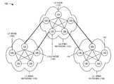
- FIG. 1is a diagram of an example network 100 in which systems and/or methods described herein may be implemented.
- network 100may include a level one (L1) area network 110 , a level two (L2) area network 120 , and another L1 area network 130 .
- Each of networks 110 - 130may include multiple nodes 140 .
- One or more of the devices and/or networks of network 100may interconnect via wired and/or wireless connections.
- Two L1 area networks 110 / 130 , one L2 area network 120 , and fifteen nodes 140have been illustrated in FIG. 1 for simplicity. In practice, there may be more or less L1 area networks 110 / 130 , L2 area networks 120 , and/or nodes 140 .
- one or more of the devices of network 100may perform one or more tasks described as being performed by another one or more of the devices of network 100 .
- L1 area network 110 and L1 area network 130may include one or more of a same type of packet-switched networks, or one or more packet-switched networks of different types.
- a “packet”may refer to a packet, a datagram, or a cell; a fragment of a packet, a fragment of a datagram, or a fragment of a cell; or another type, arrangement, or packaging of data.
- L1 area network 110 and/or L1 area network 130may include one or more of a local area network (LAN), a wide area network (WAN), a metropolitan area network (MAN), an optical network, a cable television network, a satellite television network, a wireless network (e.g., a Code Division Multiple Access (CDMA) network, a general packet radio service (GPRS) network, and/or a Long Term Evolution (LTE) network), an ad hoc network, a telephone network (e.g., the Public Switched Telephone Network (PSTN) or a cellular network), an intranet, the Internet, or a combination of these networks or other types of networks.
- LANlocal area network
- WANwide area network
- MANmetropolitan area network
- CDMACode Division Multiple Access
- GPRSgeneral packet radio service
- LTELong Term Evolution
- PSTNPublic Switched Telephone Network
- intranetthe Internet
- the Internetor a combination of these networks or other types of networks.
- L2 area network 120may include one or more of a same type of packet-switched networks, or one or more packet-switched networks of different types.
- L2 area network 120may include one or more of a LAN, a WAN, a MAN, an optical network, a cable television network, a satellite television network, a wireless network (e.g., a CDMA network, a GPRS network, and/or a LTE network), an ad hoc network, a telephone network (e.g., the PSTN or a cellular network), an intranet, the Internet, or a combination of these networks or other types of networks.
- a wireless networke.g., a CDMA network, a GPRS network, and/or a LTE network
- ad hoc networke.g., a telephone network (e.g., the PSTN or a cellular network), an intranet, the Internet, or a combination of these networks or other types of networks.
- L2 area network 120may include a network (e.g., a WAN) that provides a single bridging domain between L1 area network 110 (e.g., a LAN) and L1 area network 130 (e.g., a LAN).
- a networke.g., a WAN
- L1 area network 110e.g., a LAN
- L1 area network 130e.g., a LAN
- Node 140may include any network device that receives and transmits packets within a network or between networks.
- Node 140may include, for example, a gateway, a router, a switch, a firewall, a network interface card (NIC), a hub, a bridge, a proxy server, an optical add-drop multiplexer (OADM), a broadband remote access server (BRAS), or some other type of network device (e.g., a layer 2 and/or layer 3 device) that processes and/or transfers traffic (e.g., packets).
- Node 140may include one or more ingress interfaces and one or more egress interfaces. Node 140 may receive a packet at one of the ingress interfaces, determine a destination of the received packet, determine an egress interface based on the determined destination, and forward the packet via the determined egress interface.
- nodes 140 that directly connect L1 area networks 110 / 130 with L2 area network 120may be classified as L1/L2 nodes 150 (or network bridges).
- Nodes 140 in L1 area networks 110 / 130 that do not directly connect with L2 area network 120may be classified as L1 nodes 160 .
- Nodes 140 in L2 area network 120 that do not directly connect with L1 area networks 110 / 130may be classified as L2 nodes 170 .
- L1/L2 nodes 150may create Ethernet over IP/GRE tunnels to utilize as a forwarding plane between nodes 140 of L1 area networks 110 / 130 and L2 area network 120 .
- L1/L2 nodes 150may provide an IP/GRE encapsulation header in a packet traveling between L1 area networks 110 / 130 and L2 area network 120 so that the packet may utilize the Ethernet over IP/GRE tunnels.
- the IP/GRE encapsulation headermay include a GRE header portion that provides protocol information, among other information, and may include an IP header portion that provides IP routing between nodes 140 , among other information.
- a node 140may utilize a modified IS-IS protocol to share information with other nodes 140 .
- the modified IS-IS protocolmay utilize existing IP type-length-values (TLVs) for route distribution, may elect redundant multicast root nodes for multicast traffic, and may provide support for multiple area networks and inter-area networks.
- TLVsIP type-length-values
- the modified IS-IS protocolmay propagate LSDB information to the virtual bridging domain in order to discover network topology.
- the modified IS-IS protocolmay move link level addresses to IP level addresses in order to form paths among nodes 140 .
- the modified IS-IS protocolmay reserve multicast addresses (e.g., address “224.0.0.111”) for L1 area networks 110 / 130 nodes 140 , and may reserve different addresses (e.g., address “224.0.1.187”) for L2 area network 120 nodes 140 .
- the modified IS-IS protocolmay randomly select node IP addresses, such as addresses “127.x.x.x,” “169.254.x.x,” or “10.x.x.x.”
- network 100may include fewer devices/networks, different devices/networks, differently arranged devices/networks, or additional devices/networks than depicted in FIG. 1 .
- FIG. 2is a diagram of example components of a device 200 that may correspond to node 140 ( FIG. 1 ).
- node 140may include one or more devices 200 .
- device 200may include input ports 210 , a switching mechanism 220 , output ports 230 , and a control unit 240 .
- Input ports 210may be a point of attachment for physical links and may be a point of entry for incoming traffic, such as packets. Input ports 210 may carry out data link layer encapsulation and decapsulation. In an example implementation, input ports 210 may send and/or receive packets.
- Switching mechanism 220may interconnect input ports 210 with output ports 230 .
- Switching mechanism 220may be implemented using many different techniques.
- switching mechanism 220may be implemented via busses, crossbars, and/or with shared memories which may act as temporary buffers to store traffic from input ports 210 before the traffic is eventually scheduled for delivery to output ports 230 .
- Output ports 230may store packets and may schedule packets for service on output physical links. Output ports 230 may include scheduling algorithms that support priorities and guarantees. Output ports 230 may support data link layer encapsulation and decapsulation, and/or a variety of higher-level protocols. In an example implementation, output ports 230 may send packets and/or receive packets.
- Control unit 240may use routing protocols and one or more forwarding tables for forwarding packets. Control unit 240 may connect with input ports 210 , switching mechanism 220 , and output ports 230 . Control unit 240 may compute a forwarding table, implement routing protocols, and/or run software to configure and manage device 200 . Control unit 240 may handle any packet whose destination address may not be found in the forwarding table.
- control unit 240may include a bus 250 that may include a path that permits communication among a processor 260 , a memory 270 , and a communication interface 280 .
- Processor 260may include one or more processors, microprocessors, application-specific integrated circuit (ASICs), field-programmable gate arrays (FPGAs), or other types of processing units that may interpret and execute instructions.
- Memory 270may include a random access memory (RAM), a read only memory (ROM) device, a magnetic and/or optical recording medium and its corresponding drive, and/or another type of static and/or dynamic storage device that may store information and instructions for execution by processor 260 .
- Memory 270may also temporarily store incoming traffic (e.g., a header of a packet or an entire packet) from input ports 210 , for processing by processor 260 , before a packet is directed back to switching mechanism 220 , queued in switching mechanism 220 , and eventually scheduled to be sent to output ports 230 .
- Communication interface 280may include any transceiver-like mechanism that enables control unit 240 to communicate with other devices and/or systems.
- Device 200may perform certain operations, as described herein. Device 200 may perform these operations in response to processor 260 executing software instructions contained in a computer-readable medium, such as memory 270 .
- a computer-readable mediummay be defined as a non-transitory memory device.
- a memory devicemay include space within a single physical memory device or spread across multiple physical memory devices.
- the software instructionsmay be read into memory 270 from another computer-readable medium, such as a data storage device, or from another device via communication interface 280 .
- the software instructions contained in memory 270may cause processor 260 to perform processes described herein.
- hardwired circuitrymay be used in place of or in combination with software instructions to implement processes described herein. Thus, implementations described herein are not limited to any specific combination of hardware circuitry and software.
- FIG. 2shows example components of device 200
- device 200may include fewer components, different components, differently arranged components, or additional components than depicted in FIG. 2 .
- one or more components of device 200may perform one or more other tasks described as being performed by one or more other components of device 200 .
- FIG. 3is a diagram of example operations capable of being performed by an example portion 300 of network 100 .
- example network portion 300may include L1 area network 110 , L2 area network 120 , L1 area network 130 , and L1/L2 node 150 .
- L1 area network 110 , L2 area network 120 , L1 area network 130 , and L1/L2 node 150may include the features described above in connection with, for example, one or more of FIGS. 1 and 2 .
- L1/L2 node 150may assign a first node prefix to each node 140 of L1 area network 110 , may assign a second node prefix to each node 140 of L2 area network 120 , and may assign a third node prefix to each node 140 of L1 area network 130 .
- L1/L2 node 150may store the assigned node prefixes in a memory (e.g., memory 270 ) associated with L1/L2 node 150 .
- L1/L2 node 150may advertise the second node prefix and the third node prefix (e.g., the node prefixes assigned to networks 120 and 130 ) to L1 area network 110 , as indicated by reference number 310 .
- L1/L2 node 150may advertise the first node prefix and the third node prefix (e.g., the node prefixes assigned to networks 110 and 130 ) to L2 area network 120 , as indicated by reference number 320 .
- L1/L2 node 150may advertise the first node prefix and the second node prefix (e.g., the node prefixes assigned to networks 110 and 120 ) to L1 area network 130 , as indicated by reference number 330 .
- each node prefixmay include a unique area identifier (area-id) that identifies an area network of a node, and a prefix length.
- L1/L2 node 150may advertise the node prefixes to area networks 110 - 130 via one or more IS-IS Hello messages.
- network portion 300may include fewer components, different components, differently arranged components, or additional components than depicted in FIG. 3 .
- one or more components of network portion 300may perform one or more other tasks described as being performed by one or more other components of network portion 300 .
- FIG. 4is a diagram of example functional components of node 140 .
- node 140may include fabric ports 410 , edge ports 420 , a node address 430 , and multiple pseudo node addresses 440 - 1 , . . . , 440 -N (collectively referred to herein as “pseudo node addresses 440 ,” and, in some instances, individually as “pseudo node address 440 ”).
- one or more of the functional components described in connection with FIG. 4may be implemented by one or more of the example components of device 200 ( FIG. 2 ).
- Fabric ports 410may include one or more of input ports 210 and/or output ports 230 ( FIG. 2 ). Fabric ports 410 may attach to a network (e.g., a LAN) that is attached to one or more other bridges. Edge ports 420 may include one or more of input ports 210 and/or output ports 230 ( FIG. 2 ). Edge ports 420 may attach to a network (e.g., a LAN) that is not attached to one or more other bridges. If the network attached to a particular edge port 420 attaches to one or more other bridges, the particular edge port 420 may be classified as a fabric port 410 .
- a networke.g., a LAN
- the particular edge port 420may be classified as a fabric port 410 .
- Node address 430may correspond to a node IP address for fabric ports 410 and a default VLAN associated with node 140 .
- node address 430may be set to a particular IP address (e.g., “169.254.2.3”) for the default VLAN.
- the default VLANmay communicate with a portion of edge ports 420 .
- Pseudo node address 440may correspond to a pseudo node IP address for an additional VLAN associated with node 140 . For example, as shown in FIG.
- pseudo node address 440 - 1may be set to a particular IP address (e.g., “127.1.8.9”) for VLAN-1
- pseudo node address 440 -Nmay be set to a particular IP address (e.g., “127.0.3.7”) for VLAN-N.
- VLAN-1may communicate with a portion of edge ports 420
- VLAN-Nmay communicate with another portion of edge ports 420 .
- node 140may randomly select node address 430 for the default VLAN, and may randomly select pseudo node addresses 440 for any additional VLANs (e.g., VLAN-1, . . . , VLAN-N).
- Node 140may propagate node address 430 and pseudo node addresses 440 to other nodes 140 in an area network (e.g., one of area networks 110 - 130 , FIG. 1 ) via IS-IS Hello messages.
- Node 140may classify a particular port, of node 140 , as a fabric port 410 when the particular port receives an IS-IS Hello message, which may indicate that the particular port is attached to a network (e.g., a LAN) that is attached to one or more other bridges.
- a networke.g., a LAN
- Node 140may classify a particular port, of node 140 , as an edge port 420 when the particular port does not receive an IS-IS Hello message, which may indicate that the particular port is attached to a network (e.g., a LAN) that is not attached to one or more other bridges.
- a networke.g., a LAN
- a particular nodemay select a designated forwarding node from one of nodes 140 based on priorities associated with nodes 140 .
- the designated forwarding nodemay forward traffic from L1/L2 node 150 .
- the prioritiesmay be based on port speeds associated with nodes 140 . If two nodes 140 have the same priority, L1/L2 node 150 may select, as the designated forwarding node, a node 140 with a higher node IP address (e.g., node address 430 ).
- node 140may include fewer functional components, different functional components, differently arranged functional components, or additional functional components than depicted in FIG. 4 .
- one or more functional components of node 140may perform one or more other tasks described as being performed by one or more other functional components of node 140 .
- full mesh topologymay be constructed by calculating paths in an N ⁇ (N ⁇ 1) fashion, where N is a number of nodes 140 in the area network.
- Nis a number of nodes 140 in the area network.
- Each node 140 in the area networkmay calculate paths to all other nodes 140 in the area network, and inter-node traffic may be forwarded via the calculated paths.
- path calculationis an N 2 procedure for each node 140 .
- most trafficmay be provided to a subset of nodes 140 , such as root nodes (also referred to as core nodes, central nodes, or tandem nodes). In such area networks, forcing all nodes 140 to calculate N 2 paths may unnecessarily burden nodes 140 that do not handle traffic other than traffic provided to the root nodes. In other area networks, most traffic may be forced to the root nodes and the root nodes may direct the traffic to other destinations in the area network.
- FIGS. 5A and 5Bdescribe an example method that permits an IS-IS based network to create a set of root nodes and that reduces certain nodes' computational loads so that the IS-IS protocol may be used on thin network devices, such as wireless access points (WAPs).
- WAPswireless access points
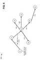
- FIG. 5Ais a diagram of a physical topology of an example network 500 in which systems and/or methods described herein may be implemented.
- network 500may include the features of L1 area network 110 , L2 area network 120 , and/or L1 area network 130 . As shown in FIG.
- network 500may include root nodes 510 - 1 and 510 - 2 (collectively referred to herein as “root nodes 510 ,” and, in some instances, singularly as “root node 510 ”); area nodes 520 - 1 , 520 - 2 , and 520 - 3 (collectively referred to herein as “area nodes 520 ,” and, in some instances, singularly as “area node 520 ”); and edge nodes 530 - 1 , . . . , 530 - 4 (collectively referred to herein as “edge nodes 530 ,” and, in some instances, singularly as “edge node 530 ”).
- root nodes 510 , area nodes 520 , and edge nodes 530may include the features of nodes 140 , described above in connection with, for example, one or more of FIGS. 1-4 .
- One or more of the devices of network 500may interconnect via wired and/or wireless connections.
- Root nodes 510may include nodes (e.g., nodes 140 ) that are capable of forwarding most (or all) of the traffic processed by network 500 .
- Area nodes 520may include nodes (e.g. nodes 140 ) that do not handle traffic in network 500 , other than traffic provided to root nodes 510 .
- Edge nodes 530may include nodes (e.g., nodes 140 ), provided at edges of network 500 , that do not handle traffic in network 500 , other than traffic provided to root nodes 510 .
- Root nodes 510 , area nodes 520 , and edge nodes 530may utilize the IS-IS protocol to indicate or advertise an attribute that includes each node's capability to be a root node (or centralized forwarding node) and each node's priority associated with being a root node. The priority associated with being a root node may be user configurable and may be based on each node's capacity, interface, characteristics, etc.
- Root nodes 510 , area nodes 520 , and edge nodes 530may utilize the IS-IS protocol to indicate or advertise distances from other nodes in network 500 .
- the IS-IS protocolmay propagate each node's attribute and distance metric to other nodes in network 500 .
- Each edge node 530may receive, from root nodes 510 , area nodes 520 , and other edge nodes 530 , the priorities and distances associated with potential root nodes of network 500 (e.g., via the advertised attributes). Each edge node 530 may rank the potential root nodes, based on the received priorities, to create a ranked list of potential root nodes. Edge node 530 may select one or more root nodes (e.g., root nodes 510 - 1 and 510 - 2 ) from the ranked list, based the distances to the potential root nodes, and may calculate shortest paths to the selected root node(s).
- edge node 530may select an active root node and a backup root node for path protection and/or load balancing. Edge node 530 may receive multicast traffic from one or more of the selected root nodes via the calculated shortest paths. Alternatively, or additionally, edge node 530 may receive traffic (e.g., provided to network 500 ), and may provide the traffic to one or more of the selected root nodes via tunnels. The one or more selected root nodes may forward the traffic within network 500 or outside of network 500 . In one example implementation, area nodes 520 may perform operations similar to the aforementioned operations performed by edge nodes 530 .
- FIG. 5Bis a diagram of an overlay topology of example network 500 , after edge nodes 530 have selected root nodes (e.g., root nodes 510 - 1 and 510 - 2 ) for network 500 .
- overlay paths 540may be provided between root nodes 510 - 1 / 510 - 2 and each of area nodes 520 and edge nodes 530 .
- Overlay paths 540may correspond to the calculated shortest paths to root nodes 510 - 1 and 510 - 2 .
- Each root node 510may calculate paths (e.g., overlay paths 540 ) to all nodes in network 500 and may select a shortest path to each node of network 500 .
- the IS-IS protocolmay ensure that there are no loops in end-to-end forwarding paths of edge nodes 530 .
- Tunnelingmay be used where node addresses are placed in tunnel headers.
- Root nodes 510may act as tandem nodes in edge-to-edge forwarding. Multiple root nodes may form a tandem hierarchy based on the priorities in the attributes.
- the method described above with respect to FIGS. 5A and 5Bmay reduce computational loads (e.g., due to shortest path calculations) on edge nodes 530 even when network 500 includes a large number of nodes.
- the reduced computational loadsmay enable network 500 to utilize thin network devices, such as WAPs, as edge nodes 530 .
- the methodmay permit extra control for directing traffic to a subset of nodes in network, and may provide more flexibility to network 500 for controlling traffic forwarding.
- network 500may include fewer components, different components, differently arranged components, or additional components than depicted in FIGS. 5A and 5B .
- one or more components of network 500may perform one or more other tasks described as being performed by one or more other components of network 500 .
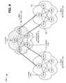
- FIG. 6is a diagram of example multicast forwarding operations capable of being performed by an example network 600 in which systems and/or methods described herein may be implemented.
- network 600may form a multicast distribution tree that includes root nodes C1 and C2, area nodes A1 and A2, and edge nodes E1, E2, E3, and E4.
- root nodes C1/C2, area nodes A1/A2, and edge nodes E1-E4may include the features of nodes 140 , described above in connection with, for example, one or more of FIGS. 1-5B .
- One or more of the devices of network 600may interconnect via wired and/or wireless connections.
- Multicast root nodes C1/C2may include the features of root nodes 510 described above in connection with FIGS. 5A and 5B .
- Area nodes A1/A2may include the features of area nodes 520 described above in connection with FIGS. 5A and 5B .
- Edge nodes E1-E4may include the features of edge nodes 530 described above in connection with FIGS. 5A and 5B .
- multicast root nodes C1 and C2may advertise (e.g., via the attribute described above in connection with FIGS. 5A and 5B ), to other nodes in network 600 , that root nodes C1 and C2 are capable of being root nodes for multicast traffic.
- Edge node E1may select root node C1 as a root node for multicast traffic.
- edge node E1may select root node C1 based on priority information (e.g., distance, bandwidth, etc.) associated with root node C1.
- Edge node E1may designate root node C2 as a redundant or backup root node for multicast traffic, which may help with load balancing of multicast traffic in network 600 .
- edge node E1may be a source of multicast (MC) traffic, as indicated by reference number 610 , and may provide multicast traffic 620 directly to root node C1, via a tunnel.
- Root node C1may receive multicast traffic 620 from edge node E1, and may forward multicast traffic 620 to other nodes of network 600 on a hop-by-hop basis. For example, root node C1 may forward multicast traffic 620 to area node A1, and area node A1 may forward multicast traffic 620 to edge nodes E2 and E3, root node C2, and area node A2.
- Edge node E3may forward multicast traffic 620 to edge node E4.
- root node C1may forward multicast traffic 620 to other nodes of network 600 using a unicast tunnel header and using reverse path forwarding (RPF) to prevent looping.
- RPFreverse path forwarding
- each node in the hop-by-hop pathmay perform path pruning and each edge node may perform VLAN pruning.
- network 600may include fewer components, different components, differently arranged components, or additional components than depicted in FIG. 6 .
- one or more components of network 600may perform one or more other tasks described as being performed by one or more other components of network 600 .
- FIG. 7is a diagram of example operations capable of being performed by another example network 700 in which systems and/or methods described herein may be implemented.
- network 700may include the features of L1 area network 110 , L2 area network 120 , and/or L1 area network 130 .
- network 700may include a group of access nodes 140 interconnected with a group of core nodes 140 .
- One or more of the devices of network 700may interconnect via wired and/or wireless connections.
- Access nodes 140may include the features of nodes 140 , as described above in connection with, for example, one or more of FIGS. 1-6 .
- Access node 140may include a network device, such as a gateway, a router, a switch, a firewall, a NIC, a hub, a bridge, a proxy server, an OADM, or some other type of device that processes and/or transfers traffic.
- access node 140may include a device that is capable of transmitting information to and/or receiving information from core nodes 140 .
- access node 140may provide client devices (not shown) with access to network 700 .
- Core nodes 140may include the features of nodes 140 , as described above in connection with, for example, one or more of FIGS. 1-6 .
- Core nodes 140may include one or more computation or communication devices, that gather, process, and/or provide information in a manner described herein.
- core node 140may include a server device, a laptop computer, a personal computer, a workstation computer, a network device, etc.
- core node 140may include a device that is capable of transmitting information to and/or receiving information from access nodes 140 .
- core nodes 140may correspond to aggregation nodes provided in an aggregation layer of network 700 .
- each core node 140may have ECMP next-hops 710 to each of access nodes 140 .
- Each access node 140may have ECMP next-hops 720 to each of core nodes 140 .
- each nodemay have a maximum of N ⁇ 1 independent ECMP next-hops.
- ECMP next-hops 710 / 720may be created via the modified IS-IS protocol, and may provide flexible hop-by-hop multi-path next-hops.
- ECMP next-hops 710 / 720may provide enough entropy to permit independent path specifications (e.g., MAC address, IP address, etc.).
- ECMP next-hops 710 / 720may be based on a tunnel IP header that includes original layer 2, layer 3, and layer 4 headers.
- ECMP next-hops 710 / 720may be based on a header that includes passenger layer 2, layer 3, and layer 4 headers.
- network 700may include fewer components, different components, differently arranged components, or additional components than depicted in FIG. 7 .
- ECMP next-hops 710 / 720may be replaced with and/or multi-chassis link aggregation group (MC-LAG) next-hops.
- M-LAGmulti-chassis link aggregation group
- one or more components of network 700may perform one or more other tasks described as being performed by one or more other components of network 700 .
- FIG. 8is a diagram of a first example configuration type 800 for network 100 ( FIG. 1 ).
- first configuration type 800may include L1 area network 110 , L2 area network 120 , L1 area network 130 , nodes 140 , L1/L2 nodes 150 , L1 nodes 160 , and L2 nodes 170 .
- L1 area network 110 , L2 area network 120 , L1 area network 130 , nodes 140 , L1/L2 nodes 150 , L1 nodes 160 , and L2 nodes 170may include the features described above in connection with, for example, one or more of FIGS. 1-7 .
- L2 area network 120may correspond to a WAN 810 that provides an interconnect mechanism between L1 area network 110 and L1 area network 130 .
- WAN 810may provide a single bridging domain across multiple campus networks (e.g., L1 area networks 110 / 130 ).
- L1 nodes 160may calculate routes to L1/L2 nodes 150 for inter-area traffic, and inter-area traffic may be IP routed through L2 nodes 170 .
- L2 nodes 170may have routes to all areas, and the modified IS-IS protocol may ensure that traffic is loop free among L2 nodes 170 .
- first configuration type 800may include fewer components, different components, differently arranged components, or additional components than depicted in FIG. 8 .
- one or more components of first configuration type 800may perform one or more other tasks described as being performed by one or more other components of first configuration type 800 .
- FIG. 9is a diagram of a second example configuration type 900 for network 100 (FIG. 1 ).
- second configuration type 900may include L1 area network 110 , L2 area network 120 , L1 area network 130 , nodes 140 , L1/L2 nodes 150 , L1 nodes 160 , and L2 nodes 170 .
- L1 area network 110 , L2 area network 120 , L1 area network 130 , nodes 140 , L1/L2 nodes 150 , L1 nodes 160 , and L2 nodes 170may include the features described above in connection with, for example, one or more of FIGS. 1-8 .
- L2 area network 120may correspond to an IP routed network 910 that provides an interconnect mechanism between L1 area network 110 and L1 area network 130 .
- IP routed network 910may not implement the modified IS-IS protocol.
- second configuration type 900may include fewer components, different components, differently arranged components, or additional components than depicted in FIG. 9 .
- one or more components of second configuration type 900may perform one or more other tasks described as being performed by one or more other components of second configuration type 900 .
- FIG. 10is a diagram of a third example configuration type 1000 for network 100 ( FIG. 1 ).
- third configuration type 1000may include L1 area network 110 , L2 area network 120 , L1 area network 130 , nodes 140 , L1/L2 nodes 150 , L1 nodes 160 , and L2 nodes 170 .
- L1 area network 110 , L2 area network 120 , L1 area network 130 , nodes 140 , L1/L2 nodes 150 , L1 nodes 160 , and L2 nodes 170may include the features described above in connection with, for example, one or more of FIGS. 1-9 .
- L2 area network 120may correspond to a multiprotocol label switching (MPLS) network 1010 that provides an interconnect mechanism between L1 area network 110 and L1 area network 130 .
- MPLS network 1010may provide a single bridging domain across multiple networks (e.g., L1 area networks 110 / 130 ).
- L1/L2 nodes 150may advertise MPLS transport labels to MPLS network 1010 , may map L2-to-L2 paths to MPLS pseudo wires (PWs), and may advertise the MPLS PWs to MPLS network 1010 .
- Each L2 node 170may perform a PW label exchange with other L2 nodes 170 in order to define a full mesh of PW labels.
- the PW label exchangemay enable MPLS network 1010 to better load balance traffic.
- the modified IS-IS protocolmay provide Hello packets over the PWs.
- IS-IS exchangemay indicate a link type (e.g., MPLS), and may include a value of a MPLS transport label.
- Each L2 node 170may encapsulate passenger packets with a path's MPLS PW tunnel label stack.
- third configuration type 1000may include fewer components, different components, differently arranged components, or additional components than depicted in FIG. 10 .
- one or more components of third configuration type 1000may perform one or more other tasks described as being performed by one or more other components of third configuration type 1000 .
- FIG. 11is a diagram of example functional components of node 140 .
- node 140may include fabric ports 410 , edge ports 420 , a fabric interface 1105 , an egress processing component 1110 , an egress packet editing component 1115 , a route engine 1120 , a bridge engine 1125 , an interface assignment/tunnel termination component 1130 , and tables 1135 - 1145 .
- one or more of the functional components described in connection with FIG. 4may be implemented by one or more of the example components of device 200 ( FIG. 2 ).
- Fabric ports 410 and edge ports 420may include the features described above in connection with FIG. 4 .
- Fabric interface 1105may include a switching or interface component that may allow efficient communication between components of node 140 (e.g., fabric ports 410 and edge ports 420 ).
- Egress processing component 1110may provide an interface to tables (e.g., table 1145 ) and may enable components of node 140 to communicate with the tables.
- Egress packet editing component 1115may provide an interface to tables (e.g., for altering headers of packets) and may enable components of node 140 to communicate with the tables.
- Route engine 1120may include a component that may perform high level management functions for node 140 .
- route engine 1120may communicate with other networks and network devices connected to node 140 to exchange information regarding network topology.
- Route engine 1120may create routing tables based on network topology information and forwarding tables based on the routing tables.
- Route engine 1120may also perform other general control and monitoring functions for node 140 .
- route engine 1120may route traffic between one or more fabric ports 410 and/or edge ports 420 .
- Bridge engine 1125may include a component that may perform management functions, associated with inter-area communications, for node 140 .
- bridge engine 1125may communicate with other networks and network devices, connected to node 140 , in order to exchange inter-area communications.
- Interface assignment/tunnel termination component 1130may include a component that assigns an interface of node 140 to traffic received by fabric ports 410 and/or edge ports 420 . Interface assignment/tunnel termination component 1130 may provide a termination point for tunnels associated with node 140 .
- Table 1135may include a forwarding database (FDB) table that may store MAC addresses that have been learned and from which ports that the MAC addresses were learned.
- Table 1140may include a table that identifies a downstream interface for a packet. For example, table 1140 may identify a downstream interface via a trunk field and a pointer field.
- Table 1145may include a header alteration table that provides information to alter a header of a packet processed by node 140 .
- FDBforwarding database
- node 140may provide a path 1150 for local switching traffic received by edge port 420 of node 140 .
- Path 1150may route the local switching traffic from edge port 420 to bridge engine 1125 , via interface assignment/tunnel termination component 1130 .
- Bridge engine 1125may interact with table 1135 , and may route the local switching traffic to another edge port 420 , via egress packet editing component 1115 .
- Node 140may provide a path 1155 for remote switching traffic received by edge port 420 of node 140 .
- Path 1155may route the remote switching traffic from edge port 420 to bridge engine 1125 , via interface assignment/tunnel termination component 1130 .
- Bridge engine 1125may interact with table 1135 , and may route the remote switching traffic to egress processing component 1110 .
- Egress processing component 1110may interact with table 1140 , and may route the remote switching traffic to egress packet editing component 1115 .
- Egress packet editing component 1115may interact with table 1145 , and may route the remote switching traffic to fabric port 410 .
- Node 140may provide a path 1160 for fabric-to-edge traffic received by fabric port 410 of node 140 .
- Path 1160may route the fabric-to-edge traffic from fabric port 410 to bridge engine 1125 , via interface assignment/tunnel termination component 1130 .
- Bridge engine 1125may interact with table 1135 , and may route the fabric-to-edge traffic to edge port 420 , via egress packet editing component 1115 .
- Node 140may provide a path 1165 for fabric transit traffic received by fabric port 410 of node 140 .
- Path 1165may route the fabric transit traffic from fabric port 410 to bridge engine 1125 , via interface assignment/tunnel termination component 1130 .
- Bridge engine 1125may interact with table 1135 , and may route the fabric transit traffic to route engine 1120 .
- Route engine 1120may route the fabric transit traffic to egress processing component 1110 , and egress processing component 1110 may route the fabric transit traffic to another fabric port 410 , via egress packet editing component 1115 .
- Node 140may provide a path 1170 for root-to-fabric traffic received by fabric port 410 of node 140 .
- Path 1170may route the root-to-fabric traffic from fabric port 410 to bridge engine 1125 , via interface assignment/tunnel termination component 1130 .
- Bridge engine 1125may interact with table 1135 , and may route the root-to-fabric traffic to egress processing component 1110 .
- Egress processing component 1110may interact with table 1140 , and may route the root-to-fabric traffic to egress packet editing component 1115 .
- Egress packet editing component 1115may interact with table 1145 , and may route the root-to-fabric traffic to another fabric port 410 .
- node 140may include fewer functional components, different functional components, differently arranged functional components, or additional functional components than depicted in FIG. 11 .
- one or more functional components of node 140may perform one or more other tasks described as being performed by one or more other functional components of node 140 .
- FIG. 12is a flow chart of an example process 1200 for forming a multi-device switched fabric using IP-routed or switched networks according to an implementation described herein.
- process 1200may be performed by L1/L2 node 150 .
- some or all of process 1200may be performed by one or more devices other than L1/L2 node 150 or in combination with L1/L2 node 150 .
- One or more of the process blocks depicted in FIG. 12may be performed concurrently and independently of one or more other process blocks.
- process 1200may include associating a first node prefix with each node in a first area network (block 1210 ), associating a second node prefix with each node in a second area network (block 1220 ), and associating a third node prefix with each node in a third area network (block 1230 ).
- L1/L2 node 150may assign a first node prefix to each node 140 of L1 area network 110 , may assign a second node prefix to each node 140 of L2 area network 120 , and may assign a third node prefix to each node 140 of L1 area network 130 .
- L1/L2 node 150may store the assigned node prefixes in a memory (e.g., memory 270 ) associated with L1/L2 node 150 .
- process 1200may include advertising the first node prefix to the second and third area networks (block 1240 ), advertising the second node prefix to the first and third area networks (block 1250 ), and advertising the third node prefix to the first and second area networks (block 1260 ).
- L1/L2 node 150may advertise the second node prefix and the third node prefix (e.g., the node prefixes assigned to networks 120 and 130 ) to L1 area network 110 , as indicated by reference number 310 .
- L1/L2 node 150may advertise the first node prefix and the third node prefix (e.g., the node prefixes assigned to networks 110 and 130 ) to L2 area network 120 , as indicated by reference number 320 .
- L1/L2 node 150may advertise the first node prefix and the second node prefix (e.g., the node prefixes assigned to networks 110 and 120 ) to L1 area network 130 , as indicated by reference number 330 .
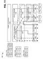
- FIG. 13is a flow chart of an example process 1300 for propagating node IP addresses and for classifying ports according to an implementation described herein.
- process 1300may be performed by node 140 .
- some or all of process 1300may be performed by one or more devices other than node 140 or in combination with node 140 .
- One or more of the process blocks depicted in FIG. 13may be performed concurrently and independently of one or more other process blocks.
- process 1300may include randomly selecting a node IP address for a default VLAN (block 1310 ), and determining whether there is an additional VLAN (block 1320 ). If there is an additional VLAN (block 1320 —YES), process 1300 may include randomly selecting a pseudo node IP address for the additional VLAN (block 1330 ). For example, in an implementation described above in connection with FIG. 4 , node 140 may randomly select node address 430 for the default VLAN, and may randomly select pseudo node addresses 440 for any additional VLANs (e.g., VLAN-1, . . . , VLAN-N).
- VLAN-1e.g., VLAN-1, . . . , VLAN-N
- process 1300may include propagating the node IP address and the pseudo node IP address to other nodes in an area network (block 1340 ), classifying a port as a fabric port when the port receives a Hello message (block 1350 ), and classifying a port as an edge port when the port does not receive a Hello message (block 1360 ).
- node 140may propagate node address 430 and pseudo node addresses 440 to other nodes 140 in an area network (e.g., one of area networks 110 - 130 , FIG. 1 ) via IS-IS Hello messages.
- Node 140may classify a particular port, of node 140 , as a fabric port 410 when the particular port receives an IS-IS Hello message, which may indicate that the particular port is attached to a network (e.g., a LAN) that is attached to one or more other bridges.
- Node 140may classify a particular port, of node 140 , as an edge port 420 when the particular port does not receive an IS-IS Hello message, which may indicate that the particular port is attached to a network (e.g., a LAN) that is not attached to one or more other bridges.
- FIG. 14is a flow chart of an example process 1400 for routing traffic from a particular root node via a calculated shortest path.
- process 1400may be performed by edge node 530 .
- some or all of process 1400may be performed by one or more devices other than edge node 530 (e.g., area node 520 ) or in combination with edge node 530 .
- One or more of the process blocks depicted in FIG. 14may be performed concurrently and independently of one or more other process blocks.
- process 1400may include receiving priorities and/or distances associated with potential root nodes of a network (block 1410 ), and ranking the root nodes based on the priorities to create a ranked list of potential root nodes (block 1420 ).
- each edge node 530may receive, from root nodes 510 , area nodes 520 , and other edge nodes 530 , the priorities and distances associated with potential root nodes of network 500 (e.g., via the advertised attributes).
- Each edge node 530may rank the potential root nodes, based on the received priorities, to create a ranked list of potential root nodes.
- process 1400may include selecting a particular root node from the ranked list based on distances to the potential rood nodes (block 1430 ), and calculating a shortest path to the particular root node (block 1440 ).
- edge node 530may select one or more root nodes (e.g., root nodes 510 - 1 and 510 - 2 ) from the ranked list, based the distances to the potential root nodes, and may calculate shortest paths to the selected root node(s).
- edge node 530may select an active root node and a backup root node for path protection and/or load balancing. Such an arrangement may significantly reduce a computational load on edge node 530 .
- process 1400may include receiving multicast traffic from the particular root node via the calculated shortest path (block 1450 ). Alternatively, or additionally, process 1400 may include receiving traffic (block 1460 ), and providing the traffic to the particular root node via a tunnel, where the particular root node forwards the traffic to other nodes (block 1470 ).
- Edge node 530may receive multicast traffic from one or more of the selected root nodes via the calculated shortest paths. Alternatively, or additionally, edge node 530 may receive traffic, and may provide the traffic to one or more of the selected root nodes via tunnels. The one or more selected root nodes may forward the traffic within network 500 or outside of network 500 .
- Systems and/or methods described hereinmay provide a virtual bridging architecture that enables multiple network devices (or nodes) to automatically form multiple shortest paths among the multiple nodes without loops.
- the multiple shortest pathsmay span across a variety of networks (e.g., legacy switched and routed networks) and may construct a virtual bridging domain that appears as a single network device.
- the systems and/or methodsmay utilize Ethernet over IP/GRE tunnels at edge nodes to act as a forwarding plane between nodes, and may utilize a modified IS-IS protocol to propagate LSDB information to the virtual bridging domain and to discover network topology.
- the systems and/or methodsmay utilize ECMP routing as a basis for creating the multiple shortest paths among the multiple nodes.
- the systems and/or methodsmay address the scalability, resiliency, and efficiency issues associated with network bridges, and may be deployed using existing chipsets and existing network devices.
- the term componentis intended to be broadly construed to include hardware (e.g., a processor, a microprocessor, an ASIC, a FPGA, a chip, a memory device (e.g., a ROM, a RAM, etc.), etc.) or a combination of hardware and software (e.g., a processor, microprocessor, ASIC, etc. executing software contained in a memory device).
- hardwaree.g., a processor, a microprocessor, an ASIC, a FPGA, a chip
- a memory devicee.g., a ROM, a RAM, etc.
- softwaree.g., a processor, microprocessor, ASIC, etc. executing software contained in a memory device.
Landscapes
- Engineering & Computer Science (AREA)
- Computer Networks & Wireless Communication (AREA)
- Signal Processing (AREA)
- Data Exchanges In Wide-Area Networks (AREA)
Abstract
Description
Claims (20)
Priority Applications (1)
| Application Number | Priority Date | Filing Date | Title |
|---|---|---|---|
| US13/207,988US8798055B1 (en) | 2011-08-11 | 2011-08-11 | Forming a multi-device layer 2 switched fabric using internet protocol (IP)-routed / switched networks |
Applications Claiming Priority (1)
| Application Number | Priority Date | Filing Date | Title |
|---|---|---|---|
| US13/207,988US8798055B1 (en) | 2011-08-11 | 2011-08-11 | Forming a multi-device layer 2 switched fabric using internet protocol (IP)-routed / switched networks |
Publications (1)
| Publication Number | Publication Date |
|---|---|
| US8798055B1true US8798055B1 (en) | 2014-08-05 |
Family
ID=51229100
Family Applications (1)
| Application Number | Title | Priority Date | Filing Date |
|---|---|---|---|
| US13/207,988Expired - Fee RelatedUS8798055B1 (en) | 2011-08-11 | 2011-08-11 | Forming a multi-device layer 2 switched fabric using internet protocol (IP)-routed / switched networks |
Country Status (1)
| Country | Link |
|---|---|
| US (1) | US8798055B1 (en) |
Cited By (74)
| Publication number | Priority date | Publication date | Assignee | Title |
|---|---|---|---|---|
| US20130132499A1 (en)* | 2011-11-22 | 2013-05-23 | Huawei Technologies Co., Ltd. | Method and system for auto-configuartion, and network node |
| US20130250956A1 (en)* | 2012-03-22 | 2013-09-26 | Yi Sun | Non-fragmented ip packet tunneling in a network |
| US20130343386A1 (en)* | 2012-06-21 | 2013-12-26 | Cisco Technology, Inc. | First hop load balancing |
| US20150023352A1 (en)* | 2012-02-08 | 2015-01-22 | Hangzhou H3C Technologies Co., Ltd. | Implement equal cost multiple path of trill network |
| US20150055652A1 (en)* | 2013-08-23 | 2015-02-26 | Futurewei Technologies, Inc. | Multi-Destination Traffic Control in Multi-Level Networks |
| US9294442B1 (en) | 2015-03-30 | 2016-03-22 | Varmour Networks, Inc. | System and method for threat-driven security policy controls |
| US20160127225A1 (en)* | 2014-10-29 | 2016-05-05 | Cisco Technology, Inc., A Corporation Of California | Label-switched Packets with Device-independent Labels |
| US9380027B1 (en) | 2015-03-30 | 2016-06-28 | Varmour Networks, Inc. | Conditional declarative policies |
| US20160269284A1 (en)* | 2013-11-25 | 2016-09-15 | Huawei Technologies Co., Ltd. | Packet forwarding method and apparatus |
| US9483317B1 (en) | 2015-08-17 | 2016-11-01 | Varmour Networks, Inc. | Using multiple central processing unit cores for packet forwarding in virtualized networks |
| US9521115B1 (en) | 2016-03-24 | 2016-12-13 | Varmour Networks, Inc. | Security policy generation using container metadata |
| US9525697B2 (en) | 2015-04-02 | 2016-12-20 | Varmour Networks, Inc. | Delivering security functions to distributed networks |
| US9609083B2 (en) | 2011-02-10 | 2017-03-28 | Varmour Networks, Inc. | Distributed service processing of network gateways using virtual machines |
| US9680852B1 (en) | 2016-01-29 | 2017-06-13 | Varmour Networks, Inc. | Recursive multi-layer examination for computer network security remediation |
| US9742732B2 (en) | 2012-03-12 | 2017-08-22 | Varmour Networks, Inc. | Distributed TCP SYN flood protection |
| US9762599B2 (en) | 2016-01-29 | 2017-09-12 | Varmour Networks, Inc. | Multi-node affinity-based examination for computer network security remediation |
| US9800471B2 (en) | 2014-05-13 | 2017-10-24 | Brocade Communications Systems, Inc. | Network extension groups of global VLANs in a fabric switch |
| US9806906B2 (en) | 2010-06-08 | 2017-10-31 | Brocade Communications Systems, Inc. | Flooding packets on a per-virtual-network basis |
| US9807031B2 (en) | 2010-07-16 | 2017-10-31 | Brocade Communications Systems, Inc. | System and method for network configuration |
| US9807017B2 (en) | 2013-01-11 | 2017-10-31 | Brocade Communications Systems, Inc. | Multicast traffic load balancing over virtual link aggregation |
| US9807007B2 (en) | 2014-08-11 | 2017-10-31 | Brocade Communications Systems, Inc. | Progressive MAC address learning |
| US9806949B2 (en) | 2013-09-06 | 2017-10-31 | Brocade Communications Systems, Inc. | Transparent interconnection of Ethernet fabric switches |
| US9848040B2 (en) | 2010-06-07 | 2017-12-19 | Brocade Communications Systems, Inc. | Name services for virtual cluster switching |
| US9871676B2 (en) | 2013-03-15 | 2018-01-16 | Brocade Communications Systems LLC | Scalable gateways for a fabric switch |
| US9887916B2 (en) | 2012-03-22 | 2018-02-06 | Brocade Communications Systems LLC | Overlay tunnel in a fabric switch |
| US9912612B2 (en)* | 2013-10-28 | 2018-03-06 | Brocade Communications Systems LLC | Extended ethernet fabric switches |
| US9912614B2 (en) | 2015-12-07 | 2018-03-06 | Brocade Communications Systems LLC | Interconnection of switches based on hierarchical overlay tunneling |
| US9942173B2 (en) | 2010-05-28 | 2018-04-10 | Brocade Communications System Llc | Distributed configuration management for virtual cluster switching |
| US9942097B2 (en) | 2015-01-05 | 2018-04-10 | Brocade Communications Systems LLC | Power management in a network of interconnected switches |
| US9973472B2 (en) | 2015-04-02 | 2018-05-15 | Varmour Networks, Inc. | Methods and systems for orchestrating physical and virtual switches to enforce security boundaries |
| US9998365B2 (en) | 2012-05-18 | 2018-06-12 | Brocade Communications Systems, LLC | Network feedback in software-defined networks |
| US10003552B2 (en) | 2015-01-05 | 2018-06-19 | Brocade Communications Systems, Llc. | Distributed bidirectional forwarding detection protocol (D-BFD) for cluster of interconnected switches |
| US10009381B2 (en) | 2015-03-30 | 2018-06-26 | Varmour Networks, Inc. | System and method for threat-driven security policy controls |
| US10038592B2 (en) | 2015-03-17 | 2018-07-31 | Brocade Communications Systems LLC | Identifier assignment to a new switch in a switch group |
| US10063473B2 (en) | 2014-04-30 | 2018-08-28 | Brocade Communications Systems LLC | Method and system for facilitating switch virtualization in a network of interconnected switches |
| US10075394B2 (en) | 2012-11-16 | 2018-09-11 | Brocade Communications Systems LLC | Virtual link aggregations across multiple fabric switches |
| US10091238B2 (en) | 2014-02-11 | 2018-10-02 | Varmour Networks, Inc. | Deception using distributed threat detection |
| US10164795B1 (en)* | 2014-02-28 | 2018-12-25 | Juniper Networks, Inc. | Forming a multi-device layer 2 switched fabric using internet protocol (IP)-router / switched networks |
| US10164883B2 (en) | 2011-11-10 | 2018-12-25 | Avago Technologies International Sales Pte. Limited | System and method for flow management in software-defined networks |
| US10171303B2 (en) | 2015-09-16 | 2019-01-01 | Avago Technologies International Sales Pte. Limited | IP-based interconnection of switches with a logical chassis |
| US10193929B2 (en) | 2015-03-13 | 2019-01-29 | Varmour Networks, Inc. | Methods and systems for improving analytics in distributed networks |
| US10191758B2 (en) | 2015-12-09 | 2019-01-29 | Varmour Networks, Inc. | Directing data traffic between intra-server virtual machines |
| US10237090B2 (en) | 2016-10-28 | 2019-03-19 | Avago Technologies International Sales Pte. Limited | Rule-based network identifier mapping |
| US10264025B2 (en) | 2016-06-24 | 2019-04-16 | Varmour Networks, Inc. | Security policy generation for virtualization, bare-metal server, and cloud computing environments |
| US10277464B2 (en) | 2012-05-22 | 2019-04-30 | Arris Enterprises Llc | Client auto-configuration in a multi-switch link aggregation |
| US10355879B2 (en) | 2014-02-10 | 2019-07-16 | Avago Technologies International Sales Pte. Limited | Virtual extensible LAN tunnel keepalives |
| US10419276B2 (en) | 2010-06-07 | 2019-09-17 | Avago Technologies International Sales Pte. Limited | Advanced link tracking for virtual cluster switching |
| US10439929B2 (en) | 2015-07-31 | 2019-10-08 | Avago Technologies International Sales Pte. Limited | Graceful recovery of a multicast-enabled switch |
| US10462049B2 (en) | 2013-03-01 | 2019-10-29 | Avago Technologies International Sales Pte. Limited | Spanning tree in fabric switches |
| US10476698B2 (en) | 2014-03-20 | 2019-11-12 | Avago Technologies International Sales Pte. Limited | Redundent virtual link aggregation group |
| US10579406B2 (en) | 2015-04-08 | 2020-03-03 | Avago Technologies International Sales Pte. Limited | Dynamic orchestration of overlay tunnels |
| US10581758B2 (en) | 2014-03-19 | 2020-03-03 | Avago Technologies International Sales Pte. Limited | Distributed hot standby links for vLAG |
| US10616108B2 (en) | 2014-07-29 | 2020-04-07 | Avago Technologies International Sales Pte. Limited | Scalable MAC address virtualization |
| US10673703B2 (en) | 2010-05-03 | 2020-06-02 | Avago Technologies International Sales Pte. Limited | Fabric switching |
| US10755334B2 (en) | 2016-06-30 | 2020-08-25 | Varmour Networks, Inc. | Systems and methods for continually scoring and segmenting open opportunities using client data and product predictors |
| US10887173B2 (en) | 2016-12-21 | 2021-01-05 | Juniper Networks, Inc. | Communicating state information in distributed operating systems |
| US10904035B2 (en)* | 2019-06-03 | 2021-01-26 | Arista Networks, Inc. | Method and system for processing encapsulated wireless traffic |
| US11075806B1 (en)* | 2016-06-30 | 2021-07-27 | Juniper Networks, Inc. | Hierarchical naming scheme for state propagation within network devices |
| US11095742B2 (en) | 2019-03-27 | 2021-08-17 | Juniper Networks, Inc. | Query proxy for delivery of dynamic system state |
| US11290494B2 (en) | 2019-05-31 | 2022-03-29 | Varmour Networks, Inc. | Reliability prediction for cloud security policies |
| US11290493B2 (en) | 2019-05-31 | 2022-03-29 | Varmour Networks, Inc. | Template-driven intent-based security |
| US11310284B2 (en) | 2019-05-31 | 2022-04-19 | Varmour Networks, Inc. | Validation of cloud security policies |
| US11316775B2 (en) | 2016-12-21 | 2022-04-26 | Juniper Networks, Inc. | Maintaining coherency in distributed operating systems for network devices |
| US11316744B2 (en) | 2016-12-21 | 2022-04-26 | Juniper Networks, Inc. | Organizing execution of distributed operating systems for network devices |
| US20220255903A1 (en)* | 2021-02-10 | 2022-08-11 | SecureCo, Inc. | Secure network protocol and transit system to protect communications deliverability and attribution |
| US11575563B2 (en) | 2019-05-31 | 2023-02-07 | Varmour Networks, Inc. | Cloud security management |
| US11711374B2 (en) | 2019-05-31 | 2023-07-25 | Varmour Networks, Inc. | Systems and methods for understanding identity and organizational access to applications within an enterprise environment |
| US11734316B2 (en) | 2021-07-08 | 2023-08-22 | Varmour Networks, Inc. | Relationship-based search in a computing environment |
| US11777978B2 (en) | 2021-01-29 | 2023-10-03 | Varmour Networks, Inc. | Methods and systems for accurately assessing application access risk |
| US11818152B2 (en) | 2020-12-23 | 2023-11-14 | Varmour Networks, Inc. | Modeling topic-based message-oriented middleware within a security system |
| US11825350B2 (en) | 2020-10-26 | 2023-11-21 | Charter Communications Operating, Llc | System and method for establishing a virtual access point |
| US11863580B2 (en) | 2019-05-31 | 2024-01-02 | Varmour Networks, Inc. | Modeling application dependencies to identify operational risk |
| US11876817B2 (en) | 2020-12-23 | 2024-01-16 | Varmour Networks, Inc. | Modeling queue-based message-oriented middleware relationships in a security system |
| US12050693B2 (en) | 2021-01-29 | 2024-07-30 | Varmour Networks, Inc. | System and method for attributing user behavior from multiple technical telemetry sources |
Citations (6)
| Publication number | Priority date | Publication date | Assignee | Title |
|---|---|---|---|---|
| US20060146845A1 (en)* | 2004-12-30 | 2006-07-06 | Alcatel | Spanning tree protocol with burst avoidance |
| US20070204021A1 (en)* | 2006-02-28 | 2007-08-30 | Ekl Randy L | Method and apparatus for myopic root node selection in an ad hoc network |
| US20080144644A1 (en)* | 2006-12-14 | 2008-06-19 | Nortel Networks Limited | Method and apparatus for exchanging routing information and the establishment of connectivity across multiple network areas |
| US20080285489A1 (en)* | 1991-11-12 | 2008-11-20 | Broadcom Corporation | Redundant radio frequency network having a roaming terminal communication protocol |
| US20090168666A1 (en)* | 2007-12-31 | 2009-07-02 | Nortel Networks Limited | Implementation of VPNs over a link state protocol controlled Ethernet network |
| US20110007667A1 (en)* | 2008-03-04 | 2011-01-13 | Takacs Attila | system and method of automatically configuring i-sids in gmpls controlled eternet provider backbone bridged networks |
- 2011
- 2011-08-11USUS13/207,988patent/US8798055B1/ennot_activeExpired - Fee Related
Patent Citations (6)
| Publication number | Priority date | Publication date | Assignee | Title |
|---|---|---|---|---|
| US20080285489A1 (en)* | 1991-11-12 | 2008-11-20 | Broadcom Corporation | Redundant radio frequency network having a roaming terminal communication protocol |
| US20060146845A1 (en)* | 2004-12-30 | 2006-07-06 | Alcatel | Spanning tree protocol with burst avoidance |
| US20070204021A1 (en)* | 2006-02-28 | 2007-08-30 | Ekl Randy L | Method and apparatus for myopic root node selection in an ad hoc network |
| US20080144644A1 (en)* | 2006-12-14 | 2008-06-19 | Nortel Networks Limited | Method and apparatus for exchanging routing information and the establishment of connectivity across multiple network areas |
| US20090168666A1 (en)* | 2007-12-31 | 2009-07-02 | Nortel Networks Limited | Implementation of VPNs over a link state protocol controlled Ethernet network |
| US20110007667A1 (en)* | 2008-03-04 | 2011-01-13 | Takacs Attila | system and method of automatically configuring i-sids in gmpls controlled eternet provider backbone bridged networks |
Non-Patent Citations (4)
| Title |
|---|
| "Virtual Bridged Local Area Networks, Amendment 4: Provide Bridges", IEEE Standard for Local and Metropolitan Area Networks, IEEE Computer Society, IEEE Std 802.1ad(TM)-2005, May 26, 2006, 74 pages. |
| "Virtual Bridged Local Area Networks, Amendment 4: Provide Bridges", IEEE Standard for Local and Metropolitan Area Networks, IEEE Computer Society, IEEE Std 802.1ad™-2005, May 26, 2006, 74 pages. |
| D. Eastlake, III et al., "Routing Bridges (RBridges): Adjacency", IETF Request for Comments 6327, Jul. 2011, 27 pages. |
| D. Fedyk et al., "IS-IS Extensions Supporting IEEE 802.1aq Shortest Path Bridging", draft-ietf-isis-ieee-aq-00.txt, Jul. 5, 2010, 33 pages. |
Cited By (96)
| Publication number | Priority date | Publication date | Assignee | Title |
|---|---|---|---|---|
| US10673703B2 (en) | 2010-05-03 | 2020-06-02 | Avago Technologies International Sales Pte. Limited | Fabric switching |
| US9942173B2 (en) | 2010-05-28 | 2018-04-10 | Brocade Communications System Llc | Distributed configuration management for virtual cluster switching |
| US10924333B2 (en) | 2010-06-07 | 2021-02-16 | Avago Technologies International Sales Pte. Limited | Advanced link tracking for virtual cluster switching |
| US9848040B2 (en) | 2010-06-07 | 2017-12-19 | Brocade Communications Systems, Inc. | Name services for virtual cluster switching |
| US10419276B2 (en) | 2010-06-07 | 2019-09-17 | Avago Technologies International Sales Pte. Limited | Advanced link tracking for virtual cluster switching |
| US11757705B2 (en) | 2010-06-07 | 2023-09-12 | Avago Technologies International Sales Pte. Limited | Advanced link tracking for virtual cluster switching |
| US11438219B2 (en) | 2010-06-07 | 2022-09-06 | Avago Technologies International Sales Pte. Limited | Advanced link tracking for virtual cluster switching |
| US9806906B2 (en) | 2010-06-08 | 2017-10-31 | Brocade Communications Systems, Inc. | Flooding packets on a per-virtual-network basis |
| US9807031B2 (en) | 2010-07-16 | 2017-10-31 | Brocade Communications Systems, Inc. | System and method for network configuration |
| US10348643B2 (en) | 2010-07-16 | 2019-07-09 | Avago Technologies International Sales Pte. Limited | System and method for network configuration |
| US9609083B2 (en) | 2011-02-10 | 2017-03-28 | Varmour Networks, Inc. | Distributed service processing of network gateways using virtual machines |
| US10164883B2 (en) | 2011-11-10 | 2018-12-25 | Avago Technologies International Sales Pte. Limited | System and method for flow management in software-defined networks |
| US20130132499A1 (en)* | 2011-11-22 | 2013-05-23 | Huawei Technologies Co., Ltd. | Method and system for auto-configuartion, and network node |
| US9288075B2 (en)* | 2011-11-22 | 2016-03-15 | Huawei Technologies Co., Ltd. | Method and system for auto-configuration, and network node |
| US20150023352A1 (en)* | 2012-02-08 | 2015-01-22 | Hangzhou H3C Technologies Co., Ltd. | Implement equal cost multiple path of trill network |
| US9742732B2 (en) | 2012-03-12 | 2017-08-22 | Varmour Networks, Inc. | Distributed TCP SYN flood protection |
| US9294302B2 (en)* | 2012-03-22 | 2016-03-22 | Varmour Networks, Inc. | Non-fragmented IP packet tunneling in a network |
| US20130250956A1 (en)* | 2012-03-22 | 2013-09-26 | Yi Sun | Non-fragmented ip packet tunneling in a network |
| US9887916B2 (en) | 2012-03-22 | 2018-02-06 | Brocade Communications Systems LLC | Overlay tunnel in a fabric switch |
| US9998365B2 (en) | 2012-05-18 | 2018-06-12 | Brocade Communications Systems, LLC | Network feedback in software-defined networks |
| US10277464B2 (en) | 2012-05-22 | 2019-04-30 | Arris Enterprises Llc | Client auto-configuration in a multi-switch link aggregation |
| US20130343386A1 (en)* | 2012-06-21 | 2013-12-26 | Cisco Technology, Inc. | First hop load balancing |
| US9112787B2 (en)* | 2012-06-21 | 2015-08-18 | Cisco Technology, Inc. | First hop load balancing |
| US10075394B2 (en) | 2012-11-16 | 2018-09-11 | Brocade Communications Systems LLC | Virtual link aggregations across multiple fabric switches |
| US9807017B2 (en) | 2013-01-11 | 2017-10-31 | Brocade Communications Systems, Inc. | Multicast traffic load balancing over virtual link aggregation |
| US10462049B2 (en) | 2013-03-01 | 2019-10-29 | Avago Technologies International Sales Pte. Limited | Spanning tree in fabric switches |
| US9871676B2 (en) | 2013-03-15 | 2018-01-16 | Brocade Communications Systems LLC | Scalable gateways for a fabric switch |
| US20150055652A1 (en)* | 2013-08-23 | 2015-02-26 | Futurewei Technologies, Inc. | Multi-Destination Traffic Control in Multi-Level Networks |
| US9565027B2 (en)* | 2013-08-23 | 2017-02-07 | Futurewei Technologies, Inc. | Multi-destination traffic control in multi-level networks |
| US9806949B2 (en) | 2013-09-06 | 2017-10-31 | Brocade Communications Systems, Inc. | Transparent interconnection of Ethernet fabric switches |
| US9912612B2 (en)* | 2013-10-28 | 2018-03-06 | Brocade Communications Systems LLC | Extended ethernet fabric switches |
| US20160269284A1 (en)* | 2013-11-25 | 2016-09-15 | Huawei Technologies Co., Ltd. | Packet forwarding method and apparatus |
| US10050877B2 (en)* | 2013-11-25 | 2018-08-14 | Huawei Technologies Co., Ltd. | Packet forwarding method and apparatus |
| US10355879B2 (en) | 2014-02-10 | 2019-07-16 | Avago Technologies International Sales Pte. Limited | Virtual extensible LAN tunnel keepalives |
| US10091238B2 (en) | 2014-02-11 | 2018-10-02 | Varmour Networks, Inc. | Deception using distributed threat detection |
| US10164795B1 (en)* | 2014-02-28 | 2018-12-25 | Juniper Networks, Inc. | Forming a multi-device layer 2 switched fabric using internet protocol (IP)-router / switched networks |
| US10581758B2 (en) | 2014-03-19 | 2020-03-03 | Avago Technologies International Sales Pte. Limited | Distributed hot standby links for vLAG |
| US10476698B2 (en) | 2014-03-20 | 2019-11-12 | Avago Technologies International Sales Pte. Limited | Redundent virtual link aggregation group |
| US10063473B2 (en) | 2014-04-30 | 2018-08-28 | Brocade Communications Systems LLC | Method and system for facilitating switch virtualization in a network of interconnected switches |
| US10044568B2 (en) | 2014-05-13 | 2018-08-07 | Brocade Communications Systems LLC | Network extension groups of global VLANs in a fabric switch |
| US9800471B2 (en) | 2014-05-13 | 2017-10-24 | Brocade Communications Systems, Inc. | Network extension groups of global VLANs in a fabric switch |
| US10616108B2 (en) | 2014-07-29 | 2020-04-07 | Avago Technologies International Sales Pte. Limited | Scalable MAC address virtualization |
| US10284469B2 (en) | 2014-08-11 | 2019-05-07 | Avago Technologies International Sales Pte. Limited | Progressive MAC address learning |
| US9807007B2 (en) | 2014-08-11 | 2017-10-31 | Brocade Communications Systems, Inc. | Progressive MAC address learning |
| US9832115B2 (en)* | 2014-10-29 | 2017-11-28 | Cisco Technology, Inc. | Label-switched packets with device-independent labels |
| US20160127225A1 (en)* | 2014-10-29 | 2016-05-05 | Cisco Technology, Inc., A Corporation Of California | Label-switched Packets with Device-independent Labels |
| US9942097B2 (en) | 2015-01-05 | 2018-04-10 | Brocade Communications Systems LLC | Power management in a network of interconnected switches |
| US10003552B2 (en) | 2015-01-05 | 2018-06-19 | Brocade Communications Systems, Llc. | Distributed bidirectional forwarding detection protocol (D-BFD) for cluster of interconnected switches |
| US10193929B2 (en) | 2015-03-13 | 2019-01-29 | Varmour Networks, Inc. | Methods and systems for improving analytics in distributed networks |
| US10038592B2 (en) | 2015-03-17 | 2018-07-31 | Brocade Communications Systems LLC | Identifier assignment to a new switch in a switch group |
| US9294442B1 (en) | 2015-03-30 | 2016-03-22 | Varmour Networks, Inc. | System and method for threat-driven security policy controls |
| US9380027B1 (en) | 2015-03-30 | 2016-06-28 | Varmour Networks, Inc. | Conditional declarative policies |
| US10333986B2 (en) | 2015-03-30 | 2019-06-25 | Varmour Networks, Inc. | Conditional declarative policies |
| US10009381B2 (en) | 2015-03-30 | 2018-06-26 | Varmour Networks, Inc. | System and method for threat-driven security policy controls |
| US9621595B2 (en) | 2015-03-30 | 2017-04-11 | Varmour Networks, Inc. | Conditional declarative policies |
| US9973472B2 (en) | 2015-04-02 | 2018-05-15 | Varmour Networks, Inc. | Methods and systems for orchestrating physical and virtual switches to enforce security boundaries |
| US10084753B2 (en) | 2015-04-02 | 2018-09-25 | Varmour Networks, Inc. | Delivering security functions to distributed networks |
| US9525697B2 (en) | 2015-04-02 | 2016-12-20 | Varmour Networks, Inc. | Delivering security functions to distributed networks |
| US10579406B2 (en) | 2015-04-08 | 2020-03-03 | Avago Technologies International Sales Pte. Limited | Dynamic orchestration of overlay tunnels |
| US10439929B2 (en) | 2015-07-31 | 2019-10-08 | Avago Technologies International Sales Pte. Limited | Graceful recovery of a multicast-enabled switch |
| US9483317B1 (en) | 2015-08-17 | 2016-11-01 | Varmour Networks, Inc. | Using multiple central processing unit cores for packet forwarding in virtualized networks |
| US10171303B2 (en) | 2015-09-16 | 2019-01-01 | Avago Technologies International Sales Pte. Limited | IP-based interconnection of switches with a logical chassis |
| US9912614B2 (en) | 2015-12-07 | 2018-03-06 | Brocade Communications Systems LLC | Interconnection of switches based on hierarchical overlay tunneling |
| US10191758B2 (en) | 2015-12-09 | 2019-01-29 | Varmour Networks, Inc. | Directing data traffic between intra-server virtual machines |
| US9762599B2 (en) | 2016-01-29 | 2017-09-12 | Varmour Networks, Inc. | Multi-node affinity-based examination for computer network security remediation |
| US10382467B2 (en) | 2016-01-29 | 2019-08-13 | Varmour Networks, Inc. | Recursive multi-layer examination for computer network security remediation |
| US9680852B1 (en) | 2016-01-29 | 2017-06-13 | Varmour Networks, Inc. | Recursive multi-layer examination for computer network security remediation |
| US9521115B1 (en) | 2016-03-24 | 2016-12-13 | Varmour Networks, Inc. | Security policy generation using container metadata |
| US10009317B2 (en) | 2016-03-24 | 2018-06-26 | Varmour Networks, Inc. | Security policy generation using container metadata |
| US10264025B2 (en) | 2016-06-24 | 2019-04-16 | Varmour Networks, Inc. | Security policy generation for virtualization, bare-metal server, and cloud computing environments |
| US10755334B2 (en) | 2016-06-30 | 2020-08-25 | Varmour Networks, Inc. | Systems and methods for continually scoring and segmenting open opportunities using client data and product predictors |
| US11075806B1 (en)* | 2016-06-30 | 2021-07-27 | Juniper Networks, Inc. | Hierarchical naming scheme for state propagation within network devices |
| US10237090B2 (en) | 2016-10-28 | 2019-03-19 | Avago Technologies International Sales Pte. Limited | Rule-based network identifier mapping |
| US10887173B2 (en) | 2016-12-21 | 2021-01-05 | Juniper Networks, Inc. | Communicating state information in distributed operating systems |
| US11316744B2 (en) | 2016-12-21 | 2022-04-26 | Juniper Networks, Inc. | Organizing execution of distributed operating systems for network devices |
| US11265216B2 (en) | 2016-12-21 | 2022-03-01 | Juniper Networks, Inc. | Communicating state information in distributed operating systems |
| US11924044B2 (en) | 2016-12-21 | 2024-03-05 | Juniper Networks, Inc. | Organizing execution of distributed operating systems for network devices |
| US11316775B2 (en) | 2016-12-21 | 2022-04-26 | Juniper Networks, Inc. | Maintaining coherency in distributed operating systems for network devices |
| US11095742B2 (en) | 2019-03-27 | 2021-08-17 | Juniper Networks, Inc. | Query proxy for delivery of dynamic system state |
| US11290493B2 (en) | 2019-05-31 | 2022-03-29 | Varmour Networks, Inc. | Template-driven intent-based security |
| US11310284B2 (en) | 2019-05-31 | 2022-04-19 | Varmour Networks, Inc. | Validation of cloud security policies |
| US11575563B2 (en) | 2019-05-31 | 2023-02-07 | Varmour Networks, Inc. | Cloud security management |
| US11711374B2 (en) | 2019-05-31 | 2023-07-25 | Varmour Networks, Inc. | Systems and methods for understanding identity and organizational access to applications within an enterprise environment |
| US11863580B2 (en) | 2019-05-31 | 2024-01-02 | Varmour Networks, Inc. | Modeling application dependencies to identify operational risk |
| US11290494B2 (en) | 2019-05-31 | 2022-03-29 | Varmour Networks, Inc. | Reliability prediction for cloud security policies |
| US11431525B2 (en) | 2019-06-03 | 2022-08-30 | Arista Networks, Inc. | Method and system for processing encapsulated wireless traffic |
| US10904035B2 (en)* | 2019-06-03 | 2021-01-26 | Arista Networks, Inc. | Method and system for processing encapsulated wireless traffic |
| US12342220B2 (en) | 2020-10-26 | 2025-06-24 | Charter Communications Operating, Llc | System and method for establishing a virtual access point |
| US12035172B2 (en) | 2020-10-26 | 2024-07-09 | Charter Communications Operating, Llc | System and method for establishing a virtual access point |
| US11825350B2 (en) | 2020-10-26 | 2023-11-21 | Charter Communications Operating, Llc | System and method for establishing a virtual access point |
| US11818152B2 (en) | 2020-12-23 | 2023-11-14 | Varmour Networks, Inc. | Modeling topic-based message-oriented middleware within a security system |
| US11876817B2 (en) | 2020-12-23 | 2024-01-16 | Varmour Networks, Inc. | Modeling queue-based message-oriented middleware relationships in a security system |
| US11777978B2 (en) | 2021-01-29 | 2023-10-03 | Varmour Networks, Inc. | Methods and systems for accurately assessing application access risk |
| US12050693B2 (en) | 2021-01-29 | 2024-07-30 | Varmour Networks, Inc. | System and method for attributing user behavior from multiple technical telemetry sources |
| US20220255903A1 (en)* | 2021-02-10 | 2022-08-11 | SecureCo, Inc. | Secure network protocol and transit system to protect communications deliverability and attribution |
| US11734316B2 (en) | 2021-07-08 | 2023-08-22 | Varmour Networks, Inc. | Relationship-based search in a computing environment |
Similar Documents
| Publication | Publication Date | Title |
|---|---|---|
| US8798055B1 (en) | Forming a multi-device layer 2 switched fabric using internet protocol (IP)-routed / switched networks | |
| US9781032B1 (en) | MPLS label usage in ethernet virtual private networks | |
| US12368669B2 (en) | Packet sending method, device, and system | |
| US9426068B2 (en) | Balancing of forwarding and address resolution in overlay networks | |
| US8416775B2 (en) | Systems and methods for equal-cost multi-path virtual private LAN service | |
| US10666459B1 (en) | System and method to facilitate interoperability between virtual private LAN service (VPLS) and ethernet virtual private network (EVPN) with all-active multi-homing | |
| CN111385207B (en) | Service data forwarding method, network device and network system | |
| EP3002913B1 (en) | Tunnel establishment method, label allocation method, device, and network system | |
| US8665711B2 (en) | Fast restoration for provider edge node and access link failures | |
| US8694664B2 (en) | Active-active multi-homing support for overlay transport protocol | |
| US8948181B2 (en) | System and method for optimizing next-hop table space in a dual-homed network environment | |
| US10382321B1 (en) | Aggregate link bundles in label switched paths | |
| EP2842278B1 (en) | Three stage folded clos optimization for 802.1aq | |
| CN111698152A (en) | Fault protection method, node and storage medium | |
| US10164795B1 (en) | Forming a multi-device layer 2 switched fabric using internet protocol (IP)-router / switched networks | |
| JP2014530536A (en) | Method for shortest path bridging of multicast traffic | |
| CN108141392B (en) | Pseudo wire load sharing method and device | |
| US20120224579A1 (en) | Multiprotocol Label Switching (MPLS) Virtual Private Network (VPN) Over Routed Ethernet Backbone | |
| CN107005455B (en) | Routing tunnel for transport networks | |
| US9258135B2 (en) | Scalable method to support multi-device link aggregation | |
| WO2019134067A1 (en) | Controlling device and method implemented thereon for ethernet virtual private network | |
| CN112104547A (en) | Method and device for avoiding loop in EVPN multi-homing networking | |
| WO2024016869A1 (en) | Multicast configuration method and apparatus | |
| CN117478503A (en) | Multicast configuration method and device | |
| WO2020136661A1 (en) | First node, second node, third node and methods performed thereby for handling data traffic in an ethernet segment |
Legal Events
| Date | Code | Title | Description |
|---|---|---|---|
| AS | Assignment | Owner name:JUNIPER NETWORKS, INC., CALIFORNIA Free format text:ASSIGNMENT OF ASSIGNORS INTEREST;ASSIGNOR:AN, YAFAN;REEL/FRAME:026737/0136 Effective date:20110811 | |
| FEPP | Fee payment procedure | Free format text:PAYOR NUMBER ASSIGNED (ORIGINAL EVENT CODE: ASPN); ENTITY STATUS OF PATENT OWNER: LARGE ENTITY | |
| STCF | Information on status: patent grant | Free format text:PATENTED CASE | |
| FEPP | Fee payment procedure | Free format text:MAINTENANCE FEE REMINDER MAILED (ORIGINAL EVENT CODE: REM.) | |
| FEPP | Fee payment procedure | Free format text:SURCHARGE FOR LATE PAYMENT, LARGE ENTITY (ORIGINAL EVENT CODE: M1554) | |
| MAFP | Maintenance fee payment | Free format text:PAYMENT OF MAINTENANCE FEE, 4TH YEAR, LARGE ENTITY (ORIGINAL EVENT CODE: M1551) Year of fee payment:4 | |
| FEPP | Fee payment procedure | Free format text:MAINTENANCE FEE REMINDER MAILED (ORIGINAL EVENT CODE: REM.); ENTITY STATUS OF PATENT OWNER: LARGE ENTITY | |
| LAPS | Lapse for failure to pay maintenance fees | Free format text:PATENT EXPIRED FOR FAILURE TO PAY MAINTENANCE FEES (ORIGINAL EVENT CODE: EXP.); ENTITY STATUS OF PATENT OWNER: LARGE ENTITY | |
| STCH | Information on status: patent discontinuation | Free format text:PATENT EXPIRED DUE TO NONPAYMENT OF MAINTENANCE FEES UNDER 37 CFR 1.362 | |
| FP | Lapsed due to failure to pay maintenance fee | Effective date:20220805 |