US8797392B2 - Endoscope assembly with a polarizing filter - Google Patents
Endoscope assembly with a polarizing filterDownload PDFInfo
- Publication number
- US8797392B2 US8797392B2US11/938,256US93825607AUS8797392B2US 8797392 B2US8797392 B2US 8797392B2US 93825607 AUS93825607 AUS 93825607AUS 8797392 B2US8797392 B2US 8797392B2
- Authority
- US
- United States
- Prior art keywords
- light source
- endoscope
- imaging device
- polarizing filter
- assembly
- Prior art date
- Legal status (The legal status is an assumption and is not a legal conclusion. Google has not performed a legal analysis and makes no representation as to the accuracy of the status listed.)
- Active - Reinstated, expires
Links
Images


Classifications
- A—HUMAN NECESSITIES
- A61—MEDICAL OR VETERINARY SCIENCE; HYGIENE
- A61B—DIAGNOSIS; SURGERY; IDENTIFICATION
- A61B1/00—Instruments for performing medical examinations of the interior of cavities or tubes of the body by visual or photographical inspection, e.g. endoscopes; Illuminating arrangements therefor
- A61B1/04—Instruments for performing medical examinations of the interior of cavities or tubes of the body by visual or photographical inspection, e.g. endoscopes; Illuminating arrangements therefor combined with photographic or television appliances
- A—HUMAN NECESSITIES
- A61—MEDICAL OR VETERINARY SCIENCE; HYGIENE
- A61B—DIAGNOSIS; SURGERY; IDENTIFICATION
- A61B1/00—Instruments for performing medical examinations of the interior of cavities or tubes of the body by visual or photographical inspection, e.g. endoscopes; Illuminating arrangements therefor
- A61B1/00064—Constructional details of the endoscope body
- A61B1/00071—Insertion part of the endoscope body
- A61B1/0008—Insertion part of the endoscope body characterised by distal tip features
- A61B1/00096—Optical elements
- A—HUMAN NECESSITIES
- A61—MEDICAL OR VETERINARY SCIENCE; HYGIENE
- A61B—DIAGNOSIS; SURGERY; IDENTIFICATION
- A61B1/00—Instruments for performing medical examinations of the interior of cavities or tubes of the body by visual or photographical inspection, e.g. endoscopes; Illuminating arrangements therefor
- A61B1/00064—Constructional details of the endoscope body
- A61B1/00071—Insertion part of the endoscope body
- A61B1/0008—Insertion part of the endoscope body characterised by distal tip features
- A61B1/00101—Insertion part of the endoscope body characterised by distal tip features the distal tip features being detachable
- A—HUMAN NECESSITIES
- A61—MEDICAL OR VETERINARY SCIENCE; HYGIENE
- A61B—DIAGNOSIS; SURGERY; IDENTIFICATION
- A61B1/00—Instruments for performing medical examinations of the interior of cavities or tubes of the body by visual or photographical inspection, e.g. endoscopes; Illuminating arrangements therefor
- A61B1/00131—Accessories for endoscopes
- A61B1/00137—End pieces at either end of the endoscope, e.g. caps, seals or forceps plugs
- A—HUMAN NECESSITIES
- A61—MEDICAL OR VETERINARY SCIENCE; HYGIENE
- A61B—DIAGNOSIS; SURGERY; IDENTIFICATION
- A61B1/00—Instruments for performing medical examinations of the interior of cavities or tubes of the body by visual or photographical inspection, e.g. endoscopes; Illuminating arrangements therefor
- A61B1/00163—Optical arrangements
- A61B1/00174—Optical arrangements characterised by the viewing angles
- A61B1/00181—Optical arrangements characterised by the viewing angles for multiple fixed viewing angles
- A—HUMAN NECESSITIES
- A61—MEDICAL OR VETERINARY SCIENCE; HYGIENE
- A61B—DIAGNOSIS; SURGERY; IDENTIFICATION
- A61B1/00—Instruments for performing medical examinations of the interior of cavities or tubes of the body by visual or photographical inspection, e.g. endoscopes; Illuminating arrangements therefor
- A61B1/00163—Optical arrangements
- A61B1/00186—Optical arrangements with imaging filters
- A—HUMAN NECESSITIES
- A61—MEDICAL OR VETERINARY SCIENCE; HYGIENE
- A61B—DIAGNOSIS; SURGERY; IDENTIFICATION
- A61B1/00—Instruments for performing medical examinations of the interior of cavities or tubes of the body by visual or photographical inspection, e.g. endoscopes; Illuminating arrangements therefor
- A61B1/012—Instruments for performing medical examinations of the interior of cavities or tubes of the body by visual or photographical inspection, e.g. endoscopes; Illuminating arrangements therefor characterised by internal passages or accessories therefor
- A61B1/0125—Endoscope within endoscope
- A—HUMAN NECESSITIES
- A61—MEDICAL OR VETERINARY SCIENCE; HYGIENE
- A61B—DIAGNOSIS; SURGERY; IDENTIFICATION
- A61B1/00—Instruments for performing medical examinations of the interior of cavities or tubes of the body by visual or photographical inspection, e.g. endoscopes; Illuminating arrangements therefor
- A61B1/012—Instruments for performing medical examinations of the interior of cavities or tubes of the body by visual or photographical inspection, e.g. endoscopes; Illuminating arrangements therefor characterised by internal passages or accessories therefor
- A61B1/018—Instruments for performing medical examinations of the interior of cavities or tubes of the body by visual or photographical inspection, e.g. endoscopes; Illuminating arrangements therefor characterised by internal passages or accessories therefor for receiving instruments
- A—HUMAN NECESSITIES
- A61—MEDICAL OR VETERINARY SCIENCE; HYGIENE
- A61B—DIAGNOSIS; SURGERY; IDENTIFICATION
- A61B1/00—Instruments for performing medical examinations of the interior of cavities or tubes of the body by visual or photographical inspection, e.g. endoscopes; Illuminating arrangements therefor
- A61B1/04—Instruments for performing medical examinations of the interior of cavities or tubes of the body by visual or photographical inspection, e.g. endoscopes; Illuminating arrangements therefor combined with photographic or television appliances
- A61B1/05—Instruments for performing medical examinations of the interior of cavities or tubes of the body by visual or photographical inspection, e.g. endoscopes; Illuminating arrangements therefor combined with photographic or television appliances characterised by the image sensor, e.g. camera, being in the distal end portion
- A—HUMAN NECESSITIES
- A61—MEDICAL OR VETERINARY SCIENCE; HYGIENE
- A61B—DIAGNOSIS; SURGERY; IDENTIFICATION
- A61B1/00—Instruments for performing medical examinations of the interior of cavities or tubes of the body by visual or photographical inspection, e.g. endoscopes; Illuminating arrangements therefor
- A61B1/06—Instruments for performing medical examinations of the interior of cavities or tubes of the body by visual or photographical inspection, e.g. endoscopes; Illuminating arrangements therefor with illuminating arrangements
- A61B1/0646—Instruments for performing medical examinations of the interior of cavities or tubes of the body by visual or photographical inspection, e.g. endoscopes; Illuminating arrangements therefor with illuminating arrangements with illumination filters
Definitions
- the present inventionrelates to an endoscope assembly with a polarizing filter.
- a conventional endoscopeis a medical device comprising a flexible tube, and a camera and a light source mounted on the distal end of the flexible tube.
- the endoscopeis insertable into an internal body cavity through a body orifice to examine the body cavity and tissues for diagnosis.
- the tube of the endoscopehas one or more longitudinal channels, through which an instrument can reach the body cavity to take samples of suspicious tissues or to perform other surgical procedures such as polypectomy.
- endoscopesThere are many types of endoscopes, and they are named in relation to the organs or areas with which they are used. For example, gastroscopes are used for examination and treatment of the esophagus, stomach and duodenum; colonoscopes for the colon; bronchoscopes for the bronchi; laparoscopes for the peritoneal cavity; sigmoidoscopes for the rectum and the sigmoid colon; arthroscopes for joints; cystoscopes for the urinary bladder; and angioscopes for the examination of blood vessels.
- gastroscopesare used for examination and treatment of the esophagus, stomach and duodenum
- colonoscopesfor the colon
- bronchoscopesfor the bronchi
- laparoscopesfor the peritoneal cavity
- sigmoidoscopesfor the rectum and the sigmoid colon
- arthroscopesfor joints
- cystoscopesfor the urinary bladder
- angioscopesfor the examination of blood vessels
- Each endoscopehas a single forward viewing camera mounted at the distal end of the flexible tube to transmit an image to an eyepiece or video camera at the proximal end.
- the camerais used to assist a medical professional in advancing the endoscope into a body cavity and looking for abnormalities.
- the cameraprovides the medical professional with a two-dimensional view from the distal end of the endoscope.
- the endoscopeTo capture an image from a different angle or in a different portion, the endoscope must be repositioned or moved back and forth. Repositioning and movement of the endoscope prolongs the procedure and causes added discomfort, complications, and risks to the patient.
- flexures, tissue folds and unusual geometries of the organmay prevent the endoscope's camera from viewing all areas of the organ.
- the unseen areamay cause a potentially malignant (cancerous) polyp to be missed.
- auxiliary camera and an auxiliary light sourcecan be provided.
- the auxiliary camera and light sourcecan be oriented to face the main camera and light source, thus providing an image of areas not viewable by the endoscope's main camera.
- This arrangement of cameras and light sourcescan provide both front and rear views of an area or an abnormality.
- the camera arrangementallows better placement of the wire loop to minimize damage to the adjacent healthy tissue.
- the main camera and light sourceface the auxiliary camera and light source, the main light source interferes with the auxiliary camera, and the auxiliary light source interferes with the main camera.
- Light interferenceis the result of the light from a light source being projected directly onto the lens of a camera. This may cause light glare, camera blooming, or over saturation of light, resulting in inferior image quality.
- the auxiliary camera and auxiliary light sourceare typically smaller than the main camera and main light source and use different technologies. Different types of cameras often require different levels of illumination. For example, the main camera generally requires a higher level of illumination and needs a more powerful light source. As a result, the auxiliary camera is often exposed to a significant amount of glare caused by the powerful main light source.
- the solutionlies in the use of one or more polarizing filters including one or more linear or circular polarizing filters.
- an endoscope assemblyincludes an imaging device, a light source, and a circular polarizing filter disposed in front of the light source.
- the circular polarizing filtermay be a first circular polarizing filter
- the endoscope assemblymay further include a second circular polarizing filter disposed in front of the imaging device.
- the first and second circular polarizing filtersmay have opposite orientations.
- each of the opposite polarizing filtersincludes a retarder, and the retarders of the opposite polarizing filters face each other.
- the light sourcemay be positioned to illuminate a field of view of the imaging device and may face the imaging device.
- an endoscope assemblyincludes a light source and a circular polarizing filter disposed in front of the imaging device.
- the circular polarizing filtermay be a first circular polarizing filter
- the endoscope assemblymay further include a second circular polarizing filter disposed in front of the light source.
- the first and second circular polarizing filtershave opposite orientations.
- Each of the opposite polarizing filtersmay include a retarder, and the retarders of the opposite polarizing filters face each other.
- the light sourcemay face the imaging device.
- an endoscope assemblyincludes an imaging device, a light source, and a circular polarizing filter disposed in front of both the imaging device and the light source.
- the endoscope assemblymay further include a cap, and the circular polarizing filter is disposed on the cap.
- an endoscope assemblyincludes an imaging device, a first circular polarizing filter disposed in front of the imaging device, a light source, and a second circular polarizing filter disposed in front of the light source.
- the first and second circular polarizing filtershave opposite orientations.
- Each of the first and second polarizing filtersmay include a retarder, and the retarders of the first and second polarizing filters face each other.
- the imaging deviceis a first imaging device and the light source is a first light source
- the endoscope assemblyincludes a second imaging device, a third circular polarizing filter disposed in front of the second imaging device, a second light source, and a fourth circular polarizing filter disposed in front of the second light source.
- the third and fourth circular polarizing filtershave opposite orientations.
- Each of the third and fourth polarizing filtersmay include a retarder and the retarders of the third and fourth polarizing filters may face each other.
- the first light sourcefaces the first imaging device, and the second light source faces the second imaging device.
- the second light sourceis positioned to illuminate a field of view of the first imaging device, and the first light source is positioned to illuminate a field of view of the second imaging device.
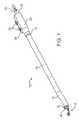
- FIG. 1shows a perspective view of an endoscope with an imaging assembly according to one embodiment of the present invention.
- FIG. 2shows a perspective view of the distal end of an insertion tube of the endoscope of FIG. 1 with a polarizer cap.
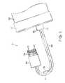
- FIG. 3shows a perspective back view of the polarizer cap of FIG. 2 .
- FIG. 4shows a perspective view of the imaging assembly shown in FIG. 1 .
- FIG. 5shows a perspective view of the distal ends of the endoscope and imaging assembly of FIG. 1 with a cross-sectional view of the lens barrel of the imaging assembly.
- FIG. 6shows a cross-sectional view of a peritoneal cavity with multiple endoscopes.
- FIG. 1illustrates a first exemplary endoscope 10 of the present invention.
- This endoscope 10can be used in a variety of medical procedures in which imaging of a body tissue, organ, cavity or lumen is required.
- the types of proceduresinclude, for example, anoscopy, arthroscopy, bronchoscopy, colonoscopy, cystoscopy, EGD, laparoscopy, and sigmoidoscopy.
- the endoscope 10 of FIG. 1includes an insertion tube 12 and an imaging assembly 14 , a section of which is housed inside the insertion tube 12 .
- the insertion tube 12has two longitudinal channels 16 .
- the insertion tube 12may have any number of longitudinal channels.
- An instrumentcan reach the body cavity to perform any desired procedures, such as to take samples of suspicious tissues or to perform other surgical procedures such as polypectomy.
- the instrumentsmay be, for example, a retractable needle for drug injection, hydraulically actuated scissors, clamps, grasping tools, electrocoagulation systems, ultrasound transducers, electrical sensors, heating elements, laser mechanisms and other ablation means.
- one of the channelscan be used to supply a washing liquid such as water for washing.
- Another or the same channelmay be used to supply a gas, such as CO 2 or air into the organ.
- the channels 16may also be used to extract fluids or inject fluids, such as a drug in a liquid carrier, into the body.
- Various biopsy, drug delivery, and other diagnostic and therapeutic devicesmay also be inserted via the channels 16 to perform specific functions.
- the insertion tube 12preferably is steerable or has a steerable distal end region 18 as shown in FIG. 1 .
- the length of the distal end region 18may be any suitable fraction of the length of the insertion tube 12 , such as one half, one third, one fourth, one sixth, one tenth, or one twentieth.
- the insertion tube 12may have control cables (not shown) for the manipulation of the insertion tube 12 .
- the control cablesare symmetrically positioned within the insertion tube 12 and extend along the length of the insertion tube 12 .
- the control cablesmay be anchored at or near the distal end 36 of the insertion tube 12 .
- Each of the control cablesmay be a Bowden cable, which includes a wire contained in a flexible overlying hollow tube.
- the wires of the Bowden cablesare attached to controls 20 in the handle 22 . Using the controls 20 , the wires can be pulled to bend the distal end region 18 of the insertion tube 12 in a given direction.
- the Bowden cablescan be used to articulate the distal end region 18 of the insertion tube 12 in different directions.
- the endoscope 10may include a control handle 22 connected to the proximal end 24 of the insertion tube 12 .
- the control handle 22has one or more ports and/or valves (not shown) for controlling access to the channels 16 of the insertion tube 12 .
- the ports and/or valvescan be air or water valves, suction valves, instrumentation ports, and suction/instrumentation ports.
- the control handle 22may additionally include buttons 26 for taking pictures with an imaging device on the insertion tube 12 , the imaging assembly 14 , or both.
- the proximal end 28 of the control handle 22may include an accessory outlet 30 ( FIG. 1 ) that provides fluid communication between the air, water and suction channels and the pumps and related accessories.
- the same outlet 30 or a different outletcan be used for electrical lines to light and imaging components at the distal end of the endoscope 10 .
- the endoscope 10also includes a main imaging device 32 and main light sources 34 , both of which are disposed at the distal end 36 of the insertion tube 12 , and a polarizer cap 38 that is adapted to be mounted on the distal end 36 of the insertion tube 12 to cover the main imaging device 32 and main light sources 34 .
- FIG. 2shows the polarizer cap 38 removed from the distal end 36 of the insertion tube 12
- FIG. 5shows the polarizer cap 38 mounted on the distal end 36 of the insertion tube 12 .
- the main imaging device 32 at the distal end 36 of the insertion tube 12may include, for example, a lens, single chip sensor, multiple chip sensor or fiber optic implemented devices.
- the main imaging device 32in electrical communication with a processor and/or monitor, may provide still images or recorded or live video images.
- the light sources 34may be light emitting diodes (LEDs) or fiber optical delivery of light from an external light source.
- the light sources 34preferably are equidistant from the main imaging device 32 to provide even illumination. The intensity of each light source 34 can be adjusted to achieve optimum imaging.
- the circuits for the main imaging device 32 and light sources 34may be incorporated into a printed circuit board (PCB).
- the insertion tube 12has a channel 40 for supplying a liquid such as water for cleaning the lenses of the main imaging device 32 and the light sources 34 .
- the polarizer cap 38includes a cylindrical sidewall 42 , an end wall 44 , and polarizing filters 46 , 48 mounted on the end wall 44 .
- the cylindrical sidewall 42 and end wall 44may form an integral part that is made by injection molding of a suitable biocompatible material such as medical grade plastics.
- the end wall 44preferably has an opening 50 for accommodating the polarizing filter 46 for the main imaging device 32 .
- the opening 50may have any arrangement suitable for retaining the polarizing filter 46 .
- the opening 50may have a recessed lip for receiving the polarizing filter 46 .
- the polarizing filter 46can be placed in the recessed lip and fixed there by adhesive bonding or by a mechanical snap fit.
- the end wall 44preferably has an opening 52 for accommodating the polarizing filter 48 for each of the light sources 34 .
- the opening 52may have any arrangement suitable for retaining the polarizing filter 48 .
- One example of such suitable arrangementis the recessed lip described above.
- the end wall 44preferably has an opening 54 for each of the instrument channels 16 so that the cap 38 does not block the channels 16 .
- the end wall 44may further include an opening 56 for the channel 40 for supplying a liquid to clean the lenses of the imaging device 32 and the light sources 34 .
- the cap 38has one or more features that allow liquid from the channel 40 to reach over the cap 38 to clean the exterior surfaces of polarizing filters 46 , 48 .
- the end wall 44 of the cap 38may be sufficiently thin to allow the liquid from the channel 40 to reach over the cap 38 to clean the exterior surfaces of polarizing filters 46 , 48 .
- the cap 38may have variable thickness and/or angled features that allow liquid from the channel 40 to reach the polarizing filters 46 , 48 .
- the cap 38may have a ramp, plate or channel that allows liquid from the channel 40 to reach the polarizing filters 46 , 48 .
- the locations, configurations and sizes of the openings 50 , 52 , 54 , 56preferably correspond to the locations, configurations and sizes of the main imaging device 32 , light sources 34 , channels 16 , and clean liquid channel 40 , respectively.
- the cap 38preferably has a ring 58 located around the inner perimeter of the cap 38 .
- the ring 58helps secure the cap 38 to the distal end region of the insertion tube 12 .
- the ring 58is made from a compressive material such as silicon.
- the ring 58can be made from other compressive materials, such as compressive rubbers, polymers and/or foams.
- the ring 58may be attached the inner perimeter of the cap 38 by any suitable means such as adhesive bonding, mechanical over molding, or plastic snap features.
- the inside diameter of the ring 58preferably is slightly smaller than the outer diameter of the insertion tube 12 so that the ring 58 can apply a compressive force to the outer surface of the insertion tube 12 .
- This compressive forcepreferably is sufficient to create the necessary friction force to ensure that the cap 38 remains in the same position and orientation during a medical procedure, yet to allow the cap 38 to be slide on and off of the insertion tube 12 without difficulty.
- the cap 38may have any other type of arrangement for attachment to the insertion tube 12 .
- the cap 38may have clasps which snap on to the insertion tube 12 .
- the attachmentmay be similar to the way in which a suction cap for endoscopic mucosal resection is attached to a colonoscope, as is well known in the art.
- polarizing filterand “polarizer” as used in this specification refer to any device that blocks one or more components of light while allowing one or more other components to pass through.
- polarizing filtersmay be made from a material that blocks light waves traveling in all planes from passing through the filter except for light waves propagating in one specific plane of orientation, often referred to as the plane of polarization or the plane of transmission.
- Polarizing filtersmay be constructed using various techniques that use light absorption, reflection, scattering or birefringence to block light from passing through the filter that is not orientated parallel with the plane of transmission.
- the amount of light that passes through the two polarizing filtersis proportional to the relative angle of orientation of the two filters. This is because when the polarization plane of the two filters is at the same angle of orientation, the majority of light waves in the plane of transmission will pass through both filters. As one of the filters is rotated, light that is polarized by the first filter is then attenuated or blocked by the second filter. The maximum amount of light reduction or extinction occurs when the polarizing planes of the two filters are orientated at 90° relative to each other. It is common to find polarizing filters that when orientated at 90° provide 99% or greater extinction of light transmission.
- Light reduction or extinction by way of a combination of two polarizing filterscan similarly be achieved using circular polarizing filters, such as a combination of a left-hand polarizing filter and a right-hand polarizing filter (i.e., a combination of a polarizing filter that rotates the light clockwise and a polarizing filter that rotates the light counter-clockwise).
- circular polarizing filterssuch as a combination of a left-hand polarizing filter and a right-hand polarizing filter (i.e., a combination of a polarizing filter that rotates the light clockwise and a polarizing filter that rotates the light counter-clockwise).
- a circular polarizing filterconverts unpolarized light to circularly polarized light. Just as a linear polarizing filter transmits light only in one plane of polarization, a circular polarizer transmits light in only one particular circular orientation of polarization.
- a circular polarizing filteroften has a composite structure that includes a linear polarizing filter and a quarter wave retarder. The retarder axis is oriented at 45° with respect to the axis of the linear polarizing filter. As incident light passes through the composite it is converted to circularly polarized light.
- first right-hand circular polarizing filterwhich, for instance, is constructed as a linear polarizing filter followed by a quarter wave retarder orientated at 45° with respect to the axis of the linear polarizing filter
- second left-hand circular polarizing filterwhich, for instance, is constructed as a quarter wave retarder followed by a linear polarizing filter with the retarder oriented at ⁇ 45° with respect to the axis of the linear polarizing filter
- the imaging assembly 14may include a tubular body 60 , a handle 62 connected to the proximal end 61 of the tubular body 60 , an auxiliary imaging device 64 , a link 66 that provides physical and/or electrical connection between the auxiliary imaging device 64 to the distal end 68 of the tubular body 60 , and an auxiliary light source 70 ( FIG. 5 ).
- the imaging assembly 14is used to provide an auxiliary imaging device at the distal end of the endoscope 10 .
- the imaging assembly 14is placed inside one of the channels 16 of the endoscope's insertion tube 12 with its auxiliary imaging device 64 disposed beyond the distal end 36 of the insertion tube 12 . This can be accomplished by first inserting the distal end of the imaging assembly 14 into the insertion tube's channel 16 from the endoscope's handle 18 and then pushing the imaging assembly 14 further into the assembly 14 until the auxiliary imaging device 64 and link 66 of the imaging assembly 14 are positioned outside the distal end 36 of the insertion tube 12 as shown in FIG. 5 .
- the auxiliary imaging device 64may include a lens barrel 72 having one or more lenses 74 , an imaging sensor, and a printed circuit board (PCB).
- the imaging sensormay be an electronic device which converts light incident on photosensitive semiconductor elements into electrical signals.
- the imaging sensormay detect either color or black-and-white images.
- the signals from the imaging sensorcan be digitized and used to reproduce an image that is incident on the imaging sensor.
- Two commonly used types of image sensorsare Charge Coupled Devices (CCD) such as a VCC-5774 produced by Sanyo of Osaka, Japan and Complementary Metal Oxide Semiconductor (CMOS) camera chips such as an OVT 6910 produced by OmniVision of Sunnyvale, Calif.
- CCDCharge Coupled Devices
- CMOSComplementary Metal Oxide Semiconductor
- the endoscope 10preferably includes a polarizing filter 76 placed in front of the auxiliary imaging device 64 .
- the polarizing filter 76may be placed inside the lens barrel 72 .
- the polarizing filter 76may be placed directly onto the image sensor itself, or incorporated at various other locations in the lens barrel 72 such as at the end closest to the imaging sensor, or even between the lenses 74 .
- the polarizing filter 76may be simply placed in front of the auxiliary imaging device.
- the auxiliary imaging device 64 of the imaging assembly 14preferably faces backwards towards the main imaging device 32 as illustrated in FIG. 3 .
- the auxiliary imaging device 64may be oriented so that the auxiliary imaging device 64 and the main imaging device 32 have adjacent or overlapping viewing areas.
- the auxiliary imaging device 64may be oriented so that the auxiliary imaging device 64 and the main imaging device 32 simultaneously provide different views of the same area.
- the auxiliary imaging device 64provides a retrograde view of the area, while the main imaging device 32 provides a front view of the area.
- the auxiliary imaging device 64could be oriented in other directions to provide other views, including views that are substantially parallel to the axis of the main imaging device 32 .
- the link 66connects the auxiliary imaging device 64 to the distal end 68 of the tubular body 60 .
- the link 66is a flexible link that is at least partially made from a flexible shape memory material that substantially tends to return to its original shape after deformation.
- Shape memory materialsare well known and include shape memory alloys and shape memory polymers.
- a suitable flexible shape memory materialis a shape memory alloy such as nitinol.
- the flexible link 66resumes its natural bent configuration as shown in FIG. 3 .
- the natural configuration of the flexible link 66is the configuration of the flexible link 66 when the flexible link 66 is not subject to any force or stress.
- the auxiliary imaging device 64faces substantially back towards the distal end 36 of the insertion tube 12 as shown in FIG. 5 .
- the auxiliary light source 70(as well as other components) of the imaging assembly 14 is placed on the flexible link 66 , in particular on the curved concave portion of the flexible link 66 .
- the auxiliary light source 70provides illumination for the auxiliary imaging device 64 and may face substantially the same direction as the auxiliary imaging device 64 as shown in FIG. 5 .
- the endoscope 10includes another polarizing filter 78 placed in front of the auxiliary light source 70 .
- the polarizing filter 78may be attached to the auxiliary light source 70 by any suitable means such as adhesive bonding or welding.
- the flexible link 66may be encapsulated or shrouded by flexible tubing, heat-shrinkable tubing, urethanes, rubber or silicon so as to allow smooth profile transition from the tubular body 60 to the imaging device 64 .
- This encapsulationmay be translucent to allow light from the light source 70 to project through the encapsulation, or the encapsulation may include a window section around the light source 70 .
- the main imaging device 32 and its light source 34face the auxiliary imaging device 64 and its light source 70 , the light sources 34 , 45 of the imaging devices 32 , 64 may interfere with the opposing imaging device 64 , 32 . That is, the main light source 34 may shine directly into auxiliary imaging device 64 and the auxiliary light source 70 may shine directly into the main imaging device 32 , degrading both images.
- the polarization plane of the polarizing filter 46 for the main imaging device 32may be set at a substantially 90° angle from the polarization plane of the polarizing filter 78 for the auxiliary light source 70 .
- the light, which is emitted from the auxiliary light source 70 and passes though the polarizing filter 78may be filtered out by the polarizing filter 46 and may not reach the main imaging device 32 .
- the polarization plane of the polarizing filter 76 for the auxiliary imaging device 64may be set at a substantially 90° angle from the polarization plane of the polarizing filters 48 for the main light sources 34 . With this arrangement, the light, which is emitted from the main light sources 34 and passes though the polarizing filters 48 , may be filtered out by the polarizing filter 76 and may not reach the auxiliary imaging device 64 .
- the polarization plane of the polarizing filter 46 for the main imaging device 32may be substantially aligned with the polarization plane of the polarizing filters 48 for the main light sources 34 so that the light, which is emitted from the main light sources 34 and passes though the polarizing filters 48 , may pass through the polarizing filter 46 and may be received by the main imaging device 32 .
- the polarization plane of the polarizing filter 76 for the auxiliary imaging device 64may be substantially aligned with the polarization plane of the polarizing filter 78 for the auxiliary light source 70 so that the light, which is emitted from the auxiliary light source 70 and passes though the polarizing filter 78 , may pass through the polarizing filter 76 and may be received by the auxiliary imaging device 64 .
- the desired relative orientations of the polarizing filters' the polarization planesmay be achieved in any suitable manner.
- the polarization planes of the polarizing filters 46 , 48 for the main imaging device 32 and main light sources 34may be aligned and fixed in the polarizer cap 38
- the polarization planes of the polarizing filters 76 , 78 for the auxiliary imaging device 64 and auxiliary light source 70may be aligned and fixed in the imaging assembly 14 .
- the imaging assembly 14may be rotated within the channel 16 of the insertion tube 12 by means of its handle 62 until the polarization planes of the polarizing filters 76 , 78 in the imaging assembly 14 are at a substantially 90° angle from the polarization planes of the polarizing filters 46 , 48 in the polarizer cap 38 .
- the orientations of the polarizing filters' the polarization planesmay be determined and set during attachment by viewing a light with a known polarization passing through polarizing filters.
- the polarizing filtersmay have asymmetrical shapes or other locating features so that the orientations of their polarization planes may be readily determined.
- the polarizing filters 46 , 48 , 76 and 78are described above as linear polarizing filters, all or some of them may be circular polarizing filters.
- the polarizing filter 76 for the auxiliary imaging device 64may be a circular polarizing filter of one orientation (such as the left hand), and the polarizing filters 48 for the main light sources 34 may be a circular polarizing filter of the opposite orientation (such as the right hand).
- the retarders of the opposite polarizing filters 48 and 76face each other.
- the polarizing filter 46 for the main imaging device 32may be a circular polarizing filter of one orientation
- the polarizing filter 78 for the auxiliary light source 70may be a circular polarizing filter of the opposite orientation.
- the retarders of the opposite polarizing filters 46 and 78face each other. In these configurations, the light from a light source is blocked from the image device facing the light source.
- the use of circular polarizing filters in this configurationallows significant light reduction from glare caused by the light sources without requiring a precise angular alignment or orientation between the two polarizing filters.
- the auxiliary imaging device 64 and its light source 70may be connected to a control box (not shown) via electrical conductors that extend from the imaging device 64 and light source 70 ; through the link 66 , tubular body 60 , and handle 62 ; to the control box.
- the electrical conductorsmay carry power and control commands to the auxiliary imaging device 64 and its light source 70 and image signals from the auxiliary imaging device 64 to the control box.
- the control boxincludes at least an image and signal processing device and a housing in which the image and signal processing device is disposed, although the control box can be configured in any suitable manner.
- the housingmay include a control panel and connectors.
- the control panelincludes buttons and knobs for controlling the functionalities of the control box.
- the image and signal processing devicemay include one or more integrated circuits and memory devices along with associated discrete components.
- the deviceallows image signals from the imaging devices 32 , 64 to be processed for the enhancement of image quality, extraction of still images from the image signals, and conversion of video format for compatibility with the display device.
- the control boxpreferably processes the video image signal from the auxiliary imaging device 64 and transmits it to a display device such as a television or a monitor such as a liquid crystal display monitor. Still images can be captured from the video image signal. The video image or still image may be displayed on the display device.
- the display devicemay also include textual data that are used to display information such as patient information, reference numbers, date, and/or time.
- the image signal from the main imaging device 32may also be processed by the control box in the same way that the image signal from the auxiliary imaging device 64 is processed.
- the images from the main and auxiliary imaging devices 32 , 64may be displayed on two separate monitors or on the same monitor with a split screen.
- the control boxmay further be used to adjust the parameters of the imaging devices 32 , 64 and their light sources 34 , 70 , such as brightness, exposure time and mode settings.
- the adjustmentcan be done by writing digital commands to specific registers controlling the parameters.
- the registerscan be addressed by their unique addresses, and digital commands can be read from and written to the registers to change the various parameters.
- the control boxcan change the register values by transmitting data commands to the registers.
- the control boxmay additionally be used as an interface to the patient records database.
- EMRpatient electronic medical records
- the signal processing circuitcan convert image and video data to a format suitable for filing in the patient EMR file such as images in .jpeg, tif, or .bmp format among others.
- the processed signalcan be transmitted to the medical professional's computer or the medical facilities server via a cable or dedicated wireless link.
- a switch on the control panelcan be used to enable this transmission.
- the datacan be stored with a unique identification for the patient in electronic memory provided in the control box itself.
- the signal processing circuitcan be utilized to convert the video and image data to be compatible with the electronic medical records system used by the medical professional.
- the processingmay include compression of the data.
- a cable or a wireless linkmay be used to transmit the data to a computer.
- a technicianmay first install the polarizer cap 38 onto the endoscope's insertion tube 12 .
- a physicianmay then insert the endoscope into a body cavity through an orifice of the body.
- the physicianmay decide to use the imaging assembly 14 in order to obtain a rear-viewing image of a certain tissue.
- the physicianmay straighten the flexible link 66 of the imaging assembly 14 and insert the straightened distal end of the imaging assembly 14 into the channel 16 of the endoscope's insertion tube 12 from the handle 22 .
- the imaging assembly 14can then be pushed towards the distal end 36 of the insertion tube 12 .
- the flexible link 66resumes its natural bent configuration as shown in FIG. 2 .
- the main imaging device 32now captures a front-viewing image, and the auxiliary imaging device 64 simultaneously captures a rear-viewing image of the same area.
- the physicianmay then rotate the imaging assembly 14 so that the polarization planes of the polarizing filters 76 , 78 in the imaging assembly 14 are at a substantially 90° angle from the polarization planes of the polarizing filters 46 , 48 in the polarizer cap 38 .
- the physicianlocks or fixes the orientation of the imaging assembly 14 relative to the insertion tube 12 . The physician then continues with the procedure.
- polarizing filtersare placed over only the auxiliary imaging device 64 of the imaging assembly 14 and the main light sources 34 to reduce light interference between them.
- a low intensity auxiliary light source 70may be used for the auxiliary imaging device 64 to alleviate any bright spots that could be seen by the main imaging device 32 .
- This arrangementallows maximum light intake by the main imaging device 32 without light loss caused by a polarizing filter.
- polarizing filtersare placed over only the main imaging device 32 and the auxiliary imaging device 64 .
- imaging sensors used in the endoscopespecifically their light sensitivities, resistance to blooming, and dynamic ranges, as well as depending on the types of light sources used in the endoscope and their illumination intensities and/or wave length spectrums.
- the main imaging device 32 and main light sources 34may share a polarizing filter.
- the polarizer cap mounted on the distal end of the insertion tubemay have a large polarizing filter approximately the size of the cap' end wall. This large filter may have openings for the channels 16 of the insertion tube 12 .
- the filtermay occupy only the area of the cap's end wall in front of the main imaging device 32 and main light sources 34 . This embodiment allows for the orientation of the polarization plane in front of the main imaging device 32 and main light sources 34 to be precisely orientated.
- a polarizing filtermay be placed in a cap mounted in front of an imaging device, placed in the lens assembly of the imaging device, or attached to the front of the imaging device.
- Various techniques for attachmentmay be used, such as ring and clamp arrangements, snap fit or plastic friction fit arrangements, or even permanent bonding.
- polarizing filtersmay be placed along the optical path of the fiber optic bundles that run along the length of the endoscope, or even placed in an external light source box.
- a cap with one or more polarizing filterssimilar to the cap 38 shown in FIGS. 2 and 3 , may be placed on the auxiliary imaging device 64 .
- a polarizer cap 84 , 86may be placed over one or more of the endoscopes 80 , 82 to reduce light interference caused by endoscopes 80 , 82 .
- the endoscopes 80 , 82are inserted into a peritoneal cavity 88 .
- at least one of the endoscopes 80 , 82has a channel that allows a surgical tool 90 to access the peritoneal cavity 88 .
- one or more of the endoscopes 80 , 82may have a light source. In some cases, each and every one of the endoscopes 80 , 82 has a light source. Similarly, one or more of the endoscopes 80 , 82 may have an imaging device. In some cases, each and every one of the endoscopes 80 , 82 has an imaging device. In one particular case, only one of the endoscopes has a light source, while each of the other endoscopes has only an imaging device. In the illustrated embodiment, the polarizing filters of the same cap 84 , 86 may have the same plane of polarization, and the polarizing filters of the different caps 84 , 86 may have different planes of polarization.
- the capsmay have the same plane of polarization but a physician can rotate one or more endoscopes to the appropriate orientations. If only two endoscopes 80 , 82 are used, the two caps 84 , 86 may have their planes of polarization orientated at 90° from one another. If only three endoscopes are used, the three caps may have polarization planes orientated at 120° relative to one another so as to provide a significant cancellation of light interference at each endoscope.
- the endoscopemay have orientation arrangements on both the polarizer cap and the imaging assembly such that the orientation between polarizing filters may be easily adjusted.
- One such embodimentincludes a small magnet that is permanently fixed to the polarizer cap, and a metallic element fixed to the imaging assembly.
- the magnetmay be a rare earth magnet such as a Neodymium Iron Boron type permanent magnet.
- the orientation of the magnet and metallic elementis designed such that the magnetic field generated by the magnet will attract the metallic element most strongly when the polarizing filters are properly aligned. In this manner, when the metallic element is in close proximity to the magnet, it will naturally be pulled by the magnet into the correct position.
- the magnet and metallic elementcome into contact, an attachment is formed which resists change of orientation and maintains the proper orientation between the polarizing filters. Only when a substantial force is applied, such as when the physician forcefully advancing the imaging assembly, will the magnetic attachment be broken, allowing the physician to re-align or remove the imaging assembly.
- the magnetmay be placed in the imaging assembly and a metallic element may be located on the cap.
- magnetsmay be used on both the imaging assembly and the cap.
- the orientation featuresinclude a feature, such as a pin, rod or geometric feature, affixed to and protruding slightly away from the imaging assembly, and a feature, such as a cup and tube, on the polarizer cap that mates with the corresponding feature on the imaging assembly.
- the featuresmay be made from a compressive material such as rubber so that when the two features are engaged a substantial force is needed to break the engagement.
- the physicianwould first slide the imaging assembly past the distal end of the insertion tube and then, under the guidance of the auxiliary imaging device, rotate the imaging assembly to achieve the correct relative orientation between the polarizing filters.
- the physicianmay retract the imaging assembly so that the two features engage and lock together. To later disengage the features, the physician may forcefully advance the imaging assembly.
- the distal end of the imaging assemblyincludes a mechanism that can fix the position of the imaging assembly in the channel of the insertion tube.
- a mechanismmay include the use of inflatable balloons, springs that are actuated via guide-wires, mechanical engagement arrangements, or frictional methods such as large diameter compressive regions incorporating rubber or foam.
- insertion tubeIn the present application, the terms “insertion tube,” “imaging assembly” and “endoscope” are interchangeable, may have the same or similar meanings, and may have the same or similar features and functions. Different terms are used in the application for ease of identification and description. Additionally, such a description should not be used to limit the breadth of the application.
- insertion tubeimaging assembly
- endoscopemerely refers to possible types of instruments in the broad field of endoscopy and the invention may be applied to many forms of endoscopes and medical imaging devices.
- the configuration of one endoscope that is inserted through the channel of another endoscopecan be referred to as a major-minor endoscope configuration, where the larger diameter endoscope is referred to as the major endoscope and the smaller diameter endoscope as the minor endoscope.
Landscapes
- Health & Medical Sciences (AREA)
- Life Sciences & Earth Sciences (AREA)
- Surgery (AREA)
- Nuclear Medicine, Radiotherapy & Molecular Imaging (AREA)
- Biomedical Technology (AREA)
- Optics & Photonics (AREA)
- Pathology (AREA)
- Radiology & Medical Imaging (AREA)
- Biophysics (AREA)
- Engineering & Computer Science (AREA)
- Physics & Mathematics (AREA)
- Heart & Thoracic Surgery (AREA)
- Medical Informatics (AREA)
- Molecular Biology (AREA)
- Animal Behavior & Ethology (AREA)
- General Health & Medical Sciences (AREA)
- Public Health (AREA)
- Veterinary Medicine (AREA)
- Endoscopes (AREA)
Abstract
Description
Claims (11)
Priority Applications (3)
| Application Number | Priority Date | Filing Date | Title |
|---|---|---|---|
| US11/938,256US8797392B2 (en) | 2005-01-05 | 2007-11-10 | Endoscope assembly with a polarizing filter |
| PCT/US2008/083034WO2009062179A1 (en) | 2007-11-10 | 2008-11-10 | Endoscope assembly with a polarizing filter |
| US14/338,247US20140336459A1 (en) | 2005-01-05 | 2014-07-22 | Endoscope assembly with a polarizing filter |
Applications Claiming Priority (8)
| Application Number | Priority Date | Filing Date | Title |
|---|---|---|---|
| US3055905A | 2005-01-05 | 2005-01-05 | |
| US11/215,660US20060149129A1 (en) | 2005-01-05 | 2005-08-29 | Catheter with multiple visual elements |
| US77244206P | 2006-02-09 | 2006-02-09 | |
| US11/609,838US8182422B2 (en) | 2005-12-13 | 2006-12-12 | Endoscope having detachable imaging device and method of using |
| US11/626,189US8235887B2 (en) | 2006-01-23 | 2007-01-23 | Endoscope assembly with retroscope |
| US11/672,020US8289381B2 (en) | 2005-01-05 | 2007-02-06 | Endoscope with an imaging catheter assembly and method of configuring an endoscope |
| US11/673,470US8872906B2 (en) | 2005-01-05 | 2007-02-09 | Endoscope assembly with a polarizing filter |
| US11/938,256US8797392B2 (en) | 2005-01-05 | 2007-11-10 | Endoscope assembly with a polarizing filter |
Related Parent Applications (1)
| Application Number | Title | Priority Date | Filing Date |
|---|---|---|---|
| US11/673,470Continuation-In-PartUS8872906B2 (en) | 2005-01-05 | 2007-02-09 | Endoscope assembly with a polarizing filter |
Related Child Applications (1)
| Application Number | Title | Priority Date | Filing Date |
|---|---|---|---|
| US14/338,247ContinuationUS20140336459A1 (en) | 2005-01-05 | 2014-07-22 | Endoscope assembly with a polarizing filter |
Publications (2)
| Publication Number | Publication Date |
|---|---|
| US20080130108A1 US20080130108A1 (en) | 2008-06-05 |
| US8797392B2true US8797392B2 (en) | 2014-08-05 |
Family
ID=40383913
Family Applications (2)
| Application Number | Title | Priority Date | Filing Date |
|---|---|---|---|
| US11/938,256Active - Reinstated2028-04-10US8797392B2 (en) | 2005-01-05 | 2007-11-10 | Endoscope assembly with a polarizing filter |
| US14/338,247AbandonedUS20140336459A1 (en) | 2005-01-05 | 2014-07-22 | Endoscope assembly with a polarizing filter |
Family Applications After (1)
| Application Number | Title | Priority Date | Filing Date |
|---|---|---|---|
| US14/338,247AbandonedUS20140336459A1 (en) | 2005-01-05 | 2014-07-22 | Endoscope assembly with a polarizing filter |
Country Status (2)
| Country | Link |
|---|---|
| US (2) | US8797392B2 (en) |
| WO (1) | WO2009062179A1 (en) |
Cited By (32)
| Publication number | Priority date | Publication date | Assignee | Title |
|---|---|---|---|---|
| US9044185B2 (en) | 2007-04-10 | 2015-06-02 | Avantis Medical Systems, Inc. | Method and device for examining or imaging an interior surface of a cavity |
| US20160143519A1 (en)* | 2014-11-20 | 2016-05-26 | Globalmedia Group, Llc | Polarizing endoscopy system and method |
| US9474440B2 (en) | 2009-06-18 | 2016-10-25 | Endochoice, Inc. | Endoscope tip position visual indicator and heat management system |
| US9667935B2 (en) | 2013-05-07 | 2017-05-30 | Endochoice, Inc. | White balance enclosure for use with a multi-viewing elements endoscope |
| US9706908B2 (en) | 2010-10-28 | 2017-07-18 | Endochoice, Inc. | Image capture and video processing systems and methods for multiple viewing element endoscopes |
| US9943218B2 (en) | 2013-10-01 | 2018-04-17 | Endochoice, Inc. | Endoscope having a supply cable attached thereto |
| US9949623B2 (en) | 2013-05-17 | 2018-04-24 | Endochoice, Inc. | Endoscope control unit with braking system |
| US9968242B2 (en) | 2013-12-18 | 2018-05-15 | Endochoice, Inc. | Suction control unit for an endoscope having two working channels |
| US10045685B2 (en) | 2006-01-23 | 2018-08-14 | Avantis Medical Systems, Inc. | Endoscope |
| US10064541B2 (en) | 2013-08-12 | 2018-09-04 | Endochoice, Inc. | Endoscope connector cover detection and warning system |
| US10078207B2 (en) | 2015-03-18 | 2018-09-18 | Endochoice, Inc. | Systems and methods for image magnification using relative movement between an image sensor and a lens assembly |
| US10105039B2 (en) | 2013-06-28 | 2018-10-23 | Endochoice, Inc. | Multi-jet distributor for an endoscope |
| US10123684B2 (en) | 2014-12-18 | 2018-11-13 | Endochoice, Inc. | System and method for processing video images generated by a multiple viewing elements endoscope |
| US10130246B2 (en) | 2009-06-18 | 2018-11-20 | Endochoice, Inc. | Systems and methods for regulating temperature and illumination intensity at the distal tip of an endoscope |
| US10258222B2 (en) | 2014-07-21 | 2019-04-16 | Endochoice, Inc. | Multi-focal, multi-camera endoscope systems |
| US10271713B2 (en) | 2015-01-05 | 2019-04-30 | Endochoice, Inc. | Tubed manifold of a multiple viewing elements endoscope |
| US10292570B2 (en) | 2016-03-14 | 2019-05-21 | Endochoice, Inc. | System and method for guiding and tracking a region of interest using an endoscope |
| US10376181B2 (en) | 2015-02-17 | 2019-08-13 | Endochoice, Inc. | System for detecting the location of an endoscopic device during a medical procedure |
| US10401611B2 (en) | 2015-04-27 | 2019-09-03 | Endochoice, Inc. | Endoscope with integrated measurement of distance to objects of interest |
| US10488648B2 (en) | 2016-02-24 | 2019-11-26 | Endochoice, Inc. | Circuit board assembly for a multiple viewing element endoscope using CMOS sensors |
| US10516865B2 (en) | 2015-05-17 | 2019-12-24 | Endochoice, Inc. | Endoscopic image enhancement using contrast limited adaptive histogram equalization (CLAHE) implemented in a processor |
| US10517464B2 (en) | 2011-02-07 | 2019-12-31 | Endochoice, Inc. | Multi-element cover for a multi-camera endoscope |
| US10524645B2 (en) | 2009-06-18 | 2020-01-07 | Endochoice, Inc. | Method and system for eliminating image motion blur in a multiple viewing elements endoscope |
| US10542877B2 (en) | 2014-08-29 | 2020-01-28 | Endochoice, Inc. | Systems and methods for varying stiffness of an endoscopic insertion tube |
| US10595714B2 (en) | 2013-03-28 | 2020-03-24 | Endochoice, Inc. | Multi-jet controller for an endoscope |
| US10663714B2 (en) | 2010-10-28 | 2020-05-26 | Endochoice, Inc. | Optical system for an endoscope |
| US10898062B2 (en) | 2015-11-24 | 2021-01-26 | Endochoice, Inc. | Disposable air/water and suction valves for an endoscope |
| US10993605B2 (en) | 2016-06-21 | 2021-05-04 | Endochoice, Inc. | Endoscope system with multiple connection interfaces to interface with different video data signal sources |
| US11082598B2 (en) | 2014-01-22 | 2021-08-03 | Endochoice, Inc. | Image capture and video processing systems and methods for multiple viewing element endoscopes |
| US11234581B2 (en) | 2014-05-02 | 2022-02-01 | Endochoice, Inc. | Elevator for directing medical tool |
| US11529197B2 (en) | 2015-10-28 | 2022-12-20 | Endochoice, Inc. | Device and method for tracking the position of an endoscope within a patient's body |
| US12207796B2 (en) | 2013-03-28 | 2025-01-28 | Endochoice Inc. | Multi-jet controller for an endoscope |
Families Citing this family (57)
| Publication number | Priority date | Publication date | Assignee | Title |
|---|---|---|---|---|
| US20080275298A1 (en)* | 2004-10-11 | 2008-11-06 | Novation Science, Llc | Dual View Endoscope |
| US20070293720A1 (en)* | 2005-01-05 | 2007-12-20 | Avantis Medical Systems, Inc. | Endoscope assembly and method of viewing an area inside a cavity |
| US20080021274A1 (en)* | 2005-01-05 | 2008-01-24 | Avantis Medical Systems, Inc. | Endoscopic medical device with locking mechanism and method |
| US8182422B2 (en) | 2005-12-13 | 2012-05-22 | Avantis Medical Systems, Inc. | Endoscope having detachable imaging device and method of using |
| US8289381B2 (en) | 2005-01-05 | 2012-10-16 | Avantis Medical Systems, Inc. | Endoscope with an imaging catheter assembly and method of configuring an endoscope |
| US8797392B2 (en) | 2005-01-05 | 2014-08-05 | Avantis Medical Sytems, Inc. | Endoscope assembly with a polarizing filter |
| US8872906B2 (en) | 2005-01-05 | 2014-10-28 | Avantis Medical Systems, Inc. | Endoscope assembly with a polarizing filter |
| US8287446B2 (en) | 2006-04-18 | 2012-10-16 | Avantis Medical Systems, Inc. | Vibratory device, endoscope having such a device, method for configuring an endoscope, and method of reducing looping of an endoscope |
| EP2023795A2 (en) | 2006-05-19 | 2009-02-18 | Avantis Medical Systems, Inc. | Device and method for reducing effects of video artifacts |
| CN102215732A (en)* | 2008-08-01 | 2011-10-12 | 国际科学技术医疗系统有限责任公司 | High resolution digital video colposcope with built-in polarized led illumination and computerized clinical data management system |
| RU2011121349A (en)* | 2008-10-27 | 2012-12-10 | Конинклейке Филипс Электроникс Н.В. | DEVICE AND METHOD FOR OPTICAL RESEARCH OF THE INTERNAL VOLUME OF THE PART OF THE ORGANISM |
| US20110009694A1 (en)* | 2009-07-10 | 2011-01-13 | Schultz Eric E | Hand-held minimally dimensioned diagnostic device having integrated distal end visualization |
| US9101268B2 (en) | 2009-06-18 | 2015-08-11 | Endochoice Innovation Center Ltd. | Multi-camera endoscope |
| WO2010146587A1 (en) | 2009-06-18 | 2010-12-23 | Peer Medical Ltd. | Multi-camera endoscope |
| US9642513B2 (en) | 2009-06-18 | 2017-05-09 | Endochoice Inc. | Compact multi-viewing element endoscope system |
| US9901244B2 (en) | 2009-06-18 | 2018-02-27 | Endochoice, Inc. | Circuit board assembly of a multiple viewing elements endoscope |
| US9713417B2 (en) | 2009-06-18 | 2017-07-25 | Endochoice, Inc. | Image capture assembly for use in a multi-viewing elements endoscope |
| US9101287B2 (en) | 2011-03-07 | 2015-08-11 | Endochoice Innovation Center Ltd. | Multi camera endoscope assembly having multiple working channels |
| US9706903B2 (en) | 2009-06-18 | 2017-07-18 | Endochoice, Inc. | Multiple viewing elements endoscope system with modular imaging units |
| US8926502B2 (en) | 2011-03-07 | 2015-01-06 | Endochoice, Inc. | Multi camera endoscope having a side service channel |
| US9492063B2 (en) | 2009-06-18 | 2016-11-15 | Endochoice Innovation Center Ltd. | Multi-viewing element endoscope |
| US12137873B2 (en) | 2009-06-18 | 2024-11-12 | Endochoice, Inc. | Compact multi-viewing element endoscope system |
| US11864734B2 (en) | 2009-06-18 | 2024-01-09 | Endochoice, Inc. | Multi-camera endoscope |
| US11278190B2 (en) | 2009-06-18 | 2022-03-22 | Endochoice, Inc. | Multi-viewing element endoscope |
| US9402533B2 (en) | 2011-03-07 | 2016-08-02 | Endochoice Innovation Center Ltd. | Endoscope circuit board assembly |
| US9872609B2 (en) | 2009-06-18 | 2018-01-23 | Endochoice Innovation Center Ltd. | Multi-camera endoscope |
| US10165929B2 (en) | 2009-06-18 | 2019-01-01 | Endochoice, Inc. | Compact multi-viewing element endoscope system |
| US11547275B2 (en) | 2009-06-18 | 2023-01-10 | Endochoice, Inc. | Compact multi-viewing element endoscope system |
| JP5770207B2 (en) | 2010-01-14 | 2015-08-26 | コーニンクレッカ フィリップス エヌ ヴェ | Medical scope flexible insert for real-time position tracking |
| WO2011139844A1 (en)* | 2010-05-04 | 2011-11-10 | Ultradent Products, Inc. | Dental curing light including magnetically retained accessories |
| CA2835495A1 (en) | 2010-05-10 | 2011-11-17 | Nanamed,Llc | Method and device for imaging an interior surface of an intracorporeal cavity |
| US12220105B2 (en) | 2010-06-16 | 2025-02-11 | Endochoice, Inc. | Circuit board assembly of a multiple viewing elements endoscope |
| US9560953B2 (en) | 2010-09-20 | 2017-02-07 | Endochoice, Inc. | Operational interface in a multi-viewing element endoscope |
| EP2618718B1 (en) | 2010-09-20 | 2020-04-15 | EndoChoice Innovation Center Ltd. | Multi-camera endoscope having fluid channels |
| US12204087B2 (en) | 2010-10-28 | 2025-01-21 | Endochoice, Inc. | Optical systems for multi-sensor endoscopes |
| CN103403605A (en) | 2010-10-28 | 2013-11-20 | 恩多巧爱思创新中心有限公司 | Optical systems for multi-sensor endoscopes |
| US11889986B2 (en) | 2010-12-09 | 2024-02-06 | Endochoice, Inc. | Flexible electronic circuit board for a multi-camera endoscope |
| US9320419B2 (en) | 2010-12-09 | 2016-04-26 | Endochoice Innovation Center Ltd. | Fluid channeling component of a multi-camera endoscope |
| CN107361721B (en) | 2010-12-09 | 2019-06-18 | 恩多巧爱思创新中心有限公司 | Flexible electronic circuit boards for multi-camera endoscopes |
| EP2672878B1 (en) | 2011-02-07 | 2017-11-22 | Endochoice Innovation Center Ltd. | Multi-element cover for a multi-camera endoscope |
| EP2604172B1 (en) | 2011-12-13 | 2015-08-12 | EndoChoice Innovation Center Ltd. | Rotatable connector for an endoscope |
| CA2798716A1 (en) | 2011-12-13 | 2013-06-13 | Peermedical Ltd. | Removable tip endoscope |
| US20150150442A1 (en)* | 2012-06-05 | 2015-06-04 | The Regents Of The University Of California | Endovascular probe |
| US9560954B2 (en) | 2012-07-24 | 2017-02-07 | Endochoice, Inc. | Connector for use with endoscope |
| US9986899B2 (en) | 2013-03-28 | 2018-06-05 | Endochoice, Inc. | Manifold for a multiple viewing elements endoscope |
| US9993142B2 (en) | 2013-03-28 | 2018-06-12 | Endochoice, Inc. | Fluid distribution device for a multiple viewing elements endoscope |
| US10499794B2 (en) | 2013-05-09 | 2019-12-10 | Endochoice, Inc. | Operational interface in a multi-viewing element endoscope |
| US11547446B2 (en) | 2014-01-13 | 2023-01-10 | Trice Medical, Inc. | Fully integrated, disposable tissue visualization device |
| WO2016194648A1 (en)* | 2015-06-03 | 2016-12-08 | オリンパス株式会社 | Endoscopic device and endoscopic system |
| WO2017027749A1 (en) | 2015-08-11 | 2017-02-16 | Trice Medical, Inc. | Fully integrated, disposable tissue visualization device |
| US11054562B2 (en)* | 2017-08-30 | 2021-07-06 | Gentex Corporation | Polarized illumination systems |
| CN118177700A (en)* | 2018-01-05 | 2024-06-14 | 波士顿科学国际有限公司 | Fluorophore imaging device, system and method for endoscopic surgery |
| EP3814754A4 (en)* | 2018-06-28 | 2022-05-04 | Children's National Medical Center | METHOD AND SYSTEM FOR DYE-FREE VISUALIZATION OF BLOOD FLOW AND TISSUE PERFUSION IN LAPAROSCOPY |
| US11583170B2 (en)* | 2018-08-02 | 2023-02-21 | Boston Scientific Scimed, Inc. | Devices for treatment of body lumens |
| DE102019204759A1 (en)* | 2019-04-03 | 2020-10-08 | Richard Wolf Gmbh | Endoscopic instrument |
| KR102369740B1 (en)* | 2020-09-21 | 2022-03-02 | 부경대학교 산학협력단 | Mobile Colposcopy as a Primary Screening Tool |
| US20220183541A1 (en)* | 2020-12-16 | 2022-06-16 | Gyrus ACMI Inc., d/b/a Olympus Surgical Technologies America | Scope endcap for non-linear procedures |
Citations (329)
| Publication number | Priority date | Publication date | Assignee | Title |
|---|---|---|---|---|
| FR711949A (en) | 1930-05-31 | 1931-09-21 | Gentile Et Cie Successeurs P | Cystoscope |
| US3437747A (en) | 1964-03-24 | 1969-04-08 | Sheldon Edward E | Devices for inspection using fiberoptic members |
| US3610231A (en) | 1967-07-21 | 1971-10-05 | Olympus Optical Co | Endoscope |
| US3643653A (en) | 1968-12-24 | 1972-02-22 | Olympus Optical Co | Endoscopic apparatus |
| US3739770A (en) | 1970-10-09 | 1973-06-19 | Olympus Optical Co | Bendable tube of an endoscope |
| US3889662A (en) | 1973-05-31 | 1975-06-17 | Olympus Optical Co | Endoscope |
| US3897775A (en) | 1973-09-07 | 1975-08-05 | Olympus Optical Co | Endoscope with facile bending operation |
| US3918438A (en) | 1973-04-16 | 1975-11-11 | Olympus Optical Co | Endoscope capable of changing over the directions of visual field |
| US4261344A (en) | 1979-09-24 | 1981-04-14 | Welch Allyn, Inc. | Color endoscope |
| US4351587A (en) | 1979-03-05 | 1982-09-28 | Olympus Optical Company, Ltd. | Apparatus for positioning eyepiece of endoscope |
| US4398811A (en) | 1979-07-06 | 1983-08-16 | Olympus Optical Co., Ltd. | Viewing-direction changing optical system |
| US4494549A (en) | 1981-05-21 | 1985-01-22 | Olympus Optical Co., Ltd. | Device for diagnosing body cavity interiors with supersonic waves |
| US4573450A (en) | 1983-11-11 | 1986-03-04 | Fuji Photo Optical Co., Ltd. | Endoscope |
| US4586491A (en) | 1984-12-14 | 1986-05-06 | Warner-Lambert Technologies, Inc. | Bronchoscope with small gauge viewing attachment |
| US4625236A (en) | 1984-07-31 | 1986-11-25 | Olympus Optical Co., Ltd. | Light source means for endoscope employing solid state imaging device |
| US4646722A (en) | 1984-12-10 | 1987-03-03 | Opielab, Inc. | Protective endoscope sheath and method of installing same |
| US4699463A (en) | 1985-11-01 | 1987-10-13 | Circon Corporation | Multidirectional viewing borescope |
| US4721097A (en) | 1986-10-31 | 1988-01-26 | Circon Corporation | Endoscope sheaths and method and apparatus for installation and removal |
| US4727859A (en) | 1986-12-29 | 1988-03-01 | Welch Allyn, Inc. | Right angle detachable prism assembly for borescope |
| US4741326A (en) | 1986-10-01 | 1988-05-03 | Fujinon, Inc. | Endoscope disposable sheath |
| US4742817A (en) | 1985-05-15 | 1988-05-10 | Olympus Optical Co., Ltd. | Endoscopic apparatus having a bendable insertion section |
| US4790295A (en) | 1986-12-16 | 1988-12-13 | Olympus Optical Co., Ltd. | Endoscope having transparent resin sealing layer |
| US4800870A (en) | 1988-03-11 | 1989-01-31 | Reid Jr Ben A | Method and apparatus for bile duct exploration |
| US4825850A (en) | 1988-05-13 | 1989-05-02 | Opielab, Inc. | Contamination protection system for endoscope control handles |
| US4836211A (en) | 1986-09-17 | 1989-06-06 | Naomi Sekino | Ultrasonic treatment apparatus for performing medical treatment by use of ultrasonic vibrations |
| US4846154A (en) | 1988-06-13 | 1989-07-11 | Macanally Richard B | Dual view endoscope |
| US4852551A (en) | 1988-04-22 | 1989-08-01 | Opielab, Inc. | Contamination-free endoscope valves for use with a disposable endoscope sheath |
| US4853773A (en) | 1987-01-31 | 1989-08-01 | Olympus Optical, Co., Ltd. | Endoscope signal processing apparatus using sequential and synchronous imaging devices |
| US4862873A (en) | 1987-05-27 | 1989-09-05 | Olympus Optical Co., Ltd. | Stereo endoscope |
| US4867138A (en) | 1987-05-13 | 1989-09-19 | Olympus Optical Co., Ltd. | Rigid electronic endoscope |
| US4870488A (en) | 1987-02-10 | 1989-09-26 | Olympus Optical Co., Ltd. | Endoscope imaging system used with an electronic scope and an optical endoscope |
| US4869238A (en) | 1988-04-22 | 1989-09-26 | Opielab, Inc. | Endoscope for use with a disposable sheath |
| US4873572A (en) | 1987-02-27 | 1989-10-10 | Olympus Optical Co., Ltd. | Electronic endoscope apparatus |
| US4873965A (en) | 1987-07-31 | 1989-10-17 | Guido Danieli | Flexible endoscope |
| US4884133A (en) | 1987-06-11 | 1989-11-28 | Olympus Optical Co., Ltd. | Endoscope light source apparatus |
| US4899732A (en) | 1988-09-02 | 1990-02-13 | Baxter International, Inc. | Miniscope |
| US4905667A (en) | 1987-05-12 | 1990-03-06 | Ernst Foerster | Apparatus for endoscopic-transpapillary exploration of biliary tract |
| US4907395A (en) | 1988-05-13 | 1990-03-13 | Opielab, Inc. | Packaging system for disposable endoscope sheaths |
| US4911564A (en) | 1988-03-16 | 1990-03-27 | Baker Herbert R | Protective bearing guard |
| US4911148A (en) | 1989-03-14 | 1990-03-27 | Intramed Laboratories, Inc. | Deflectable-end endoscope with detachable flexible shaft assembly |
| US4926258A (en) | 1987-10-20 | 1990-05-15 | Olympus Optical Co., Ltd. | Electronic endoscope apparatus capable of driving solid state imaging devices having different characteristics |
| US4947828A (en) | 1989-04-17 | 1990-08-14 | Schott Fiber Optics | Endoscope connector |
| US4947827A (en) | 1988-12-30 | 1990-08-14 | Opielab, Inc. | Flexible endoscope |
| US4979496A (en) | 1988-04-05 | 1990-12-25 | Fuji Photo Optical Co., Ltd. | Endoscope for bile duct and pancreatic duct |
| US4991565A (en) | 1989-06-26 | 1991-02-12 | Asahi Kogaku Kogyo Kabushiki Kaisha | Sheath device for endoscope and fluid conduit connecting structure therefor |
| US5019040A (en) | 1989-08-31 | 1991-05-28 | Koshin Sangyo Kabushiki Kaisha | Catheter |
| US5025778A (en) | 1990-03-26 | 1991-06-25 | Opielab, Inc. | Endoscope with potential channels and method of using the same |
| US5026377A (en) | 1989-07-13 | 1991-06-25 | American Medical Systems, Inc. | Stent placement instrument and method |
| US5050585A (en) | 1988-03-28 | 1991-09-24 | Asahi Kogaku Kogyo Kabushiki Kaisha | Sheathed endoscope |
| US5159446A (en) | 1991-06-21 | 1992-10-27 | Olympus Optical Co., Ltd. | Electronic endoscope system provided with a separate camera controlling unit and motor controlling unit |
| USRE34110E (en) | 1988-04-22 | 1992-10-27 | Opielab, Inc. | Endoscope for use with a disposable sheath |
| US5166787A (en) | 1989-06-28 | 1992-11-24 | Karl Storz Gmbh & Co. | Endoscope having provision for repositioning a video sensor to a location which does not provide the same cross-sectionally viewed relationship with the distal end |
| US5178130A (en) | 1990-04-04 | 1993-01-12 | Olympus Optical Co., Ltd. | Parent-and-son type endoscope system for making a synchronized field sequential system illumination |
| US5187572A (en) | 1990-10-31 | 1993-02-16 | Olympus Optical Co., Ltd. | Endoscope system with a plurality of synchronized light source apparatuses |
| US5193525A (en) | 1990-11-30 | 1993-03-16 | Vision Sciences | Antiglare tip in a sheath for an endoscope |
| US5196928A (en) | 1991-04-02 | 1993-03-23 | Olympus Optical Co., Ltd. | Endoscope system for simultaneously displaying two endoscopic images on a shared monitor |
| US5253638A (en) | 1992-03-25 | 1993-10-19 | Welch Allyn, Inc. | Right-angle detachable variable-position reflector assembly |
| US5260780A (en)* | 1991-11-15 | 1993-11-09 | Threadmasters, Inc. | Visual inspection device and process |
| US5271381A (en) | 1991-11-18 | 1993-12-21 | Vision Sciences, Inc. | Vertebrae for a bending section of an endoscope |
| EP0586162A1 (en) | 1992-08-24 | 1994-03-09 | Ethicon Inc. | Glare elimination device |
| US5305121A (en) | 1992-06-08 | 1994-04-19 | Origin Medsystems, Inc. | Stereoscopic endoscope system |
| US5318031A (en) | 1990-07-23 | 1994-06-07 | Bruker Analytische Messtechnik Gmbh | Method and apparatus for determining chemical states of living animal or human tissue using nuclear magnetic resonance |
| US5329887A (en) | 1992-04-03 | 1994-07-19 | Vision Sciences, Incorporated | Endoscope control assembly with removable control knob/brake assembly |
| US5337734A (en) | 1992-10-29 | 1994-08-16 | Advanced Polymers, Incorporated | Disposable sheath with optically transparent window formed continuously integral therewith |
| US5381784A (en) | 1992-09-30 | 1995-01-17 | Adair; Edwin L. | Stereoscopic endoscope |
| US5398685A (en) | 1992-01-10 | 1995-03-21 | Wilk; Peter J. | Endoscopic diagnostic system and associated method |
| US5434669A (en) | 1990-10-23 | 1995-07-18 | Olympus Optical Co., Ltd. | Measuring interferometric endoscope having a laser radiation source |
| US5447148A (en) | 1993-07-08 | 1995-09-05 | Vision Sciences, Inc. | Endoscopic contamination protection system to facilitate cleaning of endoscopes |
| US5483951A (en) | 1994-02-25 | 1996-01-16 | Vision-Sciences, Inc. | Working channels for a disposable sheath for an endoscope |
| US5520607A (en) | 1994-03-04 | 1996-05-28 | Vision Sciences, Inc. | Holding tray and clamp assembly for an endoscopic sheath |
| US5530238A (en) | 1993-09-03 | 1996-06-25 | U.S. Philips Corporation | Image detection device having correction circuit for removing artifacts due to delayed charge transfer |
| US5533496A (en) | 1994-02-15 | 1996-07-09 | Very Inventive Physicians, Inc. | Endoscopic technique particularly suited for exploratory surgery |
| US5536236A (en) | 1993-02-12 | 1996-07-16 | Olympus Optical Co., Ltd. | Covered endoscope system |
| US5556367A (en) | 1993-03-05 | 1996-09-17 | Olympus Optical Co., Ltd. | Cover type endoscope apparatus |
| US5614943A (en) | 1991-12-19 | 1997-03-25 | Olympus Optical Co., Ltd. | Dissimilar endoscopes usable with a common control unit |
| US5613936A (en) | 1995-02-22 | 1997-03-25 | Concurrent Technologies Corp. | Stereo laparoscope apparatus |
| US5626553A (en) | 1995-06-05 | 1997-05-06 | Vision-Sciences, Inc. | Endoscope articulation system to reduce effort during articulation of an endoscope |
| US5634466A (en) | 1993-11-19 | 1997-06-03 | Advanced Technology Laboratories, Inc. | Ultrasonic transesophageal probe with detachable transducer tip |
| US5653677A (en) | 1994-04-12 | 1997-08-05 | Fuji Photo Optical Co. Ltd | Electronic endoscope apparatus with imaging unit separable therefrom |
| US5679216A (en) | 1992-03-12 | 1997-10-21 | Olympus Optical Co., Ltd. | Method of manufacturing a multi-degree-of-freedom manipulator |
| US5681260A (en) | 1989-09-22 | 1997-10-28 | Olympus Optical Co., Ltd. | Guiding apparatus for guiding an insertable body within an inspected object |
| US5682199A (en) | 1996-03-28 | 1997-10-28 | Jedmed Instrument Company | Video endoscope with interchangeable endoscope heads |
| US5685822A (en) | 1996-08-08 | 1997-11-11 | Vision-Sciences, Inc. | Endoscope with sheath retaining device |
| US5692729A (en) | 1996-02-16 | 1997-12-02 | Vision-Sciences, Inc. | Pressure equalized flow control apparatus and method for endoscope channels |
| US5696850A (en) | 1995-12-21 | 1997-12-09 | Eastman Kodak Company | Automatic image sharpening in an electronic imaging system |
| US5702348A (en) | 1996-07-24 | 1997-12-30 | Vision-Sciences, Inc. | Disposable endoscopic sheath support and positioning assembly |
| US5706128A (en)* | 1995-09-11 | 1998-01-06 | Edge Scientific Instrument Company Llc | Stereo microscope condenser |
| DE19626433A1 (en) | 1996-06-19 | 1998-01-15 | Jan Henrik Dr Wilkens | Endoscope head arrangement with integrated image production arrangement |
| US5711299A (en) | 1996-01-26 | 1998-01-27 | Manwaring; Kim H. | Surgical guidance method and system for approaching a target within a body |
| US5722933A (en) | 1993-01-27 | 1998-03-03 | Olympus Optical Co., Ltd. | Channeled endoscope cover fitted type endoscope |
| US5752912A (en) | 1995-06-26 | 1998-05-19 | Asahi Kogaku Kogyo Kabushiki Kaisha | Manipulator for flexible portion of an endoscope |
| US5762603A (en) | 1995-09-15 | 1998-06-09 | Pinotage, Llc | Endoscope having elevation and azimuth control of camera assembly |
| US5817061A (en) | 1997-05-16 | 1998-10-06 | Ethicon Endo-Surgery, Inc. | Trocar assembly |
| US5827177A (en) | 1997-02-18 | 1998-10-27 | Vision-Sciences, Inc. | Endoscope sheath assembly with isolating fabric sleeve |
| US5833603A (en) | 1996-03-13 | 1998-11-10 | Lipomatrix, Inc. | Implantable biosensing transponder |
| US5843103A (en) | 1997-03-06 | 1998-12-01 | Scimed Life Systems, Inc. | Shaped wire rotational atherectomy device |
| US5843460A (en) | 1993-05-19 | 1998-12-01 | Institut Pasteur | Immunogenic compositions against helicobacter infection, polypeptides for use in the compositions, and nucleic acid sequences encoding said polypeptides |
| US5854859A (en) | 1996-12-27 | 1998-12-29 | Hewlett-Packard Company | Image sharpening filter providing variable sharpening dependent on pixel intensity |
| US5860914A (en) | 1993-10-05 | 1999-01-19 | Asahi Kogaku Kogyo Kabushiki Kaisha | Bendable portion of endoscope |
| US5916147A (en) | 1997-09-22 | 1999-06-29 | Boury; Harb N. | Selectively manipulable catheter |
| US5924977A (en) | 1993-02-26 | 1999-07-20 | Olympus Optical Co., Ltd. | Endoscope system including endoscope and disposable protection cover |
| US5938587A (en) | 1996-04-25 | 1999-08-17 | Modified Polymer Components, Inc. | Flexible inner liner for the working channel of an endoscope |
| US5982932A (en) | 1992-09-16 | 1999-11-09 | Mikos, Ltd. | Method and apparatus for flash correlation |
| US5989182A (en) | 1997-12-19 | 1999-11-23 | Vista Medical Technologies, Inc. | Device-steering shaft assembly and endoscope |
| US5989224A (en) | 1998-02-23 | 1999-11-23 | Dexide Corporation | Universal seal for use with endoscopic cannula |
| US6017358A (en) | 1997-05-01 | 2000-01-25 | Inbae Yoon | Surgical instrument with multiple rotatably mounted offset end effectors |
| US6026323A (en) | 1997-03-20 | 2000-02-15 | Polartechnics Limited | Tissue diagnostic system |
| US6066090A (en)* | 1997-06-19 | 2000-05-23 | Yoon; Inbae | Branched endoscope system |
| US6099466A (en) | 1994-09-21 | 2000-08-08 | Asahi Kogaku Kogyo Kabushiki Kaisha | Fluorescence diagnosis endoscope system |
| US6099464A (en) | 1995-04-10 | 2000-08-08 | Olympus Optical Co., Ltd. | Bending sheath for probe |
| US6099485A (en) | 1996-08-27 | 2000-08-08 | C. R. Bard, Inc. | Torquable, low mass medical guidewire |
| US6106463A (en) | 1998-04-20 | 2000-08-22 | Wilk; Peter J. | Medical imaging device and associated method including flexible display |
| US6174280B1 (en) | 1998-11-19 | 2001-01-16 | Vision Sciences, Inc. | Sheath for protecting and altering the bending characteristics of a flexible endoscope |
| US6190330B1 (en) | 1999-08-09 | 2001-02-20 | Vision-Sciences, Inc. | Endoscopic location and vacuum assembly and method |
| US20010007468A1 (en) | 2000-01-11 | 2001-07-12 | Asahi Kogaku Kogyo Kabushiki Kaisha | Electronic endoscope selector and electronic endoscope system |
| US6261226B1 (en) | 1994-03-30 | 2001-07-17 | Medical Media Systems | Electronically Steerable Endoscope |
| US6261307B1 (en) | 1997-05-01 | 2001-07-17 | Inbae Yoon | Method of using surgical instrument with rotatably mounted offset end effector |
| US6277064B1 (en) | 1997-12-30 | 2001-08-21 | Inbae Yoon | Surgical instrument with rotatably mounted offset endoscope |
| US6296608B1 (en) | 1996-07-08 | 2001-10-02 | Boston Scientific Corporation | Diagnosing and performing interventional procedures on tissue in vivo |
| US6301047B1 (en)* | 1998-11-17 | 2001-10-09 | Nhk Spring Co., Ltd. | System for optically identifying an object |
| US20010031912A1 (en) | 2000-04-10 | 2001-10-18 | Cbeyond Inc. | Image sensor and an endoscope using the same |
| US20010037052A1 (en) | 1998-03-25 | 2001-11-01 | Fuji Photo Optical Co., Ltd. | Electronic-endoscope light source unit for setting shading period |
| US20010051766A1 (en) | 1999-03-01 | 2001-12-13 | Gazdzinski Robert F. | Endoscopic smart probe and method |
| US20010056238A1 (en) | 2000-06-26 | 2001-12-27 | Fuji Photo Film Co., Ltd. | Fluorescent image obtaining apparatus |
| US6350231B1 (en) | 1999-01-21 | 2002-02-26 | Vision Sciences, Inc. | Apparatus and method for forming thin-walled elastic components from an elastomeric material |
| US20020026188A1 (en) | 2000-03-31 | 2002-02-28 | Balbierz Daniel J. | Tissue biopsy and treatment apparatus and method |
| US20020039400A1 (en) | 1996-09-16 | 2002-04-04 | Arie E. Kaufman | System and method for performing a three-dimensional examination with collapse correction |
| US6369855B1 (en) | 1996-11-01 | 2002-04-09 | Texas Instruments Incorporated | Audio and video decoder circuit and system |
| US6375653B1 (en) | 2000-01-28 | 2002-04-23 | Allegiance Corporation | Surgical apparatus providing tool access and replaceable irrigation pump cartridge |
| US6387043B1 (en) | 1998-05-13 | 2002-05-14 | Inbae Yoon | Penetrating endoscope and endoscopic surgical instrument with CMOS image sensor and display |
| US20020089584A1 (en) | 2001-01-09 | 2002-07-11 | Fuji Photo Optical Co., Ltd. | Electronic endoscope apparatus adaptable to endoscopes equipped with imaging device with different pixel density |
| US20020095168A1 (en) | 2001-01-18 | 2002-07-18 | Griego John A. | Steerable sphincterotome and methods for cannulation, papillotomy and sphincterotomy |
| US20020099267A1 (en) | 2001-01-25 | 2002-07-25 | Scimed Life Systems, Inc. | Endoscopic vision system |
| US20020103420A1 (en) | 2001-01-26 | 2002-08-01 | George Coleman | Endoscope with alterable viewing angle |
| US20020101546A1 (en)* | 1995-05-23 | 2002-08-01 | Colorlink, Inc. | Color filters, sequencers and displays using color selective light modulators |
| US6433492B1 (en) | 2000-09-18 | 2002-08-13 | Northrop Grumman Corporation | Magnetically shielded electrodeless light source |
| US20020110282A1 (en) | 2001-02-09 | 2002-08-15 | Walter Kraft | Local change of an image sharpness of photographic images with masks |
| US20020115908A1 (en) | 2000-06-30 | 2002-08-22 | Inner Vision Imaging, L.L.C. | Endoscope |
| US6456684B1 (en) | 1999-07-23 | 2002-09-24 | Inki Mun | Surgical scanning system and process for use thereof |
| US6461294B1 (en) | 2000-10-30 | 2002-10-08 | Vision Sciences, Inc. | Inflatable member for an endoscope sheath |
| US20020156347A1 (en) | 2001-04-24 | 2002-10-24 | Byungkyu Kim | Micro-robot for colonoscope with motor locomotion and system for colonoscope using the same |
| US20020165444A1 (en) | 2001-04-20 | 2002-11-07 | Whitman Michael P. | Imaging device |
| US6482149B1 (en) | 1999-05-12 | 2002-11-19 | Fuji Photo Optical Co., Ltd. | Curved part of endoscope |
| US20020193662A1 (en) | 2000-04-03 | 2002-12-19 | Amir Belson | Steerable endoscope and improved method of insertion |
| US20030001951A1 (en) | 2001-06-27 | 2003-01-02 | Fuji Photo Film Co., Ltd. | Image obtaining method and apparatus for an endoscope |
| US6503195B1 (en)* | 1999-05-24 | 2003-01-07 | University Of North Carolina At Chapel Hill | Methods and systems for real-time structured light depth extraction and endoscope using real-time structured light depth extraction |
| US20030011768A1 (en) | 1998-06-30 | 2003-01-16 | Jung Wayne D. | Apparatus and method for measuring optical characteristics of an object |
| US20030032863A1 (en) | 2001-08-09 | 2003-02-13 | Yuri Kazakevich | Endoscope with imaging probe |
| US20030040668A1 (en) | 2001-08-03 | 2003-02-27 | Olympus Optical Co., Ltd. | Endoscope apparatus |
| US6527704B1 (en) | 1999-03-10 | 2003-03-04 | Stryker Corporation | Endoscopic camera system integrated with a trocar sleeve |
| US20030045778A1 (en) | 2000-04-03 | 2003-03-06 | Ohline Robert M. | Tendon-driven endoscope and methods of insertion |
| US20030065250A1 (en) | 2001-09-17 | 2003-04-03 | Case Western Reserve University | Peristaltically Self-propelled endoscopic device |
| US6547724B1 (en) | 1999-05-26 | 2003-04-15 | Scimed Life Systems, Inc. | Flexible sleeve slidingly transformable into a large suction sleeve |
| US6554767B2 (en) | 2001-04-04 | 2003-04-29 | Olympus Optical Co. Ltd. | Endoscopic optical adapter freely attachable to and detachable from endoscope |
| US20030088152A1 (en) | 2001-11-06 | 2003-05-08 | Masazumi Takada | Self-propelled colonoscope |
| US6564088B1 (en) | 2000-01-21 | 2003-05-13 | University Of Massachusetts | Probe for localized tissue spectroscopy |
| US20030093088A1 (en) | 2001-11-09 | 2003-05-15 | Long Gary L. | Self-propelled, intraluminal device with working channel and method of use |
| US20030093031A1 (en) | 2001-11-09 | 2003-05-15 | Long Gary L. | Self-propelled, intraluminal device with medical agent applicator and method of use |
| US20030105386A1 (en) | 1999-01-29 | 2003-06-05 | Sightline Technologies Ltd. | Propulsion of a probe in the colon using a flexible sleeve |
| US20030103199A1 (en) | 1997-07-01 | 2003-06-05 | Jung Wayne D. | Apparatus and method for measuring optical characteristics of an object |
| US20030120130A1 (en) | 2001-08-06 | 2003-06-26 | Arkady Glukhovsky | System and method for maneuvering a device in vivo |
| US20030125788A1 (en) | 2001-11-09 | 2003-07-03 | Long Gary L. | Self-propelled, intraluminal device with electrode configuration and method of use |
| US20030125630A1 (en) | 2001-12-31 | 2003-07-03 | Furnish Simon M. | Catheter probe arrangement for tissue analysis by radiant energy delivery and radiant energy collection |
| US20030130711A1 (en) | 2001-09-28 | 2003-07-10 | Pearson Robert M. | Impedance controlled tissue ablation apparatus and method |
| US20030153866A1 (en) | 2001-11-09 | 2003-08-14 | Long Gary L. | Self-propelled, intraluminal device with hollow, cylindrical head and method of use |
| US20030161545A1 (en) | 2002-02-27 | 2003-08-28 | Eastman Kodak Company | Method for sharpening a digital image with signal to noise estimation |
| US20030167007A1 (en) | 2002-01-09 | 2003-09-04 | Amir Belson | Apparatus and method for spectroscopic examination of the colon |
| US20030171650A1 (en) | 2000-04-03 | 2003-09-11 | Tartaglia Joseph M. | Endoscope with adjacently positioned guiding apparatus |
| US20030176767A1 (en) | 2002-03-15 | 2003-09-18 | Long Gary L. | Method for controlling position of medical instruments |
| US20030179302A1 (en) | 2002-02-20 | 2003-09-25 | Osamu Harada | Image data correction processing |
| US20030187326A1 (en) | 2002-03-15 | 2003-10-02 | Chang Stanley F. | Locking mechanism for an endoscopic overtube |
| US20030195545A1 (en) | 1995-05-22 | 2003-10-16 | Hermann George D. | Balloon dissecting instruments |
| US20030197793A1 (en)* | 2001-01-09 | 2003-10-23 | Tomoo Mitsunaga | Imaging device |
| US20030197781A1 (en) | 2000-01-11 | 2003-10-23 | Asahi Kogaku Kogyo Kabushiki Kaisha | Electronic endoscope selector and electronic endoscope system |
| US6640017B1 (en) | 1999-05-26 | 2003-10-28 | Intel Corporation | Method and apparatus for adaptively sharpening an image |
| US6648816B2 (en) | 2000-02-01 | 2003-11-18 | Karl Storz Gmbh & Co. Kg | Device for intracorporal, minimal-invasive treatment of a patient |
| US20030225433A1 (en) | 2001-10-16 | 2003-12-04 | Granit Medical Innovation, Inc. | Endoscopic retractor instrument and associated method |
| US20030233115A1 (en) | 2002-04-25 | 2003-12-18 | Eversull Christian Scott | Expandable guide sheath and apparatus and methods using such sheaths |
| US20040015049A1 (en) | 2002-02-05 | 2004-01-22 | Kersten Zaar | Endoscope with sideview optics |
| US6683716B1 (en) | 1999-07-16 | 2004-01-27 | Sl3D, Inc. | Stereoscopic video/film adapter |
| US6687010B1 (en) | 1999-09-09 | 2004-02-03 | Olympus Corporation | Rapid depth scanning optical imaging device |
| US20040023397A1 (en) | 2002-08-05 | 2004-02-05 | Rakesh Vig | Tamper-resistant authentication mark for use in product or product packaging authentication |
| US20040034278A1 (en) | 2001-08-24 | 2004-02-19 | Adams Ronald D. | Endoscopic resection devices and related methods of use |
| US6697536B1 (en) | 1999-04-16 | 2004-02-24 | Nec Corporation | Document image scanning apparatus and method thereof |
| US6699180B2 (en) | 2000-10-11 | 2004-03-02 | Olympus Corporation | Endoscopic hood |
| US20040049096A1 (en) | 1998-06-19 | 2004-03-11 | Ronald Adams | Non-circular resection device and endoscope |
| US20040059191A1 (en) | 2002-06-17 | 2004-03-25 | Robert Krupa | Mechanical steering mechanism for borescopes, endoscopes, catheters, guide tubes, and working tools |
| US20040080613A1 (en) | 2002-10-25 | 2004-04-29 | Olympus Optical Co., Ltd. | Endoscope system |
| US20040085443A1 (en) | 2000-12-13 | 2004-05-06 | Kallioniemi Olli P | Method and system for processing regions of interest for objects comprising biological material |
| US20040109319A1 (en) | 2001-10-26 | 2004-06-10 | Olympus Optical Co., Ltd | Illumination control system and illumination control method for endoscope systems |
| US20040111019A1 (en) | 2002-12-05 | 2004-06-10 | Long Gary L. | Locally-propelled, intraluminal device with cable loop track and method of use |
| US6748975B2 (en) | 2001-12-26 | 2004-06-15 | Micralyne Inc. | Microfluidic valve and method of manufacturing same |
| US20040122291A1 (en) | 2001-10-30 | 2004-06-24 | Olympus Optical Co., Ltd. | Adjusting method for endoscope systems |
| US20040141054A1 (en) | 1999-06-09 | 2004-07-22 | Olympus Corporation | Image processing unit whose ability to process endoscopic image signal can be expanded, and endoscopic imaging system |
| JP2004202252A (en) | 2002-12-25 | 2004-07-22 | Tokuyo Den | Endoscope device |
| US20040158124A1 (en) | 2003-01-31 | 2004-08-12 | Olympus Corporation | Diathermic snare, medical instrument system using the snare, and method of assembling the medical instrument system |
| US6796939B1 (en) | 1999-08-26 | 2004-09-28 | Olympus Corporation | Electronic endoscope |
| US20040207618A1 (en) | 2003-04-17 | 2004-10-21 | Nvidia Corporation | Method for synchronizing graphics processing units |
| US20040242987A1 (en) | 2002-09-16 | 2004-12-02 | Imaging Therapeutics, Inc. | Methods of predicting musculoskeletal disease |
| US6833871B1 (en) | 1998-02-26 | 2004-12-21 | Foveon, Inc. | Exposure control in electronic cameras by detecting overflow from active pixels |
| US20050010084A1 (en) | 1998-11-25 | 2005-01-13 | Jory Tsai | Medical inspection device |
| US6845190B1 (en) | 2000-11-27 | 2005-01-18 | University Of Washington | Control of an optical fiber scanner |
| US20050014996A1 (en) | 2003-04-11 | 2005-01-20 | Yutaka Konomura | Optical adaptor and endoscope device |
| US20050020926A1 (en) | 2003-06-23 | 2005-01-27 | Wiklof Christopher A. | Scanning endoscope |
| US20050020918A1 (en) | 2000-02-28 | 2005-01-27 | Wilk Ultrasound Of Canada, Inc. | Ultrasonic medical device and associated method |
| US20050038317A1 (en)* | 2004-10-11 | 2005-02-17 | Nitesh Ratnakar | Dual View Endoscope |
| US20050038319A1 (en) | 2003-08-13 | 2005-02-17 | Benad Goldwasser | Gastrointestinal tool over guidewire |
| US20050068431A1 (en) | 2003-09-17 | 2005-03-31 | Keiichi Mori | Image pickup apparatus having function of suppressing fixed pattern noise |
| US20050085790A1 (en) | 2003-09-15 | 2005-04-21 | James Guest | Method and system for cellular transplantation |
| US20050085693A1 (en) | 2000-04-03 | 2005-04-21 | Amir Belson | Activated polymer articulated instruments and methods of insertion |
| US20050096502A1 (en) | 2003-10-29 | 2005-05-05 | Khalili Theodore M. | Robotic surgical device |
| US6891977B2 (en) | 2002-02-27 | 2005-05-10 | Eastman Kodak Company | Method for sharpening a digital image without amplifying noise |
| CN1628603A (en) | 2003-12-19 | 2005-06-22 | 田德扬 | endoscope device |
| US20050154278A1 (en) | 2003-12-30 | 2005-07-14 | Oz Cabiri | Gastrointestinal system with traction member |
| US20050165272A1 (en) | 2003-12-01 | 2005-07-28 | Yuta Okada | Endoscope system |
| US20050165279A1 (en) | 2001-12-11 | 2005-07-28 | Doron Adler | Apparatus, method and system for intravascular photographic imaging |
| US6928314B1 (en) | 1998-01-23 | 2005-08-09 | Mayo Foundation For Medical Education And Research | System for two-dimensional and three-dimensional imaging of tubular structures in the human body |
| US20050177024A1 (en) | 2004-02-10 | 2005-08-11 | Mackin Robert A. | Endotracheal camera |
| US6929636B1 (en) | 2000-11-08 | 2005-08-16 | Hewlett-Packard Development Company, L.P. | Internal drug dispenser capsule medical device |
| EP1570778A1 (en) | 2004-03-01 | 2005-09-07 | Fujinon Corporation | Endoscope system |
| US20050203420A1 (en) | 2003-12-08 | 2005-09-15 | Martin Kleen | Method for merging medical images |
| US6947784B2 (en) | 2000-04-07 | 2005-09-20 | The General Hospital Corporation | System for digital bowel subtraction and polyp detection and related techniques |
| US20050215911A1 (en) | 2004-01-16 | 2005-09-29 | The City College Of The University Of New York | Micro-scale compact device for in vivo medical diagnosis combining optical imaging and point fluorescence spectroscopy |
| US6951536B2 (en) | 2001-07-30 | 2005-10-04 | Olympus Corporation | Capsule-type medical device and medical system |
| US20050228224A1 (en) | 2004-04-13 | 2005-10-13 | Olympus Corporation | Endoscope therapeutic device |
| US6966906B2 (en) | 2001-06-08 | 2005-11-22 | Joe Denton Brown | Deflection mechanism for a surgical instrument, such as a laser delivery device and/or endoscope, and method of use |
| US20050267361A1 (en) | 2004-05-25 | 2005-12-01 | Younker Marlin E | Delivery device |
| US20050272977A1 (en) | 2004-04-14 | 2005-12-08 | Usgi Medical Inc. | Methods and apparatus for performing endoluminal procedures |
| US20050272975A1 (en) | 2004-03-23 | 2005-12-08 | Mcweeney John O | In-vivo visualization system |
| US6974411B2 (en) | 2000-04-03 | 2005-12-13 | Neoguide Systems, Inc. | Endoscope with single step guiding apparatus |
| US6997871B2 (en) | 2000-09-21 | 2006-02-14 | Medigus Ltd. | Multiple view endoscopes |
| US20060044267A1 (en) | 2004-09-01 | 2006-03-02 | Tong Xie | Apparatus for controlling the position of a screen pointer with low sensitivity to fixed pattern noise |
| US20060052709A1 (en) | 1995-08-01 | 2006-03-09 | Medispectra, Inc. | Analysis of volume elements for tissue characterization |
| US20060058584A1 (en) | 2004-03-25 | 2006-03-16 | Yasuo Hirata | Endoscope |
| US7029435B2 (en) | 2003-10-16 | 2006-04-18 | Granit Medical Innovation, Llc | Endoscope having multiple working segments |
| US7041050B1 (en) | 2004-07-19 | 2006-05-09 | Ronald Medical Ltd. | System for performing a surgical procedure inside a body |
| US20060114986A1 (en) | 2004-09-30 | 2006-06-01 | Knapp Keith N Ii | Adapter for use with digital imaging medical device |
| US20060149129A1 (en) | 2005-01-05 | 2006-07-06 | Watts H D | Catheter with multiple visual elements |
| US20060149127A1 (en) | 2004-12-30 | 2006-07-06 | Seddiqui Fred R | Disposable multi-lumen catheter with reusable stylet |
| US20060184037A1 (en) | 2004-11-30 | 2006-08-17 | Can Ince | Pulsed lighting imaging systems and methods |
| US7095548B1 (en) | 2005-07-28 | 2006-08-22 | Angstrom Inc. | Micromirror array lens with free surface |
| WO2006087981A1 (en) | 2005-02-15 | 2006-08-24 | Olympus Corporation | Medical image processing device, lumen image processing device, lumen image processing method, and programs for them |
| US20060217594A1 (en) | 2005-03-24 | 2006-09-28 | Ferguson Gary W | Endoscopy device with removable tip |
| US7116352B2 (en) | 1999-02-25 | 2006-10-03 | Visionsense Ltd. | Capsule |
| WO2006110275A2 (en) | 2005-04-11 | 2006-10-19 | Usgi Medical Inc. | Methods and apparatus for off-axis visualization |
| US20060238614A1 (en) | 2005-04-26 | 2006-10-26 | Olympus Medical Systems Corp. | Capsule endoscope |
| US20060279632A1 (en) | 2005-05-26 | 2006-12-14 | Anderson Shane M | Method for fixed pattern noise reduction in infrared imaging cameras |
| US20060285766A1 (en) | 2005-06-20 | 2006-12-21 | Ali Walid S I | Selective local transient improvement and peaking for video sharpness enhancement |
| US20060293562A1 (en) | 2004-02-26 | 2006-12-28 | Olympus Corporation | Endoscope and endoscopic system |
| US20070015967A1 (en) | 2003-04-01 | 2007-01-18 | Boston Scientific Scimed, Inc. | Autosteering vision endoscope |
| US20070015989A1 (en) | 2005-07-01 | 2007-01-18 | Avantis Medical Systems, Inc. | Endoscope Image Recognition System and Method |
| US7173656B1 (en) | 1997-12-03 | 2007-02-06 | Intel Corporation | Method and apparatus for processing digital pixel output signals |
| WO2007015241A2 (en) | 2005-08-01 | 2007-02-08 | G.I. View Ltd. | Tools for use in esophagus |
| DE202006017173U1 (en) | 2006-11-09 | 2007-02-22 | POLYDIAGNOST Entwicklungs-, Produktions-, Vertriebs- und Servicegesellschaft für medizinelektronische Diagnostik- und Therapiegeräte mbH | Urethro-renoscope for removal of kidney stones, comprises rigid hollow shaft accommodating catheter with elastic tip |
| US20070066868A1 (en) | 2005-09-21 | 2007-03-22 | Fuji Photo Film Co., Ltd. | Capsule endoscope |
| EP1769720A1 (en) | 2004-07-08 | 2007-04-04 | Olympus Corporation | Device introduced in subject and in-subject introduction system |
| US20070083081A1 (en) | 2005-10-11 | 2007-04-12 | Richard Wolf Gmbh | Endoscope |
| US20070103460A1 (en) | 2005-11-09 | 2007-05-10 | Tong Zhang | Determining camera motion |
| US7228004B2 (en) | 2002-09-05 | 2007-06-05 | Eastman Kodak Company | Method for sharpening a digital image |
| JP2007143580A (en) | 2005-11-24 | 2007-06-14 | Olympus Medical Systems Corp | Endoscope device |
| WO2007070644A2 (en) | 2005-12-13 | 2007-06-21 | Avantis Medical Systems, Inc. | Detachable imaging device, endoscope having a detachable imaging device, and method of configuring such an endoscope |
| US20070173686A1 (en) | 2006-01-24 | 2007-07-26 | Lin Chun M | Capsular endoscope device with an orientation/release mechanism |
| US20070177008A1 (en) | 2005-01-05 | 2007-08-02 | Avantis Medical, Inc. | Endoscope with an imaging catheter assembly and method of configuring an endoscope |
| US20070177009A1 (en) | 2005-01-05 | 2007-08-02 | Avantis Medical Systems, Inc. | Endoscope assembly with a polarizing filter |
| WO2007087421A2 (en) | 2006-01-23 | 2007-08-02 | Avantis Medical Systems, Inc. | Endoscope |
| US20070183685A1 (en) | 2006-02-06 | 2007-08-09 | Toshiaki Wada | Image combining apparatus, image combining method and storage medium |
| WO2007092636A2 (en) | 2006-02-09 | 2007-08-16 | Avantis Medical Systems, Inc. | Endoscope assembly with a polarizing filter |
| US7258663B2 (en) | 1999-05-18 | 2007-08-21 | Olympus Corporation | Endoscope system with irradiated light switching feature |
| US20070225734A1 (en) | 2006-03-22 | 2007-09-27 | Minos Medical | Systems and methods for less invasive resolution of maladies of tissue including the appendix, gall bladder, and hemorrhoids |
| US20070225552A1 (en) | 2004-12-28 | 2007-09-27 | Olympus Corporation | Introduction-assisting apparatus for capsule medical device |
| US7280141B1 (en) | 2003-09-23 | 2007-10-09 | Pixim Inc | Fixed pattern noise subtraction in a digital image sensor |
| US20070238927A1 (en) | 2004-12-03 | 2007-10-11 | Olympus Corporation | Power driven bending endoscope with detachable insertion portion |
| US20070244354A1 (en) | 2006-04-18 | 2007-10-18 | Avantis Medical Systems, Inc. | Vibratory Device, Endoscope Having Such A Device, Method For Configuring An Endoscope, And Method Of Reducing Looping Of An Endoscope. |
| US20070270642A1 (en) | 2006-05-19 | 2007-11-22 | Avantis Medical Systems, Inc. | System and method for producing and improving images |
| US20070280669A1 (en) | 2006-05-31 | 2007-12-06 | Technologies4All, Inc. | Camera glare reduction system and method |
| US20070293720A1 (en) | 2005-01-05 | 2007-12-20 | Avantis Medical Systems, Inc. | Endoscope assembly and method of viewing an area inside a cavity |
| US7317458B2 (en) | 2003-09-03 | 2008-01-08 | Olympus Corporation | Image display apparatus, image display program, image display method, and recording medium for recording the image display program |
| US20080021274A1 (en) | 2005-01-05 | 2008-01-24 | Avantis Medical Systems, Inc. | Endoscopic medical device with locking mechanism and method |
| US20080021269A1 (en) | 2006-07-24 | 2008-01-24 | Brian Tinkham | Positioning System for Manipulating a Treatment Instrument at the End of a Medical Device |
| US7322934B2 (en) | 2003-06-24 | 2008-01-29 | Olympus Corporation | Endoscope |
| US20080033450A1 (en) | 2006-08-04 | 2008-02-07 | Lex Bayer | Surgical Port With Embedded Imaging Device |
| US20080039693A1 (en) | 2006-08-14 | 2008-02-14 | University Of Washington | Endoscope tip unit and endoscope with scanning optical fiber |
| US7341555B2 (en) | 2000-04-17 | 2008-03-11 | Olympus Corporation | Method of using a guide wire, therapeutic instrument and endoscope |
| US20080065110A1 (en) | 2006-06-13 | 2008-03-13 | Intuitive Surgical Inc. | Retrograde instrument |
| US20080079827A1 (en) | 2006-09-28 | 2008-04-03 | Sony Corporation | Method of processing noise in image data, noise reduction unit, and imaging apparatus |
| US20080084478A1 (en)* | 2006-09-28 | 2008-04-10 | Zvika Gilad | System and method for an in-vivo imaging device with an angled field of view |
| US7362911B1 (en) | 2003-11-13 | 2008-04-22 | Pixim, Inc. | Removal of stationary noise pattern from digital images |
| US20080097292A1 (en) | 2004-01-09 | 2008-04-24 | Gi Veiw Ltd. | Pressure-Propelled System For Body Lumen |
| US20080114288A1 (en) | 2006-11-09 | 2008-05-15 | Ncontact Surgical, Inc. | Diaphragm entry for posterior surgical access |
| US7389892B2 (en) | 2003-04-11 | 2008-06-24 | Park Way Co., Ltd. | Dye cup |
| US20080154288A1 (en) | 2002-01-09 | 2008-06-26 | Neoguide Systems, Inc. | Apparatus and method for endoscopic colectomy |
| US7405877B1 (en) | 2003-02-10 | 2008-07-29 | Visionsense Ltd. | Stereoscopic endoscope |
| US20080200763A1 (en)* | 2005-11-22 | 2008-08-21 | Haruhiko Ueno | Endoscope |
| US20080199829A1 (en) | 2006-01-20 | 2008-08-21 | Paley Eric B | Real time display of acquired 3d dental data |
| US7435218B2 (en) | 2001-04-27 | 2008-10-14 | Storz Endoskop Gmbh | Optical instrument, in particular an endoscope, having an interchangeable head |
| US7436562B2 (en) | 2005-03-23 | 2008-10-14 | Olympus Corporation | Scanning examination apparatus, lens unit, and objective-lens adaptor |
| US20080275298A1 (en)* | 2004-10-11 | 2008-11-06 | Novation Science, Llc | Dual View Endoscope |
| US20090015842A1 (en) | 2005-03-21 | 2009-01-15 | Rainer Leitgeb | Phase Sensitive Fourier Domain Optical Coherence Tomography |
| US20090023998A1 (en) | 2007-07-17 | 2009-01-22 | Nitesh Ratnakar | Rear view endoscope sheath |
| WO2009015396A2 (en) | 2007-07-26 | 2009-01-29 | Avantis Medical Systems, Inc. | Endoscope system |
| US20090028407A1 (en) | 2005-11-23 | 2009-01-29 | University Of Washington | Scanning beam with variable sequential framing using interrupted scanning resonance |
| US20090036739A1 (en) | 2004-12-01 | 2009-02-05 | Vision-Sciences Inc. | Endospoic Sheath with Illumination Systems |
| US20090049627A1 (en) | 2005-06-30 | 2009-02-26 | Novapharm Research (Australia) Pty Ltd. | Device for use in cleaning endoscopes |
| US20090082629A1 (en) | 2004-05-14 | 2009-03-26 | G.I. View Ltd. | Omnidirectional and forward-looking imaging device |
| WO2009049322A2 (en) | 2007-10-11 | 2009-04-16 | Avantis Medical Systems, Inc. | Endoscope assembly comprising retrograde viewing imaging device and instrument channel |
| WO2009049324A1 (en) | 2007-10-11 | 2009-04-16 | Avantis Medical Systems, Inc. | Method and device for reducing the fixed pattern noise of a digital image |
| WO2009062179A1 (en) | 2007-11-10 | 2009-05-14 | Avantis Medical Systems, Inc. | Endoscope assembly with a polarizing filter |
| US20090137867A1 (en) | 2007-11-28 | 2009-05-28 | Hiroaki Goto | Endoscope treatment system |
| US7551196B2 (en) | 1999-02-09 | 2009-06-23 | Olympus Corporation | Endoscope apparatus |
| US7556599B2 (en) | 2004-04-02 | 2009-07-07 | Tokendo | Device for metrology by laser mapping for a videoendoscopic probe |
| US7561190B2 (en) | 2006-04-19 | 2009-07-14 | Nethra Imaging Inc. | Method and system to reduce flicker artifacts in captured images |
| US20090231419A1 (en) | 2007-02-06 | 2009-09-17 | Avantis Medical Systems, Inc. | Endoscope Assembly and Method of Performing a Medical Procedure |
| US7621869B2 (en) | 2005-05-06 | 2009-11-24 | Nitesh Ratnakar | Next generation colonoscope |
| US7646520B2 (en) | 2006-02-17 | 2010-01-12 | Kyocera Mita Corporation | Optical element holder, light scanning unit, and image forming apparatus with accommodation for heat-related dimensional changes of optical element |
| US7678043B2 (en) | 2005-12-29 | 2010-03-16 | Given Imaging, Ltd. | Device, system and method for in-vivo sensing of a body lumen |
| US7683926B2 (en) | 1999-02-25 | 2010-03-23 | Visionsense Ltd. | Optical device |
| US7749156B2 (en) | 2004-03-24 | 2010-07-06 | Hoya Corporation | Retractable treatment instrument for endoscope |
| US7864215B2 (en) | 2003-07-14 | 2011-01-04 | Cogeye Ab | Method and device for generating wide image sequences |
| US7910295B2 (en) | 2002-11-14 | 2011-03-22 | John Wayne Cancer Institute | Detection of micro metastasis of melanoma and breast cancer in paraffin-embedded tumor draining lymph nodes by multimarker quantitative RT-PCR |
| US8009167B2 (en) | 2004-06-23 | 2011-08-30 | Koninklijke Philips Electronics N.V. | Virtual endoscopy |
| US20110213206A1 (en) | 2004-08-09 | 2011-09-01 | Boston Scientific Scimed, Inc. | Fiber optic imaging catheter |
| US8064666B2 (en) | 2007-04-10 | 2011-11-22 | Avantis Medical Systems, Inc. | Method and device for examining or imaging an interior surface of a cavity |
| US8070743B2 (en) | 2002-11-01 | 2011-12-06 | Valentx, Inc. | Devices and methods for attaching an endolumenal gastrointestinal implant |
| US20120053407A1 (en) | 2009-06-18 | 2012-03-01 | Peer Medical Ltd. | Multi-camera endoscope |
| US20120065468A1 (en) | 2009-06-18 | 2012-03-15 | Peer Medical Ltd. | Multi-viewing element endoscope |
| US20120232345A1 (en) | 2011-03-07 | 2012-09-13 | Peer Medical Ltd. | Camera assembly for medical probes |
| US20120229615A1 (en) | 2011-03-07 | 2012-09-13 | Peer Medical Ltd. | Endoscope circuit board assembly |
| US20120232340A1 (en) | 2011-03-07 | 2012-09-13 | Peer Medical Ltd. | Multi camera endoscope having a side service channel |
| US20120232343A1 (en) | 2011-03-07 | 2012-09-13 | Peer Medical Ltd. | Multi camera endoscope assembly having multiple working channels |
Family Cites Families (1)
| Publication number | Priority date | Publication date | Assignee | Title |
|---|---|---|---|---|
| WO2007092533A2 (en)* | 2006-02-06 | 2007-08-16 | Avantis Medical Systems, Inc. | Endoscope with an imaging catheter assembly and method of configuring an endoscope |
- 2007
- 2007-11-10USUS11/938,256patent/US8797392B2/enactiveActive - Reinstated
- 2008
- 2008-11-10WOPCT/US2008/083034patent/WO2009062179A1/enactiveApplication Filing
- 2014
- 2014-07-22USUS14/338,247patent/US20140336459A1/ennot_activeAbandoned
Patent Citations (395)
| Publication number | Priority date | Publication date | Assignee | Title |
|---|---|---|---|---|
| FR711949A (en) | 1930-05-31 | 1931-09-21 | Gentile Et Cie Successeurs P | Cystoscope |
| US3437747A (en) | 1964-03-24 | 1969-04-08 | Sheldon Edward E | Devices for inspection using fiberoptic members |
| US3610231A (en) | 1967-07-21 | 1971-10-05 | Olympus Optical Co | Endoscope |
| US3643653A (en) | 1968-12-24 | 1972-02-22 | Olympus Optical Co | Endoscopic apparatus |
| US3739770A (en) | 1970-10-09 | 1973-06-19 | Olympus Optical Co | Bendable tube of an endoscope |
| US3918438A (en) | 1973-04-16 | 1975-11-11 | Olympus Optical Co | Endoscope capable of changing over the directions of visual field |
| US3889662A (en) | 1973-05-31 | 1975-06-17 | Olympus Optical Co | Endoscope |
| US3897775A (en) | 1973-09-07 | 1975-08-05 | Olympus Optical Co | Endoscope with facile bending operation |
| US4351587A (en) | 1979-03-05 | 1982-09-28 | Olympus Optical Company, Ltd. | Apparatus for positioning eyepiece of endoscope |
| US4398811A (en) | 1979-07-06 | 1983-08-16 | Olympus Optical Co., Ltd. | Viewing-direction changing optical system |
| US4261344A (en) | 1979-09-24 | 1981-04-14 | Welch Allyn, Inc. | Color endoscope |
| US4494549A (en) | 1981-05-21 | 1985-01-22 | Olympus Optical Co., Ltd. | Device for diagnosing body cavity interiors with supersonic waves |
| US4573450A (en) | 1983-11-11 | 1986-03-04 | Fuji Photo Optical Co., Ltd. | Endoscope |
| US4625236A (en) | 1984-07-31 | 1986-11-25 | Olympus Optical Co., Ltd. | Light source means for endoscope employing solid state imaging device |
| US4646722A (en) | 1984-12-10 | 1987-03-03 | Opielab, Inc. | Protective endoscope sheath and method of installing same |
| US4586491A (en) | 1984-12-14 | 1986-05-06 | Warner-Lambert Technologies, Inc. | Bronchoscope with small gauge viewing attachment |
| US4742817A (en) | 1985-05-15 | 1988-05-10 | Olympus Optical Co., Ltd. | Endoscopic apparatus having a bendable insertion section |
| US4699463A (en) | 1985-11-01 | 1987-10-13 | Circon Corporation | Multidirectional viewing borescope |
| US4836211A (en) | 1986-09-17 | 1989-06-06 | Naomi Sekino | Ultrasonic treatment apparatus for performing medical treatment by use of ultrasonic vibrations |
| US4741326A (en) | 1986-10-01 | 1988-05-03 | Fujinon, Inc. | Endoscope disposable sheath |
| US4721097A (en) | 1986-10-31 | 1988-01-26 | Circon Corporation | Endoscope sheaths and method and apparatus for installation and removal |
| US4790295A (en) | 1986-12-16 | 1988-12-13 | Olympus Optical Co., Ltd. | Endoscope having transparent resin sealing layer |
| US4727859A (en) | 1986-12-29 | 1988-03-01 | Welch Allyn, Inc. | Right angle detachable prism assembly for borescope |
| US4853773A (en) | 1987-01-31 | 1989-08-01 | Olympus Optical, Co., Ltd. | Endoscope signal processing apparatus using sequential and synchronous imaging devices |
| US4870488A (en) | 1987-02-10 | 1989-09-26 | Olympus Optical Co., Ltd. | Endoscope imaging system used with an electronic scope and an optical endoscope |
| US4873572A (en) | 1987-02-27 | 1989-10-10 | Olympus Optical Co., Ltd. | Electronic endoscope apparatus |
| US4905667A (en) | 1987-05-12 | 1990-03-06 | Ernst Foerster | Apparatus for endoscopic-transpapillary exploration of biliary tract |
| US4867138A (en) | 1987-05-13 | 1989-09-19 | Olympus Optical Co., Ltd. | Rigid electronic endoscope |
| US4862873A (en) | 1987-05-27 | 1989-09-05 | Olympus Optical Co., Ltd. | Stereo endoscope |
| US4884133A (en) | 1987-06-11 | 1989-11-28 | Olympus Optical Co., Ltd. | Endoscope light source apparatus |
| US4873965A (en) | 1987-07-31 | 1989-10-17 | Guido Danieli | Flexible endoscope |
| US4926258A (en) | 1987-10-20 | 1990-05-15 | Olympus Optical Co., Ltd. | Electronic endoscope apparatus capable of driving solid state imaging devices having different characteristics |
| US4800870A (en) | 1988-03-11 | 1989-01-31 | Reid Jr Ben A | Method and apparatus for bile duct exploration |
| US4911564A (en) | 1988-03-16 | 1990-03-27 | Baker Herbert R | Protective bearing guard |
| US5050585A (en) | 1988-03-28 | 1991-09-24 | Asahi Kogaku Kogyo Kabushiki Kaisha | Sheathed endoscope |
| US4979496A (en) | 1988-04-05 | 1990-12-25 | Fuji Photo Optical Co., Ltd. | Endoscope for bile duct and pancreatic duct |
| US4869238A (en) | 1988-04-22 | 1989-09-26 | Opielab, Inc. | Endoscope for use with a disposable sheath |
| US4852551A (en) | 1988-04-22 | 1989-08-01 | Opielab, Inc. | Contamination-free endoscope valves for use with a disposable endoscope sheath |
| USRE34110E (en) | 1988-04-22 | 1992-10-27 | Opielab, Inc. | Endoscope for use with a disposable sheath |
| US4907395A (en) | 1988-05-13 | 1990-03-13 | Opielab, Inc. | Packaging system for disposable endoscope sheaths |
| US4825850A (en) | 1988-05-13 | 1989-05-02 | Opielab, Inc. | Contamination protection system for endoscope control handles |
| US4846154A (en) | 1988-06-13 | 1989-07-11 | Macanally Richard B | Dual view endoscope |
| US4899732A (en) | 1988-09-02 | 1990-02-13 | Baxter International, Inc. | Miniscope |
| US4947827A (en) | 1988-12-30 | 1990-08-14 | Opielab, Inc. | Flexible endoscope |
| US4911148A (en) | 1989-03-14 | 1990-03-27 | Intramed Laboratories, Inc. | Deflectable-end endoscope with detachable flexible shaft assembly |
| US4947828A (en) | 1989-04-17 | 1990-08-14 | Schott Fiber Optics | Endoscope connector |
| US4991565A (en) | 1989-06-26 | 1991-02-12 | Asahi Kogaku Kogyo Kabushiki Kaisha | Sheath device for endoscope and fluid conduit connecting structure therefor |
| US5166787A (en) | 1989-06-28 | 1992-11-24 | Karl Storz Gmbh & Co. | Endoscope having provision for repositioning a video sensor to a location which does not provide the same cross-sectionally viewed relationship with the distal end |
| US5026377A (en) | 1989-07-13 | 1991-06-25 | American Medical Systems, Inc. | Stent placement instrument and method |
| US5019040A (en) | 1989-08-31 | 1991-05-28 | Koshin Sangyo Kabushiki Kaisha | Catheter |
| US5681260A (en) | 1989-09-22 | 1997-10-28 | Olympus Optical Co., Ltd. | Guiding apparatus for guiding an insertable body within an inspected object |
| US5025778A (en) | 1990-03-26 | 1991-06-25 | Opielab, Inc. | Endoscope with potential channels and method of using the same |
| US5178130A (en) | 1990-04-04 | 1993-01-12 | Olympus Optical Co., Ltd. | Parent-and-son type endoscope system for making a synchronized field sequential system illumination |
| US5318031A (en) | 1990-07-23 | 1994-06-07 | Bruker Analytische Messtechnik Gmbh | Method and apparatus for determining chemical states of living animal or human tissue using nuclear magnetic resonance |
| US5434669A (en) | 1990-10-23 | 1995-07-18 | Olympus Optical Co., Ltd. | Measuring interferometric endoscope having a laser radiation source |
| US5187572A (en) | 1990-10-31 | 1993-02-16 | Olympus Optical Co., Ltd. | Endoscope system with a plurality of synchronized light source apparatuses |
| US5193525A (en) | 1990-11-30 | 1993-03-16 | Vision Sciences | Antiglare tip in a sheath for an endoscope |
| US5196928A (en) | 1991-04-02 | 1993-03-23 | Olympus Optical Co., Ltd. | Endoscope system for simultaneously displaying two endoscopic images on a shared monitor |
| US5159446A (en) | 1991-06-21 | 1992-10-27 | Olympus Optical Co., Ltd. | Electronic endoscope system provided with a separate camera controlling unit and motor controlling unit |
| US5260780A (en)* | 1991-11-15 | 1993-11-09 | Threadmasters, Inc. | Visual inspection device and process |
| US5271381A (en) | 1991-11-18 | 1993-12-21 | Vision Sciences, Inc. | Vertebrae for a bending section of an endoscope |
| US5614943A (en) | 1991-12-19 | 1997-03-25 | Olympus Optical Co., Ltd. | Dissimilar endoscopes usable with a common control unit |
| US5398685A (en) | 1992-01-10 | 1995-03-21 | Wilk; Peter J. | Endoscopic diagnostic system and associated method |
| US5679216A (en) | 1992-03-12 | 1997-10-21 | Olympus Optical Co., Ltd. | Method of manufacturing a multi-degree-of-freedom manipulator |
| US5253638A (en) | 1992-03-25 | 1993-10-19 | Welch Allyn, Inc. | Right-angle detachable variable-position reflector assembly |
| US5329887A (en) | 1992-04-03 | 1994-07-19 | Vision Sciences, Incorporated | Endoscope control assembly with removable control knob/brake assembly |
| US5305121A (en) | 1992-06-08 | 1994-04-19 | Origin Medsystems, Inc. | Stereoscopic endoscope system |
| US5406938A (en)* | 1992-08-24 | 1995-04-18 | Ethicon, Inc. | Glare elimination device |
| EP0586162A1 (en) | 1992-08-24 | 1994-03-09 | Ethicon Inc. | Glare elimination device |
| US5982932A (en) | 1992-09-16 | 1999-11-09 | Mikos, Ltd. | Method and apparatus for flash correlation |
| US5381784A (en) | 1992-09-30 | 1995-01-17 | Adair; Edwin L. | Stereoscopic endoscope |
| US5494483A (en) | 1992-09-30 | 1996-02-27 | Adair; Edwin L. | Stereoscopic endoscope with miniaturized electronic imaging chip |
| US5337734A (en) | 1992-10-29 | 1994-08-16 | Advanced Polymers, Incorporated | Disposable sheath with optically transparent window formed continuously integral therewith |
| US5443781A (en) | 1992-10-29 | 1995-08-22 | Saab; Mark A. | Method of preparing disposable sheath with optically transparent windows formed continuously integral therewith |
| US5722933A (en) | 1993-01-27 | 1998-03-03 | Olympus Optical Co., Ltd. | Channeled endoscope cover fitted type endoscope |
| US5536236A (en) | 1993-02-12 | 1996-07-16 | Olympus Optical Co., Ltd. | Covered endoscope system |
| US5924977A (en) | 1993-02-26 | 1999-07-20 | Olympus Optical Co., Ltd. | Endoscope system including endoscope and disposable protection cover |
| US5556367A (en) | 1993-03-05 | 1996-09-17 | Olympus Optical Co., Ltd. | Cover type endoscope apparatus |
| US5843460A (en) | 1993-05-19 | 1998-12-01 | Institut Pasteur | Immunogenic compositions against helicobacter infection, polypeptides for use in the compositions, and nucleic acid sequences encoding said polypeptides |
| US5447148A (en) | 1993-07-08 | 1995-09-05 | Vision Sciences, Inc. | Endoscopic contamination protection system to facilitate cleaning of endoscopes |
| US5518501A (en) | 1993-07-08 | 1996-05-21 | Vision-Sciences, Inc. | Endoscopic contamination protection system to facilitate cleaning of endoscopes |
| US5530238A (en) | 1993-09-03 | 1996-06-25 | U.S. Philips Corporation | Image detection device having correction circuit for removing artifacts due to delayed charge transfer |
| US5860914A (en) | 1993-10-05 | 1999-01-19 | Asahi Kogaku Kogyo Kabushiki Kaisha | Bendable portion of endoscope |
| US5634466A (en) | 1993-11-19 | 1997-06-03 | Advanced Technology Laboratories, Inc. | Ultrasonic transesophageal probe with detachable transducer tip |
| US5533496A (en) | 1994-02-15 | 1996-07-09 | Very Inventive Physicians, Inc. | Endoscopic technique particularly suited for exploratory surgery |
| US5483951A (en) | 1994-02-25 | 1996-01-16 | Vision-Sciences, Inc. | Working channels for a disposable sheath for an endoscope |
| US5520607A (en) | 1994-03-04 | 1996-05-28 | Vision Sciences, Inc. | Holding tray and clamp assembly for an endoscopic sheath |
| US6261226B1 (en) | 1994-03-30 | 2001-07-17 | Medical Media Systems | Electronically Steerable Endoscope |
| US5653677A (en) | 1994-04-12 | 1997-08-05 | Fuji Photo Optical Co. Ltd | Electronic endoscope apparatus with imaging unit separable therefrom |
| US6099466A (en) | 1994-09-21 | 2000-08-08 | Asahi Kogaku Kogyo Kabushiki Kaisha | Fluorescence diagnosis endoscope system |
| US5613936A (en) | 1995-02-22 | 1997-03-25 | Concurrent Technologies Corp. | Stereo laparoscope apparatus |
| US6099464A (en) | 1995-04-10 | 2000-08-08 | Olympus Optical Co., Ltd. | Bending sheath for probe |
| US20030195545A1 (en) | 1995-05-22 | 2003-10-16 | Hermann George D. | Balloon dissecting instruments |
| US20020101546A1 (en)* | 1995-05-23 | 2002-08-01 | Colorlink, Inc. | Color filters, sequencers and displays using color selective light modulators |
| US5626553A (en) | 1995-06-05 | 1997-05-06 | Vision-Sciences, Inc. | Endoscope articulation system to reduce effort during articulation of an endoscope |
| US5667476A (en) | 1995-06-05 | 1997-09-16 | Vision-Sciences, Inc. | Endoscope articulation system to reduce effort during articulation of an endoscope |
| US5752912A (en) | 1995-06-26 | 1998-05-19 | Asahi Kogaku Kogyo Kabushiki Kaisha | Manipulator for flexible portion of an endoscope |
| US20060052709A1 (en) | 1995-08-01 | 2006-03-09 | Medispectra, Inc. | Analysis of volume elements for tissue characterization |
| US5706128A (en)* | 1995-09-11 | 1998-01-06 | Edge Scientific Instrument Company Llc | Stereo microscope condenser |
| US5762603A (en) | 1995-09-15 | 1998-06-09 | Pinotage, Llc | Endoscope having elevation and azimuth control of camera assembly |
| US5696850A (en) | 1995-12-21 | 1997-12-09 | Eastman Kodak Company | Automatic image sharpening in an electronic imaging system |
| US5711299A (en) | 1996-01-26 | 1998-01-27 | Manwaring; Kim H. | Surgical guidance method and system for approaching a target within a body |
| US5692729A (en) | 1996-02-16 | 1997-12-02 | Vision-Sciences, Inc. | Pressure equalized flow control apparatus and method for endoscope channels |
| US5833603A (en) | 1996-03-13 | 1998-11-10 | Lipomatrix, Inc. | Implantable biosensing transponder |
| US5682199A (en) | 1996-03-28 | 1997-10-28 | Jedmed Instrument Company | Video endoscope with interchangeable endoscope heads |
| US5938587A (en) | 1996-04-25 | 1999-08-17 | Modified Polymer Components, Inc. | Flexible inner liner for the working channel of an endoscope |
| DE19626433A1 (en) | 1996-06-19 | 1998-01-15 | Jan Henrik Dr Wilkens | Endoscope head arrangement with integrated image production arrangement |
| US6296608B1 (en) | 1996-07-08 | 2001-10-02 | Boston Scientific Corporation | Diagnosing and performing interventional procedures on tissue in vivo |
| US5702348A (en) | 1996-07-24 | 1997-12-30 | Vision-Sciences, Inc. | Disposable endoscopic sheath support and positioning assembly |
| US5876329A (en) | 1996-08-08 | 1999-03-02 | Vision-Sciences, Inc. | Endoscope with sheath retaining device |
| US5685822A (en) | 1996-08-08 | 1997-11-11 | Vision-Sciences, Inc. | Endoscope with sheath retaining device |
| US6099485A (en) | 1996-08-27 | 2000-08-08 | C. R. Bard, Inc. | Torquable, low mass medical guidewire |
| US20020039400A1 (en) | 1996-09-16 | 2002-04-04 | Arie E. Kaufman | System and method for performing a three-dimensional examination with collapse correction |
| US6369855B1 (en) | 1996-11-01 | 2002-04-09 | Texas Instruments Incorporated | Audio and video decoder circuit and system |
| US5854859A (en) | 1996-12-27 | 1998-12-29 | Hewlett-Packard Company | Image sharpening filter providing variable sharpening dependent on pixel intensity |
| US5827177A (en) | 1997-02-18 | 1998-10-27 | Vision-Sciences, Inc. | Endoscope sheath assembly with isolating fabric sleeve |
| US5843103A (en) | 1997-03-06 | 1998-12-01 | Scimed Life Systems, Inc. | Shaped wire rotational atherectomy device |
| US6026323A (en) | 1997-03-20 | 2000-02-15 | Polartechnics Limited | Tissue diagnostic system |
| US6214028B1 (en) | 1997-05-01 | 2001-04-10 | Inbae Yoon | Surgical instrument with multiple rotatably mounted offset end effectors and method of using the same |
| US6261307B1 (en) | 1997-05-01 | 2001-07-17 | Inbae Yoon | Method of using surgical instrument with rotatably mounted offset end effector |
| US6017358A (en) | 1997-05-01 | 2000-01-25 | Inbae Yoon | Surgical instrument with multiple rotatably mounted offset end effectors |
| US5817061A (en) | 1997-05-16 | 1998-10-06 | Ethicon Endo-Surgery, Inc. | Trocar assembly |
| US6066090A (en)* | 1997-06-19 | 2000-05-23 | Yoon; Inbae | Branched endoscope system |
| US20030103199A1 (en) | 1997-07-01 | 2003-06-05 | Jung Wayne D. | Apparatus and method for measuring optical characteristics of an object |
| US5916147A (en) | 1997-09-22 | 1999-06-29 | Boury; Harb N. | Selectively manipulable catheter |
| US7173656B1 (en) | 1997-12-03 | 2007-02-06 | Intel Corporation | Method and apparatus for processing digital pixel output signals |
| US5989182A (en) | 1997-12-19 | 1999-11-23 | Vista Medical Technologies, Inc. | Device-steering shaft assembly and endoscope |
| US6277064B1 (en) | 1997-12-30 | 2001-08-21 | Inbae Yoon | Surgical instrument with rotatably mounted offset endoscope |
| US6928314B1 (en) | 1998-01-23 | 2005-08-09 | Mayo Foundation For Medical Education And Research | System for two-dimensional and three-dimensional imaging of tubular structures in the human body |
| US5989224A (en) | 1998-02-23 | 1999-11-23 | Dexide Corporation | Universal seal for use with endoscopic cannula |
| US6833871B1 (en) | 1998-02-26 | 2004-12-21 | Foveon, Inc. | Exposure control in electronic cameras by detecting overflow from active pixels |
| US20010037052A1 (en) | 1998-03-25 | 2001-11-01 | Fuji Photo Optical Co., Ltd. | Electronic-endoscope light source unit for setting shading period |
| US6106463A (en) | 1998-04-20 | 2000-08-22 | Wilk; Peter J. | Medical imaging device and associated method including flexible display |
| US6387043B1 (en) | 1998-05-13 | 2002-05-14 | Inbae Yoon | Penetrating endoscope and endoscopic surgical instrument with CMOS image sensor and display |
| US20040049096A1 (en) | 1998-06-19 | 2004-03-11 | Ronald Adams | Non-circular resection device and endoscope |
| US20030011768A1 (en) | 1998-06-30 | 2003-01-16 | Jung Wayne D. | Apparatus and method for measuring optical characteristics of an object |
| US6301047B1 (en)* | 1998-11-17 | 2001-10-09 | Nhk Spring Co., Ltd. | System for optically identifying an object |
| US6174280B1 (en) | 1998-11-19 | 2001-01-16 | Vision Sciences, Inc. | Sheath for protecting and altering the bending characteristics of a flexible endoscope |
| US20050010084A1 (en) | 1998-11-25 | 2005-01-13 | Jory Tsai | Medical inspection device |
| US6350231B1 (en) | 1999-01-21 | 2002-02-26 | Vision Sciences, Inc. | Apparatus and method for forming thin-walled elastic components from an elastomeric material |
| US20030105386A1 (en) | 1999-01-29 | 2003-06-05 | Sightline Technologies Ltd. | Propulsion of a probe in the colon using a flexible sleeve |
| US7551196B2 (en) | 1999-02-09 | 2009-06-23 | Olympus Corporation | Endoscope apparatus |
| US7683926B2 (en) | 1999-02-25 | 2010-03-23 | Visionsense Ltd. | Optical device |
| US7116352B2 (en) | 1999-02-25 | 2006-10-03 | Visionsense Ltd. | Capsule |
| US20010051766A1 (en) | 1999-03-01 | 2001-12-13 | Gazdzinski Robert F. | Endoscopic smart probe and method |
| US6527704B1 (en) | 1999-03-10 | 2003-03-04 | Stryker Corporation | Endoscopic camera system integrated with a trocar sleeve |
| US6697536B1 (en) | 1999-04-16 | 2004-02-24 | Nec Corporation | Document image scanning apparatus and method thereof |
| US6482149B1 (en) | 1999-05-12 | 2002-11-19 | Fuji Photo Optical Co., Ltd. | Curved part of endoscope |
| US7258663B2 (en) | 1999-05-18 | 2007-08-21 | Olympus Corporation | Endoscope system with irradiated light switching feature |
| US6503195B1 (en)* | 1999-05-24 | 2003-01-07 | University Of North Carolina At Chapel Hill | Methods and systems for real-time structured light depth extraction and endoscope using real-time structured light depth extraction |
| US6640017B1 (en) | 1999-05-26 | 2003-10-28 | Intel Corporation | Method and apparatus for adaptively sharpening an image |
| US6547724B1 (en) | 1999-05-26 | 2003-04-15 | Scimed Life Systems, Inc. | Flexible sleeve slidingly transformable into a large suction sleeve |
| US20040141054A1 (en) | 1999-06-09 | 2004-07-22 | Olympus Corporation | Image processing unit whose ability to process endoscopic image signal can be expanded, and endoscopic imaging system |
| US6683716B1 (en) | 1999-07-16 | 2004-01-27 | Sl3D, Inc. | Stereoscopic video/film adapter |
| US6456684B1 (en) | 1999-07-23 | 2002-09-24 | Inki Mun | Surgical scanning system and process for use thereof |
| US6190330B1 (en) | 1999-08-09 | 2001-02-20 | Vision-Sciences, Inc. | Endoscopic location and vacuum assembly and method |
| US6796939B1 (en) | 1999-08-26 | 2004-09-28 | Olympus Corporation | Electronic endoscope |
| US20040109164A1 (en) | 1999-09-09 | 2004-06-10 | Olympus Optical Co., Ltd. | Rapid depth scanning optical imaging device |
| US6687010B1 (en) | 1999-09-09 | 2004-02-03 | Olympus Corporation | Rapid depth scanning optical imaging device |
| US20010007468A1 (en) | 2000-01-11 | 2001-07-12 | Asahi Kogaku Kogyo Kabushiki Kaisha | Electronic endoscope selector and electronic endoscope system |
| US20030197781A1 (en) | 2000-01-11 | 2003-10-23 | Asahi Kogaku Kogyo Kabushiki Kaisha | Electronic endoscope selector and electronic endoscope system |
| US6564088B1 (en) | 2000-01-21 | 2003-05-13 | University Of Massachusetts | Probe for localized tissue spectroscopy |
| US6375653B1 (en) | 2000-01-28 | 2002-04-23 | Allegiance Corporation | Surgical apparatus providing tool access and replaceable irrigation pump cartridge |
| US6648816B2 (en) | 2000-02-01 | 2003-11-18 | Karl Storz Gmbh & Co. Kg | Device for intracorporal, minimal-invasive treatment of a patient |
| US20050020918A1 (en) | 2000-02-28 | 2005-01-27 | Wilk Ultrasound Of Canada, Inc. | Ultrasonic medical device and associated method |
| US20020026188A1 (en) | 2000-03-31 | 2002-02-28 | Balbierz Daniel J. | Tissue biopsy and treatment apparatus and method |
| US20050085693A1 (en) | 2000-04-03 | 2005-04-21 | Amir Belson | Activated polymer articulated instruments and methods of insertion |
| US20030045778A1 (en) | 2000-04-03 | 2003-03-06 | Ohline Robert M. | Tendon-driven endoscope and methods of insertion |
| US20020193662A1 (en) | 2000-04-03 | 2002-12-19 | Amir Belson | Steerable endoscope and improved method of insertion |
| US20030004399A1 (en) | 2000-04-03 | 2003-01-02 | Amir Belson | Steerable endoscope and improved method of insertion |
| US20030171650A1 (en) | 2000-04-03 | 2003-09-11 | Tartaglia Joseph M. | Endoscope with adjacently positioned guiding apparatus |
| US6974411B2 (en) | 2000-04-03 | 2005-12-13 | Neoguide Systems, Inc. | Endoscope with single step guiding apparatus |
| US6947784B2 (en) | 2000-04-07 | 2005-09-20 | The General Hospital Corporation | System for digital bowel subtraction and polyp detection and related techniques |
| US20010031912A1 (en) | 2000-04-10 | 2001-10-18 | Cbeyond Inc. | Image sensor and an endoscope using the same |
| US7341555B2 (en) | 2000-04-17 | 2008-03-11 | Olympus Corporation | Method of using a guide wire, therapeutic instrument and endoscope |
| US20010056238A1 (en) | 2000-06-26 | 2001-12-27 | Fuji Photo Film Co., Ltd. | Fluorescent image obtaining apparatus |
| US20040097790A1 (en) | 2000-06-30 | 2004-05-20 | Inner Vision Imaging, L.L.C. | Endoscope |
| US20020115908A1 (en) | 2000-06-30 | 2002-08-22 | Inner Vision Imaging, L.L.C. | Endoscope |
| US6433492B1 (en) | 2000-09-18 | 2002-08-13 | Northrop Grumman Corporation | Magnetically shielded electrodeless light source |
| US6997871B2 (en) | 2000-09-21 | 2006-02-14 | Medigus Ltd. | Multiple view endoscopes |
| US6699180B2 (en) | 2000-10-11 | 2004-03-02 | Olympus Corporation | Endoscopic hood |
| US6461294B1 (en) | 2000-10-30 | 2002-10-08 | Vision Sciences, Inc. | Inflatable member for an endoscope sheath |
| US6929636B1 (en) | 2000-11-08 | 2005-08-16 | Hewlett-Packard Development Company, L.P. | Internal drug dispenser capsule medical device |
| US6845190B1 (en) | 2000-11-27 | 2005-01-18 | University Of Washington | Control of an optical fiber scanner |
| US20040085443A1 (en) | 2000-12-13 | 2004-05-06 | Kallioniemi Olli P | Method and system for processing regions of interest for objects comprising biological material |
| US20020089584A1 (en) | 2001-01-09 | 2002-07-11 | Fuji Photo Optical Co., Ltd. | Electronic endoscope apparatus adaptable to endoscopes equipped with imaging device with different pixel density |
| US20030197793A1 (en)* | 2001-01-09 | 2003-10-23 | Tomoo Mitsunaga | Imaging device |
| US6992694B2 (en) | 2001-01-09 | 2006-01-31 | Fujinon Corporation | Electronic endoscope apparatus adaptable to endoscopes equipped with imaging device with different pixel density |
| US20020095168A1 (en) | 2001-01-18 | 2002-07-18 | Griego John A. | Steerable sphincterotome and methods for cannulation, papillotomy and sphincterotomy |
| US7004900B2 (en) | 2001-01-25 | 2006-02-28 | Boston Scientific Scimed, Inc. | Endoscopic vision system |
| US20020099267A1 (en) | 2001-01-25 | 2002-07-25 | Scimed Life Systems, Inc. | Endoscopic vision system |
| US20060106286A1 (en) | 2001-01-25 | 2006-05-18 | Boston Scientific Scimed, Inc. | Endoscopic vision system |
| US6736773B2 (en)* | 2001-01-25 | 2004-05-18 | Scimed Life Systems, Inc. | Endoscopic vision system |
| US20020103420A1 (en) | 2001-01-26 | 2002-08-01 | George Coleman | Endoscope with alterable viewing angle |
| US7103228B2 (en) | 2001-02-09 | 2006-09-05 | Imaging Solutions Ag | Local change of an image sharpness of photographic images with masks |
| US20020110282A1 (en) | 2001-02-09 | 2002-08-15 | Walter Kraft | Local change of an image sharpness of photographic images with masks |
| US6554767B2 (en) | 2001-04-04 | 2003-04-29 | Olympus Optical Co. Ltd. | Endoscopic optical adapter freely attachable to and detachable from endoscope |
| US20020165444A1 (en) | 2001-04-20 | 2002-11-07 | Whitman Michael P. | Imaging device |
| JP2004525717A (en) | 2001-04-20 | 2004-08-26 | パワー メディカル インターベンションズ,インコーポレイテッド | Imaging equipment |
| US20020156347A1 (en) | 2001-04-24 | 2002-10-24 | Byungkyu Kim | Micro-robot for colonoscope with motor locomotion and system for colonoscope using the same |
| US7435218B2 (en) | 2001-04-27 | 2008-10-14 | Storz Endoskop Gmbh | Optical instrument, in particular an endoscope, having an interchangeable head |
| US6966906B2 (en) | 2001-06-08 | 2005-11-22 | Joe Denton Brown | Deflection mechanism for a surgical instrument, such as a laser delivery device and/or endoscope, and method of use |
| US20030001951A1 (en) | 2001-06-27 | 2003-01-02 | Fuji Photo Film Co., Ltd. | Image obtaining method and apparatus for an endoscope |
| US6951536B2 (en) | 2001-07-30 | 2005-10-04 | Olympus Corporation | Capsule-type medical device and medical system |
| US20030040668A1 (en) | 2001-08-03 | 2003-02-27 | Olympus Optical Co., Ltd. | Endoscope apparatus |
| JP2003220023A (en) | 2001-08-06 | 2003-08-05 | Given Imaging Ltd | System and method for maneuvering device in vivo |
| US20030120130A1 (en) | 2001-08-06 | 2003-06-26 | Arkady Glukhovsky | System and method for maneuvering a device in vivo |
| US20030032863A1 (en) | 2001-08-09 | 2003-02-13 | Yuri Kazakevich | Endoscope with imaging probe |
| US6916286B2 (en) | 2001-08-09 | 2005-07-12 | Smith & Nephew, Inc. | Endoscope with imaging probe |
| JP2004537362A (en) | 2001-08-09 | 2004-12-16 | スミス アンド ネフュー インコーポレーテッド | Endoscope with imaging probe |
| US20040034278A1 (en) | 2001-08-24 | 2004-02-19 | Adams Ronald D. | Endoscopic resection devices and related methods of use |
| US20030065250A1 (en) | 2001-09-17 | 2003-04-03 | Case Western Reserve University | Peristaltically Self-propelled endoscopic device |
| US20030130711A1 (en) | 2001-09-28 | 2003-07-10 | Pearson Robert M. | Impedance controlled tissue ablation apparatus and method |
| US20030225433A1 (en) | 2001-10-16 | 2003-12-04 | Granit Medical Innovation, Inc. | Endoscopic retractor instrument and associated method |
| US20040109319A1 (en) | 2001-10-26 | 2004-06-10 | Olympus Optical Co., Ltd | Illumination control system and illumination control method for endoscope systems |
| US6974240B2 (en) | 2001-10-26 | 2005-12-13 | Olympus Corporation | Illumination control system and illumination control method for endoscope systems |
| US20040122291A1 (en) | 2001-10-30 | 2004-06-24 | Olympus Optical Co., Ltd. | Adjusting method for endoscope systems |
| US20030088152A1 (en) | 2001-11-06 | 2003-05-08 | Masazumi Takada | Self-propelled colonoscope |
| US20030153866A1 (en) | 2001-11-09 | 2003-08-14 | Long Gary L. | Self-propelled, intraluminal device with hollow, cylindrical head and method of use |
| US20030093088A1 (en) | 2001-11-09 | 2003-05-15 | Long Gary L. | Self-propelled, intraluminal device with working channel and method of use |
| US20030093031A1 (en) | 2001-11-09 | 2003-05-15 | Long Gary L. | Self-propelled, intraluminal device with medical agent applicator and method of use |
| US20030125788A1 (en) | 2001-11-09 | 2003-07-03 | Long Gary L. | Self-propelled, intraluminal device with electrode configuration and method of use |
| US20050165279A1 (en) | 2001-12-11 | 2005-07-28 | Doron Adler | Apparatus, method and system for intravascular photographic imaging |
| US6748975B2 (en) | 2001-12-26 | 2004-06-15 | Micralyne Inc. | Microfluidic valve and method of manufacturing same |
| US20030125630A1 (en) | 2001-12-31 | 2003-07-03 | Furnish Simon M. | Catheter probe arrangement for tissue analysis by radiant energy delivery and radiant energy collection |
| US20030167007A1 (en) | 2002-01-09 | 2003-09-04 | Amir Belson | Apparatus and method for spectroscopic examination of the colon |
| US20080154288A1 (en) | 2002-01-09 | 2008-06-26 | Neoguide Systems, Inc. | Apparatus and method for endoscopic colectomy |
| US20040015049A1 (en) | 2002-02-05 | 2004-01-22 | Kersten Zaar | Endoscope with sideview optics |
| US20030179302A1 (en) | 2002-02-20 | 2003-09-25 | Osamu Harada | Image data correction processing |
| US6891977B2 (en) | 2002-02-27 | 2005-05-10 | Eastman Kodak Company | Method for sharpening a digital image without amplifying noise |
| US20030161545A1 (en) | 2002-02-27 | 2003-08-28 | Eastman Kodak Company | Method for sharpening a digital image with signal to noise estimation |
| US6965702B2 (en) | 2002-02-27 | 2005-11-15 | Eastman Kodak Company | Method for sharpening a digital image with signal to noise estimation |
| US20030176767A1 (en) | 2002-03-15 | 2003-09-18 | Long Gary L. | Method for controlling position of medical instruments |
| US20030187326A1 (en) | 2002-03-15 | 2003-10-02 | Chang Stanley F. | Locking mechanism for an endoscopic overtube |
| US20030233115A1 (en) | 2002-04-25 | 2003-12-18 | Eversull Christian Scott | Expandable guide sheath and apparatus and methods using such sheaths |
| US20040059191A1 (en) | 2002-06-17 | 2004-03-25 | Robert Krupa | Mechanical steering mechanism for borescopes, endoscopes, catheters, guide tubes, and working tools |
| US20040023397A1 (en) | 2002-08-05 | 2004-02-05 | Rakesh Vig | Tamper-resistant authentication mark for use in product or product packaging authentication |
| US7228004B2 (en) | 2002-09-05 | 2007-06-05 | Eastman Kodak Company | Method for sharpening a digital image |
| US20040242987A1 (en) | 2002-09-16 | 2004-12-02 | Imaging Therapeutics, Inc. | Methods of predicting musculoskeletal disease |
| US20040080613A1 (en) | 2002-10-25 | 2004-04-29 | Olympus Optical Co., Ltd. | Endoscope system |
| US8070743B2 (en) | 2002-11-01 | 2011-12-06 | Valentx, Inc. | Devices and methods for attaching an endolumenal gastrointestinal implant |
| US7910295B2 (en) | 2002-11-14 | 2011-03-22 | John Wayne Cancer Institute | Detection of micro metastasis of melanoma and breast cancer in paraffin-embedded tumor draining lymph nodes by multimarker quantitative RT-PCR |
| US20040111019A1 (en) | 2002-12-05 | 2004-06-10 | Long Gary L. | Locally-propelled, intraluminal device with cable loop track and method of use |
| JP2004202252A (en) | 2002-12-25 | 2004-07-22 | Tokuyo Den | Endoscope device |
| US20040158124A1 (en) | 2003-01-31 | 2004-08-12 | Olympus Corporation | Diathermic snare, medical instrument system using the snare, and method of assembling the medical instrument system |
| US7507200B2 (en) | 2003-01-31 | 2009-03-24 | Olympus Corporation | Diathermic snare, medical instrument system using the snare, and method of assembling the medical instrument system |
| US7405877B1 (en) | 2003-02-10 | 2008-07-29 | Visionsense Ltd. | Stereoscopic endoscope |
| US20070015967A1 (en) | 2003-04-01 | 2007-01-18 | Boston Scientific Scimed, Inc. | Autosteering vision endoscope |
| US20050014996A1 (en) | 2003-04-11 | 2005-01-20 | Yutaka Konomura | Optical adaptor and endoscope device |
| US7389892B2 (en) | 2003-04-11 | 2008-06-24 | Park Way Co., Ltd. | Dye cup |
| US20040207618A1 (en) | 2003-04-17 | 2004-10-21 | Nvidia Corporation | Method for synchronizing graphics processing units |
| US20050020926A1 (en) | 2003-06-23 | 2005-01-27 | Wiklof Christopher A. | Scanning endoscope |
| US7322934B2 (en) | 2003-06-24 | 2008-01-29 | Olympus Corporation | Endoscope |
| US7864215B2 (en) | 2003-07-14 | 2011-01-04 | Cogeye Ab | Method and device for generating wide image sequences |
| US20050038319A1 (en) | 2003-08-13 | 2005-02-17 | Benad Goldwasser | Gastrointestinal tool over guidewire |
| US7317458B2 (en) | 2003-09-03 | 2008-01-08 | Olympus Corporation | Image display apparatus, image display program, image display method, and recording medium for recording the image display program |
| US20050085790A1 (en) | 2003-09-15 | 2005-04-21 | James Guest | Method and system for cellular transplantation |
| US20050068431A1 (en) | 2003-09-17 | 2005-03-31 | Keiichi Mori | Image pickup apparatus having function of suppressing fixed pattern noise |
| US7280141B1 (en) | 2003-09-23 | 2007-10-09 | Pixim Inc | Fixed pattern noise subtraction in a digital image sensor |
| US7029435B2 (en) | 2003-10-16 | 2006-04-18 | Granit Medical Innovation, Llc | Endoscope having multiple working segments |
| US20050096502A1 (en) | 2003-10-29 | 2005-05-05 | Khalili Theodore M. | Robotic surgical device |
| US7362911B1 (en) | 2003-11-13 | 2008-04-22 | Pixim, Inc. | Removal of stationary noise pattern from digital images |
| US20050165272A1 (en) | 2003-12-01 | 2005-07-28 | Yuta Okada | Endoscope system |
| US20050203420A1 (en) | 2003-12-08 | 2005-09-15 | Martin Kleen | Method for merging medical images |
| CN1628603A (en) | 2003-12-19 | 2005-06-22 | 田德扬 | endoscope device |
| US20050154278A1 (en) | 2003-12-30 | 2005-07-14 | Oz Cabiri | Gastrointestinal system with traction member |
| US20080097292A1 (en) | 2004-01-09 | 2008-04-24 | Gi Veiw Ltd. | Pressure-Propelled System For Body Lumen |
| US20050215911A1 (en) | 2004-01-16 | 2005-09-29 | The City College Of The University Of New York | Micro-scale compact device for in vivo medical diagnosis combining optical imaging and point fluorescence spectroscopy |
| US20050177024A1 (en) | 2004-02-10 | 2005-08-11 | Mackin Robert A. | Endotracheal camera |
| US20060293562A1 (en) | 2004-02-26 | 2006-12-28 | Olympus Corporation | Endoscope and endoscopic system |
| US20050222500A1 (en) | 2004-03-01 | 2005-10-06 | Fujinon Corporation | Endoscope system and operation method for endoscope |
| EP1570778A1 (en) | 2004-03-01 | 2005-09-07 | Fujinon Corporation | Endoscope system |
| US20050272975A1 (en) | 2004-03-23 | 2005-12-08 | Mcweeney John O | In-vivo visualization system |
| US7749156B2 (en) | 2004-03-24 | 2010-07-06 | Hoya Corporation | Retractable treatment instrument for endoscope |
| US20060058584A1 (en) | 2004-03-25 | 2006-03-16 | Yasuo Hirata | Endoscope |
| US7556599B2 (en) | 2004-04-02 | 2009-07-07 | Tokendo | Device for metrology by laser mapping for a videoendoscopic probe |
| US20050228224A1 (en) | 2004-04-13 | 2005-10-13 | Olympus Corporation | Endoscope therapeutic device |
| US20060183975A1 (en) | 2004-04-14 | 2006-08-17 | Usgi Medical, Inc. | Methods and apparatus for performing endoluminal procedures |
| US20050272977A1 (en) | 2004-04-14 | 2005-12-08 | Usgi Medical Inc. | Methods and apparatus for performing endoluminal procedures |
| US20090082629A1 (en) | 2004-05-14 | 2009-03-26 | G.I. View Ltd. | Omnidirectional and forward-looking imaging device |
| US20050267361A1 (en) | 2004-05-25 | 2005-12-01 | Younker Marlin E | Delivery device |
| US8009167B2 (en) | 2004-06-23 | 2011-08-30 | Koninklijke Philips Electronics N.V. | Virtual endoscopy |
| EP1769720A1 (en) | 2004-07-08 | 2007-04-04 | Olympus Corporation | Device introduced in subject and in-subject introduction system |
| US7041050B1 (en) | 2004-07-19 | 2006-05-09 | Ronald Medical Ltd. | System for performing a surgical procedure inside a body |
| US20110213206A1 (en) | 2004-08-09 | 2011-09-01 | Boston Scientific Scimed, Inc. | Fiber optic imaging catheter |
| US20060044267A1 (en) | 2004-09-01 | 2006-03-02 | Tong Xie | Apparatus for controlling the position of a screen pointer with low sensitivity to fixed pattern noise |
| US20060114986A1 (en) | 2004-09-30 | 2006-06-01 | Knapp Keith N Ii | Adapter for use with digital imaging medical device |
| US20080275298A1 (en)* | 2004-10-11 | 2008-11-06 | Novation Science, Llc | Dual View Endoscope |
| US20100217076A1 (en) | 2004-10-11 | 2010-08-26 | Nitesh Ratnakar | Dual view endoscope |
| US20050038317A1 (en)* | 2004-10-11 | 2005-02-17 | Nitesh Ratnakar | Dual View Endoscope |
| US20060184037A1 (en) | 2004-11-30 | 2006-08-17 | Can Ince | Pulsed lighting imaging systems and methods |
| US20090036739A1 (en) | 2004-12-01 | 2009-02-05 | Vision-Sciences Inc. | Endospoic Sheath with Illumination Systems |
| US20070238927A1 (en) | 2004-12-03 | 2007-10-11 | Olympus Corporation | Power driven bending endoscope with detachable insertion portion |
| US20070225552A1 (en) | 2004-12-28 | 2007-09-27 | Olympus Corporation | Introduction-assisting apparatus for capsule medical device |
| WO2006073676A1 (en) | 2004-12-30 | 2006-07-13 | Avantis Medical Systems, Inc. | Disposable multi-lumen catheter/sheath with reusable stylet/endoscope |
| US20060149127A1 (en) | 2004-12-30 | 2006-07-06 | Seddiqui Fred R | Disposable multi-lumen catheter with reusable stylet |
| WO2006073725A1 (en) | 2005-01-05 | 2006-07-13 | Avantis Medical Systems, Inc. | Catheter with multiple visual elements |
| US20070293720A1 (en) | 2005-01-05 | 2007-12-20 | Avantis Medical Systems, Inc. | Endoscope assembly and method of viewing an area inside a cavity |
| US20070177009A1 (en) | 2005-01-05 | 2007-08-02 | Avantis Medical Systems, Inc. | Endoscope assembly with a polarizing filter |
| US20060149129A1 (en) | 2005-01-05 | 2006-07-06 | Watts H D | Catheter with multiple visual elements |
| US8289381B2 (en) | 2005-01-05 | 2012-10-16 | Avantis Medical Systems, Inc. | Endoscope with an imaging catheter assembly and method of configuring an endoscope |
| US20070177008A1 (en) | 2005-01-05 | 2007-08-02 | Avantis Medical, Inc. | Endoscope with an imaging catheter assembly and method of configuring an endoscope |
| US20130012778A1 (en) | 2005-01-05 | 2013-01-10 | Lex Bayer | Endoscope with an imaging catheter assembly and method of configuring an endoscope |
| US20080021274A1 (en) | 2005-01-05 | 2008-01-24 | Avantis Medical Systems, Inc. | Endoscopic medical device with locking mechanism and method |
| US20090208071A1 (en) | 2005-02-15 | 2009-08-20 | Olympus Corporation | Medical Image Processing Apparatus, Luminal Image Processing Apparatus, Luminal Image Processing Method, and Programs for the Same |
| WO2006087981A1 (en) | 2005-02-15 | 2006-08-24 | Olympus Corporation | Medical image processing device, lumen image processing device, lumen image processing method, and programs for them |
| US20090015842A1 (en) | 2005-03-21 | 2009-01-15 | Rainer Leitgeb | Phase Sensitive Fourier Domain Optical Coherence Tomography |
| US7436562B2 (en) | 2005-03-23 | 2008-10-14 | Olympus Corporation | Scanning examination apparatus, lens unit, and objective-lens adaptor |
| US20060217594A1 (en) | 2005-03-24 | 2006-09-28 | Ferguson Gary W | Endoscopy device with removable tip |
| WO2006110275A3 (en) | 2005-04-11 | 2007-09-07 | Usgi Medical Inc | Methods and apparatus for off-axis visualization |
| WO2006110275A2 (en) | 2005-04-11 | 2006-10-19 | Usgi Medical Inc. | Methods and apparatus for off-axis visualization |
| US20060238614A1 (en) | 2005-04-26 | 2006-10-26 | Olympus Medical Systems Corp. | Capsule endoscope |
| US7621869B2 (en) | 2005-05-06 | 2009-11-24 | Nitesh Ratnakar | Next generation colonoscope |
| US20060279632A1 (en) | 2005-05-26 | 2006-12-14 | Anderson Shane M | Method for fixed pattern noise reduction in infrared imaging cameras |
| US20060285766A1 (en) | 2005-06-20 | 2006-12-21 | Ali Walid S I | Selective local transient improvement and peaking for video sharpness enhancement |
| US20090049627A1 (en) | 2005-06-30 | 2009-02-26 | Novapharm Research (Australia) Pty Ltd. | Device for use in cleaning endoscopes |
| US20070015989A1 (en) | 2005-07-01 | 2007-01-18 | Avantis Medical Systems, Inc. | Endoscope Image Recognition System and Method |
| US7095548B1 (en) | 2005-07-28 | 2006-08-22 | Angstrom Inc. | Micromirror array lens with free surface |
| WO2007015241A3 (en) | 2005-08-01 | 2007-06-07 | G I View Ltd | Tools for use in esophagus |
| WO2007015241A2 (en) | 2005-08-01 | 2007-02-08 | G.I. View Ltd. | Tools for use in esophagus |
| US20070066868A1 (en) | 2005-09-21 | 2007-03-22 | Fuji Photo Film Co., Ltd. | Capsule endoscope |
| US20070083081A1 (en) | 2005-10-11 | 2007-04-12 | Richard Wolf Gmbh | Endoscope |
| US20070103460A1 (en) | 2005-11-09 | 2007-05-10 | Tong Zhang | Determining camera motion |
| US20080200763A1 (en)* | 2005-11-22 | 2008-08-21 | Haruhiko Ueno | Endoscope |
| US20090028407A1 (en) | 2005-11-23 | 2009-01-29 | University Of Washington | Scanning beam with variable sequential framing using interrupted scanning resonance |
| JP2007143580A (en) | 2005-11-24 | 2007-06-14 | Olympus Medical Systems Corp | Endoscope device |
| US20120209071A1 (en) | 2005-12-13 | 2012-08-16 | Avantis Medical Sytems, Inc. | Detachable imaging device, endoscope having a detachable imaging device, and method of configuring such an endoscope |
| US8182422B2 (en) | 2005-12-13 | 2012-05-22 | Avantis Medical Systems, Inc. | Endoscope having detachable imaging device and method of using |
| US20140018624A1 (en) | 2005-12-13 | 2014-01-16 | Avantis Medical Systems, Inc. | Detachable imaging device, endoscope having a detachable imaging device, and method of configuring such an endoscope |
| WO2007070644A3 (en) | 2005-12-13 | 2007-11-15 | Avantis Medical Systems Inc | Detachable imaging device, endoscope having a detachable imaging device, and method of configuring such an endoscope |
| US20070142711A1 (en) | 2005-12-13 | 2007-06-21 | Lex Bayer | Detachable Imaging Device, Endoscope Having A Detachable Imaging Device, And Method of Configuring Such An Endoscope |
| WO2007070644A2 (en) | 2005-12-13 | 2007-06-21 | Avantis Medical Systems, Inc. | Detachable imaging device, endoscope having a detachable imaging device, and method of configuring such an endoscope |
| US7678043B2 (en) | 2005-12-29 | 2010-03-16 | Given Imaging, Ltd. | Device, system and method for in-vivo sensing of a body lumen |
| US20080199829A1 (en) | 2006-01-20 | 2008-08-21 | Paley Eric B | Real time display of acquired 3d dental data |
| WO2007087421A3 (en) | 2006-01-23 | 2007-11-22 | Avantis Medical Systems Inc | Endoscope |
| US20130116506A1 (en) | 2006-01-23 | 2013-05-09 | Avantis Medical Systems, Inc. | Endoscope |
| US8235887B2 (en) | 2006-01-23 | 2012-08-07 | Avantis Medical Systems, Inc. | Endoscope assembly with retroscope |
| US20070185384A1 (en) | 2006-01-23 | 2007-08-09 | Avantis Medical Systems, Inc. | Endoscope |
| WO2007087421A2 (en) | 2006-01-23 | 2007-08-02 | Avantis Medical Systems, Inc. | Endoscope |
| US20070173686A1 (en) | 2006-01-24 | 2007-07-26 | Lin Chun M | Capsular endoscope device with an orientation/release mechanism |
| US20070183685A1 (en) | 2006-02-06 | 2007-08-09 | Toshiaki Wada | Image combining apparatus, image combining method and storage medium |
| WO2007092636A2 (en) | 2006-02-09 | 2007-08-16 | Avantis Medical Systems, Inc. | Endoscope assembly with a polarizing filter |
| WO2007092636A3 (en) | 2006-02-09 | 2007-12-21 | Avantis Medical Systems Inc | Endoscope assembly with a polarizing filter |
| US7646520B2 (en) | 2006-02-17 | 2010-01-12 | Kyocera Mita Corporation | Optical element holder, light scanning unit, and image forming apparatus with accommodation for heat-related dimensional changes of optical element |
| US20070225734A1 (en) | 2006-03-22 | 2007-09-27 | Minos Medical | Systems and methods for less invasive resolution of maladies of tissue including the appendix, gall bladder, and hemorrhoids |
| US20070244354A1 (en) | 2006-04-18 | 2007-10-18 | Avantis Medical Systems, Inc. | Vibratory Device, Endoscope Having Such A Device, Method For Configuring An Endoscope, And Method Of Reducing Looping Of An Endoscope. |
| US8287446B2 (en) | 2006-04-18 | 2012-10-16 | Avantis Medical Systems, Inc. | Vibratory device, endoscope having such a device, method for configuring an endoscope, and method of reducing looping of an endoscope |
| US7561190B2 (en) | 2006-04-19 | 2009-07-14 | Nethra Imaging Inc. | Method and system to reduce flicker artifacts in captured images |
| WO2007136879B1 (en) | 2006-05-19 | 2008-05-22 | Avantis Medical Systems Inc | System and method for producing and improving images |
| US20120224026A1 (en) | 2006-05-19 | 2012-09-06 | Avantis Medical Systems, Inc. | System and method for producing and improving images |
| WO2007136879A2 (en) | 2006-05-19 | 2007-11-29 | Avantis Medical Systems, Inc. | System and method for producing and improving images |
| US8310530B2 (en) | 2006-05-19 | 2012-11-13 | Avantis Medical Systems, Inc. | Device and method for reducing effects of video artifacts |
| US8197399B2 (en) | 2006-05-19 | 2012-06-12 | Avantis Medical Systems, Inc. | System and method for producing and improving images |
| US20070270642A1 (en) | 2006-05-19 | 2007-11-22 | Avantis Medical Systems, Inc. | System and method for producing and improving images |
| US20130197304A1 (en) | 2006-05-19 | 2013-08-01 | Lex Bayer | Device and method for reducing effects of video artifacts |
| US8587645B2 (en) | 2006-05-19 | 2013-11-19 | Avantis Medical Systems, Inc. | Device and method for reducing effects of video artifacts |
| US20070279486A1 (en) | 2006-05-19 | 2007-12-06 | Avantis Medical Systems, Inc. | Device and method for reducing effects of video artifacts |
| WO2007136879A3 (en) | 2006-05-19 | 2008-01-31 | Avantis Medical Systems Inc | System and method for producing and improving images |
| WO2007136859A2 (en) | 2006-05-19 | 2007-11-29 | Avantis Medical Systems, Inc. | Device and method for reducing effects of video artifacts |
| WO2007136859A3 (en) | 2006-05-19 | 2008-03-13 | Avantis Medical Systems Inc | Device and method for reducing effects of video artifacts |
| US20070280669A1 (en) | 2006-05-31 | 2007-12-06 | Technologies4All, Inc. | Camera glare reduction system and method |
| US20080065110A1 (en) | 2006-06-13 | 2008-03-13 | Intuitive Surgical Inc. | Retrograde instrument |
| US20080064931A1 (en) | 2006-06-13 | 2008-03-13 | Intuitive Surgical, Inc. | Minimally invasive surgical illumination |
| US20080071291A1 (en) | 2006-06-13 | 2008-03-20 | Intuitive Surgical, Inc. | Minimally invasive surgical system |
| US20080021269A1 (en) | 2006-07-24 | 2008-01-24 | Brian Tinkham | Positioning System for Manipulating a Treatment Instrument at the End of a Medical Device |
| US7927272B2 (en) | 2006-08-04 | 2011-04-19 | Avantis Medical Systems, Inc. | Surgical port with embedded imaging device |
| US20110160535A1 (en) | 2006-08-04 | 2011-06-30 | Avantis Medical Systems, Inc. | Surgical access port with embedded imaging device |
| US20080033450A1 (en) | 2006-08-04 | 2008-02-07 | Lex Bayer | Surgical Port With Embedded Imaging Device |
| US20080039693A1 (en) | 2006-08-14 | 2008-02-14 | University Of Washington | Endoscope tip unit and endoscope with scanning optical fiber |
| US20080079827A1 (en) | 2006-09-28 | 2008-04-03 | Sony Corporation | Method of processing noise in image data, noise reduction unit, and imaging apparatus |
| US7825964B2 (en) | 2006-09-28 | 2010-11-02 | Sony Corporation | Method of processing noise in image data, noise reduction unit, and imaging apparatus |
| US20080084478A1 (en)* | 2006-09-28 | 2008-04-10 | Zvika Gilad | System and method for an in-vivo imaging device with an angled field of view |
| DE202006017173U1 (en) | 2006-11-09 | 2007-02-22 | POLYDIAGNOST Entwicklungs-, Produktions-, Vertriebs- und Servicegesellschaft für medizinelektronische Diagnostik- und Therapiegeräte mbH | Urethro-renoscope for removal of kidney stones, comprises rigid hollow shaft accommodating catheter with elastic tip |
| US20080114288A1 (en) | 2006-11-09 | 2008-05-15 | Ncontact Surgical, Inc. | Diaphragm entry for posterior surgical access |
| US20090231419A1 (en) | 2007-02-06 | 2009-09-17 | Avantis Medical Systems, Inc. | Endoscope Assembly and Method of Performing a Medical Procedure |
| US20120033062A1 (en) | 2007-04-10 | 2012-02-09 | Lex Bayer | Method and device for examining or imaging an interior surface of a cavity |
| US8064666B2 (en) | 2007-04-10 | 2011-11-22 | Avantis Medical Systems, Inc. | Method and device for examining or imaging an interior surface of a cavity |
| US20120300999A1 (en) | 2007-04-10 | 2012-11-29 | Avantis Medical Systems, Inc. | Method and device for examining or imaging an interior surface of a cavity |
| US20090023998A1 (en) | 2007-07-17 | 2009-01-22 | Nitesh Ratnakar | Rear view endoscope sheath |
| WO2009015396A2 (en) | 2007-07-26 | 2009-01-29 | Avantis Medical Systems, Inc. | Endoscope system |
| WO2009014895A1 (en) | 2007-07-26 | 2009-01-29 | Avantis Medical Systems, Inc. | Endoscope assembly and method of viewing an area inside a cavity |
| WO2009015396A3 (en) | 2007-07-26 | 2009-04-23 | Avantis Medical Systems Inc | Endoscope system |
| US20090105538A1 (en) | 2007-07-26 | 2009-04-23 | Jacques Van Dam | Endoscope System |
| WO2009049324A1 (en) | 2007-10-11 | 2009-04-16 | Avantis Medical Systems, Inc. | Method and device for reducing the fixed pattern noise of a digital image |
| US20090213211A1 (en) | 2007-10-11 | 2009-08-27 | Avantis Medical Systems, Inc. | Method and Device for Reducing the Fixed Pattern Noise of a Digital Image |
| WO2009049322A2 (en) | 2007-10-11 | 2009-04-16 | Avantis Medical Systems, Inc. | Endoscope assembly comprising retrograde viewing imaging device and instrument channel |
| WO2009049322A3 (en) | 2007-10-11 | 2009-05-28 | Avantis Medical Systems Inc | Endoscope assembly comprising retrograde viewing imaging device and instrument channel |
| WO2009062179A1 (en) | 2007-11-10 | 2009-05-14 | Avantis Medical Systems, Inc. | Endoscope assembly with a polarizing filter |
| US20090137867A1 (en) | 2007-11-28 | 2009-05-28 | Hiroaki Goto | Endoscope treatment system |
| US20120065468A1 (en) | 2009-06-18 | 2012-03-15 | Peer Medical Ltd. | Multi-viewing element endoscope |
| US20120053407A1 (en) | 2009-06-18 | 2012-03-01 | Peer Medical Ltd. | Multi-camera endoscope |
| US20120232340A1 (en) | 2011-03-07 | 2012-09-13 | Peer Medical Ltd. | Multi camera endoscope having a side service channel |
| US20120232343A1 (en) | 2011-03-07 | 2012-09-13 | Peer Medical Ltd. | Multi camera endoscope assembly having multiple working channels |
| US20120229615A1 (en) | 2011-03-07 | 2012-09-13 | Peer Medical Ltd. | Endoscope circuit board assembly |
| US20120232345A1 (en) | 2011-03-07 | 2012-09-13 | Peer Medical Ltd. | Camera assembly for medical probes |
Non-Patent Citations (156)
| Title |
|---|
| Advisory Action mailed on May 23, 2011, for U.S. Appl. No. 11/751,605, filed May 21, 2007, 3 pages. |
| Advisory Action mailed on Nov. 2, 2010, for U.S. Appl. No. 11/609,838, filed Dec. 12, 2006, 3 pages. |
| Amendment in Response to Final Office Action filed on Dec. 7, 2011, for U.S. Appl. No. 11/736,438, filed Apr. 17, 2007, 10 pages. |
| Amendment in Response to Final Office Action filed on Feb. 28, 2011, for U.S. Appl. No. 11/215,660, filed Aug. 29, 2005, 11 pages. |
| Amendment in Response to Final Office Action filed on Jun. 7, 2011, for U.S. Appl. No. 11/751,605, filed May 21, 2007, 11 pages. |
| Amendment in Response to Final Office Action filed on Mar. 8, 2010, for U.S. Appl. No. 11/215,660, filed Aug. 29, 2005, 11 pages. |
| Amendment in Response to Final Office Action filed on May 17, 2011, for U.S. Appl. No. 11/751,605, filed May 21, 2007, 10 pages. |
| Amendment in Response to Final Office Action filed on May 24, 2011, for U.S. Appl. No. 11/828,835, filed Jul. 26, 2007, 13 pages. |
| Amendment in Response to Final Office Action filed on Oct. 22, 2010, for U.S. Appl. No. 11/609,838, filed Dec. 12, 2006, 15 pages. |
| Amendment in Response to Non-Final Office Action filed on Apr. 12, 2011, for U.S. Appl. No. 11/626,189, filed Jan. 23, 2007, 18 pages. |
| Amendment in Response to Non-Final Office Action filed on Aug. 30, 2010, for U.S. Appl. No. 11/215,660, filed Aug. 29, 2005, 17 pages. |
| Amendment in Response to Non-Final Office Action filed on Feb. 15, 2012, for U.S. Appl. No. 11/626,189, filed Jan. 23, 2007, 13 pages. |
| Amendment in Response to Non-Final Office Action filed on Feb. 17, 2012, for U.S. Appl. No. 11/751,597, filed May 21, 2007, 18 pages. |
| Amendment in Response to Non-Final Office Action filed on Feb. 25, 2011, for U.S. Appl. No. 11/751,605, filed May 21, 2007, 15 pages. |
| Amendment in Response to Non-Final Office Action filed on Feb. 9, 2011, for U.S. Appl. No. 11/828,835, filed Jul. 26, 2007, 10 pages. |
| Amendment in Response to Non-Final Office Action filed on Jan. 9, 2012, for U.S. Appl. No. 11/751,596, filed May 21, 2007, 9 pages. |
| Amendment in Response to Non-Final Office Action filed on Jun. 25, 2010, for U.S. Appl. No. 11/609,838, filed Dec. 12, 2006, 14 pages. |
| Amendment in Response to Non-Final Office Action filed on Jun. 29, 2009, for U.S. Appl. No. 11/215,660, filed Aug. 29, 2005, 9 pages. |
| Amendment in Response to Non-Final Office Action filed on Jun. 6, 2011, for U.S. Appl. No. 12/101,050, filed Apr. 10, 2008, 17 pages. |
| Amendment in Response to Non-Final Office Action filed on Mar. 23, 2012, for U.S. Appl. No. 11/672,020, filed Feb. 6, 2007, 12 pages. |
| Amendment in Response to Non-Final Office Action filed on May 17, 2011, for U.S. Appl. No. 11/609,838, filed Dec. 12, 2006, 18 pages. |
| Amendment in Response to Non-Final Office Action filed on May 24, 2011, for U.S. Appl. No. 11/736,438, filed Apr. 17, 2007, 11 pages. |
| Amendment in Response to Non-Final Office Action filed on Oct. 22, 2010, for U.S. Appl. No. 11/834,540, filed Aug. 6, 2007, 13 pages. |
| European Communication mailed on Jan. 22, 2009, for European Application No. 07777255.6, filed May 21, 2007, 2 pages. |
| European Office Action mailed on Apr. 1, 2010, for European Patent Application No. 07717235.1, filed Feb. 9, 2007, 2 pages. |
| European Office Action mailed on Feb. 5, 2010, for European Patent Application No. 06845440.4, filed Dec. 13, 2006, 4 pages. |
| European Office Action mailed on Jun. 14, 2011, for European Patent Application No. 07795177.0, filed on May 21, 2007, 6 pages. |
| European Office Action mailed on May 21, 2012, for European Patent Application No. 06845440.4, filed on Jul. 10, 2008, 6 pages. |
| European Office Action mailed on May 21, 2012, for European Patent Application No. 07717024.9, filed on Aug. 21, 2008, 5 pages. |
| European Office Action mailed on May 21, 2012, for European Patent Application No. 07717235.1, filed on Sep. 5, 2008, 5 pages. |
| European Office Action mailed on May 5, 2009, for European Patent Application No. 07763368.3, filed Feb. 6, 2007, 3 pages. |
| European Office Action mailed on Nov. 8, 2010, for European Patent Application No. 05854262.2, filed on Dec. 8, 2005, 5 pages. |
| Extended European Search Report mailed Apr. 26, 2012, for European Patent Application No. 12153946.4, filed Feb. 3, 2012, 6 pages. |
| Extended European Search Report mailed Oct. 5, 2012, for European Patent Application No. 12162806.9, filed Apr. 2, 2012, 5 pages. |
| Final Office Action mailed on Apr. 25, 2012, for U.S. Appl. No. 12/251,406, filed Oct. 14, 2008, 10 pages. |
| Final Office Action mailed on Apr. 29, 2011, for U.S. Appl. No. 11/751,605, filed May 21, 2007, 9 pages. |
| Final Office Action mailed on Aug. 1, 2012, for U.S. Appl. No. 11/673,470 filed Nov. 10, 2007, 33 pages. |
| Final Office Action mailed on Aug. 23, 2010, for U.S. Appl. No. 11/609,838, filed Dec. 12, 2006, 20 pages. |
| Final Office Action mailed on Aug. 3, 2011, for U.S. Appl. No. 11/736,438, filed Apr. 17, 2007, 11 pages. |
| Final Office Action mailed on Mar. 22, 2011, for U.S. Appl. No. 11/828,835, filed Jul. 26, 2007, 11 pages. |
| Final Office Action mailed on Nov. 1, 2010, for U.S. Appl. No. 11/215,660, filed Aug. 29, 2005, 12 pages. |
| Final Office Action mailed on Oct. 8, 2009, for U.S. Appl. No. 11/215,660, filed Aug. 29, 2005, 12 pages. |
| International Search Report for PCT/US2005/044624, filed Dec. 8, 2005, mailed May 19, 2006, 16 pgs. |
| International Search Report for PCT/US2006/047748, filed Dec. 13, 2006, mailed Jun. 20, 2007, 12 pgs. |
| International Search Report mailed on Apr. 6, 2009, for PCT Patent Application No. PCT/US2008/079878, filed on Oct. 14, 2008, 3 pages. |
| International Search Report mailed on Dec. 11, 2007, for PCT Patent Application No. PCT/US2007/012358, filed on May 21, 2007, 3 pages. |
| International Search Report mailed on Feb. 25, 2009, for PCT Patent Application No. PCT/US2008/071390, filed on Jul. 28, 2008, 2 pages. |
| International Search Report mailed on Jan. 28, 2008, for PCT Patent Application No. PCT/US2007/012189, filed on May 21, 2007, 2 pages. |
| International Search Report mailed on Mar. 13, 2009, for PCT Patent Application No. PCT/US2008/079891, filed on Nov. 10, 2008, 2 pages. |
| International Search Report mailed on May 18, 2006, for PCT Patent Application No. PCT/US2005/045499, filed on Dec. 8, 2005, 4 pages. |
| International Search Report mailed on Oct. 23, 2008, for PCT Patent Application No. PCT/US2008/069435, filed on Jul. 8, 2008, 4 pages. |
| International Search Report mailed on Oct. 25, 2007, for PCT Patent Application No. PCT/US2007/003322, filed on Feb. 6, 2007, 5 pages. |
| International Search Report mailed on Oct. 26, 2007, for PCT Patent Application No. PCT/US2007/003631, filed on Feb. 9, 2007, 5 pages. |
| International Search Report mailed on Sep. 28, 2007, for PCT Patent Application No. PCT/US2007/002096 filed on Jan. 23, 2007, 4 pages. |
| International Search Report PCT/US2008/083034, mailed Mar. 13, 2009, 10 pgs. |
| Invitation to Pay Additional Fees for PCT/US2007/002096, filed Jan. 23, 2007, mailed Jul. 6, 2007, 4 pgs. |
| Invitation to Pay Additional Fees for PCT/US2007/003322, filed Feb. 6, 2007, mailed Aug. 7, 2007, 6 pgs. |
| Invitation to Pay Additional Fees for PCT/US2007/003631, filed Feb. 9, 2007, mailed Aug. 7, 2007, 5 pgs. |
| Invitation to Pay Additional Fees mailed on Dec. 29, 2008, for PCT Patent Application No. PCT/US2008/079891, filed on Oct. 14, 2008, 7 pages. |
| Invitation to Pay Additional Fees mailed on Nov. 11, 2008, for PCT Patent Application No. PCT/US2008/071390, filed on Jul. 28, 2008, 5 pages. |
| Japanese Office Action mailed Feb. 28, 2012, for Japanese Patent Application No. 2008-545817, filed on Dec. 13, 2006, with English Translation, 6 pages. |
| Japanese Office Action mailed Jan. 8, 2013 for Japanese Patent Application No. 2008-545817, filed on Dec. 13, 2006, with English Translation, 6 pages. |
| Japanese Office Action mailed on Feb. 28, 2012, for Japanese Patent Application No. 2008-551487, filed on Jan. 23, 2007, with English Translation, 9 pages. |
| Japanese Office Action mailed on Feb. 28, 2012, for Japanese Patent Application No. 2008-554410, filed on Feb. 9, 2007, 6 pages. |
| Japanese Office Action mailed on Jan. 15, 2013, for Japanese Patent Application No. 2010-518438, filed on Jan. 25, 2010, with English Translation, 7 pages. |
| Japanese Office Action mailed on Jul. 19, 2011, for Japanese Patent Application No. 2007-550378, filed on Dec. 8, 2005, with English Translation, 11 pages. |
| Japanese Office Action mailed on Mar. 5, 2013, for Japanese Patent Application No. 2008-553430, filed on Feb. 6, 2007, with English Translation, 4 pages. |
| Japanese Office Action mailed on Mar. 6, 2012, for Japanese Patent Application No. 2008-553430, filed on Feb. 6, 2007, with English Translation, 6 pages. |
| Non-Final Office Action mailed on Apr. 6, 2010, for U.S. Appl. No. 11/609,838, filed Dec. 12, 2006, 25 pages. |
| Non-Final Office Action mailed on Aug. 15, 2011, for U.S. Appl. No. 11/626,189, filed Jan. 23, 2007, 13 pages. |
| Non-Final Office Action mailed on Aug. 18, 2011, for U.S. Appl. No. 11/751,597, filed May 21, 2007, 25 pages. |
| Non-Final Office Action mailed on Aug. 24, 2010, for U.S. Appl. No. 11/834,540, filed Aug. 6, 2007, 11 pages. |
| Non-Final Office Action mailed on Aug. 4, 2011, for U.S. Appl. No. 11/609,838, filed Dec. 12, 2006, 16 pages. |
| Non-Final Office Action mailed on Dec. 22, 2010, for U.S. Appl. No. 11/751,605, filed May 21, 2007, 10 pages. |
| Non-Final Office Action mailed on Feb. 13, 2012, for U.S. Appl. No. 13/275,206, filed Oct. 17, 2011, 13 pages. |
| Non-Final Office Action mailed on Feb. 14, 2012, for U.S. Appl. No. 12/251,383, filed Oct. 14, 2008, 9 pages. |
| Non-Final Office Action mailed on Feb. 17, 2011, for U.S. Appl. No. 11/609,838, filed Dec. 12, 2006, 24 pages. |
| Non-Final Office Action mailed on Jan. 10, 2008, for U.S. Appl. No. 11/160,646, filed Jul. 1, 2005, 6 pages. |
| Non-Final Office Action mailed on Jun. 22, 2012, for U.S. Appl. No. 12/181,280, filed Jun. 22, 2012, 12 pages. |
| Non-Final Office Action mailed on Mar. 12, 2008, for U.S. Appl. No. 11/153,007, filed Jun. 14, 2005, 11 pages. |
| Non-Final Office Action mailed on Mar. 2, 2011, for U.S. Appl. No. 11/736,438, filed Apr. 17, 2007, 10 pages. |
| Non-Final Office Action mailed on Mar. 25, 2009, for U.S. Appl. No. 11/215,660, filed Aug. 29, 2005, 11 pages. |
| Non-Final Office Action mailed on Mar. 29, 2010, for U.S. Appl. No. 11/215,660, filed Aug. 29, 2005, 16 pages. |
| Non-Final Office Action mailed on May 14, 2013, for U.S. Appl. No. 11/751,605 , filed May 21, 2007, 11 pages. |
| Non-Final Office Action mailed on May 23, 2011, for U.S. Appl. No. 12/101,050, filed Apr. 10, 2008, 11 pages. |
| Non-Final Office Action mailed on Nov. 14, 2013, for U.S. Appl. No. 11/215,660, filed Aug. 29, 2005, 10 pages. |
| Non-Final Office Action mailed on Nov. 23, 2011, for U.S. Appl. No. 11/672,020, filed Feb. 6, 2007, 12 pages. |
| Non-Final Office Action mailed on Oct. 18, 2010, for U.S. Appl. No. 11/626,189, filed Jan. 23, 2007, 11 pages. |
| Non-Final Office Action mailed on Oct. 21, 2011, for PCT U.S. Appl. No. 12/251,406, filed Oct. 14, 2008, 8 pages. |
| Non-Final Office Action mailed on Oct. 26, 2011, for U.S. Appl. No. 11/673,470, filed Feb. 9, 2007, 40 pages. |
| Non-Final Office Action mailed on Oct. 28, 2010, for U.S. Appl. No. 11/828,835, filed Jul. 26, 2007, 11 pages. |
| Non-Final Office Action mailed on Sep. 20, 2013, for U.S. Appl. No. 13/584,647, filed Aug. 13, 2012, 13 pages. |
| Non-Final Office Action mailed on Sep. 5, 2013, for U.S. Appl. No. 13/454,974, filed Apr. 24, 2012, 11 pages. |
| Non-Final Office Action mailed on Sep. 9, 2011, for U.S. Appl. No. 11/751,596, filed May 21, 2007, 6 pages. |
| Notice of Allowance mailed on Dec. 13, 2010, for U.S. Appl. No. 11/834,540, filed Aug. 6, 2007, 4 pages. |
| Notice of Allowance mailed on Feb. 29, 2012, for U.S. Appl. No. 11/751,596, filed May 21, 2007, 10 pages. |
| Notice of Allowance mailed on Feb. 8, 2012, for U.S. Appl. No. 11/609,838, filed Dec. 12, 2006, 8 pages. |
| Notice of Allowance mailed on Jul. 19, 2013, for U.S. Appl. No. 13/606,465, filed Sep. 7, 2012, 14 pages. |
| Notice of Allowance mailed on Jul. 22, 2011, for U.S. Appl. No. 12/101,050, filed Apr. 10, 2008, 7 pages. |
| Notice of Allowance mailed on Jun. 7, 2012, for U.S. Appl. No. 11/751,597, filed on May 21, 2007, 17 pages. |
| Notice of Allowance mailed on Mar. 14, 2012, for U.S. Appl. No. 11/626,189, filed Jan. 23, 2007, 13 pages. |
| Preliminary Amendment filed Jan. 26, 2009, for U.S. Appl. No. 11/672,020, filed Feb. 6, 2007, 11 pages. |
| Response to European Communication filed Feb. 6, 2009, for European Patent Application No. 07777255.6, filed on May 21, 2007, 5 pages. |
| Response to European Office Action filed on Aug. 18, 2010, for European Patent Application No. 07717235.1, filed on Feb. 9, 2007, 7 pages. |
| Response to European Office Action filed on Dec. 13, 2011, for European Patent Application No. 07795177.0, filed on May 21, 2007, 9 pages. |
| Response to European Office Action filed on Jul. 7, 2010, for European Patent Application No. 06845440.4, filed on Dec. 13, 2006, 13 pages. |
| Response to European Office Action filed on Mar. 8, 2011, for European Patent Application No. 05854262.2, filed on Dec. 8, 2005, 11 pages. |
| Response to European Office Action filed on Nov. 11, 2009, for European Patent Application No. 07783368.3, filed on Feb. 6, 2007, 12 pages. |
| Response to Restriction Requirement filed on Apr. 27, 2011, for U.S. Appl. No. 12/101,050, filed Apr. 10, 2008, 11 pages. |
| Response to Restriction Requirement filed on Aug. 4, 2010, for U.S. Appl. No. 11/834,540, filed Aug. 6, 2007, 5 pages. |
| Response to Restriction Requirement filed on Feb. 8, 2011, for U.S. Appl. No. 11/736,438, filed Apr. 17, 2007, 8 pages. |
| Response to Restriction Requirement filed on Jan. 26, 2009, for U.S. Appl. No. 11/215,660, filed Aug. 29, 2005, 2 pages. |
| Response to Restriction Requirement filed on Jul. 23, 2010, for U.S. Appl. No. 11/751,605, filed May 21, 2007, 9 pages. |
| Response to Restriction Requirement filed on Jun. 16, 2011, for U.S. Appl. No. 11/751,596, filed May 21, 2007, 8 pages. |
| Response to Restriction Requirement filed on Oct. 21, 2010, for U.S. Appl. No. 11/828,835, filed Jul. 26, 2007, 7 pages. |
| Response to Restriction Requirement filed on Oct. 31, 2011, for U.S. Appl. No. 11/672,020, filed Feb. 6, 2007, 3 pages. |
| Response to Restriction Requirement filed on Sep. 9, 2010, for U.S. Appl. No. 11/626,189, filed Jan. 23, 2007, 8 pages. |
| Restriction Requirement mailed on Aug. 10, 2010, for U.S. Appl. No. 11/626,189, filed Jan. 23, 2007, 5 pages. |
| Restriction Requirement mailed on Dec. 10, 2010, for U.S. Appl. No. 11/736,438, filed Apr. 17, 2007, 16 pages. |
| Restriction Requirement mailed on Jul. 13, 2010, for U.S. Appl. No. 11/834,540, filed Aug. 6, 2007, 8 pages. |
| Restriction Requirement mailed on Jun. 21, 2013, for U.S. Appl. No. 13/454,974, filed Apr. 24, 2012, 11 pages. |
| Restriction Requirement mailed on Jun. 25, 2010, for U.S. Appl. No. 11/751,605, filed May 21, 2007, 9 pages. |
| Restriction Requirement mailed on Jun. 6, 2011, for U.S. Appl. No. 11/751,596, filed May 21, 2007, 6 pages. |
| Restriction Requirement mailed on Mar. 11, 2011, for U.S. Appl. No. 12/101,050, filed Apr. 10, 2008, 6 pages. |
| Restriction Requirement mailed on Nov. 28, 2011, for U.S. Appl. No. 12/251,383, filed Oct. 14, 2008, 6 pages. |
| Restriction Requirement mailed on Oct. 30, 2008, for U.S. Appl. No. 11/215,660, filed Aug. 29, 2005, 7 pages. |
| Restriction Requirement mailed on Sep. 21, 2010, for U.S. Appl. No. 11/828,835, filed Jul. 26, 2007, 6 pages. |
| Restriction Requirement mailed on Sep. 29, 2011, for U.S. Appl. No. 11/672,020, filed Feb. 6, 2007, 6 pages. |
| Substitute Preliminary Amendment filed Mar. 8, 2010, for U.S. Appl. No. 11/672,020, filed Feb. 6, 2007, 2 pages. |
| U.S. Appl. No. 11/153,007, filed Jun. 14, 2005, Seddiqui et al. |
| U.S. Appl. No. 11/160,646, filed Jul. 1, 2005, Desai et al. |
| U.S. Appl. No. 11/215,660, filed Aug. 29, 2005, Watts et al. |
| U.S. Appl. No. 11/609,838, filed Dec. 12, 2006, Bayer et al. |
| U.S. Appl. No. 11/626,189, filed Jan. 23, 2007, Bayer et al. |
| U.S. Appl. No. 11/672,020, filed Feb. 6, 2007, Bayer et al. |
| U.S. Appl. No. 11/673,470, filed Feb. 9, 2007, Bayer et al. |
| U.S. Appl. No. 11/736,438, filed Apr. 17, 2007, Bayer. |
| U.S. Appl. No. 11/751,596, filed May 21, 2007, Bayer. |
| U.S. Appl. No. 11/751,597, filed May 21, 2007, Bayer et al. |
| U.S. Appl. No. 11/751,605, filed May 21, 2007, Diel et al. |
| U.S. Appl. No. 11/828,835, filed Jul. 26, 2007, Bayer. |
| U.S. Appl. No. 11/834,540, filed Aug. 6, 2007, Bayer et al. |
| U.S. Appl. No. 14/056,741, filed Oct. 17, 2013, by Bayer et al. |
| Written Opinion of International Searching Authority mailed on Apr. 6, 2009, for PCT Patent Application No. PCT/US2008/079878, filed on Oct. 14, 2008, 13 pages. |
| Written Opinion of International Searching Authority mailed on Mar. 13, 2009, for PCT Patent Application No. PCT/US2008/079891, filed on Nov. 10, 2008, 5 pages. |
| Written Opinion of the International Searching Authority mailed on Dec. 11, 2007, for PCT Patent Application No. PCT/US2007/012358, filed on May 21, 2007, 6 pages. |
| Written Opinion of the International Searching Authority mailed on Feb. 25, 2009, for PCT Patent Application No. PCT/US2008/071390, filed on Jul. 28, 2008, 7 pages. |
| Written Opinion of the International Searching Authority mailed on Jan. 28, 2008, for PCT Patent Application No. PCT/US2007/012189, filed on May 21, 2007, 7 pages. |
| Written Opinion of the International Searching Authority mailed on Jun. 20, 2007, for PCT Patent Application No. PCT/US2006/047748, filed on Dec. 13, 2006, 7 pages. |
| Written Opinion of the International Searching Authority mailed on Mar. 13, 2009, for PCT Patent Application No. PCT/US2008/083034, filed on Nov. 10, 2008, 4 pages. |
| Written Opinion of the International Searching Authority mailed on May 18, 2006, for PCT Patent Application No. PCT/US2005/045499, filed on Dec. 8, 2005, 9 pages. |
| Written Opinion of the International Searching Authority mailed on May 19, 2006, for PCT Patent Application No. PCT/US2005/044624, filed on Dec. 8, 2005, 8 pages. |
| Written Opinion of the International Searching Authority mailed on Oct. 23, 2008, for PCT Patent Application No. PCT/US2008/069435, filed on Jul. 8, 2008, 6 pages. |
| Written Opinion of the International Searching Authority mailed on Oct. 25, 2007, for PCT Patent Application No. PCT/US2007/003322, filed on Feb. 6, 2007, 9 pages. |
| Written Opinion of the International Searching Authority mailed on Oct. 26, 2007, for PCT Patent Application No. PCT/US2007/003631, filed on Feb. 9, 2007, 7 pages. |
| Written Opinion of the International Searching Authority mailed on Sep. 28, 2007, for PCT Patent Application No. PCT/US2007/002096 filed on Jan. 23, 2007, 8 pages. |
Cited By (68)
| Publication number | Priority date | Publication date | Assignee | Title |
|---|---|---|---|---|
| US10045685B2 (en) | 2006-01-23 | 2018-08-14 | Avantis Medical Systems, Inc. | Endoscope |
| US9044185B2 (en) | 2007-04-10 | 2015-06-02 | Avantis Medical Systems, Inc. | Method and device for examining or imaging an interior surface of a cavity |
| US10354382B2 (en) | 2007-04-10 | 2019-07-16 | Avantis Medical Systems, Inc. | Method and device for examining or imaging an interior surface of a cavity |
| US9613418B2 (en) | 2007-04-10 | 2017-04-04 | Avantis Medical Systems, Inc. | Method and device for examining or imaging an interior surface of a cavity |
| US10524645B2 (en) | 2009-06-18 | 2020-01-07 | Endochoice, Inc. | Method and system for eliminating image motion blur in a multiple viewing elements endoscope |
| US9907462B2 (en) | 2009-06-18 | 2018-03-06 | Endochoice, Inc. | Endoscope tip position visual indicator and heat management system |
| US9474440B2 (en) | 2009-06-18 | 2016-10-25 | Endochoice, Inc. | Endoscope tip position visual indicator and heat management system |
| US10130246B2 (en) | 2009-06-18 | 2018-11-20 | Endochoice, Inc. | Systems and methods for regulating temperature and illumination intensity at the distal tip of an endoscope |
| US10561308B2 (en) | 2009-06-18 | 2020-02-18 | Endochoice, Inc. | Systems and methods for regulating temperature and illumination intensity at the distal tip of an endoscope |
| US10912454B2 (en) | 2009-06-18 | 2021-02-09 | Endochoice, Inc. | Systems and methods for regulating temperature and illumination intensity at the distal tip of an endoscope |
| US11966040B2 (en) | 2010-10-28 | 2024-04-23 | Endochoice, Inc. | Optical system for an endoscope |
| US10663714B2 (en) | 2010-10-28 | 2020-05-26 | Endochoice, Inc. | Optical system for an endoscope |
| US9706908B2 (en) | 2010-10-28 | 2017-07-18 | Endochoice, Inc. | Image capture and video processing systems and methods for multiple viewing element endoscopes |
| US10412290B2 (en) | 2010-10-28 | 2019-09-10 | Endochoice, Inc. | Image capture and video processing systems and methods for multiple viewing element endoscopes |
| US10779707B2 (en) | 2011-02-07 | 2020-09-22 | Endochoice, Inc. | Multi-element cover for a multi-camera endoscope |
| US10517464B2 (en) | 2011-02-07 | 2019-12-31 | Endochoice, Inc. | Multi-element cover for a multi-camera endoscope |
| US10595714B2 (en) | 2013-03-28 | 2020-03-24 | Endochoice, Inc. | Multi-jet controller for an endoscope |
| US11375885B2 (en) | 2013-03-28 | 2022-07-05 | Endochoice Inc. | Multi-jet controller for an endoscope |
| US12207796B2 (en) | 2013-03-28 | 2025-01-28 | Endochoice Inc. | Multi-jet controller for an endoscope |
| US10205925B2 (en) | 2013-05-07 | 2019-02-12 | Endochoice, Inc. | White balance enclosure for use with a multi-viewing elements endoscope |
| US9667935B2 (en) | 2013-05-07 | 2017-05-30 | Endochoice, Inc. | White balance enclosure for use with a multi-viewing elements endoscope |
| US11957311B2 (en) | 2013-05-17 | 2024-04-16 | Endochoice, Inc. | Endoscope control unit with braking system |
| US11229351B2 (en) | 2013-05-17 | 2022-01-25 | Endochoice, Inc. | Endoscope control unit with braking system |
| US10433715B2 (en) | 2013-05-17 | 2019-10-08 | Endochoice, Inc. | Endoscope control unit with braking system |
| US9949623B2 (en) | 2013-05-17 | 2018-04-24 | Endochoice, Inc. | Endoscope control unit with braking system |
| US10105039B2 (en) | 2013-06-28 | 2018-10-23 | Endochoice, Inc. | Multi-jet distributor for an endoscope |
| US10064541B2 (en) | 2013-08-12 | 2018-09-04 | Endochoice, Inc. | Endoscope connector cover detection and warning system |
| US9943218B2 (en) | 2013-10-01 | 2018-04-17 | Endochoice, Inc. | Endoscope having a supply cable attached thereto |
| US9968242B2 (en) | 2013-12-18 | 2018-05-15 | Endochoice, Inc. | Suction control unit for an endoscope having two working channels |
| US11082598B2 (en) | 2014-01-22 | 2021-08-03 | Endochoice, Inc. | Image capture and video processing systems and methods for multiple viewing element endoscopes |
| US11234581B2 (en) | 2014-05-02 | 2022-02-01 | Endochoice, Inc. | Elevator for directing medical tool |
| US12053155B2 (en) | 2014-05-02 | 2024-08-06 | Endochoice, Inc. | Elevator for directing medical tool |
| US10258222B2 (en) | 2014-07-21 | 2019-04-16 | Endochoice, Inc. | Multi-focal, multi-camera endoscope systems |
| US11229348B2 (en) | 2014-07-21 | 2022-01-25 | Endochoice, Inc. | Multi-focal, multi-camera endoscope systems |
| US11883004B2 (en) | 2014-07-21 | 2024-01-30 | Endochoice, Inc. | Multi-focal, multi-camera endoscope systems |
| US10542877B2 (en) | 2014-08-29 | 2020-01-28 | Endochoice, Inc. | Systems and methods for varying stiffness of an endoscopic insertion tube |
| US12402783B2 (en) | 2014-08-29 | 2025-09-02 | Endochoice, Inc. | Systems and methods for varying stiffness of an endoscopic insertion tube |
| US11771310B2 (en) | 2014-08-29 | 2023-10-03 | Endochoice, Inc. | Systems and methods for varying stiffness of an endoscopic insertion tube |
| US20160143519A1 (en)* | 2014-11-20 | 2016-05-26 | Globalmedia Group, Llc | Polarizing endoscopy system and method |
| US10201268B2 (en)* | 2014-11-20 | 2019-02-12 | Globalmedia Group, Llc | Polarizing endoscopy system and method |
| US10123684B2 (en) | 2014-12-18 | 2018-11-13 | Endochoice, Inc. | System and method for processing video images generated by a multiple viewing elements endoscope |
| US10271713B2 (en) | 2015-01-05 | 2019-04-30 | Endochoice, Inc. | Tubed manifold of a multiple viewing elements endoscope |
| US10376181B2 (en) | 2015-02-17 | 2019-08-13 | Endochoice, Inc. | System for detecting the location of an endoscopic device during a medical procedure |
| US11147469B2 (en) | 2015-02-17 | 2021-10-19 | Endochoice, Inc. | System for detecting the location of an endoscopic device during a medical procedure |
| US11194151B2 (en) | 2015-03-18 | 2021-12-07 | Endochoice, Inc. | Systems and methods for image magnification using relative movement between an image sensor and a lens assembly |
| US10078207B2 (en) | 2015-03-18 | 2018-09-18 | Endochoice, Inc. | Systems and methods for image magnification using relative movement between an image sensor and a lens assembly |
| US12038572B2 (en) | 2015-03-18 | 2024-07-16 | Endochoice, Inc. | Systems and methods for image magnification using relative movement between an image sensor and a lens assembly |
| US10634900B2 (en) | 2015-03-18 | 2020-04-28 | Endochoice, Inc. | Systems and methods for image magnification using relative movement between an image sensor and a lens assembly |
| US11555997B2 (en) | 2015-04-27 | 2023-01-17 | Endochoice, Inc. | Endoscope with integrated measurement of distance to objects of interest |
| US10401611B2 (en) | 2015-04-27 | 2019-09-03 | Endochoice, Inc. | Endoscope with integrated measurement of distance to objects of interest |
| US11330238B2 (en) | 2015-05-17 | 2022-05-10 | Endochoice, Inc. | Endoscopic image enhancement using contrast limited adaptive histogram equalization (CLAHE) implemented in a processor |
| US10791308B2 (en) | 2015-05-17 | 2020-09-29 | Endochoice, Inc. | Endoscopic image enhancement using contrast limited adaptive histogram equalization (CLAHE) implemented in a processor |
| US10516865B2 (en) | 2015-05-17 | 2019-12-24 | Endochoice, Inc. | Endoscopic image enhancement using contrast limited adaptive histogram equalization (CLAHE) implemented in a processor |
| US11750782B2 (en) | 2015-05-17 | 2023-09-05 | Endochoice, Inc. | Endoscopic image enhancement using contrast limited adaptive histogram equalization (CLAHE) implemented in a processor |
| US12231829B2 (en) | 2015-05-17 | 2025-02-18 | Endochoice, Inc. | Endoscopic image enhancement using contrast limited adaptive histogram equalization (CLAHE) implemented in a processor |
| US12349985B2 (en) | 2015-10-28 | 2025-07-08 | Endochoice, Inc. | Device and method for tracking the position of an endoscope within a patient's body |
| US11529197B2 (en) | 2015-10-28 | 2022-12-20 | Endochoice, Inc. | Device and method for tracking the position of an endoscope within a patient's body |
| US12279753B2 (en) | 2015-11-24 | 2025-04-22 | Endochoice, Inc. | Disposable air/water and suction valves for an endoscope |
| US10898062B2 (en) | 2015-11-24 | 2021-01-26 | Endochoice, Inc. | Disposable air/water and suction valves for an endoscope |
| US11311181B2 (en) | 2015-11-24 | 2022-04-26 | Endochoice, Inc. | Disposable air/water and suction valves for an endoscope |
| US12342988B2 (en) | 2015-11-24 | 2025-07-01 | Endochoice, Inc. | Disposable air/water and suction valves for an endoscope |
| US10908407B2 (en) | 2016-02-24 | 2021-02-02 | Endochoice, Inc. | Circuit board assembly for a multiple viewing elements endoscope using CMOS sensors |
| US10488648B2 (en) | 2016-02-24 | 2019-11-26 | Endochoice, Inc. | Circuit board assembly for a multiple viewing element endoscope using CMOS sensors |
| US11782259B2 (en) | 2016-02-24 | 2023-10-10 | Endochoice, Inc. | Circuit board assembly for a multiple viewing elements endoscope using CMOS sensors |
| US10292570B2 (en) | 2016-03-14 | 2019-05-21 | Endochoice, Inc. | System and method for guiding and tracking a region of interest using an endoscope |
| US12310555B2 (en) | 2016-06-21 | 2025-05-27 | Endochoice, Inc. | Endoscope system with multiple connection interfaces to interface with different video data signal sources |
| US10993605B2 (en) | 2016-06-21 | 2021-05-04 | Endochoice, Inc. | Endoscope system with multiple connection interfaces to interface with different video data signal sources |
| US11672407B2 (en) | 2016-06-21 | 2023-06-13 | Endochoice, Inc. | Endoscope system with multiple connection interfaces to interface with different video data signal sources |
Also Published As
| Publication number | Publication date |
|---|---|
| US20140336459A1 (en) | 2014-11-13 |
| US20080130108A1 (en) | 2008-06-05 |
| WO2009062179A1 (en) | 2009-05-14 |
Similar Documents
| Publication | Publication Date | Title |
|---|---|---|
| US8797392B2 (en) | Endoscope assembly with a polarizing filter | |
| US8872906B2 (en) | Endoscope assembly with a polarizing filter | |
| EP2520218A1 (en) | Endoscope assembly with a polarizing filter | |
| US20230225601A1 (en) | Endoscope Imaging Device | |
| US8235887B2 (en) | Endoscope assembly with retroscope | |
| US20080021274A1 (en) | Endoscopic medical device with locking mechanism and method | |
| US8289381B2 (en) | Endoscope with an imaging catheter assembly and method of configuring an endoscope | |
| US20070293720A1 (en) | Endoscope assembly and method of viewing an area inside a cavity | |
| US8310530B2 (en) | Device and method for reducing effects of video artifacts | |
| JP5435957B2 (en) | Endoscope | |
| EP1988812B1 (en) | Endoscope with an imaging catheter assembly and method of configuring an endoscope |
Legal Events
| Date | Code | Title | Description |
|---|---|---|---|
| AS | Assignment | Owner name:AVANTIS MEDICAL SYSTEMS, INC., CALIFORNIA Free format text:ASSIGNMENT OF ASSIGNORS INTEREST;ASSIGNORS:BAYER, LEX;DESAI, RUPESH;NIEL, ALEX;AND OTHERS;REEL/FRAME:020548/0826;SIGNING DATES FROM 20071129 TO 20071221 Owner name:AVANTIS MEDICAL SYSTEMS, INC., CALIFORNIA Free format text:ASSIGNMENT OF ASSIGNORS INTEREST;ASSIGNORS:BAYER, LEX;DESAI, RUPESH;NIEL, ALEX;AND OTHERS;SIGNING DATES FROM 20071129 TO 20071221;REEL/FRAME:020548/0826 | |
| FEPP | Fee payment procedure | Free format text:PAYOR NUMBER ASSIGNED (ORIGINAL EVENT CODE: ASPN); ENTITY STATUS OF PATENT OWNER: SMALL ENTITY | |
| FEPP | Fee payment procedure | Free format text:MAINTENANCE FEE REMINDER MAILED (ORIGINAL EVENT CODE: REM.) | |
| LAPS | Lapse for failure to pay maintenance fees | Free format text:PATENT EXPIRED FOR FAILURE TO PAY MAINTENANCE FEES (ORIGINAL EVENT CODE: EXP.); ENTITY STATUS OF PATENT OWNER: LARGE ENTITY | |
| STCH | Information on status: patent discontinuation | Free format text:PATENT EXPIRED DUE TO NONPAYMENT OF MAINTENANCE FEES UNDER 37 CFR 1.362 | |
| FP | Lapsed due to failure to pay maintenance fee | Effective date:20180805 | |
| AS | Assignment | Owner name:PSIP LLC, DELAWARE Free format text:ASSIGNMENT OF ASSIGNORS INTEREST;ASSIGNOR:AVANTIS MEDICAL SYSTEMS, INC.;REEL/FRAME:049719/0873 Effective date:20190709 | |
| PRDP | Patent reinstated due to the acceptance of a late maintenance fee | Effective date:20191119 | |
| FEPP | Fee payment procedure | Free format text:SURCHARGE, PETITION TO ACCEPT PYMT AFTER EXP, UNINTENTIONAL. (ORIGINAL EVENT CODE: M2558); ENTITY STATUS OF PATENT OWNER: SMALL ENTITY Free format text:ENTITY STATUS SET TO SMALL (ORIGINAL EVENT CODE: SMAL); ENTITY STATUS OF PATENT OWNER: SMALL ENTITY Free format text:PETITION RELATED TO MAINTENANCE FEES FILED (ORIGINAL EVENT CODE: PMFP); ENTITY STATUS OF PATENT OWNER: SMALL ENTITY Free format text:PETITION RELATED TO MAINTENANCE FEES GRANTED (ORIGINAL EVENT CODE: PMFG); ENTITY STATUS OF PATENT OWNER: SMALL ENTITY | |
| MAFP | Maintenance fee payment | Free format text:PAYMENT OF MAINTENANCE FEE, 4TH YR, SMALL ENTITY (ORIGINAL EVENT CODE: M2551); ENTITY STATUS OF PATENT OWNER: SMALL ENTITY Year of fee payment:4 | |
| STCF | Information on status: patent grant | Free format text:PATENTED CASE | |
| AS | Assignment | Owner name:PINEY LAKE OPPORTUNITIES ECI MASTER FUND LP, AS AGENT, CONNECTICUT Free format text:SECURITY INTEREST;ASSIGNOR:PSIP LLC;REEL/FRAME:056765/0749 Effective date:20210702 | |
| MAFP | Maintenance fee payment | Free format text:PAYMENT OF MAINTENANCE FEE, 8TH YR, SMALL ENTITY (ORIGINAL EVENT CODE: M2552); ENTITY STATUS OF PATENT OWNER: SMALL ENTITY Year of fee payment:8 | |
| AS | Assignment | Owner name:PINEY LAKE OPPORTUNITIES ECI MASTER FUND LP, AS COLLATERAL AGENT, CONNECTICUT Free format text:SECURITY INTEREST;ASSIGNOR:PSIP2 LLC;REEL/FRAME:061006/0252 Effective date:20220728 |