US8797146B2 - Autonomous battery-free microwave frequency communication system - Google Patents
Autonomous battery-free microwave frequency communication systemDownload PDFInfo
- Publication number
- US8797146B2 US8797146B2US13/092,586US201113092586AUS8797146B2US 8797146 B2US8797146 B2US 8797146B2US 201113092586 AUS201113092586 AUS 201113092586AUS 8797146 B2US8797146 B2US 8797146B2
- Authority
- US
- United States
- Prior art keywords
- microwave
- energy
- microwave frequency
- capacitor
- antenna
- Prior art date
- Legal status (The legal status is an assumption and is not a legal conclusion. Google has not performed a legal analysis and makes no representation as to the accuracy of the status listed.)
- Active, expires
Links
Images


Classifications
- G—PHYSICS
- G06—COMPUTING OR CALCULATING; COUNTING
- G06K—GRAPHICAL DATA READING; PRESENTATION OF DATA; RECORD CARRIERS; HANDLING RECORD CARRIERS
- G06K19/00—Record carriers for use with machines and with at least a part designed to carry digital markings
- G06K19/06—Record carriers for use with machines and with at least a part designed to carry digital markings characterised by the kind of the digital marking, e.g. shape, nature, code
- G06K19/067—Record carriers with conductive marks, printed circuits or semiconductor circuit elements, e.g. credit or identity cards also with resonating or responding marks without active components
- G06K19/07—Record carriers with conductive marks, printed circuits or semiconductor circuit elements, e.g. credit or identity cards also with resonating or responding marks without active components with integrated circuit chips
- G06K19/0701—Record carriers with conductive marks, printed circuits or semiconductor circuit elements, e.g. credit or identity cards also with resonating or responding marks without active components with integrated circuit chips at least one of the integrated circuit chips comprising an arrangement for power management
- G06K19/0707—Record carriers with conductive marks, printed circuits or semiconductor circuit elements, e.g. credit or identity cards also with resonating or responding marks without active components with integrated circuit chips at least one of the integrated circuit chips comprising an arrangement for power management the arrangement being capable of collecting energy from external energy sources, e.g. thermocouples, vibration, electromagnetic radiation
- G06K19/0708—Record carriers with conductive marks, printed circuits or semiconductor circuit elements, e.g. credit or identity cards also with resonating or responding marks without active components with integrated circuit chips at least one of the integrated circuit chips comprising an arrangement for power management the arrangement being capable of collecting energy from external energy sources, e.g. thermocouples, vibration, electromagnetic radiation the source being electromagnetic or magnetic
- G—PHYSICS
- G06—COMPUTING OR CALCULATING; COUNTING
- G06K—GRAPHICAL DATA READING; PRESENTATION OF DATA; RECORD CARRIERS; HANDLING RECORD CARRIERS
- G06K19/00—Record carriers for use with machines and with at least a part designed to carry digital markings
- G06K19/06—Record carriers for use with machines and with at least a part designed to carry digital markings characterised by the kind of the digital marking, e.g. shape, nature, code
- G06K19/067—Record carriers with conductive marks, printed circuits or semiconductor circuit elements, e.g. credit or identity cards also with resonating or responding marks without active components
- G06K19/07—Record carriers with conductive marks, printed circuits or semiconductor circuit elements, e.g. credit or identity cards also with resonating or responding marks without active components with integrated circuit chips
- G06K19/077—Constructional details, e.g. mounting of circuits in the carrier
- G06K19/07749—Constructional details, e.g. mounting of circuits in the carrier the record carrier being capable of non-contact communication, e.g. constructional details of the antenna of a non-contact smart card
Definitions
- the present inventionrelates generally to communications systems, and more particularly to an autonomous battery-free microwave frequency communication device.
- a conventional battery-free contact-less wireless communication devicewhich is based upon the ISO/IEC (International Organization for Standardization/International Electrotechnical Commission) 14443 near-field communication specification, which uses a relatively-low carrier frequency of 13.56 megaHertz (MHz) and relatively-low data rates of up to 848 kilobits per second (kbps) and involves a battery-powered reader referred to as a “Proximity Coupled Device” or PCD and a battery-free, energy-harvesting “tag” referred to as a “Proximity Integrated Circuit Card” or PICC.
- ISO/IECInternational Organization for Standardization/International Electrotechnical Commission
- the power used to transmit the data read/write requests from the PCD to the PICCis inductively coupled from PCD to PICC at a range of approximately 20 centimeters (cm) or less which is within the “near field” of the PCD.
- the PICCcommunicates responses to the PCD by modulating a load according to backscatter communications.
- backscatter communicationsthere is no active modulation of a signal transmitted from PICC to PCD, there is no generation of an independent carrier by the PICC transmitter, and the PICC must be in the near field of the PCD.
- the near fieldis necessary to establish magnetic coupling in which communication is based on induced current.
- NFCnear-field communications
- ISO/IEC 14443 and 1569313.56 MHz carrier frequency
- ISO/IEC 18000(135 kiloHertz (kHz), 13.56 MHz, 2.45 gigaHertz (GHz), 860-960 MHz, and 433 MHz
- ISO 18000-4in particular, uses the 2.4-2.5 GHz band and has an option for microwave-frequency communication with a passive tag using backscattering.
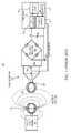
- FIG. 1is a figurative and schematic diagram illustrating a conventional Radio Frequency Identification (RFID) near-field communication system 100 with an active RFID reader 101 and a passive RFID tag 103 that responds to the active RFID reader 101 via backscattering, very much like a radar illuminating a target.
- the active RFID reader 101includes a magnetic loop antenna 105 which is placed in close proximity with a magnetic loop antenna 107 of the passive RFID tag 103 to establish a magnetic field 106 .
- the passive RFID tag 103further includes a shunt capacitance C TUNE , a switch SW, a full-wave rectifier 109 and a storage capacitor C S coupled to the magnetic loop antenna 107 , in which C S develops a supply voltage VS for providing power to an RFID tag integrated circuit (IC) 111 .
- the switch SWincludes a series resistance R SW (which may or may not be a separate physical resistor, but may instead represent the series resistance of the switch SW).
- the RFID tag IC 111is shown including a receive (RX) detector 113 , control logic 115 , transmit (TX) switch control 117 and memory 119 .
- the active RFID reader 101operates as an interrogator which develops the magnetic field 106 to provide power and which further modulates the magnetic field 106 to enable communication with tags that are within their range, such as the passive RFID tag 103 .
- the magnetic loop antenna 107develops inductive current which is converted to voltage across CS for providing power to the RF tag IC 111 .
- the active RFID reader 101further modulates the magnetic field 106 to send data, which is detected by the RX detector 113 .
- modulationmay be according to any suitable form, such as amplitude modulation (AM) (e.g., on-off key AM), frequency modulation (FM) or phase modulation (PM).
- AMamplitude modulation
- FMfrequency modulation
- PMphase modulation
- the control logic 115retrieves the data and may provide a response by controlling the switch SW via the TX switch control 117 .
- the active RFID reader 101broadcasts a steady radio frequency (RF) power level via the magnetic field 106 , and the passive RFID tag 103 modulates the impedance of its RF load attached to the magnetic loop antenna 107 by adjusting its reflectivity by controlling the switch SW coupled with other passive components, such as C TUNE .
- the active RFID reader 101then receives the data back from the passive RFID tag 103 as a variation in reflection of its transmitted power.
- RFradio frequency
- the passive RFID tag 103can only send data to the nearby interrogator/reader, e.g., the active RFID reader 101 , and the active RFID reader 101 sends data (by induced current) to the passive RFID tag 103 .
- the passive RFID tag 103sends data back to the active RFID reader 101 only while it broadcasts energy (e.g., while sending an un-modulated carrier signal via the magnetic field 106 ).
- the passive RFID tag 103does not store energy for later use, and it does not generate its own RF carrier.
- the magnetic loop antennas 105 and 107are typically rather large and are not commonly available for many types of devices, such as cellular phones or smart phones and the like.
- the active RFID reader 101for example, is typically a tablet or hand scanner or the like particularly configured for RFID tag communications.
- the conventional RFID tag communication systemssuch as the communication system 100 , have several disadvantages.
- the disadvantagesinclude, for example, the need to have a relatively-large antenna to obtain sufficient energy-harvesting efficiency for the low carrier frequency (long wavelength of over 22 meters) and the lack of available reader interfaces in common devices like mobile phones and portable computers and the like.
- the conventional RFID tag communication systemsoperate in lower frequency ranges, such as tens of MHz, and operate at relatively low data rates, such as less than 1 megabit per second (Mbps).
- standard microwave frequency communicationse.g., Wi-Fi, Bluetooth, etc.
- An autonomous battery-free microwave frequency communication deviceincludes a capacitance, at least one antenna, a microwave energy harvesting system, a microwave frequency transceiver, and a control system.
- the microwave energy harvesting systemis configured to harvest and store microwave energy received via the antenna onto the capacitance.
- the microwave frequency transceiveris empowered by energy stored on the capacitance, and is configured to autonomously generate a microwave frequency carrier and to autonomously transmit information using the microwave frequency carrier according to a predetermined communications protocol via the antenna.
- the control systemis empowered by energy stored on the capacitance, and is configured to provide information for transmission.
- a method of performing autonomous communications by a battery-free deviceincludes receiving microwave energy via at least one antenna, harvesting the received microwave energy and storing harvested energy on a storage capacitance, generating at least one data frame formatted according to a first communications protocol using energy stored on the storage capacitance, generating a microwave frequency carrier using energy stored on the storage capacitance, modulating the microwave frequency carrier with the data frame using energy stored on the storage capacitance to provide a modulated information, and transmitting the modulated information via the at least one antenna using energy stored on the storage capacitance.
- a wireless radio frequency tag deviceincludes a physical article configured for a predetermined purpose, and an autonomous battery-free microwave frequency communication device according to embodiments of the present invention and embedded on the physical article to enhance the predetermined purpose.
- the physical articlemay take on any of many different types of formats, such as wristbands, advertisement flyers, cards, etc.
- FIG. 1is a figurative and schematic diagram illustrating a conventional Radio Frequency Identification (RFID) near-field communication system with an active RFID reader and a passive RFID tag that responds to the active RFID reader using backscattering communications;
- RFIDRadio Frequency Identification
- FIG. 2is a block diagram of an autonomous battery-free microwave frequency RF tag according to one embodiment of the present invention
- FIG. 3is a block diagram of a communication system according to one embodiment of the present invention including the battery-free microwave frequency RF tag of FIG. 2 communicatively coupled with a battery powered device via bi-directional communication link;
- FIG. 4is a block diagram of a communication system according to one embodiment of the present invention including the battery-free microwave frequency RF tag of FIG. 2 communicatively coupled with the device of FIG. 3 via a bi-directional communication link, which further includes an energy transfer link for transfer of energy from the powered device to the battery free tag device;
- FIG. 5is a block diagram showing a wireless disposable wristband incorporating a battery-free microwave frequency RF tag (configured according to any of the embodiments of the tag described herein) which communicates with the device of FIG. 3 using microwave frequency communications according to one embodiment;
- FIG. 6is a block diagram shows a wireless advertisement or flyer (AD/FLYER) incorporating a battery-free microwave frequency RF tag (configured according to any of the embodiments of the tag described herein) which communicates with the device of FIG. 3 using microwave frequency communications according to one embodiment;
- AD/FLYERwireless advertisement or flyer
- FIG. 6shows a wireless advertisement or flyer (AD/FLYER) incorporating a battery-free microwave frequency RF tag (configured according to any of the embodiments of the tag described herein) which communicates with the device of FIG. 3 using microwave frequency communications according to one embodiment;
- FIG. 7is a block diagram shows a wireless credit, debit, and/or loyalty card incorporating a battery-free microwave frequency RF tag (configured according to any of the embodiments of the tag described herein) which communicates with the device of FIG. 3 using microwave frequency communications according to one embodiment;
- FIG. 8is a figurative diagram showing a portion or fragment of a basic protocol for charging a battery-free microwave frequency RF tag and an initial response sent by the tag for initialization of communications according to one embodiment
- FIG. 9is a figurative diagram showing a fragment of the 802.11 WLAN protocol, in which charging a battery-free microwave frequency RF tag is accomplished by beaconing according to one embodiment
- FIG. 10is a block diagram of an exemplary microwave energy harvesting and storage network implemented according to an embodiment of the present invention.
- FIGS. 11 and 12illustrate various conventional circuits which may be used to implement portions of the exemplary microwave energy harvesting and storage network of FIG. 10 ;
- FIG. 13is a schematic and block diagram of a microwave frequency radio transceiver which may be used to implement the microwave frequency transceiver of the tag of FIG. 2 .
- Various embodiments disclosed hereinincorporate a microwave frequency energy harvesting system coupled to one or more antenna(s) tuned to a range of frequencies and a microwave-frequency transceiver for communications in a network of two or more devices.
- Energy harvestingmay occur when the receiving antenna(s) on the battery-free device is (are) in the far field, the near field, or between the near and far fields of the transmitting antenna(s) in the device providing energy.
- the same or a different antenna or set of antennasis used for communications.
- a different set of antennasmay be used either to achieve additional gain from directive reception for energy harvesting while simultaneously allowing omni-directional transmission of data from the battery-free device to the device providing energy and possibly other devices or to enable different frequency bands to be used for powering the battery-free device and communicating with the battery-free device.
- the battery-free devicemay implement an IEEE (Institute of Electrical and Electronics Engineers) 802.11-compliant radio with an active power amplifier in the 2.4-2.5 GHz band and also implement an energy-harvesting system that draws power from the received 802.11 signal and is tuned to the 2.4-2.5 GHz band.
- the battery-free devicegenerates its own microwave frequency carrier signal using dedicated internal circuitry, such as phase-locked loops (PLLs), mixers, and reference frequency oscillators.
- PLLsphase-locked loops
- this devicemay use multiple antennas with directional reception to collect a larger amount of received power from the 802.11 transmissions, each directional antenna coupled to one or more energy-harvesting circuit(s).
- the battery-free devicemay implement a Bluetooth compliant or Wi-Fi compliant radio in the 2.4-2.5 GHz band (Wi-Fi or Bluetooth) or 4.9-6.0 GHz band (Wi-Fi) and may also implement one or more energy-harvesting circuits(s) tuned to one or more of the cellular telephony uplink transmission bands.
- Wi-Fiis a trademark of the Wi-Fi Alliance, which includes various wireless local area network (WLAN) protocols based on the IEEE 802.11 standard along with other wireless communication protocols as known to those of ordinary skill in the art.
- WLANwireless local area network
- Bluetoothis a wireless technology based on an industry group specification typically used for exchanging data over relatively short distances.
- the controller subsystemmay include finite-state machines, microcontrollers, microprocessors, bus interfaces, and/or peripheral circuitry.
- Memorymay include non-volatile and/or volatile memory and may be one-time and/or many-time programmable.
- Various embodiments disclosed hereinmay incorporate passive networks for boosting the voltage received from the antenna(s) in order to more effectively activate subsequent voltage rectifier circuits which may otherwise not be capable of capturing substantial power.
- Various embodiments disclosed hereinalso incorporate the microwave frequency battery-free device in a network involving a communication device that also provides energy to the battery-free device and a further communication link from the device providing energy to the battery-free device to a wireless access point or base station that provides a further connection to servers on an intranet or the larger Internet.
- An intranet in this descriptionmay be a corporate or hospital network hosted in a building or through distributed data centers or a network including Virtual Private Network (VPN) links. Examples are included showing usages of the autonomous battery-free microwave-frequency radio device in a network possibly including wireless access points or cellular base stations and servers in an intranet or the larger Internet.
- the server(s)receive(s) data from the phone or other device that connects to the battery-free device and provides it energy; these data may include processed information from the battery-free device.
- the server(s)may send responses to the processed information back to the phone or other device connected to the battery-free device.
- FIG. 2is a block diagram of an autonomous battery-free microwave frequency RF tag 200 according to one embodiment of the present invention.
- the tag 200includes a microwave frequency antenna 201 coupled to a microwave frequency transceiver 203 .
- the microwave frequency transceiver 203is further coupled via a host bus 205 to a controller 207 .
- the controllermay be configured in any suitable manner, such as a microprocessor or other type of processor, a programmable state machine or the like, a hard-coded state machine or the like, etc.
- the controller 207is coupled to a memory 209 .
- the microwave frequency transceiver 203is also shown coupled to an energy harvesting system 211 , which stores energy on at least one energy storage capacitor C 1 . Additional storage capacitors may be included.
- N storage capacitors C 1 -CNare shown coupled to the energy harvesting system 211 (in which N is any positive integer including zero).
- the energy harvesting system 211may include one or more separate energy harvesting circuits.
- the energy harvesting system 211develops a regulated supply voltage VDD, which is provided to other components in the tag 200 , such as the microwave frequency transceiver 203 , the controller 203 , and the memory 209 .
- the memory 209includes non-volatile memory 213 .
- the non-volatile memory 213is desired to preserve information when the tag 200 has exhausted its stored energy supply provided by charge on the one or more capacitors C 1 -CN.
- the memory 209may include volatile memory, such as random access memory (RAM) 215 or the like (shown in dashed lines). In certain configurations the RAM 215 may be omitted as consuming significant energy.
- RAMrandom access memory
- the tag 200is a single antenna system in which the microwave antenna 201 is used for both energy harvesting by the energy harvesting system 211 and communications by the microwave frequency transceiver 203 .
- one or more additional microwave antennassuch as shown at 204 , may be included and coupled to the microwave frequency transceiver 203 . In this case the multiple antennas are shared between the microwave frequency transceiver 203 and the energy harvesting system 211 .
- one or more additional microwave antennassuch as shown at 206 , may be included and coupled to the energy harvesting system 211 . In this case, the one or more antennas coupled to the microwave frequency transceiver 203 are used for data communications, and the one or more antennas coupled to the energy harvesting system 211 are used for energy harvesting and storage.
- the energy harvesting system 211is coupled either to the same antenna(s) used by the microwave frequency transceiver 203 or to separate antennas. Separate antennas may be preferable in the case that the tag 200 is configured to communicate with far-away devices that may be placed in arbitrary positions with respect to the tag 200 . In this case, the long-distance path may prefer the use of omni-directional antennas, while the energy harvesting system 211 prefers strongly directional antennas to pick up a maximum amount of power from a nearby transceiver that may be oriented in a particular manner.
- One or more antennasmay be used; more than one antenna may be used if “sectorized” transmission with high-gain antennas is desired to improve range while also enabling flexibility in the positioning of other devices that are providing energy and/or information.
- the tag 200is “battery-free” meaning that it does not receive power from any other source other than that which is stored on the capacitance of the energy storage capacitors C 1 -CN.
- the tag 200is “autonomous” meaning that it does not rely on energy being transmitted by an external device at the same time that that tag 200 transmits information.
- the microwave frequency transceiver 203 of the tag 200generates its own microwave frequency carrier and modulates the carrier for data transmission rather than relying on an un-modulated carrier provided by an external device.
- the microwave frequency transceiver 203can independently receive, demodulate and process information received via the one or more antennas.
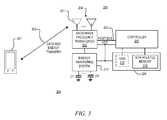
- FIG. 3is a block diagram of a communication system 300 according to one embodiment of the present invention including the battery-free microwave frequency RF tag 200 communicatively coupled with a battery powered device 301 via bi-directional communication link 303 .
- the tag 200includes at least one shared omni-directional antenna (e.g., 201 ) or multiple high-gain shared antennas 201 - 201 which is/are used to harvest energy and send/receive data.
- the battery powered device 301is a phone (cellular phone or smart phone or the like) or a tablet or similar type device which communicates according to at least one standard communication protocol, such as Wi-Fi or Bluetooth or the like.
- FIG. 4is a block diagram of a communication system 400 according to one embodiment of the present invention including the battery-free microwave frequency RF tag 200 communicatively coupled with the device 301 via a bi-directional communication link 403 , which further includes an energy transfer link 405 for transfer of energy from device 301 to tag 200 .
- the tag 200includes at least one shared omni-directional antenna (e.g., 201 ) or multiple high-gain shared antennas 201 - 201 which is/are used to send/receive data.
- the tag 200further includes one or more antennas 206 coupled to the energy harvesting system 211 for energy transfer via the energy transfer link 405 .
- the communication link 403is according Wi-Fi or Bluetooth or the like, in which separate antennas are used for the microwave frequency transceiver 203 and the energy harvesting system 211 .
- generally one (omni-directional) antennais used for the microwave frequency transceiver 203 and one or more antennas 206 are used for the energy harvesting system 211 .
- a separate energy harvesting circuit within the energy harvesting system 211is coupled to each antenna 206 .
- the energy transfer link 405is facilitated in any one or more of several different communication methods.
- the Wi-Fi or Bluetooth communications transmitted by the device 301are also used for the energy transfer link 405 to provide energy for charging the capacitor(s) C 1 -CN.
- the device 301provides energy via the energy transfer link 405 from cellular uplink transmissions. In this manner, separate frequency bands and protocols may be used for energy harvesting and data communications.
- the Wi-Fi or Bluetooth microwave frequency bandsare used for communication and a transceiver in one or more of the licensed cellular bands provides energy to be stored for data communication use.
- the communications via link 403may occur at the same or a different and even mutually-exclusive time from the energy transfer via link 405 . While different antennas may likely be used in different bands, it is possible for all bands to be tuned using an antenna and associated passive network that are resonant in multiple bands, although at a potential reduction in efficiency.
- FIG. 5is a block diagram showing a wireless disposable wristband 501 incorporating a battery-free microwave frequency RF tag 503 (configured according to any of the embodiments of the tag 200 described herein) which communicates with the device 301 using microwave frequency communications according to one embodiment.
- the device 301is a smart phone or the like running a software application, in which the phone may read from and, in various embodiments, write to the tag 503 incorporated on the wristband 501 .
- the tag 503contains sensors and/or stored information or the like, such as, for example, medical records, administered medications or procedures (like CT scans) that had been performed on a patient earlier during hospitalization.
- the wireless disposable wristband 501may also include sensors such as relative body temperature, pulse, or a pulse oximeter (SPO2) (not shown).
- the microwave frequenciesmay include the bands used for Bluetooth or Wi-Fi and/or one or more of the licensed cellular bands as previously described.
- the device 301may further communicate with additional devices, such as an access point that routes its data to and from a server or the like over either the Internet or a closed intranet or the like.
- additional devicessuch as an access point that routes its data to and from a server or the like over either the Internet or a closed intranet or the like.
- the serverincludes or is otherwise coupled to one or more storage devices.
- FIG. 6is a block diagram that shows a wireless advertisement or flyer (AD/FLYER) 601 incorporating a battery-free microwave frequency RF tag 603 (configured according to any of the embodiments of the tag 200 described herein) which communicates with the device 301 using microwave frequency communications according to one embodiment.
- the embodiment of FIG. 6is similar to that shown in FIG. 5 in which the wireless AD/FLYER 601 and tag 603 replaces the wireless disposable wristband 501 and RF tag 503 .
- the device 301is a smart phone or the like running a software application, in which the phone may read from and, in various embodiments, write to the tag 603 incorporated on the wristband 501 .
- the wireless AD/FLYER 601 with tag 603enables localized promotions to be deployed, for example, a coupon that enables an owner of the device 301 to receive a discount at a recently-opened nearby store in the same group or chain. It also allows localization of potential customers, as the tag 603 may communicate also with store infrastructure (e.g., a nearby Wi-Fi Access Point or AP).
- Microwave frequenciesmay include the bands used for Bluetooth or Wi-Fi and/or one or more of the licensed cellular bands.
- the device 301may further communicate with additional devices, such as an access point that routes its data to and from a server or the like over either the Internet or a closed intranet or the like.
- additional devicessuch as an access point that routes its data to and from a server or the like over either the Internet or a closed intranet or the like.
- the serverincludes or is otherwise coupled to one or more storage devices.
- FIG. 7is a block diagram that shows a wireless credit, debit, and/or loyalty card 701 incorporating a battery-free microwave frequency RF tag 703 (configured according to any of the embodiments of the tag 200 described herein) which communicates with the device 301 using microwave frequency communications according to one embodiment.
- the embodiment of FIG. 7is similar to that shown in FIG. 5 in which the card 701 and tag 703 replaces the wireless disposable wristband 501 and RF tag 503 .
- the device 301is a smart phone or the like running a software application, in which the phone may read from and, in various embodiments, write to the tag 703 incorporated on the card 701 .
- the card 701enables localized promotions to be deployed and offers the possibility of “one card in the wallet” for multiple purposes (identification (ID), payment, promotions).
- Microwave frequenciesmay include the bands used for Bluetooth or Wi-Fi and/or one or more of the licensed cellular bands.
- the device 301may further communicate with additional devices, such as an access point that routes its data to and from a server or the like over either the Internet or a closed intranet or the like.
- additional devicessuch as an access point that routes its data to and from a server or the like over either the Internet or a closed intranet or the like.
- the serverincludes or is otherwise coupled to one or more storage devices.
- a tagis a device or label or the like that has at least the property that it retains and makes available information about something to which it is associated (e.g., a price tag on merchandise, a hospital wristband, etc.). It may also update its own information about the thing to which it is associated.
- a physical articlesuch as a physical body or physical object or the like, has a physical form to achieve a particular or predetermined purpose or function, in which an autonomous battery-free microwave frequency RF tag (e.g., tag 503 , 603 , 703 according to the embodiment of tag 200 ) is embedded or provided on the physical article to enhance the targeted purpose or function.
- the wristband 501is physically configured to be held on a person's wrist, and the tag 503 stores or otherwise provides information associated with that person and/or a facility or event.
- the AD/FLYER 601is physically configured to capture the attention of an onlooker or passer-by, and the tag 603 is provided on the AD/FLYER 601 to convey information or otherwise to offer a benefit to that person for a commercial or business purpose or the like of at least one commercial entity (e.g., localized promotion(s), coupon(s), discount(s), local business advertisement, etc.).
- the card 701is physically configured in similar manner as a credit or debit card or the like to be carried by a person, and the tag 703 stores data and information to facilitate one or more commercial transactions (e.g., localized promotions, one card in the wallet, ID, payment, etc.).
- commercial transactionse.g., localized promotions, one card in the wallet, ID, payment, etc.
- FIG. 8is a figurative diagram showing a portion or fragment of a basic protocol for charging a battery-free microwave frequency RF tag 803 and an initial response sent by the tag 803 for initialization of communications according to one embodiment.
- the tag 803is configured according to any of the embodiments of the tag 200 described herein.
- a device 801which supplies energy to the tag 803 , sends a sequence of one or more charging packets 805 to the tag 803 .
- the charging packets 805may be formatted in a manner to avoid any interoperability issues with other devices using the same band, such as those using the same protocol.
- the charging packets 805may be beacons, which convey timing and network status information on a periodic basis, a form of Request, for example, a Request to Send (RTS) or data frame, or a form of Response, for example a Clear to Send (CTS) or data frame. Since there is no expectation of a response to a Beacon frame, a Beacon is a good choice for the charging packet 805 . A CTS sent to the sender's own device address also results in no expectation of a response. A RTS may be sent repeatedly.
- RTSRequest to Send
- CTSClear to Send
- the tag 803Once sufficiently charged, the tag 803 returns a response 807 back to the device 801 . In this manner, further two-way communication may occur. It is appreciated that once the tag 803 is sufficiently charged, the response 807 may be sent autonomously by the tag 803 , such that it may be performed at any time even when the device 801 (or any other device) is not transmitting information or otherwise generating microwave energy in the wireless medium. The energy stored by the tag 803 may further be used at a somewhat later time to communicate with a different device.
- FIG. 9is a figurative diagram showing a fragment of the 802.11 WLAN protocol, in which charging a battery-free microwave frequency RF tag 903 is accomplished by beaconing according to one embodiment.
- a device 901which supplies energy to the tag 903 , sends a sequence of one or more beacons 905 to the tag 903 .
- the device 901is configured as an access point (AP), a Personal Basic Service Set (PBSS) Central Point (PCP) device, a Wi-Fi Direct Group Owner, a member of a Wi-Fi Direct Group or an Independent Basic Server Set Station (IBSS STA) powered by a power supply or battery or the like.
- APaccess point
- PBSSPersonal Basic Service Set
- PCPCentral Point
- Wi-Fi Direct Group Ownera Wi-Fi Direct Group Owner
- IBSS STAIndependent Basic Server Set Station
- the tag 903responds with a probe request 907 and the two devices 901 and 903 become associated.
- 802.11 beaconstypically include both implicit (based on relative temp
- a variable number of beacons 905is transmitted by the device 901 to charge the tag 903 .
- the particular number of beacons 905is determined by a number of factors, such as the distance and/or orientation between the 901 and 903 . More time for charging (more beacons 905 ) may be needed for a larger distance between 901 and 903 , because less energy is harvested per packet due to loss in the wireless channel.
- the tag 903may send a probe request 907 to the device 901 in an autonomous manner as illustrated.
- the probe request 907is the first step in associating 901 and 903 in any band that allows active scanning by new devices for other devices.
- the device 901responds with a probe response 909 , and other frame exchanges could then occur to enable the tag 903 to send and receive larger amounts of data to/from the device 901 .
- FIG. 10is a block diagram of an exemplary microwave energy harvesting and storage network 1000 implemented according to an embodiment of the present invention which may be used to implement the energy harvesting system 211 including each of one or more energy harvesting circuits within the system 211 .
- a passive network 1003is coupled to an antenna 1001 for amplifying a received microwave signal in a particular band or band(s). The antenna 1001 and the passive network 1003 are collectively configured to generate the largest possible output voltage, shown as an AC voltage VRF.
- a rectifier & energy storage circuit 1005receives VRF and produces a DC voltage VDC which is stored by an energy-storage capacitance, such as the capacitor(s) C 1 -CN represented by a capacitor coupled between VDC and GND.
- a supply voltage generator circuit 1007receives VDC and produces the regulated voltage VDD which is sufficiently accurate as a source voltage for digital and analog/RF circuits.
- the antenna 1001represents any of the antennas 201 , 204 and/or 206 previously described.
- the passive network 1003 and the rectifier & energy storage circuit 1005collectively harvest and store energy received via one or more antennas.
- harvestand its various forms as used herein means the conversion of received microwave energy into energy (e.g., voltage) for storage on the storage capacitance, which is used to develop the supply voltage VDD for remaining circuitry in the tag device.
- the passive network 1003 , the rectifier & energy storage circuit 1005 , and the supply voltage generator circuit 1007may each be implemented according to well-known or otherwise available configurations.
- FIG. 11shows several conventional configurations for implementing the passive network 1003 , including a wideband step-up transformer 1101 , an LC resonant structure 1103 , and a resonant pi-network 1105 .
- the wideband step-up transformer 1101boosts a voltage of the antenna (shown as ANT) by a factor 1:N using magnetically-coupled coils to produce the output VRF.
- the voltage of VRFis thus N times larger than the antenna voltage ANT, and AC voltages within a large range of frequencies are boosted.
- the LC resonant structure 1103includes an inductor L and capacitors CA and CB which are configured as illustrated to provide narrowband voltage gain from ANT to VRF.
- the resonant pi-network 1105includes an inductor L and capacitors CA and CB which are configured as illustrated to implement a low-pass filter with cut-off frequency with adjustable in-band gain. Many other similar types circuits may be employed for implementing the passive network 1003 .
- FIG. 12shows several conventional configurations for implementing the rectifier & energy storage circuit 1005 , each configured with a combination of one or more diodes and one or more capacitors, including a half-wave rectifier 1201 , a full-wave rectifier 1203 , a voltage doubling rectifier 1205 for producing higher DC output voltage, and a two series-stacked voltage doubling rectifier circuit 1207 for further increasing DC output voltage beyond that produced by 1205 .
- Many other similar types circuitsmay be employed for implementing the rectifier & energy storage circuit 1005 .
- Each of the diodesmay be configured in any suitable manner as known by those of ordinary skill in the art, such as a simple PN junction diode, a diode-connected metal-oxide semiconductor, field-effect transistor (MOSFET), a Schottky diode, a diode-connected bipolar junction transistor (BJT), etc.
- a simple PN junction diodea diode-connected metal-oxide semiconductor, field-effect transistor (MOSFET), a Schottky diode, a diode-connected bipolar junction transistor (BJT), etc.
- MOSFETfield-effect transistor
- BJTbipolar junction transistor
- the supply voltage generator 1007may be configured using many types of voltage converters or regulators or the like as known by those of ordinary skill in the art, such as, for example, a switching DC-DC converter (buck, boost, buck-boost, etc.) or a low dropout (LDO) regulator or the like.
- a switching DC-DC converterbuck, boost, buck-boost, etc.
- LDOlow dropout
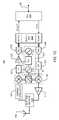
- FIG. 13is a schematic and block diagram of a microwave frequency radio transceiver 1300 which may be used to implement the microwave frequency transceiver 203 of the tag 200 .
- a media access control (MAC) device 1301interfaces the controller 207 via the host bus 205 and is further coupled to a digital physical layer (PHY) device 1303 .
- the MAC 1301 and the TX PHY portion of the PHY device 1303controls the radio and turns bits from the controller 207 into modulated symbols (e.g. BPSK or QPSK constellation points or an OFDM multiplex with some sub-carrier constellations), in which the modulated symbols are interpolated and pulse-shaped and then provided to the input of a digital to analog converter (DAC) 1305 .
- modulated symbolse.g. BPSK or QPSK constellation points or an OFDM multiplex with some sub-carrier constellations
- the MAC 1301 and/or the digital PHY 1303 and/or the DAC 1305individually or collectively form a frame generation circuit.
- the analog output of the DAC 1305is provided to the input of a low-pass filter (LPF) 1307 for removing aliases from the DAC 1305 .
- the LPF 1307may provide gain or attenuation.
- the filtered output of the LPF 1307is provided to an input of an in-phase quadrature-phase (90-degree) mixer 1309 , which translates the filtered signal from baseband (centered at DC) to some relatively-higher carrier frequency, e.g., 2.4-2.5 GHz.
- the mixer 1309may be referred to as a modulator circuit for information to be transmitted, and further as a demodulator circuit for received information.
- the transceiver 1300includes a carrier frequency generator 1311 , which includes an oscillator 1313 generating a frequency reference signal F REF .
- the oscillator 1313may be implemented by a crystal oscillator or the like and may be simply pass through an externally-generated F REF reference frequency signal.
- the F REF signalprovides the input to a Phase-Locked Loop (PLL) 1315 and a voltage controlled oscillator (VCO) 1317 for generating the microwave carrier frequency signal MC.
- PLLPhase-Locked Loop
- VCOvoltage controlled oscillator
- the MC signalis provided to an input of the mixer 1309 .
- a TX output of the mixer 1309is provided to the input of a power amplifier (PA) 1319 to amplify the signal for transmission at a greater distance in the wireless channel.
- PApower amplifier
- the PA 1319is provide to an input of a matching network 1321 , which provides additional passive gain in the receiver path.
- the matching network 1321is coupled to an antenna 1001 for transmitting a data packet in the wireless channel.
- the antenna 1001represents any of the antennas 201 , 204 and/or 206 previously described.
- the matching network 1321is not provided and the output of the PA 1319 drives the antenna 1001 .
- the DAC 1305 and the LPF 1307 and/or the mixer 1309 and/or the PA 1319 and/or the matching network 1321may be individually or collectively referred to as a transmitter circuit.
- signals received via the antenna 1001are provided through a receiving circuit including the matching network 1321 (if provided), which in one embodiment is a high-gain passive matching network in the receive path.
- the received signalis shown provided to a variable attenuator 1323 (also part of the receiver circuit) which feeds an RX input of the mixer 1309 .
- the mixer 1309reduces the frequency of the received signal from a relatively-higher frequency to some relatively lower frequency, e.g., baseband (DC) or a low intermediate frequency (IF) such as 1 MHz.
- the baseband signal output from the mixer 1309is provided to an LPF 1325 which blocks out-of-channel and out-of-band interference and which may provide additional gain or attenuation.
- the output of the LPF 1325is operably coupled to a variable gain amplifier (VGA) 1327 , which may provide larger values of gain after removing adjacent-channel interference.
- VGA 1327is coupled to an analog to digital converter (ADC) 1329 , which provides a sampled, quantized representation of the input signal to the RX PHY portion of the digital PHY 1303 .
- ADCanalog to digital converter
- the output of the RX PHYis provide to the MAC 1301 .
- the RX PHY and the MAC 1301control the radio and demodulates the output samples of the ADC 1329 and then decodes the bits intended for the tag device.
- the bitsare provided to the controller 207 via the host bus 205 .
- the MAC 1301 and/or the digital PHY 1303 and/or the ADC 1329individually or collectively form a frame processing circuit.
- microwave frequency transceiver 203may be implemented according to many alternative configurations.
- the microwave frequency transceiver 1300enables any of the tags described herein to be autonomous since it generates its own microwave frequency carrier (e.g., MC) which is used for communications including transmitting data to external devices. Data communications and energy harvesting may each occur on any one or more of multiple microwave frequency bands.
- the microwave frequency communicationsmay be implemented according to any one or more of the standard communication protocols, such as Wi-Fi or Bluetooth or the like, for enabling communication with common devices, such as smart phones or the like.
- circuits described hereinmay be implemented in any suitable manner including logic devices or circuitry or the like.
- the circuits described hereinmay include inverting devices implementing positive or negative logic or the like in which any signal may be inverted.
- the present inventionis described using circuits operating with digital or binary bytes and words where it is understood that the circuitry applies to digital or binary values comprising any number of bits.
Landscapes
- Engineering & Computer Science (AREA)
- Physics & Mathematics (AREA)
- Computer Hardware Design (AREA)
- Microelectronics & Electronic Packaging (AREA)
- Electromagnetism (AREA)
- General Physics & Mathematics (AREA)
- Theoretical Computer Science (AREA)
- Near-Field Transmission Systems (AREA)
Abstract
Description
Claims (21)
Priority Applications (1)
| Application Number | Priority Date | Filing Date | Title |
|---|---|---|---|
| US13/092,586US8797146B2 (en) | 2010-04-27 | 2011-04-22 | Autonomous battery-free microwave frequency communication system |
Applications Claiming Priority (2)
| Application Number | Priority Date | Filing Date | Title |
|---|---|---|---|
| US32829110P | 2010-04-27 | 2010-04-27 | |
| US13/092,586US8797146B2 (en) | 2010-04-27 | 2011-04-22 | Autonomous battery-free microwave frequency communication system |
Publications (2)
| Publication Number | Publication Date |
|---|---|
| US20110260839A1 US20110260839A1 (en) | 2011-10-27 |
| US8797146B2true US8797146B2 (en) | 2014-08-05 |
Family
ID=44815317
Family Applications (1)
| Application Number | Title | Priority Date | Filing Date |
|---|---|---|---|
| US13/092,586Active2032-06-09US8797146B2 (en) | 2010-04-27 | 2011-04-22 | Autonomous battery-free microwave frequency communication system |
Country Status (1)
| Country | Link |
|---|---|
| US (1) | US8797146B2 (en) |
Cited By (27)
| Publication number | Priority date | Publication date | Assignee | Title |
|---|---|---|---|---|
| US20130135084A1 (en)* | 2011-11-28 | 2013-05-30 | Tata Consultancy Services Limited | System and Method for Simultaneous Wireless Charging, Tracking And Monitoring Of Equipments |
| US20130249301A1 (en)* | 2012-03-21 | 2013-09-26 | Disney Enterprises, Inc., A Delaware Corporation | System And Method For Powering An RFID Module Using An Energy Harvesting Element |
| US20150356335A1 (en)* | 2013-01-16 | 2015-12-10 | A-Key S.R.L. | A control system for detecting the presence of equipment devices |
| US9533230B2 (en) | 2011-05-16 | 2017-01-03 | Disney Enterprises, Inc. | Ghost expressions based on ghost data augmented by user-provided information |
| US20170180075A1 (en) | 2014-02-11 | 2017-06-22 | University Of Washington | Wireless networking communication methods, systems, and devices operable using harvested power |
| WO2017132400A1 (en)* | 2016-01-26 | 2017-08-03 | University Of Washington | Backscatter devices including examples of single sideband operation |
| US9973367B2 (en) | 2014-02-11 | 2018-05-15 | University Of Washington | Apparatuses, systems, and methods for communicating using MIMO and spread spectrum coding in backscatter of ambient signals |
| US10033424B2 (en) | 2013-03-22 | 2018-07-24 | University Of Washington | Ambient backscatter transceivers, apparatuses, systems, and methods for communicating using backscatter of ambient RF signals |
| US10079616B2 (en) | 2014-12-19 | 2018-09-18 | University Of Washington | Devices and methods for backscatter communication using one or more wireless communication protocols including bluetooth low energy examples |
| US10360419B1 (en) | 2018-01-15 | 2019-07-23 | Universal City Studios Llc | Interactive systems and methods with tracking devices |
| US10461783B2 (en) | 2017-03-16 | 2019-10-29 | University Of Washington | Radio frequency communication devices having backscatter and non-backscatter communication modes and hardware re-use |
| US10537803B2 (en) | 2018-01-18 | 2020-01-21 | Universal City Studios Llc | Interactive gaming system |
| US10603564B2 (en) | 2018-01-03 | 2020-03-31 | Universal City Studios Llc | Interactive component for an amusement park |
| US10614271B2 (en) | 2018-01-15 | 2020-04-07 | Universal City Studios Llc | Interactive systems and methods |
| US10652073B2 (en) | 2016-04-04 | 2020-05-12 | University Of Washington | Backscatter devices and systems providing backscattered signals including OFDM packets |
| US10653957B2 (en) | 2017-12-06 | 2020-05-19 | Universal City Studios Llc | Interactive video game system |
| US10699084B2 (en) | 2018-01-15 | 2020-06-30 | Universal City Studios Llc | Local interaction systems and methods |
| US10790703B2 (en)* | 2016-12-19 | 2020-09-29 | Koji Yoden | Smart wireless power transfer between devices |
| US10812130B2 (en) | 2016-10-18 | 2020-10-20 | University Of Washington | Backscatter systems, devices, and techniques utilizing CSS modulation and/or higher order harmonic cancellation |
| US10818152B2 (en) | 2018-01-15 | 2020-10-27 | Universal City Studios Llc | Interactive systems and methods with feedback devices |
| US10846967B2 (en) | 2017-12-13 | 2020-11-24 | Universal City Studio LLC | Systems and methods for threshold detection of a wireless device |
| US10845975B2 (en) | 2018-03-29 | 2020-11-24 | Universal City Studios Llc | Interactive animated character head systems and methods |
| US10873363B2 (en) | 2015-08-12 | 2020-12-22 | University Of Washington | Backscatter devices and network systems incorporating backscatter devices |
| US10916059B2 (en) | 2017-12-06 | 2021-02-09 | Universal City Studios Llc | Interactive video game system having an augmented virtual representation |
| US10970725B2 (en) | 2017-11-29 | 2021-04-06 | Universal Studios LLC | System and method for crowd management and maintenance operations |
| US11212479B2 (en) | 2017-04-06 | 2021-12-28 | University Of Washington | Image and/or video transmission using backscatter devices |
| US20220082610A1 (en)* | 2020-09-17 | 2022-03-17 | Wiliot, LTD. | System and method for testing iot tags |
Families Citing this family (48)
| Publication number | Priority date | Publication date | Assignee | Title |
|---|---|---|---|---|
| US8817850B2 (en)* | 2011-04-08 | 2014-08-26 | Aviat U.S., Inc. | Systems and methods for transceiver communication |
| US20120329388A1 (en)* | 2011-06-27 | 2012-12-27 | Broadcom Corporation | NFC-Enabled Devices to Store and Retrieve Portable Application-Specific Personal Information for Use with Computational Platforms |
| JP5704016B2 (en)* | 2011-08-04 | 2015-04-22 | ソニー株式会社 | Wireless communication apparatus and electronic device |
| TWI442664B (en)* | 2011-08-19 | 2014-06-21 | Primax Electronics Ltd | Method for wireless charging of wireless peripheral device |
| US9123393B2 (en)* | 2011-09-01 | 2015-09-01 | HangZhou KiCun nformation Technology Co. Ltd. | Discrete three-dimensional vertical memory |
| MX2014003647A (en)* | 2011-09-27 | 2014-09-22 | Skyriver Communications Inc | Point-to-multipoint microwave communication. |
| WO2013089195A1 (en)* | 2011-12-14 | 2013-06-20 | Necカシオモバイルコミュニケーションズ株式会社 | Mobile terminal apparatus and method for adjusting rfid antenna resonance frequency thereof |
| EP2642423B1 (en)* | 2012-03-22 | 2015-06-10 | Nxp B.V. | Combined multifunctional RFID communication device |
| US20130260689A1 (en)* | 2012-03-30 | 2013-10-03 | Qualcomm Incorporated | Wirelessly Powered Input Device |
| US9245158B2 (en)* | 2012-04-05 | 2016-01-26 | Ricoh Co., Ltd. | Low power radio frequency communication |
| US9185646B2 (en)* | 2012-07-03 | 2015-11-10 | Samsung Electronics Co., Ltd. | Apparatus and method for wireless communication networks with energy harvesting |
| EP2685220A3 (en)* | 2012-07-10 | 2017-08-02 | Stichting IMEC Nederland | Self-powered sensor system |
| CH706836B1 (en)* | 2012-08-28 | 2014-10-31 | Yves Swiss Ag | Artificial nail with an embedded transponder and access to a software application, to be placed on a finger or toe nail. |
| US9465392B2 (en)* | 2012-11-14 | 2016-10-11 | International Business Machines Corporation | Dynamic temperature control for a room containing a group of people |
| US9696802B2 (en) | 2013-03-20 | 2017-07-04 | Microsoft Technology Licensing, Llc | Short range wireless powered ring for user interaction and sensing |
| EP2804153B1 (en)* | 2013-05-15 | 2018-11-21 | Nxp B.V. | Electronic lock, locking system and method of operating an electronic lock |
| US9705183B2 (en)* | 2013-06-19 | 2017-07-11 | Intermec Ip Corp. | Wirelessly reconfigurable antenna |
| US9864882B1 (en)* | 2013-07-19 | 2018-01-09 | Geotoll, Inc. | Energy harvesting for battery-less RFID tag devices with internal transmitters |
| TWI494862B (en)* | 2013-08-30 | 2015-08-01 | Univ Nat Cheng Kung | Harmonic radar radio frequency tag and system |
| EP3042522A4 (en)* | 2013-09-05 | 2017-04-12 | Intel Corporation | Techniques for wireless communication between a terminal computing device and a wearable computing device |
| US9473875B2 (en)* | 2014-03-06 | 2016-10-18 | Ricoh Co., Ltd. | Asymmetric wireless system |
| US9594427B2 (en) | 2014-05-23 | 2017-03-14 | Microsoft Technology Licensing, Llc | Finger tracking |
| US9582076B2 (en) | 2014-09-17 | 2017-02-28 | Microsoft Technology Licensing, Llc | Smart ring |
| GB201419668D0 (en)* | 2014-11-04 | 2014-12-17 | Univ Surrey | Energy harvesting in a wireless communication network |
| EP2950240A1 (en)* | 2014-11-04 | 2015-12-02 | idp invent ag | Transponder tag that is operable by a mobile telephone, portable object, mobile telephone, and corresponding methods |
| US10503939B2 (en)* | 2014-12-24 | 2019-12-10 | Intel Corporation | Method and apparatus for energy harvest from a proximity coupling device |
| US10355730B1 (en)* | 2015-07-25 | 2019-07-16 | Gary M. Zalewski | Wireless coded communication (WCC) devices with power harvesting power sources for processing internet purchase transactions |
| US9882282B2 (en)* | 2015-10-23 | 2018-01-30 | Apple Inc. | Wireless charging and communications systems with dual-frequency patch antennas |
| US12149651B2 (en) | 2015-11-03 | 2024-11-19 | Matthias Schütz | Transponder tag that is operable by a mobile telephone, portable object, mobile telephone, and corresponding methods |
| CN108370501B (en)* | 2015-12-15 | 2021-06-04 | 索尼公司 | Method, device and system for searching RFID (radio frequency identification) tag |
| US10346655B2 (en)* | 2016-12-07 | 2019-07-09 | Nec Corporation | Battery-free touch-aware user input using RFID tags |
| CN107566010B (en)* | 2017-09-28 | 2023-12-12 | 湖南伟民电子科技有限公司 | Microwave radio frequency communication device |
| US10747303B2 (en)* | 2017-10-13 | 2020-08-18 | Tactual Labs Co. | Backscatter hover detection |
| US20190181685A1 (en)* | 2017-12-08 | 2019-06-13 | Atmosic Technologies Inc. | Method and apparatus for wireless transmission and reception of power |
| EP3814979B1 (en)* | 2018-06-27 | 2024-02-28 | Telefonaktiebolaget Lm Ericsson (Publ) | A network control entity, an access point and methods therein for enabling access to wireless tags in a wireless communications network |
| US11178616B2 (en) | 2018-09-04 | 2021-11-16 | Atmosic Technologies Inc. | Staged wireless device wake-up |
| CA3117204A1 (en)* | 2018-10-31 | 2020-05-07 | Cornell University | System and method for ultra-high-resolution ranging using rfid |
| CN109728833B (en)* | 2019-02-11 | 2021-04-27 | 深圳市普威技术有限公司 | WiFi device |
| US11146104B2 (en) | 2019-05-03 | 2021-10-12 | Stmicroelectronics S.R.L. | Radiofrequency-powered device, corresponding system and method |
| GB2585352A (en)* | 2019-05-08 | 2021-01-13 | Saralon Gmbh | Wireless communication via modulated magnetic field reception |
| CN114207312B (en)* | 2019-07-15 | 2023-10-31 | 火石工业产品有限责任公司 | Gas spring components, suspension systems, and displacement and velocity sensors |
| CN115315706A (en)* | 2020-04-09 | 2022-11-08 | Oppo广东移动通信有限公司 | Electronic tags and data reading equipment |
| US11722347B2 (en) | 2021-01-14 | 2023-08-08 | University Of Washington | Backscatter devices and systems having digital architectures for OFDM backscatter |
| CN114091640B (en)* | 2021-11-09 | 2024-02-09 | 上海坤锐电子科技有限公司 | Electronic tag and electronic tag system |
| CN116233898A (en)* | 2021-12-06 | 2023-06-06 | 中兴通讯股份有限公司 | Data transmission method and device, storage medium and electronic equipment based on microwave equipment |
| FR3141304B1 (en)* | 2022-10-21 | 2025-02-07 | St Microelectronics Sa | METHOD FOR CONTACTLESS COMMUNICATION BETWEEN AN OBJECT AND A READER USING ACTIVE CHARGE MODULATION |
| CN116032328B (en)* | 2022-12-19 | 2024-06-18 | 陕西亿星远能科技有限公司 | Battery-less wireless communication system and method |
| CN117896204B (en)* | 2024-03-14 | 2024-05-28 | 季华实验室 | Microwave power supply communication method, device, electronic device and storage medium based on CAN |
Citations (12)
| Publication number | Priority date | Publication date | Assignee | Title |
|---|---|---|---|---|
| US20030104848A1 (en)* | 2001-11-30 | 2003-06-05 | Raj Brideglall | RFID device, system and method of operation including a hybrid backscatter-based RFID tag protocol compatible with RFID, bluetooth and/or IEEE 802.11x infrastructure |
| US20050186994A1 (en)* | 2000-09-27 | 2005-08-25 | Science Applications International Corporation | Method and system for energy reclamation and reuse |
| US20060180647A1 (en)* | 2005-02-11 | 2006-08-17 | Hansen Scott R | RFID applications |
| US20070008121A1 (en)* | 2005-06-09 | 2007-01-11 | Hart Matt E | RFID disablement detection of tampering |
| US20070109121A1 (en)* | 2005-08-04 | 2007-05-17 | Cohen Marc H | Harvesting ambient radio frequency electromagnetic energy for powering wireless electronic devices, sensors and sensor networks and applications thereof |
| US20070173214A1 (en)* | 2006-01-05 | 2007-07-26 | University Of Pittsburgh-Of The Commonwealth System Of Higher Education | Wireless autonomous device system |
| US20070281657A1 (en)* | 2005-01-20 | 2007-12-06 | Brommer Karl D | Microradio Design, Manufacturing Method and Applications for the use of Microradios |
| US20090284245A1 (en)* | 2008-05-13 | 2009-11-19 | Qualcomm Incorporated | Wireless power transfer for appliances and equipments |
| US20090318779A1 (en)* | 2006-05-24 | 2009-12-24 | Bao Tran | Mesh network stroke monitoring appliance |
| US20120007441A1 (en)* | 2007-06-01 | 2012-01-12 | Michael Sasha John | Wireless Power Harvesting and Transmission with Heterogeneous Signals. |
| US20120299706A1 (en)* | 2010-02-01 | 2012-11-29 | Georgia Tech Research Corporation | Multi-antenna signaling scheme for low-powered or passive radio communications |
| US8621245B2 (en)* | 2005-06-08 | 2013-12-31 | Powercast Corporation | Powering devices using RF energy harvesting |
- 2011
- 2011-04-22USUS13/092,586patent/US8797146B2/enactiveActive
Patent Citations (13)
| Publication number | Priority date | Publication date | Assignee | Title |
|---|---|---|---|---|
| US20050186994A1 (en)* | 2000-09-27 | 2005-08-25 | Science Applications International Corporation | Method and system for energy reclamation and reuse |
| US20030104848A1 (en)* | 2001-11-30 | 2003-06-05 | Raj Brideglall | RFID device, system and method of operation including a hybrid backscatter-based RFID tag protocol compatible with RFID, bluetooth and/or IEEE 802.11x infrastructure |
| US20070281657A1 (en)* | 2005-01-20 | 2007-12-06 | Brommer Karl D | Microradio Design, Manufacturing Method and Applications for the use of Microradios |
| US20060180647A1 (en)* | 2005-02-11 | 2006-08-17 | Hansen Scott R | RFID applications |
| US8621245B2 (en)* | 2005-06-08 | 2013-12-31 | Powercast Corporation | Powering devices using RF energy harvesting |
| US20070008121A1 (en)* | 2005-06-09 | 2007-01-11 | Hart Matt E | RFID disablement detection of tampering |
| US7400253B2 (en)* | 2005-08-04 | 2008-07-15 | Mhcmos, Llc | Harvesting ambient radio frequency electromagnetic energy for powering wireless electronic devices, sensors and sensor networks and applications thereof |
| US20070109121A1 (en)* | 2005-08-04 | 2007-05-17 | Cohen Marc H | Harvesting ambient radio frequency electromagnetic energy for powering wireless electronic devices, sensors and sensor networks and applications thereof |
| US20070173214A1 (en)* | 2006-01-05 | 2007-07-26 | University Of Pittsburgh-Of The Commonwealth System Of Higher Education | Wireless autonomous device system |
| US20090318779A1 (en)* | 2006-05-24 | 2009-12-24 | Bao Tran | Mesh network stroke monitoring appliance |
| US20120007441A1 (en)* | 2007-06-01 | 2012-01-12 | Michael Sasha John | Wireless Power Harvesting and Transmission with Heterogeneous Signals. |
| US20090284245A1 (en)* | 2008-05-13 | 2009-11-19 | Qualcomm Incorporated | Wireless power transfer for appliances and equipments |
| US20120299706A1 (en)* | 2010-02-01 | 2012-11-29 | Georgia Tech Research Corporation | Multi-antenna signaling scheme for low-powered or passive radio communications |
Non-Patent Citations (2)
| Title |
|---|
| Gast, Matthew S., "802.11 Wireless Networks: The Definitive Guide", 2002, O'Reilly, Sebanstopol, CA, 1st Edition, ISBN:0596001835, pp. 109-110.* |
| Miller, Brent; "Bluetooth Revealed"; published by Prentiss Hall PTR, Upper Saddle River, NY 07458; Copyright 2001; ISBN 0-13-090294-2; pp. 48-51.* |
Cited By (47)
| Publication number | Priority date | Publication date | Assignee | Title |
|---|---|---|---|---|
| US9533230B2 (en) | 2011-05-16 | 2017-01-03 | Disney Enterprises, Inc. | Ghost expressions based on ghost data augmented by user-provided information |
| US9178569B2 (en)* | 2011-11-28 | 2015-11-03 | Tata Consultancy Services Limited | System and method for simultaneous wireless charging, tracking and monitoring of equipments |
| US20130135084A1 (en)* | 2011-11-28 | 2013-05-30 | Tata Consultancy Services Limited | System and Method for Simultaneous Wireless Charging, Tracking And Monitoring Of Equipments |
| US20130249301A1 (en)* | 2012-03-21 | 2013-09-26 | Disney Enterprises, Inc., A Delaware Corporation | System And Method For Powering An RFID Module Using An Energy Harvesting Element |
| US20150356335A1 (en)* | 2013-01-16 | 2015-12-10 | A-Key S.R.L. | A control system for detecting the presence of equipment devices |
| US10033424B2 (en) | 2013-03-22 | 2018-07-24 | University Of Washington | Ambient backscatter transceivers, apparatuses, systems, and methods for communicating using backscatter of ambient RF signals |
| US10447331B2 (en) | 2013-03-22 | 2019-10-15 | University Of Washington | Ambient backscatter transceivers, apparatuses, systems, and methods for communicating using backscatter of ambient RF signals |
| US20170180075A1 (en) | 2014-02-11 | 2017-06-22 | University Of Washington | Wireless networking communication methods, systems, and devices operable using harvested power |
| US10382161B2 (en) | 2014-02-11 | 2019-08-13 | University Of Washington | Wireless networking communication methods, systems, and devices operable using harvested power |
| US9973367B2 (en) | 2014-02-11 | 2018-05-15 | University Of Washington | Apparatuses, systems, and methods for communicating using MIMO and spread spectrum coding in backscatter of ambient signals |
| US20180241604A1 (en) | 2014-02-11 | 2018-08-23 | University Of Washington | Apparatuses, systems, and methods for communicating using mimo and spread spectrum coding in backscatter of ambient signals |
| US10587445B2 (en) | 2014-02-11 | 2020-03-10 | University Of Washington | Apparatuses, systems, and methods for communicating using MIMO and spread spectrum coding in backscatter of ambient signals |
| US10270639B2 (en) | 2014-02-11 | 2019-04-23 | University Of Washington | Apparatuses, systems, and methods for communicating using MIMO and spread spectrum coding in backscatter of ambient signals |
| US10693521B2 (en) | 2014-12-19 | 2020-06-23 | University Of Washington | Devices and methods for backscatter communication using one or more wireless communication protocols including Bluetooth low energy examples |
| US10079616B2 (en) | 2014-12-19 | 2018-09-18 | University Of Washington | Devices and methods for backscatter communication using one or more wireless communication protocols including bluetooth low energy examples |
| US11411597B2 (en) | 2014-12-19 | 2022-08-09 | University Of Washington | Devices and methods for backscatter communication using one or more wireless communication protocols including Bluetooth low energy examples |
| US10873363B2 (en) | 2015-08-12 | 2020-12-22 | University Of Washington | Backscatter devices and network systems incorporating backscatter devices |
| WO2017132400A1 (en)* | 2016-01-26 | 2017-08-03 | University Of Washington | Backscatter devices including examples of single sideband operation |
| US10951446B2 (en) | 2016-01-26 | 2021-03-16 | University Of Washington | Backscatter devices including examples of single sideband operation |
| US10652073B2 (en) | 2016-04-04 | 2020-05-12 | University Of Washington | Backscatter devices and systems providing backscattered signals including OFDM packets |
| US10812130B2 (en) | 2016-10-18 | 2020-10-20 | University Of Washington | Backscatter systems, devices, and techniques utilizing CSS modulation and/or higher order harmonic cancellation |
| US10790703B2 (en)* | 2016-12-19 | 2020-09-29 | Koji Yoden | Smart wireless power transfer between devices |
| US10461783B2 (en) | 2017-03-16 | 2019-10-29 | University Of Washington | Radio frequency communication devices having backscatter and non-backscatter communication modes and hardware re-use |
| US11212479B2 (en) | 2017-04-06 | 2021-12-28 | University Of Washington | Image and/or video transmission using backscatter devices |
| US10970725B2 (en) | 2017-11-29 | 2021-04-06 | Universal Studios LLC | System and method for crowd management and maintenance operations |
| US12086819B2 (en) | 2017-11-29 | 2024-09-10 | Universal City Studios Llc | System and method for crowd management and maintenance operations |
| US11694217B2 (en) | 2017-11-29 | 2023-07-04 | Universal City Studios Llc | System and method for crowd management and maintenance operations |
| US11682172B2 (en) | 2017-12-06 | 2023-06-20 | Universal City Studios Llc | Interactive video game system having an augmented virtual representation |
| US10916059B2 (en) | 2017-12-06 | 2021-02-09 | Universal City Studios Llc | Interactive video game system having an augmented virtual representation |
| US10653957B2 (en) | 2017-12-06 | 2020-05-19 | Universal City Studios Llc | Interactive video game system |
| US11400371B2 (en) | 2017-12-06 | 2022-08-02 | Universal City Studios Llc | Interactive video game system |
| US10846967B2 (en) | 2017-12-13 | 2020-11-24 | Universal City Studio LLC | Systems and methods for threshold detection of a wireless device |
| US11130038B2 (en) | 2018-01-03 | 2021-09-28 | Universal City Studios Llc | Interactive component for an amusement park |
| US10603564B2 (en) | 2018-01-03 | 2020-03-31 | Universal City Studios Llc | Interactive component for an amusement park |
| US10614271B2 (en) | 2018-01-15 | 2020-04-07 | Universal City Studios Llc | Interactive systems and methods |
| US10360419B1 (en) | 2018-01-15 | 2019-07-23 | Universal City Studios Llc | Interactive systems and methods with tracking devices |
| US11379679B2 (en) | 2018-01-15 | 2022-07-05 | Universal City Studios Llc | Interactive systems and methods with tracking devices |
| US11379678B2 (en) | 2018-01-15 | 2022-07-05 | Universal City Studios Llc | Local interaction systems and methods |
| US10699084B2 (en) | 2018-01-15 | 2020-06-30 | Universal City Studios Llc | Local interaction systems and methods |
| US10839178B2 (en) | 2018-01-15 | 2020-11-17 | Universal City Studios Llc | Interactive systems and methods with tracking devices |
| US11983596B2 (en) | 2018-01-15 | 2024-05-14 | Universal City Studios Llc | Interactive systems and methods with tracking devices |
| US10818152B2 (en) | 2018-01-15 | 2020-10-27 | Universal City Studios Llc | Interactive systems and methods with feedback devices |
| US12190194B2 (en) | 2018-01-15 | 2025-01-07 | Universal City Studios, LLC | Local interaction systems and methods |
| US10537803B2 (en) | 2018-01-18 | 2020-01-21 | Universal City Studios Llc | Interactive gaming system |
| US10845975B2 (en) | 2018-03-29 | 2020-11-24 | Universal City Studios Llc | Interactive animated character head systems and methods |
| US20220082610A1 (en)* | 2020-09-17 | 2022-03-17 | Wiliot, LTD. | System and method for testing iot tags |
| US12352805B2 (en)* | 2020-09-17 | 2025-07-08 | Wiliot, LTD. | System and method for testing IoT tags |
Also Published As
| Publication number | Publication date |
|---|---|
| US20110260839A1 (en) | 2011-10-27 |
Similar Documents
| Publication | Publication Date | Title |
|---|---|---|
| US8797146B2 (en) | Autonomous battery-free microwave frequency communication system | |
| US10503939B2 (en) | Method and apparatus for energy harvest from a proximity coupling device | |
| CN108702179B (en) | PTU detection method and device of NFC device | |
| CN101868927B (en) | Near field radio frequency communication system | |
| CN102999776B (en) | There are the contact-free integrated circuits of NFC and UHF operator scheme | |
| CN102083186B (en) | Circuit board assembly and circuit board | |
| Wang et al. | A low-power backscatter modulation system communicating across tens of meters with standards-compliant Wi-Fi transceivers | |
| CN101299229B (en) | radio frequency identification device | |
| US9727767B2 (en) | Clock synchronization in an RFID equipped device | |
| US20240155566A1 (en) | Wireless communication method, terminal device and network device | |
| JP2010530098A (en) | Tag device, reader device, RFID system | |
| CN117813874A (en) | Method and apparatus for wireless communication | |
| CN102576419A (en) | Identification module with an active tag | |
| US20240430871A1 (en) | Wireless communication method, terminal device, and carrier transmitting device | |
| US20240276434A1 (en) | Wireless communication method, first device, and second device | |
| CN119213847A (en) | Wireless communication method, terminal device and network device | |
| US20250016604A1 (en) | Method and device for wireless communication | |
| EP4460151A1 (en) | Wireless communication methods, terminal devices, and network devices | |
| Kuo et al. | LTE-powered BLE-to-WiFi backscattering chip toward single-device interrogation RFID-like systems | |
| KR20150127788A (en) | Tag module for high-speed non-contact communication | |
| US7570920B2 (en) | AM-FM hybrid signal communicated to RFID tags | |
| KR100874732B1 (en) | Wireless tag reading method, wireless recognition information providing method, wireless tag, wireless reader and wireless tag reading system | |
| JP2003124841A (en) | System and device for radio communication | |
| Schütz | RF Harvesting at 2.4 GHz for Scattering between Battery-less Transponder and Mobile Telephones | |
| WO2021212303A1 (en) | Electronic tag and system thereof |
Legal Events
| Date | Code | Title | Description |
|---|---|---|---|
| AS | Assignment | Owner name:PASSIF SEMICONDUCTOR CORP., CALIFORNIA Free format text:ASSIGNMENT OF ASSIGNORS INTEREST;ASSIGNORS:COOK, BENJAMIN W.;BERNY, AXEL D.;TRACHEWSKY, JASON A.;REEL/FRAME:026170/0185 Effective date:20110422 | |
| AS | Assignment | Owner name:PASSIF SEMICONDUCTOR CORP., CALIFORNIA Free format text:CHANGE OF ADDRESS;ASSIGNOR:PASSIF SEMICONDUCTOR CORP.;REEL/FRAME:026370/0376 Effective date:20110401 | |
| AS | Assignment | Owner name:APPLE INC., CALIFORNIA Free format text:ASSIGNMENT OF ASSIGNORS INTEREST;ASSIGNOR:PASSIF SEMICONDUCTOR CORPORATION;REEL/FRAME:030972/0766 Effective date:20130724 | |
| FEPP | Fee payment procedure | Free format text:PAYOR NUMBER ASSIGNED (ORIGINAL EVENT CODE: ASPN); ENTITY STATUS OF PATENT OWNER: LARGE ENTITY | |
| STCF | Information on status: patent grant | Free format text:PATENTED CASE | |
| FEPP | Fee payment procedure | Free format text:ENTITY STATUS SET TO UNDISCOUNTED (ORIGINAL EVENT CODE: BIG.) | |
| MAFP | Maintenance fee payment | Free format text:PAYMENT OF MAINTENANCE FEE, 4TH YEAR, LARGE ENTITY (ORIGINAL EVENT CODE: M1551) Year of fee payment:4 | |
| MAFP | Maintenance fee payment | Free format text:PAYMENT OF MAINTENANCE FEE, 8TH YEAR, LARGE ENTITY (ORIGINAL EVENT CODE: M1552); ENTITY STATUS OF PATENT OWNER: LARGE ENTITY Year of fee payment:8 |