US8795371B2 - Intervertebral implant - Google Patents
Intervertebral implantDownload PDFInfo
- Publication number
- US8795371B2 US8795371B2US11/766,182US76618207AUS8795371B2US 8795371 B2US8795371 B2US 8795371B2US 76618207 AUS76618207 AUS 76618207AUS 8795371 B2US8795371 B2US 8795371B2
- Authority
- US
- United States
- Prior art keywords
- anchor
- intervertebral implant
- width
- vertebra
- height
- Prior art date
- Legal status (The legal status is an assumption and is not a legal conclusion. Google has not performed a legal analysis and makes no representation as to the accuracy of the status listed.)
- Expired - Lifetime, expires
Links
- 239000007943implantSubstances0.000titleclaimsabstractdescription110
- 238000003780insertionMethods0.000claimsabstractdescription26
- 230000037431insertionEffects0.000claimsabstractdescription26
- 238000007373indentationMethods0.000claimsdescription26
- 239000000654additiveSubstances0.000claimsdescription2
- 230000000996additive effectEffects0.000claimsdescription2
- 230000002349favourable effectEffects0.000description4
- 230000000284resting effectEffects0.000description4
- 238000004873anchoringMethods0.000description3
- 239000000463materialSubstances0.000description3
- 210000000988bone and boneAnatomy0.000description2
- 238000002513implantationMethods0.000description2
- 239000004698PolyethyleneSubstances0.000description1
- RTAQQCXQSZGOHL-UHFFFAOYSA-NTitaniumChemical compound[Ti]RTAQQCXQSZGOHL-UHFFFAOYSA-N0.000description1
- 208000027418Wounds and injuryDiseases0.000description1
- 239000011248coating agentSubstances0.000description1
- 238000000576coating methodMethods0.000description1
- 238000010276constructionMethods0.000description1
- 230000006378damageEffects0.000description1
- 238000007598dipping methodMethods0.000description1
- 208000014674injuryDiseases0.000description1
- 229910052751metalInorganic materials0.000description1
- 239000002184metalSubstances0.000description1
- 238000000034methodMethods0.000description1
- 238000012986modificationMethods0.000description1
- 230000004048modificationEffects0.000description1
- 239000004033plasticSubstances0.000description1
- 229920003023plasticPolymers0.000description1
- -1polyethylenePolymers0.000description1
- 229920000573polyethylenePolymers0.000description1
- 239000010936titaniumSubstances0.000description1
- 229910052719titaniumInorganic materials0.000description1
Images


Classifications
- A—HUMAN NECESSITIES
- A61—MEDICAL OR VETERINARY SCIENCE; HYGIENE
- A61F—FILTERS IMPLANTABLE INTO BLOOD VESSELS; PROSTHESES; DEVICES PROVIDING PATENCY TO, OR PREVENTING COLLAPSING OF, TUBULAR STRUCTURES OF THE BODY, e.g. STENTS; ORTHOPAEDIC, NURSING OR CONTRACEPTIVE DEVICES; FOMENTATION; TREATMENT OR PROTECTION OF EYES OR EARS; BANDAGES, DRESSINGS OR ABSORBENT PADS; FIRST-AID KITS
- A61F2/00—Filters implantable into blood vessels; Prostheses, i.e. artificial substitutes or replacements for parts of the body; Appliances for connecting them with the body; Devices providing patency to, or preventing collapsing of, tubular structures of the body, e.g. stents
- A61F2/02—Prostheses implantable into the body
- A61F2/30—Joints
- A61F2/44—Joints for the spine, e.g. vertebrae, spinal discs
- A61F2/442—Intervertebral or spinal discs, e.g. resilient
- A61F2/4425—Intervertebral or spinal discs, e.g. resilient made of articulated components
- A—HUMAN NECESSITIES
- A61—MEDICAL OR VETERINARY SCIENCE; HYGIENE
- A61F—FILTERS IMPLANTABLE INTO BLOOD VESSELS; PROSTHESES; DEVICES PROVIDING PATENCY TO, OR PREVENTING COLLAPSING OF, TUBULAR STRUCTURES OF THE BODY, e.g. STENTS; ORTHOPAEDIC, NURSING OR CONTRACEPTIVE DEVICES; FOMENTATION; TREATMENT OR PROTECTION OF EYES OR EARS; BANDAGES, DRESSINGS OR ABSORBENT PADS; FIRST-AID KITS
- A61F2/00—Filters implantable into blood vessels; Prostheses, i.e. artificial substitutes or replacements for parts of the body; Appliances for connecting them with the body; Devices providing patency to, or preventing collapsing of, tubular structures of the body, e.g. stents
- A61F2/02—Prostheses implantable into the body
- A61F2/30—Joints
- A61F2/30721—Accessories
- A61F2/30749—Fixation appliances for connecting prostheses to the body
- A—HUMAN NECESSITIES
- A61—MEDICAL OR VETERINARY SCIENCE; HYGIENE
- A61F—FILTERS IMPLANTABLE INTO BLOOD VESSELS; PROSTHESES; DEVICES PROVIDING PATENCY TO, OR PREVENTING COLLAPSING OF, TUBULAR STRUCTURES OF THE BODY, e.g. STENTS; ORTHOPAEDIC, NURSING OR CONTRACEPTIVE DEVICES; FOMENTATION; TREATMENT OR PROTECTION OF EYES OR EARS; BANDAGES, DRESSINGS OR ABSORBENT PADS; FIRST-AID KITS
- A61F2/00—Filters implantable into blood vessels; Prostheses, i.e. artificial substitutes or replacements for parts of the body; Appliances for connecting them with the body; Devices providing patency to, or preventing collapsing of, tubular structures of the body, e.g. stents
- A61F2/02—Prostheses implantable into the body
- A61F2/30—Joints
- A61F2/30767—Special external or bone-contacting surface, e.g. coating for improving bone ingrowth
- A—HUMAN NECESSITIES
- A61—MEDICAL OR VETERINARY SCIENCE; HYGIENE
- A61F—FILTERS IMPLANTABLE INTO BLOOD VESSELS; PROSTHESES; DEVICES PROVIDING PATENCY TO, OR PREVENTING COLLAPSING OF, TUBULAR STRUCTURES OF THE BODY, e.g. STENTS; ORTHOPAEDIC, NURSING OR CONTRACEPTIVE DEVICES; FOMENTATION; TREATMENT OR PROTECTION OF EYES OR EARS; BANDAGES, DRESSINGS OR ABSORBENT PADS; FIRST-AID KITS
- A61F2/00—Filters implantable into blood vessels; Prostheses, i.e. artificial substitutes or replacements for parts of the body; Appliances for connecting them with the body; Devices providing patency to, or preventing collapsing of, tubular structures of the body, e.g. stents
- A61F2/02—Prostheses implantable into the body
- A61F2/30—Joints
- A61F2/44—Joints for the spine, e.g. vertebrae, spinal discs
- A61F2/442—Intervertebral or spinal discs, e.g. resilient
- A—HUMAN NECESSITIES
- A61—MEDICAL OR VETERINARY SCIENCE; HYGIENE
- A61B—DIAGNOSIS; SURGERY; IDENTIFICATION
- A61B17/00—Surgical instruments, devices or methods
- A61B17/02—Surgical instruments, devices or methods for holding wounds open, e.g. retractors; Tractors
- A61B17/025—Joint distractors
- A—HUMAN NECESSITIES
- A61—MEDICAL OR VETERINARY SCIENCE; HYGIENE
- A61F—FILTERS IMPLANTABLE INTO BLOOD VESSELS; PROSTHESES; DEVICES PROVIDING PATENCY TO, OR PREVENTING COLLAPSING OF, TUBULAR STRUCTURES OF THE BODY, e.g. STENTS; ORTHOPAEDIC, NURSING OR CONTRACEPTIVE DEVICES; FOMENTATION; TREATMENT OR PROTECTION OF EYES OR EARS; BANDAGES, DRESSINGS OR ABSORBENT PADS; FIRST-AID KITS
- A61F2/00—Filters implantable into blood vessels; Prostheses, i.e. artificial substitutes or replacements for parts of the body; Appliances for connecting them with the body; Devices providing patency to, or preventing collapsing of, tubular structures of the body, e.g. stents
- A61F2/02—Prostheses implantable into the body
- A61F2/30—Joints
- A61F2/44—Joints for the spine, e.g. vertebrae, spinal discs
- A—HUMAN NECESSITIES
- A61—MEDICAL OR VETERINARY SCIENCE; HYGIENE
- A61F—FILTERS IMPLANTABLE INTO BLOOD VESSELS; PROSTHESES; DEVICES PROVIDING PATENCY TO, OR PREVENTING COLLAPSING OF, TUBULAR STRUCTURES OF THE BODY, e.g. STENTS; ORTHOPAEDIC, NURSING OR CONTRACEPTIVE DEVICES; FOMENTATION; TREATMENT OR PROTECTION OF EYES OR EARS; BANDAGES, DRESSINGS OR ABSORBENT PADS; FIRST-AID KITS
- A61F2/00—Filters implantable into blood vessels; Prostheses, i.e. artificial substitutes or replacements for parts of the body; Appliances for connecting them with the body; Devices providing patency to, or preventing collapsing of, tubular structures of the body, e.g. stents
- A61F2/02—Prostheses implantable into the body
- A61F2/30—Joints
- A61F2/46—Special tools for implanting artificial joints
- A61F2/4603—Special tools for implanting artificial joints for insertion or extraction of endoprosthetic joints or of accessories thereof
- A61F2/4611—Special tools for implanting artificial joints for insertion or extraction of endoprosthetic joints or of accessories thereof of spinal prostheses
- A—HUMAN NECESSITIES
- A61—MEDICAL OR VETERINARY SCIENCE; HYGIENE
- A61F—FILTERS IMPLANTABLE INTO BLOOD VESSELS; PROSTHESES; DEVICES PROVIDING PATENCY TO, OR PREVENTING COLLAPSING OF, TUBULAR STRUCTURES OF THE BODY, e.g. STENTS; ORTHOPAEDIC, NURSING OR CONTRACEPTIVE DEVICES; FOMENTATION; TREATMENT OR PROTECTION OF EYES OR EARS; BANDAGES, DRESSINGS OR ABSORBENT PADS; FIRST-AID KITS
- A61F2/00—Filters implantable into blood vessels; Prostheses, i.e. artificial substitutes or replacements for parts of the body; Appliances for connecting them with the body; Devices providing patency to, or preventing collapsing of, tubular structures of the body, e.g. stents
- A61F2/02—Prostheses implantable into the body
- A61F2/30—Joints
- A61F2002/30001—Additional features of subject-matter classified in A61F2/28, A61F2/30 and subgroups thereof
- A61F2002/30108—Shapes
- A61F2002/3011—Cross-sections or two-dimensional shapes
- A61F2002/30112—Rounded shapes, e.g. with rounded corners
- A61F2002/30131—Rounded shapes, e.g. with rounded corners horseshoe- or crescent- or C-shaped or U-shaped
- A—HUMAN NECESSITIES
- A61—MEDICAL OR VETERINARY SCIENCE; HYGIENE
- A61F—FILTERS IMPLANTABLE INTO BLOOD VESSELS; PROSTHESES; DEVICES PROVIDING PATENCY TO, OR PREVENTING COLLAPSING OF, TUBULAR STRUCTURES OF THE BODY, e.g. STENTS; ORTHOPAEDIC, NURSING OR CONTRACEPTIVE DEVICES; FOMENTATION; TREATMENT OR PROTECTION OF EYES OR EARS; BANDAGES, DRESSINGS OR ABSORBENT PADS; FIRST-AID KITS
- A61F2/00—Filters implantable into blood vessels; Prostheses, i.e. artificial substitutes or replacements for parts of the body; Appliances for connecting them with the body; Devices providing patency to, or preventing collapsing of, tubular structures of the body, e.g. stents
- A61F2/02—Prostheses implantable into the body
- A61F2/30—Joints
- A61F2002/30001—Additional features of subject-matter classified in A61F2/28, A61F2/30 and subgroups thereof
- A61F2002/30108—Shapes
- A61F2002/3011—Cross-sections or two-dimensional shapes
- A61F2002/30138—Convex polygonal shapes
- A—HUMAN NECESSITIES
- A61—MEDICAL OR VETERINARY SCIENCE; HYGIENE
- A61F—FILTERS IMPLANTABLE INTO BLOOD VESSELS; PROSTHESES; DEVICES PROVIDING PATENCY TO, OR PREVENTING COLLAPSING OF, TUBULAR STRUCTURES OF THE BODY, e.g. STENTS; ORTHOPAEDIC, NURSING OR CONTRACEPTIVE DEVICES; FOMENTATION; TREATMENT OR PROTECTION OF EYES OR EARS; BANDAGES, DRESSINGS OR ABSORBENT PADS; FIRST-AID KITS
- A61F2/00—Filters implantable into blood vessels; Prostheses, i.e. artificial substitutes or replacements for parts of the body; Appliances for connecting them with the body; Devices providing patency to, or preventing collapsing of, tubular structures of the body, e.g. stents
- A61F2/02—Prostheses implantable into the body
- A61F2/30—Joints
- A61F2002/30001—Additional features of subject-matter classified in A61F2/28, A61F2/30 and subgroups thereof
- A61F2002/30316—The prosthesis having different structural features at different locations within the same prosthesis; Connections between prosthetic parts; Special structural features of bone or joint prostheses not otherwise provided for
- A61F2002/30317—The prosthesis having different structural features at different locations within the same prosthesis
- A61F2002/30324—The prosthesis having different structural features at different locations within the same prosthesis differing in thickness
- A—HUMAN NECESSITIES
- A61—MEDICAL OR VETERINARY SCIENCE; HYGIENE
- A61F—FILTERS IMPLANTABLE INTO BLOOD VESSELS; PROSTHESES; DEVICES PROVIDING PATENCY TO, OR PREVENTING COLLAPSING OF, TUBULAR STRUCTURES OF THE BODY, e.g. STENTS; ORTHOPAEDIC, NURSING OR CONTRACEPTIVE DEVICES; FOMENTATION; TREATMENT OR PROTECTION OF EYES OR EARS; BANDAGES, DRESSINGS OR ABSORBENT PADS; FIRST-AID KITS
- A61F2/00—Filters implantable into blood vessels; Prostheses, i.e. artificial substitutes or replacements for parts of the body; Appliances for connecting them with the body; Devices providing patency to, or preventing collapsing of, tubular structures of the body, e.g. stents
- A61F2/02—Prostheses implantable into the body
- A61F2/30—Joints
- A61F2002/30001—Additional features of subject-matter classified in A61F2/28, A61F2/30 and subgroups thereof
- A61F2002/30316—The prosthesis having different structural features at different locations within the same prosthesis; Connections between prosthetic parts; Special structural features of bone or joint prostheses not otherwise provided for
- A61F2002/30329—Connections or couplings between prosthetic parts, e.g. between modular parts; Connecting elements
- A61F2002/30331—Connections or couplings between prosthetic parts, e.g. between modular parts; Connecting elements made by longitudinally pushing a protrusion into a complementarily-shaped recess, e.g. held by friction fit
- A—HUMAN NECESSITIES
- A61—MEDICAL OR VETERINARY SCIENCE; HYGIENE
- A61F—FILTERS IMPLANTABLE INTO BLOOD VESSELS; PROSTHESES; DEVICES PROVIDING PATENCY TO, OR PREVENTING COLLAPSING OF, TUBULAR STRUCTURES OF THE BODY, e.g. STENTS; ORTHOPAEDIC, NURSING OR CONTRACEPTIVE DEVICES; FOMENTATION; TREATMENT OR PROTECTION OF EYES OR EARS; BANDAGES, DRESSINGS OR ABSORBENT PADS; FIRST-AID KITS
- A61F2/00—Filters implantable into blood vessels; Prostheses, i.e. artificial substitutes or replacements for parts of the body; Appliances for connecting them with the body; Devices providing patency to, or preventing collapsing of, tubular structures of the body, e.g. stents
- A61F2/02—Prostheses implantable into the body
- A61F2/30—Joints
- A61F2002/30001—Additional features of subject-matter classified in A61F2/28, A61F2/30 and subgroups thereof
- A61F2002/30316—The prosthesis having different structural features at different locations within the same prosthesis; Connections between prosthetic parts; Special structural features of bone or joint prostheses not otherwise provided for
- A61F2002/30329—Connections or couplings between prosthetic parts, e.g. between modular parts; Connecting elements
- A61F2002/30383—Connections or couplings between prosthetic parts, e.g. between modular parts; Connecting elements made by laterally inserting a protrusion, e.g. a rib into a complementarily-shaped groove
- A—HUMAN NECESSITIES
- A61—MEDICAL OR VETERINARY SCIENCE; HYGIENE
- A61F—FILTERS IMPLANTABLE INTO BLOOD VESSELS; PROSTHESES; DEVICES PROVIDING PATENCY TO, OR PREVENTING COLLAPSING OF, TUBULAR STRUCTURES OF THE BODY, e.g. STENTS; ORTHOPAEDIC, NURSING OR CONTRACEPTIVE DEVICES; FOMENTATION; TREATMENT OR PROTECTION OF EYES OR EARS; BANDAGES, DRESSINGS OR ABSORBENT PADS; FIRST-AID KITS
- A61F2/00—Filters implantable into blood vessels; Prostheses, i.e. artificial substitutes or replacements for parts of the body; Appliances for connecting them with the body; Devices providing patency to, or preventing collapsing of, tubular structures of the body, e.g. stents
- A61F2/02—Prostheses implantable into the body
- A61F2/30—Joints
- A61F2002/30001—Additional features of subject-matter classified in A61F2/28, A61F2/30 and subgroups thereof
- A61F2002/30316—The prosthesis having different structural features at different locations within the same prosthesis; Connections between prosthetic parts; Special structural features of bone or joint prostheses not otherwise provided for
- A61F2002/30329—Connections or couplings between prosthetic parts, e.g. between modular parts; Connecting elements
- A61F2002/30476—Connections or couplings between prosthetic parts, e.g. between modular parts; Connecting elements locked by an additional locking mechanism
- A61F2002/305—Snap connection
- A—HUMAN NECESSITIES
- A61—MEDICAL OR VETERINARY SCIENCE; HYGIENE
- A61F—FILTERS IMPLANTABLE INTO BLOOD VESSELS; PROSTHESES; DEVICES PROVIDING PATENCY TO, OR PREVENTING COLLAPSING OF, TUBULAR STRUCTURES OF THE BODY, e.g. STENTS; ORTHOPAEDIC, NURSING OR CONTRACEPTIVE DEVICES; FOMENTATION; TREATMENT OR PROTECTION OF EYES OR EARS; BANDAGES, DRESSINGS OR ABSORBENT PADS; FIRST-AID KITS
- A61F2/00—Filters implantable into blood vessels; Prostheses, i.e. artificial substitutes or replacements for parts of the body; Appliances for connecting them with the body; Devices providing patency to, or preventing collapsing of, tubular structures of the body, e.g. stents
- A61F2/02—Prostheses implantable into the body
- A61F2/30—Joints
- A61F2002/30001—Additional features of subject-matter classified in A61F2/28, A61F2/30 and subgroups thereof
- A61F2002/30316—The prosthesis having different structural features at different locations within the same prosthesis; Connections between prosthetic parts; Special structural features of bone or joint prostheses not otherwise provided for
- A61F2002/30535—Special structural features of bone or joint prostheses not otherwise provided for
- A61F2002/30604—Special structural features of bone or joint prostheses not otherwise provided for modular
- A—HUMAN NECESSITIES
- A61—MEDICAL OR VETERINARY SCIENCE; HYGIENE
- A61F—FILTERS IMPLANTABLE INTO BLOOD VESSELS; PROSTHESES; DEVICES PROVIDING PATENCY TO, OR PREVENTING COLLAPSING OF, TUBULAR STRUCTURES OF THE BODY, e.g. STENTS; ORTHOPAEDIC, NURSING OR CONTRACEPTIVE DEVICES; FOMENTATION; TREATMENT OR PROTECTION OF EYES OR EARS; BANDAGES, DRESSINGS OR ABSORBENT PADS; FIRST-AID KITS
- A61F2/00—Filters implantable into blood vessels; Prostheses, i.e. artificial substitutes or replacements for parts of the body; Appliances for connecting them with the body; Devices providing patency to, or preventing collapsing of, tubular structures of the body, e.g. stents
- A61F2/02—Prostheses implantable into the body
- A61F2/30—Joints
- A61F2002/30001—Additional features of subject-matter classified in A61F2/28, A61F2/30 and subgroups thereof
- A61F2002/30621—Features concerning the anatomical functioning or articulation of the prosthetic joint
- A61F2002/30649—Ball-and-socket joints
- A61F2002/3065—Details of the ball-shaped head
- A—HUMAN NECESSITIES
- A61—MEDICAL OR VETERINARY SCIENCE; HYGIENE
- A61F—FILTERS IMPLANTABLE INTO BLOOD VESSELS; PROSTHESES; DEVICES PROVIDING PATENCY TO, OR PREVENTING COLLAPSING OF, TUBULAR STRUCTURES OF THE BODY, e.g. STENTS; ORTHOPAEDIC, NURSING OR CONTRACEPTIVE DEVICES; FOMENTATION; TREATMENT OR PROTECTION OF EYES OR EARS; BANDAGES, DRESSINGS OR ABSORBENT PADS; FIRST-AID KITS
- A61F2/00—Filters implantable into blood vessels; Prostheses, i.e. artificial substitutes or replacements for parts of the body; Appliances for connecting them with the body; Devices providing patency to, or preventing collapsing of, tubular structures of the body, e.g. stents
- A61F2/02—Prostheses implantable into the body
- A61F2/30—Joints
- A61F2002/30001—Additional features of subject-matter classified in A61F2/28, A61F2/30 and subgroups thereof
- A61F2002/30621—Features concerning the anatomical functioning or articulation of the prosthetic joint
- A61F2002/30649—Ball-and-socket joints
- A61F2002/30662—Ball-and-socket joints with rotation-limiting means
- A—HUMAN NECESSITIES
- A61—MEDICAL OR VETERINARY SCIENCE; HYGIENE
- A61F—FILTERS IMPLANTABLE INTO BLOOD VESSELS; PROSTHESES; DEVICES PROVIDING PATENCY TO, OR PREVENTING COLLAPSING OF, TUBULAR STRUCTURES OF THE BODY, e.g. STENTS; ORTHOPAEDIC, NURSING OR CONTRACEPTIVE DEVICES; FOMENTATION; TREATMENT OR PROTECTION OF EYES OR EARS; BANDAGES, DRESSINGS OR ABSORBENT PADS; FIRST-AID KITS
- A61F2/00—Filters implantable into blood vessels; Prostheses, i.e. artificial substitutes or replacements for parts of the body; Appliances for connecting them with the body; Devices providing patency to, or preventing collapsing of, tubular structures of the body, e.g. stents
- A61F2/02—Prostheses implantable into the body
- A61F2/30—Joints
- A61F2/30767—Special external or bone-contacting surface, e.g. coating for improving bone ingrowth
- A61F2/30771—Special external or bone-contacting surface, e.g. coating for improving bone ingrowth applied in original prostheses, e.g. holes or grooves
- A61F2002/30795—Blind bores, e.g. of circular cross-section
- A61F2002/30807—Plurality of blind bores
- A61F2002/30808—Plurality of blind bores parallel
- A—HUMAN NECESSITIES
- A61—MEDICAL OR VETERINARY SCIENCE; HYGIENE
- A61F—FILTERS IMPLANTABLE INTO BLOOD VESSELS; PROSTHESES; DEVICES PROVIDING PATENCY TO, OR PREVENTING COLLAPSING OF, TUBULAR STRUCTURES OF THE BODY, e.g. STENTS; ORTHOPAEDIC, NURSING OR CONTRACEPTIVE DEVICES; FOMENTATION; TREATMENT OR PROTECTION OF EYES OR EARS; BANDAGES, DRESSINGS OR ABSORBENT PADS; FIRST-AID KITS
- A61F2/00—Filters implantable into blood vessels; Prostheses, i.e. artificial substitutes or replacements for parts of the body; Appliances for connecting them with the body; Devices providing patency to, or preventing collapsing of, tubular structures of the body, e.g. stents
- A61F2/02—Prostheses implantable into the body
- A61F2/30—Joints
- A61F2/30767—Special external or bone-contacting surface, e.g. coating for improving bone ingrowth
- A61F2/30771—Special external or bone-contacting surface, e.g. coating for improving bone ingrowth applied in original prostheses, e.g. holes or grooves
- A61F2002/30841—Sharp anchoring protrusions for impaction into the bone, e.g. sharp pins, spikes
- A61F2002/30845—Sharp anchoring protrusions for impaction into the bone, e.g. sharp pins, spikes with cutting edges
- A—HUMAN NECESSITIES
- A61—MEDICAL OR VETERINARY SCIENCE; HYGIENE
- A61F—FILTERS IMPLANTABLE INTO BLOOD VESSELS; PROSTHESES; DEVICES PROVIDING PATENCY TO, OR PREVENTING COLLAPSING OF, TUBULAR STRUCTURES OF THE BODY, e.g. STENTS; ORTHOPAEDIC, NURSING OR CONTRACEPTIVE DEVICES; FOMENTATION; TREATMENT OR PROTECTION OF EYES OR EARS; BANDAGES, DRESSINGS OR ABSORBENT PADS; FIRST-AID KITS
- A61F2/00—Filters implantable into blood vessels; Prostheses, i.e. artificial substitutes or replacements for parts of the body; Appliances for connecting them with the body; Devices providing patency to, or preventing collapsing of, tubular structures of the body, e.g. stents
- A61F2/02—Prostheses implantable into the body
- A61F2/30—Joints
- A61F2/30767—Special external or bone-contacting surface, e.g. coating for improving bone ingrowth
- A61F2/30771—Special external or bone-contacting surface, e.g. coating for improving bone ingrowth applied in original prostheses, e.g. holes or grooves
- A61F2002/30878—Special external or bone-contacting surface, e.g. coating for improving bone ingrowth applied in original prostheses, e.g. holes or grooves with non-sharp protrusions, for instance contacting the bone for anchoring, e.g. keels, pegs, pins, posts, shanks, stems, struts
- A61F2002/30879—Ribs
- A—HUMAN NECESSITIES
- A61—MEDICAL OR VETERINARY SCIENCE; HYGIENE
- A61F—FILTERS IMPLANTABLE INTO BLOOD VESSELS; PROSTHESES; DEVICES PROVIDING PATENCY TO, OR PREVENTING COLLAPSING OF, TUBULAR STRUCTURES OF THE BODY, e.g. STENTS; ORTHOPAEDIC, NURSING OR CONTRACEPTIVE DEVICES; FOMENTATION; TREATMENT OR PROTECTION OF EYES OR EARS; BANDAGES, DRESSINGS OR ABSORBENT PADS; FIRST-AID KITS
- A61F2/00—Filters implantable into blood vessels; Prostheses, i.e. artificial substitutes or replacements for parts of the body; Appliances for connecting them with the body; Devices providing patency to, or preventing collapsing of, tubular structures of the body, e.g. stents
- A61F2/02—Prostheses implantable into the body
- A61F2/30—Joints
- A61F2/30767—Special external or bone-contacting surface, e.g. coating for improving bone ingrowth
- A61F2/30771—Special external or bone-contacting surface, e.g. coating for improving bone ingrowth applied in original prostheses, e.g. holes or grooves
- A61F2002/30878—Special external or bone-contacting surface, e.g. coating for improving bone ingrowth applied in original prostheses, e.g. holes or grooves with non-sharp protrusions, for instance contacting the bone for anchoring, e.g. keels, pegs, pins, posts, shanks, stems, struts
- A61F2002/30884—Fins or wings, e.g. longitudinal wings for preventing rotation within the bone cavity
- A—HUMAN NECESSITIES
- A61—MEDICAL OR VETERINARY SCIENCE; HYGIENE
- A61F—FILTERS IMPLANTABLE INTO BLOOD VESSELS; PROSTHESES; DEVICES PROVIDING PATENCY TO, OR PREVENTING COLLAPSING OF, TUBULAR STRUCTURES OF THE BODY, e.g. STENTS; ORTHOPAEDIC, NURSING OR CONTRACEPTIVE DEVICES; FOMENTATION; TREATMENT OR PROTECTION OF EYES OR EARS; BANDAGES, DRESSINGS OR ABSORBENT PADS; FIRST-AID KITS
- A61F2/00—Filters implantable into blood vessels; Prostheses, i.e. artificial substitutes or replacements for parts of the body; Appliances for connecting them with the body; Devices providing patency to, or preventing collapsing of, tubular structures of the body, e.g. stents
- A61F2/02—Prostheses implantable into the body
- A61F2/30—Joints
- A61F2/30767—Special external or bone-contacting surface, e.g. coating for improving bone ingrowth
- A61F2/30771—Special external or bone-contacting surface, e.g. coating for improving bone ingrowth applied in original prostheses, e.g. holes or grooves
- A61F2002/30878—Special external or bone-contacting surface, e.g. coating for improving bone ingrowth applied in original prostheses, e.g. holes or grooves with non-sharp protrusions, for instance contacting the bone for anchoring, e.g. keels, pegs, pins, posts, shanks, stems, struts
- A61F2002/30891—Plurality of protrusions
- A61F2002/30892—Plurality of protrusions parallel
- A—HUMAN NECESSITIES
- A61—MEDICAL OR VETERINARY SCIENCE; HYGIENE
- A61F—FILTERS IMPLANTABLE INTO BLOOD VESSELS; PROSTHESES; DEVICES PROVIDING PATENCY TO, OR PREVENTING COLLAPSING OF, TUBULAR STRUCTURES OF THE BODY, e.g. STENTS; ORTHOPAEDIC, NURSING OR CONTRACEPTIVE DEVICES; FOMENTATION; TREATMENT OR PROTECTION OF EYES OR EARS; BANDAGES, DRESSINGS OR ABSORBENT PADS; FIRST-AID KITS
- A61F2/00—Filters implantable into blood vessels; Prostheses, i.e. artificial substitutes or replacements for parts of the body; Appliances for connecting them with the body; Devices providing patency to, or preventing collapsing of, tubular structures of the body, e.g. stents
- A61F2/02—Prostheses implantable into the body
- A61F2/30—Joints
- A61F2/30767—Special external or bone-contacting surface, e.g. coating for improving bone ingrowth
- A61F2/30771—Special external or bone-contacting surface, e.g. coating for improving bone ingrowth applied in original prostheses, e.g. holes or grooves
- A61F2002/30904—Special external or bone-contacting surface, e.g. coating for improving bone ingrowth applied in original prostheses, e.g. holes or grooves serrated profile, i.e. saw-toothed
- A—HUMAN NECESSITIES
- A61—MEDICAL OR VETERINARY SCIENCE; HYGIENE
- A61F—FILTERS IMPLANTABLE INTO BLOOD VESSELS; PROSTHESES; DEVICES PROVIDING PATENCY TO, OR PREVENTING COLLAPSING OF, TUBULAR STRUCTURES OF THE BODY, e.g. STENTS; ORTHOPAEDIC, NURSING OR CONTRACEPTIVE DEVICES; FOMENTATION; TREATMENT OR PROTECTION OF EYES OR EARS; BANDAGES, DRESSINGS OR ABSORBENT PADS; FIRST-AID KITS
- A61F2/00—Filters implantable into blood vessels; Prostheses, i.e. artificial substitutes or replacements for parts of the body; Appliances for connecting them with the body; Devices providing patency to, or preventing collapsing of, tubular structures of the body, e.g. stents
- A61F2/02—Prostheses implantable into the body
- A61F2/30—Joints
- A61F2/30767—Special external or bone-contacting surface, e.g. coating for improving bone ingrowth
- A61F2002/3093—Special external or bone-contacting surface, e.g. coating for improving bone ingrowth for promoting ingrowth of bone tissue
- A—HUMAN NECESSITIES
- A61—MEDICAL OR VETERINARY SCIENCE; HYGIENE
- A61F—FILTERS IMPLANTABLE INTO BLOOD VESSELS; PROSTHESES; DEVICES PROVIDING PATENCY TO, OR PREVENTING COLLAPSING OF, TUBULAR STRUCTURES OF THE BODY, e.g. STENTS; ORTHOPAEDIC, NURSING OR CONTRACEPTIVE DEVICES; FOMENTATION; TREATMENT OR PROTECTION OF EYES OR EARS; BANDAGES, DRESSINGS OR ABSORBENT PADS; FIRST-AID KITS
- A61F2/00—Filters implantable into blood vessels; Prostheses, i.e. artificial substitutes or replacements for parts of the body; Appliances for connecting them with the body; Devices providing patency to, or preventing collapsing of, tubular structures of the body, e.g. stents
- A61F2/02—Prostheses implantable into the body
- A61F2/30—Joints
- A61F2/44—Joints for the spine, e.g. vertebrae, spinal discs
- A61F2/442—Intervertebral or spinal discs, e.g. resilient
- A61F2/4425—Intervertebral or spinal discs, e.g. resilient made of articulated components
- A61F2002/443—Intervertebral or spinal discs, e.g. resilient made of articulated components having two transversal endplates and at least one intermediate component
- A—HUMAN NECESSITIES
- A61—MEDICAL OR VETERINARY SCIENCE; HYGIENE
- A61F—FILTERS IMPLANTABLE INTO BLOOD VESSELS; PROSTHESES; DEVICES PROVIDING PATENCY TO, OR PREVENTING COLLAPSING OF, TUBULAR STRUCTURES OF THE BODY, e.g. STENTS; ORTHOPAEDIC, NURSING OR CONTRACEPTIVE DEVICES; FOMENTATION; TREATMENT OR PROTECTION OF EYES OR EARS; BANDAGES, DRESSINGS OR ABSORBENT PADS; FIRST-AID KITS
- A61F2220/00—Fixations or connections for prostheses classified in groups A61F2/00 - A61F2/26 or A61F2/82 or A61F9/00 or A61F11/00 or subgroups thereof
- A61F2220/0025—Connections or couplings between prosthetic parts, e.g. between modular parts; Connecting elements
- A—HUMAN NECESSITIES
- A61—MEDICAL OR VETERINARY SCIENCE; HYGIENE
- A61F—FILTERS IMPLANTABLE INTO BLOOD VESSELS; PROSTHESES; DEVICES PROVIDING PATENCY TO, OR PREVENTING COLLAPSING OF, TUBULAR STRUCTURES OF THE BODY, e.g. STENTS; ORTHOPAEDIC, NURSING OR CONTRACEPTIVE DEVICES; FOMENTATION; TREATMENT OR PROTECTION OF EYES OR EARS; BANDAGES, DRESSINGS OR ABSORBENT PADS; FIRST-AID KITS
- A61F2230/00—Geometry of prostheses classified in groups A61F2/00 - A61F2/26 or A61F2/82 or A61F9/00 or A61F11/00 or subgroups thereof
- A61F2230/0002—Two-dimensional shapes, e.g. cross-sections
- A61F2230/0004—Rounded shapes, e.g. with rounded corners
- A61F2230/0013—Horseshoe-shaped, e.g. crescent-shaped, C-shaped, U-shaped
- A—HUMAN NECESSITIES
- A61—MEDICAL OR VETERINARY SCIENCE; HYGIENE
- A61F—FILTERS IMPLANTABLE INTO BLOOD VESSELS; PROSTHESES; DEVICES PROVIDING PATENCY TO, OR PREVENTING COLLAPSING OF, TUBULAR STRUCTURES OF THE BODY, e.g. STENTS; ORTHOPAEDIC, NURSING OR CONTRACEPTIVE DEVICES; FOMENTATION; TREATMENT OR PROTECTION OF EYES OR EARS; BANDAGES, DRESSINGS OR ABSORBENT PADS; FIRST-AID KITS
- A61F2230/00—Geometry of prostheses classified in groups A61F2/00 - A61F2/26 or A61F2/82 or A61F9/00 or A61F11/00 or subgroups thereof
- A61F2230/0002—Two-dimensional shapes, e.g. cross-sections
- A61F2230/0017—Angular shapes
- A—HUMAN NECESSITIES
- A61—MEDICAL OR VETERINARY SCIENCE; HYGIENE
- A61F—FILTERS IMPLANTABLE INTO BLOOD VESSELS; PROSTHESES; DEVICES PROVIDING PATENCY TO, OR PREVENTING COLLAPSING OF, TUBULAR STRUCTURES OF THE BODY, e.g. STENTS; ORTHOPAEDIC, NURSING OR CONTRACEPTIVE DEVICES; FOMENTATION; TREATMENT OR PROTECTION OF EYES OR EARS; BANDAGES, DRESSINGS OR ABSORBENT PADS; FIRST-AID KITS
- A61F2250/00—Special features of prostheses classified in groups A61F2/00 - A61F2/26 or A61F2/82 or A61F9/00 or A61F11/00 or subgroups thereof
- A61F2250/0014—Special features of prostheses classified in groups A61F2/00 - A61F2/26 or A61F2/82 or A61F9/00 or A61F11/00 or subgroups thereof having different values of a given property or geometrical feature, e.g. mechanical property or material property, at different locations within the same prosthesis
- A61F2250/0036—Special features of prostheses classified in groups A61F2/00 - A61F2/26 or A61F2/82 or A61F9/00 or A61F11/00 or subgroups thereof having different values of a given property or geometrical feature, e.g. mechanical property or material property, at different locations within the same prosthesis differing in thickness
- A—HUMAN NECESSITIES
- A61—MEDICAL OR VETERINARY SCIENCE; HYGIENE
- A61F—FILTERS IMPLANTABLE INTO BLOOD VESSELS; PROSTHESES; DEVICES PROVIDING PATENCY TO, OR PREVENTING COLLAPSING OF, TUBULAR STRUCTURES OF THE BODY, e.g. STENTS; ORTHOPAEDIC, NURSING OR CONTRACEPTIVE DEVICES; FOMENTATION; TREATMENT OR PROTECTION OF EYES OR EARS; BANDAGES, DRESSINGS OR ABSORBENT PADS; FIRST-AID KITS
- A61F2310/00—Prostheses classified in A61F2/28 or A61F2/30 - A61F2/44 being constructed from or coated with a particular material
- A61F2310/00005—The prosthesis being constructed from a particular material
- A61F2310/00011—Metals or alloys
- A61F2310/00023—Titanium or titanium-based alloys, e.g. Ti-Ni alloys
Definitions
- the inventionrelates to an intervertebral implant, having an upper part that has a support face for a vertebra and a lower part that has a support face for an adjacent vertebra, on each of which parts engagement elements, which are accessible from one side of the intervertebral implant, for a manipulation instrument are disposed, in order to minimize the structural height of the intervertebral implant upon insertion into an intervertebral space.
- intervertebral implantis known for instance from U.S. Pat. No. 5,314,477.
- This intervertebral implantis used to replace a disk removed from the intervertebral space, and accordingly the intervertebral implant must have a relatively low structural height, since it has to fit into the gap between vertebrae. This is particularly difficult if an additional pivot insert is also embedded between the upper part and the lower part, as is the case in the known intervertebral implant of U.S. Pat. No. 5,314,477.
- the receiving boresmust have a certain diameter. This dictates a minimum structural height for the upper part and for the lower part, and in conventional intervertebral implants, the structural heights of the upper part and lower part are thus added together, so that even if the upper and lower parts rest directly on one another, a relatively great structural height of the intervertebral implant is still unavoidable.
- this objectis attained in accordance with the invention in that it is proposed that the upper part and lower part each have protrusions and recesses aimed at the respectively other part, which are offset laterally from one another in such a way that when the upper part has been brought close to the lower part they mesh with one another; and that the engagement elements on the upper part and on the lower part are each disposed in protrusions of these parts in such a way that the engagement elements of the upper part and lower part are located side by side and at least partly overlap in the direction of the height of the intervertebral implant.
- a minimal structural height of the two intervertebral implant parts resting on one anothercan be attained, since the engagement elements, which cannot fall below a minimal structural height, are each disposed in protrusions of the upper part and lower part, or in other words in the parts of the upper part and lower part that have the greatest structural height.
- These regions of great structural heightare embodied as protrusions, next to which are respective recesses, into which the protrusions of the respectively other part can dip.
- the engagement elements for the manipulation instrumentsare located side by side, and on the other, they can at least partly overlap, so that the total structural height of the parts resting on one another of the intervertebral implant can be reduced markedly compared to conventional intervertebral implants.
- the resultis accordingly an internested arrangement of the upper and lower parts, with maximal exploitation of the available material height.
- the engagement elementsare insertion openings for pinlike retaining elements of a manipulation instrument; because of the described construction, these insertion openings can have a relatively large diameter and can thus receive strong retaining pins, and nevertheless a relatively low structural height of the intervertebral implant with parts resting directly on one another is obtained.
- the insertion openingsextend substantially parallel to the support faces; once again, this prevents an increase in the structural height of the intervertebral implant parts.
- the lower parthas a central indentation, opposite the lower support face, which indentation is surrounded by a U-shaped edge.
- the indentationserves to receive a protrusion on the upper part.
- the upper parthas a central protrusion that fits substantially in complimentary fashion into the indentation; that is, the total volume of the indentation is utilized for the protrusion.
- the engagement elements of the lower partare disposed on the two ends of the U-shaped edge, or in other words are located on the outside.
- the engagement elements of the upper partcan be disposed on the central protrusion of the upper part, or in other words are located farther inward than the engagement elements of the upper part.
- the engagement elements of the upper partcan be disposed near the lateral edges of the central protrusion, so that for the upper part as well, the spacing of the engagement elements can be selected to be relatively great; as a result, both the upper part and the lower part can be reliably secured against skewing.
- first and second partshaving outer and inner surfaces. What is essential is merely that the upper part and lower part define the intervertebral implant on opposite sides of the implant.
- the upper part and/or the lower partis embodied in substantially platelike fashion; these parts naturally, in accordance with the design of the invention, have protrusions and recesses that are oriented toward the respectively other part.
- the platelike embodimentleads as a whole to a very low structural height of the intervertebral implant.
- the lower part and the upper parteach have a respective receptacle for a pivot insert.
- This pivot insertwhich is placed between the upper part and lower part after the insertion of the intervertebral implant, supports the upper part and lower part against one another; it takes on a resilient function, for instance, and furthermore leads to a certain pivotability of the two parts of an intervertebral implant relative to one another, so that a pivotability of the adjacent vertebra is thus attainable as well.
- the pivot inserthas at least one spherical support face, which engages the correspondingly spherically shaped receptacle.
- the spherical receptacleis disposed in the central protrusion of the upper part.
- the pivot insertcan be inserted from the side into the receptacle, which has the engagement elements for a manipulation instrument. This is the side from which the upper part and lower part are introduced into the intervertebral space, and it is also from this side that the pivot insert can then be thrust between the already-inserted parts of the intervertebral implant.
- pivot insertis insertable into the receptacle along a guide.
- the insert as wellis preferably embodied substantially in platelike fashion.
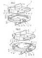
- FIG. 1a perspective exploded view of an intervertebral implant with an upper part, a lower part, and a pivot insert that can be inserted between them;
- FIG. 2a perspective exploded view of the upper part and the lower part of the intervertebral implant, without an inserted pivot insert;
- FIG. 3a view similar to FIG. 2 with the pivot insert inserted into the lower part;
- FIG. 4a perspective view of the upper part and the lower part of the intervertebral implant with maximum mutual proximity;
- FIG. 5a front view of the intervertebral implant of FIG. 4 ;
- FIG. 6a perspective view of the intervertebral implant with the pivot insert inserted.
- FIG. 7a cross-sectional view of the intervertebral implant of FIG. 6 .
- the intervertebral implant 1 shown in the drawingincludes three parts, namely a platelike upper part 2 , a platelike lower part 3 , and a substantially platelike pivot insert 4 .
- the implantalthough having rounded corners, is generally rectangular.
- the upper part 2is embodied flat on its top, thus creating a support face 5 , on which various kinds of protrusions 6 , 7 are disposed which serve the purpose of anchoring the upper part 2 in a vertebra that rests, with its end face toward an intervertebral space, on the support face 5 .
- the height of each smaller protrusion 7is not greater than its width.
- the upper part 2is substantially rectangular in cross section; in the exemplary embodiment shown, a longitudinal edge 8 curves outward.
- the thickness of the platelike upper part 2is less than in the central region, so that along the short sides of the upper part 2 , downward-pointing recesses 9 each extending parallel to these edges are formed that are open toward the outside.
- the central region of the upper part 2is located between the two recesses 9 and thus has a greater thickness or height and thus forms a downward-pointing protrusion 10 embodied between the two recesses 9 .
- This protrusionis defined by an underside 11 , which extends substantially parallel to the support face 5 and in which there is a spherical indentation 12 , which forms a bearing plate for the pivot insert 4 .
- the lower part 3 of the intervertebral implant 1is also platelike in embodiment and on its underside has a flat support face 13 with protrusions 14 and 15 , which correspond to the protrusions 6 and 7 of the support face 5 .
- the thickness of the lower part 3is less in the central region than in an outer region.
- This outer region of greater thicknesshas the form of a U, with two parallel legs 16 , 17 , which extend parallel to the short edges of the lower part 3 , which in cross section is embodied similarly to the upper part 2 , and with a crosspiece 18 that connects the two legs 16 and 17 on one end.
- the region enclosed by the legs 16 and 17 and the crosspiece 18forms a central indentation 19 , whose area is substantially equivalent to the area of the central protrusion 10 of the upper part 2 , while the disposition and length of the legs 16 and 17 correspond essentially to the disposition and length of the recesses 9 on the upper part 2 .
- the dimensionsare selected such that the various recesses are essentially filled completely by the protrusions dipping into them.
- Blind bores 20 and 21are machined into the two legs 16 and 17 of the lower part 3 , extending parallel to these legs 16 , 17 from their free ends; the diameter of these bores is relatively great in proportion to the height of the legs 16 , 17 , and this diameter is in fact greater than the thickness or height of the lower part 3 in the region of the central indentation 19 .
- Blind bores 22 and 23which extend parallel to the blind bores 20 and 21 in the lower part 3 , are machined into the central protrusion 10 of the upper part 2 , in the vicinity of its side edges. These blind bores 22 and 23 again have a relatively great diameter, which corresponds to a substantial portion of the height of the protrusion 10 and is greater than the thickness of the upper part 2 in the region of the recesses 9 .
- the blind bores 20 and 21 of the lower part 3 and the blind bores 22 and 23 of the upper part 2overlap at least partly in the direction of the height of the intervertebral implant 1 , as is clearly shown in FIGS. 4 and 5 .
- the blind bores 20 , 21 , 22 and 23serve as receptacles for pinlike extensions of a manipulation instrument, not shown in the drawing, and thus form engagement elements for this manipulation instrument, which in this way separately engages the upper part 2 and the lower part 3 .
- this manipulation instrumentit is possible to introduce the upper part 2 and the lower part 3 of the intervertebral implant 1 into an intervertebral space; the very low structural height of the intervertebral implant 1 facilitates this introduction, which can be done essentially without major widening of the intervertebral space.
- the two parts of the intervertebral implant 1can be spread apart; that is, their spacing is increased, for instance with the aid of the manipulation instrument that is holding the upper 2 and the lower part 3 .
- the upper and lower partsor the first and second parts
- these partsare first inserted together into the intervertebral space, after which these parts are separated from each other and the insert is inserted between them. Thereafter, these parts are allowed to come together towards each other to engage the insert.
- This pivot insertis constructed essentially in the shape of a plate, which has a flat underside 24 and a spherically upward-curved top side 25 .
- the outer dimensions of the platelike pivot insertcorrespond to those of the central indentation 19 in the lower part 3 , so that the pivot insert 4 can be thrust into this indentation, filling it up, specifically from the side toward which the blind bores 20 , 21 , 22 , 23 open.
- Guide strips 26 on the side edges of the pivot insert 4engage corresponding guide grooves 27 in the legs 16 , 17 , so that an insertion guide for the pivot insert 4 is formed that fixes it in the lower part 3 after its insertion.
- the inserted pivot insert 4after insertion, fills up the indentation 19 and protrudes with its spherically curved top side 25 upward past the top side of the lower part 3 ; the spherical top side 25 dips in complimentary fashion into the spherically curved indentation 12 on the underside of the protrusion 10 , where with the upper part 2 it forms a ball joint, which enables a certain pivotability of the upper part 2 relative to the lower part 3 ( FIG. 7 ).
- the pivot insert 4can have a detent protrusion 28 on its flat underside 24 ; when the pivot insert 4 is inserted into the lower part 3 , this protrusion locks elastically into a detent recess 29 that is located on the bottom of the indentation 19 ; as a result, the pivot insert 4 is also fixed in the insertion direction in the indentation 19 .
- the upper part 2 and lower part 3are preferably made of physiologically safe metal, such as titanium, while the pivot insert 4 preferably comprises a likewise physiologically safe plastic material, such as polyethylene.
- physiologically safe metalsuch as titanium
- the pivot insert 4preferably comprises a likewise physiologically safe plastic material, such as polyethylene.
- These support faces 5 and 13can be embodied in an especially bone-compatible way; for instance, this surface can be roughened by a coating, so that optimal anchoring to the adjacent bone material is obtained.
- An upper part 2has an upper surface 5 for engaging a vertebrae and a lower surface which comprises a downward pointing protrusion 10 between side recesses 9 and a rounded portion, preferably in the form of a concave spherical indentation 12 .
- a lower part 3has a lower surface 13 for engaging a vertebrae.
- a pivot insert 4when joined to the lower part 3 , as shown for example in FIG. 3 , provides a convex upper surface portion 25 , preferably spherical, in operational engagement with the rounded portion 12 of the upper part.
- the lower part 3 and pivot insert 4may, taken together, be described as a lower part formed in two pieces, namely the elements 3 and 4 , wherein the element 3 may be referred to as a lower piece and the element 4 may be referred to as an upper piece.
- the upper and lower partsinclude on their upper surface and lower surface, respectively, protrusions 6 and 14 which may also be referred to as anchors, which anchor the upper and lower parts, respectively, into the adjacent vertebrae that form the intervertebral space and rest against the respective upper and lower surfaces.
- the anchors 6 and 14are each single anchors, preferably extending perpendicular to the respective outer surfaces from which they extend.
- the anchorsmay also be referred to as anchor portions and the plane or line along which the anchor or anchor portions extend may be referred to as an anchor line.
- Each of the anchors 6 and 14has a zigzag edge which comprises a series of teeth.
- anchor 6has at least one section that is greater in height than the remainder of the upper part 2 , i.e., from surface 5 to the bottom of protrusion 10 , at the section of the upper part where the anchor section meets the surface of the part.
- anchor 14is greater in height than the remainder of the lower part 3 exclusive of its convex portion, i.e., from lower surface 13 to the top of walls 16 , 17 and 18 .
- anchor 6is aligned along a single anchor line across surface 5 to form a single anchor plane, this anchor plane having an anchor plane height at least a portion of which is greater than the height of the remainder of the upper part 2 at the section of the upper part where the anchor plane portion meets the surface.
- anchor plane heightat least a portion of which is greater than the height of the remainder of the upper part 2 at the section of the upper part where the anchor plane portion meets the surface.
- At least a portion (here, at least the facing portion) of anchor 6is at least substantially equal in height to the overall height of the remainder of the upper part 2 , i.e., from surface 5 to the bottom of protrusion 10 with its longitudinal edge 8 . Furthermore, as can be seen in the perspective view of these same parts shown in FIG. 4 , by virtue of the sloping edge of the anchor 6 at least a portion of the anchor plane height of anchor 6 may be less than the overall height of the remainder of the upper part 2 .
- the length of the anchors 6 and 14i.e., in the direction from the anterior to the posterior thereof, is greater than one half of the overall dimension of its respective part from its anterior to its posterior (as defined with reference to the part's anterior posterior orientation in the body upon implantation), passing through that anchor.
- the vertical height of each anchor 6 and 14is greater than its width which is the dimension taken horizontally in FIG. 5 or 7 .
- the anchors 6 and 14lie essentially in a common vertical plane in the assembled implant. As best shown in FIG.
- pivot insert 4enables a certain pivotability, or articulating motion, of the upper part 2 relative to the lower part 3 .
- Midlinesare lines on the outer surfaces passing essentially through the center of the outer surfaces of parts 2 and 3 . Such midlines may divide the part into two separate symmetrical halves.
- the common vertical plane of anchors 6 and 14is located essentially at a midline of the implant which lies in an anterior to posterior plane of the implant, again as defined with reference to the intended orientation of the implant upon implantation.
- Each anchor 6 and 14is elongated along the anterior to posterior midline and the width of each anchor straddles the midline.
- the lower partcomprises three walls including parallel side walls 16 and 17 and a rear wall 18 . These walls form between them a central indentation 19 which comprises a recess with a generally flat surface. The fourth side of the recess is open.
- the pivot insert 4has a detent 28 that snap-fits into a detent recess 29 formed in the generally flat surface of recess 19 .
- the protrusion 10 of upper part 2can fit down between walls 16 , 17 and 18 of the lower part 2 .
- This fitting of protrusion 10 within the recess 19 , surrounded by walls 16 , 17 and 18may be referred to as “nesting” since the protrusion 10 essentially “nests” within recess 19 .
- the combined height of the upper and lower parts 2 and 3i.e., the height from surface 13 to surface 5
- the total additive height of the upper and lower partstaken separately, i.e., less than the total of the height from surface 13 to the top of walls 16 , 17 and 18 plus the height from surface 5 to the bottom of protrusion 10 .
- the implantTo reach its final destination within an intervertebral space, the implant must of course be moved along a path, i.e., an insertion direction from outside of the patient, into the patient, and then into the intervertebral space.
- instrumentswould engage apertures 20 , 21 , 22 and 23 to move implant along a path in an insertion direction.
- the anchors 6 and 14are parallel to this path and each defines a single anchor line parallel to this path as the implant is moved into an intervertebral space. Each anchor is thus adapted to enter a corresponding groove in the adjacent vertebra as the implant is inserted.
- lateral planes parallel to the direction of this pathpass through the outermost boundaries of the implant which, in the preferred embodiment, would be the opposed side surfaces of the parts.
- Each anchor 6 and 14lies at a midline at the center of the outer surface of each part 2 and 3 in between and parallel to the lateral parallel planes.
- the pathwould be parallel to the front to rear (anterior to posterior) direction, wherein, during insertion, the rear (posterior) of the implant would constitute the lead end and the front (anterior) thereof would constitute the trailing end.
Landscapes
- Health & Medical Sciences (AREA)
- Engineering & Computer Science (AREA)
- Biomedical Technology (AREA)
- Orthopedic Medicine & Surgery (AREA)
- Neurology (AREA)
- Heart & Thoracic Surgery (AREA)
- Oral & Maxillofacial Surgery (AREA)
- Transplantation (AREA)
- Cardiology (AREA)
- Vascular Medicine (AREA)
- Life Sciences & Earth Sciences (AREA)
- Animal Behavior & Ethology (AREA)
- General Health & Medical Sciences (AREA)
- Public Health (AREA)
- Veterinary Medicine (AREA)
- Prostheses (AREA)
Abstract
Description
Claims (10)
Priority Applications (1)
| Application Number | Priority Date | Filing Date | Title |
|---|---|---|---|
| US11/766,182US8795371B2 (en) | 1999-07-02 | 2007-06-21 | Intervertebral implant |
Applications Claiming Priority (5)
| Application Number | Priority Date | Filing Date | Title |
|---|---|---|---|
| PCT/EP1999/004628WO2001001893A1 (en) | 1999-07-02 | 1999-07-02 | Intervertebral implant |
| US10/018,402US6936071B1 (en) | 1999-07-02 | 1999-07-02 | Intervertebral implant |
| DE29911422UDE29911422U1 (en) | 1999-07-02 | 1999-07-02 | Intervertebral implant |
| US10/998,951US8506634B2 (en) | 1999-07-02 | 2004-11-30 | Intervertebral implant |
| US11/766,182US8795371B2 (en) | 1999-07-02 | 2007-06-21 | Intervertebral implant |
Related Parent Applications (1)
| Application Number | Title | Priority Date | Filing Date |
|---|---|---|---|
| US10/998,951ContinuationUS8506634B2 (en) | 1999-07-02 | 2004-11-30 | Intervertebral implant |
Publications (2)
| Publication Number | Publication Date |
|---|---|
| US20070265707A1 US20070265707A1 (en) | 2007-11-15 |
| US8795371B2true US8795371B2 (en) | 2014-08-05 |
Family
ID=26062622
Family Applications (6)
| Application Number | Title | Priority Date | Filing Date |
|---|---|---|---|
| US10/018,402Expired - LifetimeUS6936071B1 (en) | 1999-07-02 | 1999-07-02 | Intervertebral implant |
| US10/998,951Expired - Fee RelatedUS8506634B2 (en) | 1999-07-02 | 2004-11-30 | Intervertebral implant |
| US11/185,781Expired - LifetimeUS8974530B2 (en) | 1999-07-02 | 2005-07-21 | Intervertebral implant |
| US11/766,182Expired - LifetimeUS8795371B2 (en) | 1999-07-02 | 2007-06-21 | Intervertebral implant |
| US13/777,076Expired - Fee RelatedUS8882839B2 (en) | 1999-07-02 | 2013-02-26 | Intervertebral implant |
| US14/605,055Expired - Fee RelatedUS9526624B2 (en) | 1999-07-02 | 2015-01-26 | Intervertebral implant |
Family Applications Before (3)
| Application Number | Title | Priority Date | Filing Date |
|---|---|---|---|
| US10/018,402Expired - LifetimeUS6936071B1 (en) | 1999-07-02 | 1999-07-02 | Intervertebral implant |
| US10/998,951Expired - Fee RelatedUS8506634B2 (en) | 1999-07-02 | 2004-11-30 | Intervertebral implant |
| US11/185,781Expired - LifetimeUS8974530B2 (en) | 1999-07-02 | 2005-07-21 | Intervertebral implant |
Family Applications After (2)
| Application Number | Title | Priority Date | Filing Date |
|---|---|---|---|
| US13/777,076Expired - Fee RelatedUS8882839B2 (en) | 1999-07-02 | 2013-02-26 | Intervertebral implant |
| US14/605,055Expired - Fee RelatedUS9526624B2 (en) | 1999-07-02 | 2015-01-26 | Intervertebral implant |
Country Status (13)
| Country | Link |
|---|---|
| US (6) | US6936071B1 (en) |
| EP (2) | EP1194088B1 (en) |
| JP (1) | JP4192262B2 (en) |
| AR (1) | AR024632A1 (en) |
| AT (1) | ATE388677T1 (en) |
| AU (5) | AU780719B2 (en) |
| BR (1) | BR9917397A (en) |
| CA (1) | CA2391330C (en) |
| DE (3) | DE29924985U1 (en) |
| ES (1) | ES2303381T3 (en) |
| MX (1) | MXPA01013413A (en) |
| NZ (1) | NZ516410A (en) |
| WO (1) | WO2001001893A1 (en) |
Cited By (4)
| Publication number | Priority date | Publication date | Assignee | Title |
|---|---|---|---|---|
| US9526624B2 (en) | 1999-07-02 | 2016-12-27 | DePuy Synthes Products, Inc. | Intervertebral implant |
| US9539110B2 (en) | 2011-01-06 | 2017-01-10 | Darren L. BERGEY | Interbody prosthetic device with compound-arc, blade anchor |
| US9883950B2 (en) | 2006-07-24 | 2018-02-06 | Centinel Spine Llc | Intervertebral implant with keel |
| US11701238B2 (en) | 2011-01-06 | 2023-07-18 | Darren L. BERGEY | Compressive, orthopedic, anchoring apparatus and method |
Families Citing this family (297)
| Publication number | Priority date | Publication date | Assignee | Title |
|---|---|---|---|---|
| US20080039859A1 (en)* | 1997-01-02 | 2008-02-14 | Zucherman James F | Spine distraction implant and method |
| FR2897259B1 (en) | 2006-02-15 | 2008-05-09 | Ldr Medical Soc Par Actions Si | INTERSOMATIC TRANSFORAMINAL CAGE WITH INTERBREBAL FUSION GRAFT AND CAGE IMPLANTATION INSTRUMENT |
| EP1792586B1 (en) | 1999-09-14 | 2012-12-26 | Spine Solutions Inc. | Insert instrument for an implant between vertebrae |
| US8940047B2 (en) | 2001-02-15 | 2015-01-27 | Spinecore, Inc. | Intervertebral spacer device having recessed notch pairs for manipulation using a surgical tool |
| US6673113B2 (en) | 2001-10-18 | 2004-01-06 | Spinecore, Inc. | Intervertebral spacer device having arch shaped spring elements |
| US7223291B2 (en) | 2001-07-16 | 2007-05-29 | Spinecore, Inc. | Intervertebral spacer device having engagement hole pairs for manipulation using a surgical tool |
| FR2824261B1 (en) | 2001-05-04 | 2004-05-28 | Ldr Medical | INTERVERTEBRAL DISC PROSTHESIS AND IMPLEMENTATION METHOD AND TOOLS |
| FR2827156B1 (en) | 2001-07-13 | 2003-11-14 | Ldr Medical | VERTEBRAL CAGE DEVICE WITH MODULAR FASTENING |
| WO2003032802A2 (en)* | 2001-10-18 | 2003-04-24 | Third Millennium Engineering Llc | Intervertebral spacer device having an arched spring element |
| FR2831048B1 (en) | 2001-10-18 | 2004-09-17 | Ldr Medical | PROGRESSIVE APPROACH OSTEOSYNTHESIS DEVICE AND PRE-ASSEMBLY PROCESS |
| FR2831049B1 (en)* | 2001-10-18 | 2004-08-13 | Ldr Medical | PLATE FOR OSTEOSYNTHESIS DEVICE AND PRE-ASSEMBLY METHOD |
| US6740118B2 (en)* | 2002-01-09 | 2004-05-25 | Sdgi Holdings, Inc. | Intervertebral prosthetic joint |
| US7708776B1 (en)* | 2002-01-16 | 2010-05-04 | Nuvasive, Inc. | Intervertebral disk replacement system and methods |
| EP1482877B1 (en)* | 2002-03-11 | 2007-05-30 | Spinal Concepts Inc. | Instrumentation for implanting spinal implant devices |
| EP1344507A1 (en)* | 2002-03-12 | 2003-09-17 | Waldemar Link (GmbH & Co.) | Intervertebral prosthesis for the cervical spine |
| RU2303422C2 (en) | 2002-03-12 | 2007-07-27 | Сервитек Инк. | Intervertebral prosthesis and system of intervertebral prostheses, in peculiar case, for cervical department of vertebral column |
| DE50210270D1 (en) | 2002-03-12 | 2007-07-19 | Cervitech Inc | Intervertebral prosthesis, especially for the cervical spine |
| ES2322446T3 (en) | 2002-03-12 | 2009-06-22 | Cervitech Inc. | INTERVERTEBRAL PROTESIS. |
| US6824278B2 (en)* | 2002-03-15 | 2004-11-30 | Memx, Inc. | Self-shadowing MEM structures |
| US7717959B2 (en)* | 2002-03-30 | 2010-05-18 | Lytton William | Intervertebral device and method of use |
| CN1304618C (en)* | 2002-04-05 | 2007-03-14 | 新日本制铁株式会社 | Pealite based rail excellent in wear resistance and ductility and method for production thereof |
| US8038713B2 (en) | 2002-04-23 | 2011-10-18 | Spinecore, Inc. | Two-component artificial disc replacements |
| US20080027548A9 (en) | 2002-04-12 | 2008-01-31 | Ferree Bret A | Spacerless artificial disc replacements |
| US20030233097A1 (en)* | 2002-04-23 | 2003-12-18 | Ferree Bret A. | Artificial disc replacement (ADR) distraction sleeves and cutting guides |
| US6706068B2 (en) | 2002-04-23 | 2004-03-16 | Bret A. Ferree | Artificial disc replacements with natural kinematics |
| US20040030390A1 (en)* | 2002-04-23 | 2004-02-12 | Ferree Bret A. | Intradiscal component installation apparatus and methods |
| US7179294B2 (en) | 2002-04-25 | 2007-02-20 | Warsaw Orthopedic, Inc. | Articular disc prosthesis and method for implanting the same |
| US7001433B2 (en) | 2002-05-23 | 2006-02-21 | Pioneer Laboratories, Inc. | Artificial intervertebral disc device |
| US8388684B2 (en) | 2002-05-23 | 2013-03-05 | Pioneer Signal Technology, Inc. | Artificial disc device |
| GB2389046B (en)* | 2002-05-27 | 2005-10-05 | Biomet Merck Ltd | Spinal prosthesis |
| US6793678B2 (en) | 2002-06-27 | 2004-09-21 | Depuy Acromed, Inc. | Prosthetic intervertebral motion disc having dampening |
| EP1542626B1 (en) | 2002-08-15 | 2012-09-26 | Synthes GmbH | Controlled artificial intervertebral disc implant |
| CA2495404C (en) | 2002-08-15 | 2011-05-03 | Justin K. Coppes | Intervertebral disc implant |
| DE10242331B4 (en) | 2002-09-12 | 2005-10-20 | Biedermann Motech Gmbh | Placeholder for vertebral bodies or intervertebral discs |
| DE10242329B4 (en)* | 2002-09-12 | 2005-03-17 | Biedermann Motech Gmbh | Disc prosthesis |
| US7537614B2 (en) | 2002-09-18 | 2009-05-26 | Synthes Usa, Llc | Implant comprising a two-piece joint |
| AU2003226586A1 (en)* | 2002-09-19 | 2004-04-08 | Malan De Villiers | Intervertebral prosthesis |
| US7273496B2 (en) | 2002-10-29 | 2007-09-25 | St. Francis Medical Technologies, Inc. | Artificial vertebral disk replacement implant with crossbar spacer and method |
| JP4654125B2 (en) | 2002-10-29 | 2011-03-16 | スパインコア,インコーポレイテッド | Instruments, methods, and functions for use in implanting an artificial disc |
| US6966929B2 (en) | 2002-10-29 | 2005-11-22 | St. Francis Medical Technologies, Inc. | Artificial vertebral disk replacement implant with a spacer |
| US7833246B2 (en)* | 2002-10-29 | 2010-11-16 | Kyphon SÀRL | Interspinous process and sacrum implant and method |
| US7083649B2 (en) | 2002-10-29 | 2006-08-01 | St. Francis Medical Technologies, Inc. | Artificial vertebral disk replacement implant with translating pivot point |
| US7497859B2 (en) | 2002-10-29 | 2009-03-03 | Kyphon Sarl | Tools for implanting an artificial vertebral disk |
| AU2003287370B2 (en)* | 2002-10-31 | 2009-05-07 | Zimmer Spine, Inc. | Movable disc implant |
| FR2846550B1 (en)* | 2002-11-05 | 2006-01-13 | Ldr Medical | INTERVERTEBRAL DISC PROSTHESIS |
| EP1417940A1 (en) | 2002-11-08 | 2004-05-12 | Waldemar Link (GmbH & Co.) | Vertebral prosthesis |
| US20040098129A1 (en)* | 2002-11-13 | 2004-05-20 | Jo-Wen Lin | Spinal implant insertion adjustment instrument and implants for use therewith |
| US7204852B2 (en) | 2002-12-13 | 2007-04-17 | Spine Solutions, Inc. | Intervertebral implant, insertion tool and method of inserting same |
| GB0301085D0 (en)* | 2003-01-17 | 2003-02-19 | Krishna Manoj | Articulating spinal disc prosthesis |
| US20040186577A1 (en)* | 2003-01-29 | 2004-09-23 | Ferree Bret A. | In situ artificaial disc replacements and other prosthetic components |
| WO2004066884A1 (en) | 2003-01-31 | 2004-08-12 | Spinalmotion, Inc. | Intervertebral prosthesis placement instrument |
| ZA200506029B (en)* | 2003-01-31 | 2006-10-25 | Spinalmotion Inc | Spinal Midline Indicator |
| US20040158254A1 (en)* | 2003-02-12 | 2004-08-12 | Sdgi Holdings, Inc. | Instrument and method for milling a path into bone |
| US7235101B2 (en)* | 2003-09-15 | 2007-06-26 | Warsaw Orthopedic, Inc. | Revisable prosthetic device |
| AU2004212942A1 (en) | 2003-02-14 | 2004-09-02 | Depuy Spine, Inc. | In-situ formed intervertebral fusion device |
| US6908484B2 (en) | 2003-03-06 | 2005-06-21 | Spinecore, Inc. | Cervical disc replacement |
| EP1610740A4 (en) | 2003-04-04 | 2009-04-08 | Theken Disc Llc | Artificial disc prosthesis |
| BRPI0409091A (en)* | 2003-04-07 | 2006-04-11 | Cervitech Inc | intervertebral joint prosthesis for the cervical spine |
| US8012212B2 (en) | 2003-04-07 | 2011-09-06 | Nuvasive, Inc. | Cervical intervertebral disk prosthesis |
| CN100484499C (en)* | 2003-04-14 | 2009-05-06 | 斯恩蒂斯有限公司 | Intervertebral implant |
| US7491204B2 (en) | 2003-04-28 | 2009-02-17 | Spine Solutions, Inc. | Instruments and method for preparing an intervertebral space for receiving an artificial disc implant |
| US7291173B2 (en) | 2003-05-06 | 2007-11-06 | Aesculap Ii, Inc. | Artificial intervertebral disc |
| US7105024B2 (en) | 2003-05-06 | 2006-09-12 | Aesculap Ii, Inc. | Artificial intervertebral disc |
| EP1514527A3 (en)* | 2003-05-06 | 2005-10-26 | Spinal Innovations, LLC | Artificial intervertebral disc |
| DE20307876U1 (en)* | 2003-05-19 | 2004-09-23 | Metz-Stavenhagen, Peter, Dr.med. | Device for implantation in a human or animal spine |
| DE10324108B3 (en)* | 2003-05-21 | 2005-01-27 | Aesculap Ag & Co. Kg | Backbone implant is inserted with contracted contact disc which is expanded to optimum area following insertion |
| US7575599B2 (en) | 2004-07-30 | 2009-08-18 | Spinalmotion, Inc. | Intervertebral prosthetic disc with metallic core |
| US7442211B2 (en) | 2003-05-27 | 2008-10-28 | Spinalmotion, Inc. | Intervertebral prosthetic disc |
| US20090076614A1 (en)* | 2007-09-17 | 2009-03-19 | Spinalmotion, Inc. | Intervertebral Prosthetic Disc with Shock Absorption Core |
| US10052211B2 (en) | 2003-05-27 | 2018-08-21 | Simplify Medical Pty Ltd. | Prosthetic disc for intervertebral insertion |
| US20040267367A1 (en) | 2003-06-30 | 2004-12-30 | Depuy Acromed, Inc | Intervertebral implant with conformable endplate |
| DE10330698B4 (en) | 2003-07-08 | 2005-05-25 | Aesculap Ag & Co. Kg | Intervertebral implant |
| DE20310433U1 (en) | 2003-07-08 | 2003-09-04 | Aesculap AG & Co. KG, 78532 Tuttlingen | Surgical device for inserting dual component implant into appropriate space at spine, comprising particularly shaped holding area |
| US7320689B2 (en)* | 2003-07-15 | 2008-01-22 | Cervitech, Inc. | Multi-part cervical endoprosthesis with insertion instrument |
| US7803162B2 (en) | 2003-07-21 | 2010-09-28 | Spine Solutions, Inc. | Instruments and method for inserting an intervertebral implant |
| EP1512384A1 (en)* | 2003-07-21 | 2005-03-09 | Cervitech, Inc. | Intervertebral disc prosthesis |
| EP1646336B1 (en) | 2003-07-22 | 2009-07-08 | Synthes GmbH | Intervertebral implant comprising dome-shaped joint surfaces |
| CN100566677C (en)* | 2003-07-22 | 2009-12-09 | 斯恩蒂斯有限公司 | The intraarticular prosthese |
| US7153325B2 (en)* | 2003-08-01 | 2006-12-26 | Ultra-Kinetics, Inc. | Prosthetic intervertebral disc and methods for using the same |
| FR2858546B1 (en) | 2003-08-04 | 2006-04-28 | Spine Next Sa | INTERVERTEBRAL DISC PROSTHESIS |
| US7753958B2 (en) | 2003-08-05 | 2010-07-13 | Gordon Charles R | Expandable intervertebral implant |
| DE10339170B4 (en)* | 2003-08-22 | 2009-10-15 | Aesculap Ag | Intervertebral implant |
| US7794465B2 (en)* | 2003-09-10 | 2010-09-14 | Warsaw Orthopedic, Inc. | Artificial spinal discs and associated implantation instruments and methods |
| DE20315611U1 (en)* | 2003-10-08 | 2003-12-11 | Aesculap Ag & Co. Kg | Intervertebral implant |
| DE20315613U1 (en)* | 2003-10-08 | 2003-12-11 | Aesculap Ag & Co. Kg | Intervertebral implant |
| JP4695717B2 (en)* | 2003-11-03 | 2011-06-08 | イシュラップ インプラント システムズ, インコーポレイテッド | Artificial disc |
| US7520899B2 (en) | 2003-11-05 | 2009-04-21 | Kyphon Sarl | Laterally insertable artificial vertebral disk replacement implant with crossbar spacer |
| EP1532948B1 (en)* | 2003-11-18 | 2006-06-21 | Zimmer GmbH | Surgical system for insertion of spinal disc prostheses |
| EP1532950B1 (en)* | 2003-11-18 | 2008-03-26 | Zimmer GmbH | Spinal disc prosthesis |
| US7837732B2 (en) | 2003-11-20 | 2010-11-23 | Warsaw Orthopedic, Inc. | Intervertebral body fusion cage with keels and implantation methods |
| US7670377B2 (en) | 2003-11-21 | 2010-03-02 | Kyphon Sarl | Laterally insertable artifical vertebral disk replacement implant with curved spacer |
| FR2862866B1 (en)* | 2003-11-28 | 2006-12-15 | Gilles Voydeville | POSTERO-LATERAL INTERVERTEBRAL DISCSTRATE |
| US20050154462A1 (en)* | 2003-12-02 | 2005-07-14 | St. Francis Medical Technologies, Inc. | Laterally insertable artificial vertebral disk replacement implant with translating pivot point |
| US7481839B2 (en) | 2003-12-02 | 2009-01-27 | Kyphon Sarl | Bioresorbable interspinous process implant for use with intervertebral disk remediation or replacement implants and procedures |
| US7217291B2 (en) | 2003-12-08 | 2007-05-15 | St. Francis Medical Technologies, Inc. | System and method for replacing degenerated spinal disks |
| DE10361166A1 (en)* | 2003-12-22 | 2005-07-28 | Meisel, Jörg, Dr. | Component for a prosthesis, especially a cervica vertebra, comprises two base parts coupled together by a hinge |
| DE10361957B4 (en)* | 2003-12-23 | 2006-03-02 | Eska Implants Gmbh & Co. | cervical spine implant |
| US20050165407A1 (en)* | 2004-01-23 | 2005-07-28 | Diaz Robert L. | Disk arthroplasty instrumentation and implants |
| GB2410189A (en)* | 2004-01-23 | 2005-07-27 | Corin Ltd | Intervertebral disc prosthesis |
| FR2865629B1 (en) | 2004-02-04 | 2007-01-26 | Ldr Medical | INTERVERTEBRAL DISC PROSTHESIS |
| EP2113227B1 (en) | 2004-02-04 | 2015-07-29 | LDR Medical | Intervertebral disc prosthesis |
| US7195644B2 (en)* | 2004-03-02 | 2007-03-27 | Joint Synergy, Llc | Ball and dual socket joint |
| US7491239B2 (en) | 2005-02-23 | 2009-02-17 | Joint Synergy, Llc | Interior insert ball and dual socket joint |
| US20050209693A1 (en)* | 2004-03-02 | 2005-09-22 | Janzen Lo | Spinal implants |
| US8636802B2 (en) | 2004-03-06 | 2014-01-28 | DePuy Synthes Products, LLC | Dynamized interspinal implant |
| FR2869528B1 (en)* | 2004-04-28 | 2007-02-02 | Ldr Medical | INTERVERTEBRAL DISC PROSTHESIS |
| US20050251261A1 (en)* | 2004-05-05 | 2005-11-10 | Sdgi Holdings, Inc. | Artificial intervertebral disc for lateral insertion |
| US7500972B2 (en)* | 2004-05-07 | 2009-03-10 | Ethicon Endo-Surgery, Inc. | Device for alternately holding, or effecting relative longitudinal movement, of members of a medical instrument |
| DE202004009542U1 (en)* | 2004-06-16 | 2004-08-12 | Aesculap Ag & Co. Kg | Artificial intervertebral disk, comprising core with intensely curved upper and less curved lower surface |
| US9237958B2 (en) | 2004-06-30 | 2016-01-19 | Synergy Disc Replacement Inc. | Joint prostheses |
| US8172904B2 (en)* | 2004-06-30 | 2012-05-08 | Synergy Disc Replacement, Inc. | Artificial spinal disc |
| MXPA06014714A (en)* | 2004-06-30 | 2007-06-22 | Synergy Disc Replacement Inc | Artificial spinal disc. |
| US8454699B2 (en)* | 2004-06-30 | 2013-06-04 | Synergy Disc Replacement, Inc | Systems and methods for vertebral disc replacement |
| US7585326B2 (en) | 2004-08-06 | 2009-09-08 | Spinalmotion, Inc. | Methods and apparatus for intervertebral disc prosthesis insertion |
| US7854752B2 (en) | 2004-08-09 | 2010-12-21 | Theken Spine, Llc | System and method for dynamic skeletal stabilization |
| PL1857079T3 (en)* | 2004-09-08 | 2010-01-29 | Synthes Gmbh | Universal intervertebral disc prosthesis |
| US7763024B2 (en)* | 2004-09-23 | 2010-07-27 | Spine Solutions, Inc. | Adjustable cutting of cutout in vertebral bone |
| US7547309B2 (en) | 2004-09-23 | 2009-06-16 | Spine Solutions, Inc. | Distractor for lumbar insertion instrument |
| KR20120102806A (en)* | 2004-09-23 | 2012-09-18 | 스파인 소루션 아이앤씨 | System and method for an intervertebral implant |
| US20060069441A1 (en)* | 2004-09-29 | 2006-03-30 | Zucherman James F | Posterior approach implant method for assembly of multi-piece artificial spinal disk replacement device in situ |
| US7575600B2 (en) | 2004-09-29 | 2009-08-18 | Kyphon Sarl | Artificial vertebral disk replacement implant with translating articulation contact surface and method |
| US7481840B2 (en) | 2004-09-29 | 2009-01-27 | Kyphon Sarl | Multi-piece artificial spinal disk replacement device with selectably positioning articulating element |
| US7582115B2 (en)* | 2004-09-30 | 2009-09-01 | Helmut Weber | Intervertebral prosthesis |
| US20060085076A1 (en)* | 2004-10-15 | 2006-04-20 | Manoj Krishna | Posterior spinal arthroplasty-development of a new posteriorly inserted artificial disc and an artificial facet joint |
| WO2006042485A1 (en)* | 2004-10-18 | 2006-04-27 | Buettner-Janz Karin | Intervertebral disk endoprosthesis for lumbar and cervical spine, which corresponds to the physiology of movement |
| USD598105S1 (en) | 2004-10-21 | 2009-08-11 | Disc Motion Technologies, Inc. | Convex intervertebral disc prosthesis |
| USD597674S1 (en) | 2004-10-21 | 2009-08-04 | Disc Motion Technologies, Inc. | Concave intervertebral disc prosthesis |
| US20060265074A1 (en) | 2004-10-21 | 2006-11-23 | Manoj Krishna | Posterior spinal arthroplasty-development of a new posteriorly inserted artificial disc, a new anteriorly inserted artifical disc and an artificial facet joint |
| WO2006058221A2 (en) | 2004-11-24 | 2006-06-01 | Abdou Samy M | Devices and methods for inter-vertebral orthopedic device placement |
| DE102004059298B3 (en)* | 2004-12-09 | 2006-07-13 | Aesculap Ag & Co. Kg | Kit for an intervertebral implant and intervertebral implant |
| US20060149371A1 (en)* | 2004-12-10 | 2006-07-06 | Sdgi Holdings, Inc. | Intervertebral prosthetic device and method with locking mechanism |
| FR2879436B1 (en) | 2004-12-22 | 2007-03-09 | Ldr Medical | INTERVERTEBRAL DISC PROSTHESIS |
| CH697330B1 (en) | 2004-12-28 | 2008-08-29 | Synthes Gmbh | Intervertebral prosthesis. |
| US8083797B2 (en) | 2005-02-04 | 2011-12-27 | Spinalmotion, Inc. | Intervertebral prosthetic disc with shock absorption |
| ATE531346T1 (en)* | 2005-02-24 | 2011-11-15 | Morphogeny Llc | CONNECTED, SLIDING AND MATCHABLE ROTATABLE COMPONENTS |
| US8496686B2 (en)* | 2005-03-22 | 2013-07-30 | Gmedelaware 2 Llc | Minimally invasive spine restoration systems, devices, methods and kits |
| US8777959B2 (en) | 2005-05-27 | 2014-07-15 | Spinecore, Inc. | Intervertebral disc and insertion methods therefor |
| US8394142B2 (en)* | 2005-06-13 | 2013-03-12 | Synthes Usa, Llc | Customizing an intervertebral implant |
| EP1736120A1 (en) | 2005-06-22 | 2006-12-27 | Cervitech, Inc. | Intervertebral prosthesis with self-cutting fixation protrusions |
| FR2887435B1 (en)* | 2005-06-24 | 2007-10-05 | Abbott Spine Sa | INTERVERTEBRAL DISC PROSTHESIS |
| FR2887762B1 (en) | 2005-06-29 | 2007-10-12 | Ldr Medical Soc Par Actions Si | INTERVERTEBRAL DISC PROSTHESIS INSERTION INSTRUMENTATION BETWEEN VERTEBRATES |
| US8152850B2 (en)* | 2005-07-06 | 2012-04-10 | Spontech Spine Intelligence Group Ag | Intervertebral disc prosthesis |
| US8585764B2 (en) | 2005-07-06 | 2013-11-19 | Spontech Spine Intelligence Group Ag | Intervertebral disc prosthesis manufacturing method |
| FR2891135B1 (en) | 2005-09-23 | 2008-09-12 | Ldr Medical Sarl | INTERVERTEBRAL DISC PROSTHESIS |
| US7867237B2 (en)* | 2005-10-31 | 2011-01-11 | Depuy Spine, Inc. | Arthroplasty revision device and method |
| US7927373B2 (en)* | 2005-10-31 | 2011-04-19 | Depuy Spine, Inc. | Intervertebral disc prosthesis |
| FR2893838B1 (en)* | 2005-11-30 | 2008-08-08 | Ldr Medical Soc Par Actions Si | PROSTHESIS OF INTERVERTEBRAL DISC AND INSTRUMENTATION OF INSERTION OF THE PROSTHESIS BETWEEN VERTEBRATES |
| US8603171B2 (en)* | 2006-01-25 | 2013-12-10 | Mimedx Group, Inc. | Spinal disc implants with flexible keels and methods of fabricating implants |
| US7708777B2 (en)* | 2006-02-03 | 2010-05-04 | Depuy Spine, Inc. | Modular intervertebral disc replacements |
| US8066774B2 (en) | 2006-04-07 | 2011-11-29 | Warsaw Orthopedic, Inc. | Artificial disc implants and associated methods and instrumentation |
| WO2007121320A2 (en) | 2006-04-12 | 2007-10-25 | Spinalmotion, Inc. | Posterior spinal device and method |
| US20080071379A1 (en)* | 2006-05-10 | 2008-03-20 | Mark Rydell | Intervertebral disc replacement |
| US7905906B2 (en)* | 2006-06-08 | 2011-03-15 | Disc Motion Technologies, Inc. | System and method for lumbar arthroplasty |
| US7731752B2 (en)* | 2006-07-21 | 2010-06-08 | Warsaw Orthopedic, Inc. | Implant with nested members and methods of use |
| US20080051901A1 (en) | 2006-07-28 | 2008-02-28 | Spinalmotion, Inc. | Spinal Prosthesis with Multiple Pillar Anchors |
| US20080051900A1 (en)* | 2006-07-28 | 2008-02-28 | Spinalmotion, Inc. | Spinal Prosthesis with Offset Anchors |
| BRPI0714955A2 (en) | 2006-07-31 | 2013-07-23 | Systhes Gmbh | instrument system and method for preparing an intervertebral space to receive an implant, and milling guide for use with an instrument system |
| US7976550B2 (en)* | 2006-08-10 | 2011-07-12 | Pioneer Surgical Technology | Insertion instrument for artificial discs |
| US8409213B2 (en)* | 2006-08-10 | 2013-04-02 | Pioneer Surgical Technology, Inc. | Insertion instrument for artificial discs |
| US8118872B2 (en) | 2006-08-10 | 2012-02-21 | Pioneer Surgical Technology, Inc. | System and methods for inserting a spinal disc device into an intervertebral space |
| US8906096B2 (en) | 2006-08-15 | 2014-12-09 | GMFDelaware 2 LLC | Spinal implant |
| DE602006021239D1 (en)* | 2006-08-22 | 2011-05-19 | Synthes Gmbh | DEVICE FOR RIBBED TOTAL HEADSET |
| US8057545B2 (en) | 2006-08-25 | 2011-11-15 | Warsaw Orthopedic, Inc. | Revision spacer |
| US8414616B2 (en)* | 2006-09-12 | 2013-04-09 | Pioneer Surgical Technology, Inc. | Mounting devices for fixation devices and insertion instruments used therewith |
| US8715350B2 (en) | 2006-09-15 | 2014-05-06 | Pioneer Surgical Technology, Inc. | Systems and methods for securing an implant in intervertebral space |
| WO2008034140A2 (en)* | 2006-09-15 | 2008-03-20 | Pioneer Surgical Technology, Inc. | Systems and methods for sizing, inserting and securing an implant intervertebral space |
| US8377133B2 (en) | 2006-09-15 | 2013-02-19 | Pioneer Surgical Technology, Inc. | Systems and methods for sizing, inserting and securing an implant in intervertebral space |
| WO2008034135A2 (en) | 2006-09-15 | 2008-03-20 | Pioneer Surgical Technology, Inc. | Joint arthroplasty devices having articulating members |
| US8372084B2 (en)* | 2006-09-22 | 2013-02-12 | Pioneer Surgical Technology, Inc. | System and methods for inserting a spinal disc device into an intervertebral space |
| US20080114453A1 (en)* | 2006-11-13 | 2008-05-15 | Warsaw Orthopedic, Inc. | Intervertebral prosthetic devices and surgical methods |
| US8092534B2 (en) | 2006-11-16 | 2012-01-10 | Warsaw Orthopedic, Inc. | Revision device |
| WO2008070863A2 (en) | 2006-12-07 | 2008-06-12 | Interventional Spine, Inc. | Intervertebral implant |
| US20080140204A1 (en)* | 2006-12-07 | 2008-06-12 | Warsaw Orthopedic, Inc. | Vertebral Implant Systems and Methods of Use |
| US9867640B2 (en) | 2006-12-07 | 2018-01-16 | Nexus Spine, LLC | Press-on pedicle screw assembly |
| US8715352B2 (en) | 2006-12-14 | 2014-05-06 | Depuy Spine, Inc. | Buckling disc replacement |
| US20080154378A1 (en)* | 2006-12-22 | 2008-06-26 | Warsaw Orthopedic, Inc. | Bone implant having engineered surfaces |
| US20080161932A1 (en)* | 2006-12-27 | 2008-07-03 | Kevin Armstrong | Artificial Disc |
| US20080161921A1 (en)* | 2006-12-29 | 2008-07-03 | Warsaw Orthopedic, Inc. | Spinal Prosthesis Systems |
| WO2008088777A2 (en) | 2007-01-12 | 2008-07-24 | Synthes Usa, Llc | Modular intervertebral implant |
| US7959677B2 (en) | 2007-01-19 | 2011-06-14 | Flexuspine, Inc. | Artificial functional spinal unit system and method for use |
| US8034081B2 (en) | 2007-02-06 | 2011-10-11 | CollabComl, LLC | Interspinous dynamic stabilization implant and method of implanting |
| US8308801B2 (en)* | 2007-02-12 | 2012-11-13 | Brigham Young University | Spinal implant |
| US9314346B2 (en)* | 2007-02-12 | 2016-04-19 | Brigham Young University | Spinal implant |
| US9138263B2 (en)* | 2007-02-14 | 2015-09-22 | William R. Krause | Flexible spine components |
| US8465546B2 (en) | 2007-02-16 | 2013-06-18 | Ldr Medical | Intervertebral disc prosthesis insertion assemblies |
| US20080228276A1 (en)* | 2007-03-14 | 2008-09-18 | Warsaw Orthopedic, Inc. | Intervertebral Prosthesis, Instruments, and Methods of Implanting |
| US20080228275A1 (en)* | 2007-03-14 | 2008-09-18 | Heather Cannon | Intervertebral implant component with three points of contact |
| DE102007024262B4 (en) | 2007-05-23 | 2017-01-26 | Janos Borgulya | Intervertebral disc prosthesis and instrument cluster with a disc prosthesis |
| FR2916956B1 (en) | 2007-06-08 | 2012-12-14 | Ldr Medical | INTERSOMATIC CAGE, INTERVERTEBRAL PROSTHESIS, ANCHORING DEVICE AND IMPLANTATION INSTRUMENTATION |
| US10821003B2 (en) | 2007-06-20 | 2020-11-03 | 3Spline Sezc | Spinal osteotomy |
| US8900307B2 (en) | 2007-06-26 | 2014-12-02 | DePuy Synthes Products, LLC | Highly lordosed fusion cage |
| US20090043391A1 (en) | 2007-08-09 | 2009-02-12 | Spinalmotion, Inc. | Customized Intervertebral Prosthetic Disc with Shock Absorption |
| US8231676B2 (en)* | 2007-09-17 | 2012-07-31 | Pioneer Surgical Technology, Inc. | Motion preserving artificial intervertebral disc device |
| US20090105834A1 (en) | 2007-10-22 | 2009-04-23 | Spinalmotion, Inc. | Dynamic Spacer Device and Method for Spanning a Space Formed upon Removal of an Intervertebral Disc |
| US8888850B2 (en)* | 2007-11-19 | 2014-11-18 | Linares Medical Devices, Llc | Combination spacer insert and support for providing inter-cervical vertebral support |
| US20090131984A1 (en)* | 2007-11-19 | 2009-05-21 | Linares Miguel A | Spine support implant including inter vertebral insertable fluid ballastable insert and inter-vertebral web retaining harnesses |
| US8758439B2 (en) | 2007-11-19 | 2014-06-24 | Linares Medical Devices, Llc | Spine support implant including inter vertebral insertable fluid ballastable insert and inter-vertebral web retaining harnesses |
| US8894687B2 (en) | 2011-04-25 | 2014-11-25 | Nexus Spine, L.L.C. | Coupling system for surgical construct |
| US8118873B2 (en)* | 2008-01-16 | 2012-02-21 | Warsaw Orthopedic, Inc. | Total joint replacement |
| EP2237748B1 (en) | 2008-01-17 | 2012-09-05 | Synthes GmbH | An expandable intervertebral implant |
| AU2009205679B2 (en) | 2008-01-18 | 2013-12-05 | Spinecore, Inc. | Instruments and methods for inserting artificial intervertebral implants |
| US8764833B2 (en) | 2008-03-11 | 2014-07-01 | Spinalmotion, Inc. | Artificial intervertebral disc with lower height |
| US20090248161A1 (en)* | 2008-03-20 | 2009-10-01 | K2M, Inc. | Artificial disc replacement device |
| US8936641B2 (en) | 2008-04-05 | 2015-01-20 | DePuy Synthes Products, LLC | Expandable intervertebral implant |
| US9034038B2 (en) | 2008-04-11 | 2015-05-19 | Spinalmotion, Inc. | Motion limiting insert for an artificial intervertebral disc |
| EP2278941A1 (en) | 2008-05-05 | 2011-02-02 | Spinalmotion Inc. | Polyaryletherketone artificial intervertebral disc |
| US9220603B2 (en) | 2008-07-02 | 2015-12-29 | Simplify Medical, Inc. | Limited motion prosthetic intervertebral disc |
| DE102009027371A1 (en)* | 2008-07-03 | 2010-01-07 | Ceramtec Ag | intervertebral disc prosthesis |
| EP2299944A4 (en) | 2008-07-17 | 2013-07-31 | Spinalmotion Inc | SYSTEM FOR INSTALLING ARTIFICIAL INTERVERTEBRAL DISCS |
| EP2299941A1 (en) | 2008-07-18 | 2011-03-30 | Spinalmotion Inc. | Posterior prosthetic intervertebral disc |
| DE102008048739A1 (en)* | 2008-09-24 | 2010-04-01 | Franz Dr. Copf jun. | Disc prosthesis |
| US8545566B2 (en) | 2008-10-13 | 2013-10-01 | Globus Medical, Inc. | Articulating spacer |
| US8147554B2 (en) | 2008-10-13 | 2012-04-03 | Globus Medical, Inc. | Intervertebral spacer |
| EP2355751A4 (en)* | 2008-11-14 | 2013-07-10 | David Krueger | Spinal fusion device |
| WO2010075195A1 (en) | 2008-12-22 | 2010-07-01 | Synthes Usa, Llc | Orthopedic implant with flexible keel |
| US20100158209A1 (en)* | 2008-12-22 | 2010-06-24 | General Instrument Corporation | Access to Network Based on Automatic Speech-Recognition |
| CA2743721A1 (en)* | 2009-02-19 | 2010-08-26 | Anton E. Bowden | Compliant dynamic spinal implant |
| WO2010096829A2 (en)* | 2009-02-23 | 2010-08-26 | Crocker Spinal, L.L.C. | Press-on link for surgical screws |
| US9526620B2 (en) | 2009-03-30 | 2016-12-27 | DePuy Synthes Products, Inc. | Zero profile spinal fusion cage |
| US8500801B2 (en) | 2009-04-21 | 2013-08-06 | Medtronic, Inc. | Stents for prosthetic heart valves and methods of making same |
| US20110040331A1 (en)* | 2009-05-20 | 2011-02-17 | Jose Fernandez | Posterior stabilizer |
| KR101687435B1 (en) | 2009-07-06 | 2016-12-19 | 신세스 게엠바하 | Expandable fixation assemblies |
| CN105326585B (en) | 2009-09-17 | 2018-12-11 | Ldr控股公司 | Intervertebral implant with extensible bone anchoring element |
| US9157497B1 (en) | 2009-10-30 | 2015-10-13 | Brigham Young University | Lamina emergent torsional joint and related methods |
| US8764806B2 (en) | 2009-12-07 | 2014-07-01 | Samy Abdou | Devices and methods for minimally invasive spinal stabilization and instrumentation |
| US9393129B2 (en) | 2009-12-10 | 2016-07-19 | DePuy Synthes Products, Inc. | Bellows-like expandable interbody fusion cage |
| WO2011080535A1 (en) | 2009-12-31 | 2011-07-07 | Lrd Medical | Anchoring device, intervertebral implant and implantation instrument |
| KR20120121396A (en)* | 2010-02-22 | 2012-11-05 | 신세스 게엠바하 | Total disc replacement with w-shaped spring elements |
| US9301853B2 (en) | 2010-04-09 | 2016-04-05 | DePuy Synthes Products, Inc. | Holder for implantation and extraction of prosthesis |
| DE112010005471T5 (en) | 2010-04-09 | 2013-01-17 | Synthes Gmbh | End plate of an intervertebral implant and implant |
| US8858636B2 (en) | 2010-04-09 | 2014-10-14 | DePuy Synthes Products, LLC | Intervertebral implant |
| CN102232880A (en)* | 2010-04-23 | 2011-11-09 | 蒋秀英 | Artificial intervertebral disk |
| CN101828979B (en)* | 2010-04-29 | 2011-12-21 | 杨晋才 | Artificial cervical vertebral body and intervertebral disc composite body |
| US9907560B2 (en) | 2010-06-24 | 2018-03-06 | DePuy Synthes Products, Inc. | Flexible vertebral body shavers |
| US8979860B2 (en) | 2010-06-24 | 2015-03-17 | DePuy Synthes Products. LLC | Enhanced cage insertion device |
| US8623091B2 (en) | 2010-06-29 | 2014-01-07 | DePuy Synthes Products, LLC | Distractible intervertebral implant |
| US9402732B2 (en) | 2010-10-11 | 2016-08-02 | DePuy Synthes Products, Inc. | Expandable interspinous process spacer implant |
| US8496713B2 (en)* | 2010-12-10 | 2013-07-30 | Globus Medical, Inc. | Spine stabilization device and methods |
| US9084683B2 (en) | 2011-01-07 | 2015-07-21 | Pbn Spinal Implants, Llc | Spinal implant system and method |
| US8998991B2 (en)* | 2011-02-23 | 2015-04-07 | Globus Medical, Inc. | Six degree spine stabilization devices and methods |
| JP5663674B2 (en) | 2011-03-11 | 2015-02-04 | エフビーシー デバイス エーピーエス | Spine implant, pretreatment instrument and method of use |
| US8388687B2 (en) | 2011-03-25 | 2013-03-05 | Flexuspine, Inc. | Interbody device insertion systems and methods |
| US9622759B2 (en) | 2011-04-21 | 2017-04-18 | DePuy Synthes Products, Inc. | Spline oriented indexing guide |
| RU2578177C2 (en) | 2011-05-18 | 2016-03-20 | Ульрих Гмбх Энд Ко. Кг | Artificial disc replacement |
| WO2012177412A2 (en) | 2011-06-07 | 2012-12-27 | Brigham Young University | Serpentine spinal stability device and associated methods |
| US8845728B1 (en) | 2011-09-23 | 2014-09-30 | Samy Abdou | Spinal fixation devices and methods of use |
| US9017410B2 (en)* | 2011-10-26 | 2015-04-28 | Globus Medical, Inc. | Artificial discs |
| US9526627B2 (en) | 2011-11-17 | 2016-12-27 | Exactech, Inc. | Expandable interbody device system and method |
| US9198769B2 (en) | 2011-12-23 | 2015-12-01 | Pioneer Surgical Technology, Inc. | Bone anchor assembly, bone plate system, and method |
| US9125753B2 (en) | 2012-02-17 | 2015-09-08 | Ervin Caballes | Elastomeric artificial joints and intervertebral prosthesis systems |
| US20130226240A1 (en) | 2012-02-22 | 2013-08-29 | Samy Abdou | Spinous process fixation devices and methods of use |
| FR2987256B1 (en) | 2012-02-24 | 2014-08-08 | Ldr Medical | ANCHORING DEVICE FOR INTERVERTEBRAL IMPLANT, INTERVERTEBRAL IMPLANT AND IMPLANTATION INSTRUMENTATION |
| EP2877127B1 (en) | 2012-07-26 | 2019-08-21 | Synthes GmbH | Expandable implant |
| US9198767B2 (en) | 2012-08-28 | 2015-12-01 | Samy Abdou | Devices and methods for spinal stabilization and instrumentation |
| US20140067069A1 (en)* | 2012-08-30 | 2014-03-06 | Interventional Spine, Inc. | Artificial disc |
| US9320617B2 (en) | 2012-10-22 | 2016-04-26 | Cogent Spine, LLC | Devices and methods for spinal stabilization and instrumentation |
| US9492288B2 (en) | 2013-02-20 | 2016-11-15 | Flexuspine, Inc. | Expandable fusion device for positioning between adjacent vertebral bodies |
| US9717601B2 (en) | 2013-02-28 | 2017-08-01 | DePuy Synthes Products, Inc. | Expandable intervertebral implant, system, kit and method |
| US9522070B2 (en) | 2013-03-07 | 2016-12-20 | Interventional Spine, Inc. | Intervertebral implant |
| FR3005569B1 (en) | 2013-05-16 | 2021-09-03 | Ldr Medical | VERTEBRAL IMPLANT, VERTEBRAL IMPLANT FIXATION DEVICE AND IMPLANTATION INSTRUMENTATION |
| US9198770B2 (en) | 2013-07-31 | 2015-12-01 | Globus Medical, Inc. | Artificial disc devices and related methods of use |
| US10398565B2 (en) | 2014-04-24 | 2019-09-03 | Choice Spine, Llc | Limited profile intervertebral implant with incorporated fastening and locking mechanism |
| US9517144B2 (en) | 2014-04-24 | 2016-12-13 | Exactech, Inc. | Limited profile intervertebral implant with incorporated fastening mechanism |
| FR3020756B1 (en) | 2014-05-06 | 2022-03-11 | Ldr Medical | VERTEBRAL IMPLANT, VERTEBRAL IMPLANT FIXATION DEVICE AND IMPLANT INSTRUMENTATION |
| EP3603579A1 (en) | 2014-05-12 | 2020-02-05 | Integra LifeSciences Corporation | Total ankle replacement prosthesis |
| US9642651B2 (en) | 2014-06-12 | 2017-05-09 | Brigham Young University | Inverted serpentine spinal stability device and associated methods |
| CA2889245C (en)* | 2014-11-07 | 2018-05-01 | Kian-Ming Wong | Talar dome fixation stem |
| US11426290B2 (en) | 2015-03-06 | 2022-08-30 | DePuy Synthes Products, Inc. | Expandable intervertebral implant, system, kit and method |
| US9913727B2 (en) | 2015-07-02 | 2018-03-13 | Medos International Sarl | Expandable implant |
| CN105030388A (en)* | 2015-08-19 | 2015-11-11 | 深圳清华大学研究院 | Lumbar intervertebral disc prosthesis, implanting instrument, device composed of waist prosthesis and implanting instrument and method for inserting lumbar vertebra implantation material |
| CN105105889B (en)* | 2015-08-31 | 2017-11-10 | 深圳清华大学研究院 | A kind of artificial lumbar disc prostheses |
| US10857003B1 (en) | 2015-10-14 | 2020-12-08 | Samy Abdou | Devices and methods for vertebral stabilization |
| US11510788B2 (en) | 2016-06-28 | 2022-11-29 | Eit Emerging Implant Technologies Gmbh | Expandable, angularly adjustable intervertebral cages |
| EP3474784A2 (en) | 2016-06-28 | 2019-05-01 | Eit Emerging Implant Technologies GmbH | Expandable and angularly adjustable intervertebral cages with articulating joint |
| US10973648B1 (en) | 2016-10-25 | 2021-04-13 | Samy Abdou | Devices and methods for vertebral bone realignment |
| US10744000B1 (en) | 2016-10-25 | 2020-08-18 | Samy Abdou | Devices and methods for vertebral bone realignment |
| US10537436B2 (en) | 2016-11-01 | 2020-01-21 | DePuy Synthes Products, Inc. | Curved expandable cage |
| RU2636852C1 (en)* | 2016-12-05 | 2017-11-28 | Федеральное государственное бюджетное учреждение науки Институт физики прочности и материаловедения Сибирского отделения Российской академии наук (ИФПМ СО РАН) | Intervertebral disk endoprosthesis |
| US10888433B2 (en) | 2016-12-14 | 2021-01-12 | DePuy Synthes Products, Inc. | Intervertebral implant inserter and related methods |
| CN107049563B (en)* | 2017-04-19 | 2020-02-07 | 北京爱康宜诚医疗器材有限公司 | Intervertebral disc prosthesis |
| US10398563B2 (en) | 2017-05-08 | 2019-09-03 | Medos International Sarl | Expandable cage |
| US11344424B2 (en) | 2017-06-14 | 2022-05-31 | Medos International Sarl | Expandable intervertebral implant and related methods |
| US10940016B2 (en) | 2017-07-05 | 2021-03-09 | Medos International Sarl | Expandable intervertebral fusion cage |
| WO2019051260A1 (en) | 2017-09-08 | 2019-03-14 | Pioneer Surgical Technology, Inc. | Intervertebral implants, instruments, and methods |
| USD907771S1 (en) | 2017-10-09 | 2021-01-12 | Pioneer Surgical Technology, Inc. | Intervertebral implant |
| CN108969162A (en)* | 2018-07-27 | 2018-12-11 | 深圳清华大学研究院 | A kind of intervertebral motion retaining device |
| CN108969160B (en)* | 2018-07-27 | 2021-07-30 | 深圳清华大学研究院 | Intervertebral motion retaining device and integrated implantation instrument and implantation method thereof |
| US11179248B2 (en) | 2018-10-02 | 2021-11-23 | Samy Abdou | Devices and methods for spinal implantation |
| US11446156B2 (en) | 2018-10-25 | 2022-09-20 | Medos International Sarl | Expandable intervertebral implant, inserter instrument, and related methods |
| CN109620484A (en)* | 2018-12-19 | 2019-04-16 | 四川大学华西医院 | With the cervical vertebra joint replacement device of pyramidal portion excision |
| US11878133B2 (en) | 2019-10-08 | 2024-01-23 | Medtronic, Inc. | Methods of preparing balloon expandable catheters for cardiac and vascular interventions |
| US11291553B2 (en)* | 2020-03-05 | 2022-04-05 | Phoenyx Spinal Technologies, Inc. | Interlocking spinal disc prosthetic |
| US11426286B2 (en) | 2020-03-06 | 2022-08-30 | Eit Emerging Implant Technologies Gmbh | Expandable intervertebral implant |
| US11850160B2 (en) | 2021-03-26 | 2023-12-26 | Medos International Sarl | Expandable lordotic intervertebral fusion cage |
| US11752009B2 (en) | 2021-04-06 | 2023-09-12 | Medos International Sarl | Expandable intervertebral fusion cage |
| US12090064B2 (en) | 2022-03-01 | 2024-09-17 | Medos International Sarl | Stabilization members for expandable intervertebral implants, and related systems and methods |
| US12409046B2 (en) | 2022-04-12 | 2025-09-09 | 3Spine, Inc. | Total spinal joint systems with motion moderators |
Citations (228)
| Publication number | Priority date | Publication date | Assignee | Title |
|---|---|---|---|---|
| US114816A (en) | 1871-05-16 | Improvement in carriage-jacks | ||
| US3320951A (en) | 1964-04-21 | 1967-05-23 | Wittebol Paul | Intramedullary prostheses |
| US3486505A (en) | 1967-05-22 | 1969-12-30 | Gordon M Morrison | Orthopedic surgical instrument |
| US3510883A (en) | 1967-10-30 | 1970-05-12 | Robert F Cathcart | Joint prosthesis |
| US3579829A (en) | 1970-01-22 | 1971-05-25 | Sampson Corp | Pericortical dental implant and inserter therefor |
| US3740769A (en) | 1971-02-11 | 1973-06-26 | E Haboush | Prosthesis for hip joints |
| DE2263842A1 (en) | 1972-12-28 | 1974-07-04 | Hoffmann Daimler Siegfried Dr | DISC PROTHESIS |
| US3875595A (en) | 1974-04-15 | 1975-04-08 | Edward C Froning | Intervertebral disc prosthesis and instruments for locating same |
| US3903549A (en) | 1974-06-12 | 1975-09-09 | William Minor Deyerle | Acetabular cup prosthesis component for total or subtotal hip prosthesis system |
| US3992726A (en)* | 1974-08-07 | 1976-11-23 | National Research Development Corporation | Endoprosthetic bone joint devices |
| USD243286S (en) | 1975-06-02 | 1977-02-01 | William Minor Deyerle | Femoral hip prosthesis component for total and sub-total hip replacement systems |
| US4021864A (en) | 1976-04-14 | 1977-05-10 | The Regents Of The University Of California | Ankle prosthesis |
| US4034746A (en) | 1975-08-01 | 1977-07-12 | Williams Robert W | Retractor |
| US4038897A (en) | 1975-10-14 | 1977-08-02 | Electronic Music Laboratories, Inc. | Electronic music system and stringed instrument input device therefor |
| US4038987A (en) | 1974-02-08 | 1977-08-02 | Olympus Optical Co., Ltd. | Forceps device for endoscope |
| DE2804936A1 (en) | 1978-02-01 | 1979-08-02 | Sulzer Ag | INTER-SPINE PROSTHESIS |
| US4232404A (en)* | 1977-07-18 | 1980-11-11 | National Research Development Corporation | Endoprosthetic ankle joint |
| US4309777A (en) | 1980-11-13 | 1982-01-12 | Patil Arun A | Artificial intervertebral disc |
| DE3023353C2 (en) | 1979-10-03 | 1982-04-22 | Gebrüder Sulzer AG, 8401 Winterthur | Total intervertebral prosthesis |
| US4349921A (en) | 1980-06-13 | 1982-09-21 | Kuntz J David | Intervertebral disc prosthesis |
| EP0077159A1 (en) | 1981-10-14 | 1983-04-20 | Brian Norman Atkins | Vertebrae spreader |
| US4467802A (en) | 1980-03-31 | 1984-08-28 | Harald Maslanka | Surgical gripping instrument |
| US4470158A (en) | 1978-03-10 | 1984-09-11 | Biomedical Engineering Corp. | Joint endoprosthesis |
| US4545374A (en) | 1982-09-03 | 1985-10-08 | Jacobson Robert E | Method and instruments for performing a percutaneous lumbar diskectomy |
| US4550450A (en) | 1984-07-24 | 1985-11-05 | Kinnett James G | Total shoulder prosthesis system |
| US4622959A (en) | 1985-03-05 | 1986-11-18 | Marcus Randall E | Multi-use femoral intramedullary nail |
| DE3526742A1 (en) | 1985-07-26 | 1987-01-29 | Volkmar Dipl Ing Jansson | Guide sleeve with a striker for driving (bone) chips in bone |
| US4653487A (en) | 1986-01-29 | 1987-03-31 | Maale Gerhard E | Intramedullary rod assembly for cement injection system |
| US4681589A (en) | 1984-06-01 | 1987-07-21 | Tronzo Raymond G | Adjustable acetabular cup prosthesis as part of a total cup replacement system |
| US4697586A (en) | 1986-06-24 | 1987-10-06 | Gazale William J | Combined chisel-guide surgical instrument |
| US4714469A (en) | 1987-02-26 | 1987-12-22 | Pfizer Hospital Products Group, Inc. | Spinal implant |
| US4736738A (en) | 1984-07-09 | 1988-04-12 | Matej Lipovsek | Instrument kit and procedure for performing posterior lumbar interbody fusion |
| US4759769A (en) | 1987-02-12 | 1988-07-26 | Health & Research Services Inc. | Artificial spinal disc |
| US4759766A (en) | 1984-09-04 | 1988-07-26 | Humboldt-Universitaet Zu Berlin | Intervertebral disc endoprosthesis |
| US4770661A (en) | 1982-01-18 | 1988-09-13 | Indong Oh | Conversion femoral endoprosthesis |
| US4805607A (en) | 1987-12-03 | 1989-02-21 | Boehringer Mannheim Corporation | Modular intramedullary nail system |
| US4863476A (en) | 1986-08-29 | 1989-09-05 | Shepperd John A N | Spinal implant |
| US4874389A (en) | 1987-12-07 | 1989-10-17 | Downey Ernest L | Replacement disc |
| US4875474A (en) | 1988-01-29 | 1989-10-24 | Biomet, Inc. | Variable wall thickness interlocking intramedullary nail |
| US4892545A (en) | 1988-07-14 | 1990-01-09 | Ohio Medical Instrument Company, Inc. | Vertebral lock |
| US4932975A (en) | 1989-10-16 | 1990-06-12 | Vanderbilt University | Vertebral prosthesis |
| US4936863A (en) | 1988-05-13 | 1990-06-26 | Hofmann Aaron A | Hip prosthesis |
| US4936853A (en)* | 1989-01-11 | 1990-06-26 | Kirschner Medical Corporation | Modular knee prosthesis |
| US4946378A (en) | 1987-11-24 | 1990-08-07 | Asahi Kogaku Kogyo Kabushiki Kaisha | Artificial intervertebral disc |
| US4997432A (en) | 1988-03-23 | 1991-03-05 | Waldemar Link Gmbh & Co. | Surgical instrument set |
| US5002576A (en) | 1988-06-06 | 1991-03-26 | Mecron Medizinische Produkte Gmbh | Intervertebral disk endoprosthesis |
| US5004476A (en) | 1989-10-31 | 1991-04-02 | Tulane University | Porous coated total hip replacement system |
| US5037438A (en) | 1989-07-25 | 1991-08-06 | Richards Medical Company | Zirconium oxide coated prosthesis for wear and corrosion resistance |
| US5062850A (en) | 1990-01-16 | 1991-11-05 | University Of Florida | Axially-fixed vertebral body prosthesis and method of fixation |
| US5071437A (en) | 1989-02-15 | 1991-12-10 | Acromed Corporation | Artificial disc |
| US5108442A (en) | 1991-05-09 | 1992-04-28 | Boehringer Mannheim Corporation | Prosthetic implant locking assembly |
| US5171280A (en) | 1990-04-20 | 1992-12-15 | Sulzer Brothers Limited | Intervertebral prosthesis |
| US5192327A (en) | 1991-03-22 | 1993-03-09 | Brantigan John W | Surgical prosthetic implant for vertebrae |
| US5211645A (en) | 1989-07-04 | 1993-05-18 | Rainer Baumgart | Device for guiding an internal saw for long tubular bone osteotomy |
| US5228455A (en) | 1991-05-20 | 1993-07-20 | Siemens Pacesetter, Inc. | Implant tool for extendable/retractable positive fixation lead |
| US5236460A (en) | 1990-02-12 | 1993-08-17 | Midas Rex Pneumatic Tools, Inc. | Vertebral body prosthesis |
| US5258031A (en) | 1992-01-06 | 1993-11-02 | Danek Medical | Intervertebral disk arthroplasty |
| US5271737A (en) | 1992-09-04 | 1993-12-21 | U.S. Medical Products, Inc. | Tibial prosthetic implant with offset stem |
| US5282868A (en) | 1991-06-17 | 1994-02-01 | Andre Bahler | Prosthetic arrangement for a complex joint, especially knee joint |
| US5290312A (en) | 1991-09-03 | 1994-03-01 | Alphatec | Artificial vertebral body |
| US5306309A (en) | 1992-05-04 | 1994-04-26 | Calcitek, Inc. | Spinal disk implant and implantation kit |
| US5306308A (en) | 1989-10-23 | 1994-04-26 | Ulrich Gross | Intervertebral implant |
| US5314477A (en)* | 1990-03-07 | 1994-05-24 | J.B.S. Limited Company | Prosthesis for intervertebral discs and instruments for implanting it |
| US5326366A (en) | 1993-02-16 | 1994-07-05 | Wright Medical Technology, Inc. | Biomechanical great toe implant |
| US5336232A (en) | 1991-03-14 | 1994-08-09 | United States Surgical Corporation | Approximating apparatus for surgical jaw structure and method of using the same |
| US5344458A (en) | 1992-08-06 | 1994-09-06 | Bonutti Peter M | Arthroplasty component |
| US5364397A (en) | 1993-06-01 | 1994-11-15 | Zimmer, Inc. | Spinal coupler seater with dual jaws and an independent plunger |
| US5370697A (en) | 1992-04-21 | 1994-12-06 | Sulzer Medizinaltechnik Ag | Artificial intervertebral disk member |
| US5383888A (en) | 1992-02-12 | 1995-01-24 | United States Surgical Corporation | Articulating endoscopic surgical apparatus |
| US5395317A (en) | 1991-10-30 | 1995-03-07 | Smith & Nephew Dyonics, Inc. | Unilateral biportal percutaneous surgical procedure |
| US5401269A (en) | 1992-03-13 | 1995-03-28 | Waldemar Link Gmbh & Co. | Intervertebral disc endoprosthesis |
| US5409492A (en) | 1993-08-09 | 1995-04-25 | Stelkast Incorporated | System for coupling an implant to a tool for inserting and removing the implant |
| US5423825A (en) | 1992-06-10 | 1995-06-13 | Levine; Andrew S. | Spinal fusion instruments and methods |
| US5425773A (en) | 1992-01-06 | 1995-06-20 | Danek Medical, Inc. | Intervertebral disk arthroplasty device |
| US5431658A (en) | 1994-02-14 | 1995-07-11 | Moskovich; Ronald | Facilitator for vertebrae grafts and prostheses |
| US5443514A (en) | 1993-10-01 | 1995-08-22 | Acromed Corporation | Method for using spinal implants |
| US5458641A (en) | 1993-09-08 | 1995-10-17 | Ramirez Jimenez; Juan J. | Vertebral body prosthesis |
| US5484437A (en) | 1988-06-13 | 1996-01-16 | Michelson; Gary K. | Apparatus and method of inserting spinal implants |
| US5489307A (en) | 1993-02-10 | 1996-02-06 | Spine-Tech, Inc. | Spinal stabilization surgical method |
| US5501654A (en) | 1993-07-15 | 1996-03-26 | Ethicon, Inc. | Endoscopic instrument having articulating element |
| US5507821A (en)* | 1993-01-21 | 1996-04-16 | Sulzer Medizinaltechnik Ag | Artificial wrist joint |
| US5507816A (en)* | 1991-12-04 | 1996-04-16 | Customflex Limited | Spinal vertebrae implants |
| US5509934A (en) | 1992-02-28 | 1996-04-23 | Osteonics Corp. | Prosthetic knee tibial component constructed of synthetic polymeric material |
| FR2718635B1 (en) | 1994-04-15 | 1996-07-05 | Axcyl Medical | Cervical prosthesis. |
| US5534029A (en) | 1992-12-14 | 1996-07-09 | Yumiko Shima | Articulated vertebral body spacer |
| US5534030A (en) | 1993-02-09 | 1996-07-09 | Acromed Corporation | Spine disc |
| US5545229A (en) | 1988-08-18 | 1996-08-13 | University Of Medicine And Dentistry Of Nj | Functional and biocompatible intervertebral disc spacer containing elastomeric material of varying hardness |
| US5554191A (en) | 1994-01-26 | 1996-09-10 | Biomat | Intersomatic vertebral cage |
| US5556431A (en) | 1992-03-13 | 1996-09-17 | B+E,Uml U+Ee Ttner-Janz; Karin | Intervertebral disc endoprosthesis |
| US5562736A (en) | 1994-10-17 | 1996-10-08 | Raymedica, Inc. | Method for surgical implantation of a prosthetic spinal disc nucleus |
| US5571109A (en) | 1993-08-26 | 1996-11-05 | Man Ceramics Gmbh | System for the immobilization of vertebrae |
| US5591235A (en) | 1995-03-15 | 1997-01-07 | Kuslich; Stephen D. | Spinal fixation device |
| FR2724108B1 (en) | 1994-09-02 | 1997-01-17 | Jbs Sa | JOINT PROSTHESIS |
| US5609636A (en) | 1994-05-23 | 1997-03-11 | Spine-Tech, Inc. | Spinal implant |
| US5658347A (en) | 1994-04-25 | 1997-08-19 | Sarkisian; James S. | Acetabular cup with keel |
| US5674296A (en) | 1994-11-14 | 1997-10-07 | Spinal Dynamics Corporation | Human spinal disc prosthesis |
| US5676701A (en)* | 1993-01-14 | 1997-10-14 | Smith & Nephew, Inc. | Low wear artificial spinal disc |
| FR2737656B1 (en) | 1995-08-09 | 1997-10-17 | Jbs Sa | IMPACTOR DEVICE FOR PLACING A PROSTHESIS FOR INTERVERTEBRAL DISCS |
| US5683465A (en) | 1996-03-18 | 1997-11-04 | Shinn; Gary Lee | Artificial intervertebral disk prosthesis |
| US5702486A (en) | 1994-02-22 | 1997-12-30 | Kirschner Medical Corporation | Modular humeral prosthesis for reconstruction of the humerus |
| US5702469A (en) | 1996-01-18 | 1997-12-30 | Kinetikos Medical, Inc. | Thumb joint prosthesis and related method of implantation |
| US5716415A (en) | 1993-10-01 | 1998-02-10 | Acromed Corporation | Spinal implant |
| US5720751A (en) | 1996-11-27 | 1998-02-24 | Jackson; Roger P. | Tools for use in seating spinal rods in open ended implants |
| FR2742653B1 (en) | 1995-12-21 | 1998-02-27 | Colorado | INTERSOMATIC VERTEBRAL CAGE |
| US5722977A (en) | 1996-01-24 | 1998-03-03 | Danek Medical, Inc. | Method and means for anterior lumbar exact cut with quadrilateral osteotome and precision guide/spacer |
| US5755811A (en) | 1995-08-25 | 1998-05-26 | Zimmer, Inc. | Prosthetic implant with fins |
| US5776199A (en) | 1988-06-28 | 1998-07-07 | Sofamor Danek Properties | Artificial spinal fusion implants |
| US5782830A (en) | 1995-10-16 | 1998-07-21 | Sdgi Holdings, Inc. | Implant insertion device |
| US5782832A (en) | 1996-10-01 | 1998-07-21 | Surgical Dynamics, Inc. | Spinal fusion implant and method of insertion thereof |
| US5797909A (en) | 1988-06-13 | 1998-08-25 | Michelson; Gary Karlin | Apparatus for inserting spinal implants |
| US5800547A (en) | 1994-08-20 | 1998-09-01 | Schafer Micomed Gmbh | Ventral intervertebral implant |
| US5824094A (en) | 1997-10-17 | 1998-10-20 | Acromed Corporation | Spinal disc |
| USD401335S (en) | 1997-07-28 | 1998-11-17 | Tibor Koros | Combined cervical and lumbar extractor and injector surgical instrument |
| US5865848A (en) | 1997-09-12 | 1999-02-02 | Artifex, Ltd. | Dynamic intervertebral spacer and method of use |
| US5885300A (en) | 1996-04-01 | 1999-03-23 | Asahi Kogaku Kogyo Kabushiki Kaisha | Guide apparatus of intervertebral implant |
| US5888226A (en) | 1997-11-12 | 1999-03-30 | Rogozinski; Chaim | Intervertebral prosthetic disc |
| US5895428A (en) | 1996-11-01 | 1999-04-20 | Berry; Don | Load bearing spinal joint implant |
| US5897593A (en) | 1997-03-06 | 1999-04-27 | Sulzer Spine-Tech Inc. | Lordotic spinal implant |
| US5899941A (en) | 1997-12-09 | 1999-05-04 | Chubu Bearing Kabushiki Kaisha | Artificial intervertebral disk |
| US5899901A (en) | 1991-05-18 | 1999-05-04 | Middleton; Jeffrey Keith | Spinal fixation system |
| US5951564A (en) | 1996-12-18 | 1999-09-14 | Bristol-Myers Squibb Company | Orthopaedic positioning apparatus |
| US6006174A (en) | 1990-10-03 | 1999-12-21 | Interdigital Technology Coporation | Multiple impulse excitation speech encoder and decoder |
| US6010502A (en)* | 1995-12-19 | 2000-01-04 | Spine-Tech, Inc. | Method and apparatus for conjoining bone bodies |
| US6017342A (en) | 1998-08-05 | 2000-01-25 | Beere Precision Medical Instrumnets, Inc. | Compression and distraction instrument |
| US6033405A (en) | 1994-09-15 | 2000-03-07 | Surgical Dynamics, Inc. | Apparatus and method for implant insertion |
| US6036692A (en) | 1997-02-12 | 2000-03-14 | Sdgi Holdings, Inc. | Rod introducer forceps |
| US6039763A (en) | 1998-10-27 | 2000-03-21 | Disc Replacement Technologies, Inc. | Articulating spinal disc prosthesis |
| US6042582A (en) | 1997-05-20 | 2000-03-28 | Ray; Charles D. | Instrumentation and method for facilitating insertion of spinal implant |
| US6059790A (en) | 1997-08-29 | 2000-05-09 | Sulzer Spine-Tech Inc. | Apparatus and method for spinal stabilization |
| US6063121A (en) | 1998-07-29 | 2000-05-16 | Xavier; Ravi | Vertebral body prosthesis |
| US6063088A (en) | 1997-03-24 | 2000-05-16 | United States Surgical Corporation | Method and instrumentation for implant insertion |
| US6083225A (en) | 1996-03-14 | 2000-07-04 | Surgical Dynamics, Inc. | Method and instrumentation for implant insertion |
| US6086595A (en) | 1997-08-29 | 2000-07-11 | Sulzer Spine-Tech Inc. | Apparatus and method for spinal stabilization |
| US6096080A (en) | 1998-05-06 | 2000-08-01 | Cortek, Inc. | Apparatus for spinal fusion using implanted devices |
| US6102950A (en) | 1999-01-19 | 2000-08-15 | Vaccaro; Alex | Intervertebral body fusion device |
| US6102954A (en) | 1992-05-18 | 2000-08-15 | Astra Aktiebolag | Joint prosthesis and apparatus for preparing the bone prior to fitting of the prosthesis |
| US6110179A (en) | 1998-03-02 | 2000-08-29 | Benoist Girard Sas | Prosthesis inserter |
| US6113638A (en) | 1999-02-26 | 2000-09-05 | Williams; Lytton A. | Method and apparatus for intervertebral implant anchorage |
| US6113602A (en) | 1999-03-26 | 2000-09-05 | Sulzer Spine-Tech Inc. | Posterior spinal instrument guide and method |
| US6113637A (en) | 1998-10-22 | 2000-09-05 | Sofamor Danek Holdings, Inc. | Artificial intervertebral joint permitting translational and rotational motion |
| US6126660A (en) | 1998-07-29 | 2000-10-03 | Sofamor Danek Holdings, Inc. | Spinal compression and distraction devices and surgical methods |
| US6126674A (en) | 1997-11-03 | 2000-10-03 | Mediplus Instruments Gmbh U. Co. Kg | Surgical sliding shaft instrument |
| US6146421A (en) | 1997-08-04 | 2000-11-14 | Gordon, Maya, Roberts And Thomas, Number 1, Llc | Multiple axis intervertebral prosthesis |
| US6159215A (en) | 1997-12-19 | 2000-12-12 | Depuy Acromed, Inc. | Insertion instruments and method for delivering a vertebral body spacer |
| US6171339B1 (en) | 1998-05-19 | 2001-01-09 | Sulzer Spine-Tech Inc. | Multi-lumen spinal implant guide and method |
| US6174311B1 (en) | 1998-10-28 | 2001-01-16 | Sdgi Holdings, Inc. | Interbody fusion grafts and instrumentation |
| US6179874B1 (en)* | 1998-04-23 | 2001-01-30 | Cauthen Research Group, Inc. | Articulating spinal implant |
| US6224599B1 (en) | 1999-05-19 | 2001-05-01 | Matthew G. Baynham | Viewable wedge distractor device |
| US6238414B1 (en) | 2000-01-20 | 2001-05-29 | Jerry R. Griffiths | Laparoscopic instrument with parallel actuated jaws |
| US6251140B1 (en) | 1998-05-27 | 2001-06-26 | Nuvasive, Inc. | Interlocking spinal inserts |
| US6261296B1 (en) | 1998-10-02 | 2001-07-17 | Synthes U.S.A. | Spinal disc space distractor |
| US6264655B1 (en) | 1995-06-07 | 2001-07-24 | Madhavan Pisharodi | Cervical disk and spinal stabilizer |
| US6296647B1 (en) | 1998-08-07 | 2001-10-02 | Stryker Trauma Gmbh | Instrument for the positioning of an implant in the human spine |
| FR2795945B1 (en) | 1999-07-09 | 2001-10-26 | Scient X | ANATOMICAL INTERSOMATIC IMPLANT AND GRIPPER FOR SUCH AN IMPLANT |
| US6309421B1 (en) | 1994-03-18 | 2001-10-30 | Madhavan Pisharodi | Rotating, locking intervertebral disk stabilizer and applicator |
| US20020016633A1 (en) | 2000-07-26 | 2002-02-07 | Jo-Wen Lin | Intervertebral spacer and implant insertion instrumentation |
| EP0712607B1 (en) | 1988-06-13 | 2002-02-27 | MICHELSON, Gary Karlin | Apparatus for use in spinal surgery |
| US6368351B1 (en) | 2001-03-27 | 2002-04-09 | Bradley J. Glenn | Intervertebral space implant for use in spinal fusion procedures |
| US6368353B1 (en) | 1999-02-24 | 2002-04-09 | Michel A. Arcand | Shoulder prosthesis apparatus and methods |
| US6368350B1 (en)* | 1999-03-11 | 2002-04-09 | Sulzer Spine-Tech Inc. | Intervertebral disc prosthesis and method |
| US6375681B1 (en) | 1998-06-23 | 2002-04-23 | Ebi, L.P. | Vertebral body replacement |
| US20020049497A1 (en) | 2000-10-11 | 2002-04-25 | Mason Michael D. | Graftless spinal fusion device |
| US6395030B1 (en) | 1998-06-18 | 2002-05-28 | Michigan Technological University | Spinal fixation system |
| US6402785B1 (en) | 1999-06-04 | 2002-06-11 | Sdgi Holdings, Inc. | Artificial disc implant |
| US20020072752A1 (en) | 1998-10-20 | 2002-06-13 | Zucherman James F. | Interspinous process implant sizer and distractor with a split head and size indicator and method |
| US20020077702A1 (en) | 2000-12-19 | 2002-06-20 | Cortek, Inc. | Dynamic implanted intervertebral spacer |
| US6413278B1 (en) | 1998-03-30 | 2002-07-02 | J. Alexander Marchosky | Prosthetic system |
| US6436139B1 (en) | 1999-02-04 | 2002-08-20 | Sdgi Holdings, Inc. | Interbody fusion device with anti-rotation features |
| US6440169B1 (en) | 1998-02-10 | 2002-08-27 | Dimso | Interspinous stabilizer to be fixed to spinous processes of two vertebrae |
| US6440168B1 (en) | 1998-04-23 | 2002-08-27 | Sdgi Holdings, Inc. | Articulating spinal implant |
| US6440142B1 (en) | 2001-04-27 | 2002-08-27 | Third Millennium Engineering, Llc | Femoral ring loader |
| US20020165612A1 (en) | 2001-05-03 | 2002-11-07 | David Gerber | Intervertebral implant for transforaminal posterior lumbar interbody fusion procedure |
| US6478801B1 (en) | 2001-07-16 | 2002-11-12 | Third Millennium Engineering, Llc | Insertion tool for use with tapered trial intervertebral distraction spacers |
| US6478800B1 (en) | 2000-05-08 | 2002-11-12 | Depuy Acromed, Inc. | Medical installation tool |
| US6500206B1 (en) | 2000-09-15 | 2002-12-31 | Donald W. Bryan | Instruments for inserting spinal vertebral implant |
| US6517544B1 (en) | 1998-06-09 | 2003-02-11 | Gary K. Michelson | Device and method for preparing a space between adjacent vertebrae to receive an insert |
| US20030083747A1 (en) | 2001-10-30 | 2003-05-01 | Osteotech, Inc. | Bone implant and isertion tools |
| US6558424B2 (en) | 2001-06-28 | 2003-05-06 | Depuy Acromed | Modular anatomic fusion device |
| US6565574B2 (en) | 1999-01-25 | 2003-05-20 | Gary K. Michelson | Distractor for use in spinal surgery |
| US20030135275A1 (en) | 2001-11-09 | 2003-07-17 | Javier Garcia | Instruments and methods for inserting a spinal implant |
| US6595995B2 (en) | 1995-03-27 | 2003-07-22 | Sdgi Holdings, Inc. | Methods and instruments for interbody fusion |
| US6599294B2 (en) | 1999-01-30 | 2003-07-29 | Aesculap Ag & Co. Kg | Surgical instrument for introducing intervertebral implants |
| US6613091B1 (en) | 1995-03-27 | 2003-09-02 | Sdgi Holdings, Inc. | Spinal fusion implants and tools for insertion and revision |
| US6635060B2 (en) | 2000-07-06 | 2003-10-21 | Sulzer Spine-Tech Inc. | Bone preparation instruments and methods |
| US6641614B1 (en) | 1997-05-01 | 2003-11-04 | Spinal Concepts, Inc. | Multi-variable-height fusion device |
| US20030208273A1 (en)* | 2002-01-09 | 2003-11-06 | Lukas Eisermann | Intervertebral prosthetic joint |
| US6652533B2 (en) | 2001-09-20 | 2003-11-25 | Depuy Acromed, Inc. | Medical inserter tool with slaphammer |
| US6652534B2 (en) | 1998-10-20 | 2003-11-25 | St. Francis Medical Technologies, Inc. | Apparatus and method for determining implant size |
| US20040030387A1 (en) | 2002-03-11 | 2004-02-12 | Landry Michael E. | Instrumentation and procedure for implanting spinal implant devices |
| US6712819B2 (en) | 1998-10-20 | 2004-03-30 | St. Francis Medical Technologies, Inc. | Mating insertion instruments for spinal implants and methods of use |
| US6733505B2 (en) | 2000-04-26 | 2004-05-11 | Sdgi Holdings, Inc. | Apparatus and method for loading a prosthetic nucleus into a deployment cannula to replace the nucleus pulposus of an intervertebral disc |
| US6746454B2 (en) | 2000-11-07 | 2004-06-08 | Osteotech, Inc. | Implant insertion tool |
| US20040143332A1 (en) | 2002-10-31 | 2004-07-22 | Krueger David J. | Movable disc implant |
| US6770074B2 (en) | 1988-06-13 | 2004-08-03 | Gary Karlin Michelson | Apparatus for use in inserting spinal implants |
| US20040215198A1 (en) | 2003-04-28 | 2004-10-28 | Spine Solutions, Inc. | Instruments and method for preparing an intervertebral space for receiving an artificial disc implant |
| US20040225295A1 (en) | 2001-07-16 | 2004-11-11 | Rafail Zubok | Wedge ramp distractor and related methods for use in implanting artificial intervertebral discs |
| US6824565B2 (en) | 2000-09-08 | 2004-11-30 | Nabil L. Muhanna | System and methods for inserting a vertebral spacer |
| US6835207B2 (en)* | 1996-07-22 | 2004-12-28 | Fred Zacouto | Skeletal implant |
| US20050021042A1 (en) | 2003-07-21 | 2005-01-27 | Theirry Marnay | Instruments and method for inserting an intervertebral implant |
| US6875213B2 (en) | 1993-06-10 | 2005-04-05 | Sdgi Holdings, Inc. | Method of inserting spinal implants with the use of imaging |
| US6896676B2 (en) | 2003-03-06 | 2005-05-24 | Spinecore, Inc. | Instrumentation and methods for use in implanting a cervical disc replacement device |
| US20050143749A1 (en) | 2003-12-31 | 2005-06-30 | Depuy Spine, Inc. | Inserter instrument and implant clip |
| US20050165408A1 (en) | 2004-01-26 | 2005-07-28 | Puno Rolando M. | Methods and instrumentation for inserting intervertebral grafts and devices |
| US6936071B1 (en)* | 1999-07-02 | 2005-08-30 | Spine Solutions, Inc. | Intervertebral implant |
| US20050228500A1 (en) | 2003-08-01 | 2005-10-13 | Spinal Kinetics, Inc. | Prosthetic intervertebral disc and methods for using same |
| US20050251260A1 (en) | 2002-08-15 | 2005-11-10 | David Gerber | Controlled artificial intervertebral disc implant |
| US20060030860A1 (en) | 2004-07-23 | 2006-02-09 | Sdgi Holdings, Inc. | Artificial disc inserter |
| US20060030856A1 (en) | 2004-07-21 | 2006-02-09 | Sdgi Holding, Inc. | Dual distractor inserter |
| US20060041313A1 (en) | 2004-08-19 | 2006-02-23 | Sdgi Holdings, Inc. | Intervertebral disc system |
| US20060064100A1 (en) | 2004-09-23 | 2006-03-23 | Rudi Bertagnoli | Adjustable cutting of cutout in vertebral bone |
| US20060089656A1 (en) | 2004-10-22 | 2006-04-27 | Sdgi Holdings, Inc. | Revision instruments |
| US20060149273A1 (en) | 2004-12-06 | 2006-07-06 | Axiomed Spine Corporation | Method and apparatus for replacing a spinal disc |
| US7081120B2 (en) | 1999-04-26 | 2006-07-25 | Sdgi Holdings, Inc. | Instrumentation and method for delivering an implant into a vertebral space |
| US20060210594A1 (en) | 2005-03-15 | 2006-09-21 | Sdgi Holdings, Inc. | Composite spinal nucleus implant with water absorption and swelling capabilities |
| US7118580B1 (en) | 1999-09-14 | 2006-10-10 | Spine Solutions Inc. | Instrument for inserting intervertebral implants |
| US20060235533A1 (en) | 2005-03-17 | 2006-10-19 | Jason Blain | Flanged interbody fusion device with hinge |
| US20060241641A1 (en) | 2005-04-22 | 2006-10-26 | Sdgi Holdings, Inc. | Methods and instrumentation for distraction and insertion of implants in a spinal disc space |
| US20060265077A1 (en) | 2005-02-23 | 2006-11-23 | Zwirkoski Paul A | Spinal repair |
| US7169182B2 (en) | 2001-07-16 | 2007-01-30 | Spinecore, Inc. | Implanting an artificial intervertebral disc |
| US7204852B2 (en) | 2002-12-13 | 2007-04-17 | Spine Solutions, Inc. | Intervertebral implant, insertion tool and method of inserting same |
| US7238203B2 (en) | 2001-12-12 | 2007-07-03 | Vita Special Purpose Corporation | Bioactive spinal implants and method of manufacture thereof |
| US7252673B2 (en) | 2003-09-10 | 2007-08-07 | Warsaw Orthopedic, Inc. | Devices and methods for inserting spinal implants |
| US20080140204A1 (en) | 2006-12-07 | 2008-06-12 | Warsaw Orthopedic, Inc. | Vertebral Implant Systems and Methods of Use |
| US20090069894A1 (en) | 2004-06-30 | 2009-03-12 | Synergy Disc Replacement, Inc. | Artificial Spinal Disc |
| US20090076608A1 (en) | 2007-09-17 | 2009-03-19 | Vermillion Technologies, Llc | Intervertebral disc replacement prosthesis |
| US7547309B2 (en) | 2004-09-23 | 2009-06-16 | Spine Solutions, Inc. | Distractor for lumbar insertion instrument |
| US7641692B2 (en) | 2000-08-08 | 2010-01-05 | Warsaw Orthopedic, Inc. | Implantable joint prosthesis |
| US20100217395A1 (en) | 2006-07-24 | 2010-08-26 | Rudolf Bertagnoli | Intervertebral implant with keel |
Family Cites Families (76)
| Publication number | Priority date | Publication date | Assignee | Title |
|---|---|---|---|---|
| US4785084A (en) | 1986-07-31 | 1988-11-15 | The General Hospital Corporation | Method of preparing peracetyl oxazolines |
| US5022576A (en) | 1989-01-13 | 1991-06-11 | Jenq Jin Huoo | Lever-operated protective cover for a saw tooth-shaped cutter |
| JPH02261446A (en)* | 1989-04-03 | 1990-10-24 | Kawasaki Steel Corp | Artificial vertebra |
| SE9301405D0 (en)* | 1993-04-27 | 1993-04-27 | Medevelop Ab | BEFORE IMPLANTATION IN WEAVEN PROVIDED, MAINLY ROTATION SYMETRICALLY TRAINED ANCHORING ORGANIZATION, CONDUCTING PROTESTS OR DIFFICULTLY, ANCHORING DEVICE COMPLETED FOR APPLICATION OF SUFFICIENT ANCHORING |
| CA2152521C (en)* | 1995-03-01 | 2000-06-20 | Jack E. Bridges | Low flux leakage cables and cable terminations for a.c. electrical heating of oil deposits |
| DE19541114A1 (en) | 1995-10-26 | 1997-04-30 | Artos Med Produkte | Intervertebral implant |
| WO1998034552A1 (en) | 1997-02-06 | 1998-08-13 | Surgical Dynamics | Expandable non-threaded spinal fusion device |
| WO2000013619A1 (en)* | 1998-09-04 | 2000-03-16 | Spinal Dynamics Corporation | Peanut spectacle multi discoid thoraco-lumbar disc prosthesis |
| DE19846854A1 (en)* | 1998-10-12 | 2000-04-20 | Dunlop Gmbh | Pneumatic tire, used as a vehicle safety tire, has sidewall rubber reinforcement layers of different heights and varying thicknesses |
| FR2797179B1 (en) | 1999-08-03 | 2002-03-08 | Michel Gau | INTERVERTEBRAL NUCLEAR PROSTHESIS AND SURGICAL IMPLANTATION METHOD |
| US20120316648A1 (en) | 1999-08-18 | 2012-12-13 | Intrinsic Therapeutics, Inc. | Intervertebral disc reinforcement systems |
| FR2805985B1 (en) | 2000-03-10 | 2003-02-07 | Eurosurgical | INTERVERTEBRAL DISK PROSTHESIS |
| US6579318B2 (en) | 2000-06-12 | 2003-06-17 | Ortho Development Corporation | Intervertebral spacer |
| US7018416B2 (en) | 2000-07-06 | 2006-03-28 | Zimmer Spine, Inc. | Bone implants and methods |
| US6679886B2 (en) | 2000-09-01 | 2004-01-20 | Synthes (Usa) | Tools and methods for creating cavities in bone |
| WO2002071986A2 (en) | 2001-03-13 | 2002-09-19 | Depuy International Ltd. | Vertebral body replacement device |
| FR2824261B1 (en)* | 2001-05-04 | 2004-05-28 | Ldr Medical | INTERVERTEBRAL DISC PROSTHESIS AND IMPLEMENTATION METHOD AND TOOLS |
| US7635368B2 (en) | 2001-07-16 | 2009-12-22 | Spinecore, Inc. | Intervertebral spacer device having simultaneously engageable angled perimeters for manipulation using a surgical tool |
| EP1287794B1 (en) | 2001-08-24 | 2008-06-18 | Zimmer GmbH | Artificial spinal disc |
| US7717959B2 (en) | 2002-03-30 | 2010-05-18 | Lytton William | Intervertebral device and method of use |
| US20030195631A1 (en) | 2002-04-12 | 2003-10-16 | Ferree Bret A. | Shape-memory spacers for artificial disc replacements |
| US20080027548A9 (en) | 2002-04-12 | 2008-01-31 | Ferree Bret A | Spacerless artificial disc replacements |
| US7179294B2 (en)* | 2002-04-25 | 2007-02-20 | Warsaw Orthopedic, Inc. | Articular disc prosthesis and method for implanting the same |
| US7153303B2 (en) | 2002-06-19 | 2006-12-26 | Sdgi Holdings, Inc. | Guide and blade for contouring vertebral bodies |
| EP1534194A2 (en) | 2002-06-26 | 2005-06-01 | Nuvasive, Inc. | Total disc replacement system and related methods |
| US6793678B2 (en) | 2002-06-27 | 2004-09-21 | Depuy Acromed, Inc. | Prosthetic intervertebral motion disc having dampening |
| ES2269743T3 (en) | 2002-09-02 | 2007-04-01 | Synthes Gmbh | INTERVERTEBRAL IMPLANT WITH THREE PIECES ARTICULATION. |
| US7083649B2 (en) | 2002-10-29 | 2006-08-01 | St. Francis Medical Technologies, Inc. | Artificial vertebral disk replacement implant with translating pivot point |
| US6966929B2 (en) | 2002-10-29 | 2005-11-22 | St. Francis Medical Technologies, Inc. | Artificial vertebral disk replacement implant with a spacer |
| US20040133278A1 (en) | 2002-10-31 | 2004-07-08 | Marino James F. | Spinal disc implant |
| GB0301085D0 (en) | 2003-01-17 | 2003-02-19 | Krishna Manoj | Articulating spinal disc prosthesis |
| US7235101B2 (en) | 2003-09-15 | 2007-06-26 | Warsaw Orthopedic, Inc. | Revisable prosthetic device |
| US20040158254A1 (en) | 2003-02-12 | 2004-08-12 | Sdgi Holdings, Inc. | Instrument and method for milling a path into bone |
| US7442211B2 (en) | 2003-05-27 | 2008-10-28 | Spinalmotion, Inc. | Intervertebral prosthetic disc |
| US7048766B2 (en) | 2003-06-06 | 2006-05-23 | Ferree Bret A | Methods and apparatus for total disc replacements with oblique keels |
| US7713304B2 (en) | 2003-07-31 | 2010-05-11 | Globus Medical, Inc. | Transforaminal prosthetic spinal disc replacement |
| US7753958B2 (en) | 2003-08-05 | 2010-07-13 | Gordon Charles R | Expandable intervertebral implant |
| GB0325421D0 (en) | 2003-10-30 | 2003-12-03 | Gill Steven S | An intervertebral prosthesis |
| US7520899B2 (en) | 2003-11-05 | 2009-04-21 | Kyphon Sarl | Laterally insertable artificial vertebral disk replacement implant with crossbar spacer |
| US7837732B2 (en) | 2003-11-20 | 2010-11-23 | Warsaw Orthopedic, Inc. | Intervertebral body fusion cage with keels and implantation methods |
| US7670377B2 (en) | 2003-11-21 | 2010-03-02 | Kyphon Sarl | Laterally insertable artifical vertebral disk replacement implant with curved spacer |
| WO2005053580A1 (en) | 2003-11-28 | 2005-06-16 | Richard Mervyn Walker | An intervertebral prosthesis |
| US20050154462A1 (en) | 2003-12-02 | 2005-07-14 | St. Francis Medical Technologies, Inc. | Laterally insertable artificial vertebral disk replacement implant with translating pivot point |
| US7217291B2 (en) | 2003-12-08 | 2007-05-15 | St. Francis Medical Technologies, Inc. | System and method for replacing degenerated spinal disks |
| US7468076B2 (en) | 2004-02-20 | 2008-12-23 | Spinecore, Inc. | Artificial intervertebral disc having a universal joint |
| US7806933B2 (en) | 2004-03-15 | 2010-10-05 | Warsaw Orthopedic, Inc. | System and method for stabilizing a prosthetic device |
| US20050256576A1 (en) | 2004-05-13 | 2005-11-17 | Moskowitz Nathan C | Artificial expansile total lumbar and thoracic discs for posterior placement without supplemental instrumentation and its adaptation for anterior placement of artificial cervical, thoracic and lumbar discs |
| US7854766B2 (en) | 2004-05-13 | 2010-12-21 | Moskowitz Nathan C | Artificial total lumbar disc for unilateral safe and simple posterior placement in the lumbar spine, and removable bifunctional screw which drives vertical sliding expansile plate expansion, and interplate widening, and angled traction spikes |
| US9237958B2 (en) | 2004-06-30 | 2016-01-19 | Synergy Disc Replacement Inc. | Joint prostheses |
| MXPA06014714A (en) | 2004-06-30 | 2007-06-22 | Synergy Disc Replacement Inc | Artificial spinal disc. |
| KR20120102806A (en) | 2004-09-23 | 2012-09-18 | 스파인 소루션 아이앤씨 | System and method for an intervertebral implant |
| US7780731B2 (en) | 2004-11-26 | 2010-08-24 | Spine Solutions, Inc. | Intervertebral implant |
| US20060149378A1 (en) | 2004-11-24 | 2006-07-06 | Brad Chase | Articulating spinal disc prosthetic |
| WO2006104722A2 (en) | 2005-03-24 | 2006-10-05 | Accelerated Innovation, Llc | Intervertebral disc replacement device |
| US20120143341A1 (en) | 2006-12-12 | 2012-06-07 | Arthrodisc, L.L.C. | Devices and methods for visual differentiation of intervertebral spaces |
| US8753394B2 (en) | 2005-06-03 | 2014-06-17 | Arthrodisc, L.L.C. | Minimally invasive apparatus to manipulate and revitalize spinal column disc |
| US20070179615A1 (en) | 2006-01-31 | 2007-08-02 | Sdgi Holdings, Inc. | Intervertebral prosthetic disc |
| US8556973B2 (en) | 2006-02-10 | 2013-10-15 | DePuy Synthes Products, LLC | Intervertebral disc prosthesis having multiple bearing surfaces |
| US20070198093A1 (en) | 2006-02-17 | 2007-08-23 | Amedica Corporation | Spinal implant with offset keels |
| US8043379B2 (en) | 2006-04-21 | 2011-10-25 | Depuy Spine, Inc. | Disc prosthesis having remote flexion/extension center of rotation |
| US8057545B2 (en) | 2006-08-25 | 2011-11-15 | Warsaw Orthopedic, Inc. | Revision spacer |
| EP2073761B1 (en) | 2006-09-21 | 2010-07-07 | SpineCore, Inc. | Intervertebral disc implants and tooling |
| US20080161923A1 (en) | 2006-09-28 | 2008-07-03 | Matthew Parsons | Intervertebral Motion Disc Having A Resorbable Keel |
| US8029569B2 (en) | 2006-11-20 | 2011-10-04 | International Spinal Innovations, Llc | Implantable spinal disk |
| WO2008088777A2 (en) | 2007-01-12 | 2008-07-24 | Synthes Usa, Llc | Modular intervertebral implant |
| US20080228275A1 (en) | 2007-03-14 | 2008-09-18 | Heather Cannon | Intervertebral implant component with three points of contact |
| US8083796B1 (en) | 2008-02-29 | 2011-12-27 | Nuvasive, Inc. | Implants and methods for spinal fusion |
| US8882838B2 (en) | 2008-06-05 | 2014-11-11 | DePuy Synthes Products, LLC | Articulating disc implant |
| CN102046111A (en) | 2008-06-05 | 2011-05-04 | 斯恩蒂斯有限公司 | Articulating disc implant |
| KR20110049771A (en) | 2008-07-14 | 2011-05-12 | 신세스 게엠바하 | Flexible buffering intervertebral spacer device |
| JP5602739B2 (en) | 2008-09-02 | 2014-10-08 | ジンテス ゲゼルシャフト ミット ベシュレンクテル ハフツング | Intervertebral implant having blades for connection to adjacent vertebral bodies |
| US8128699B2 (en) | 2009-03-13 | 2012-03-06 | Warsaw Orthopedic, Inc. | Spinal implant and methods of implantation and treatment |
| EP2432429B1 (en) | 2009-05-19 | 2016-03-30 | Synthes GmbH | Dynamic trial implants |
| US8277509B2 (en) | 2009-12-07 | 2012-10-02 | Globus Medical, Inc. | Transforaminal prosthetic spinal disc apparatus |
| US20120101579A1 (en) | 2010-04-27 | 2012-04-26 | Spinalmotion, Inc. | Prosthetic intervertebral disc with movable core |
| US9017410B2 (en) | 2011-10-26 | 2015-04-28 | Globus Medical, Inc. | Artificial discs |
- 1999
- 1999-07-02USUS10/018,402patent/US6936071B1/ennot_activeExpired - Lifetime
- 1999-07-02NZNZ51641099Apatent/NZ516410A/ennot_activeIP Right Cessation
- 1999-07-02EPEP99931246Apatent/EP1194088B1/ennot_activeExpired - Lifetime
- 1999-07-02ATAT99931246Tpatent/ATE388677T1/enactive
- 1999-07-02CACA002391330Apatent/CA2391330C/ennot_activeExpired - Fee Related
- 1999-07-02DEDE29924985Upatent/DE29924985U1/ennot_activeExpired - Lifetime
- 1999-07-02ESES99931246Tpatent/ES2303381T3/ennot_activeExpired - Lifetime
- 1999-07-02BRBR9917397-2Apatent/BR9917397A/ennot_activeIP Right Cessation
- 1999-07-02DEDE29911422Upatent/DE29911422U1/ennot_activeExpired - Lifetime
- 1999-07-02AUAU72245/00Apatent/AU780719B2/ennot_activeCeased
- 1999-07-02MXMXPA01013413Apatent/MXPA01013413A/ennot_activeApplication Discontinuation
- 1999-07-02WOPCT/EP1999/004628patent/WO2001001893A1/enactiveIP Right Grant
- 1999-07-02JPJP2001507397Apatent/JP4192262B2/ennot_activeExpired - Fee Related
- 1999-07-02EPEP07004657.8Apatent/EP1795155B1/ennot_activeExpired - Lifetime
- 1999-07-02DEDE59914691Tpatent/DE59914691D1/ennot_activeExpired - Lifetime
- 2000
- 2000-06-30ARARP000103349Apatent/AR024632A1/ennot_activeApplication Discontinuation
- 2004
- 2004-11-30USUS10/998,951patent/US8506634B2/ennot_activeExpired - Fee Related
- 2005
- 2005-03-04AUAU2005200993Apatent/AU2005200993B2/ennot_activeCeased
- 2005-03-04AUAU2005200991Apatent/AU2005200991B2/ennot_activeCeased
- 2005-03-04AUAU2005200994Apatent/AU2005200994B2/ennot_activeCeased
- 2005-03-04AUAU2005200997Apatent/AU2005200997B2/ennot_activeCeased
- 2005-07-21USUS11/185,781patent/US8974530B2/ennot_activeExpired - Lifetime
- 2007
- 2007-06-21USUS11/766,182patent/US8795371B2/ennot_activeExpired - Lifetime
- 2013
- 2013-02-26USUS13/777,076patent/US8882839B2/ennot_activeExpired - Fee Related
- 2015
- 2015-01-26USUS14/605,055patent/US9526624B2/ennot_activeExpired - Fee Related
Patent Citations (259)
| Publication number | Priority date | Publication date | Assignee | Title |
|---|---|---|---|---|
| US114816A (en) | 1871-05-16 | Improvement in carriage-jacks | ||
| US3320951A (en) | 1964-04-21 | 1967-05-23 | Wittebol Paul | Intramedullary prostheses |
| US3486505A (en) | 1967-05-22 | 1969-12-30 | Gordon M Morrison | Orthopedic surgical instrument |
| US3510883A (en) | 1967-10-30 | 1970-05-12 | Robert F Cathcart | Joint prosthesis |
| US3579829A (en) | 1970-01-22 | 1971-05-25 | Sampson Corp | Pericortical dental implant and inserter therefor |
| US3740769A (en) | 1971-02-11 | 1973-06-26 | E Haboush | Prosthesis for hip joints |
| DE2263842A1 (en) | 1972-12-28 | 1974-07-04 | Hoffmann Daimler Siegfried Dr | DISC PROTHESIS |
| US4038987A (en) | 1974-02-08 | 1977-08-02 | Olympus Optical Co., Ltd. | Forceps device for endoscope |
| US3875595A (en) | 1974-04-15 | 1975-04-08 | Edward C Froning | Intervertebral disc prosthesis and instruments for locating same |
| US3903549A (en) | 1974-06-12 | 1975-09-09 | William Minor Deyerle | Acetabular cup prosthesis component for total or subtotal hip prosthesis system |
| US3992726A (en)* | 1974-08-07 | 1976-11-23 | National Research Development Corporation | Endoprosthetic bone joint devices |
| USD243286S (en) | 1975-06-02 | 1977-02-01 | William Minor Deyerle | Femoral hip prosthesis component for total and sub-total hip replacement systems |
| US4034746A (en) | 1975-08-01 | 1977-07-12 | Williams Robert W | Retractor |
| US4038897A (en) | 1975-10-14 | 1977-08-02 | Electronic Music Laboratories, Inc. | Electronic music system and stringed instrument input device therefor |
| US4021864A (en) | 1976-04-14 | 1977-05-10 | The Regents Of The University Of California | Ankle prosthesis |
| US4232404A (en)* | 1977-07-18 | 1980-11-11 | National Research Development Corporation | Endoprosthetic ankle joint |
| DE2804936A1 (en) | 1978-02-01 | 1979-08-02 | Sulzer Ag | INTER-SPINE PROSTHESIS |
| CH624573A5 (en) | 1978-02-01 | 1981-08-14 | Sulzer Ag | Intervertebral prosthesis |
| US4470158A (en) | 1978-03-10 | 1984-09-11 | Biomedical Engineering Corp. | Joint endoprosthesis |
| DE3023353C2 (en) | 1979-10-03 | 1982-04-22 | Gebrüder Sulzer AG, 8401 Winterthur | Total intervertebral prosthesis |
| US4467802A (en) | 1980-03-31 | 1984-08-28 | Harald Maslanka | Surgical gripping instrument |
| US4349921A (en) | 1980-06-13 | 1982-09-21 | Kuntz J David | Intervertebral disc prosthesis |
| US4309777A (en) | 1980-11-13 | 1982-01-12 | Patil Arun A | Artificial intervertebral disc |
| EP0077159A1 (en) | 1981-10-14 | 1983-04-20 | Brian Norman Atkins | Vertebrae spreader |
| US4770661A (en) | 1982-01-18 | 1988-09-13 | Indong Oh | Conversion femoral endoprosthesis |
| US4545374A (en) | 1982-09-03 | 1985-10-08 | Jacobson Robert E | Method and instruments for performing a percutaneous lumbar diskectomy |
| US4743262B1 (en) | 1984-06-01 | 1994-05-17 | Raymond G Tronzo | Acetabular cup prosthesis |
| US4681589A (en) | 1984-06-01 | 1987-07-21 | Tronzo Raymond G | Adjustable acetabular cup prosthesis as part of a total cup replacement system |
| US4743262A (en) | 1984-06-01 | 1988-05-10 | Tronzo Raymond G | Acetabular cup prosthesis |
| US4736738A (en) | 1984-07-09 | 1988-04-12 | Matej Lipovsek | Instrument kit and procedure for performing posterior lumbar interbody fusion |
| US4550450A (en) | 1984-07-24 | 1985-11-05 | Kinnett James G | Total shoulder prosthesis system |
| US4759766A (en) | 1984-09-04 | 1988-07-26 | Humboldt-Universitaet Zu Berlin | Intervertebral disc endoprosthesis |
| US4622959A (en) | 1985-03-05 | 1986-11-18 | Marcus Randall E | Multi-use femoral intramedullary nail |
| DE3526742A1 (en) | 1985-07-26 | 1987-01-29 | Volkmar Dipl Ing Jansson | Guide sleeve with a striker for driving (bone) chips in bone |
| US4653487A (en) | 1986-01-29 | 1987-03-31 | Maale Gerhard E | Intramedullary rod assembly for cement injection system |
| US4697586A (en) | 1986-06-24 | 1987-10-06 | Gazale William J | Combined chisel-guide surgical instrument |
| US4863476A (en) | 1986-08-29 | 1989-09-05 | Shepperd John A N | Spinal implant |
| US4759769A (en) | 1987-02-12 | 1988-07-26 | Health & Research Services Inc. | Artificial spinal disc |
| US4714469A (en) | 1987-02-26 | 1987-12-22 | Pfizer Hospital Products Group, Inc. | Spinal implant |
| US4946378A (en) | 1987-11-24 | 1990-08-07 | Asahi Kogaku Kogyo Kabushiki Kaisha | Artificial intervertebral disc |
| US4805607A (en) | 1987-12-03 | 1989-02-21 | Boehringer Mannheim Corporation | Modular intramedullary nail system |
| US4874389A (en) | 1987-12-07 | 1989-10-17 | Downey Ernest L | Replacement disc |
| US5035716A (en)* | 1987-12-07 | 1991-07-30 | Downey Ernest L | Replacement disc |
| US4875474A (en) | 1988-01-29 | 1989-10-24 | Biomet, Inc. | Variable wall thickness interlocking intramedullary nail |
| US4997432A (en) | 1988-03-23 | 1991-03-05 | Waldemar Link Gmbh & Co. | Surgical instrument set |
| US5122130A (en) | 1988-03-23 | 1992-06-16 | Waldemar Link Gmbh & Co. | Forceps for inserting intervertebral device |
| EP0333990B1 (en) | 1988-03-23 | 1993-07-21 | Waldemar Link (GmbH & Co.) | Surgical instrument set |
| US4936863A (en) | 1988-05-13 | 1990-06-26 | Hofmann Aaron A | Hip prosthesis |
| US5002576A (en) | 1988-06-06 | 1991-03-26 | Mecron Medizinische Produkte Gmbh | Intervertebral disk endoprosthesis |
| US6080155A (en) | 1988-06-13 | 2000-06-27 | Michelson; Gary Karlin | Method of inserting and preloading spinal implants |
| US6096038A (en) | 1988-06-13 | 2000-08-01 | Michelson; Gary Karlin | Apparatus for inserting spinal implants |
| US5505732A (en) | 1988-06-13 | 1996-04-09 | Michelson; Gary K. | Apparatus and method of inserting spinal implants |
| US5797909A (en) | 1988-06-13 | 1998-08-25 | Michelson; Gary Karlin | Apparatus for inserting spinal implants |
| US6270498B1 (en) | 1988-06-13 | 2001-08-07 | Gary Karlin Michelson | Apparatus for inserting spinal implants |
| US5484437A (en) | 1988-06-13 | 1996-01-16 | Michelson; Gary K. | Apparatus and method of inserting spinal implants |
| EP0712607B1 (en) | 1988-06-13 | 2002-02-27 | MICHELSON, Gary Karlin | Apparatus for use in spinal surgery |
| US6770074B2 (en) | 1988-06-13 | 2004-08-03 | Gary Karlin Michelson | Apparatus for use in inserting spinal implants |
| US6447547B1 (en) | 1988-06-28 | 2002-09-10 | Sofamor Danek Group, Inc. | Artificial spinal fusion implants |
| US6478823B1 (en) | 1988-06-28 | 2002-11-12 | Sofamor Danek Holdings, Inc. | Artificial spinal fusion implants |
| US5776199A (en) | 1988-06-28 | 1998-07-07 | Sofamor Danek Properties | Artificial spinal fusion implants |
| US4892545A (en) | 1988-07-14 | 1990-01-09 | Ohio Medical Instrument Company, Inc. | Vertebral lock |
| US5545229A (en) | 1988-08-18 | 1996-08-13 | University Of Medicine And Dentistry Of Nj | Functional and biocompatible intervertebral disc spacer containing elastomeric material of varying hardness |
| US4936853A (en)* | 1989-01-11 | 1990-06-26 | Kirschner Medical Corporation | Modular knee prosthesis |
| US5071437A (en) | 1989-02-15 | 1991-12-10 | Acromed Corporation | Artificial disc |
| US5211645A (en) | 1989-07-04 | 1993-05-18 | Rainer Baumgart | Device for guiding an internal saw for long tubular bone osteotomy |
| US5037438A (en) | 1989-07-25 | 1991-08-06 | Richards Medical Company | Zirconium oxide coated prosthesis for wear and corrosion resistance |
| US4932975A (en) | 1989-10-16 | 1990-06-12 | Vanderbilt University | Vertebral prosthesis |
| US5306308A (en) | 1989-10-23 | 1994-04-26 | Ulrich Gross | Intervertebral implant |
| US5004476A (en) | 1989-10-31 | 1991-04-02 | Tulane University | Porous coated total hip replacement system |
| US5062850A (en) | 1990-01-16 | 1991-11-05 | University Of Florida | Axially-fixed vertebral body prosthesis and method of fixation |
| US5236460A (en) | 1990-02-12 | 1993-08-17 | Midas Rex Pneumatic Tools, Inc. | Vertebral body prosthesis |
| US5314477A (en)* | 1990-03-07 | 1994-05-24 | J.B.S. Limited Company | Prosthesis for intervertebral discs and instruments for implanting it |
| EP0471821B1 (en) | 1990-03-07 | 1994-06-08 | J.B.S. S.A. | Prosthesis for intervertebral discs and instruments for its implantation |
| US5171280A (en) | 1990-04-20 | 1992-12-15 | Sulzer Brothers Limited | Intervertebral prosthesis |
| US6006174A (en) | 1990-10-03 | 1999-12-21 | Interdigital Technology Coporation | Multiple impulse excitation speech encoder and decoder |
| US5336232A (en) | 1991-03-14 | 1994-08-09 | United States Surgical Corporation | Approximating apparatus for surgical jaw structure and method of using the same |
| US5192327A (en) | 1991-03-22 | 1993-03-09 | Brantigan John W | Surgical prosthetic implant for vertebrae |
| US5108442A (en) | 1991-05-09 | 1992-04-28 | Boehringer Mannheim Corporation | Prosthetic implant locking assembly |
| US5899901A (en) | 1991-05-18 | 1999-05-04 | Middleton; Jeffrey Keith | Spinal fixation system |
| US5228455A (en) | 1991-05-20 | 1993-07-20 | Siemens Pacesetter, Inc. | Implant tool for extendable/retractable positive fixation lead |
| US5282868A (en) | 1991-06-17 | 1994-02-01 | Andre Bahler | Prosthetic arrangement for a complex joint, especially knee joint |
| US5290312A (en) | 1991-09-03 | 1994-03-01 | Alphatec | Artificial vertebral body |
| US5395317A (en) | 1991-10-30 | 1995-03-07 | Smith & Nephew Dyonics, Inc. | Unilateral biportal percutaneous surgical procedure |
| US5507816A (en)* | 1991-12-04 | 1996-04-16 | Customflex Limited | Spinal vertebrae implants |
| US5425773A (en) | 1992-01-06 | 1995-06-20 | Danek Medical, Inc. | Intervertebral disk arthroplasty device |
| US5258031A (en) | 1992-01-06 | 1993-11-02 | Danek Medical | Intervertebral disk arthroplasty |
| US5562738A (en)* | 1992-01-06 | 1996-10-08 | Danek Medical, Inc. | Intervertebral disk arthroplasty device |
| US5383888A (en) | 1992-02-12 | 1995-01-24 | United States Surgical Corporation | Articulating endoscopic surgical apparatus |
| US5509934A (en) | 1992-02-28 | 1996-04-23 | Osteonics Corp. | Prosthetic knee tibial component constructed of synthetic polymeric material |
| US5556431A (en) | 1992-03-13 | 1996-09-17 | B+E,Uml U+Ee Ttner-Janz; Karin | Intervertebral disc endoprosthesis |
| US5401269A (en) | 1992-03-13 | 1995-03-28 | Waldemar Link Gmbh & Co. | Intervertebral disc endoprosthesis |
| US5370697A (en) | 1992-04-21 | 1994-12-06 | Sulzer Medizinaltechnik Ag | Artificial intervertebral disk member |
| US5306309A (en) | 1992-05-04 | 1994-04-26 | Calcitek, Inc. | Spinal disk implant and implantation kit |
| US6102954A (en) | 1992-05-18 | 2000-08-15 | Astra Aktiebolag | Joint prosthesis and apparatus for preparing the bone prior to fitting of the prosthesis |
| US5423825A (en) | 1992-06-10 | 1995-06-13 | Levine; Andrew S. | Spinal fusion instruments and methods |
| US5344458A (en) | 1992-08-06 | 1994-09-06 | Bonutti Peter M | Arthroplasty component |
| US5271737A (en) | 1992-09-04 | 1993-12-21 | U.S. Medical Products, Inc. | Tibial prosthetic implant with offset stem |
| US5534029A (en) | 1992-12-14 | 1996-07-09 | Yumiko Shima | Articulated vertebral body spacer |
| US5676701A (en)* | 1993-01-14 | 1997-10-14 | Smith & Nephew, Inc. | Low wear artificial spinal disc |
| US5507821A (en)* | 1993-01-21 | 1996-04-16 | Sulzer Medizinaltechnik Ag | Artificial wrist joint |
| US5534030A (en) | 1993-02-09 | 1996-07-09 | Acromed Corporation | Spine disc |
| US5489307A (en) | 1993-02-10 | 1996-02-06 | Spine-Tech, Inc. | Spinal stabilization surgical method |
| US5326366A (en) | 1993-02-16 | 1994-07-05 | Wright Medical Technology, Inc. | Biomechanical great toe implant |
| US5364397A (en) | 1993-06-01 | 1994-11-15 | Zimmer, Inc. | Spinal coupler seater with dual jaws and an independent plunger |
| US6875213B2 (en) | 1993-06-10 | 2005-04-05 | Sdgi Holdings, Inc. | Method of inserting spinal implants with the use of imaging |
| US5501654A (en) | 1993-07-15 | 1996-03-26 | Ethicon, Inc. | Endoscopic instrument having articulating element |
| US5409492A (en) | 1993-08-09 | 1995-04-25 | Stelkast Incorporated | System for coupling an implant to a tool for inserting and removing the implant |
| DE4328690B4 (en) | 1993-08-26 | 2006-08-17 | SDGI Holdings, Inc., Wilmington | Intervertebral implant for vertebral body blocking and implantation instrument for positioning the intervertebral implant |
| US5571109A (en) | 1993-08-26 | 1996-11-05 | Man Ceramics Gmbh | System for the immobilization of vertebrae |
| US5458641A (en) | 1993-09-08 | 1995-10-17 | Ramirez Jimenez; Juan J. | Vertebral body prosthesis |
| US5443514A (en) | 1993-10-01 | 1995-08-22 | Acromed Corporation | Method for using spinal implants |
| US5716415A (en) | 1993-10-01 | 1998-02-10 | Acromed Corporation | Spinal implant |
| US5554191A (en) | 1994-01-26 | 1996-09-10 | Biomat | Intersomatic vertebral cage |
| US5431658A (en) | 1994-02-14 | 1995-07-11 | Moskovich; Ronald | Facilitator for vertebrae grafts and prostheses |
| US5702486A (en) | 1994-02-22 | 1997-12-30 | Kirschner Medical Corporation | Modular humeral prosthesis for reconstruction of the humerus |
| US6309421B1 (en) | 1994-03-18 | 2001-10-30 | Madhavan Pisharodi | Rotating, locking intervertebral disk stabilizer and applicator |
| FR2718635B1 (en) | 1994-04-15 | 1996-07-05 | Axcyl Medical | Cervical prosthesis. |
| US5658347A (en) | 1994-04-25 | 1997-08-19 | Sarkisian; James S. | Acetabular cup with keel |
| US5609636A (en) | 1994-05-23 | 1997-03-11 | Spine-Tech, Inc. | Spinal implant |
| US5800547A (en) | 1994-08-20 | 1998-09-01 | Schafer Micomed Gmbh | Ventral intervertebral implant |
| FR2724108B1 (en) | 1994-09-02 | 1997-01-17 | Jbs Sa | JOINT PROSTHESIS |
| US6033405A (en) | 1994-09-15 | 2000-03-07 | Surgical Dynamics, Inc. | Apparatus and method for implant insertion |
| US5562736A (en) | 1994-10-17 | 1996-10-08 | Raymedica, Inc. | Method for surgical implantation of a prosthetic spinal disc nucleus |
| US5674296A (en) | 1994-11-14 | 1997-10-07 | Spinal Dynamics Corporation | Human spinal disc prosthesis |
| US5591235A (en) | 1995-03-15 | 1997-01-07 | Kuslich; Stephen D. | Spinal fixation device |
| US6613091B1 (en) | 1995-03-27 | 2003-09-02 | Sdgi Holdings, Inc. | Spinal fusion implants and tools for insertion and revision |
| US6595995B2 (en) | 1995-03-27 | 2003-07-22 | Sdgi Holdings, Inc. | Methods and instruments for interbody fusion |
| US6264655B1 (en) | 1995-06-07 | 2001-07-24 | Madhavan Pisharodi | Cervical disk and spinal stabilizer |
| FR2737656B1 (en) | 1995-08-09 | 1997-10-17 | Jbs Sa | IMPACTOR DEVICE FOR PLACING A PROSTHESIS FOR INTERVERTEBRAL DISCS |
| US5755811A (en) | 1995-08-25 | 1998-05-26 | Zimmer, Inc. | Prosthetic implant with fins |
| US5782830A (en) | 1995-10-16 | 1998-07-21 | Sdgi Holdings, Inc. | Implant insertion device |
| US6010502A (en)* | 1995-12-19 | 2000-01-04 | Spine-Tech, Inc. | Method and apparatus for conjoining bone bodies |
| FR2742653B1 (en) | 1995-12-21 | 1998-02-27 | Colorado | INTERSOMATIC VERTEBRAL CAGE |
| US5702469A (en) | 1996-01-18 | 1997-12-30 | Kinetikos Medical, Inc. | Thumb joint prosthesis and related method of implantation |
| US5722977A (en) | 1996-01-24 | 1998-03-03 | Danek Medical, Inc. | Method and means for anterior lumbar exact cut with quadrilateral osteotome and precision guide/spacer |
| US6083225A (en) | 1996-03-14 | 2000-07-04 | Surgical Dynamics, Inc. | Method and instrumentation for implant insertion |
| US5683465A (en) | 1996-03-18 | 1997-11-04 | Shinn; Gary Lee | Artificial intervertebral disk prosthesis |
| US5885300A (en) | 1996-04-01 | 1999-03-23 | Asahi Kogaku Kogyo Kabushiki Kaisha | Guide apparatus of intervertebral implant |
| US6835207B2 (en)* | 1996-07-22 | 2004-12-28 | Fred Zacouto | Skeletal implant |
| US5782832A (en) | 1996-10-01 | 1998-07-21 | Surgical Dynamics, Inc. | Spinal fusion implant and method of insertion thereof |
| US5895428A (en) | 1996-11-01 | 1999-04-20 | Berry; Don | Load bearing spinal joint implant |
| US5720751A (en) | 1996-11-27 | 1998-02-24 | Jackson; Roger P. | Tools for use in seating spinal rods in open ended implants |
| US5951564A (en) | 1996-12-18 | 1999-09-14 | Bristol-Myers Squibb Company | Orthopaedic positioning apparatus |
| US6036692A (en) | 1997-02-12 | 2000-03-14 | Sdgi Holdings, Inc. | Rod introducer forceps |
| US5897593A (en) | 1997-03-06 | 1999-04-27 | Sulzer Spine-Tech Inc. | Lordotic spinal implant |
| US6063088A (en) | 1997-03-24 | 2000-05-16 | United States Surgical Corporation | Method and instrumentation for implant insertion |
| US6641614B1 (en) | 1997-05-01 | 2003-11-04 | Spinal Concepts, Inc. | Multi-variable-height fusion device |
| US6042582A (en) | 1997-05-20 | 2000-03-28 | Ray; Charles D. | Instrumentation and method for facilitating insertion of spinal implant |
| USD401335S (en) | 1997-07-28 | 1998-11-17 | Tibor Koros | Combined cervical and lumbar extractor and injector surgical instrument |
| US6146421A (en) | 1997-08-04 | 2000-11-14 | Gordon, Maya, Roberts And Thomas, Number 1, Llc | Multiple axis intervertebral prosthesis |
| US6059790A (en) | 1997-08-29 | 2000-05-09 | Sulzer Spine-Tech Inc. | Apparatus and method for spinal stabilization |
| US6156040A (en) | 1997-08-29 | 2000-12-05 | Sulzer Spine-Tech Inc. | Apparatus and method for spinal stablization |
| US6086595A (en) | 1997-08-29 | 2000-07-11 | Sulzer Spine-Tech Inc. | Apparatus and method for spinal stabilization |
| US5865848A (en) | 1997-09-12 | 1999-02-02 | Artifex, Ltd. | Dynamic intervertebral spacer and method of use |
| US5824094A (en) | 1997-10-17 | 1998-10-20 | Acromed Corporation | Spinal disc |
| US6126674A (en) | 1997-11-03 | 2000-10-03 | Mediplus Instruments Gmbh U. Co. Kg | Surgical sliding shaft instrument |
| US5888226A (en) | 1997-11-12 | 1999-03-30 | Rogozinski; Chaim | Intervertebral prosthetic disc |
| US5899941A (en) | 1997-12-09 | 1999-05-04 | Chubu Bearing Kabushiki Kaisha | Artificial intervertebral disk |
| US6159215A (en) | 1997-12-19 | 2000-12-12 | Depuy Acromed, Inc. | Insertion instruments and method for delivering a vertebral body spacer |
| US6440169B1 (en) | 1998-02-10 | 2002-08-27 | Dimso | Interspinous stabilizer to be fixed to spinous processes of two vertebrae |
| US6110179A (en) | 1998-03-02 | 2000-08-29 | Benoist Girard Sas | Prosthesis inserter |
| US6413278B1 (en) | 1998-03-30 | 2002-07-02 | J. Alexander Marchosky | Prosthetic system |
| US6179874B1 (en)* | 1998-04-23 | 2001-01-30 | Cauthen Research Group, Inc. | Articulating spinal implant |
| US6440168B1 (en) | 1998-04-23 | 2002-08-27 | Sdgi Holdings, Inc. | Articulating spinal implant |
| US6241769B1 (en) | 1998-05-06 | 2001-06-05 | Cortek, Inc. | Implant for spinal fusion |
| US6096080A (en) | 1998-05-06 | 2000-08-01 | Cortek, Inc. | Apparatus for spinal fusion using implanted devices |
| US6171339B1 (en) | 1998-05-19 | 2001-01-09 | Sulzer Spine-Tech Inc. | Multi-lumen spinal implant guide and method |
| US6251140B1 (en) | 1998-05-27 | 2001-06-26 | Nuvasive, Inc. | Interlocking spinal inserts |
| US6966912B2 (en) | 1998-06-09 | 2005-11-22 | Sdgi Holdings, Inc. | Device and method for preparing a space between adjacent vertebrae to receive an insert |
| US20060100633A1 (en) | 1998-06-09 | 2006-05-11 | Michelson Gary K | Method for preparing a space in bone to receive an insert |
| US6517544B1 (en) | 1998-06-09 | 2003-02-11 | Gary K. Michelson | Device and method for preparing a space between adjacent vertebrae to receive an insert |
| US6395030B1 (en) | 1998-06-18 | 2002-05-28 | Michigan Technological University | Spinal fixation system |
| US6375681B1 (en) | 1998-06-23 | 2002-04-23 | Ebi, L.P. | Vertebral body replacement |
| US6063121A (en) | 1998-07-29 | 2000-05-16 | Xavier; Ravi | Vertebral body prosthesis |
| US6126660A (en) | 1998-07-29 | 2000-10-03 | Sofamor Danek Holdings, Inc. | Spinal compression and distraction devices and surgical methods |
| US6017342A (en) | 1998-08-05 | 2000-01-25 | Beere Precision Medical Instrumnets, Inc. | Compression and distraction instrument |
| US6296647B1 (en) | 1998-08-07 | 2001-10-02 | Stryker Trauma Gmbh | Instrument for the positioning of an implant in the human spine |
| US6712825B2 (en) | 1998-10-02 | 2004-03-30 | Max Aebi | Spinal disc space distractor |
| US6261296B1 (en) | 1998-10-02 | 2001-07-17 | Synthes U.S.A. | Spinal disc space distractor |
| US20020072752A1 (en) | 1998-10-20 | 2002-06-13 | Zucherman James F. | Interspinous process implant sizer and distractor with a split head and size indicator and method |
| US6652534B2 (en) | 1998-10-20 | 2003-11-25 | St. Francis Medical Technologies, Inc. | Apparatus and method for determining implant size |
| US6712819B2 (en) | 1998-10-20 | 2004-03-30 | St. Francis Medical Technologies, Inc. | Mating insertion instruments for spinal implants and methods of use |
| US6113637A (en) | 1998-10-22 | 2000-09-05 | Sofamor Danek Holdings, Inc. | Artificial intervertebral joint permitting translational and rotational motion |
| US6039763A (en) | 1998-10-27 | 2000-03-21 | Disc Replacement Technologies, Inc. | Articulating spinal disc prosthesis |
| US6610065B1 (en) | 1998-10-28 | 2003-08-26 | Sdgi Holdings, Inc. | Interbody fusion implants and instrumentation |
| US6174311B1 (en) | 1998-10-28 | 2001-01-16 | Sdgi Holdings, Inc. | Interbody fusion grafts and instrumentation |
| US6102950A (en) | 1999-01-19 | 2000-08-15 | Vaccaro; Alex | Intervertebral body fusion device |
| US6565574B2 (en) | 1999-01-25 | 2003-05-20 | Gary K. Michelson | Distractor for use in spinal surgery |
| US6599294B2 (en) | 1999-01-30 | 2003-07-29 | Aesculap Ag & Co. Kg | Surgical instrument for introducing intervertebral implants |
| US6436139B1 (en) | 1999-02-04 | 2002-08-20 | Sdgi Holdings, Inc. | Interbody fusion device with anti-rotation features |
| US6368353B1 (en) | 1999-02-24 | 2002-04-09 | Michel A. Arcand | Shoulder prosthesis apparatus and methods |
| US6113638A (en) | 1999-02-26 | 2000-09-05 | Williams; Lytton A. | Method and apparatus for intervertebral implant anchorage |
| US6368350B1 (en)* | 1999-03-11 | 2002-04-09 | Sulzer Spine-Tech Inc. | Intervertebral disc prosthesis and method |
| US6113602A (en) | 1999-03-26 | 2000-09-05 | Sulzer Spine-Tech Inc. | Posterior spinal instrument guide and method |
| US7081120B2 (en) | 1999-04-26 | 2006-07-25 | Sdgi Holdings, Inc. | Instrumentation and method for delivering an implant into a vertebral space |
| US6224599B1 (en) | 1999-05-19 | 2001-05-01 | Matthew G. Baynham | Viewable wedge distractor device |
| US6402785B1 (en) | 1999-06-04 | 2002-06-11 | Sdgi Holdings, Inc. | Artificial disc implant |
| US6936071B1 (en)* | 1999-07-02 | 2005-08-30 | Spine Solutions, Inc. | Intervertebral implant |
| FR2795945B1 (en) | 1999-07-09 | 2001-10-26 | Scient X | ANATOMICAL INTERSOMATIC IMPLANT AND GRIPPER FOR SUCH AN IMPLANT |
| US6964687B1 (en) | 1999-07-09 | 2005-11-15 | Scient'x | Anatomical interbody implant and gripper for same |
| US7118580B1 (en) | 1999-09-14 | 2006-10-10 | Spine Solutions Inc. | Instrument for inserting intervertebral implants |
| US6238414B1 (en) | 2000-01-20 | 2001-05-29 | Jerry R. Griffiths | Laparoscopic instrument with parallel actuated jaws |
| US6733505B2 (en) | 2000-04-26 | 2004-05-11 | Sdgi Holdings, Inc. | Apparatus and method for loading a prosthetic nucleus into a deployment cannula to replace the nucleus pulposus of an intervertebral disc |
| US6755841B2 (en) | 2000-05-08 | 2004-06-29 | Depuy Acromed, Inc. | Medical installation tool |
| US6478800B1 (en) | 2000-05-08 | 2002-11-12 | Depuy Acromed, Inc. | Medical installation tool |
| US6635060B2 (en) | 2000-07-06 | 2003-10-21 | Sulzer Spine-Tech Inc. | Bone preparation instruments and methods |
| US6641582B1 (en) | 2000-07-06 | 2003-11-04 | Sulzer Spine-Tech Inc. | Bone preparation instruments and methods |
| US20020016633A1 (en) | 2000-07-26 | 2002-02-07 | Jo-Wen Lin | Intervertebral spacer and implant insertion instrumentation |
| US20110295374A1 (en) | 2000-08-08 | 2011-12-01 | Warsaw Orthopedic, Inc. | Implantable joint prosthesis |
| US20100070042A1 (en) | 2000-08-08 | 2010-03-18 | Warsaw Orthopedic, Inc. | Implantable Joint Prosthesis |
| US7641692B2 (en) | 2000-08-08 | 2010-01-05 | Warsaw Orthopedic, Inc. | Implantable joint prosthesis |
| US6824565B2 (en) | 2000-09-08 | 2004-11-30 | Nabil L. Muhanna | System and methods for inserting a vertebral spacer |
| US6500206B1 (en) | 2000-09-15 | 2002-12-31 | Donald W. Bryan | Instruments for inserting spinal vertebral implant |
| US20020049497A1 (en) | 2000-10-11 | 2002-04-25 | Mason Michael D. | Graftless spinal fusion device |
| US6746454B2 (en) | 2000-11-07 | 2004-06-08 | Osteotech, Inc. | Implant insertion tool |
| US20020077702A1 (en) | 2000-12-19 | 2002-06-20 | Cortek, Inc. | Dynamic implanted intervertebral spacer |
| US6368351B1 (en) | 2001-03-27 | 2002-04-09 | Bradley J. Glenn | Intervertebral space implant for use in spinal fusion procedures |
| US6440142B1 (en) | 2001-04-27 | 2002-08-27 | Third Millennium Engineering, Llc | Femoral ring loader |
| US20020165612A1 (en) | 2001-05-03 | 2002-11-07 | David Gerber | Intervertebral implant for transforaminal posterior lumbar interbody fusion procedure |
| US6558424B2 (en) | 2001-06-28 | 2003-05-06 | Depuy Acromed | Modular anatomic fusion device |
| US6478801B1 (en) | 2001-07-16 | 2002-11-12 | Third Millennium Engineering, Llc | Insertion tool for use with tapered trial intervertebral distraction spacers |
| US20040225295A1 (en) | 2001-07-16 | 2004-11-11 | Rafail Zubok | Wedge ramp distractor and related methods for use in implanting artificial intervertebral discs |
| US7169182B2 (en) | 2001-07-16 | 2007-01-30 | Spinecore, Inc. | Implanting an artificial intervertebral disc |
| US20050143747A1 (en) | 2001-07-16 | 2005-06-30 | Rafail Zubok | Parallel distractor and related methods for use in implanting an artificial intervertebral disc |
| US7575576B2 (en) | 2001-07-16 | 2009-08-18 | Spinecore, Inc. | Wedge ramp distractor and related methods for use in implanting artificial intervertebral discs |
| US6652533B2 (en) | 2001-09-20 | 2003-11-25 | Depuy Acromed, Inc. | Medical inserter tool with slaphammer |
| US20030083747A1 (en) | 2001-10-30 | 2003-05-01 | Osteotech, Inc. | Bone implant and isertion tools |
| US20030135275A1 (en) | 2001-11-09 | 2003-07-17 | Javier Garcia | Instruments and methods for inserting a spinal implant |
| US7238203B2 (en) | 2001-12-12 | 2007-07-03 | Vita Special Purpose Corporation | Bioactive spinal implants and method of manufacture thereof |
| US20030208273A1 (en)* | 2002-01-09 | 2003-11-06 | Lukas Eisermann | Intervertebral prosthetic joint |
| US6740118B2 (en) | 2002-01-09 | 2004-05-25 | Sdgi Holdings, Inc. | Intervertebral prosthetic joint |
| US20040030387A1 (en) | 2002-03-11 | 2004-02-12 | Landry Michael E. | Instrumentation and procedure for implanting spinal implant devices |
| US20050251260A1 (en) | 2002-08-15 | 2005-11-10 | David Gerber | Controlled artificial intervertebral disc implant |
| US20040143332A1 (en) | 2002-10-31 | 2004-07-22 | Krueger David J. | Movable disc implant |
| US20070162134A1 (en) | 2002-12-13 | 2007-07-12 | Theirry Marnay | Intervertebral implant, insertion tool and method of inserting same |
| US7204852B2 (en) | 2002-12-13 | 2007-04-17 | Spine Solutions, Inc. | Intervertebral implant, insertion tool and method of inserting same |
| US6896676B2 (en) | 2003-03-06 | 2005-05-24 | Spinecore, Inc. | Instrumentation and methods for use in implanting a cervical disc replacement device |
| US7491204B2 (en) | 2003-04-28 | 2009-02-17 | Spine Solutions, Inc. | Instruments and method for preparing an intervertebral space for receiving an artificial disc implant |
| US20040215198A1 (en) | 2003-04-28 | 2004-10-28 | Spine Solutions, Inc. | Instruments and method for preparing an intervertebral space for receiving an artificial disc implant |
| US20050021042A1 (en) | 2003-07-21 | 2005-01-27 | Theirry Marnay | Instruments and method for inserting an intervertebral implant |
| US20050228500A1 (en) | 2003-08-01 | 2005-10-13 | Spinal Kinetics, Inc. | Prosthetic intervertebral disc and methods for using same |
| US7252673B2 (en) | 2003-09-10 | 2007-08-07 | Warsaw Orthopedic, Inc. | Devices and methods for inserting spinal implants |
| US20050143749A1 (en) | 2003-12-31 | 2005-06-30 | Depuy Spine, Inc. | Inserter instrument and implant clip |
| US20050165408A1 (en) | 2004-01-26 | 2005-07-28 | Puno Rolando M. | Methods and instrumentation for inserting intervertebral grafts and devices |
| US20090069894A1 (en) | 2004-06-30 | 2009-03-12 | Synergy Disc Replacement, Inc. | Artificial Spinal Disc |
| US20060030856A1 (en) | 2004-07-21 | 2006-02-09 | Sdgi Holding, Inc. | Dual distractor inserter |
| US20060030860A1 (en) | 2004-07-23 | 2006-02-09 | Sdgi Holdings, Inc. | Artificial disc inserter |
| US20060041313A1 (en) | 2004-08-19 | 2006-02-23 | Sdgi Holdings, Inc. | Intervertebral disc system |
| US20060064100A1 (en) | 2004-09-23 | 2006-03-23 | Rudi Bertagnoli | Adjustable cutting of cutout in vertebral bone |
| US7547309B2 (en) | 2004-09-23 | 2009-06-16 | Spine Solutions, Inc. | Distractor for lumbar insertion instrument |
| US20060089656A1 (en) | 2004-10-22 | 2006-04-27 | Sdgi Holdings, Inc. | Revision instruments |
| US20060149273A1 (en) | 2004-12-06 | 2006-07-06 | Axiomed Spine Corporation | Method and apparatus for replacing a spinal disc |
| US20060265077A1 (en) | 2005-02-23 | 2006-11-23 | Zwirkoski Paul A | Spinal repair |
| US20060210594A1 (en) | 2005-03-15 | 2006-09-21 | Sdgi Holdings, Inc. | Composite spinal nucleus implant with water absorption and swelling capabilities |
| US20060235533A1 (en) | 2005-03-17 | 2006-10-19 | Jason Blain | Flanged interbody fusion device with hinge |
| US20060241641A1 (en) | 2005-04-22 | 2006-10-26 | Sdgi Holdings, Inc. | Methods and instrumentation for distraction and insertion of implants in a spinal disc space |
| US20100217395A1 (en) | 2006-07-24 | 2010-08-26 | Rudolf Bertagnoli | Intervertebral implant with keel |
| US20080140204A1 (en) | 2006-12-07 | 2008-06-12 | Warsaw Orthopedic, Inc. | Vertebral Implant Systems and Methods of Use |
| US20090076608A1 (en) | 2007-09-17 | 2009-03-19 | Vermillion Technologies, Llc | Intervertebral disc replacement prosthesis |
Non-Patent Citations (86)
| Title |
|---|
| "Amended Judgment Awarding Enhanced Damages, Prejudgment Interest and Attorney Fees", Filed Nov. 9, 2009, Doc. 521, 2 pages. |
| "Amended Order Denying Defendants' Motion for Summary Judgment of Invalidity Under 35 U.S.C. § 103", Dated Nov. 6, 2008, Doc. 332, 20 pages. |
| "Amended Order Denying Medtronic's Renewed Motion for Judgment as a Matter of Law and Alternative Motion for a New Trial", Filed Aug. 20, 2009, doc. 494, 30 pages. |
| "Appeal from the US District Court: Spine Solutions, Inc. vs. Medtronic Sofamor Danek USA, Inc.", In The United States Court for the Western District of Tennessee, Case No. 07-CV-02175, Decided: Sep. 9, 2010, 28 pages. |
| "Brief in Support of Medtronic's Motion for Judgment as a Matter of Law on the Obviousness of the '071 Patent, no Willful Infringement and no Lost Profits" (Dec. 4, 2008, Doc. 406), Spine Solutions, Inc. v. Medtronic Sofamor Danek, Inc. et al., U.S. District Court, Western District of Tennessee, Civil Docket #2:07-cv-02175-JPM-dkv. |
| "Citation of Supplemental Authority in Support of Medtronic's Renewed Motion for Judgment as a Matter of Law and Alternative Motion for a New Trial," with accompanying exhibit (Feb. 18, 2009, Docs. 453, 453-2), Spine Solutions, Inc. v. Medtronic Sofamor Danek, Inc. et al., U.S. District Court, Western District of Tennessee, Civil Docket #2:07-cv-02175-JPM-dkv. |
| "Judgment Awarding Enhanced Damages, Post-Dec. 31, 2007 Damages, Pre- and Post-Judgment Interest, and Injunctive Relief", Filed Aug. 26, 2009, Doc. 497, 2 pages. |
| "Judgment" (Dec. 8, 2008, Doc. 412), Spine Solutions, Inc. v. Medtronic Sofamor Danek, Inc. et al., U.S. District Court, Western District of Tennessee, Civil Docket #2:07-cv-02175-JPM-dkv. |
| "Jury Verdict Form" (Dec. 5, 2008, Doc. 411), Spine Solutions, Inc. v. Medtronic Sofamor Danek, Inc. et al., U.S. District Court, Western District of Tennessee, Civil Docket #2:07-cv-02175-JPM-dkv. |
| "Memorandum in Support of Medtronic's Renewed Motion for Judgment as a Matter of Law and Alternative Motion for a New Trial," with accompanying exhibits (Dec. 22, 2008, Docs. 420-2 through 420-22), Spine Solutions, Inc. v. Medtronic Sofamor Danek, Inc. et al., U.S. District Court, Western District of Tennessee, Civil Docket #2:07-cv-02175-JPM-dkv. |
| "Memorandum in Support of Plaintiffs' Motion for Judgment as a Matter of Law that the '071 Patent is Not Invalid for Obviousness" (Dec. 4, 2008, Doc. 407 2), Spine Solutions, Inc. v. Medtronic Sofamor Danek, Inc. et al., U.S. District Court, Western District of Tennessee, Civil Docket #2:07-cv-02175-JPM-dkv. |
| "Order Amending and Altering the Judgment Entered on Aug. 26, 2009 to Alter the Amount of Damages and Interest Awarded and to Amend the Judgment to Provide for an Award of Attorney Fees", Filed Nov. 9, 2009, Doc. 520, 20 pages. |
| "Order Denying Defendants' Motion for Summary Judgment of Invalidity under 35 U.S.C. § 103", Dated Sep. 30, 2008, Doc. 317, 20 pages. |
| "Order Denying Defendants' Motion for Summary Judgment of No Willful Infringement", Dated Sep. 30, 2008, Doc. 318, 12 pages. |
| "Order Denying Defendants' Motion for Summary Judgment of Non-infringement on 0-MAV; Order Granting Plaintiff Spine Solutions, Inc.'s Motion for Partial Summary Judgment of Infringement of Claims 1 and 2 of U.S. Patent No. 6,939,071", Dated Sep. 30, 2008, Doc. 313, 14 pages. |
| "Order Denying Defendants' Motion for Summary Judgment of Non-infringement, or in the Alternative for Invalidity; Order Granting Plaintiff Spine Solutions, Inc.'s Motion for Partial Summary Judgment Dismissing Medtronic's 35 U.S.C. §112 Defenses", Dated Sep. 30, 2008, Doc. 314, 16 pages. |
| "Plaintiffs' Memorandum in Opposition to Medtronic's Renewed Motion for Judgment as a Matter of Law and Alternative Motion for a New Trial" (Jan. 23, 2009, Doc. 439), Spine Solutions, Inc. v. Medtronic Sofamor Danek, Inc. et al., U.S. District Court, Western District of Tennessee, Civil Docket #2:07-cv-02175-JPM-dkv. |
| "Plaintiffs' Memorandum in Response to Medtronic's Reply Memorandum and Citation of Supplemental Authority, Regarding Medtronic's Renewed Motion for Judgment as a Matter of Law and Alternative Motion for a New Trial" (Mar. 11, 2009, Doc. 463), Spine Solutions, Inc. v. Medtronic Sofamor Danek, Inc. et al., U.S. District Court, Western District of Tennessee, Civil Docket #2:07-cv-02175-JPM-dkv. |
| "Reply Memorandum in Support of Medtronic's Renewed Motion for Judgment as a Matter of Law and Alternative Motion for a New Trial," with accompanying exhibit (Feb. 10, 2009, Docs. 449, 449-2), Spine Solutions, Inc. v. Medtronic Sofamor Danek, Inc. et al., U.S. District Court, Western District of Tennessee, Civil Docket #2:07-cv-02175-JPM-dkv. |
| Ahrens et al., "Normal Joint Mobility is Maintained With an Artificial Disc Prosthesis," W Link, 1999. |
| David S. Hungerford, M.D. and Robert V. Kenna, "Preliminary Experience with a Total Knee Prosthesis with Porous Coating Used without Cement," Clinical Orthopaedics and Related Research, Cementless Total Knee Prosthesis, No. 176, Jun. 1983. |
| English Abstract, DE 3526742 A1, Jansson, Jan. 29, 1987. |
| Hoogland, T. et al. (24th Annual ORS, Dallas, Texas, Feb. 21-23, 1978. |
| In The United States Patent and Trademark Office, "Notice of Intent to Issue Ex Parte Reexamination Certificate," Ex Parte Reexamination No. 90/010,655 and No. 90/009,542, Filed Aug. 24, 2009 and Jul. 24, 2009, date mailed Jul. 14, 2010, 9 pages. |
| In The United States Patent and Trademark Office, "Patent Owner's Response Pursuant to 37 C.F.R. § 1.550 in Merged Ex Parte Reexamination of U.S. Patent No. 6,936,071," Ex Parte Reexamination No. 90/010,655 and No. 90/009,542, Filed Aug. 24, 2009 and Jul. 24, 2009, dated May 19, 2010, 36 pages. |
| In The United States Patent and Trademark Office, "Request for Ex Parte Reexamination," in re patent of: Marnay et al., U.S. patent # 6,936,071, filed on Aug. 24, 2009, 23 pages. |
| In The United States Patent and Trademark Office, "Request for Ex Parte Reexamination," In re patent of: Marnay et al., U.S. patent # 6,936,071, filed on Jul. 24, 2009, 70 pages. |
| In the United States Patent and Trademark Office, in Re. U.S. Appl. No. 10/070,823, filed Jul. 15, 2002 Notice of Allowance mailed Jul. 24, 2006. |
| In the United States Patent and Trademark Office, in Re. U.S. Appl. No. 10/070,823, filed Jul. 15, 2002, Examiner Interview Summary Record and Notice of Allowance mailed Jul. 13, 2006. |
| In the United States Patent and Trademark Office, in Re. U.S. Appl. No. 10/070,823, filed Jul. 15, 2002, Final Rejection mailed Aug. 23, 2005. |
| In the United States Patent and Trademark Office, in Re. U.S. Appl. No. 10/070,823, filed Jul. 15, 2002, Non-Final Office Action, mailed Sep. 23, 2004. |
| In the United States Patent and Trademark Office, in Re. U.S. Appl. No. 10/318,078, filed Dec. 13, 2002, Final Rejection mailed Aug. 1, 2006. |
| In the United States Patent and Trademark Office, in Re. U.S. Appl. No. 10/318,078, filed Dec. 13, 2002, Final Rejection mailed Nov. 12, 2004. |
| In the United States Patent and Trademark Office, in Re. U.S. Appl. No. 10/318,078, filed Dec. 13, 2002, Issue Notice mailed Mar. 28, 2007. |
| In the United States Patent and Trademark Office, in Re. U.S. Appl. No. 10/318,078, filed Dec. 13, 2002, Non-Final Office Action mailed Apr. 21, 2004. |
| In the United States Patent and Trademark Office, in Re. U.S. Appl. No. 10/318,078, filed Dec. 13, 2002, Non-Final Office Action mailed Aug. 8, 2005. |
| In the United States Patent and Trademark Office, in Re. U.S. Appl. No. 10/318,078, filed Dec. 13, 2002, Notice of Allowance mailed Feb. 26, 2007. |
| In the United States Patent and Trademark Office, In Re. U.S. Appl. No. 10/622,535 filed Jul. 21, 2003: Final Rejection mailed May 23, 2006. |
| In the United States Patent and Trademark Office, In Re. U.S. Appl. No. 10/622,535 filed Jul. 21, 2003: Non Final Office Action mailed Apr. 26, 2007. |
| In the United States Patent and Trademark Office, In Re. U.S. Appl. No. 10/622,535 filed Jul. 21, 2003: Non Final Office Action mailed Aug. 30, 2005. |
| In the United States Patent and Trademark Office, In Re. U.S. Appl. No. 10/622,535 filed Jul. 21, 2003: Non Final Office Action mailed Feb. 6, 2009. |
| In the United States Patent and Trademark Office, In Re. U.S. Appl. No. 10/622,535 filed Jul. 21, 2003: Non Final Office Action mailed Jan. 31, 2008. |
| In the United States Patent and Trademark Office, In Re. U.S. Appl. No. 10/622,535 filed Jul. 21, 2003: Non Final Office Action mailed Nov. 8, 2006. |
| In the United States Patent and Trademark Office, In Re. U.S. Appl. No. 10/622,535 filed Jul. 21, 2003: Non Final Office Action mailed Sep. 12, 2007. |
| In the United States Patent and Trademark Office, In Re. U.S. Appl. No. 10/622,535 filed Jul. 21, 2003: Notice of Allowance mailed Jul. 20, 2009. |
| In the United States Patent and Trademark Office, In Re. U.S. Appl. No. 10/622,535 filed Jul. 21, 2003: Notice of Allowance mailed Nov. 17, 2009. |
| In the United States Patent and Trademark Office, In Re. U.S. Appl. No. 11/512,327 filed Aug. 30, 2006: Notice of Allowance mailed Oct. 8, 2009. |
| In the United States Patent and Trademark Office, In Re. U.S. Appl. No. 11/512,327, filed Aug. 30, 2006, Final Rejection mailed Jun. 23, 2009. |
| In the United States Patent and Trademark Office, In Re. U.S. Appl. No. 11/512,327, filed Aug. 30, 2006, Non Final Rejection mailed Oct. 6, 2008. |
| Marnay, "L'Arthroplastie Intervertebrale Lombaire," La Revue de Medicine Orthopedique, Jun.-Sep., 1991, No. 25; pp. 48-55. |
| Marnay, "Lumbar Intervertebral Arthroplasty,". |
| Pacer Docket sheet from Spine Solutions, Inc. v. Medtronic Sofamor Danek, Inc. et al., U.S. District Court, Western District of Tennessee, Civil Docket #2:07-cv-02175-JPM-dkv. |
| Robert E. Tooms, "Arthroplasty of ankle and knee," Campbell's Operative Orthopaedics, Seventh Edition, Volume Two, ed. A.H. Crenshaw, (St. Louis, Washington, D.C., Toronto: The C.V. Mosby Company 1987), 1145-1152. |
| Robert V. Kenna and David S. Hungerford, M.D., "Design Rational for the Porous Coated Anatomic Total Knee System," Total Knee Arthroplasty, a Comprehensive Approach, ed. David S. Hungerford, M.D., Kenneth A. Krackow, M.D., and Robert V. Kenna (Baltimore/London: Williams & Wilkins 1984), 71-88. |
| Spine Solutions, Inc. v. Medtronic Sofamor Danek, Inc. and Medtronic Sofamor Danek USA, Inc., U.S. District Court, Western District of Tennessee, Civil Action No. 2:07-cv-02175-JPM, Amended Answer and Counterclaims, Nov. 21, 2007. |
| Spine Solutions, Inc. v. Medtronic Sofamor Danek, Inc. and Medtronic Sofamor Danek USA, Inc., U.S. District Court, Western District of Tennessee, Civil Action No. 2:07-cv-02175-JPM, Answer and Counterclaims, May 4, 2007. |
| Spine Solutions, Inc. v. Medtronic Sofamor Danek, Inc. and Medtronic Sofamor Danek USA, Inc., U.S. District Court, Western District of Tennessee, Civil Action No. 2:07-cv-02175-JPM, Defendants' Medtronic Sofamor Danek, Inc. and Medtronic Sofamor Danek USA, Inc.'s Sixth Supplemental Answers and Objections to Plaintiff's First Set of Interrogatories, Dec. 14, 2007. |
| Spine Solutions, Inc. v. Medtronic Sofamor Danek, Inc. and Medtronic Sofamor Danek USA, Inc., U.S. District Court, Western District of Tennessee, Civil Action No. 2:07-cv-02175-JPM, Defendants' Opening Markman Brief, Feb. 19, 2008. |
| Spine Solutions, Inc. v. Medtronic Sofamor Danek, Inc. and Medtronic Sofamor Danek USA, Inc., U.S. District Court, Western District of Tennessee, Civil Action No. 2:07-cv-02175-JPM, Defendants' Reply Markman Brief, Mar. 31, 2008. |
| Spine Solutions, Inc. v. Medtronic Sofamor Danek, Inc. and Medtronic Sofamor Danek USA, Inc., U.S. District Court, Western District of Tennessee, Civil Action No. 2:07-cv-02175-JPM, Defendants' Responsive Markman Brief, Mar. 17, 2008. |
| Spine Solutions, Inc. v. Medtronic Sofamor Danek, Inc. and Medtronic Sofamor Danek USA, Inc., U.S. District Court, Western District of Tennessee, Civil Action No. 2:07-cv-02175-JPM, Defendants' Supplemental Brief in Support of Their Motion for Summary Judgment of Invalidity Under 35 U.S.C. § 103, Jun. 19, 2008. |
| Spine Solutions, Inc. v. Medtronic Sofamor Danek, Inc. and Medtronic Sofamor Danek USA, Inc., U.S. District Court, Western District of Tennessee, Civil Action No. 2:07-cv-02175-JPM, Defendants' Third Supp'l Answers & Objections to Plaintiff's First Set of Interrogatories Nos. 1-6, Oct. 15, 2007. |
| Spine Solutions, Inc. v. Medtronic Sofamor Danek, Inc. and Medtronic Sofamor Danek USA, Inc., U.S. District Court, Western District of Tennessee, Civil Action No. 2:07-cv-02175-JPM, Expert Report #2, Rebuttal to other reports in this litigation, Paul Ducheyne, Ph.D. Dec. 21, 2007. |
| Spine Solutions, Inc. v. Medtronic Sofamor Danek, Inc. and Medtronic Sofamor Danek USA, Inc., U.S. District Court, Western District of Tennessee, Civil Action No. 2:07-cv-02175-JPM, Expert Report of Charles A. Laff, Nov. 21, 2007. |
| Spine Solutions, Inc. v. Medtronic Sofamor Danek, Inc. and Medtronic Sofamor Danek USA, Inc., U.S. District Court, Western District of Tennessee, Civil Action No. 2:07-cv-02175-JPM, Expert Report of Dr. Thomas A. Zdeblick, M.D., Nov. 21, 2007. |
| Spine Solutions, Inc. v. Medtronic Sofamor Danek, Inc. and Medtronic Sofamor Danek USA, Inc., U.S. District Court, Western District of Tennessee, Civil Action No. 2:07-cv-02175-JPM, Expert Report of Mark E. Nusbaum, Nov. 21, 2007. |
| Spine Solutions, Inc. v. Medtronic Sofamor Danek, Inc. and Medtronic Sofamor Danek USA, Inc., U.S. District Court, Western District of Tennessee, Civil Action No. 2:07-cv-02175-JPM, Expert Report of Stephen D. Cook, Ph.D., Nov. 21, 2007. |
| Spine Solutions, Inc. v. Medtronic Sofamor Danek, Inc. and Medtronic Sofamor Danek USA, Inc., U.S. District Court, Western District of Tennessee, Civil Action No. 2:07-cv-02175-JPM, Order Following Markman Hearing, Jul. 2, 2008. |
| Spine Solutions, Inc. v. Medtronic Sofamor Danek, Inc. and Medtronic Sofamor Danek USA, Inc., U.S. District Court, Western District of Tennessee, Civil Action No. 2:07-cv-02175-JPM, Plaintiff Spine Solutions' Responsive Markman Brief, Mar. 17, 2008. |
| Spine Solutions, Inc. v. Medtronic Sofamor Danek, Inc. and Medtronic Sofamor Danek USA, Inc., U.S. District Court, Western District of Tennessee, Civil Action No. 2:07-cv-02175-JPM, Plaintiff Spine Solutions, Inc.'s Motion for Leave to File a Response to Defendants' Surreply Memorandum Regarding Plaintiff's Motion for Partial Summary Judgment of Failure of Defendants to State a Legal Defense or Claim for Relief based on Inequitable Conduct and a Declaration of Marvin Petry in Support Thereto, Jun. 25, 2008. |
| Spine Solutions, Inc. v. Medtronic Sofamor Danek, Inc. and Medtronic Sofamor Danek USA, Inc., U.S. District Court, Western District of Tennessee, Civil Action No. 2:07-cv-02175-JPM, Plaintiff Spine Solutions, Inc.'s Motion for Leave to File a Surreply to Defendants' Reply Markman Brief, Apr. 7, 2008. |
| Spine Solutions, Inc. v. Medtronic Sofamor Danek, Inc. and Medtronic Sofamor Danek USA, Inc., U.S. District Court, Western District of Tennessee, Civil Action No. 2:07-cv-02175-JPM, Plaintiff Spine Solutions, Inc.'s Reply Markman Brief, Mar. 31, 2008. |
| Spine Solutions, Inc. v. Medtronic Sofamor Danek, Inc. and Medtronic Sofamor Danek USA, Inc., U.S. District Court, Western District of Tennessee, Civil Action No. 2:07-cv-02175-JPM, Plaintiff Spine Solutions, Inc.'s Reply Memorandum in Support of Motion for Partial Summary Judgment of Failure of Defendants to State a Legal Defense or Claim for Relief Based on Inequitable Conduct, Mar. 31, 2008. |
| Spine Solutions, Inc. v. Medtronic Sofamor Danek, Inc. and Medtronic Sofamor Danek USA, Inc., U.S. District Court, Western District of Tennessee, Civil Action No. 2:07-cv-02175-JPM, Plaintiff Spine Solutions, Inc.'s Response to Defendants' Motion to Amend Their Answer to Allege Inequitable Condcut, Dec. 7, 2007. |
| Spine Solutions, Inc. v. Medtronic Sofamor Danek, Inc. and Medtronic Sofamor Danek USA, Inc., U.S. District Court, Western District of Tennessee, Civil Action No. 2:07-cv-02175-JPM, Plaintiff's Supplemental Response to Defendants' Interrogatory No. 2 (Relating to Conception, Reduction to Practice, First Sale), Oct. 29, 2007. |
| Spine Solutions, Inc. v. Medtronic Sofamor Danek, Inc. and Medtronic Sofamor Danek USA, Inc., U.S. District Court, Western District of Tennessee, Civil Action No. 2:07-cv-02175-JPM, Plantiff Spine Solutions, Inc.'s Opening Markman Brief, Feb. 19, 2008. |
| Spine Solutions, Inc. v. Medtronic Sofamor Danek, Inc. and Medtronic Sofamor Danek USA, Inc., U.S. District Court, Western District of Tennessee, Civil Action No. 2:07-cv-02175-JPM, Rebuttal Expert Report of Mark E. Nusbaum, Dec. 21, 2007. |
| Spine Solutions, Inc. v. Medtronic Sofamor Danek, Inc. and Medtronic Sofamor Danek USA, Inc., U.S. District Court, Western District of Tennessee, Civil Action No. 2:07-cv-02175-JPM, Reply Brief in Support of Plaintiff Spine Solutions, Inc.'s Motion for Patial Summary Judgment Dismissing Medtronic's 35 U.S.C. § 112 Defenses, Mar. 31, 2008. |
| Szpalski et al., "Spine arthroplasty: a historical review," Eur Spine J., 2002, 11(Suppl. 2), S65-S84 DOI 10.1007/s00586-002-0474-y. |
| The Journal of Bone and Joint Surgery, "A New Tibia Plateau", Jul. 1970, vol. 52-A, No. 5. |
| The Journal of Bone and Joint Surgery, "Here's a Good Skate", Sep. 1971, vol. 53-A, No. 6. |
| Transcript Pages: pp. 1441-1639, 1644-1682 (Dec. 3- 4, 2008), Spine Solutions, Inc. v. Medtronic Sofamor Danek, Inc. et al., U.S. District Court, Western District of Tennessee, Civil Docket #2:07-cv-02175-JPM-dkv. |
| Transcript Pages: pp. 1842-1892, 1899-1944 (Dec. 4-5, 2008), Spine Solutions, Inc. v. Medtronic Sofamor Danek, Inc. et al., U.S. District Court, Western District of Tennessee, Civil Docket #2:07-cv-02175-JPM-dkv. |
| Transcript Pages: pp. 345-535, 544-644, 669-700 (Nov. 25-26, 2008) Spine Solutions, Inc. v. Medtronic Sofamor Danek, Inc. et al., U.S. District Court, Western District of Tennessee, Civil Docket #2:07-cv-02175-JPM-dkv. |
| Transcript Pages: pp. 908-1071, 1085-1102 (Dec. 1-2, 2008), Spine Solutions, Inc. v. Medtronic Sofamor Danek, Inc. et al., U.S. District Court, Western District of Tennessee, Civil Docket #2:07-cv-02175-JPM-dkv. |
| Viscogliosi Brothers, LLC, "Spine Arthroplasty", Nov. 2001. |
Cited By (7)
| Publication number | Priority date | Publication date | Assignee | Title |
|---|---|---|---|---|
| US9526624B2 (en) | 1999-07-02 | 2016-12-27 | DePuy Synthes Products, Inc. | Intervertebral implant |
| US9883950B2 (en) | 2006-07-24 | 2018-02-06 | Centinel Spine Llc | Intervertebral implant with keel |
| US9539110B2 (en) | 2011-01-06 | 2017-01-10 | Darren L. BERGEY | Interbody prosthetic device with compound-arc, blade anchor |
| US10195051B2 (en) | 2011-01-06 | 2019-02-05 | Darren L. BERGEY | Compound-arc, splined anchor |
| US10898345B2 (en) | 2011-01-06 | 2021-01-26 | Darren L. BERGEY | Compound-arc, splined anchor |
| US11701238B2 (en) | 2011-01-06 | 2023-07-18 | Darren L. BERGEY | Compressive, orthopedic, anchoring apparatus and method |
| US11826264B2 (en) | 2011-01-06 | 2023-11-28 | Darren L. BERGEY | Compound-arc, splined anchor |
Also Published As
Similar Documents
| Publication | Publication Date | Title |
|---|---|---|
| US8795371B2 (en) | Intervertebral implant | |
| JP4048713B2 (en) | Intravertebral cage-type implant, especially for the cervical spine | |
| US7220280B2 (en) | Spreader implant for placement between vertebrae | |
| US20040127993A1 (en) | Spreader implant for placement between vertebrae | |
| US8591586B2 (en) | Cervical intervertebral prosthesis | |
| EP3470020B1 (en) | Cruciate-retaining knee prosthesis | |
| US20060173543A1 (en) | Support device for vertebral fusion | |
| JP2007502636A (en) | Intervertebral implant for lumbosacral joint | |
| CA2509253A1 (en) | Surgical implant | |
| NZ535675A (en) | Three-piece implant | |
| KR100665981B1 (en) | Intervertebral implant | |
| ZA200200815B (en) | Intervertebral implant. | |
| US20240180713A1 (en) | Cage for vertebral arthrodesis operations |
Legal Events
| Date | Code | Title | Description |
|---|---|---|---|
| AS | Assignment | Owner name:DEPUY SPINE, LLC, MASSACHUSETTS Free format text:MERGER;ASSIGNOR:DEPUY ACQUISITION LLC;REEL/FRAME:030354/0884 Effective date:20121230 Owner name:DEPUY SYNTHES PRODUCTS, LLC, MASSACHUSETTS Free format text:CHANGE OF NAME;ASSIGNOR:HAND INNOVATIONS LLC;REEL/FRAME:030359/0201 Effective date:20121231 Owner name:DEPUY ACQUISITION LLC, INDIANA Free format text:MERGER;ASSIGNOR:SPINE SOLUTIONS, INC.;REEL/FRAME:030354/0765 Effective date:20121230 Owner name:DEPUY SYNTHES PRODUCTS, LLC, MASSACHUSETTS Free format text:CHANGE OF NAME;ASSIGNOR:HAND INNOVATIONS LLC;REEL/FRAME:030359/0186 Effective date:20121231 Owner name:DEPUY SYNTHES PRODUCTS, LLC, MASSACHUSETTS Free format text:CHANGE OF NAME;ASSIGNOR:HAND INNOVATIONS LLC;REEL/FRAME:030354/0960 Effective date:20121231 Owner name:HAND INNOVATIONS LLC, FLORIDA Free format text:ASSIGNMENT OF ASSIGNORS INTEREST;ASSIGNOR:DEPUY SPINE, LLC;REEL/FRAME:030354/0929 Effective date:20121230 | |
| AS | Assignment | Owner name:SPINE SOLUTIONS, INC., NEW YORK Free format text:ASSIGNMENT OF ASSIGNORS INTEREST;ASSIGNORS:MARNAY, THIERRY;BEYERSDORFF, BORIS;SIGNING DATES FROM 20020406 TO 20020521;REEL/FRAME:031477/0731 | |
| STCF | Information on status: patent grant | Free format text:PATENTED CASE | |
| AS | Assignment | Owner name:ATHYRIUM OPPORTUNITIES III ACQUISITION LP, NEW YORK Free format text:SECURITY INTEREST;ASSIGNOR:CENTINEL SPINE, LLC;REEL/FRAME:044909/0412 Effective date:20171219 Owner name:ATHYRIUM OPPORTUNITIES III ACQUISITION LP, NEW YOR Free format text:SECURITY INTEREST;ASSIGNOR:CENTINEL SPINE, LLC;REEL/FRAME:044909/0412 Effective date:20171219 | |
| AS | Assignment | Owner name:CENTINEL SPINE LLC, NEW YORK Free format text:ASSIGNMENT OF ASSIGNORS INTEREST;ASSIGNOR:DEPUY SYNTHES PRODUCTS, INC.;REEL/FRAME:044494/0830 Effective date:20171219 | |
| AS | Assignment | Owner name:DEPUY SYNTHES PRODUCTS, INC., MASSACHUSETTS Free format text:CHANGE OF NAME;ASSIGNOR:DEPUY SYNTHES PRODUCTS, LLC;REEL/FRAME:045091/0641 Effective date:20141219 | |
| MAFP | Maintenance fee payment | Free format text:PAYMENT OF MAINTENANCE FEE, 4TH YEAR, LARGE ENTITY (ORIGINAL EVENT CODE: M1551) Year of fee payment:4 | |
| AS | Assignment | Owner name:CENTINEL SPINE, LLC, NEW YORK Free format text:MERGER;ASSIGNOR:CENTINEL SPINE, INC.;REEL/FRAME:048045/0973 Effective date:20171103 | |
| AS | Assignment | Owner name:ATHYRIUM OPPORTUNITIES III ACQUISITION LP, NEW YOR Free format text:CORRECTIVE ASSIGNMENT TO CORRECT THE U.S. PATENT NUMBER 62/525,071 PREVIOUSLY RECORDED AT REEL: 044909 FRAME: 0412. ASSIGNOR(S) HEREBY CONFIRMS THE SECURITY INTEREST;ASSIGNOR:CENTINEL SPINE, LLC;REEL/FRAME:049012/0168 Effective date:20171219 Owner name:ATHYRIUM OPPORTUNITIES III ACQUISITION LP, NEW YORK Free format text:CORRECTIVE ASSIGNMENT TO CORRECT THE U.S. PATENT NUMBER 62/525,071 PREVIOUSLY RECORDED AT REEL: 044909 FRAME: 0412. ASSIGNOR(S) HEREBY CONFIRMS THE SECURITY INTEREST;ASSIGNOR:CENTINEL SPINE, LLC;REEL/FRAME:049012/0168 Effective date:20171219 | |
| AS | Assignment | Owner name:CENTINEL SPINE, LLC, NEW YORK Free format text:RELEASE BY SECURED PARTY;ASSIGNOR:ATHYRIUM OPPORTUNITIES III ACQUISITION LP;REEL/FRAME:055527/0880 Effective date:20210308 | |
| AS | Assignment | Owner name:INNOVATUS LIFE SCIENCES LENDING FUND I, LP, NEW YORK Free format text:SECURITY INTEREST;ASSIGNOR:CENTINEL SPINE, LLC;REEL/FRAME:055533/0519 Effective date:20210308 | |
| MAFP | Maintenance fee payment | Free format text:PAYMENT OF MAINTENANCE FEE, 8TH YEAR, LARGE ENTITY (ORIGINAL EVENT CODE: M1552); ENTITY STATUS OF PATENT OWNER: LARGE ENTITY Year of fee payment:8 | |
| AS | Assignment | Owner name:CENTINEL SPINE, LLC, NEW YORK Free format text:RELEASE BY SECURED PARTY;ASSIGNOR:INNOVATUS LIFE SCIENCES LENDING FUND I, LP;REEL/FRAME:070480/0725 Effective date:20250225 |