US8795369B1 - Fracture reduction device and methods - Google Patents
Fracture reduction device and methodsDownload PDFInfo
- Publication number
- US8795369B1 US8795369B1US13/184,574US201113184574AUS8795369B1US 8795369 B1US8795369 B1US 8795369B1US 201113184574 AUS201113184574 AUS 201113184574AUS 8795369 B1US8795369 B1US 8795369B1
- Authority
- US
- United States
- Prior art keywords
- implant
- vertebral body
- cutter
- rod extension
- horizontal
- Prior art date
- Legal status (The legal status is an assumption and is not a legal conclusion. Google has not performed a legal analysis and makes no representation as to the accuracy of the status listed.)
- Active, expires
Links
- 238000000034methodMethods0.000titleclaimsabstractdescription28
- 230000009467reductionEffects0.000titleabstractdescription6
- 239000007943implantSubstances0.000claimsabstractdescription65
- 238000003780insertionMethods0.000claimsabstractdescription19
- 230000037431insertionEffects0.000claimsabstractdescription19
- 206010010214Compression fractureDiseases0.000claimsabstractdescription10
- 230000000903blocking effectEffects0.000claimsdescription6
- 230000008878couplingEffects0.000claimsdescription6
- 238000010168coupling processMethods0.000claimsdescription6
- 238000005859coupling reactionMethods0.000claimsdescription6
- 230000003028elevating effectEffects0.000claimsdescription3
- 238000003032molecular dockingMethods0.000claims1
- 238000013459approachMethods0.000abstractdescription12
- 208000010392Bone FracturesDiseases0.000abstractdescription9
- 206010017076FractureDiseases0.000abstractdescription9
- 206010041569spinal fractureDiseases0.000abstractdescription6
- 210000000988bone and boneAnatomy0.000description8
- 238000002594fluoroscopyMethods0.000description8
- 230000001054cortical effectEffects0.000description7
- 239000004696Poly ether ether ketoneSubstances0.000description4
- 230000008901benefitEffects0.000description4
- 210000004705lumbosacral regionAnatomy0.000description4
- 229920002530polyetherether ketonePolymers0.000description4
- 238000011161developmentMethods0.000description3
- 238000002513implantationMethods0.000description3
- 239000000463materialSubstances0.000description3
- 230000001537neural effectEffects0.000description3
- 210000002097psoas muscleAnatomy0.000description3
- 210000000115thoracic cavityAnatomy0.000description3
- 210000001519tissueAnatomy0.000description3
- 208000001132OsteoporosisDiseases0.000description2
- RTAQQCXQSZGOHL-UHFFFAOYSA-NTitaniumChemical compound[Ti]RTAQQCXQSZGOHL-UHFFFAOYSA-N0.000description2
- 230000000712assemblyEffects0.000description2
- 238000000429assemblyMethods0.000description2
- 239000002639bone cementSubstances0.000description2
- 230000008468bone growthEffects0.000description2
- 239000004918carbon fiber reinforced polymerSubstances0.000description2
- 208000014674injuryDiseases0.000description2
- 239000007769metal materialSubstances0.000description2
- 238000012986modificationMethods0.000description2
- 230000004048modificationEffects0.000description2
- 238000012544monitoring processMethods0.000description2
- 210000005036nerveAnatomy0.000description2
- 238000012148non-surgical treatmentMethods0.000description2
- 238000002360preparation methodMethods0.000description2
- 210000000574retroperitoneal spaceAnatomy0.000description2
- 239000010936titaniumSubstances0.000description2
- 229910052719titaniumInorganic materials0.000description2
- 239000011800void materialSubstances0.000description2
- 208000008035Back PainDiseases0.000description1
- OYPRJOBELJOOCE-UHFFFAOYSA-NCalciumChemical compound[Ca]OYPRJOBELJOOCE-UHFFFAOYSA-N0.000description1
- 229910000684Cobalt-chromeInorganic materials0.000description1
- 239000004593EpoxySubstances0.000description1
- 239000004677NylonSubstances0.000description1
- 229930003316Vitamin DNatural products0.000description1
- QYSXJUFSXHHAJI-XFEUOLMDSA-NVitamin D3Natural productsC1(/[C@@H]2CC[C@@H]([C@]2(CCC1)C)[C@H](C)CCCC(C)C)=C/C=C1\C[C@@H](O)CCC1=CQYSXJUFSXHHAJI-XFEUOLMDSA-N0.000description1
- 208000027418Wounds and injuryDiseases0.000description1
- 229940035676analgesicsDrugs0.000description1
- 210000003484anatomyAnatomy0.000description1
- 239000000730antalgic agentSubstances0.000description1
- 238000005452bendingMethods0.000description1
- 229910052791calciumInorganic materials0.000description1
- 239000011575calciumSubstances0.000description1
- 229960005069calciumDrugs0.000description1
- 239000004568cementSubstances0.000description1
- 239000010952cobalt-chromeSubstances0.000description1
- 230000006835compressionEffects0.000description1
- 238000007906compressionMethods0.000description1
- 230000006378damageEffects0.000description1
- 238000002224dissectionMethods0.000description1
- 230000005713exacerbationEffects0.000description1
- 230000003116impacting effectEffects0.000description1
- 230000007246mechanismEffects0.000description1
- 208000037819metastatic cancerDiseases0.000description1
- 208000011575metastatic malignant neoplasmDiseases0.000description1
- 210000003205muscleAnatomy0.000description1
- 230000036403neuro physiologyEffects0.000description1
- 230000000926neurological effectEffects0.000description1
- 229920001778nylonPolymers0.000description1
- 238000002355open surgical procedureMethods0.000description1
- 229920000728polyesterPolymers0.000description1
- 229920000642polymerPolymers0.000description1
- 230000008569processEffects0.000description1
- 230000001737promoting effectEffects0.000description1
- 239000007787solidSubstances0.000description1
- 230000006641stabilisationEffects0.000description1
- 238000011105stabilizationMethods0.000description1
- 239000010935stainless steelSubstances0.000description1
- 229910001220stainless steelInorganic materials0.000description1
- 239000013589supplementSubstances0.000description1
- 238000011477surgical interventionMethods0.000description1
- 238000001356surgical procedureMethods0.000description1
- 208000024891symptomDiseases0.000description1
- 230000008685targetingEffects0.000description1
- 230000008733traumaEffects0.000description1
- 229920001567vinyl ester resinPolymers0.000description1
- 238000012800visualizationMethods0.000description1
- 235000019166vitamin DNutrition0.000description1
- 239000011710vitamin DSubstances0.000description1
- 150000003710vitamin D derivativesChemical class0.000description1
- 229940046008vitamin dDrugs0.000description1
Images


Classifications
- A—HUMAN NECESSITIES
- A61—MEDICAL OR VETERINARY SCIENCE; HYGIENE
- A61F—FILTERS IMPLANTABLE INTO BLOOD VESSELS; PROSTHESES; DEVICES PROVIDING PATENCY TO, OR PREVENTING COLLAPSING OF, TUBULAR STRUCTURES OF THE BODY, e.g. STENTS; ORTHOPAEDIC, NURSING OR CONTRACEPTIVE DEVICES; FOMENTATION; TREATMENT OR PROTECTION OF EYES OR EARS; BANDAGES, DRESSINGS OR ABSORBENT PADS; FIRST-AID KITS
- A61F2/00—Filters implantable into blood vessels; Prostheses, i.e. artificial substitutes or replacements for parts of the body; Appliances for connecting them with the body; Devices providing patency to, or preventing collapsing of, tubular structures of the body, e.g. stents
- A61F2/02—Prostheses implantable into the body
- A61F2/30—Joints
- A61F2/44—Joints for the spine, e.g. vertebrae, spinal discs
- A—HUMAN NECESSITIES
- A61—MEDICAL OR VETERINARY SCIENCE; HYGIENE
- A61B—DIAGNOSIS; SURGERY; IDENTIFICATION
- A61B17/00—Surgical instruments, devices or methods
- A61B17/16—Instruments for performing osteoclasis; Drills or chisels for bones; Trepans
- A61B17/1604—Chisels; Rongeurs; Punches; Stamps
- A—HUMAN NECESSITIES
- A61—MEDICAL OR VETERINARY SCIENCE; HYGIENE
- A61B—DIAGNOSIS; SURGERY; IDENTIFICATION
- A61B17/00—Surgical instruments, devices or methods
- A61B17/16—Instruments for performing osteoclasis; Drills or chisels for bones; Trepans
- A61B17/1662—Instruments for performing osteoclasis; Drills or chisels for bones; Trepans for particular parts of the body
- A61B17/1671—Instruments for performing osteoclasis; Drills or chisels for bones; Trepans for particular parts of the body for the spine
- A—HUMAN NECESSITIES
- A61—MEDICAL OR VETERINARY SCIENCE; HYGIENE
- A61F—FILTERS IMPLANTABLE INTO BLOOD VESSELS; PROSTHESES; DEVICES PROVIDING PATENCY TO, OR PREVENTING COLLAPSING OF, TUBULAR STRUCTURES OF THE BODY, e.g. STENTS; ORTHOPAEDIC, NURSING OR CONTRACEPTIVE DEVICES; FOMENTATION; TREATMENT OR PROTECTION OF EYES OR EARS; BANDAGES, DRESSINGS OR ABSORBENT PADS; FIRST-AID KITS
- A61F2/00—Filters implantable into blood vessels; Prostheses, i.e. artificial substitutes or replacements for parts of the body; Appliances for connecting them with the body; Devices providing patency to, or preventing collapsing of, tubular structures of the body, e.g. stents
- A61F2/02—Prostheses implantable into the body
- A61F2/30—Joints
- A61F2/46—Special tools for implanting artificial joints
- A61F2/4603—Special tools for implanting artificial joints for insertion or extraction of endoprosthetic joints or of accessories thereof
- A61F2/4611—Special tools for implanting artificial joints for insertion or extraction of endoprosthetic joints or of accessories thereof of spinal prostheses
- A—HUMAN NECESSITIES
- A61—MEDICAL OR VETERINARY SCIENCE; HYGIENE
- A61F—FILTERS IMPLANTABLE INTO BLOOD VESSELS; PROSTHESES; DEVICES PROVIDING PATENCY TO, OR PREVENTING COLLAPSING OF, TUBULAR STRUCTURES OF THE BODY, e.g. STENTS; ORTHOPAEDIC, NURSING OR CONTRACEPTIVE DEVICES; FOMENTATION; TREATMENT OR PROTECTION OF EYES OR EARS; BANDAGES, DRESSINGS OR ABSORBENT PADS; FIRST-AID KITS
- A61F2/00—Filters implantable into blood vessels; Prostheses, i.e. artificial substitutes or replacements for parts of the body; Appliances for connecting them with the body; Devices providing patency to, or preventing collapsing of, tubular structures of the body, e.g. stents
- A61F2/02—Prostheses implantable into the body
- A61F2/30—Joints
- A61F2/44—Joints for the spine, e.g. vertebrae, spinal discs
- A61F2/442—Intervertebral or spinal discs, e.g. resilient
- A—HUMAN NECESSITIES
- A61—MEDICAL OR VETERINARY SCIENCE; HYGIENE
- A61F—FILTERS IMPLANTABLE INTO BLOOD VESSELS; PROSTHESES; DEVICES PROVIDING PATENCY TO, OR PREVENTING COLLAPSING OF, TUBULAR STRUCTURES OF THE BODY, e.g. STENTS; ORTHOPAEDIC, NURSING OR CONTRACEPTIVE DEVICES; FOMENTATION; TREATMENT OR PROTECTION OF EYES OR EARS; BANDAGES, DRESSINGS OR ABSORBENT PADS; FIRST-AID KITS
- A61F2/00—Filters implantable into blood vessels; Prostheses, i.e. artificial substitutes or replacements for parts of the body; Appliances for connecting them with the body; Devices providing patency to, or preventing collapsing of, tubular structures of the body, e.g. stents
- A61F2/02—Prostheses implantable into the body
- A61F2/30—Joints
- A61F2/44—Joints for the spine, e.g. vertebrae, spinal discs
- A61F2/4455—Joints for the spine, e.g. vertebrae, spinal discs for the fusion of spinal bodies, e.g. intervertebral fusion of adjacent spinal bodies, e.g. fusion cages
- A61F2/447—Joints for the spine, e.g. vertebrae, spinal discs for the fusion of spinal bodies, e.g. intervertebral fusion of adjacent spinal bodies, e.g. fusion cages substantially parallelepipedal, e.g. having a rectangular or trapezoidal cross-section
- A—HUMAN NECESSITIES
- A61—MEDICAL OR VETERINARY SCIENCE; HYGIENE
- A61F—FILTERS IMPLANTABLE INTO BLOOD VESSELS; PROSTHESES; DEVICES PROVIDING PATENCY TO, OR PREVENTING COLLAPSING OF, TUBULAR STRUCTURES OF THE BODY, e.g. STENTS; ORTHOPAEDIC, NURSING OR CONTRACEPTIVE DEVICES; FOMENTATION; TREATMENT OR PROTECTION OF EYES OR EARS; BANDAGES, DRESSINGS OR ABSORBENT PADS; FIRST-AID KITS
- A61F2/00—Filters implantable into blood vessels; Prostheses, i.e. artificial substitutes or replacements for parts of the body; Appliances for connecting them with the body; Devices providing patency to, or preventing collapsing of, tubular structures of the body, e.g. stents
- A61F2/02—Prostheses implantable into the body
- A61F2/30—Joints
- A61F2002/30001—Additional features of subject-matter classified in A61F2/28, A61F2/30 and subgroups thereof
- A61F2002/30108—Shapes
- A61F2002/3011—Cross-sections or two-dimensional shapes
- A61F2002/30159—Concave polygonal shapes
- A61F2002/30172—T-shaped
- A—HUMAN NECESSITIES
- A61—MEDICAL OR VETERINARY SCIENCE; HYGIENE
- A61F—FILTERS IMPLANTABLE INTO BLOOD VESSELS; PROSTHESES; DEVICES PROVIDING PATENCY TO, OR PREVENTING COLLAPSING OF, TUBULAR STRUCTURES OF THE BODY, e.g. STENTS; ORTHOPAEDIC, NURSING OR CONTRACEPTIVE DEVICES; FOMENTATION; TREATMENT OR PROTECTION OF EYES OR EARS; BANDAGES, DRESSINGS OR ABSORBENT PADS; FIRST-AID KITS
- A61F2/00—Filters implantable into blood vessels; Prostheses, i.e. artificial substitutes or replacements for parts of the body; Appliances for connecting them with the body; Devices providing patency to, or preventing collapsing of, tubular structures of the body, e.g. stents
- A61F2/02—Prostheses implantable into the body
- A61F2/30—Joints
- A61F2002/30001—Additional features of subject-matter classified in A61F2/28, A61F2/30 and subgroups thereof
- A61F2002/30316—The prosthesis having different structural features at different locations within the same prosthesis; Connections between prosthetic parts; Special structural features of bone or joint prostheses not otherwise provided for
- A61F2002/30329—Connections or couplings between prosthetic parts, e.g. between modular parts; Connecting elements
- A61F2002/30331—Connections or couplings between prosthetic parts, e.g. between modular parts; Connecting elements made by longitudinally pushing a protrusion into a complementarily-shaped recess, e.g. held by friction fit
- A61F2002/30362—Connections or couplings between prosthetic parts, e.g. between modular parts; Connecting elements made by longitudinally pushing a protrusion into a complementarily-shaped recess, e.g. held by friction fit with possibility of relative movement between the protrusion and the recess
- A61F2002/3037—Translation along the common longitudinal axis, e.g. piston
- A61F2002/30372—Translation along the common longitudinal axis, e.g. piston with additional means for limiting said translation
- A—HUMAN NECESSITIES
- A61—MEDICAL OR VETERINARY SCIENCE; HYGIENE
- A61F—FILTERS IMPLANTABLE INTO BLOOD VESSELS; PROSTHESES; DEVICES PROVIDING PATENCY TO, OR PREVENTING COLLAPSING OF, TUBULAR STRUCTURES OF THE BODY, e.g. STENTS; ORTHOPAEDIC, NURSING OR CONTRACEPTIVE DEVICES; FOMENTATION; TREATMENT OR PROTECTION OF EYES OR EARS; BANDAGES, DRESSINGS OR ABSORBENT PADS; FIRST-AID KITS
- A61F2/00—Filters implantable into blood vessels; Prostheses, i.e. artificial substitutes or replacements for parts of the body; Appliances for connecting them with the body; Devices providing patency to, or preventing collapsing of, tubular structures of the body, e.g. stents
- A61F2/02—Prostheses implantable into the body
- A61F2/30—Joints
- A61F2002/30001—Additional features of subject-matter classified in A61F2/28, A61F2/30 and subgroups thereof
- A61F2002/30316—The prosthesis having different structural features at different locations within the same prosthesis; Connections between prosthetic parts; Special structural features of bone or joint prostheses not otherwise provided for
- A61F2002/30329—Connections or couplings between prosthetic parts, e.g. between modular parts; Connecting elements
- A61F2002/30476—Connections or couplings between prosthetic parts, e.g. between modular parts; Connecting elements locked by an additional locking mechanism
- A61F2002/30507—Connections or couplings between prosthetic parts, e.g. between modular parts; Connecting elements locked by an additional locking mechanism using a threaded locking member, e.g. a locking screw or a set screw
- A—HUMAN NECESSITIES
- A61—MEDICAL OR VETERINARY SCIENCE; HYGIENE
- A61F—FILTERS IMPLANTABLE INTO BLOOD VESSELS; PROSTHESES; DEVICES PROVIDING PATENCY TO, OR PREVENTING COLLAPSING OF, TUBULAR STRUCTURES OF THE BODY, e.g. STENTS; ORTHOPAEDIC, NURSING OR CONTRACEPTIVE DEVICES; FOMENTATION; TREATMENT OR PROTECTION OF EYES OR EARS; BANDAGES, DRESSINGS OR ABSORBENT PADS; FIRST-AID KITS
- A61F2/00—Filters implantable into blood vessels; Prostheses, i.e. artificial substitutes or replacements for parts of the body; Appliances for connecting them with the body; Devices providing patency to, or preventing collapsing of, tubular structures of the body, e.g. stents
- A61F2/02—Prostheses implantable into the body
- A61F2/30—Joints
- A61F2002/30001—Additional features of subject-matter classified in A61F2/28, A61F2/30 and subgroups thereof
- A61F2002/30316—The prosthesis having different structural features at different locations within the same prosthesis; Connections between prosthetic parts; Special structural features of bone or joint prostheses not otherwise provided for
- A61F2002/30329—Connections or couplings between prosthetic parts, e.g. between modular parts; Connecting elements
- A61F2002/30476—Connections or couplings between prosthetic parts, e.g. between modular parts; Connecting elements locked by an additional locking mechanism
- A61F2002/30515—Connections or couplings between prosthetic parts, e.g. between modular parts; Connecting elements locked by an additional locking mechanism using a locking wedge or block
- A—HUMAN NECESSITIES
- A61—MEDICAL OR VETERINARY SCIENCE; HYGIENE
- A61F—FILTERS IMPLANTABLE INTO BLOOD VESSELS; PROSTHESES; DEVICES PROVIDING PATENCY TO, OR PREVENTING COLLAPSING OF, TUBULAR STRUCTURES OF THE BODY, e.g. STENTS; ORTHOPAEDIC, NURSING OR CONTRACEPTIVE DEVICES; FOMENTATION; TREATMENT OR PROTECTION OF EYES OR EARS; BANDAGES, DRESSINGS OR ABSORBENT PADS; FIRST-AID KITS
- A61F2/00—Filters implantable into blood vessels; Prostheses, i.e. artificial substitutes or replacements for parts of the body; Appliances for connecting them with the body; Devices providing patency to, or preventing collapsing of, tubular structures of the body, e.g. stents
- A61F2/02—Prostheses implantable into the body
- A61F2/30—Joints
- A61F2002/30001—Additional features of subject-matter classified in A61F2/28, A61F2/30 and subgroups thereof
- A61F2002/30316—The prosthesis having different structural features at different locations within the same prosthesis; Connections between prosthetic parts; Special structural features of bone or joint prostheses not otherwise provided for
- A61F2002/30329—Connections or couplings between prosthetic parts, e.g. between modular parts; Connecting elements
- A61F2002/30476—Connections or couplings between prosthetic parts, e.g. between modular parts; Connecting elements locked by an additional locking mechanism
- A61F2002/30517—Connections or couplings between prosthetic parts, e.g. between modular parts; Connecting elements locked by an additional locking mechanism using a locking plate
- A—HUMAN NECESSITIES
- A61—MEDICAL OR VETERINARY SCIENCE; HYGIENE
- A61F—FILTERS IMPLANTABLE INTO BLOOD VESSELS; PROSTHESES; DEVICES PROVIDING PATENCY TO, OR PREVENTING COLLAPSING OF, TUBULAR STRUCTURES OF THE BODY, e.g. STENTS; ORTHOPAEDIC, NURSING OR CONTRACEPTIVE DEVICES; FOMENTATION; TREATMENT OR PROTECTION OF EYES OR EARS; BANDAGES, DRESSINGS OR ABSORBENT PADS; FIRST-AID KITS
- A61F2/00—Filters implantable into blood vessels; Prostheses, i.e. artificial substitutes or replacements for parts of the body; Appliances for connecting them with the body; Devices providing patency to, or preventing collapsing of, tubular structures of the body, e.g. stents
- A61F2/02—Prostheses implantable into the body
- A61F2/30—Joints
- A61F2002/30001—Additional features of subject-matter classified in A61F2/28, A61F2/30 and subgroups thereof
- A61F2002/30316—The prosthesis having different structural features at different locations within the same prosthesis; Connections between prosthetic parts; Special structural features of bone or joint prostheses not otherwise provided for
- A61F2002/30535—Special structural features of bone or joint prostheses not otherwise provided for
- A61F2002/30604—Special structural features of bone or joint prostheses not otherwise provided for modular
- A—HUMAN NECESSITIES
- A61—MEDICAL OR VETERINARY SCIENCE; HYGIENE
- A61F—FILTERS IMPLANTABLE INTO BLOOD VESSELS; PROSTHESES; DEVICES PROVIDING PATENCY TO, OR PREVENTING COLLAPSING OF, TUBULAR STRUCTURES OF THE BODY, e.g. STENTS; ORTHOPAEDIC, NURSING OR CONTRACEPTIVE DEVICES; FOMENTATION; TREATMENT OR PROTECTION OF EYES OR EARS; BANDAGES, DRESSINGS OR ABSORBENT PADS; FIRST-AID KITS
- A61F2/00—Filters implantable into blood vessels; Prostheses, i.e. artificial substitutes or replacements for parts of the body; Appliances for connecting them with the body; Devices providing patency to, or preventing collapsing of, tubular structures of the body, e.g. stents
- A61F2/02—Prostheses implantable into the body
- A61F2/30—Joints
- A61F2/30767—Special external or bone-contacting surface, e.g. coating for improving bone ingrowth
- A61F2/30771—Special external or bone-contacting surface, e.g. coating for improving bone ingrowth applied in original prostheses, e.g. holes or grooves
- A61F2002/30772—Apertures or holes, e.g. of circular cross section
- A61F2002/30784—Plurality of holes
- A61F2002/30785—Plurality of holes parallel
- A—HUMAN NECESSITIES
- A61—MEDICAL OR VETERINARY SCIENCE; HYGIENE
- A61F—FILTERS IMPLANTABLE INTO BLOOD VESSELS; PROSTHESES; DEVICES PROVIDING PATENCY TO, OR PREVENTING COLLAPSING OF, TUBULAR STRUCTURES OF THE BODY, e.g. STENTS; ORTHOPAEDIC, NURSING OR CONTRACEPTIVE DEVICES; FOMENTATION; TREATMENT OR PROTECTION OF EYES OR EARS; BANDAGES, DRESSINGS OR ABSORBENT PADS; FIRST-AID KITS
- A61F2/00—Filters implantable into blood vessels; Prostheses, i.e. artificial substitutes or replacements for parts of the body; Appliances for connecting them with the body; Devices providing patency to, or preventing collapsing of, tubular structures of the body, e.g. stents
- A61F2/02—Prostheses implantable into the body
- A61F2/30—Joints
- A61F2/30767—Special external or bone-contacting surface, e.g. coating for improving bone ingrowth
- A61F2/30771—Special external or bone-contacting surface, e.g. coating for improving bone ingrowth applied in original prostheses, e.g. holes or grooves
- A61F2002/30795—Blind bores, e.g. of circular cross-section
- A61F2002/30797—Blind bores, e.g. of circular cross-section internally-threaded
- A—HUMAN NECESSITIES
- A61—MEDICAL OR VETERINARY SCIENCE; HYGIENE
- A61F—FILTERS IMPLANTABLE INTO BLOOD VESSELS; PROSTHESES; DEVICES PROVIDING PATENCY TO, OR PREVENTING COLLAPSING OF, TUBULAR STRUCTURES OF THE BODY, e.g. STENTS; ORTHOPAEDIC, NURSING OR CONTRACEPTIVE DEVICES; FOMENTATION; TREATMENT OR PROTECTION OF EYES OR EARS; BANDAGES, DRESSINGS OR ABSORBENT PADS; FIRST-AID KITS
- A61F2/00—Filters implantable into blood vessels; Prostheses, i.e. artificial substitutes or replacements for parts of the body; Appliances for connecting them with the body; Devices providing patency to, or preventing collapsing of, tubular structures of the body, e.g. stents
- A61F2/02—Prostheses implantable into the body
- A61F2/30—Joints
- A61F2/30767—Special external or bone-contacting surface, e.g. coating for improving bone ingrowth
- A61F2/30771—Special external or bone-contacting surface, e.g. coating for improving bone ingrowth applied in original prostheses, e.g. holes or grooves
- A61F2002/30795—Blind bores, e.g. of circular cross-section
- A61F2002/30807—Plurality of blind bores
- A61F2002/30808—Plurality of blind bores parallel
Definitions
- the present applicationdescribes implants, instruments, and methods for treating bone fractures of the human spine.
- Vertebral compression fracturesare crushing injuries to one or more vertebrae and are most commonly associated with osteoporosis. Bones weakened by osteoporosis can collapse and the resulting decrease in vertebral body height can lead to back pain, development of neurological conditions, or exacerbation of preexisting neurologic conditions. Trauma and metastatic cancer are also causes of vertebral compression fractures.
- Non-surgical treatment for vertebral compression fracturesincludes short term bed rest, analgesics, calcium and vitamin D supplements, external bracing, and other conservative measures. If non-surgical treatment does not alleviate the painful symptoms of the fracture, surgical intervention may be required.
- Typical compression fracture patientsare elderly and often do not tolerate open surgical procedures well.
- minimally invasive surgical techniques for treating these fractureshave been developed.
- One such techniqueis percutaneous vertebroplasty which involves injecting bone cement under pressure into the fractured vertebra to provide stabilization.
- a second techniqueis balloon kyphoplasty which uses two balloons that are introduced into the vertebra to reduce the fracture. The balloons are then deflated and removed, and bone cement is placed in the void. While these techniques have seen an increase in popularity, neither consistently elevates the vertebral body end plates sufficiently to fully restore lost bone height for all indications.
- the present inventionis directed at overcoming, or at least improving upon, the disadvantages of the prior art.
- the implantmay be used in the cervical, thoracic, and lumbar spine.
- the implant assemblyincludes a base plate, an elevator plate, and a support column.
- One or more locking mechanismsmay also be provided.
- the implant componentsare available in multiple lengths, widths, and heights to tailor to the size requirements of each fracture.
- the implantis preferably composed of a surgical-grade metal material, including, but not necessarily limited to, titanium, stainless steel, and cobalt chrome.
- the implantmay be composed of a carbon fiber reinforced plastic (CFRP), epoxy, polyester, vinyl ester, nylon, or poly-ether-ether-ketone (PEEK), and/or ceramic-reinforced PEEK, alone or in combination with a surgical-grade metal material.
- CFRPcarbon fiber reinforced plastic
- PEEKpoly-ether-ether-ketone
- the approachis preferably a neurophysiology-guided transpsoas approach in the lumbar spine.
- This approachprovides a large access window to permit introduction of a robust implant better suited for fully restoring the vertebral height while still achieving advantages of a minimally invasive approach such that it is generally well tolerated by elderly patients.
- the neurophysiology guided trans-psoas approach to the lumbar spineis performed as follows. The skin is incised at the appropriate lateral location. Blunt finger dissection through the muscle layers allows safe access into the retroperitoneal space.
- the fingeris used to guide an initial instrument to the surface of the psoas muscle through the retroperitoneal space.
- a neurophysiologic monitoring systemwhich is used to guide the direction of the approach away from nearby nerves.
- the initial instrumentis gently advanced through the psoas muscle.
- the neurophysiologic monitoring systemconfirms location of nerves near the distal end of the instrument. Fluoroscopy may be used simultaneously to assure correct targeting of the vertebral fracture.
- a cavityis created in the vertebral body to receive the implant.
- the cavityis upside down T-shaped and may be created using a single box T-shaped cutter, or, using separate horizontal and vertical cutters (among other options). Multiple tamp-sizers can be used to dilate the T-shaped cut to the appropriate size, if necessary. As the T-shaped cut is formed, cancellous bone is impacted outwards toward the cortical bone.
- an implantmay be inserted.
- the implantmay include a base assembly with an elevator plate and support column. An appropriately sized base assembly is selected based on the size requirements of the patient. The base assembly is introduced into the vertebral body through the T-shaped cut.
- Insertion of the implantmay be guided by a guide rod.
- the implantis advanced all the way across the vertebral space and positioned so that there is a small overhang over the cortical, lateral aspects of the vertebral body to help stabilize the implant and prevent subsidence in the softer cancellous bone.
- the elevator plateis raised from the base plate using multiple distraction shims.
- the use of multiple distraction shimsincludes, inserting a small shim which distracts the elevator plate a certain height, removing the small shim and then repeating this process with progressively larger shims until the desired height is reached.
- the final distraction shimis removed.
- the support columnis inserted into the base assembly through a slotted passageway in the support strut. The support column is then locked to the base plate. After implant placement, bone growth material may be used to fill the voids in the vertebra. Following successful implantation, the retractor assembly and all of the surgical instruments are removed and the operative corridor is closed.
- FIG. 1is a perspective view of a fracture reduction implant assembly for treatment of a vertebral compression, the implant assembly including a base assembly and a support column, according to one example embodiment;
- FIG. 2is an exploded view of the implant assembly of FIG. 1 ;
- FIG. 3is a perspective view of the base assembly of FIG. 1 ;
- FIG. 4is a perspective proximal view of the base assembly FIG. 1 ;
- FIG. 5is a perspective view of the support column of FIG. 1 ;
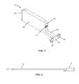
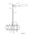
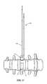
- FIG. 6is a side view of the support column of FIG. 1 , coupled to a support column inserter;
- FIG. 7is an illustration depicting a vertebral compression fracture that may be treated with the implant assembly of FIG. 1 ;
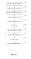
- FIG. 8is a flow chart outlining the steps according to one example method for preparing a target vertebral body for receiving the implant assembly of FIG. 1 ;
- FIG. 9is a perspective view of a cutter template used during the preparation of a fractured vertebral body to receive the implant assembly of FIG. 1 ;
- FIG. 10is a cut-away proximal view of the cutter template of FIG. 9 ;
- FIG. 11is an anterior view of a spine with the cutter template secured to a lateral aspect of the a target vertebral body of the spine and a guide wire secured to the target vertebral body through the cutter template;
- FIG. 12is a side view of a notched guide wire, according to one example embodiment
- FIG. 13is a anterior of the spine of FIG. 11 with the cutter template removed and a depth gauge deployed over the guide wire;
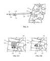
- FIG. 14is a perspective view of a horizontal cutter; according to one example embodiment.
- FIG. 15is an antero-lateral view of the spine of FIG. 13 with the depth gauge removed and a horizontal cutter deployed over the guide wire;
- FIG. 16is a lateral view of a spine with a horizontal cut formed by the cutter of FIG. 14 in the target vertebral body;
- FIG. 17is a side view of a vertical cutter according to one example embodiment
- FIG. 18is a lateral view of a spine with a vertical cut formed by the cutter of FIG. 17 connecting with the horizontal cut of FIG. 16 to make a T-cut cavity in the target vertebral body, according to one example embodiment;
- FIG. 19is a flowchart outlining the steps according to one example method for implanting the implant assembly of FIG. 1 in order to reduce a vertebral compression fracture;
- FIG. 20is a perspective view of the base assembly of FIG. 3 with a pair of rod extensions coupled to base assembly;
- FIG. 21is a perspective view of the base assembly of FIG. 20 with an elevator retainer inserted over one of the rod extensions;
- FIG. 22is an anterior view of a spine showing the base assembly with attached rod extensions and elevator retainer positioned in a target vertebral body;
- FIG. 23Ais a perspective view of a blocker, according to a first example embodiment
- FIG. 23 Bis a perspective view of a blocker, according to a second example embodiment
- FIG. 24is an antero-lateral view of the spine of FIG. 22 with a blocker advanced over one of the rod extensions and contacting the exterior of the vertebral body;
- FIG. 25Ais a lateral view of the blocker of FIG. 23A positioned adjacent to the target vertebral body;
- FIG. 25Bis a lateral view of the blocker of FIG. 23B positioned adjacent to the target vertebral body;
- FIG. 26is an anterior view of the spine and blocker of FIG. 25A ;
- FIG. 27is a perspective view of a shim for elevating the elevator plate above the base assembly, according to one example embodiment
- FIG. 28is a side view of a the shim of FIG. 27 inserted into the base assembly
- FIG. 29is an anterior view of a spine with a shim inserted into the base assembly implanted in the vertebral body;
- FIG. 30Ais a perspective view of the base assembly of FIG. 3 with the elevator plate in a partially elevated position;
- FIG. 30Bis a proximal view of the base assembly of FIG. 3 with the elevator plate in a partially elevated position;
- FIG. 31Ais a perspective view of the base assembly of FIG. 3 with the elevator plate in a fully elevated position;
- FIG. 31Bis a proximal view of the base assembly of FIG. 3 with the elevator plate in a fully elevated position;
- FIG. 32is an anterior view of the spine of FIG. 26 with the blocking plate being removed after the elevator plate has reached the appropriate elevated position;
- FIG. 33is an anterior view of the spine of FIG. 26 blocker removed and the support column being inserted into the base assembly;
- FIG. 34is a perspective view of the implant assembly of FIG. 1 with the elevator plate fully raised and the support column being inserted;
- FIG. 35is a perspective view of the implant assembly of FIG. 1 with the support column fully inserted;
- FIG. 36is a perspective antero-lateral view of a spine with the implant assembly of FIG. 1 fully deployed in the target vertebral body and with a locking screw being engaged to lock the support column to the base assembly;
- FIG. 37is a perspective view of the implant assembly of FIG. 1 , with the support column fully inserted and affixed to the base assembly with a locking screw;
- FIG. 38is an anterior view of a spine with the implant assembly of FIG. 1 implanted in the target vertebral body;
- FIG. 39is a lateral view of a spine with the implant assembly of FIG. 1 implanted in the target vertebral body.
- FIGS. 1-2illustrate one example embodiment of a fracture reduction implant 10 for treating a vertebral fracture.
- the implant 10is inserted into a cavity formed in the fractured (target) vertebral body where it is expanded to restore the height of the vertebra and prevent recollapse in the future.
- the implantis optimized for insertion from a lateral access approach to the spine.
- the implant 10may be used in any of the cervical, thoracic, and lumbar spine and may be sized accordingly.
- the implant 10includes a base assembly 12 and a support column 14 .
- a lock, for example, the locking screw 16may also be provided to lock the support column 14 to the base assembly 12 .
- the base assembly 12includes a base plate 18 , a support strut 20 extending generally perpendicularly from the base plate 18 , and an elevator plate 22 .
- the base plate 18has (by way of example) a generally rectangular footprint dimensioned to allow positioning across the vertebral body from a lateral insertion approach.
- the length of the base plate 18extends from a distal or leading end 24 to a proximal or trailing end 26 .
- the length of the base plate 18is preferably such that the base plate 18 spans the length of the vertebral body when inserted such that the proximal end 24 and distal end 26 extends to the cortical outer wall of the vertebral body, providing a solid base for the implant 10 .
- the base plate 18 lengthmay be in the range of 45 mm to 60 mm.
- the base platemay have a width in the range of 14 mm to 26 mm.
- the height of the base assembly 12including the base plate 20 and the support strut 20 , may be in the range of 12 mm to 22 mm.
- multiple base assemblies according to different size configurationsare provided in order to match the implant 10 to the particular patient anatomy.
- base assembliesmay be provided with length dimensions increasing in 5 mm increments from 45 mm to 60 mm, width dimensions of 14 mm and 18 mm, and height dimensions increasing in 2 mm increments from 12 mm to 22 mm.
- the support strut 20extends from the base plate 18 and includes a includes an upper surface 30 , a first side wall 32 , and second side wall 34 , such that a slot 36 is formed which extends from the base plate 18 .
- the slot 36is dimensioned to receive the support column 14 therethrough.
- Viewing windows 35 in the form of vertical slotsare situated in the center of each of the first side wall 32 and second side wall 34 .
- the viewing windows 35are recognizable in an A/P (Anterior/Posterior) fluoroscopy image to aid with implant positioning during insertion.
- a longitudinal channel 37extends along the upper surface of the base plate 18 .
- the longitudinal channel 37is aligned with the slot 36 in the support strut 20 and extends from and opening in the proximal end 26 to a position short of the distal end 24 but beyond the support strut 20 .
- the longitudinal channel 37has a width dimension to accommodate the support column 14 which slides into position through the longitudinal channel 37 and slot 36 .
- the upper surface of the base plate 18also includes a recess 39 in which the elevator plate 22 rests such that it is flush with the base plate 18 when in the fully lowered, insertion position.
- the elevator plate 22has (by way of example) a generally rectangular shape to match the rectangular shape of the base plate 18 .
- the width of the elevator plate 22is approximately equal to the width of the base plate 18 , and, as previously indicated sits flush with the exterior surfaces of the base plate 18 by virtue of the recess 39 in which the elevator plate is received.
- a pair of slits 38extend longitudinally through the interior of the elevator plate 18 .
- the first side wall 32 and the second side wall 34 of the support strut 20extend through the slits 38 such that the elevator plate 22 may move vertically along the support strut 20 from the base plate 18 to the upper surface 30 of the support strut 20 .
- FIG. 4illustrates the proximal end 26 of base plate 18 which includes two receptacles 28 .
- the receptacles 28are configured for removable coupling with instruments used to facilitate insertion of the implant 10 , including for example, a guide rod 50 and blocker rod 140 ( FIG. 20 ).
- Receptacles 28are also each configured such that they can receive and engage a lock screw 16 .
- the lock screws 16may be used to lock the support t column 14 to the base assembly 12 .
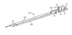
- the support column 14includes a body 40 having a distal end 41 and a proximal end 42 , a neck 44 extending proximally from the bottom of the proximal end 42 , and an elongated end face 45 situated at the end of the neck 44 .
- the body 40is inserted through the support strut 20 , supporting and maintain the elevator plate 22 in the elevated position.
- the proximal end 42 of body 40contains an insertion aperture 43 configured to threadedly couple with a support column inserter 55 , as illustrated in FIG. 6 .
- the length of the body 40matches approximately the length of the elevator plate 22 and the length of the neck is matches approximately the length of the base plate 18 from the proximal end 26 to the start of the elevator plate 18 such that when the support column 14 is fully inserted, the end face 45 rests flush against the proximal end 26 of the base plate.
- a pair of guide holes 46 in the end face 45align with the receptacles 28 of the base plate distal end 26 ( FIG. 35 ).
- the guide holes 46are dimensioned such that they are capable of slidably passing over various instruments, including, but not limited to the guide rod 50 and the blocking rod 140 as shown in FIG. 19 .
- These guide holes 46are also dimensioned to permit passage of the shaft of locking screw 16 but not the head of the locking screw 16 , such that the locking screw may engage one of the base plate receptacles through a guide hole to lock the support column 14 to the base assembly 12 ( FIG. 36 ).
- FIG. 7is an illustration of a fractured vertebra 52 in the human patients spine for which the implant 10 may be deployed for treatment.
- FIG. 8sets forth steps, which are depicted in FIGS. 9 - 18 , utilized according to one example method for preparing a target vertebra 52 within the spine to receive the implant 10 .
- a lateral approache.g. a neurophysiology-guided transpsoas approach.
- a cutter template 64corresponding to the desired width and height of the implant 10 is chosen.
- the cutter template 64has a head 65 that matches the shape of the T-cut which is to be created in the vertebral body.
- the headincludes at least one, and preferably 3, small securing spikes 66 extending distally from the head.
- the head 65also includes a viewing slot 69 formed therethrough to help ensure proper orientation with A/P fluoroscopy.
- a cannulated shaft 67extends proximally from the head 65 and connects with an aperture 68 extending through the head 65 . Together, the cannulated shaft 67 and aperture 68 are configured to permit passage of a guide wire.
- A/P and lateral fluoroscopy viewsmay be utilized to place the template 64 in the desired position and orientation on the target fractured vertebral body 52 .
- the template 64is secured to the vertebral body 52 by impacting the shaft 67 to penetrate the securing spikes 66 into the vertebral body 52 .
- a guide wire 70may be advanced into the vertebral body through the cannulated shaft 67 ( FIG. 11 ).
- the cannulated shaftguides the guide wire into the correct position and supports the guide wire to prevent excessive bending as the wire is driven into the vertebral body 52 .
- the tip 72 of the guide wire 70may be a trocar tip or a blunt tip.
- the guide wire 70directs the cutter instruments and is also used to determine the width of the vertebral body 52 , and hence the length of the implant 10 to be implanted.
- the guide wire 70may include notched depth markings 74 such that the depth of the guide wire 70 may be read directly off of the guide wire 70 .
- the notchesmay be formed at 45 mm, 50 mm, 55 mm, and 60 mm (corresponding to the implant lengths provided according to a preferred example) from the tip of the guide wire 70 .
- a depth gauge 75may be used to determine the width of the vertebral body 52 (and length of the implant 10 to be implanted). As illustrated in FIG.
- the depth gauge 75includes a cannulated distal end 76 which can be advanced over the guide wire 70 until it rests on the vertebral body 52 .
- the guide wire 70extends out of the cannulated distal end 76 along a handle having depth markings 77 that correspond to the length of wire extending distally beyond the distal end 76 of the depth gauge (i.e. the length of wire penetrated into the vertebral body).
- a first, horizontal cut 98is made in the fractured vertebral body 52 using a horizontal cutter 78 .
- the horizontal cutter 78includes serrations 85 around the distal cutting end 84 for cutting through the vertebral body 52 .
- a shoulder 88 adjacent to the proximal end 80prevents advancement of the cutter 78 through the vertebral body into the contralateral tissues.
- the cuttermay be provided in multiple lengths corresponding to the length options of the implant 10 .
- a threaded member 82 at the proximal end 80permits coupling to a handle, such as the cutter holder 92 .
- the proximal end 80includes a cannulated aperture 90 extending into the interior of the cutter body such that the horizontal cutter 78 may be introduced over the guide wire 70 .
- the horizontal cutter 78includes viewing slots, including distal viewing slot 85 and proximal viewing slot 86 that are visible under A/P fluoroscopy.
- the viewing slots 86 and 87are spaced to correspond to implant length.
- the distal slot 86indicates how far the cutter needs to be advanced to reach the contralateral margin of the vertebral body 52 .
- the cutter holder 92may be further coupled to a handle outfitted with a strike plate (for example, the cannulated T-handle 94 of FIG. 15 ).
- a forked mallet 96(or similar instrument suited for striking the T-handle 94 around the guide wire 70 ) may be used to drive the horizontal cutter 78 into the fractured vertebral body 52 .
- the horizontal cutter 98should be advanced until a horizontal cut 98 has been made through the contralateral cortical margin 100 , as indicated by the distal viewing slot 86 .
- the guide wire 70may be removed and the horizontal cut 98 and vertical cut 116 can be finished without the guide wire 70 , preventing inadvertent advancement of the guide wire 70 into the contralateral tissues.
- the horizontal cutter 78along with the cutter holder 92 and cannulated T-handle 94 , may be removed ( FIG. 16 ).
- a second, vertical cut 116is made through the fractured vertebral body 52 using a vertical cutter 102 .
- the horizontal cut 98acts as a guide for the vertical cutter 102 , illustrated in FIG. 17 .
- the vertical cutter 102includes a sled 108 , dimensioned to be received into the horizontal cut 98 , with a tapered distal end 109 for easy insertion through the horizontal cut 98 as the vertical cutter 102 is advanced into the fractured vertebral body 52 .
- the sledalso includes a distal viewing slot 110 that is visible under A/P fluoroscopy.
- the vertical cutter 116also includes serrated edges 112 perpendicular to the distal end 108 , a shoulder 114 adjacent to the proximal end 104 for preventing inadvertent advancement into the contralateral tissues, and a threaded member 106 at the proximal or trailing end 104 for threadably receiving the cutter holder 92 .
- the vertical cutter 102is assembled to the cutter holder 92 via the threaded member 106 at the proximal end 104 of the vertical cutter 102 .
- the cutter holder 92may be further coupled to a handle outfitted with a strike plate (for example, the cannulated T-handle 94 of FIG. 15 ) which can be impacted to drive the cutter.
- the vertical cutter 102may then be advanced through the vertebral body 52 until it has aligned with the contralateral cortical margin 100 of the vertebral body 52 , as indicated by the distal viewing slot 110 .
- FIG. 18depicts the vertebral body 52 with T-cut 117 formed there in.
- FIG. 19sets forth steps, which are depicted in FIGS. 19-36 , utilized according to one example method for deploying the implant into the target vertebral body 52 .
- the guide rod 50is inserted into one receptacle 28 on the base plate 18 .
- the guide rod 50will be used to insert the implant into the T-cut 117 and later, as a guide for inserting distraction shims.
- the guide rod 50includes a quick connect proximal end (e.g. male Hudson connector) which can be attached to a handle to aid in threading the guide rod 50 into the receptacle 28 .
- the blocker rod 150is inserted into the second receptacle 28 on the base plate 18 .
- the blocker rod 140will be used to guide positioning of a blocker 146 which prevents the implant 10 from advancing distally during shim insertion to elevate the elevation plate 22 .
- the blocker rod 140may also have a quick connect proximal end which can be attached to a handle to aid in threaded coupling to the receptacle 28 .
- the blocker rod 140may be shorter than the guide rod 50 and/or may be of different color than the guide rod 50 .
- An elevator plate retainer 142( FIG. 21 ) may be employed to prevent the elevator plate 22 from lifting off the base plate 18 during implantation of the base assembly 12 .
- the elevator plate retainer 142includes a cannulated shaft 143 , dimensioned to pass over the guide rod 50 , and a head 144 including an elongate extension that sits above base plate 18 and elevator plate 22 to prevent the elevator plate 22 from moving.
- the elevator plate retaineris introduced over the guide rod 50 until the elongate extension of the head 1844 passes into the slot 36 in the support strut 20 .
- the implant base assembly 12is inserted into the T-cut cavity 117 (step 124 ), as shown in FIG. 22 .
- FIGS. 23A and 23Billustrate a pair of example embodiments of blocker 146 .
- the blocker 146includes a blocker plate 148 situated at the distal end of a cannulated shaft 147 .
- the blocker plate 148includes a cutout region 149 that facilitates slidable insertion of distraction shims and the support column 14 past the blocker plate 148 and into the base plate assembly 12 .
- a set screw 152encroaches into the cannulation 150 of the shaft 147 to secure the blocker 146 to the blocker rod 140 , which in turn is secured to the base plate 18 (thus preventing the base assembly 12 from further advancement).
- the blocker shown in FIG. 23Ahas a metallic (e.g.
- the blocker shown in FIG. 23Bincludes a polymer (e.g. PEEK) blocker plate with a small (and radiolucent) foot print maximum visualization.
- the blocker 146is introduced over the blocker rod 140 until the blocker plate 148 contacts the vertebral body 52 .
- the blocker 146is then secured to the blocker rod 140 with the set screw 152 .
- a plurality of shims 156are successively inserted to raise the elevator plate 22 to the selected height.
- the distraction shims 156have a tapered distal end 158 that facilitates lifting of the elevator plate 22 as the shim is inserted down the longitudinal channel 37 and through the slot 36 in the support strut 20 .
- a guide tube 162 along the side of the shim 156is dimensioned to permit passage of the guide rod 52 such that the shim is easily guided into and along the channel 37 and slot 36 .
- a shaft 160extends proximally from the shim 156 to facilitate insertion of the shim.
- the end of the shaft 160includes a knob 168 that facilitates removal of the shim (for example using the forked mallet 96 .
- a viewing slot 166 situated near the distal end of the shimis viewable under A/P fluoroscopy to monitor shim advancement.
- the elevator plate 22is lifted upward such that the cancellous bone above it is compressed toward the cortical endplate.
- the shim 156is advanced until the view slot 166 is viewable past the distal end of the support strut 20 .
- the small shim 156may then be removed and a second larger shim 156 may be inserted such that the elevator plate 22 is lifted further upward compressing the cancellous bone and lifting the cortical endplate.
- FIGS. 30A-Bdepict the base plate 18 and elevator plate 22 after partial elevation of the elevator plate 22 . Insertion of sequentially larger shims 156 continues until the elevator plate is fully raised to the selected height. With the elevator plate 22 raised to the final position, the blocker plate 146 and blocker rod 140 are removed (step 132 ) in preparation for insertion of the support column.
- the support column 14is inserted into the base plate assembly 14 as shown in FIGS. 33-35 .
- the support column 14is coupled to the support column inserter 54 which is threaded into the hole 43 in the body 40 of the support column.
- the support column inserter 54may have a quick connect proximal end which can be attached to a handle to aid in threaded coupling to the hole 43 .
- a guide hole 46 of the support column end face 45is advanced over the guide rod 52 in order to guide the support column into position.
- the support column 14is advanced through the longitudinal channel 37 and slot 36 until the end face 45 rests flush against the distal end 28 of the base plate 20 .
- a locking screw 16is then passed through the second guide hole 46 with a screw driver 170 (having a length greater than the guide rod 52 and support column insertion rod 54 such that it is not interfered with) and secured into the open receptacle 28 of base plate to secure the support column (step 136 ).
- the guide rod 52 and support column inserter 54are then removed, and if desired, a second locking screw 16 may be secured into the open receptacle 28 through the now open guide hole 46 .
- FIGS. 38-39show the final implantation configuration of the implant 10 in the reduced vertebra 172 . Materials such as bone growth promoting materials or cement may be packed into the void created by the elevation of the elevation plate 22 .
Landscapes
- Health & Medical Sciences (AREA)
- Orthopedic Medicine & Surgery (AREA)
- Engineering & Computer Science (AREA)
- Biomedical Technology (AREA)
- Life Sciences & Earth Sciences (AREA)
- Animal Behavior & Ethology (AREA)
- Veterinary Medicine (AREA)
- Oral & Maxillofacial Surgery (AREA)
- Public Health (AREA)
- Heart & Thoracic Surgery (AREA)
- General Health & Medical Sciences (AREA)
- Surgery (AREA)
- Transplantation (AREA)
- Neurology (AREA)
- Cardiology (AREA)
- Vascular Medicine (AREA)
- Molecular Biology (AREA)
- Medical Informatics (AREA)
- Nuclear Medicine, Radiotherapy & Molecular Imaging (AREA)
- Dentistry (AREA)
- Physical Education & Sports Medicine (AREA)
- Prostheses (AREA)
- Surgical Instruments (AREA)
Abstract
Description
Claims (15)
Priority Applications (1)
| Application Number | Priority Date | Filing Date | Title |
|---|---|---|---|
| US13/184,574US8795369B1 (en) | 2010-07-16 | 2011-07-18 | Fracture reduction device and methods |
Applications Claiming Priority (3)
| Application Number | Priority Date | Filing Date | Title |
|---|---|---|---|
| US36512210P | 2010-07-16 | 2010-07-16 | |
| US36510810P | 2010-07-16 | 2010-07-16 | |
| US13/184,574US8795369B1 (en) | 2010-07-16 | 2011-07-18 | Fracture reduction device and methods |
Publications (1)
| Publication Number | Publication Date |
|---|---|
| US8795369B1true US8795369B1 (en) | 2014-08-05 |
Family
ID=51228985
Family Applications (2)
| Application Number | Title | Priority Date | Filing Date |
|---|---|---|---|
| US13/184,576ActiveUS9144501B1 (en) | 2010-07-16 | 2011-07-18 | Fracture reduction device and methods |
| US13/184,574Active2031-10-18US8795369B1 (en) | 2010-07-16 | 2011-07-18 | Fracture reduction device and methods |
Family Applications Before (1)
| Application Number | Title | Priority Date | Filing Date |
|---|---|---|---|
| US13/184,576ActiveUS9144501B1 (en) | 2010-07-16 | 2011-07-18 | Fracture reduction device and methods |
Country Status (1)
| Country | Link |
|---|---|
| US (2) | US9144501B1 (en) |
Cited By (3)
| Publication number | Priority date | Publication date | Assignee | Title |
|---|---|---|---|---|
| US20140088710A1 (en)* | 2010-07-12 | 2014-03-27 | Alphatec Spine, Inc. | Interbody fusion implant and related methods |
| US20150081025A1 (en)* | 2013-03-12 | 2015-03-19 | Spine Wave, Inc. | Apparatus for use in spinal interbody fusion |
| US11129728B1 (en)* | 2018-10-03 | 2021-09-28 | Guillermo Molina | Surgically implantable joint spacer |
Citations (111)
| Publication number | Priority date | Publication date | Assignee | Title |
|---|---|---|---|---|
| US4969888A (en) | 1989-02-09 | 1990-11-13 | Arie Scholten | Surgical protocol for fixation of osteoporotic bone using inflatable device |
| US5827289A (en) | 1994-01-26 | 1998-10-27 | Reiley; Mark A. | Inflatable device for use in surgical protocols relating to treatment of fractured or diseased bones |
| US6213672B1 (en) | 1997-10-21 | 2001-04-10 | George J. Varga | Telescoping pole & cleaning tool |
| US6241734B1 (en) | 1998-08-14 | 2001-06-05 | Kyphon, Inc. | Systems and methods for placing materials into bone |
| US6248110B1 (en) | 1994-01-26 | 2001-06-19 | Kyphon, Inc. | Systems and methods for treating fractured or diseased bone using expandable bodies |
| US6280456B1 (en) | 1997-08-15 | 2001-08-28 | Kyphon Inc | Methods for treating bone |
| US20030050644A1 (en) | 2001-09-11 | 2003-03-13 | Boucher Ryan P. | Systems and methods for accessing and treating diseased or fractured bone employing a guide wire |
| US6562074B2 (en) | 2001-10-17 | 2003-05-13 | Medicinelodge, Inc. | Adjustable bone fusion implant and method |
| US20030130664A1 (en) | 1998-08-14 | 2003-07-10 | Kyphon Inc. | Systems and methods for treating vertebral bodies |
| US20030171812A1 (en) | 2001-12-31 | 2003-09-11 | Ilan Grunberg | Minimally invasive modular support implant device and method |
| US20040087947A1 (en) | 2002-08-28 | 2004-05-06 | Roy Lim | Minimally invasive expanding spacer and method |
| US6740093B2 (en) | 2000-02-28 | 2004-05-25 | Stephen Hochschuler | Method and apparatus for treating a vertebral body |
| AU2002323730B2 (en) | 1997-06-09 | 2004-09-30 | Kyphon Inc. | Systems for treating fractured or diseased bone using expandable bodies |
| CN2730336Y (en) | 2004-09-20 | 2005-10-05 | 李孔嘉 | Spinal reconstructive reducer implanted in the vertebral body via the vertebral stem |
| US20050278036A1 (en) | 2004-06-09 | 2005-12-15 | Ceravic | Method for restoration of human or animal bone anatomy, and expansible prosthetic implant allowing implementation of this method |
| US20050288678A1 (en) | 1994-01-26 | 2005-12-29 | Kyphon Inc. | Vertebral body having an altered native cancellous bone volume and related treatment methods |
| US6981981B2 (en) | 1994-01-26 | 2006-01-03 | Kyphon Inc. | Inflatable device for use in surgical protocol relating to fixation of bone |
| US20060095138A1 (en) | 2004-06-09 | 2006-05-04 | Csaba Truckai | Composites and methods for treating bone |
| US7044954B2 (en) | 1994-01-26 | 2006-05-16 | Kyphon Inc. | Method for treating a vertebral body |
| US20060122701A1 (en) | 2004-11-23 | 2006-06-08 | Kiester P D | Posterior lumbar interbody fusion expandable cage with lordosis and method of deploying the same |
| US20060129244A1 (en) | 2004-10-25 | 2006-06-15 | Alphaspine, Inc. | Expandable intervertebral spacer method and apparatus |
| US20060155296A1 (en) | 2005-01-07 | 2006-07-13 | Celonova Biosciences, Inc. | Three-dimensional implantable bone support |
| US7114501B2 (en) | 2000-08-14 | 2006-10-03 | Spine Wave, Inc. | Transverse cavity device and method |
| US20060264967A1 (en) | 2003-03-14 | 2006-11-23 | Ferreyro Roque H | Hydraulic device for the injection of bone cement in percutaneous vertebroplasty |
| US7153306B2 (en) | 2000-10-25 | 2006-12-26 | Kyphon Inc. | Systems and methods for reducing fractured bone using a fracture reduction cannula |
| WO2007002108A2 (en) | 2005-06-20 | 2007-01-04 | Synthes (U.S.A.) | Apparatus and methods for treating bone |
| US7166121B2 (en) | 1994-01-26 | 2007-01-23 | Kyphon Inc. | Systems and methods using expandable bodies to push apart cortical bone surfaces |
| US20070032791A1 (en) | 2005-07-14 | 2007-02-08 | Greenhalgh E S | Expandable support device and method of use |
| US20070050030A1 (en) | 2005-08-23 | 2007-03-01 | Kim Richard C | Expandable implant device with interchangeable spacer |
| US20070055259A1 (en) | 2005-08-17 | 2007-03-08 | Norton Britt K | Apparatus and methods for removal of intervertebral disc tissues |
| US20070067034A1 (en) | 2005-08-31 | 2007-03-22 | Chirico Paul E | Implantable devices and methods for treating micro-architecture deterioration of bone tissue |
| US20070093822A1 (en) | 2005-09-28 | 2007-04-26 | Christof Dutoit | Apparatus and methods for vertebral augmentation using linked expandable bodies |
| US7226481B2 (en) | 2000-07-21 | 2007-06-05 | Spineology, Inc. | Expandable porous mesh bag device and methods of use for reduction, filling, fixation, and supporting of bone |
| US7241303B2 (en) | 1994-01-26 | 2007-07-10 | Kyphon Inc. | Devices and methods using an expandable body with internal restraint for compressing cancellous bone |
| US20070162132A1 (en) | 2005-12-23 | 2007-07-12 | Dominique Messerli | Flexible elongated chain implant and method of supporting body tissue with same |
| US20070179611A1 (en) | 2005-12-22 | 2007-08-02 | Dipoto Gene P | Methods and devices for replacement of intervertebral discs |
| US20070255410A1 (en)* | 2006-04-27 | 2007-11-01 | Sdgi Holdings, Inc. | Centrally driven expandable implant and method |
| US20080004705A1 (en) | 2006-06-14 | 2008-01-03 | Dominique Rogeau | Vertebral replacement device |
| US20080009877A1 (en) | 2006-07-07 | 2008-01-10 | Meera Sankaran | Medical device with expansion mechanism |
| US20080045966A1 (en)* | 2002-01-14 | 2008-02-21 | Dynamic Spine, Inc. | Apparatus and method for performing spinal surgery |
| US20080058674A1 (en) | 2006-08-29 | 2008-03-06 | Lex Jansen | Tissue extraction device and method of using the same |
| US20080065190A1 (en) | 1994-01-26 | 2008-03-13 | Kyphon Inc. | Methods for treating a fractured and/or diseased and/or weakened bone |
| US20080086133A1 (en) | 2003-05-16 | 2008-04-10 | Spineology | Expandable porous mesh bag device and methods of use for reduction, filling, fixation and supporting of bone |
| WO2008060277A2 (en) | 2006-11-15 | 2008-05-22 | Aoi Medical, Inc. | Tissue cavitation device and method |
| US20080177387A1 (en) | 2006-11-01 | 2008-07-24 | Warsaw Orthopedic, Inc. | Implants and Related Devices for Monitoring Bony Fusion |
| WO2008097659A2 (en) | 2007-02-08 | 2008-08-14 | Krueger John A | Device, system and method for delivering a curable material into bone |
| US20080234687A1 (en) | 2005-08-16 | 2008-09-25 | Laurent Schaller | Devices for treating the spine |
| US20080249604A1 (en) | 2007-03-30 | 2008-10-09 | Brian Donovan | Apparatus and method for medical procedures within a spine |
| US20080281364A1 (en) | 2007-05-08 | 2008-11-13 | Spineworks Medical, Inc. | Systems, devices and methods for stabilizing bone |
| US20080294167A1 (en) | 2007-05-21 | 2008-11-27 | Brian Schumacher | Articulating cavitation device |
| US20080300598A1 (en)* | 2007-05-31 | 2008-12-04 | Spine Wave, Inc. | Expandable Interbody Fusion Device |
| US20090024217A1 (en) | 2007-07-17 | 2009-01-22 | Levy Mark M | Expandable bone device |
| US20090054934A1 (en) | 2007-07-25 | 2009-02-26 | Depuy Spine, Inc. | Expandable fillers for bone cement |
| US7500992B2 (en) | 2004-10-05 | 2009-03-10 | Kung-Chia Li | Distractable body augmenter capable of being planted through a pedicle for vertebral body reconstruction |
| US20090076520A1 (en) | 2007-09-14 | 2009-03-19 | Gil-Woon Choi | Apparatus For Treating Bone |
| US20090088788A1 (en) | 2007-09-28 | 2009-04-02 | Steven Mouw | Methods and apparatus having multiple separately actuatable expandable members |
| US20090138043A1 (en) | 2007-11-28 | 2009-05-28 | Medtronic Spine Llc | Threaded access cannula and methods of using the same |
| US20090138086A1 (en)* | 2007-11-27 | 2009-05-28 | Warsaw Orthopedic, Inc. | Stackable Intervertebral Devices and Methods of Use |
| US20090164016A1 (en) | 2007-12-19 | 2009-06-25 | Bassem Georgy | Device and method for orthopedic fracture fixation |
| US20090204215A1 (en)* | 2008-02-07 | 2009-08-13 | K2M, Inc. | Expandable vertebral device with cam lock |
| US20090240334A1 (en) | 2008-03-19 | 2009-09-24 | Richelsoph Marc E | Vertebral device for restoration of vertebral body height |
| US20090247664A1 (en) | 2008-02-01 | 2009-10-01 | Dfine, Inc. | Bone treatment systems and methods |
| US20090276048A1 (en) | 2007-05-08 | 2009-11-05 | Chirico Paul E | Devices and method for bilateral support of a compression-fractured vertebral body |
| US7615052B2 (en) | 2005-04-29 | 2009-11-10 | Warsaw Orthopedic, Inc. | Surgical instrument and method |
| US20090281627A1 (en) | 2005-06-02 | 2009-11-12 | Spinevision | Filling material for filling a vertebral body cavity, intervertebral prosthetic disc nucleus and vertebroplasty prosthesis comprising such a material |
| US7621952B2 (en) | 2004-06-07 | 2009-11-24 | Dfine, Inc. | Implants and methods for treating bone |
| US7623902B2 (en) | 2005-03-07 | 2009-11-24 | Leucadia 6, Llc | System and methods for improved access to vertebral bodies for kyphoplasty, vertebroplasty, vertebral body biopsy or screw placement |
| US20090299401A1 (en) | 2008-06-02 | 2009-12-03 | Loma Vista Medical, Inc. | Inflatable medical devices |
| US20090299282A1 (en) | 2007-11-16 | 2009-12-03 | Osseon Therapeutics, Inc. | Steerable vertebroplasty system with a plurality of cavity creation elements |
| US20090299373A1 (en) | 2008-05-30 | 2009-12-03 | Cook Incorporated | Kyphoplasty banded balloon catheter |
| US20090326538A1 (en) | 2006-12-15 | 2009-12-31 | Sennett Andrew R | Devices and methods for fracture reduction |
| DE102008030690A1 (en) | 2008-07-01 | 2010-01-07 | Hörmansdörfer, Gerd | Expander for producing bony cavity for treating e.g. osteoporotic fracture, has flexibly deformable expansion element comprising leaf spring formed from outer and inner leaves, where outer leaf is positively supported on inner leaf |
| US20100023017A1 (en) | 2006-04-20 | 2010-01-28 | Depuy Spine, Inc. | Instrumentation kit for delivering viscous bone filler material |
| US20100030284A1 (en) | 2005-12-23 | 2010-02-04 | Zimmer Gmbh | Coated textiles |
| US20100030216A1 (en) | 2008-07-30 | 2010-02-04 | Arcenio Gregory B | Discectomy tool having counter-rotating nucleus disruptors |
| US20100036381A1 (en) | 2008-08-07 | 2010-02-11 | Ryan Vanleeuwen | Cavity creator with integral cement delivery lumen |
| US7666227B2 (en) | 2005-08-16 | 2010-02-23 | Benvenue Medical, Inc. | Devices for limiting the movement of material introduced between layers of spinal tissue |
| US20100054075A1 (en) | 2008-09-02 | 2010-03-04 | Cook Incorporated | Vertebroplasty all in one mixer |
| US20100070049A1 (en) | 2008-05-06 | 2010-03-18 | O'donnell Patrick | Method and apparatus for treating compression fractures in vertebral bodies |
| US7682378B2 (en) | 2004-11-10 | 2010-03-23 | Dfine, Inc. | Bone treatment systems and methods for introducing an abrading structure to abrade bone |
| US20100082073A1 (en) | 2008-09-23 | 2010-04-01 | Lanx, Inc. | Methods and Compositions for Stabilization of a Vertebra |
| US20100082033A1 (en) | 2008-09-30 | 2010-04-01 | Dfine, Inc. | System for use in treatment of vertebral fractures |
| US20100087826A1 (en) | 2003-05-16 | 2010-04-08 | Spinewave, Inc. | Tissue Distraction Device |
| US20100100184A1 (en) | 2008-06-24 | 2010-04-22 | John Krueger | Method and structure for stabilizing a vertebral body |
| US7708733B2 (en) | 2003-10-20 | 2010-05-04 | Arthrocare Corporation | Electrosurgical method and apparatus for removing tissue within a bone body |
| US7713273B2 (en) | 2005-11-18 | 2010-05-11 | Carefusion 2200, Inc. | Device, system and method for delivering a curable material into bone |
| WO2010063111A1 (en) | 2008-12-03 | 2010-06-10 | The Royal Institution For The Advancement Of Learning/Mcgill University | Device and method for percutaneous intravertebral osteotomy |
| US7744637B2 (en) | 2001-03-08 | 2010-06-29 | Spine Wave, Inc. | Method for restoring vertebral body height |
| US20100179656A1 (en) | 2008-03-28 | 2010-07-15 | Charles Theofilos | Expandable cage with locking device |
| US7758644B2 (en) | 2002-11-21 | 2010-07-20 | Warsaw Orthopedic, Inc. | Systems and techniques for intravertebral spinal stabilization with expandable devices |
| US20100198225A1 (en) | 2007-04-17 | 2010-08-05 | Thompson Andrew Nmi | Shape memory spine jack |
| US20100217335A1 (en) | 2008-12-31 | 2010-08-26 | Chirico Paul E | Self-expanding bone stabilization devices |
| US7789912B2 (en) | 2004-01-08 | 2010-09-07 | Spine Wave, Inc. | Apparatus and method for injecting fluent material at a distracted tissue site |
| WO2010100287A1 (en) | 2009-03-06 | 2010-09-10 | Somatex Medical Technologies Gmbh | Barrier for implantation into bone, in particular for vertebroplasty |
| US20100234866A1 (en) | 2009-03-13 | 2010-09-16 | Greg Arcenio | Battery operated nucleus disruptor device for intervertebral disc |
| DE102009011566A1 (en) | 2009-03-06 | 2010-09-16 | Somatex Medical Technologies Gmbh | Barrier for implantation into bone in vertebroplasty use in injection apparatus, has closure apparatus placed on or in filling hole to automatically close or clog hole after completion of filling of bag |
| DE102009011561A1 (en) | 2009-03-06 | 2010-09-16 | Somatex Medical Technologies Gmbh | Barrier for implantation into bone in vertebroplasty use in injection apparatus, has closure apparatus placed on or in filling hole to automatically close or clog hole after completion of filling of bag |
| US7803188B2 (en) | 2002-08-27 | 2010-09-28 | Warsaw Orthopedic, Inc. | Systems and methods for intravertebral reduction |
| US20100247478A1 (en) | 2009-02-18 | 2010-09-30 | Clineff Theodore D | Method for stabilizing vertebral body architecture |
| US7811291B2 (en) | 2007-11-16 | 2010-10-12 | Osseon Therapeutics, Inc. | Closed vertebroplasty bone cement injection system |
| US7875078B2 (en) | 2004-08-25 | 2011-01-25 | Spine Wave, Inc. | Expandable interbody fusion device |
| US7901409B2 (en) | 2006-01-20 | 2011-03-08 | Canaveral Villegas Living Trust | Intramedullar devices and methods to reduce and/or fix damaged bone |
| US7909873B2 (en) | 2006-12-15 | 2011-03-22 | Soteira, Inc. | Delivery apparatus and methods for vertebrostenting |
| US7955339B2 (en) | 2005-05-24 | 2011-06-07 | Kyphon Sarl | Low-compliance expandable medical device |
| US7972382B2 (en) | 2006-12-26 | 2011-07-05 | Warsaw Orthopedic, Inc. | Minimally invasive spinal distraction devices and methods |
| US7972340B2 (en) | 1997-08-13 | 2011-07-05 | Kyphon Sarl | Systems and methods for injecting flowable materials into bones |
| US7985228B2 (en) | 2006-08-25 | 2011-07-26 | Kyphon Sarl | Apparatus and methods for use of expandable members in surgical applications |
| US8048030B2 (en) | 1998-12-09 | 2011-11-01 | Cook Medical Technologies Llc | Hollow curved superelastic medical needle and method |
| US8070754B2 (en) | 2007-05-31 | 2011-12-06 | Fabian Henry F | Spine surgery method and instrumentation |
| US8109933B2 (en) | 2007-04-03 | 2012-02-07 | Dfine, Inc. | Bone treatment systems and methods |
| US8114084B2 (en) | 2007-03-07 | 2012-02-14 | Vertech, Inc. | Expandable blade device for stabilizing compression fractures |
Family Cites Families (5)
| Publication number | Priority date | Publication date | Assignee | Title |
|---|---|---|---|---|
| NZ513472A (en) | 1997-06-09 | 2002-12-20 | Kyphon Inc | Apparatus for treating fractured or diseased bone using plastically expandable bodies |
| WO1999029246A1 (en) | 1997-12-08 | 1999-06-17 | Kyphon Inc. | Systems and methods using expandable bodies to push apart cortical bone surfaces |
| CA2333761C (en) | 1998-06-01 | 2008-05-27 | Kyphon Inc. | Expandable preformed structures for deployment in interior body regions |
| US6419705B1 (en)* | 1999-06-23 | 2002-07-16 | Sulzer Spine-Tech Inc. | Expandable fusion device and method |
| ES2395298T3 (en)* | 2006-07-14 | 2013-02-11 | Biedermann Technologies Gmbh & Co. Kg | Separator for insertion between two vertebrae |
- 2011
- 2011-07-18USUS13/184,576patent/US9144501B1/enactiveActive
- 2011-07-18USUS13/184,574patent/US8795369B1/enactiveActive
Patent Citations (129)
| Publication number | Priority date | Publication date | Assignee | Title |
|---|---|---|---|---|
| US4969888A (en) | 1989-02-09 | 1990-11-13 | Arie Scholten | Surgical protocol for fixation of osteoporotic bone using inflatable device |
| US20080051825A1 (en) | 1994-01-26 | 2008-02-28 | Kyphon, Inc. | Systems and methods for treating bone using expandable bodies |
| US7044954B2 (en) | 1994-01-26 | 2006-05-16 | Kyphon Inc. | Method for treating a vertebral body |
| US20100082036A1 (en) | 1994-01-26 | 2010-04-01 | Kyphon Sarl | Systems and methods for treating fractured or diseased bone using expandable bodies |
| US6248110B1 (en) | 1994-01-26 | 2001-06-19 | Kyphon, Inc. | Systems and methods for treating fractured or diseased bone using expandable bodies |
| US20050119662A1 (en) | 1994-01-26 | 2005-06-02 | Kyphon Inc. | Systems and methods for treating fractured or diseased bone using expandable bodies |
| US7682364B2 (en) | 1994-01-26 | 2010-03-23 | Kyphon Sarl | Method for treating a bone |
| US20080065190A1 (en) | 1994-01-26 | 2008-03-13 | Kyphon Inc. | Methods for treating a fractured and/or diseased and/or weakened bone |
| US20050288678A1 (en) | 1994-01-26 | 2005-12-29 | Kyphon Inc. | Vertebral body having an altered native cancellous bone volume and related treatment methods |
| US7241303B2 (en) | 1994-01-26 | 2007-07-10 | Kyphon Inc. | Devices and methods using an expandable body with internal restraint for compressing cancellous bone |
| US20080058855A1 (en) | 1994-01-26 | 2008-03-06 | Kyphon, Inc. | Systems and methods treating a vertebral body |
| US5827289A (en) | 1994-01-26 | 1998-10-27 | Reiley; Mark A. | Inflatable device for use in surgical protocols relating to treatment of fractured or diseased bones |
| US7166121B2 (en) | 1994-01-26 | 2007-01-23 | Kyphon Inc. | Systems and methods using expandable bodies to push apart cortical bone surfaces |
| US6981981B2 (en) | 1994-01-26 | 2006-01-03 | Kyphon Inc. | Inflatable device for use in surgical protocol relating to fixation of bone |
| US7967827B2 (en) | 1994-01-26 | 2011-06-28 | Kyphon Sarl | Methods and devices for treating fractured and/or diseased bone using an expandable structure that remains within the bone |
| AU2002323730B2 (en) | 1997-06-09 | 2004-09-30 | Kyphon Inc. | Systems for treating fractured or diseased bone using expandable bodies |
| US7959638B2 (en) | 1997-06-09 | 2011-06-14 | Kyphon Sarl | Methods and devices for treating bone after high velocity and/or trauma fracture |
| US7972340B2 (en) | 1997-08-13 | 2011-07-05 | Kyphon Sarl | Systems and methods for injecting flowable materials into bones |
| US8034071B2 (en) | 1997-08-15 | 2011-10-11 | Kyphon Sarl | Systems and methods for forming a cavity in cancellous bone |
| US6280456B1 (en) | 1997-08-15 | 2001-08-28 | Kyphon Inc | Methods for treating bone |
| US6213672B1 (en) | 1997-10-21 | 2001-04-10 | George J. Varga | Telescoping pole & cleaning tool |
| US20080058826A1 (en) | 1998-08-14 | 2008-03-06 | Kyphon, Inc | Methods and apparatus for placing materials into bone |
| US20030130664A1 (en) | 1998-08-14 | 2003-07-10 | Kyphon Inc. | Systems and methods for treating vertebral bodies |
| US6241734B1 (en) | 1998-08-14 | 2001-06-05 | Kyphon, Inc. | Systems and methods for placing materials into bone |
| US8052661B2 (en) | 1998-12-09 | 2011-11-08 | Cook Incorporated | Hollow curved superelastic medical needle and method |
| US8048030B2 (en) | 1998-12-09 | 2011-11-01 | Cook Medical Technologies Llc | Hollow curved superelastic medical needle and method |
| US6740093B2 (en) | 2000-02-28 | 2004-05-25 | Stephen Hochschuler | Method and apparatus for treating a vertebral body |
| US7226481B2 (en) | 2000-07-21 | 2007-06-05 | Spineology, Inc. | Expandable porous mesh bag device and methods of use for reduction, filling, fixation, and supporting of bone |
| US7114501B2 (en) | 2000-08-14 | 2006-10-03 | Spine Wave, Inc. | Transverse cavity device and method |
| US7153306B2 (en) | 2000-10-25 | 2006-12-26 | Kyphon Inc. | Systems and methods for reducing fractured bone using a fracture reduction cannula |
| US7744637B2 (en) | 2001-03-08 | 2010-06-29 | Spine Wave, Inc. | Method for restoring vertebral body height |
| US7749255B2 (en) | 2001-03-08 | 2010-07-06 | Spine Wave, Inc. | Method for fusing adjacent bones |
| US7780734B2 (en) | 2001-03-08 | 2010-08-24 | Spine Wave, Inc. | Tissue distraction device |
| US8123755B2 (en)* | 2001-03-08 | 2012-02-28 | Spine Wave, Inc. | Tissue distraction device |
| US20030050644A1 (en) | 2001-09-11 | 2003-03-13 | Boucher Ryan P. | Systems and methods for accessing and treating diseased or fractured bone employing a guide wire |
| US6562074B2 (en) | 2001-10-17 | 2003-05-13 | Medicinelodge, Inc. | Adjustable bone fusion implant and method |
| US6852129B2 (en)* | 2001-10-17 | 2005-02-08 | Movdice Holding, Inc. | Adjustable bone fusion implant and method |
| US6863673B2 (en) | 2001-10-17 | 2005-03-08 | Movdice Holding, Inc. | Methods for adjustable bone fusion implants |
| US20030171812A1 (en) | 2001-12-31 | 2003-09-11 | Ilan Grunberg | Minimally invasive modular support implant device and method |
| US7261720B2 (en) | 2002-01-11 | 2007-08-28 | Kyphon Inc. | Inflatable device for use in surgical protocol relating to fixation of bone |
| US20080045966A1 (en)* | 2002-01-14 | 2008-02-21 | Dynamic Spine, Inc. | Apparatus and method for performing spinal surgery |
| US7803188B2 (en) | 2002-08-27 | 2010-09-28 | Warsaw Orthopedic, Inc. | Systems and methods for intravertebral reduction |
| US20040087947A1 (en) | 2002-08-28 | 2004-05-06 | Roy Lim | Minimally invasive expanding spacer and method |
| US7758644B2 (en) | 2002-11-21 | 2010-07-20 | Warsaw Orthopedic, Inc. | Systems and techniques for intravertebral spinal stabilization with expandable devices |
| US20060264967A1 (en) | 2003-03-14 | 2006-11-23 | Ferreyro Roque H | Hydraulic device for the injection of bone cement in percutaneous vertebroplasty |
| US20100087826A1 (en) | 2003-05-16 | 2010-04-08 | Spinewave, Inc. | Tissue Distraction Device |
| US20080086133A1 (en) | 2003-05-16 | 2008-04-10 | Spineology | Expandable porous mesh bag device and methods of use for reduction, filling, fixation and supporting of bone |
| US7708733B2 (en) | 2003-10-20 | 2010-05-04 | Arthrocare Corporation | Electrosurgical method and apparatus for removing tissue within a bone body |
| US7789912B2 (en) | 2004-01-08 | 2010-09-07 | Spine Wave, Inc. | Apparatus and method for injecting fluent material at a distracted tissue site |
| US7621952B2 (en) | 2004-06-07 | 2009-11-24 | Dfine, Inc. | Implants and methods for treating bone |
| US20050278036A1 (en) | 2004-06-09 | 2005-12-15 | Ceravic | Method for restoration of human or animal bone anatomy, and expansible prosthetic implant allowing implementation of this method |
| US20060095138A1 (en) | 2004-06-09 | 2006-05-04 | Csaba Truckai | Composites and methods for treating bone |
| US7875078B2 (en) | 2004-08-25 | 2011-01-25 | Spine Wave, Inc. | Expandable interbody fusion device |
| CN2730336Y (en) | 2004-09-20 | 2005-10-05 | 李孔嘉 | Spinal reconstructive reducer implanted in the vertebral body via the vertebral stem |
| US7500992B2 (en) | 2004-10-05 | 2009-03-10 | Kung-Chia Li | Distractable body augmenter capable of being planted through a pedicle for vertebral body reconstruction |
| US20060129244A1 (en) | 2004-10-25 | 2006-06-15 | Alphaspine, Inc. | Expandable intervertebral spacer method and apparatus |
| US7682378B2 (en) | 2004-11-10 | 2010-03-23 | Dfine, Inc. | Bone treatment systems and methods for introducing an abrading structure to abrade bone |
| US20060122701A1 (en) | 2004-11-23 | 2006-06-08 | Kiester P D | Posterior lumbar interbody fusion expandable cage with lordosis and method of deploying the same |
| US20060155296A1 (en) | 2005-01-07 | 2006-07-13 | Celonova Biosciences, Inc. | Three-dimensional implantable bone support |
| US7623902B2 (en) | 2005-03-07 | 2009-11-24 | Leucadia 6, Llc | System and methods for improved access to vertebral bodies for kyphoplasty, vertebroplasty, vertebral body biopsy or screw placement |
| US7615052B2 (en) | 2005-04-29 | 2009-11-10 | Warsaw Orthopedic, Inc. | Surgical instrument and method |
| US7955339B2 (en) | 2005-05-24 | 2011-06-07 | Kyphon Sarl | Low-compliance expandable medical device |
| US20090281627A1 (en) | 2005-06-02 | 2009-11-12 | Spinevision | Filling material for filling a vertebral body cavity, intervertebral prosthetic disc nucleus and vertebroplasty prosthesis comprising such a material |
| WO2007002108A2 (en) | 2005-06-20 | 2007-01-04 | Synthes (U.S.A.) | Apparatus and methods for treating bone |
| US20070032791A1 (en) | 2005-07-14 | 2007-02-08 | Greenhalgh E S | Expandable support device and method of use |
| US20080234687A1 (en) | 2005-08-16 | 2008-09-25 | Laurent Schaller | Devices for treating the spine |
| US7666227B2 (en) | 2005-08-16 | 2010-02-23 | Benvenue Medical, Inc. | Devices for limiting the movement of material introduced between layers of spinal tissue |
| US20070055259A1 (en) | 2005-08-17 | 2007-03-08 | Norton Britt K | Apparatus and methods for removal of intervertebral disc tissues |
| US20070050030A1 (en) | 2005-08-23 | 2007-03-01 | Kim Richard C | Expandable implant device with interchangeable spacer |
| US20070067034A1 (en) | 2005-08-31 | 2007-03-22 | Chirico Paul E | Implantable devices and methods for treating micro-architecture deterioration of bone tissue |
| US20070093822A1 (en) | 2005-09-28 | 2007-04-26 | Christof Dutoit | Apparatus and methods for vertebral augmentation using linked expandable bodies |
| US7713273B2 (en) | 2005-11-18 | 2010-05-11 | Carefusion 2200, Inc. | Device, system and method for delivering a curable material into bone |
| US20100087828A1 (en) | 2005-11-18 | 2010-04-08 | Krueger John A | Device, system and method for delivering a curable material into bone |
| US20070179611A1 (en) | 2005-12-22 | 2007-08-02 | Dipoto Gene P | Methods and devices for replacement of intervertebral discs |
| US20070162132A1 (en) | 2005-12-23 | 2007-07-12 | Dominique Messerli | Flexible elongated chain implant and method of supporting body tissue with same |
| US20100030284A1 (en) | 2005-12-23 | 2010-02-04 | Zimmer Gmbh | Coated textiles |
| US7901409B2 (en) | 2006-01-20 | 2011-03-08 | Canaveral Villegas Living Trust | Intramedullar devices and methods to reduce and/or fix damaged bone |
| US20100023017A1 (en) | 2006-04-20 | 2010-01-28 | Depuy Spine, Inc. | Instrumentation kit for delivering viscous bone filler material |
| US20070255410A1 (en)* | 2006-04-27 | 2007-11-01 | Sdgi Holdings, Inc. | Centrally driven expandable implant and method |
| US20080004705A1 (en) | 2006-06-14 | 2008-01-03 | Dominique Rogeau | Vertebral replacement device |
| US20080009877A1 (en) | 2006-07-07 | 2008-01-10 | Meera Sankaran | Medical device with expansion mechanism |
| US7985228B2 (en) | 2006-08-25 | 2011-07-26 | Kyphon Sarl | Apparatus and methods for use of expandable members in surgical applications |
| US20080058674A1 (en) | 2006-08-29 | 2008-03-06 | Lex Jansen | Tissue extraction device and method of using the same |
| US20080177387A1 (en) | 2006-11-01 | 2008-07-24 | Warsaw Orthopedic, Inc. | Implants and Related Devices for Monitoring Bony Fusion |
| WO2008060277A2 (en) | 2006-11-15 | 2008-05-22 | Aoi Medical, Inc. | Tissue cavitation device and method |
| US20090326538A1 (en) | 2006-12-15 | 2009-12-31 | Sennett Andrew R | Devices and methods for fracture reduction |
| US7909873B2 (en) | 2006-12-15 | 2011-03-22 | Soteira, Inc. | Delivery apparatus and methods for vertebrostenting |
| US7972382B2 (en) | 2006-12-26 | 2011-07-05 | Warsaw Orthopedic, Inc. | Minimally invasive spinal distraction devices and methods |
| WO2008097659A2 (en) | 2007-02-08 | 2008-08-14 | Krueger John A | Device, system and method for delivering a curable material into bone |
| US8114084B2 (en) | 2007-03-07 | 2012-02-14 | Vertech, Inc. | Expandable blade device for stabilizing compression fractures |
| US20080249604A1 (en) | 2007-03-30 | 2008-10-09 | Brian Donovan | Apparatus and method for medical procedures within a spine |
| US8109933B2 (en) | 2007-04-03 | 2012-02-07 | Dfine, Inc. | Bone treatment systems and methods |
| US20100198225A1 (en) | 2007-04-17 | 2010-08-05 | Thompson Andrew Nmi | Shape memory spine jack |
| US20090276048A1 (en) | 2007-05-08 | 2009-11-05 | Chirico Paul E | Devices and method for bilateral support of a compression-fractured vertebral body |
| US20080281364A1 (en) | 2007-05-08 | 2008-11-13 | Spineworks Medical, Inc. | Systems, devices and methods for stabilizing bone |
| US20080294167A1 (en) | 2007-05-21 | 2008-11-27 | Brian Schumacher | Articulating cavitation device |
| US20080300598A1 (en)* | 2007-05-31 | 2008-12-04 | Spine Wave, Inc. | Expandable Interbody Fusion Device |
| US7967867B2 (en) | 2007-05-31 | 2011-06-28 | Spine Wave, Inc. | Expandable interbody fusion device |
| US8070754B2 (en) | 2007-05-31 | 2011-12-06 | Fabian Henry F | Spine surgery method and instrumentation |
| US20090024217A1 (en) | 2007-07-17 | 2009-01-22 | Levy Mark M | Expandable bone device |
| US20090054934A1 (en) | 2007-07-25 | 2009-02-26 | Depuy Spine, Inc. | Expandable fillers for bone cement |
| US20090076520A1 (en) | 2007-09-14 | 2009-03-19 | Gil-Woon Choi | Apparatus For Treating Bone |
| US20090088788A1 (en) | 2007-09-28 | 2009-04-02 | Steven Mouw | Methods and apparatus having multiple separately actuatable expandable members |
| US20090299282A1 (en) | 2007-11-16 | 2009-12-03 | Osseon Therapeutics, Inc. | Steerable vertebroplasty system with a plurality of cavity creation elements |
| US7811291B2 (en) | 2007-11-16 | 2010-10-12 | Osseon Therapeutics, Inc. | Closed vertebroplasty bone cement injection system |
| US20090138086A1 (en)* | 2007-11-27 | 2009-05-28 | Warsaw Orthopedic, Inc. | Stackable Intervertebral Devices and Methods of Use |
| US20090138043A1 (en) | 2007-11-28 | 2009-05-28 | Medtronic Spine Llc | Threaded access cannula and methods of using the same |
| US20090164016A1 (en) | 2007-12-19 | 2009-06-25 | Bassem Georgy | Device and method for orthopedic fracture fixation |
| US20090247664A1 (en) | 2008-02-01 | 2009-10-01 | Dfine, Inc. | Bone treatment systems and methods |
| US20090204215A1 (en)* | 2008-02-07 | 2009-08-13 | K2M, Inc. | Expandable vertebral device with cam lock |
| US20090240334A1 (en) | 2008-03-19 | 2009-09-24 | Richelsoph Marc E | Vertebral device for restoration of vertebral body height |
| US20100179656A1 (en) | 2008-03-28 | 2010-07-15 | Charles Theofilos | Expandable cage with locking device |
| US20100070049A1 (en) | 2008-05-06 | 2010-03-18 | O'donnell Patrick | Method and apparatus for treating compression fractures in vertebral bodies |
| US20090299373A1 (en) | 2008-05-30 | 2009-12-03 | Cook Incorporated | Kyphoplasty banded balloon catheter |
| US20090299401A1 (en) | 2008-06-02 | 2009-12-03 | Loma Vista Medical, Inc. | Inflatable medical devices |
| US20100100184A1 (en) | 2008-06-24 | 2010-04-22 | John Krueger | Method and structure for stabilizing a vertebral body |
| DE102008030690A1 (en) | 2008-07-01 | 2010-01-07 | Hörmansdörfer, Gerd | Expander for producing bony cavity for treating e.g. osteoporotic fracture, has flexibly deformable expansion element comprising leaf spring formed from outer and inner leaves, where outer leaf is positively supported on inner leaf |
| US20100030216A1 (en) | 2008-07-30 | 2010-02-04 | Arcenio Gregory B | Discectomy tool having counter-rotating nucleus disruptors |
| US20100036381A1 (en) | 2008-08-07 | 2010-02-11 | Ryan Vanleeuwen | Cavity creator with integral cement delivery lumen |
| US20100054075A1 (en) | 2008-09-02 | 2010-03-04 | Cook Incorporated | Vertebroplasty all in one mixer |
| US20100082073A1 (en) | 2008-09-23 | 2010-04-01 | Lanx, Inc. | Methods and Compositions for Stabilization of a Vertebra |
| US20100082033A1 (en) | 2008-09-30 | 2010-04-01 | Dfine, Inc. | System for use in treatment of vertebral fractures |
| WO2010063111A1 (en) | 2008-12-03 | 2010-06-10 | The Royal Institution For The Advancement Of Learning/Mcgill University | Device and method for percutaneous intravertebral osteotomy |
| US20100217335A1 (en) | 2008-12-31 | 2010-08-26 | Chirico Paul E | Self-expanding bone stabilization devices |
| US20100247478A1 (en) | 2009-02-18 | 2010-09-30 | Clineff Theodore D | Method for stabilizing vertebral body architecture |
| DE102009011561A1 (en) | 2009-03-06 | 2010-09-16 | Somatex Medical Technologies Gmbh | Barrier for implantation into bone in vertebroplasty use in injection apparatus, has closure apparatus placed on or in filling hole to automatically close or clog hole after completion of filling of bag |
| DE102009011566A1 (en) | 2009-03-06 | 2010-09-16 | Somatex Medical Technologies Gmbh | Barrier for implantation into bone in vertebroplasty use in injection apparatus, has closure apparatus placed on or in filling hole to automatically close or clog hole after completion of filling of bag |
| WO2010100287A1 (en) | 2009-03-06 | 2010-09-10 | Somatex Medical Technologies Gmbh | Barrier for implantation into bone, in particular for vertebroplasty |
| US20100234866A1 (en) | 2009-03-13 | 2010-09-16 | Greg Arcenio | Battery operated nucleus disruptor device for intervertebral disc |
Cited By (10)
| Publication number | Priority date | Publication date | Assignee | Title |
|---|---|---|---|---|
| US20140088710A1 (en)* | 2010-07-12 | 2014-03-27 | Alphatec Spine, Inc. | Interbody fusion implant and related methods |
| US9402736B2 (en)* | 2010-07-12 | 2016-08-02 | Alphatec Spine, Inc. | Interbody fusion implant and related methods |
| US20150081025A1 (en)* | 2013-03-12 | 2015-03-19 | Spine Wave, Inc. | Apparatus for use in spinal interbody fusion |
| US20150088260A1 (en)* | 2013-03-12 | 2015-03-26 | Spine Wave, Inc. | Apparatus for use in spinal interbody fusion |
| US9517140B2 (en)* | 2013-03-12 | 2016-12-13 | Spine Wave, Inc. | Apparatus for use in spinal interbody fusion |
| US9517141B2 (en)* | 2013-03-12 | 2016-12-13 | Spine Wave, Inc. | Apparatus for use in spinal interbody fusion |
| US9949844B2 (en) | 2013-03-12 | 2018-04-24 | Spine Wave, Inc. | Apparatus for use in spinal interbody fusion |
| US10022242B2 (en) | 2013-03-12 | 2018-07-17 | Spine Wave, Inc. | Apparatus for use in spinal interbody fusion |
| US10376387B2 (en) | 2013-03-12 | 2019-08-13 | Spine Wave, Inc | Apparatus for use in spinal interbody fusion |
| US11129728B1 (en)* | 2018-10-03 | 2021-09-28 | Guillermo Molina | Surgically implantable joint spacer |
Also Published As
| Publication number | Publication date |
|---|---|
| US9144501B1 (en) | 2015-09-29 |
Similar Documents
| Publication | Publication Date | Title |
|---|---|---|
| US11559408B2 (en) | Methods and apparatus for accessing and treating the facet joint | |
| US11850156B2 (en) | Systems, devices, and methods for joint fusion | |
| EP2140816B1 (en) | Access and tissue modification systems | |
| US5242443A (en) | Percutaneous fixation of vertebrae | |
| AU678196B2 (en) | Internal fixators | |
| US8870920B2 (en) | Devices and methods for inter-vertebral orthopedic device placement | |
| US8512409B1 (en) | Implant with outwardly extending fixation elements | |
| US20090062807A1 (en) | Device and method for placement of interbody device | |
| EP0611116A1 (en) | Spinal column retaining apparatus | |
| US20070066977A1 (en) | Exchange system for axial spinal procedures | |
| US20110009869A1 (en) | Transiliac-transsacral method of performing lumbar spinal interventions | |
| WO2013119577A1 (en) | Delivery device with interior dilation element channel | |
| US20140336709A1 (en) | Multi-threaded pedicle screw system | |
| US20090112261A1 (en) | Minimally invasive spine internal fixation system | |
| US20090254132A1 (en) | Devices and methods for the treatment of bone fracture | |
| US20110245880A1 (en) | Spinal fixator and method of use thereof | |
| US8795369B1 (en) | Fracture reduction device and methods | |
| EP3119301B1 (en) | Kit for balloon-assisted augmentation and fusion of adjacent vertebral bodies | |
| US11849975B1 (en) | Methods for single incision anterior and posterior spinal fusion procedure | |
| US20250275791A1 (en) | Pedicle based retractor with screw gate | |
| US20250248715A1 (en) | Systems, devices, and methods for preparing bone to receive an implant | |
| US20220218493A1 (en) | Devices and methods for stabilization of the spine using transpedicular approaches | |
| US10485677B2 (en) | Lumbar fusion |
Legal Events
| Date | Code | Title | Description |
|---|---|---|---|
| AS | Assignment | Owner name:NUVASIVE, INC., CALIFORNIA Free format text:ASSIGNMENT OF ASSIGNORS INTEREST;ASSIGNORS:PIMENTA, LUIZ;EISERMANN, LUKAS;COPP, MATTHEW;AND OTHERS;SIGNING DATES FROM 20111229 TO 20120124;REEL/FRAME:027612/0981 | |
| STCF | Information on status: patent grant | Free format text:PATENTED CASE | |
| AS | Assignment | Owner name:BANK OF AMERICA, N.A., AS ADMINISTRATIVE AGENT, CALIFORNIA Free format text:NOTICE OF GRANT OF SECURITY INTEREST IN PATENTS;ASSIGNORS:NUVASIVE, INC.;IMPULSE MONITORING, INC.;REEL/FRAME:040634/0404 Effective date:20160208 Owner name:BANK OF AMERICA, N.A., AS ADMINISTRATIVE AGENT, CA Free format text:NOTICE OF GRANT OF SECURITY INTEREST IN PATENTS;ASSIGNORS:NUVASIVE, INC.;IMPULSE MONITORING, INC.;REEL/FRAME:040634/0404 Effective date:20160208 | |
| AS | Assignment | Owner name:BANK OF AMERICA, N.A., AS ADMINISTRATIVE AGENT, TE Free format text:NOTICE OF GRANT OF SECURITY INTEREST IN PATENTS;ASSIGNORS:NUVASIVE, INC.;BIOTRONIC NATIONAL, LLC;NUVASIVE CLINICAL SERVICES MONITORING, INC.;AND OTHERS;REEL/FRAME:042490/0236 Effective date:20170425 Owner name:BANK OF AMERICA, N.A., AS ADMINISTRATIVE AGENT, TEXAS Free format text:NOTICE OF GRANT OF SECURITY INTEREST IN PATENTS;ASSIGNORS:NUVASIVE, INC.;BIOTRONIC NATIONAL, LLC;NUVASIVE CLINICAL SERVICES MONITORING, INC.;AND OTHERS;REEL/FRAME:042490/0236 Effective date:20170425 | |
| MAFP | Maintenance fee payment | Free format text:PAYMENT OF MAINTENANCE FEE, 4TH YEAR, LARGE ENTITY (ORIGINAL EVENT CODE: M1551) Year of fee payment:4 | |
| AS | Assignment | Owner name:BANK OF AMERICA, N.A., AS ADMINISTRATIVE AGENT, NORTH CAROLINA Free format text:SECURITY INTEREST;ASSIGNORS:NUVASIVE, INC.;NUVASIVE CLINICAL SERVICES MONITORING, INC.;NUVASIVE CLINICAL SERVICES, INC.;AND OTHERS;REEL/FRAME:052918/0595 Effective date:20200224 | |
| MAFP | Maintenance fee payment | Free format text:PAYMENT OF MAINTENANCE FEE, 8TH YEAR, LARGE ENTITY (ORIGINAL EVENT CODE: M1552); ENTITY STATUS OF PATENT OWNER: LARGE ENTITY Year of fee payment:8 |