US8795363B2 - Wedge apparatus for use in operating on a bone - Google Patents
Wedge apparatus for use in operating on a boneDownload PDFInfo
- Publication number
- US8795363B2 US8795363B2US13/847,325US201313847325AUS8795363B2US 8795363 B2US8795363 B2US 8795363B2US 201313847325 AUS201313847325 AUS 201313847325AUS 8795363 B2US8795363 B2US 8795363B2
- Authority
- US
- United States
- Prior art keywords
- implantable device
- central opening
- internal
- wedge member
- bone
- Prior art date
- Legal status (The legal status is an assumption and is not a legal conclusion. Google has not performed a legal analysis and makes no representation as to the accuracy of the status listed.)
- Expired - Fee Related
Links
Images


Classifications
- A—HUMAN NECESSITIES
- A61—MEDICAL OR VETERINARY SCIENCE; HYGIENE
- A61B—DIAGNOSIS; SURGERY; IDENTIFICATION
- A61B17/00—Surgical instruments, devices or methods
- A61B17/56—Surgical instruments or methods for treatment of bones or joints; Devices specially adapted therefor
- A61B17/58—Surgical instruments or methods for treatment of bones or joints; Devices specially adapted therefor for osteosynthesis, e.g. bone plates, screws or setting implements
- A61B17/68—Internal fixation devices, including fasteners and spinal fixators, even if a part thereof projects from the skin
- A61B17/80—Cortical plates, i.e. bone plates; Instruments for holding or positioning cortical plates, or for compressing bones attached to cortical plates
- A61B17/8095—Wedge osteotomy devices
- A—HUMAN NECESSITIES
- A61—MEDICAL OR VETERINARY SCIENCE; HYGIENE
- A61B—DIAGNOSIS; SURGERY; IDENTIFICATION
- A61B17/00—Surgical instruments, devices or methods
- A61B17/56—Surgical instruments or methods for treatment of bones or joints; Devices specially adapted therefor
- A61B17/58—Surgical instruments or methods for treatment of bones or joints; Devices specially adapted therefor for osteosynthesis, e.g. bone plates, screws or setting implements
- A61B17/68—Internal fixation devices, including fasteners and spinal fixators, even if a part thereof projects from the skin
- A61B17/80—Cortical plates, i.e. bone plates; Instruments for holding or positioning cortical plates, or for compressing bones attached to cortical plates
- A61B17/8004—Cortical plates, i.e. bone plates; Instruments for holding or positioning cortical plates, or for compressing bones attached to cortical plates with means for distracting or compressing the bone or bones
- A—HUMAN NECESSITIES
- A61—MEDICAL OR VETERINARY SCIENCE; HYGIENE
- A61B—DIAGNOSIS; SURGERY; IDENTIFICATION
- A61B17/00—Surgical instruments, devices or methods
- A61B17/56—Surgical instruments or methods for treatment of bones or joints; Devices specially adapted therefor
- A61B17/58—Surgical instruments or methods for treatment of bones or joints; Devices specially adapted therefor for osteosynthesis, e.g. bone plates, screws or setting implements
- A61B17/68—Internal fixation devices, including fasteners and spinal fixators, even if a part thereof projects from the skin
- A61B17/80—Cortical plates, i.e. bone plates; Instruments for holding or positioning cortical plates, or for compressing bones attached to cortical plates
- A61B17/8061—Cortical plates, i.e. bone plates; Instruments for holding or positioning cortical plates, or for compressing bones attached to cortical plates specially adapted for particular bones
- A—HUMAN NECESSITIES
- A61—MEDICAL OR VETERINARY SCIENCE; HYGIENE
- A61F—FILTERS IMPLANTABLE INTO BLOOD VESSELS; PROSTHESES; DEVICES PROVIDING PATENCY TO, OR PREVENTING COLLAPSING OF, TUBULAR STRUCTURES OF THE BODY, e.g. STENTS; ORTHOPAEDIC, NURSING OR CONTRACEPTIVE DEVICES; FOMENTATION; TREATMENT OR PROTECTION OF EYES OR EARS; BANDAGES, DRESSINGS OR ABSORBENT PADS; FIRST-AID KITS
- A61F2/00—Filters implantable into blood vessels; Prostheses, i.e. artificial substitutes or replacements for parts of the body; Appliances for connecting them with the body; Devices providing patency to, or preventing collapsing of, tubular structures of the body, e.g. stents
- A61F2/02—Prostheses implantable into the body
- A61F2/30—Joints
- A61F2/30721—Accessories
- A61F2/30734—Modular inserts, sleeves or augments, e.g. placed on proximal part of stem for fixation purposes or wedges for bridging a bone defect
- A—HUMAN NECESSITIES
- A61—MEDICAL OR VETERINARY SCIENCE; HYGIENE
- A61F—FILTERS IMPLANTABLE INTO BLOOD VESSELS; PROSTHESES; DEVICES PROVIDING PATENCY TO, OR PREVENTING COLLAPSING OF, TUBULAR STRUCTURES OF THE BODY, e.g. STENTS; ORTHOPAEDIC, NURSING OR CONTRACEPTIVE DEVICES; FOMENTATION; TREATMENT OR PROTECTION OF EYES OR EARS; BANDAGES, DRESSINGS OR ABSORBENT PADS; FIRST-AID KITS
- A61F2/00—Filters implantable into blood vessels; Prostheses, i.e. artificial substitutes or replacements for parts of the body; Appliances for connecting them with the body; Devices providing patency to, or preventing collapsing of, tubular structures of the body, e.g. stents
- A61F2/02—Prostheses implantable into the body
- A61F2/30—Joints
- A61F2002/30001—Additional features of subject-matter classified in A61F2/28, A61F2/30 and subgroups thereof
- A61F2002/30108—Shapes
Definitions
- the present inventionrelates to a new and improved method and apparatus in which a wedge member is used to change a spatial relationship between portions of bone in a patient's body.
- a known method for performing an osteotomyincludes forming a slot which extends part way through a bone.
- a forked wedge toolis inserted into the slot.
- a plateis then placed in a central opening in the forked wedge tool and positioned against the so bone. The plate is secured to the bone. The forked wedge tool is then removed from the opening.
- the foregoing osteotomychanges the spatial relationship between portions of a bone in a patient's body by forming and maintaining a wedge-shape opening in the bone.
- the spatial relationship between portions of a bone in a patient's bodyhas been changed by removing a wedge-shape piece from the bone. The resulting opening is closed to effect the relative movement between portions of the bone.
- the performance of an osteotomy which includes removing a wedge-shaped piece of boneis disclosed in U.S. Pat. Nos. 5,053,039 and 5,601,565.
- the preferred present inventionrelates to a new and improved method and apparatus for use in changing a spatial relationship between portions of a bone in a patient's body.
- an openingis formed in a portion of the patient's body tissue to at least partially expose the bone.
- Forceis applied to the bone with a wedge member to move one portion of the bone relative to another portion of the bone.
- the wedge membermay be fixedly connected with either or both portions of the bone.
- the opening in the patient's bodyis then closed with the wedge member disposed in engagement with the bone. Force can be transmitted between portions of the bone through the wedge member.
- the wedge membermay taper from a thick edge to a thin edge and have a side surface which extends from one end of the thin edge, along the thick edge, to the opposite end of the thin edge.
- the side surface of the wedge membermay have a cross sectional configuration corresponding to the configuration of a portion of an outer side surface of the bone. This enables the wedge member to be aligned with the outer side surface of the bone.
- the wedge membermay be positioned relative to the bone at a location where a layer of hard cortical bone encloses soft cancellous bone. Opposite ends of the thin leading edge of the wedge member may be positioned in engagement with the hard cortical bone while a central portion of the thin edge of the wedge member engages the soft cancellous bone. In addition, the layer of hard cortical bone may engage the wedge member adjacent to the side surface of the wedge member.
- the wedge membermay have many different constructions. It is believed that it will be advantageous to form the wedge member with one or more openings through which bone can grow.
- the wedge membermay be coated with and/or contain bone growth promoting material.
- the wedge membermay be hollow and contain material which promotes growth of bone through the wedge member.
- a screw membermay extend ahead of the thin leading edge of the wedge member and engage hard cortical bone. Force may be transmitted from the screw member to the wedge member to move the wedge member relative to the bone.
- the wedge membermay have a circular cross sectional configuration with an external thread convolution to enable the wedge member to be moved into an opening in a bone by rotating the wedge member.
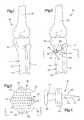
- FIG. 1is a schematic posterior illustration of the relationship between bones in a patient's body
- FIG. 2is a schematic illustration, generally similar to FIG. 1 , illustrating the manner in which a wedge member is utilized to change a spatial relationship between portions of one of the bones of FIG. 1 ;
- FIG. 3is an enlarged plan view, taken generally along the line 3 - 3 of FIG. 2 , illustrating the configuration of the wedge member;
- FIG. 4is a side elevational view, taken generally along the line 4 - 4 of FIG. 3 , further illustrating the configuration of the wedge member;
- FIG. 5is an enlarged schematic fragmentary sectional view of a portion of one of the bones of FIG. 2 and illustrating the relationship of the wedge member to the bone;
- FIG. 6is a plan view, taken generally along the line 6 - 6 of FIG. 5 , further illustrating the relationship of the wedge member to the bone;
- FIG. 7is a schematic fragmentary sectional view, generally similar to FIG. 5 , illustrating the relationship of a second embodiment of the wedge member to the bone;
- FIG. 8is a plan view, taken generally along the line 8 - 8 of FIG. 7 , further illustrating the relationship of the wedge member to the bone;
- FIG. 9is a schematic pictorial illustration depicting the construction of a screw which forms another embodiment of the wedge member.
- FIG. 10is an enlarged sectional view of an embodiment of the wedge member of FIGS. 3-6 which is hollow and contains material to promote bone growth through the wedge member;
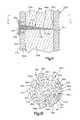
- FIG. 11is a fragmentary schematic sectional view, generally similar to FIG. 5 , illustrating the relationship of another embodiment of the wedge member to the bone;
- FIG. 12is a plan view, taken generally along the line 12 - 12 of FIG. 11 and illustrating the configuration of an opening extending through the wedge member of FIG. 11 ;
- FIG. 13is a schematic fragmentary sectional view, similar to FIGS. 5 , 7 and 11 , illustrating the relationship of a stepped wedge member to a bone;
- FIG. 14is a plan view, taken generally along the line 14 - 14 of FIG. 13 , further illustrating the configuration of the stepped wedge member.
- FIGS. 1 and 2are schematic posterior illustrations of bones in a leg 20 of a patient.
- a tibia bone 22 and fibula bone 24support a femur bone 26 .
- bones 22 , 24 and 26 in a leg of a patienthave been illustrated in FIGS. 1 and 2 , it should be understood that the method and apparatus of the present invention may be used in association with bones in many different portions of a patient's body.
- the upper end portion 30 of the tibia bone 22is angularly misaligned with the lower portion 32 of the tibia bone.
- the upper end portion 30 of the tibia bone 22is offset in a counterclockwise direction by approximately 7 degrees from a desired orientation relative to the lower portion 32 of the tibia bone 22 .
- a wedge member 36FIGS. 2 , 3 and 4 ) is utilized to change the spatial relationship of the upper end portion 30 of the tibia bone 22 relative to the lower portion 32 of the tibia bone.
- the wedge member 36is formed of a relatively hard rigid material.
- the wedge member 36is capable of transmitting force between the upper end portion 30 and the lower portion 32 of the tibia bone 22 . This enables the leg 20 of the patient to be weight bearing as soon as the wedge member 36 is positioned in the tibia bone 22 . Thereafter, bone may grow through the wedge member 36 between the upper end portion 30 and lower portion 32 of the tibia bone 22 .
- the wedge member 36When the wedge member 36 is to be utilized to change the spatial relationship of the upper end portion 30 ( FIG. 2 ) of the tibia bone 22 relative to the lower portion 32 of the tibia bone, an opening is formed in the fleshy part of the body tissue in the leg of the patient to expose the portion of the tibia bone where the wedge member is to be installed. It is contemplated that it may be preferred to install the wedge member 36 approximately two to three millimeters below the upper end of the tibia bone. The specific location where the wedge member 36 is installed will depend upon the surgeon's judgment. It is contemplated that the wedge member 36 may be installed at any one of many locations relative to a particular bone.
- a saw cutis made to form a slot at the location where the wedge member 36 is to be installed.
- the saw cut and resulting slotextend only part way through the tibia bone 22 . This results in the upper end portion 30 of the tibia bone 22 being connected with the lower portion 32 of the tibia bone by a connector or hinge portion 40 ( FIG. 2 ) of the tibia bone.
- the wedge member 36is moved into tie slot.
- a thin edge 44 ( FIGS. 3 and 4 ) of the wedge member 36is leading and a thick edge 46 of the wedge member trailing as the wedge member moves into the slot.
- the wedge member 36pivots the upper end portion of the tibia bone in a clockwise direction (as viewed in FIG. 2 ) relative to the lower portion of the tibia bone about an axis extending through the connector or hinge portion 40 .
- the wedge member 36has an outer side surface 50 ( FIGS. 3 and 4 ) which extends from one end 52 ( FIG. 3 ) of the thin edge 44 of the wedge member 36 along the thick edge 46 of the wedge member to the opposite end 54 of the thin edge 44 .
- the outer side surface 50 of the wedge member 36has the same configuration as the outer side surface of the tibia bone 22 at the location where the saw cut formed the slot between the upper end portion 30 and lower portion 32 of the tibia bone.
- the outer side surface 50 of the wedge membermay be formed in a plurality of sections.
- outer side surface 50 of the wedge member 36has been illustrated schematically in FIG. 3 as forming a portion of a circle, it should be understood that the outer side surface 50 of the wedge member 36 will probably not have a configuration which corresponds to the configuration of a portion of a circle.
- the configuration of the outer side surface 50 of the wedge member 36conforms to the cross sectional configuration of the outside surface of the bone 22 at the location where the wedge member is to be installed in the bone.
- the outer side surface 50 of the wedge member 36has a configuration corresponding to the configuration of the outer side surface of the bone 22 at the location where the wedge member is to be installed in the tibia bone ( FIG. 2 ), the outer side surface 50 ( FIG. 3 ) of the wedge member can be moved into alignment with the outer side surface of the bone 22 .
- Thisenables a hard cortical outer layer of the bone 22 to engage opposite major sides of the wedge member 36 adjacent to the outer side surface 50 of the wedge member.
- the outer layer of hard cortical bonehas continuous engagement with the wedge member 36 from the thin edge 44 to the thick edge 46 of the wedge member. This maximizes the extent of engagement of the hard outer layer of cortical bone with the wedge member 36 to avoid stress concentrations in the hard cortical outer layer.
- the wedge member 36did not have an outer side surface 50 which extended along the outer side surface of the bone 22 from opposite sides of the hinge portion 40 of the bone, the hard cortical outer layer of bone would only be partially supported by the wedge member 36 at the slot in the bone. This would result in the load which is transmitted between the upper end portion 30 of the bone 22 and the lower portion 32 of the bone being concentrated at a relatively small area on the hard cortical outer layer of bone at the opening to the slot.
- the wedge member 36is fixedly connected with the bone.
- suitable screws 58FIG. 2
- mounting strips 60 , 62 and 64FIG. 3
- the mounting strips 60 , 62 and 64 and screws 58hold the wedge member 36 against movement relative to the bone 22 during subsequent loading of the bone by the patient.
- the wedge member 36has a rigid structure, the leg 20 of the patient can be load bearing immediately after closing of the opening which exposed the bone 22 . With she passage of time, bone grows through the wedge member 36 between the upper end portion 30 and lower portion 32 of the bone 22 .
- the wedge member 36( FIGS. 3 and 4 ) has upper and lower major side surfaces 68 and 70 ( FIG. 4 ).
- the upper and lower major side surfaces 68 and 70slope toward each other from the thick edge 46 to the thin edge 44 of the wedge member 36 . It is contemplated that a plurality of wedge members 36 having different acute angles between upper and lower major side surfaces 68 and 70 may be provided. This enables a surgeon to select a wedge member 36 having a desired thickness at the thick edge 46 .
- the acute angle between the flat upper and lower major side surfaces 68 and 70is determined by the extent to which the spatial relationship between the upper end portion 30 and the lower portion 32 ( FIGS. 1 and 2 ) of the bone 22 is to be changed by insertion of the wedge member 36 .
- the larger the bone with which the wedge member 36 is usedthe smaller is the angle between the upper and lower major side surfaces 66 and 68 to obtain a desired thickness of the wedge member at the thick edge 46 of the wedge member.
- the angle between the upper and lower major side surfaces 68 and 70may be within a range between one degree and twenty degrees. Although the specific angle provided between the upper and lower major side surfaces 68 and 70 will depend upon the environment in which the wedge member is to be utilized, it is believed that the angle between the upper and lower major side surfaces 68 and 70 may frequently be between two degrees and ten degrees. It should be understood that the foregoing specific ranges of sizes for the angle between the upper and lower major side surfaces 68 and 70 have been set forth herein for purposes of clarity of description and it is contemplated that the angle between the upper and lower major side surfaces may be any one of many angles other than these specific angles.
- the wedge member 36may be formed of any one of many different known materials which are compatible with a patient's body.
- the wedge membermay be formed of human or animal bone, stainless steel, tantalum, a porous ceramic, or a polymeric material.
- the wedge member 36may be formed of a biodegradable material.
- the wedge member 36is porous so that bone can grow through the wedge member.
- the wedge member 36has a plurality of openings or passages 74 which extend through the wedge member between the upper and lower major side surfaces 68 and 70 .
- the openings 74enable bone to grow through the wedge member 36 .
- the wedge member 36may have a cellular construction similar to coral. Alternatively, straight passages may be drilled or cast in the wedge member 36 . It is contemplated that the wedge member 36 may be coated with a material which promotes the growth of bone. If the wedge member 36 has a cellular construction, the cells may be at least partially filled with bone growth promoting material.
- a location for insertion of the wedge memberis selected by a surgeon. It is contemplated that it may be desired to locate the wedge member 36 approximately two to five millimeters below the upper end of the tibia bone. However, the specific location at which the wedge member is inserted into the bone 22 will be selected by the surgeon as a function of the result desired from a particular operation.
- a saw slotis formed at the location where the wedge member is to be inserted into the bone.
- the slotextends only part way through the bone.
- the slotextended from the left side of the tibia bone 22 toward the right side to a location which was spaced from the right side of the tibia bone.
- the thickness of the hinge portion 40will depend upon the location where the wedge member is being installed, the extent to which the spatial relationship between portions of the bone are to be changed by insertion of the wedge member, and the physical characteristics of the bone itself.
- the wedge member 36is moved into the slot.
- the thin edge 44 of the wedge memberis easily inserted into an entry opening to the slot. Force is then applied against the thick edge 46 of the wedge member to move the wedge member further into the slot.
- the thin edge 44 of the wedge member 36When the thin edge 44 of the wedge member 36 is initially positioned in the slot, the thin edge of the wedge member is diametrically opposite from the hinge portion 40 of the bone 22 .
- a longitudinal axis of the thin edge 44that is an axis extending between the opposite ends 52 and 54 ( FIG. 3 ) of the thin edge, is parallel to the bottom of the slot when the thin edge is initially positioned in the slot.
- an axis perpendicular to the thin edge 44 and extending through the center of the wedge member 36is aligned with an axis extending perpendicular to the bottom of inner edge of the slot and extending through the center of the bone 22 .
- the wedge member 36is then moved into the slot along a linear path which extends perpendicular to the bottom or inner end of the slot and to the thin edge 44 of the wedge member.
- the upper major side surface 68FIGS. 4 and 5
- the lower major side surface 70 of the wedge memberslides along and applies force against the lower portion 32 of the tibia bone 22 .
- the wedge member 36is moved into the slot under the influence of force applied against the trailing thick edge portion 46 .
- the wedge member 36could be mounted at many different locations in many different types of bone, the wedge member 36 is illustrated in FIGS. 5 and 6 as being positioned in the tibia bone 22 at a location in which an outer layer 80 of hard cortical bone extends around a core 90 of soft cancellous bone.
- the central portion of the thin leading edge 44engages the outer layer 80 of hard cortical bone at the entry to the slot on a side of the bone 22 opposite from the hinge or connector portion 40 .
- Forceis applied against the outer layer 80 of hard cortical bone by the upper and lower major side surfaces 68 and 70 of the wedge member 36 at a location adjacent to the center of the opening to the slot.
- the force applied against the outer layer 80 of hard cortical bone by the thin leading end portion of the wedge member 36initiates pivotal movement of the upper end portion 30 of the bone 22 about an axis extend through the hinge portion 40 .
- the area of engagement of the thin leading edge 44 of the wedge member with the outer layer 80 of hard cortical bonemoves outward from a central portion of the thin leading edge 44 toward the opposite ends 52 and 54 of the thin leading edge 44 ( FIGS. 3 and 6 ).
- the upper and lower major sides 68 and 70 of the wedge membermove into engagement with the layer 80 of hard cortical bone along opposite sides of the bone 22 .
- the central portion of the thin edge 44engages the core 90 of soft cancellous bone.
- the central portion of the thin edge 44 of the wedge member 36engages the core 90 of soft cancellous boner portions of the thin edge 44 on opposite sides of the central portion of the thin edge are in engagement with the outer layer 80 of hard cortical bone.
- the central portion of the thin edge 44may or may not engage the core 90 of soft cancellous bone before the opposite ends 52 and 54 of the thin edge 44 of the wedge member 36 move into initial engagement with the outer layer 80 of hard cortical bone.
- the upper and lower major side surfaces 68 and 70 of the wedge member 36are sliding along the portion of the outer layer 80 of hard cortical bone disposed behind the thin leading edge 44 of the wedge member 36 , that is, to the left as viewed in FIGS. 5 and 6 .
- the upper portion 30 of the bonepivoted relative to the lower portion 32 by force applied against the upper and lower portions of the bone by the wedge member 36 .
- the upper end portion 30 of the bone 22is pivoted relative to the lower portion 32 of the bone about an axis extending parallel to the thin leading edge 44 of the wedge member 36 and extending through the connector or hinge portion 40 of the bone 22 .
- the outer side surface 50 on the wedge member 36When the outer side surface 50 on the wedge member 36 is moved into alignment with the outer side surface 94 on the bone 22 , the outer side surface 50 on the wedge member 36 will form a continuation of the outer side surface 94 of the bone 22 . Although perfect alignment of the outer side surface 50 of the wedge member 36 with the outer side surface 94 of the bone is desired, there may be a slight misalignment or discontinuity where the outer side surface 50 of the wedge member 36 is aligned with the outer side surface 94 of the bone 22 .
- the wedge member 36has been shown as being formed as a portion of a circle with the thin edge 44 being a chord of the circle.
- the wedge member 36it is believed that it will be preferred to form the wedge member 36 with a configuration which matches the configuration of the bone 22 in which the wedge member is to be inserted.
- the bone 22may have an irregular outer side surface 94 which is not formed as a portion of a circle.
- the outer side surface 50 of the wedge member 36would have a matching irregular configuration and would not be formed as a portion of a cylinder.
- the outer side surface 50 of the wedge member 36By having the outer side surface 50 of the wedge member 36 have a configuration which is the same as the configuration as the outer surface 94 of the bone 22 , almost perfect alignment can be obtained between the wedge member 36 and the bone 22 . Although there may be some misalignment of the wedge member 36 and outer side surface 94 of the bone 22 , the outer layer 80 of hard cortical bone is disposed in engagement with the upper and lower major side surfaces 68 and 70 of the wedge member 36 adjacent to the outer side surface 50 of the wedge member throughout the extent of the outer side surface of the wedge member.
- the area for transmittal of force between the upper and lower major side surfaces 68 and 70 ( FIG. 5 ) of the wedge member and the outer layer 80 of hard cortical boneis maximized. This is because the entire extent of the outer layer 80 of cortical bone which has been cut to form the slot is disposed in engagement with the wedge member 36 .
- the only portion of the outer layer 80 of hard cortical bone which does not engage the wedge member 36is the portion of the outer layer of hard cortical bone which is disposed in the connector or hinge portion 40 of the tibia bone 22 ( FIGS. 5 and 6 ). Therefore, there is no open space between surfaces on the outer layer 80 of hard cortical bone where the slot was formed. This minimizes any tendency for stress concentrations to occur due to insertion of the wedge member 36 into the bone 22 .
- the outer side surface 50 of the wedge member 36is considered as being aligned with the outer side surface 94 of the bone 22 when there is a slight discontinuity between the outer side surface 94 of the bone and the outer side surface 50 of the wedge member 36 .
- the extent of this discontinuityshould be minimized.
- Close alignment of the outer side surface 50 of the wedge member 36 with the surface 94 on the bone 22maximizes the extent of engagement of the outer layer 80 of hard cortical bone with the wedge member.
- close alignment of the outer side surface 50 of the wedge member 36 with the surface 94 on the bone 22minimizes the extent to which the wedge member projects outward from the outer side surface of the bone.
- the screws 58are used to fixedly connect the wedge member 36 with the upper end portion 30 and lower portion 32 of the bone 22 .
- the screws 58engage the outer layer of hard cortical bone ( FIG. 5 ) to hold the wedge member 36 against movement relative to the borne 22 . It is contemplated that the wedge member 36 could be connected with the bone 22 in a manner other than by using screws 58 .
- the wedge member 36Since the wedge member 36 is rigid, it can immediately transmit loads between the upper end portion 30 and lower portion 32 of the tibia bone 22 . Therefore, after the incision which exposed the site at which the wedge member 36 is inserted into the bone 22 has been closed, the patient can begin to apply weight to the leg 20 . This weight will be transmitted through the entire extent of the outer layer 80 of hard cortical bone. Thus, the portion of the outer layer 80 of hard cortical bone in the connector or, hinge portion 40 of the tibia bone 22 is not severed and can transmit force in the usual manner. The portion of the outer layer 80 of hard cortical bone which was cut to form the slot into which the wedge 36 was inserted, engages the upper and lower major side surfaces 68 and 70 of the wedge member 36 . Since the wedge member 36 is rigid, force can be transmitted between the portions of the outer layer 80 of hard cortical bone which engage the wedge member.
- the central portion of the wedge member 36engages the core 90 of soft cancellous bone. Since the wedge member 36 is porous, the soft cancellous bone can grow through openings formed in the wedge member 36 to fuse the upper end portion 30 and lower portion 32 of the bone 22 .
- the growth of the soft cancellous bone through the wedge member 36may be promoted by coating the wedge member with known bone growth inducing substances.
- the hard cortical bone of the outer layer 80will eventually grow through openings 74 in the wedge member 36 .
- the openings 74which extend through the wedge member 36 , may have a straight cylindrical configuration or may have an irregular configuration, similar to the configuration of openings or cavities formed in natural coral.
- the wedge member 36is positioned in bone 22 at a location where an outer layer 80 of hard cortical bone extends around a core 90 of soft cancellous bone.
- the wedge member 36could be used at locations where one or both major side surfaces 68 and 70 are engaged by only hard cortical bone.
- the wedge member 36has been illustrated in FIG. 2 being used in a bone 22 in a patient's leg 20 , the wedge member could be used with other bones.
- the wedge member 36could be used in association with bones in a patient's arm, wrist, hand, ankle or foot.
- the openings 74 aare provided in the wedge member 36 a to enable bone to grow through the wedge member. If desired, the openings 74 a could be omitted.
- the wedge member 36 illustrated in FIGS. 2-6the wedge member is pushed into a slot formed in the bone 22 by the application of force against the thick edge 46 of the wedge member.
- a long thin screw memberis utilized to guide at least a portion of the movement of the wedge member into the bone and to apply force to the wedge member to pull the wedge member into the slot formed in the bone. Since the embodiment of the invention illustrated in FIGS. 7 and 8 is generally similar to the embodiment of the invention illustrated in FIGS. 2-6 , similar numerals will be utilized to designate similar components, the suffix letter “a” being associated with the numerals of FIGS. 7 and 8 to avoid confusion.
- a wedge member 36 ais inserted into a bone 22 a to change the spatial relationship of an upper portion 30 a ( FIG. 7 ) of the bone relative to a lower portion 32 a of the bone.
- the wedge member 36 ahas a thin edge 44 a and a thick edge 46 a .
- An outer side surface 50 a( FIG. 8 ) extends between opposite ends 52 a and 54 a of the thin edge 44 a ( FIG. 8 ).
- Upper and lower major side surfaces 68 a and 70 a( FIG. 7 ) extend between the thin edge 44 a and the thick edge 46 a .
- the flat upper and lower major side surfaces 68 a and 70 aare skewed at an acute angle relative to each other.
- Openings 74 aextend through the wedge member 36 a to enable bone to grow through the wedge member.
- the opening 74 amay have a straight cylindrical configuration or may have an irregular configuration, similar to openings formed in natural coral.
- the wedge member 36 amay be coated with bone growth promoting material and/or the openings 74 a filled with bone growth promoting material. If desired, the openings 74 a may be omitted.
- a plurality of mounting strips 60 a , 62 a and 64 aengage an outer side surface 94 a of the bone 22 a .
- Suitable fasteners 58 aconnect the wedge member 36 a with the bone 22 a .
- the outer side surface 50 a or the wedge member 36 ais aligned with the outer side surface 94 a of the bone 22 a.
- the wedge member 36 ahas the same general construction as the wedge member 36 of FIGS. 1-6 .
- the wedge member 36 ais inserted into a slot formed in the bone 22 a in much the same manner as previously described in connection with the embodiment of the invention illustrated in FIGS. 1-6 .
- a screw member 100is utilized to guide movement of the wedge member 36 a relative to the bone 22 a and to apply force to the wedge member 36 a to pull the wedge member into a slot formed in the bone 22 a.
- the screw member 100has a straight elongated shank 102 ( FIG. 7 ) which extends through the wedge member 36 a .
- a head end portion 104 of the screw member 100is fixedly connected with the shank 102 and disposed in a suitable recess formed in the wedge member 36 a .
- An opening 106is formed in the mounting strip 62 a to provide access to the head end portion 104 of the screw member 100 .
- the screw member 100has en externally threaded end portion 110 disposed on the end of the shank 102 opposite from the head end portion 104 .
- the externally threaded end 110 of the screw member 100is engageable with the outer layer 80 a of hard cortical bone at the hinge or connector section 40 a of the bone 22 a.
- the wedge member 36 aWhen the wedge member 36 a is to be inserted into a slot in the bone 22 a , the wedge member 36 a is moved into the slot in the manner previously explained in conjunction with the embodiment of the invention illustrated in FIGS. 2-6 . As the wedge member 36 a approaches the position shown in FIG. 7 , the externally threaded end 110 of the screw member 100 engages an inner side surface 114 of the outer layer 80 a of hard cortical bone. The head end portion 104 of the screw member 100 is then rotated. This causes the externally threaded end portion 110 of the screw member to move into threaded engagement with the outer layer 80 a of hard cortical bone.
- the wedge member 36 ahas been illustrated in FIGS. 7 and 8 at a location where a layer 80 a of hard cortical bone encloses a core 90 a of soft cancellous bone, the wedge member 36 a could be used at a location where the wedge member engages only hard cortical bone. Although it is preferred to provide the openings 74 a to enable bone to grow through the wedge member 36 a , the openings may be omitted if desired.
- the wedge memberhas flat major side surfaces which extend from a relatively thick edge 46 of the wedge member to a relatively thin edge 44 of the wedge member.
- the wedge memberis formed as an axially tapered screw. Since the wedge member of the embodiment of the invention illustrated in FIG. 9 changes the spatial relationship between end portions of a bone in a patient's body in a manner similar to that explained in conjunction with the embodiments of the invention illustrated in FIGS. 2-7 , similar numerals will be utilized to identify components of the embodiment of the invention illustrated in FIG. 9 , the suffix letter “b” being associated with the numerals of FIG. 9 to avoid confusion.
- a wedge member 36 bhas a thin edge or point 44 b and a thick edge or head 46 b ( FIG. 9 ).
- a mounting strip 62 bis connected with the thick edge 46 b and engages an outer side surface of a bone to limit movement of the wedge member 36 b relative to the bone.
- a side surface 50 b on the thick edge 46 b of the wedge member 36 bis aligned with an outer side surface of the bone when the mounting strip 62 b engages the outer side surface of the bone.
- the wedge member 36 bhas a spiral external thread convolution 116 .
- the thread convolution 116has a generally conical configuration and tapers from the thick edge 50 b of the wedge member 36 b to the thin edge or point 44 b of the wedge member 36 b.
- a slotis formed in the bone in the same manner as previously explained in conjunction with the embodiment of the invention illustrated in FIGS. 2-8 .
- the wedge member 36 bis then screwed into the slot.
- forcemay be applied to the mounting strip 62 b to rotate the wedge member 36 b about its longitudinal central axis.
- a socketmay be provided in the thick edge 46 b to receive a suitable tool which transmits torque to the wedge member 36 b.
- the external thread convolution 116 on the wedge member 36 bcooperates with the hard cancellous outer layer of the bone to effect axial movement of the wedge member into the slot in the bone.
- the portion of the bonecorresponding to the upper end portion 30 of FIG. 2 , pivots relative to a lower portion 32 . This results in a change in the spatial relationship between the upper portion and lower portion of the bone.
- a longitudinal central axis of the wedge memberPrior to moving the wedge member 36 b into the slot in the bone, a longitudinal central axis of the wedge member is aligned with an axis which is perpendicular to a bottom of the slot and extends through the center of the bone.
- the wedge member 36 bis then rotated about its longitudinal central axis.
- the wedge membermoves along a straight path which extends perpendicular to an axis about which the upper end portion of the bone is pivoted relative to the lower portion of the bone. Movement of the wedge member 36 b into the slot is interrupted with the thin edge or point 44 b spaced from a connector or hinge portion of the bone which interconnects the upper end portion and lower portion of the bone.
- a plurality of openings 74 bare formed in the wedge member 36 b to enable bone to grow through the wedge member in the manner previously explained in conjunction with the embodiment of FIGS. 1-8 .
- the wedge member 36 bis coated with a bone growth promoting material.
- the wedge member 36 bmay be hollow to provide a cavity to hold bone growth promoting material.
- the wedge memberhas openings to enable bone to grow through the wedge member.
- the wedge memberis hollow to provide a cavity which holds bone growth promoting material. Since the embodiment of the invention illustrated in FIG. 10 is generally similar to the embodiment of the invention illustrated in FIGS. 2-9 , similar numerals will be utilized to designate similar components, the suffix letter “c” being associated with the embodiment of FIG. 10 to avoid confusion.
- a wedge member 36 c( FIG. 10 .) has a thin edge 44 c and a thick edge 46 c .
- An outer side surface 50 cextends between opposite ends of the thin edge 44 c in the same manner as is illustrated in FIGS. 3 and 6 for the embodiment of the invention of FIGS. 2-6 .
- the wedge member 36 chas the same overall configuration as the wedge member 36 of FIGS. 2-6 .
- a mounting strip 62 cis connected with the thick edge 44 c of the wedge member 36 c .
- Additional mounting stripscorresponding to the mounting strips 60 and 64 of the embodiment of the invention illustrated in FIGS. 3 and 6 , are provided on the wedge member 36 c .
- the mounting strip 62 cengages the outer side surface of the bone. Suitable fasteners may be used to interconnect the bone and the mounting strip 62 c .
- FIG. 10Although only a single mounting strip 62 c has been illustrated in FIG. 10 , it should be understood that additional mounting strips, corresponding to the mounting strips 62 and 64 of FIG. 3 , are associated with the wedge member 36 c.
- the wedge member 36 chas a flat upper major side surface 68 c and a flat lower major side surface 70 c .
- the upper and lower major side surfaces 68 c and 70 chave the same configuration as the upper and lower major side surfaces 68 and 70 of the embodiment of the invention illustrated in FIGS. 2-6 .
- the outer side surface 50 chas the same configuration as the outer side surface 50 of the embodiment of the invention illustrated in FIGS. 2-6 .
- the upper and lower major side surfaces 68 c and 70 c( FIG. 10 ) are disposed at an acute angle and taper from the thick edge 46 c to the thin edge 44 c of the wedge member 36 c.
- the wedge member 36 cis rigid to enable it to be weight bearing as soon as it is positioned in a bone.
- the wedge member 36 ccould be formed of many different materials, it is formed of stainless steel.
- the wedge member 36 c( FIG. 10 ) is hollow. Therefore, a compartment or cavity 120 is formed in the wedge member 36 c .
- the compartment 120has upper and lower inner side surfaces 122 and 124 which are smaller than the upper and lower major side surfaces 68 c and 70 c of the wedge member 36 c .
- the inner side surfaces 122 and 124 of the compartment 120have the same general configuration as the upper and lower major side surfacers 68 c and 70 c of the wedge member 36 c.
- the compartment 120is filled with a bone growth inducing material 130 .
- the bone growth inducing material 130is (not shown) formed in either the upper major side surface 68 c or the lower major side surface 70 c of the wedge member 36 c .
- the growth of bone through the wedge member 36 cis promoted by the bone growth inducing material 130 in the compartment 120 .
- the bone growth inducing material 130 in the compartment 120may be any one of many known compositions. For example, apatite compositions with collagen may be utilized. Demineralized bone powder may also be utilized. Regardless of which of the known bone growth inducing materials are selected, the presence of the bone growth inducing material in the compartment 120 will promote a growth of bone through the openings 74 c in the wedge member 36 c.
- the wedge member 36 cmay, itself, be formed of a suitable rigid material, such as tantalum or stainless steel. In addition to the bone growth inducing material 130 in the compartment 120 , the surfaces of the wedge member 36 c and the openings 74 c may be coated with suitable bone growth inducing materials. Although the wedge member 36 c has been shown as having straight cylindrical openings 74 c through which bone grows, the wedge member 360 could have an open celled construction if desired.
- a plurality of relatively small openings 74extend through the various wedge members to enable bone to grow through the wedge members.
- a relatively large central openingis provided in the wedge member to enable bone to grow through the wedge member. Since the embodiment of the invention illustrated in FIGS. 11 and 12 is generally similar to the embodiment of the invention illustrated in FIGS. 2-10 , similar numerals will be utilized to designate similar components, the suffix letter “d” being associated with the numerals of FIGS. 11 and 12 to avoid confusion.
- a wedge member 36 d( FIGS. 11 and 12 ) has a thin edge 44 d and a thick edge 46 d .
- An outer side surface 50 dextends between opposite ends 52 d and 54 d ( FIG. 12 ) of the thin edge 44 d .
- the outer side surface 50 dhas a configuration which corresponds to the configuration of an outer side surface 94 d of a bone 22 d ( FIG. 11 ).
- the wedge member 36 dhas flat upper and lower major side surfaces 68 d and 70 d which are skewed at an acute angle relative to each other and extend between the thin edge 44 d and the thick edge 46 d of the wedge member 36 d.
- the wedge member 36 dhas the same overall configuration as the wedge member 36 of the embodiment of the invention illustrated in FIGS. 2-6 .
- the side surface 50 d( FIG. 12 ) has the same configuration as the side surface 50 of FIGS. 3 and 4 .
- the upper and lower major side surfaces 68 d and 70 d( FIGS. 11 and 12 ) have outer edge portions with the same configuration as the outer edge portion of the major side surfaces 68 and 70 of FIGS. 3 and 4 .
- mounting strips 60 d , 62 d , and 64 d on the wedge member 36 dmove into abutting engagement with the outer side surface 94 d of the bone 22 d ( FIG. 17 ).
- the mounting strips 60 d , 62 d , and 64 dare fixedly connected with the upper end portion 30 d and lower portion 32 d of the bone 22 d by suitable fasteners 58 d .
- the fasteners 58 dretain the wedge member 36 d against movement from a position in which the side surface 50 d is aligned with the outer side surface 94 d of the bone 22 d.
- an upper portion 30 d ( FIG. 11 ) of the bone 22 dis pivoted relative to a lower portion 32 d to change the spatial relationship between the upper portion 30 d and lower portion 32 d of the bone 22 d .
- the upper portion 30 d of the bone 22 dpivots about an axis which extends parallel to the thin edge 44 d of the wedge member 36 d .
- the axis about which the upper portion 30 d of the bone pivotsextends through the hinge or connector portion 40 d of the bone 22 d and is parallel to the bottom of the slot formed in the bone 22 d to receive the wedge member 36 d.
- the wedge member 36 dhas a large central opening 134 through which bone may grow.
- the openings 134extends between upper and lower major side surfaces 68 d and 70 d of the wedge member 36 d .
- the opening 134is configured in such a manner that the upper and lower major side surfaces 68 d and 70 d of the wedge member 36 d engage an outer layer 80 d of hard cortical bone throughout movement of the wedge member 36 d into the slot formed in the bone 22 d.
- the large opening 134enables the core 90 d of soft cancellous bone to easily grow through the wedge member 36 d .
- material 130 dFIG. 11
- the outer layer 80 d of hard cortical boneis disposed in abutting engagement with opposite major side surfaces 68 d and 70 d on the wedge member 36 d throughout the extent of the opening to the slot into which the wedge member is inserted.
- Relatively small openings 74 dare provided in the wedge member 36 d to enable hard cortical bone to grow through the wedge member.
- the opening 134has a configuration which is similar to but smaller than the overall configuration of the wedge member 36 d .
- the opening 134has a flat, rectangular side surface 136 which extends parallel to the thin edge 44 d of the wedge member 36 d .
- the opening 134has an arcuate side surface 138 which is spaced substantially the same distance from the outer side surface 50 d throughout the extent of the side surface 138 of the opening 134 and the side surface 50 d of the wedge member 36 d.
- the side surface 138 of the opening 134is spaced from the outer side surface 50 d by a distance which is greater than the thickness of the outer layer 80 d of hard cortical bone. Therefore, as the wedge member 36 d is inserted into the slot formed in the bone 22 d , the outer layer 80 d of hard cortical bone engages the upper and lower major side surfaces 58 d and 70 d of the wedge member 36 d .
- the outer layer 80 d of hard cortical boneis in engagement with the upper and lower major side surfaces 68 d and 70 d of the wedge member 36 d when the outer side surface 50 d of the wedge member is aligned with the outer side surface 94 d of the bone 22 d .
- the outer layer 80 d of hard cortical boneis disposed in engagement with the wedge member 36 d throughout the extent of the opening to the slot into which the wedge member 36 d is inserted.
- the mounting strips 60 d , 62 d and 64 dmove into abutting engagement with the outer side surface 94 d of the bone.
- Suitable fasteners 58 dcan then be utilized to connect the wedge member 36 d with the upper end portion 30 d and the lower portion 32 d of the bone 22 d .
- the fasteners 58 dmaintain the outer side surface 50 d on the wedge member 36 d in alignment with the outer side surface 94 d of the bone 22 d.
- the wedge member 36 dcan, upon being positioned relative to the bone and an incision which was made to expose the bone closed, be load bearing. This is because the outer layer 80 d of hard cortical bone extends through the hinge portion 40 d and can support a load in the usual manner.
- the outer layer 80 d of hard cortical boneis disposed in engagement with the upper and lower major side surfaces 68 d and 70 d of the rigid wedge member 36 d at a location offset to the left (as viewed in FIG. 12 ) from the hinge on connector portion 40 d . Therefore, force can be transmitted between the upper end portion 30 d and lower portion 32 d ( FIG. 11 ) through the wedge member 36 d as soon as the wedge member has been properly installed in the bone 22 d.
- the soft cancellous bone 90 dgrows through and completely fills the opening 134 in the wedge member 36 d .
- the opening 134could have any desired configuration.
- the wedge member 36 dcould be coated with bone growth promoting material. If desired, the small openings 74 d could be omitted.
- the wedge memberhas flat major side surfaces.
- the wedge memberhas major side surfaces with a stepped configuration. Since the embodiment of the invention illustrated in FIGS. 13 and 14 is generally similar to the embodiment of the invention illustrated in FIGS. 2-6 , similar numerals will be utilized to identify similar components, the suffix letter “e” being associated with the numerals of FIGS. 13 and 14 to avoid confusion.
- a wedge member 36 eis used to change a spatial relationship between an upper end portion 30 e and a lower portion 32 e of a bone 22 e ( FIG. 13 ).
- the wedge member 36 eincludes a thin edge 44 e and a thick edge 46 e .
- the wedge member 36 ehas an outer side surface 50 e which extends between opposite ends 52 e and 54 e ( FIG. 14 ) of the thin edge 44 e .
- the wedge member 36 ehas an upper major side 68 e ( FIG. 13 ) and a lower major side 70 e.
- a plurality of mounting strips 60 e , 62 e and 64 emove into abutting engagement with an outer side surface 94 e of the bone 22 e when the wedge member 36 e is inserted into a slot formed in the bone in the manner previously explained.
- the upper end portion 30 e of the bone 22 epivots about an axis which extends through a connector or hinge portion 40 e of the bone.
- the axis about which the upper portion 30 e of the bone pivotsextends parallel to the thin edge 44 e of the wedge member 36 e.
- the outer side surface 50 eis in alignment with the outer side surface 94 e of the bone 22 e .
- Suitable fasteners 58 eare utilized to connect the wedge member 46 e with the upper end portion 30 e and lower portion 32 e of the bone 22 e in the manner previously explained.
- the upper major side 68 e of the wedge member 36 ehas a stepped configuration.
- the upper major side 68 e of the wedge member 36 eincludes a flat surface area 150 ( FIGS. 13 and 14 ) which extends at a first, relatively small acute angle relative to the lower major side surface 70 e of the wedge member 36 e .
- a second surface area 152extends from the surface area 150 toward the outer side surface 50 e of the wedge member 36 e at a second acute angle relative to the lower side surface 70 e .
- the second acute angle, at which the side surface 152 extends relative to the lower side surface 70 e ( FIG. 13 )is greater than the first angle at which the side surface area 150 extends relative to the lower side surface 70 e.
- the wedge member 36 eincludes a surface area 154 which extends outward from the surface area 152 to the outer side surface 50 e of the wedge member 36 e .
- the surface 154slopes at an acute angle relative to the lower side surface 70 e of the wedge member 36 e .
- the angle which the surface 154 makes with the dower side surface 70 eis greater than the angle which the surface area 150 makes with the lower side surface 70 e .
- the angle which the surface area 150 makes with the lower side surface 70 e of the wedge member 36 eis less than the angle which the surface area 152 makes with the lower side surface 70 e ( FIG. 13 ).
- the surface area 154extends a substantially constant distance from the outer side surface 50 e of the wedge member 36 e throughout the extent of the surface area 154 ( FIG. 14 ). Since the surface area 152 extends between the surface area 150 and the surface area 154 ( FIG. 14 ) the extent of the surface area 152 varies as a function of the distance of the surface area from a perpendicular to the thin edge 44 e and through the center of wedge member 36 e . The resulting stepped configuration of the wedge member 36 e facilitates initial movement of the wedge member into the slot formed in the bone 22 e.
- a plurality of openings 74 eextend through the wedge member 36 e .
- the openings 74 eenable bone to grow through the wedge member 36 e
- the openings 74 emay have a straight cylindrical configuration or may have an open-celled structure.
- the wedge member 36 emay be coated with bone growth promoting material and/or the openings 74 e may be at least partially filled with bone growth promoting material.
- An outer layer 80 e of hard cortical boneis disposed in engagement with the surface area 154 adjacent to the outer side surface 50 e of the wedge member 36 e .
- the portion of the outer layer 80 e of hard cortical bone exposed by formation of the slot in the bonealso engages the lower major side surface 70 e of the wedge member 36 e .
- the wedge member 36 eis formed of a rigid material which is capable of transmitting force between the upper end portion 30 e and the lower portion 32 e of the bone 22 e . Therefore, the bone is immediately weight supporting when the wedge member 36 e is positioned in the bone in the manner illustrated in FIGS. 13 and 14 .
- the present inventionprovides a new and improved method and apparatus for use in changing a spatial relationship between portions of a bone 22 in a patient's body.
- an openingis formed in a portion of the patient's body tissue to at least partially expose the bone 22 .
- Forceis applied to the bone 22 with a wedge member 36 to move one portion 30 of the bone relative to another portion 32 of the bone.
- the wedge member 36may be fixedly connected with either or both portions of the bone.
- the opening in the patient's bodyis then closed with the wedge member 36 disposed in engagement with the bone 22 . Force can be transmitted between portions 30 and 32 of the bone 22 through the wedge member 36 .
- the wedge member 36may taper from a thick edge 46 to a thin edge 44 and have a side surface 50 which extends from one end 52 of the thin edge, along the thick edge, to the opposite end 54 of the thin edge.
- the side surface 50 of the wedge member 36has a cross sectional configuration corresponding to the configuration of a portion of an outer side surface 94 of the bone 22 . This enables the wedge member 36 to be aligned with the outer side surface 94 of the bone 22 .
- the wedge member 36may be positioned relative to the bone 22 at a location where a layer 80 of hard cortical bone encloses soft cancellous bone 90 . Opposite ends 52 and 54 of the thin edge 44 of the wedge member 36 may be positioned in engagement with the hard cortical bone 80 while a central portion of the thin edge 44 of the wedge member 36 engages the soft cancellous bone. In addition, the layer 80 of hard cortical bone may engage the wedge member 36 adjacent to the side surface 50 of the wedge member.
- the wedge member 36may have many different constructions. It is believed that it will be advantageous to form the wedge member 36 with one or more openings 74 through which bone can grow.
- the wedge member 36may be hollow and contain material 130 which promotes the growth of bone through the wedge member.
- a screw member 100may extend ahead of the thin leading edge 44 of the wedge member 36 and engage hard cortical bone. Force may be transmitted from the screw member 100 to the wedge member 36 to move the wedge member relative to the bone.
- the wedge member 36may have a circular cross sectional configuration with an external thread convolution 116 to enable the wedge member to be moved into an opening in a bone by rotating the wedge member.
Landscapes
- Health & Medical Sciences (AREA)
- Orthopedic Medicine & Surgery (AREA)
- Life Sciences & Earth Sciences (AREA)
- Surgery (AREA)
- Animal Behavior & Ethology (AREA)
- Veterinary Medicine (AREA)
- Public Health (AREA)
- Engineering & Computer Science (AREA)
- Biomedical Technology (AREA)
- Heart & Thoracic Surgery (AREA)
- General Health & Medical Sciences (AREA)
- Molecular Biology (AREA)
- Medical Informatics (AREA)
- Nuclear Medicine, Radiotherapy & Molecular Imaging (AREA)
- Neurology (AREA)
- Cardiology (AREA)
- Oral & Maxillofacial Surgery (AREA)
- Transplantation (AREA)
- Vascular Medicine (AREA)
- Surgical Instruments (AREA)
- Prostheses (AREA)
Abstract
Description
Claims (85)
Priority Applications (4)
| Application Number | Priority Date | Filing Date | Title |
|---|---|---|---|
| US13/847,325US8795363B2 (en) | 1998-06-30 | 2013-03-19 | Wedge apparatus for use in operating on a bone |
| US14/445,784US9044322B2 (en) | 1998-06-30 | 2014-07-29 | Method and apparatus for use in operating on a bone |
| US14/572,980US9050152B2 (en) | 1998-06-30 | 2014-12-17 | Method and apparatus for use in operating on a bone |
| US14/729,768US20150265326A1 (en) | 1998-06-30 | 2015-06-03 | Method and apparatus for use in operating on a bone |
Applications Claiming Priority (5)
| Application Number | Priority Date | Filing Date | Title |
|---|---|---|---|
| US09/109,126US6086593A (en) | 1998-06-30 | 1998-06-30 | Method and apparatus for use in operating on a bone |
| US09/566,070US6575982B1 (en) | 1998-06-30 | 2000-05-05 | Method and apparatus for use in operating on a bone |
| US10/438,705US8486066B2 (en) | 1998-06-30 | 2003-05-15 | Spacer |
| US11/928,400US8690944B2 (en) | 1998-06-30 | 2007-10-30 | Wedge apparatus for use in operating on a bone |
| US13/847,325US8795363B2 (en) | 1998-06-30 | 2013-03-19 | Wedge apparatus for use in operating on a bone |
Related Parent Applications (1)
| Application Number | Title | Priority Date | Filing Date |
|---|---|---|---|
| US11/928,400ContinuationUS8690944B2 (en) | 1998-06-30 | 2007-10-30 | Wedge apparatus for use in operating on a bone |
Related Child Applications (1)
| Application Number | Title | Priority Date | Filing Date |
|---|---|---|---|
| US14/445,784ContinuationUS9044322B2 (en) | 1998-06-30 | 2014-07-29 | Method and apparatus for use in operating on a bone |
Publications (2)
| Publication Number | Publication Date |
|---|---|
| US20130226311A1 US20130226311A1 (en) | 2013-08-29 |
| US8795363B2true US8795363B2 (en) | 2014-08-05 |
Family
ID=22325929
Family Applications (8)
| Application Number | Title | Priority Date | Filing Date |
|---|---|---|---|
| US09/109,126Expired - LifetimeUS6086593A (en) | 1998-06-30 | 1998-06-30 | Method and apparatus for use in operating on a bone |
| US09/566,070Expired - LifetimeUS6575982B1 (en) | 1998-06-30 | 2000-05-05 | Method and apparatus for use in operating on a bone |
| US10/438,705Expired - Fee RelatedUS8486066B2 (en) | 1998-06-30 | 2003-05-15 | Spacer |
| US11/928,400Expired - Fee RelatedUS8690944B2 (en) | 1998-06-30 | 2007-10-30 | Wedge apparatus for use in operating on a bone |
| US13/847,325Expired - Fee RelatedUS8795363B2 (en) | 1998-06-30 | 2013-03-19 | Wedge apparatus for use in operating on a bone |
| US14/445,784Expired - Fee RelatedUS9044322B2 (en) | 1998-06-30 | 2014-07-29 | Method and apparatus for use in operating on a bone |
| US14/572,980Expired - Fee RelatedUS9050152B2 (en) | 1998-06-30 | 2014-12-17 | Method and apparatus for use in operating on a bone |
| US14/729,768AbandonedUS20150265326A1 (en) | 1998-06-30 | 2015-06-03 | Method and apparatus for use in operating on a bone |
Family Applications Before (4)
| Application Number | Title | Priority Date | Filing Date |
|---|---|---|---|
| US09/109,126Expired - LifetimeUS6086593A (en) | 1998-06-30 | 1998-06-30 | Method and apparatus for use in operating on a bone |
| US09/566,070Expired - LifetimeUS6575982B1 (en) | 1998-06-30 | 2000-05-05 | Method and apparatus for use in operating on a bone |
| US10/438,705Expired - Fee RelatedUS8486066B2 (en) | 1998-06-30 | 2003-05-15 | Spacer |
| US11/928,400Expired - Fee RelatedUS8690944B2 (en) | 1998-06-30 | 2007-10-30 | Wedge apparatus for use in operating on a bone |
Family Applications After (3)
| Application Number | Title | Priority Date | Filing Date |
|---|---|---|---|
| US14/445,784Expired - Fee RelatedUS9044322B2 (en) | 1998-06-30 | 2014-07-29 | Method and apparatus for use in operating on a bone |
| US14/572,980Expired - Fee RelatedUS9050152B2 (en) | 1998-06-30 | 2014-12-17 | Method and apparatus for use in operating on a bone |
| US14/729,768AbandonedUS20150265326A1 (en) | 1998-06-30 | 2015-06-03 | Method and apparatus for use in operating on a bone |
Country Status (1)
| Country | Link |
|---|---|
| US (8) | US6086593A (en) |
Cited By (21)
| Publication number | Priority date | Publication date | Assignee | Title |
|---|---|---|---|---|
| US9237957B2 (en) | 2011-09-16 | 2016-01-19 | Globus Medical, Inc. | Low profile plate |
| US9358127B2 (en) | 2008-09-02 | 2016-06-07 | Globus Medical, Inc. | Intervertebral fusion implant |
| US9402738B2 (en) | 2013-02-14 | 2016-08-02 | Globus Medical, Inc. | Devices and methods for correcting vertebral misalignment |
| US9539109B2 (en) | 2011-09-16 | 2017-01-10 | Globus Medical, Inc. | Low profile plate |
| US9585765B2 (en) | 2013-02-14 | 2017-03-07 | Globus Medical, Inc | Devices and methods for correcting vertebral misalignment |
| US9615936B2 (en) | 2009-06-04 | 2017-04-11 | Globus Medical, Inc. | Intervertebral fusion implant |
| US9681959B2 (en) | 2011-09-16 | 2017-06-20 | Globus Medical, Inc. | Low profile plate |
| US9744049B2 (en) | 2007-11-16 | 2017-08-29 | DePuy Synthes Products, Inc. | Low profile intervertebral implant |
| US9848994B2 (en) | 2011-09-16 | 2017-12-26 | Globus Medical, Inc. | Low profile plate |
| US9848992B2 (en) | 2010-12-21 | 2017-12-26 | DePuy Synthes Products, Inc. | Intervertebral implants, systems, and methods of use |
| US9867718B2 (en) | 2014-10-22 | 2018-01-16 | DePuy Synthes Products, Inc. | Intervertebral implants, systems, and methods of use |
| US9877759B2 (en) | 2014-02-06 | 2018-01-30 | Life Spine, Inc. | Foot implant for bone fixation |
| US9889014B2 (en) | 2014-02-06 | 2018-02-13 | Life Spine, Inc. | Implant for bone fixation |
| US9895237B2 (en) | 2010-04-08 | 2018-02-20 | Globus Medical, Inc. | Intervertebral implant |
| US10064740B2 (en) | 2003-02-06 | 2018-09-04 | DePuy Synthes Products, LLC | Intervertebral implant |
| US10245155B2 (en) | 2011-09-16 | 2019-04-02 | Globus Medical, Inc. | Low profile plate |
| US10433976B2 (en) | 2008-11-07 | 2019-10-08 | DePuy Synthes Products, Inc. | Zero-profile interbody spacer and coupled plate assembly |
| US10492922B2 (en) | 2002-02-19 | 2019-12-03 | DePuy Synthes Products, Inc. | Intervertebral implant |
| US10512548B2 (en) | 2006-02-27 | 2019-12-24 | DePuy Synthes Products, Inc. | Intervertebral implant with fixation geometry |
| US11717417B2 (en) | 2011-09-16 | 2023-08-08 | Globus Medical Inc. | Low profile plate |
| US11730528B2 (en) | 2012-05-30 | 2023-08-22 | Globus Medical, Inc. | Aligning vertebral bodies |
Families Citing this family (254)
| Publication number | Priority date | Publication date | Assignee | Title |
|---|---|---|---|---|
| US5718717A (en) | 1996-08-19 | 1998-02-17 | Bonutti; Peter M. | Suture anchor |
| US6010525A (en)* | 1997-08-01 | 2000-01-04 | Peter M. Bonutti | Method and apparatus for securing a suture |
| US6045551A (en) | 1998-02-06 | 2000-04-04 | Bonutti; Peter M. | Bone suture |
| US6086593A (en) | 1998-06-30 | 2000-07-11 | Bonutti; Peter M. | Method and apparatus for use in operating on a bone |
| US6099531A (en)* | 1998-08-20 | 2000-08-08 | Bonutti; Peter M. | Changing relationship between bones |
| US6200347B1 (en)* | 1999-01-05 | 2001-03-13 | Lifenet | Composite bone graft, method of making and using same |
| US6203546B1 (en)* | 1999-07-27 | 2001-03-20 | Macmahon Edward B | Method and apparatus for medial tibial osteotomy |
| US6447516B1 (en) | 1999-08-09 | 2002-09-10 | Peter M. Bonutti | Method of securing tissue |
| US6368343B1 (en) | 2000-03-13 | 2002-04-09 | Peter M. Bonutti | Method of using ultrasonic vibration to secure body tissue |
| US7104996B2 (en) | 2000-01-14 | 2006-09-12 | Marctec. Llc | Method of performing surgery |
| US7635390B1 (en) | 2000-01-14 | 2009-12-22 | Marctec, Llc | Joint replacement component having a modular articulating surface |
| US6635073B2 (en) | 2000-05-03 | 2003-10-21 | Peter M. Bonutti | Method of securing body tissue |
| US6702821B2 (en) | 2000-01-14 | 2004-03-09 | The Bonutti 2003 Trust A | Instrumentation for minimally invasive joint replacement and methods for using same |
| US6770078B2 (en) | 2000-01-14 | 2004-08-03 | Peter M. Bonutti | Movable knee implant and methods therefor |
| US9138222B2 (en) | 2000-03-13 | 2015-09-22 | P Tech, Llc | Method and device for securing body tissue |
| US7094251B2 (en) | 2002-08-27 | 2006-08-22 | Marctec, Llc. | Apparatus and method for securing a suture |
| US7678151B2 (en)* | 2000-05-01 | 2010-03-16 | Ek Steven W | System and method for joint resurface repair |
| US6520964B2 (en)* | 2000-05-01 | 2003-02-18 | Std Manufacturing, Inc. | System and method for joint resurface repair |
| US6610067B2 (en) | 2000-05-01 | 2003-08-26 | Arthrosurface, Incorporated | System and method for joint resurface repair |
| US7713305B2 (en)* | 2000-05-01 | 2010-05-11 | Arthrosurface, Inc. | Articular surface implant |
| US8177841B2 (en) | 2000-05-01 | 2012-05-15 | Arthrosurface Inc. | System and method for joint resurface repair |
| US7618462B2 (en) | 2000-05-01 | 2009-11-17 | Arthrosurface Incorporated | System and method for joint resurface repair |
| US7163541B2 (en) | 2002-12-03 | 2007-01-16 | Arthrosurface Incorporated | Tibial resurfacing system |
| US6823871B2 (en)* | 2000-06-01 | 2004-11-30 | Arthrex, Inc. | Allograft bone or synthetic wedges for osteotomy |
| US7708741B1 (en) | 2001-08-28 | 2010-05-04 | Marctec, Llc | Method of preparing bones for knee replacement surgery |
| US20030105526A1 (en)* | 2001-11-30 | 2003-06-05 | Amei Technologies Inc. | High tibial osteotomy (HTO) wedge |
| US6719765B2 (en) | 2001-12-03 | 2004-04-13 | Bonutti 2003 Trust-A | Magnetic suturing system and method |
| US9155544B2 (en) | 2002-03-20 | 2015-10-13 | P Tech, Llc | Robotic systems and methods |
| US6966929B2 (en) | 2002-10-29 | 2005-11-22 | St. Francis Medical Technologies, Inc. | Artificial vertebral disk replacement implant with a spacer |
| US7273496B2 (en) | 2002-10-29 | 2007-09-25 | St. Francis Medical Technologies, Inc. | Artificial vertebral disk replacement implant with crossbar spacer and method |
| US7083649B2 (en) | 2002-10-29 | 2006-08-01 | St. Francis Medical Technologies, Inc. | Artificial vertebral disk replacement implant with translating pivot point |
| US7497859B2 (en) | 2002-10-29 | 2009-03-03 | Kyphon Sarl | Tools for implanting an artificial vertebral disk |
| US7901408B2 (en) | 2002-12-03 | 2011-03-08 | Arthrosurface, Inc. | System and method for retrograde procedure |
| US7914545B2 (en) | 2002-12-03 | 2011-03-29 | Arthrosurface, Inc | System and method for retrograde procedure |
| US7192447B2 (en) | 2002-12-19 | 2007-03-20 | Synthes (Usa) | Intervertebral implant |
| US7789885B2 (en) | 2003-01-15 | 2010-09-07 | Biomet Manufacturing Corp. | Instrumentation for knee resection |
| US7837690B2 (en) | 2003-01-15 | 2010-11-23 | Biomet Manufacturing Corp. | Method and apparatus for less invasive knee resection |
| US7887542B2 (en) | 2003-01-15 | 2011-02-15 | Biomet Manufacturing Corp. | Method and apparatus for less invasive knee resection |
| US8551100B2 (en) | 2003-01-15 | 2013-10-08 | Biomet Manufacturing, Llc | Instrumentation for knee resection |
| US8388624B2 (en) | 2003-02-24 | 2013-03-05 | Arthrosurface Incorporated | Trochlear resurfacing system and method |
| US7497864B2 (en) | 2003-04-30 | 2009-03-03 | Marctec, Llc. | Tissue fastener and methods for using same |
| US8388690B2 (en)* | 2003-10-03 | 2013-03-05 | Linvatec Corporation | Osteotomy system |
| US7520899B2 (en) | 2003-11-05 | 2009-04-21 | Kyphon Sarl | Laterally insertable artificial vertebral disk replacement implant with crossbar spacer |
| US7951163B2 (en)* | 2003-11-20 | 2011-05-31 | Arthrosurface, Inc. | Retrograde excision system and apparatus |
| AU2004293042A1 (en) | 2003-11-20 | 2005-06-09 | Arthrosurface, Inc. | Retrograde delivery of resurfacing devices |
| US7670377B2 (en) | 2003-11-21 | 2010-03-02 | Kyphon Sarl | Laterally insertable artifical vertebral disk replacement implant with curved spacer |
| US20050154462A1 (en) | 2003-12-02 | 2005-07-14 | St. Francis Medical Technologies, Inc. | Laterally insertable artificial vertebral disk replacement implant with translating pivot point |
| US7481839B2 (en) | 2003-12-02 | 2009-01-27 | Kyphon Sarl | Bioresorbable interspinous process implant for use with intervertebral disk remediation or replacement implants and procedures |
| US7488324B1 (en) | 2003-12-08 | 2009-02-10 | Biomet Manufacturing Corporation | Femoral guide for implanting a femoral knee prosthesis |
| WO2005058207A1 (en) | 2003-12-11 | 2005-06-30 | Isto Technologies, Inc. | Particulate cartilage system |
| EP1713408B1 (en) | 2004-02-09 | 2010-09-15 | DePuy Spine, Inc. | Systems for spinal surgery |
| US20080039873A1 (en) | 2004-03-09 | 2008-02-14 | Marctec, Llc. | Method and device for securing body tissue |
| CN100471471C (en)* | 2004-05-07 | 2009-03-25 | I平衡医疗公司 | Open wedge osteotomy system and surgical method |
| US8083746B2 (en)* | 2004-05-07 | 2011-12-27 | Arthrex, Inc. | Open wedge osteotomy system and surgical method |
| WO2006004885A2 (en) | 2004-06-28 | 2006-01-12 | Arthrosurface, Inc. | System for articular surface replacement |
| US7575600B2 (en) | 2004-09-29 | 2009-08-18 | Kyphon Sarl | Artificial vertebral disk replacement implant with translating articulation contact surface and method |
| US7481840B2 (en) | 2004-09-29 | 2009-01-27 | Kyphon Sarl | Multi-piece artificial spinal disk replacement device with selectably positioning articulating element |
| US20060089646A1 (en) | 2004-10-26 | 2006-04-27 | Bonutti Peter M | Devices and methods for stabilizing tissue and implants |
| US9271766B2 (en) | 2004-10-26 | 2016-03-01 | P Tech, Llc | Devices and methods for stabilizing tissue and implants |
| US9463012B2 (en) | 2004-10-26 | 2016-10-11 | P Tech, Llc | Apparatus for guiding and positioning an implant |
| US9173647B2 (en) | 2004-10-26 | 2015-11-03 | P Tech, Llc | Tissue fixation system |
| US7828853B2 (en) | 2004-11-22 | 2010-11-09 | Arthrosurface, Inc. | Articular surface implant and delivery system |
| US7879109B2 (en) | 2004-12-08 | 2011-02-01 | Biomet Manufacturing Corp. | Continuous phase composite for musculoskeletal repair |
| US20070038303A1 (en)* | 2006-08-15 | 2007-02-15 | Ebi, L.P. | Foot/ankle implant and associated method |
| US8535357B2 (en) | 2004-12-09 | 2013-09-17 | Biomet Sports Medicine, Llc | Continuous phase compositions for ACL repair |
| CH697330B1 (en) | 2004-12-28 | 2008-08-29 | Synthes Gmbh | Intervertebral prosthesis. |
| WO2008016687A2 (en)* | 2006-08-02 | 2008-02-07 | Ibalance Medical, Inc. | Method and apparatus for performing a high tibial, dome osteotomy |
| US7967823B2 (en)* | 2005-01-31 | 2011-06-28 | Arthrex, Inc. | Method and apparatus for performing an open wedge, high tibial osteotomy |
| US7935119B2 (en) | 2005-01-31 | 2011-05-03 | Ibalance Medical, Inc. | Method for performing an open wedge, high tibial osteotomy |
| US8771279B2 (en) | 2005-01-31 | 2014-07-08 | Arthrex, Inc. | Method and apparatus for performing an osteotomy in bone |
| US8496662B2 (en)* | 2005-01-31 | 2013-07-30 | Arthrex, Inc. | Method and apparatus for forming a wedge-like opening in a bone for an open wedge osteotomy |
| US8906026B2 (en) | 2005-01-31 | 2014-12-09 | Arthrex, Inc. | Method and apparatus for performing an open wedge, high tibial osteotomy |
| US8540777B2 (en)* | 2005-01-31 | 2013-09-24 | Arthrex, Inc. | Method and apparatus for performing an open wedge, high tibial osteotomy |
| CA2597228C (en)* | 2005-02-09 | 2014-07-22 | Ibalance Medical, Inc. | Multi-part implant for open wedge knee osteotomies |
| US9089323B2 (en) | 2005-02-22 | 2015-07-28 | P Tech, Llc | Device and method for securing body tissue |
| CA2603400C (en) | 2005-04-01 | 2015-11-24 | Ibalance Medical, Inc. | Method and apparatus for performing an open wedge, high tibial osteotomy |
| US7695479B1 (en) | 2005-04-12 | 2010-04-13 | Biomet Manufacturing Corp. | Femoral sizer |
| WO2007016540A2 (en)* | 2005-07-29 | 2007-02-08 | Arthrosurface, Inc. | System and method for articular surface repair |
| US20070233145A1 (en)* | 2005-08-18 | 2007-10-04 | Biocomposites Ltd. | Tensegrity osteotomy system |
| WO2007025290A2 (en) | 2005-08-26 | 2007-03-01 | Isto Technologies, Inc. | Implants and methods for repair, replacement and treatment of joint disease |
| WO2007064950A2 (en)* | 2005-12-01 | 2007-06-07 | Ibalance Medical, Inc. | Open wedge, high bitial osteotomy method and apparatus |
| US7967820B2 (en) | 2006-02-07 | 2011-06-28 | P Tech, Llc. | Methods and devices for trauma welding |
| US11253296B2 (en) | 2006-02-07 | 2022-02-22 | P Tech, Llc | Methods and devices for intracorporeal bonding of implants with thermal energy |
| US11278331B2 (en) | 2006-02-07 | 2022-03-22 | P Tech Llc | Method and devices for intracorporeal bonding of implants with thermal energy |
| US8496657B2 (en) | 2006-02-07 | 2013-07-30 | P Tech, Llc. | Methods for utilizing vibratory energy to weld, stake and/or remove implants |
| US9439642B2 (en) | 2006-02-07 | 2016-09-13 | P Tech, Llc | Methods and devices for utilizing bondable materials |
| US8591516B2 (en) | 2006-02-27 | 2013-11-26 | Biomet Manufacturing, Llc | Patient-specific orthopedic instruments |
| US10278711B2 (en) | 2006-02-27 | 2019-05-07 | Biomet Manufacturing, Llc | Patient-specific femoral guide |
| US7780672B2 (en) | 2006-02-27 | 2010-08-24 | Biomet Manufacturing Corp. | Femoral adjustment device and associated method |
| US9339278B2 (en) | 2006-02-27 | 2016-05-17 | Biomet Manufacturing, Llc | Patient-specific acetabular guides and associated instruments |
| US8568487B2 (en) | 2006-02-27 | 2013-10-29 | Biomet Manufacturing, Llc | Patient-specific hip joint devices |
| US20080257363A1 (en)* | 2007-04-17 | 2008-10-23 | Biomet Manufacturing Corp. | Method And Apparatus For Manufacturing An Implant |
| US8133234B2 (en) | 2006-02-27 | 2012-03-13 | Biomet Manufacturing Corp. | Patient specific acetabular guide and method |
| US20150335438A1 (en) | 2006-02-27 | 2015-11-26 | Biomet Manufacturing, Llc. | Patient-specific augments |
| US8282646B2 (en) | 2006-02-27 | 2012-10-09 | Biomet Manufacturing Corp. | Patient specific knee alignment guide and associated method |
| US7967868B2 (en) | 2007-04-17 | 2011-06-28 | Biomet Manufacturing Corp. | Patient-modified implant and associated method |
| US8407067B2 (en) | 2007-04-17 | 2013-03-26 | Biomet Manufacturing Corp. | Method and apparatus for manufacturing an implant |
| US9918740B2 (en) | 2006-02-27 | 2018-03-20 | Biomet Manufacturing, Llc | Backup surgical instrument system and method |
| US8377066B2 (en) | 2006-02-27 | 2013-02-19 | Biomet Manufacturing Corp. | Patient-specific elbow guides and associated methods |
| US8858561B2 (en) | 2006-06-09 | 2014-10-14 | Blomet Manufacturing, LLC | Patient-specific alignment guide |
| US8298237B2 (en) | 2006-06-09 | 2012-10-30 | Biomet Manufacturing Corp. | Patient-specific alignment guide for multiple incisions |
| US8608748B2 (en) | 2006-02-27 | 2013-12-17 | Biomet Manufacturing, Llc | Patient specific guides |
| US8603180B2 (en) | 2006-02-27 | 2013-12-10 | Biomet Manufacturing, Llc | Patient-specific acetabular alignment guides |
| US8535387B2 (en) | 2006-02-27 | 2013-09-17 | Biomet Manufacturing, Llc | Patient-specific tools and implants |
| US8864769B2 (en) | 2006-02-27 | 2014-10-21 | Biomet Manufacturing, Llc | Alignment guides with patient-specific anchoring elements |
| US8608749B2 (en) | 2006-02-27 | 2013-12-17 | Biomet Manufacturing, Llc | Patient-specific acetabular guides and associated instruments |
| US20110046735A1 (en)* | 2006-02-27 | 2011-02-24 | Biomet Manufacturing Corp. | Patient-Specific Implants |
| US9289253B2 (en) | 2006-02-27 | 2016-03-22 | Biomet Manufacturing, Llc | Patient-specific shoulder guide |
| US8473305B2 (en) | 2007-04-17 | 2013-06-25 | Biomet Manufacturing Corp. | Method and apparatus for manufacturing an implant |
| US9345548B2 (en) | 2006-02-27 | 2016-05-24 | Biomet Manufacturing, Llc | Patient-specific pre-operative planning |
| US8092465B2 (en) | 2006-06-09 | 2012-01-10 | Biomet Manufacturing Corp. | Patient specific knee alignment guide and associated method |
| US9113971B2 (en) | 2006-02-27 | 2015-08-25 | Biomet Manufacturing, Llc | Femoral acetabular impingement guide |
| US8241293B2 (en)* | 2006-02-27 | 2012-08-14 | Biomet Manufacturing Corp. | Patient specific high tibia osteotomy |
| US8070752B2 (en) | 2006-02-27 | 2011-12-06 | Biomet Manufacturing Corp. | Patient specific alignment guide and inter-operative adjustment |
| US9907659B2 (en) | 2007-04-17 | 2018-03-06 | Biomet Manufacturing, Llc | Method and apparatus for manufacturing an implant |
| US9173661B2 (en) | 2006-02-27 | 2015-11-03 | Biomet Manufacturing, Llc | Patient specific alignment guide with cutting surface and laser indicator |
| US20110190899A1 (en)* | 2006-02-27 | 2011-08-04 | Biomet Manufacturing Corp. | Patient-specific augments |
| WO2007123963A2 (en)* | 2006-04-19 | 2007-11-01 | Ibalance Medical, Inc. | Method and apparatus for performing multidirectional tibial tubercle transfers |
| US11246638B2 (en) | 2006-05-03 | 2022-02-15 | P Tech, Llc | Methods and devices for utilizing bondable materials |
| US7695520B2 (en) | 2006-05-31 | 2010-04-13 | Biomet Manufacturing Corp. | Prosthesis and implementation system |
| US9795399B2 (en) | 2006-06-09 | 2017-10-24 | Biomet Manufacturing, Llc | Patient-specific knee alignment guide and associated method |
| US8560047B2 (en) | 2006-06-16 | 2013-10-15 | Board Of Regents Of The University Of Nebraska | Method and apparatus for computer aided surgery |
| US8241292B2 (en) | 2006-06-30 | 2012-08-14 | Howmedica Osteonics Corp. | High tibial osteotomy system |
| WO2008019049A2 (en)* | 2006-08-03 | 2008-02-14 | Ibalance Medical Inc. | Method and apparatus for performing an open wedge, high tibial osteotomy |
| US20080154314A1 (en)* | 2006-08-16 | 2008-06-26 | Mcdevitt Dennis M | Composite interference screw for attaching a graft ligament to a bone, and other apparatus for making attachments to bone |
| US8894661B2 (en) | 2007-08-16 | 2014-11-25 | Smith & Nephew, Inc. | Helicoil interference fixation system for attaching a graft ligament to a bone |
| WO2008039508A2 (en) | 2006-09-27 | 2008-04-03 | Ibalance Medical, Inc. | Method and apparatus for performing an open wedge, high tibial osteotomy |
| US8409209B2 (en)* | 2006-11-22 | 2013-04-02 | Arthrex, Inc. | Method and apparatus for performing an open wedge, high tibial osteotomy |
| US20080208197A1 (en)* | 2006-11-30 | 2008-08-28 | Kelly Ammann | Method and apparatus for performing an open wedge, high tibial osteotomy |
| WO2008070027A2 (en)* | 2006-12-01 | 2008-06-12 | Ibalance Medical, Inc. | Method and apparatus for performing an open wedge, low femoral osteotomy |
| US9358029B2 (en) | 2006-12-11 | 2016-06-07 | Arthrosurface Incorporated | Retrograde resection apparatus and method |
| US8163549B2 (en) | 2006-12-20 | 2012-04-24 | Zimmer Orthobiologics, Inc. | Method of obtaining viable small tissue particles and use for tissue repair |
| US8821500B2 (en)* | 2006-12-20 | 2014-09-02 | Howmedica Osteonics Corp. | Femoral cutting block |
| US9039768B2 (en) | 2006-12-22 | 2015-05-26 | Medos International Sarl | Composite vertebral spacers and instrument |
| US8617185B2 (en) | 2007-02-13 | 2013-12-31 | P Tech, Llc. | Fixation device |
| US20080195099A1 (en)* | 2007-02-13 | 2008-08-14 | The Brigham And Women's Hospital, Inc. | Osteotomy system |
| US20080195113A1 (en)* | 2007-02-14 | 2008-08-14 | Arthrosurface Incorporated | Bone Cement Delivery Device |
| WO2008116203A2 (en) | 2007-03-22 | 2008-09-25 | Marctec, Llc | Methods and devices for intracorporeal bonding or interlocking of implants with thermal energy |
| US20090012629A1 (en) | 2007-04-12 | 2009-01-08 | Isto Technologies, Inc. | Compositions and methods for tissue repair |
| US8926618B2 (en) | 2007-04-19 | 2015-01-06 | Howmedica Osteonics Corp. | Cutting guide with internal distraction |
| CA2698057A1 (en) | 2007-08-30 | 2009-03-05 | P Tech, Llc | Methods and devices for utilizing thermal energy to bond, stake and/or remove implants |
| US8265949B2 (en) | 2007-09-27 | 2012-09-11 | Depuy Products, Inc. | Customized patient surgical plan |
| EP2194889B1 (en) | 2007-09-30 | 2015-09-23 | DePuy Products, Inc. | Customized patient-specific orthopaedic surgical instrumentation |
| US8357111B2 (en) | 2007-09-30 | 2013-01-22 | Depuy Products, Inc. | Method and system for designing patient-specific orthopaedic surgical instruments |
| US20090157190A1 (en)* | 2007-12-13 | 2009-06-18 | Howmedica Inc. | Osteotomy spacer |
| US20090177203A1 (en)* | 2008-01-04 | 2009-07-09 | Inbone Technologies, Inc. | Devices, systems and methods for re-alignment of bone |
| EP2262448A4 (en) | 2008-03-03 | 2014-03-26 | Arthrosurface Inc | Bone resurfacing system and method |
| US20090248092A1 (en) | 2008-03-26 | 2009-10-01 | Jonathan Bellas | Posterior Intervertebral Disc Inserter and Expansion Techniques |
| US8333804B1 (en)* | 2008-03-27 | 2012-12-18 | Spinelogik, Inc. | Intervertebral fusion device and method of use |
| WO2009128861A1 (en)* | 2008-04-15 | 2009-10-22 | Lonnie Paulos | Surgical chisel assembly and method of use |
| US8192441B2 (en) | 2008-10-03 | 2012-06-05 | Howmedica Osteonics Corp. | High tibial osteotomy instrumentation |
| AU2010218061B2 (en) | 2009-02-24 | 2015-11-26 | Smith & Nephew, Inc. | Methods and apparatus for FAI surgeries |
| WO2010107692A1 (en) | 2009-03-16 | 2010-09-23 | Synthes Usa, Llc | System and method for stabilizing vertebrae in spine surgery through a lateral access channel |
| US9526620B2 (en) | 2009-03-30 | 2016-12-27 | DePuy Synthes Products, Inc. | Zero profile spinal fusion cage |
| AU2010236182A1 (en) | 2009-04-17 | 2011-11-24 | Arthrosurface Incorporated | Glenoid resurfacing system and method |
| WO2010121250A1 (en) | 2009-04-17 | 2010-10-21 | Arthrosurface Incorporated | Glenoid resurfacing system and method |
| US10945743B2 (en) | 2009-04-17 | 2021-03-16 | Arthrosurface Incorporated | Glenoid repair system and methods of use thereof |
| DE102009028503B4 (en) | 2009-08-13 | 2013-11-14 | Biomet Manufacturing Corp. | Resection template for the resection of bones, method for producing such a resection template and operation set for performing knee joint surgery |
| US9028553B2 (en) | 2009-11-05 | 2015-05-12 | DePuy Synthes Products, Inc. | Self-pivoting spinal implant and associated instrumentation |
| WO2011057181A1 (en) | 2009-11-09 | 2011-05-12 | Centinel Spine, Inc. | Spinal implant configured for lateral insertion |
| US8740983B1 (en)* | 2009-11-11 | 2014-06-03 | Nuvasive, Inc. | Spinal fusion implants and related methods |
| US9393129B2 (en) | 2009-12-10 | 2016-07-19 | DePuy Synthes Products, Inc. | Bellows-like expandable interbody fusion cage |
| US9044232B2 (en)* | 2010-01-05 | 2015-06-02 | Curo Medical, Inc. | Medical heating device and method with self-limiting electrical heating element |
| US8444699B2 (en)* | 2010-02-18 | 2013-05-21 | Biomet Manufacturing Corp. | Method and apparatus for augmenting bone defects |
| US8632547B2 (en)* | 2010-02-26 | 2014-01-21 | Biomet Sports Medicine, Llc | Patient-specific osteotomy devices and methods |
| EP2542165A4 (en) | 2010-03-05 | 2015-10-07 | Arthrosurface Inc | Tibial resurfacing system and method |
| US8979865B2 (en) | 2010-03-10 | 2015-03-17 | Smith & Nephew, Inc. | Composite interference screws and drivers |
| US9775702B2 (en) | 2010-03-10 | 2017-10-03 | Smith & Nephew, Inc. | Composite interference screws and drivers |
| US9308080B2 (en) | 2010-03-10 | 2016-04-12 | Smith & Nephew Inc. | Composite interference screws and drivers |
| US9579188B2 (en) | 2010-03-10 | 2017-02-28 | Smith & Nephew, Inc. | Anchor having a controlled driver orientation |
| US20120078373A1 (en) | 2010-09-23 | 2012-03-29 | Thomas Gamache | Stand alone intervertebral fusion device |
| US20120078372A1 (en) | 2010-09-23 | 2012-03-29 | Thomas Gamache | Novel implant inserter having a laterally-extending dovetail engagement feature |
| US11529241B2 (en) | 2010-09-23 | 2022-12-20 | DePuy Synthes Products, Inc. | Fusion cage with in-line single piece fixation |
| US9271744B2 (en) | 2010-09-29 | 2016-03-01 | Biomet Manufacturing, Llc | Patient-specific guide for partial acetabular socket replacement |
| US9968376B2 (en) | 2010-11-29 | 2018-05-15 | Biomet Manufacturing, Llc | Patient-specific orthopedic instruments |
| US9241809B2 (en) | 2010-12-21 | 2016-01-26 | DePuy Synthes Products, Inc. | Intervertebral implants, systems, and methods of use |
| US8828010B2 (en) | 2011-01-11 | 2014-09-09 | Kinamed, Inc. | Method and apparatus for performing multidirectional tibial tubercle transfers |
| US9241745B2 (en) | 2011-03-07 | 2016-01-26 | Biomet Manufacturing, Llc | Patient-specific femoral version guide |
| MX344606B (en) | 2011-03-11 | 2016-12-20 | Smith & Nephew Inc | Trephine. |
| US9066716B2 (en) | 2011-03-30 | 2015-06-30 | Arthrosurface Incorporated | Suture coil and suture sheath for tissue repair |
| US8715289B2 (en) | 2011-04-15 | 2014-05-06 | Biomet Manufacturing, Llc | Patient-specific numerically controlled instrument |
| US9675400B2 (en) | 2011-04-19 | 2017-06-13 | Biomet Manufacturing, Llc | Patient-specific fracture fixation instrumentation and method |
| US8668700B2 (en) | 2011-04-29 | 2014-03-11 | Biomet Manufacturing, Llc | Patient-specific convertible guides |
| US8956364B2 (en) | 2011-04-29 | 2015-02-17 | Biomet Manufacturing, Llc | Patient-specific partial knee guides and other instruments |
| US8532807B2 (en) | 2011-06-06 | 2013-09-10 | Biomet Manufacturing, Llc | Pre-operative planning and manufacturing method for orthopedic procedure |
| AU2012267924B2 (en) | 2011-06-07 | 2016-08-11 | Smith & Nephew, Inc. | Surgical anchor delivery system |
| US9084618B2 (en) | 2011-06-13 | 2015-07-21 | Biomet Manufacturing, Llc | Drill guides for confirming alignment of patient-specific alignment guides |
| US11911117B2 (en) | 2011-06-27 | 2024-02-27 | Board Of Regents Of The University Of Nebraska | On-board tool tracking system and methods of computer assisted surgery |
| US9498231B2 (en) | 2011-06-27 | 2016-11-22 | Board Of Regents Of The University Of Nebraska | On-board tool tracking system and methods of computer assisted surgery |
| CN103764061B (en) | 2011-06-27 | 2017-03-08 | 内布拉斯加大学评议会 | On Tool Tracking System and Computer Assisted Surgery Method |
| US20130001121A1 (en) | 2011-07-01 | 2013-01-03 | Biomet Manufacturing Corp. | Backup kit for a patient-specific arthroplasty kit assembly |
| US8764760B2 (en) | 2011-07-01 | 2014-07-01 | Biomet Manufacturing, Llc | Patient-specific bone-cutting guidance instruments and methods |
| DE102011079821A1 (en)* | 2011-07-26 | 2013-01-31 | Rita Leibinger GmbH & Co. KG | Tibial implant for tightening the patellar ligaments |
| US9186252B2 (en) | 2011-07-26 | 2015-11-17 | Rita Leibinger GmbH & Co. KG | Tibia implant for tightening the patella tendons |
| US8597365B2 (en) | 2011-08-04 | 2013-12-03 | Biomet Manufacturing, Llc | Patient-specific pelvic implants for acetabular reconstruction |
| US9610109B2 (en) | 2011-08-16 | 2017-04-04 | Howmedica Osteonics Corp. | Wedge shaped fracture fixation devices and methods for using the same |
| US9295497B2 (en) | 2011-08-31 | 2016-03-29 | Biomet Manufacturing, Llc | Patient-specific sacroiliac and pedicle guides |
| US9066734B2 (en) | 2011-08-31 | 2015-06-30 | Biomet Manufacturing, Llc | Patient-specific sacroiliac guides and associated methods |
| US9248028B2 (en) | 2011-09-16 | 2016-02-02 | DePuy Synthes Products, Inc. | Removable, bone-securing cover plate for intervertebral fusion cage |
| US9386993B2 (en) | 2011-09-29 | 2016-07-12 | Biomet Manufacturing, Llc | Patient-specific femoroacetabular impingement instruments and methods |
| US9451973B2 (en) | 2011-10-27 | 2016-09-27 | Biomet Manufacturing, Llc | Patient specific glenoid guide |
| WO2013062848A1 (en) | 2011-10-27 | 2013-05-02 | Biomet Manufacturing Corporation | Patient-specific glenoid guides |
| US9301812B2 (en) | 2011-10-27 | 2016-04-05 | Biomet Manufacturing, Llc | Methods for patient-specific shoulder arthroplasty |
| US9554910B2 (en) | 2011-10-27 | 2017-01-31 | Biomet Manufacturing, Llc | Patient-specific glenoid guide and implants |
| KR20130046337A (en) | 2011-10-27 | 2013-05-07 | 삼성전자주식회사 | Multi-view device and contol method thereof, display apparatus and contol method thereof, and display system |
| EP2804565B1 (en) | 2011-12-22 | 2018-03-07 | Arthrosurface Incorporated | System for bone fixation |
| US9237950B2 (en) | 2012-02-02 | 2016-01-19 | Biomet Manufacturing, Llc | Implant with patient-specific porous structure |
| US9271836B2 (en) | 2012-03-06 | 2016-03-01 | DePuy Synthes Products, Inc. | Nubbed plate |
| WO2014008126A1 (en) | 2012-07-03 | 2014-01-09 | Arthrosurface Incorporated | System and method for joint resurfacing and repair |
| US10182921B2 (en) | 2012-11-09 | 2019-01-22 | DePuy Synthes Products, Inc. | Interbody device with opening to allow packing graft and other biologics |
| US9060788B2 (en) | 2012-12-11 | 2015-06-23 | Biomet Manufacturing, Llc | Patient-specific acetabular guide for anterior approach |
| US9204977B2 (en) | 2012-12-11 | 2015-12-08 | Biomet Manufacturing, Llc | Patient-specific acetabular guide for anterior approach |
| US10022245B2 (en) | 2012-12-17 | 2018-07-17 | DePuy Synthes Products, Inc. | Polyaxial articulating instrument |
| US8920512B2 (en) | 2012-12-19 | 2014-12-30 | Biomet Sports Medicine, Llc | Method and apparatus for pre-forming a high tibial osteotomy |
| US20140178343A1 (en) | 2012-12-21 | 2014-06-26 | Jian Q. Yao | Supports and methods for promoting integration of cartilage tissue explants |
| US10076377B2 (en) | 2013-01-05 | 2018-09-18 | P Tech, Llc | Fixation systems and methods |
| US9839438B2 (en) | 2013-03-11 | 2017-12-12 | Biomet Manufacturing, Llc | Patient-specific glenoid guide with a reusable guide holder |
| US9579107B2 (en) | 2013-03-12 | 2017-02-28 | Biomet Manufacturing, Llc | Multi-point fit for patient specific guide |
| US9498233B2 (en) | 2013-03-13 | 2016-11-22 | Biomet Manufacturing, Llc. | Universal acetabular guide and associated hardware |
| US9826981B2 (en) | 2013-03-13 | 2017-11-28 | Biomet Manufacturing, Llc | Tangential fit of patient-specific guides |
| US9155531B2 (en) | 2013-03-15 | 2015-10-13 | Smith & Nephew, Inc. | Miniaturized dual drive open architecture suture anchor |
| US9517145B2 (en) | 2013-03-15 | 2016-12-13 | Biomet Manufacturing, Llc | Guide alignment system and method |
| US10105149B2 (en) | 2013-03-15 | 2018-10-23 | Board Of Regents Of The University Of Nebraska | On-board tool tracking system and methods of computer assisted surgery |
| WO2014169058A1 (en) | 2013-04-09 | 2014-10-16 | Smith & Nephew, Inc | Open-architecture interference screw |
| US9492200B2 (en) | 2013-04-16 | 2016-11-15 | Arthrosurface Incorporated | Suture system and method |
| US20150112349A1 (en) | 2013-10-21 | 2015-04-23 | Biomet Manufacturing, Llc | Ligament Guide Registration |
| US9655727B2 (en) | 2013-12-12 | 2017-05-23 | Stryker Corporation | Extended patellofemoral |
| US11607319B2 (en) | 2014-03-07 | 2023-03-21 | Arthrosurface Incorporated | System and method for repairing articular surfaces |
| US10624748B2 (en) | 2014-03-07 | 2020-04-21 | Arthrosurface Incorporated | System and method for repairing articular surfaces |
| US9931219B2 (en) | 2014-03-07 | 2018-04-03 | Arthrosurface Incorporated | Implant and anchor assembly |
| US10282488B2 (en) | 2014-04-25 | 2019-05-07 | Biomet Manufacturing, Llc | HTO guide with optional guided ACL/PCL tunnels |
| US9408616B2 (en) | 2014-05-12 | 2016-08-09 | Biomet Manufacturing, Llc | Humeral cut guide |
| US20150335367A1 (en)* | 2014-05-20 | 2015-11-26 | Neutin Orthopedics, LLC | Medical grade cotton and evans osteotomy wedges |
| US9839436B2 (en) | 2014-06-03 | 2017-12-12 | Biomet Manufacturing, Llc | Patient-specific glenoid depth control |
| US9561040B2 (en) | 2014-06-03 | 2017-02-07 | Biomet Manufacturing, Llc | Patient-specific glenoid depth control |
| US10159517B2 (en) | 2014-07-07 | 2018-12-25 | Stryker European Holdings I, Llc | Bone plate with attachable wedge |
| US9833245B2 (en) | 2014-09-29 | 2017-12-05 | Biomet Sports Medicine, Llc | Tibial tubercule osteotomy |
| US9826994B2 (en) | 2014-09-29 | 2017-11-28 | Biomet Manufacturing, Llc | Adjustable glenoid pin insertion guide |
| US9820868B2 (en) | 2015-03-30 | 2017-11-21 | Biomet Manufacturing, Llc | Method and apparatus for a pin apparatus |
| US10226262B2 (en) | 2015-06-25 | 2019-03-12 | Biomet Manufacturing, Llc | Patient-specific humeral guide designs |
| US10568647B2 (en) | 2015-06-25 | 2020-02-25 | Biomet Manufacturing, Llc | Patient-specific humeral guide designs |
| US10058393B2 (en) | 2015-10-21 | 2018-08-28 | P Tech, Llc | Systems and methods for navigation and visualization |
| GB201520176D0 (en)* | 2015-11-16 | 2015-12-30 | Isis Innovation | Proximal tibial osteotomy |
| US10617457B2 (en) | 2016-03-03 | 2020-04-14 | Stryker European Holdings I, Llc | Forceps for handling/holding a mobile wedge plate |
| WO2017164861A1 (en)* | 2016-03-23 | 2017-09-28 | Wright Medical Technology, Inc | Wedge plates and methods of use |
| US10779816B2 (en) | 2016-07-07 | 2020-09-22 | Medline Industries, Inc. | Orthopedic implant, method, and kit |
| EP3579762B1 (en)* | 2017-02-07 | 2024-06-26 | Crossroads Extremity Systems, LLC | Counter-torque implant |
| US10722310B2 (en) | 2017-03-13 | 2020-07-28 | Zimmer Biomet CMF and Thoracic, LLC | Virtual surgery planning system and method |
| US10940016B2 (en) | 2017-07-05 | 2021-03-09 | Medos International Sarl | Expandable intervertebral fusion cage |
| US10966843B2 (en) | 2017-07-18 | 2021-04-06 | DePuy Synthes Products, Inc. | Implant inserters and related methods |
| US11160663B2 (en) | 2017-08-04 | 2021-11-02 | Arthrosurface Incorporated | Multicomponent articular surface implant |
| US11045331B2 (en) | 2017-08-14 | 2021-06-29 | DePuy Synthes Products, Inc. | Intervertebral implant inserters and related methods |
| US11051829B2 (en) | 2018-06-26 | 2021-07-06 | DePuy Synthes Products, Inc. | Customized patient-specific orthopaedic surgical instrument |
| WO2020186099A1 (en) | 2019-03-12 | 2020-09-17 | Arthrosurface Incorporated | Humeral and glenoid articular surface implant systems and methods |
Citations (107)
| Publication number | Priority date | Publication date | Assignee | Title |
|---|---|---|---|---|
| US673783A (en) | 1900-06-04 | 1901-05-07 | William J Peters | Sash-lock. |
| US3426364A (en) | 1966-08-25 | 1969-02-11 | Colorado State Univ Research F | Prosthetic appliance for replacing one or more natural vertebrae |
| US3918100A (en) | 1974-05-13 | 1975-11-11 | Us Navy | Sputtering of bone on prostheses |
| SU562272A1 (en) | 1975-12-04 | 1977-06-25 | The way acetabuloplasty with subluxation of the thigh | |
| US4298993A (en) | 1980-02-06 | 1981-11-10 | Kovaleva Irina D | Endoprosthesis of the body of the innominate bone |
| US4344193A (en) | 1980-11-28 | 1982-08-17 | Kenny Charles H | Meniscus prosthesis |
| US4349921A (en) | 1980-06-13 | 1982-09-21 | Kuntz J David | Intervertebral disc prosthesis |
| US4385404A (en) | 1980-02-21 | 1983-05-31 | J. & P. Coats, Limited | Device and method for use in the treatment of damaged articular surfaces of human joints |
| US4394370A (en) | 1981-09-21 | 1983-07-19 | Jefferies Steven R | Bone graft material for osseous defects and method of making same |
| US4421112A (en) | 1982-05-20 | 1983-12-20 | Minnesota Mining And Manufacturing Company | Tibial osteotomy guide assembly and method |
| US4450591A (en) | 1981-12-10 | 1984-05-29 | Rappaport Mark J | Internal anti-proratory plug assembly and process of installing the same |
| US4502161A (en) | 1981-09-21 | 1985-03-05 | Wall W H | Prosthetic meniscus for the repair of joints |
| US4516276A (en) | 1979-12-18 | 1985-05-14 | Oscobal Ag | Bone substitute and a method of production thereof |
| US4599086A (en)* | 1985-06-07 | 1986-07-08 | Doty James R | Spine stabilization device and method |
| US4713076A (en) | 1984-04-19 | 1987-12-15 | Klaus Draenert | Coating composition and anchorage component for surgical implants |
| US4772287A (en) | 1987-08-20 | 1988-09-20 | Cedar Surgical, Inc. | Prosthetic disc and method of implanting |
| US4808185A (en) | 1986-02-07 | 1989-02-28 | Penenberg Brad L | Tibial prosthesis, template and reamer |
| US4829152A (en) | 1987-11-16 | 1989-05-09 | Rostoker, Inc. | Method of resistance welding a porous body to a substrate |
| US4877020A (en) | 1984-11-30 | 1989-10-31 | Vich Jose M O | Apparatus for bone graft |
| US4880429A (en) | 1987-07-20 | 1989-11-14 | Stone Kevin R | Prosthetic meniscus |
| US4904261A (en) | 1987-08-06 | 1990-02-27 | A. W. Showell (Surgicraft) Limited | Spinal implants |
| US4917704A (en) | 1987-07-09 | 1990-04-17 | Sulzer Brothers Limited | Intervertebral prosthesis |
| US4919667A (en) | 1988-12-02 | 1990-04-24 | Stryker Corporation | Implant |
| US4955908A (en) | 1987-07-09 | 1990-09-11 | Sulzer Brothers Limited | Metallic intervertebral prosthesis |
| US4961740A (en) | 1988-10-17 | 1990-10-09 | Surgical Dynamics, Inc. | V-thread fusion cage and method of fusing a bone joint |
| US5006120A (en) | 1989-10-10 | 1991-04-09 | Carter Peter R | Distal radial fracture set and method for repairing distal radial fractures |
| US5015255A (en) | 1989-05-10 | 1991-05-14 | Spine-Tech, Inc. | Spinal stabilization method |
| US5022576A (en) | 1989-01-13 | 1991-06-11 | Jenq Jin Huoo | Lever-operated protective cover for a saw tooth-shaped cutter |
| US5030233A (en) | 1984-10-17 | 1991-07-09 | Paul Ducheyne | Porous flexible metal fiber material for surgical implantation |
| US5041129A (en) | 1990-07-02 | 1991-08-20 | Acufex Microsurgical, Inc. | Slotted suture anchor and method of anchoring a suture |
| US5053039A (en) | 1989-09-14 | 1991-10-01 | Intermedics Orthopedics | Upper tibial osteotomy system |
| US5061286A (en) | 1989-08-18 | 1991-10-29 | Osteotech, Inc. | Osteoprosthetic implant |
| US5108438A (en) | 1989-03-02 | 1992-04-28 | Regen Corporation | Prosthetic intervertebral disc |
| US5116374A (en) | 1989-03-02 | 1992-05-26 | Regen Corporation | Prosthetic meniscus |
| US5192327A (en) | 1991-03-22 | 1993-03-09 | Brantigan John W | Surgical prosthetic implant for vertebrae |
| US5201736A (en) | 1992-01-13 | 1993-04-13 | Strauss Sorrell I | Maxillofacial bone clamp |
| US5203787A (en) | 1990-11-19 | 1993-04-20 | Biomet, Inc. | Suture retaining arrangement |
| US5258031A (en) | 1992-01-06 | 1993-11-02 | Danek Medical | Intervertebral disk arthroplasty |
| US5282861A (en) | 1992-03-11 | 1994-02-01 | Ultramet | Open cell tantalum structures for cancellous bone implants and cell and tissue receptors |
| US5306309A (en) | 1992-05-04 | 1994-04-26 | Calcitek, Inc. | Spinal disk implant and implantation kit |
| US5331975A (en) | 1990-03-02 | 1994-07-26 | Bonutti Peter M | Fluid operated retractors |
| US5360450A (en) | 1992-03-09 | 1994-11-01 | Howmedica International Div.Ne Pfizer Italiana S.P.A. | Prosthesis for the correction of flatfoot |
| US5390683A (en) | 1991-02-22 | 1995-02-21 | Pisharodi; Madhavan | Spinal implantation methods utilizing a middle expandable implant |
| US5397364A (en) | 1993-10-12 | 1995-03-14 | Danek Medical, Inc. | Anterior interbody fusion device |
| WO1995008306A1 (en) | 1993-09-21 | 1995-03-30 | Synthes Ag, Chur | Implant for the intervertebral space |
| US5405391A (en) | 1993-02-16 | 1995-04-11 | Hednerson; Fraser C. | Fusion stabilization chamber |
| US5425772A (en) | 1993-09-20 | 1995-06-20 | Brantigan; John W. | Prosthetic implant for intervertebral spinal fusion |
| US5443514A (en) | 1993-10-01 | 1995-08-22 | Acromed Corporation | Method for using spinal implants |
| US5458638A (en) | 1989-07-06 | 1995-10-17 | Spine-Tech, Inc. | Non-threaded spinal implant |
| US5484437A (en) | 1988-06-13 | 1996-01-16 | Michelson; Gary K. | Apparatus and method of inserting spinal implants |
| US5514180A (en) | 1994-01-14 | 1996-05-07 | Heggeness; Michael H. | Prosthetic intervertebral devices |
| WO1996014802A1 (en) | 1994-11-10 | 1996-05-23 | Georges Kehyayan | Device for temporarily locking two portions of a bone |
| FR2727003A1 (en) | 1994-11-18 | 1996-05-24 | Euros Sa | Lumbar-sacral vertebrae anterior stabiliser |
| US5550172A (en) | 1995-02-07 | 1996-08-27 | Ethicon, Inc. | Utilization of biocompatible adhesive/sealant materials for securing surgical devices |
| US5571191A (en) | 1995-03-16 | 1996-11-05 | Fitz; William R. | Artificial facet joint |
| US5601565A (en) | 1995-06-02 | 1997-02-11 | Huebner; Randall J. | Osteotomy method and apparatus |
| US5609635A (en) | 1988-06-28 | 1997-03-11 | Michelson; Gary K. | Lordotic interbody spinal fusion implants |
| US5620448A (en) | 1995-03-24 | 1997-04-15 | Arthrex, Inc. | Bone plate system for opening wedge proximal tibial osteotomy |
| EP0773004A1 (en) | 1995-11-07 | 1997-05-14 | IMPLANTS ORTHOPEDIQUES TOUTES APPLICATIONS, S.A.R.L. dite: | Osteotomy plate for angle correction |
| US5645598A (en) | 1996-01-16 | 1997-07-08 | Smith & Nephew, Inc. | Spinal fusion device with porous material |
| US5653761A (en) | 1994-03-18 | 1997-08-05 | Pisharodi; Madhavan | Method of lumbar intervertebral disk stabilization |
| US5653762A (en) | 1994-03-18 | 1997-08-05 | Pisharodi; Madhavan | Method of stabilizing adjacent vertebrae with rotating, lockable, middle-expanded intervertebral disk stabilizer |
| US5658336A (en) | 1994-03-18 | 1997-08-19 | Pisharodi; Madhavan | Rotating, locking, middle-expanded intervertebral disk stabilizer |
| US5669909A (en) | 1995-03-27 | 1997-09-23 | Danek Medical, Inc. | Interbody fusion device and method for restoration of normal spinal anatomy |
| US5683463A (en) | 1993-08-06 | 1997-11-04 | Advanced Technical Fabrication | Intersomatic vertebral column implant |
| US5702454A (en) | 1993-04-21 | 1997-12-30 | Sulzer Orthopadie Ag | Process for implanting an invertebral prosthesis |
| US5713899A (en) | 1995-04-27 | 1998-02-03 | Societe Jbs Sa | Cervical cage designed for the performance of intersomatic arthrodesis |
| US5716415A (en) | 1993-10-01 | 1998-02-10 | Acromed Corporation | Spinal implant |
| US5722978A (en) | 1996-03-13 | 1998-03-03 | Jenkins, Jr.; Joseph Robert | Osteotomy system |
| US5766252A (en) | 1995-01-24 | 1998-06-16 | Osteonics Corp. | Interbody spinal prosthetic implant and method |
| US5766251A (en) | 1992-03-13 | 1998-06-16 | Tomihisa Koshino | Wedge-shaped spacer for correction of deformed extremities |
| US5769897A (en) | 1991-12-13 | 1998-06-23 | Haerle; Anton | Synthetic bone |
| US5776199A (en) | 1988-06-28 | 1998-07-07 | Sofamor Danek Properties | Artificial spinal fusion implants |
| US5785710A (en) | 1988-06-13 | 1998-07-28 | Sofamor Danek Group, Inc. | Interbody spinal fusion implants |
| US5807403A (en) | 1992-11-13 | 1998-09-15 | Technion Research And Development Foundation, Ltd. | Medical anchor device with suture thread and method for implantation into bone |
| US5814084A (en) | 1996-01-16 | 1998-09-29 | University Of Florida Tissue Bank, Inc. | Diaphysial cortical dowel |
| US5836948A (en) | 1997-01-02 | 1998-11-17 | Saint Francis Medical Technologies, Llc | Spine distraction implant and method |
| US5865845A (en) | 1996-03-05 | 1999-02-02 | Thalgott; John S. | Prosthetic intervertebral disc |
| US5888228A (en) | 1995-10-20 | 1999-03-30 | Synthes (U.S.A.) | Intervertebral implant with cage and rotating element |
| US5888227A (en) | 1995-10-20 | 1999-03-30 | Synthes (U.S.A.) | Inter-vertebral implant |
| US5888223A (en) | 1995-12-08 | 1999-03-30 | Bray, Jr.; Robert S. | Anterior stabilization device |
| US5895426A (en) | 1996-09-06 | 1999-04-20 | Osteotech, Inc. | Fusion implant device and method of use |
| US5904719A (en) | 1997-07-24 | 1999-05-18 | Techsys Medical, Llc | Interbody fusion device having partial circular section cross-sectional segments |
| US5906616A (en) | 1994-09-15 | 1999-05-25 | Surgical Dynamics, Inc. | Conically shaped anterior fusion cage and method of implantation |
| US5916267A (en) | 1997-04-07 | 1999-06-29 | Arthit Sitiso | Anterior spinal implant system for vertebral body prosthesis |
| US5989289A (en) | 1995-10-16 | 1999-11-23 | Sdgi Holdings, Inc. | Bone grafts |
| US6001099A (en) | 1998-06-08 | 1999-12-14 | Huebner; Randall J. | Bone plate with varying rigidity |
| US6007580A (en) | 1995-06-13 | 1999-12-28 | Bionx Implants Oy | Joint prosthesis |
| US6008433A (en) | 1998-04-23 | 1999-12-28 | Stone; Kevin R. | Osteotomy wedge device, kit and methods for realignment of a varus angulated knee |
| US6042582A (en) | 1997-05-20 | 2000-03-28 | Ray; Charles D. | Instrumentation and method for facilitating insertion of spinal implant |
| US6045579A (en) | 1997-05-01 | 2000-04-04 | Spinal Concepts, Inc. | Adjustable height fusion device |
| US6066175A (en) | 1993-02-16 | 2000-05-23 | Henderson; Fraser C. | Fusion stabilization chamber |
| US6086593A (en) | 1998-06-30 | 2000-07-11 | Bonutti; Peter M. | Method and apparatus for use in operating on a bone |
| US6099531A (en) | 1998-08-20 | 2000-08-08 | Bonutti; Peter M. | Changing relationship between bones |
| US6102950A (en) | 1999-01-19 | 2000-08-15 | Vaccaro; Alex | Intervertebral body fusion device |
| US6190414B1 (en) | 1996-10-31 | 2001-02-20 | Surgical Dynamics Inc. | Apparatus for fusion of adjacent bone structures |
| US6206922B1 (en) | 1995-03-27 | 2001-03-27 | Sdgi Holdings, Inc. | Methods and instruments for interbody fusion |
| US6206927B1 (en) | 1999-04-02 | 2001-03-27 | Barry M. Fell | Surgically implantable knee prothesis |
| US6241771B1 (en) | 1997-08-13 | 2001-06-05 | Cambridge Scientific, Inc. | Resorbable interbody spinal fusion devices |
| US6251140B1 (en) | 1998-05-27 | 2001-06-26 | Nuvasive, Inc. | Interlocking spinal inserts |
| US6368325B1 (en) | 1998-05-27 | 2002-04-09 | Nuvasive, Inc. | Bone blocks and methods for inserting bone blocks into intervertebral spaces |
| US6482233B1 (en) | 1998-01-29 | 2002-11-19 | Synthes(U.S.A.) | Prosthetic interbody spacer |
| US6613091B1 (en) | 1995-03-27 | 2003-09-02 | Sdgi Holdings, Inc. | Spinal fusion implants and tools for insertion and revision |
| US6823871B2 (en) | 2000-06-01 | 2004-11-30 | Arthrex, Inc. | Allograft bone or synthetic wedges for osteotomy |
| US6923810B1 (en) | 1988-06-13 | 2005-08-02 | Gary Karlin Michelson | Frusto-conical interbody spinal fusion implants |
| US7128763B1 (en) | 1995-05-26 | 2006-10-31 | Gerald Blatt | Joint treating method |
| US20080046090A1 (en) | 1998-01-30 | 2008-02-21 | Paul David C | Intervertebral allograft spacer |
Family Cites Families (13)
| Publication number | Priority date | Publication date | Assignee | Title |
|---|---|---|---|---|
| US2918100A (en) | 1954-03-29 | 1959-12-22 | Bundy Tubing Co | Tube bending apparatus |
| JP3007903B2 (en) | 1991-03-29 | 2000-02-14 | 京セラ株式会社 | Artificial disc |
| US6290724B1 (en) | 1998-05-27 | 2001-09-18 | Nuvasive, Inc. | Methods for separating and stabilizing adjacent vertebrae |
| US6136031A (en)* | 1998-06-17 | 2000-10-24 | Surgical Dynamics, Inc. | Artificial intervertebral disc |
| EP1123054A4 (en)* | 1998-10-21 | 2006-06-21 | Roger P Jackson | Spinal fusion apparatus and method |
| US6200347B1 (en)* | 1999-01-05 | 2001-03-13 | Lifenet | Composite bone graft, method of making and using same |
| FR2799639B1 (en)* | 1999-10-18 | 2002-07-19 | Dimso Sa | TOOTHED FACED INTERVERTEBRAL DISC PROSTHESIS |
| US6432106B1 (en)* | 1999-11-24 | 2002-08-13 | Depuy Acromed, Inc. | Anterior lumbar interbody fusion cage with locking plate |
| ATE390100T1 (en)* | 2000-02-22 | 2008-04-15 | Warsaw Orthopedic Inc | SPINAL IMPLANT AND INTRODUCTION DEVICE |
| US6458159B1 (en)* | 2000-08-15 | 2002-10-01 | John S. Thalgott | Disc prosthesis |
| US7850731B2 (en)* | 2006-10-04 | 2010-12-14 | Seaspine, Inc. | Articulating spinal implant |
| USD566842S1 (en)* | 2007-02-19 | 2008-04-15 | Zimmer Spine, Inc. | Spinal implant |
| US8470044B2 (en)* | 2008-05-05 | 2013-06-25 | Maurice Bertholet | Intervertebral prosthetic device |
- 1998
- 1998-06-30USUS09/109,126patent/US6086593A/ennot_activeExpired - Lifetime
- 2000
- 2000-05-05USUS09/566,070patent/US6575982B1/ennot_activeExpired - Lifetime
- 2003
- 2003-05-15USUS10/438,705patent/US8486066B2/ennot_activeExpired - Fee Related
- 2007
- 2007-10-30USUS11/928,400patent/US8690944B2/ennot_activeExpired - Fee Related
- 2013
- 2013-03-19USUS13/847,325patent/US8795363B2/ennot_activeExpired - Fee Related
- 2014
- 2014-07-29USUS14/445,784patent/US9044322B2/ennot_activeExpired - Fee Related
- 2014-12-17USUS14/572,980patent/US9050152B2/ennot_activeExpired - Fee Related
- 2015
- 2015-06-03USUS14/729,768patent/US20150265326A1/ennot_activeAbandoned
Patent Citations (124)
| Publication number | Priority date | Publication date | Assignee | Title |
|---|---|---|---|---|
| US673783A (en) | 1900-06-04 | 1901-05-07 | William J Peters | Sash-lock. |
| US3426364A (en) | 1966-08-25 | 1969-02-11 | Colorado State Univ Research F | Prosthetic appliance for replacing one or more natural vertebrae |
| US3918100A (en) | 1974-05-13 | 1975-11-11 | Us Navy | Sputtering of bone on prostheses |
| SU562272A1 (en) | 1975-12-04 | 1977-06-25 | The way acetabuloplasty with subluxation of the thigh | |
| US4516276A (en) | 1979-12-18 | 1985-05-14 | Oscobal Ag | Bone substitute and a method of production thereof |
| US4298993A (en) | 1980-02-06 | 1981-11-10 | Kovaleva Irina D | Endoprosthesis of the body of the innominate bone |
| US4385404A (en) | 1980-02-21 | 1983-05-31 | J. & P. Coats, Limited | Device and method for use in the treatment of damaged articular surfaces of human joints |
| US4349921A (en) | 1980-06-13 | 1982-09-21 | Kuntz J David | Intervertebral disc prosthesis |
| US4344193A (en) | 1980-11-28 | 1982-08-17 | Kenny Charles H | Meniscus prosthesis |
| US4394370A (en) | 1981-09-21 | 1983-07-19 | Jefferies Steven R | Bone graft material for osseous defects and method of making same |
| US4502161A (en) | 1981-09-21 | 1985-03-05 | Wall W H | Prosthetic meniscus for the repair of joints |
| US4502161B1 (en) | 1981-09-21 | 1989-07-25 | ||
| US4450591A (en) | 1981-12-10 | 1984-05-29 | Rappaport Mark J | Internal anti-proratory plug assembly and process of installing the same |
| US4421112A (en) | 1982-05-20 | 1983-12-20 | Minnesota Mining And Manufacturing Company | Tibial osteotomy guide assembly and method |
| US4713076A (en) | 1984-04-19 | 1987-12-15 | Klaus Draenert | Coating composition and anchorage component for surgical implants |
| US5030233A (en) | 1984-10-17 | 1991-07-09 | Paul Ducheyne | Porous flexible metal fiber material for surgical implantation |
| US4877020A (en) | 1984-11-30 | 1989-10-31 | Vich Jose M O | Apparatus for bone graft |
| US4599086A (en)* | 1985-06-07 | 1986-07-08 | Doty James R | Spine stabilization device and method |
| US4808185A (en) | 1986-02-07 | 1989-02-28 | Penenberg Brad L | Tibial prosthesis, template and reamer |
| US4955908A (en) | 1987-07-09 | 1990-09-11 | Sulzer Brothers Limited | Metallic intervertebral prosthesis |
| US4917704A (en) | 1987-07-09 | 1990-04-17 | Sulzer Brothers Limited | Intervertebral prosthesis |
| US4880429A (en) | 1987-07-20 | 1989-11-14 | Stone Kevin R | Prosthetic meniscus |
| US4904261A (en) | 1987-08-06 | 1990-02-27 | A. W. Showell (Surgicraft) Limited | Spinal implants |
| US4772287A (en) | 1987-08-20 | 1988-09-20 | Cedar Surgical, Inc. | Prosthetic disc and method of implanting |
| US4829152A (en) | 1987-11-16 | 1989-05-09 | Rostoker, Inc. | Method of resistance welding a porous body to a substrate |
| US5484437A (en) | 1988-06-13 | 1996-01-16 | Michelson; Gary K. | Apparatus and method of inserting spinal implants |
| US6923810B1 (en) | 1988-06-13 | 2005-08-02 | Gary Karlin Michelson | Frusto-conical interbody spinal fusion implants |
| US5785710A (en) | 1988-06-13 | 1998-07-28 | Sofamor Danek Group, Inc. | Interbody spinal fusion implants |
| US5609635A (en) | 1988-06-28 | 1997-03-11 | Michelson; Gary K. | Lordotic interbody spinal fusion implants |
| US5776199A (en) | 1988-06-28 | 1998-07-07 | Sofamor Danek Properties | Artificial spinal fusion implants |
| US4961740A (en) | 1988-10-17 | 1990-10-09 | Surgical Dynamics, Inc. | V-thread fusion cage and method of fusing a bone joint |
| US5026373A (en) | 1988-10-17 | 1991-06-25 | Surgical Dynamics, Inc. | Surgical method and apparatus for fusing adjacent bone structures |
| US4961740B1 (en) | 1988-10-17 | 1997-01-14 | Surgical Dynamics Inc | V-thread fusion cage and method of fusing a bone joint |
| US4919667A (en) | 1988-12-02 | 1990-04-24 | Stryker Corporation | Implant |
| US5022576A (en) | 1989-01-13 | 1991-06-11 | Jenq Jin Huoo | Lever-operated protective cover for a saw tooth-shaped cutter |
| US5116374A (en) | 1989-03-02 | 1992-05-26 | Regen Corporation | Prosthetic meniscus |
| US5108438A (en) | 1989-03-02 | 1992-04-28 | Regen Corporation | Prosthetic intervertebral disc |
| US5015255A (en) | 1989-05-10 | 1991-05-14 | Spine-Tech, Inc. | Spinal stabilization method |
| US5458638A (en) | 1989-07-06 | 1995-10-17 | Spine-Tech, Inc. | Non-threaded spinal implant |
| US5061286A (en) | 1989-08-18 | 1991-10-29 | Osteotech, Inc. | Osteoprosthetic implant |
| US5053039A (en) | 1989-09-14 | 1991-10-01 | Intermedics Orthopedics | Upper tibial osteotomy system |
| US5006120A (en) | 1989-10-10 | 1991-04-09 | Carter Peter R | Distal radial fracture set and method for repairing distal radial fractures |
| US5331975A (en) | 1990-03-02 | 1994-07-26 | Bonutti Peter M | Fluid operated retractors |
| US5041129A (en) | 1990-07-02 | 1991-08-20 | Acufex Microsurgical, Inc. | Slotted suture anchor and method of anchoring a suture |
| US5203787A (en) | 1990-11-19 | 1993-04-20 | Biomet, Inc. | Suture retaining arrangement |
| US5390683A (en) | 1991-02-22 | 1995-02-21 | Pisharodi; Madhavan | Spinal implantation methods utilizing a middle expandable implant |
| US5192327A (en) | 1991-03-22 | 1993-03-09 | Brantigan John W | Surgical prosthetic implant for vertebrae |
| US5769897A (en) | 1991-12-13 | 1998-06-23 | Haerle; Anton | Synthetic bone |
| US5258031A (en) | 1992-01-06 | 1993-11-02 | Danek Medical | Intervertebral disk arthroplasty |
| US5201736A (en) | 1992-01-13 | 1993-04-13 | Strauss Sorrell I | Maxillofacial bone clamp |
| US5360450A (en) | 1992-03-09 | 1994-11-01 | Howmedica International Div.Ne Pfizer Italiana S.P.A. | Prosthesis for the correction of flatfoot |
| US5282861A (en) | 1992-03-11 | 1994-02-01 | Ultramet | Open cell tantalum structures for cancellous bone implants and cell and tissue receptors |
| US5766251A (en) | 1992-03-13 | 1998-06-16 | Tomihisa Koshino | Wedge-shaped spacer for correction of deformed extremities |
| US5306309A (en) | 1992-05-04 | 1994-04-26 | Calcitek, Inc. | Spinal disk implant and implantation kit |
| US5683464A (en) | 1992-05-04 | 1997-11-04 | Sulzer Calcitek Inc. | Spinal disk implantation kit |
| US5807403A (en) | 1992-11-13 | 1998-09-15 | Technion Research And Development Foundation, Ltd. | Medical anchor device with suture thread and method for implantation into bone |
| US5405391A (en) | 1993-02-16 | 1995-04-11 | Hednerson; Fraser C. | Fusion stabilization chamber |
| US6066175A (en) | 1993-02-16 | 2000-05-23 | Henderson; Fraser C. | Fusion stabilization chamber |
| US5702454A (en) | 1993-04-21 | 1997-12-30 | Sulzer Orthopadie Ag | Process for implanting an invertebral prosthesis |
| US5683463A (en) | 1993-08-06 | 1997-11-04 | Advanced Technical Fabrication | Intersomatic vertebral column implant |
| US5425772A (en) | 1993-09-20 | 1995-06-20 | Brantigan; John W. | Prosthetic implant for intervertebral spinal fusion |
| US5888224A (en) | 1993-09-21 | 1999-03-30 | Synthesis (U.S.A.) | Implant for intervertebral space |
| WO1995008306A1 (en) | 1993-09-21 | 1995-03-30 | Synthes Ag, Chur | Implant for the intervertebral space |
| US5716415A (en) | 1993-10-01 | 1998-02-10 | Acromed Corporation | Spinal implant |
| US5443514A (en) | 1993-10-01 | 1995-08-22 | Acromed Corporation | Method for using spinal implants |
| US5397364A (en) | 1993-10-12 | 1995-03-14 | Danek Medical, Inc. | Anterior interbody fusion device |
| US5514180A (en) | 1994-01-14 | 1996-05-07 | Heggeness; Michael H. | Prosthetic intervertebral devices |
| US5653762A (en) | 1994-03-18 | 1997-08-05 | Pisharodi; Madhavan | Method of stabilizing adjacent vertebrae with rotating, lockable, middle-expanded intervertebral disk stabilizer |
| US5658336A (en) | 1994-03-18 | 1997-08-19 | Pisharodi; Madhavan | Rotating, locking, middle-expanded intervertebral disk stabilizer |
| US5653761A (en) | 1994-03-18 | 1997-08-05 | Pisharodi; Madhavan | Method of lumbar intervertebral disk stabilization |
| US5906616A (en) | 1994-09-15 | 1999-05-25 | Surgical Dynamics, Inc. | Conically shaped anterior fusion cage and method of implantation |
| WO1996014802A1 (en) | 1994-11-10 | 1996-05-23 | Georges Kehyayan | Device for temporarily locking two portions of a bone |
| FR2727003A1 (en) | 1994-11-18 | 1996-05-24 | Euros Sa | Lumbar-sacral vertebrae anterior stabiliser |
| US5766252A (en) | 1995-01-24 | 1998-06-16 | Osteonics Corp. | Interbody spinal prosthetic implant and method |
| US5550172A (en) | 1995-02-07 | 1996-08-27 | Ethicon, Inc. | Utilization of biocompatible adhesive/sealant materials for securing surgical devices |
| US5571191A (en) | 1995-03-16 | 1996-11-05 | Fitz; William R. | Artificial facet joint |
| US5620448A (en) | 1995-03-24 | 1997-04-15 | Arthrex, Inc. | Bone plate system for opening wedge proximal tibial osteotomy |
| US5669909A (en) | 1995-03-27 | 1997-09-23 | Danek Medical, Inc. | Interbody fusion device and method for restoration of normal spinal anatomy |
| US5984967A (en) | 1995-03-27 | 1999-11-16 | Sdgi Holdings, Inc. | Osteogenic fusion devices |
| US6613091B1 (en) | 1995-03-27 | 2003-09-02 | Sdgi Holdings, Inc. | Spinal fusion implants and tools for insertion and revision |
| US6471724B2 (en) | 1995-03-27 | 2002-10-29 | Sdgi Holdings, Inc. | Methods and instruments for interbody fusion |
| US6206922B1 (en) | 1995-03-27 | 2001-03-27 | Sdgi Holdings, Inc. | Methods and instruments for interbody fusion |
| US5713899A (en) | 1995-04-27 | 1998-02-03 | Societe Jbs Sa | Cervical cage designed for the performance of intersomatic arthrodesis |
| US7128763B1 (en) | 1995-05-26 | 2006-10-31 | Gerald Blatt | Joint treating method |
| US5601565A (en) | 1995-06-02 | 1997-02-11 | Huebner; Randall J. | Osteotomy method and apparatus |
| US6007580A (en) | 1995-06-13 | 1999-12-28 | Bionx Implants Oy | Joint prosthesis |
| US5989289A (en) | 1995-10-16 | 1999-11-23 | Sdgi Holdings, Inc. | Bone grafts |
| US5888228A (en) | 1995-10-20 | 1999-03-30 | Synthes (U.S.A.) | Intervertebral implant with cage and rotating element |
| US5888227A (en) | 1995-10-20 | 1999-03-30 | Synthes (U.S.A.) | Inter-vertebral implant |
| EP0773004A1 (en) | 1995-11-07 | 1997-05-14 | IMPLANTS ORTHOPEDIQUES TOUTES APPLICATIONS, S.A.R.L. dite: | Osteotomy plate for angle correction |
| US5888223A (en) | 1995-12-08 | 1999-03-30 | Bray, Jr.; Robert S. | Anterior stabilization device |
| US5814084A (en) | 1996-01-16 | 1998-09-29 | University Of Florida Tissue Bank, Inc. | Diaphysial cortical dowel |
| US5645598A (en) | 1996-01-16 | 1997-07-08 | Smith & Nephew, Inc. | Spinal fusion device with porous material |
| US5865845A (en) | 1996-03-05 | 1999-02-02 | Thalgott; John S. | Prosthetic intervertebral disc |
| US5722978A (en) | 1996-03-13 | 1998-03-03 | Jenkins, Jr.; Joseph Robert | Osteotomy system |
| US5895426A (en) | 1996-09-06 | 1999-04-20 | Osteotech, Inc. | Fusion implant device and method of use |
| US6190414B1 (en) | 1996-10-31 | 2001-02-20 | Surgical Dynamics Inc. | Apparatus for fusion of adjacent bone structures |
| US5836948A (en) | 1997-01-02 | 1998-11-17 | Saint Francis Medical Technologies, Llc | Spine distraction implant and method |
| US5916267A (en) | 1997-04-07 | 1999-06-29 | Arthit Sitiso | Anterior spinal implant system for vertebral body prosthesis |
| US6045579A (en) | 1997-05-01 | 2000-04-04 | Spinal Concepts, Inc. | Adjustable height fusion device |
| US6042582A (en) | 1997-05-20 | 2000-03-28 | Ray; Charles D. | Instrumentation and method for facilitating insertion of spinal implant |
| US5904719A (en) | 1997-07-24 | 1999-05-18 | Techsys Medical, Llc | Interbody fusion device having partial circular section cross-sectional segments |
| US6241771B1 (en) | 1997-08-13 | 2001-06-05 | Cambridge Scientific, Inc. | Resorbable interbody spinal fusion devices |
| US6482233B1 (en) | 1998-01-29 | 2002-11-19 | Synthes(U.S.A.) | Prosthetic interbody spacer |
| US20080046090A1 (en) | 1998-01-30 | 2008-02-21 | Paul David C | Intervertebral allograft spacer |
| US6008433A (en) | 1998-04-23 | 1999-12-28 | Stone; Kevin R. | Osteotomy wedge device, kit and methods for realignment of a varus angulated knee |
| US6251140B1 (en) | 1998-05-27 | 2001-06-26 | Nuvasive, Inc. | Interlocking spinal inserts |
| US6368325B1 (en) | 1998-05-27 | 2002-04-09 | Nuvasive, Inc. | Bone blocks and methods for inserting bone blocks into intervertebral spaces |
| US6001099A (en) | 1998-06-08 | 1999-12-14 | Huebner; Randall J. | Bone plate with varying rigidity |
| US6086593A (en) | 1998-06-30 | 2000-07-11 | Bonutti; Peter M. | Method and apparatus for use in operating on a bone |
| US20030199881A1 (en) | 1998-06-30 | 2003-10-23 | Bonutti Peter M. | Method and apparatus for use in operating on a bone |
| US6575982B1 (en) | 1998-06-30 | 2003-06-10 | Bonutti 2003 Trust-A | Method and apparatus for use in operating on a bone |
| US20080051799A1 (en) | 1998-06-30 | 2008-02-28 | Bonutti Peter M | Method and apparatus for use in operating on a bone |
| US7001385B2 (en) | 1998-08-20 | 2006-02-21 | Bonutti Ip, Llc | Joint spacer with compartment for orthobiologic material |
| US20040148026A1 (en) | 1998-08-20 | 2004-07-29 | Bonutti Peter M. | Joint spacer with compartment for orthobiologic material |
| US20040153072A1 (en) | 1998-08-20 | 2004-08-05 | Bonutti Peter M. | Spinal spacer |
| US20040254582A1 (en) | 1998-08-20 | 2004-12-16 | Bonutti Peter M. | Joint spacer |
| US20020156478A1 (en) | 1998-08-20 | 2002-10-24 | Bonutti Peter M. | Changing relationship between bones |
| US6099531A (en) | 1998-08-20 | 2000-08-08 | Bonutti; Peter M. | Changing relationship between bones |
| US6423063B1 (en) | 1998-08-20 | 2002-07-23 | Peter M. Bonutti | Changing relationship between bones |
| US20080058822A1 (en) | 1998-08-20 | 2008-03-06 | Bonutti Peter M | Joint spacer |
| US6102950A (en) | 1999-01-19 | 2000-08-15 | Vaccaro; Alex | Intervertebral body fusion device |
| US6206927B1 (en) | 1999-04-02 | 2001-03-27 | Barry M. Fell | Surgically implantable knee prothesis |
| US6823871B2 (en) | 2000-06-01 | 2004-11-30 | Arthrex, Inc. | Allograft bone or synthetic wedges for osteotomy |
Non-Patent Citations (53)
| Title |
|---|
| Barrett et al, "T-Fix Endoscopic Meniscal Repair: Technique and Approach to Different Types of Tears," Arthroscopy: The Journal of Arthroscopic and Related Surgery, vol. 11, No. 2, pp. 245-251 (Apr. 1995). |
| Brochure entitled "Arthrex", "Opening Wedge Osteotomy", Copyright 1998, Arthrex Inc. |
| Cobb et al, "Late Correction of Malunited Intercondylar Humeral Fractures," The Journal of Bone and Joint Surgery, vol. 76-B, pp. 622-626 (1994). |
| Fellinger et al, "Radial Avulsion of the Triangular Fibrocartilage Complex in Acute Wrist Trauma: A New Technique for Arthroscopic Repair," Arthroscopy: The Journal of Arthroscopic and Related Surgery, vol. 13, No. 3, pp. 370-374 (Jun. 1997). |
| Hecker et al, "Pull-out strength of suture anchors for rotator cuff and Bankart lesion repairs," The American Journal of Sports Medicine, vol. 21, No. 6, pp. 874-879 (Nov.-Dec. 1993). |
| Hernigou et al, "Proximal Tibial Osteotomy for Osteoarthritis with Varus Deformity: A Ten to Thirteen-Year Follow-up Study," The Journal of Bone and Joint Surgery, vol. 69-A, No. 3, pp. 332-354 (Mar. 1987). |
| Ibarra et al, "Glenoid Replacement in Total Shoulder Arthroplastly," The Orthopedic Clinics of North America-Total Shoulder Arthroplasty, vol. 29, No. 3, pp. 403-413 (Jul. 1998). |
| Ibarra et al, "Glenoid Replacement in Total Shoulder Arthroplastly," The Orthopedic Clinics of North America—Total Shoulder Arthroplasty, vol. 29, No. 3, pp. 403-413 (Jul. 1998). |
| Mosca et al, "Calcaneal Lengthening for Valgus Deformity of the Hindfoot," The Journal of Bone and Joint Surgery, vol. 77-A, No. 4, pp. 500-512 (Apr. 1995). |
| Murphy et al, "Radial Opening Wedge Osteotomy in Madelung's Deformity," The Journal of Hand Surgery, vol. 21A, No. 6, pp. 1035-1044 (Nov. 1996). |
| Office Action issued Apr. 1, 2013 in U.S. Appl. No. 13/745,263. |
| Office Action issued Apr. 11, 2014 in U.S. Appl. No. 10/755,996. |
| Office Action issued Apr. 2, 2009 in U.S. Appl. No. 11/928,262. |
| Office Action issued Apr. 28, 2010 in U.S. Appl. No. 10/756,001. |
| Office Action issued Aug. 19, 2008 in U.S. Appl. No. 10/755,996. |
| Office Action issued Dec. 13, 2005 in U.S. Appl. No. 10/438,705. |
| Office Action issued Dec. 19, 2012 in U.S. Appl. No. 11/928,400. |
| Office Action issued Dec. 23, 2005 in U.S. Appl. No. 10/756,001. |
| Office Action issued Dec. 27, 2005 in U.S. Appl. No. 10/755,996. |
| Office Action issued Dec. 29, 2006 in U.S. Appl. No. 10/755,996. |
| Office Action issued Dec. 29, 2008 in U.S. Appl. No. 10/756,001. |
| Office Action issued Feb. 20, 2009 in U.S. Appl. No. 10/755,996. |
| Office Action issued Feb. 4, 2010 in U.S. Appl. No. 11/928,262. |
| Office Action issued Jan. 11, 2006 in U.S. Appl. No. 10/163,480. |
| Office Action issued Jan. 23, 2008 in U.S. Appl. No. 10/755,996. |
| Office Action issued Jan. 25, 2010 in U.S. Appl. No. 10/438,705. |
| Office Action issued Jul. 10, 2008 in U.S. Appl. No. 10/756,001. |
| Office Action issued Jul. 7, 2006 in U.S. Appl. No. 10/755,996. |
| Office Action issued Jun. 10, 2005 in U.S. Appl. No. 10/163,480. |
| Office Action issued Jun. 13, 2012 in U.S. Appl. No. 10/755,996. |
| Office Action issued Jun. 21, 2012 in U.S. Appl. No. 10/438,705. |
| Office Action issued Jun. 27, 2005 in U.S. Appl. No. 10/755,996. |
| Office Action issued Jun. 27, 2005 in U.S. Appl. No. 10/756,001. |
| Office Action issued Jun. 9, 2009 in U.S. Appl. No. 10/756,001. |
| Office Action issued Mar. 12, 2007 in U.S. Appl. No. 10/755,996. |
| Office Action issued Mar. 12, 2014 in U.S. Appl. No. 13/745,263 by Bonutti. |
| Office Action issued Mar. 17, 2009 in U.S. Appl. No. 10/438,705. |
| Office Action issued Mar. 8, 2007 in U.S. Appl. No. 10/756,001. |
| Office Action issued May 1, 2006 in U.S. Appl. No. 10/438,705. |
| Office Action issued May 10, 2010 in U.S. Appl. No. 10/755,996. |
| Office Action issued May 13, 2011 in U.S. Appl. No. 11/928,400. |
| Office Action issued May 14, 2008 in U.S. Appl. No. 10/438,705. |
| Office Action issued Nov. 21, 2011 in U.S. Appl. No. 10/755,996. |
| Office Action issued Oct. 2, 2013 in U.S. Appl. No. 13/745,263. |
| Office Action issued Oct. 27, 2010 in U.S. Appl. No. 11/928,400. |
| Office Action issued Oct. 9, 2007 in U.S. Appl. No. 10/438,705. |
| Office Action issued Sep. 10, 2007 in U.S. Appl. No. 10/755,996. |
| Office Action issued Sep. 15, 2010 in U.S. Appl. No. 10/438,705. |
| Office Action issued Sep. 3, 2008 in U.S. Appl. No. 10/438,705. |
| Office Action issued Sep. 8, 2006 in U.S. Appl. No. 10/756,001. |
| U.S. Appl. No. 13/745,263 by Bonutti, filed Jan. 18, 2013. |
| Unliab Surgibone-Orthopaedic Surgery, The Journal of Bone and Joint Surgery, vol. 76-B, No. 2, p. 345 (Mar. 1994). |
| Unliab Surgibone—Orthopaedic Surgery, The Journal of Bone and Joint Surgery, vol. 76-B, No. 2, p. 345 (Mar. 1994). |
Cited By (49)
| Publication number | Priority date | Publication date | Assignee | Title |
|---|---|---|---|---|
| US10492922B2 (en) | 2002-02-19 | 2019-12-03 | DePuy Synthes Products, Inc. | Intervertebral implant |
| US10660765B2 (en) | 2003-02-06 | 2020-05-26 | DePuy Synthes Products, Inc. | Intervertebral implant |
| US10064740B2 (en) | 2003-02-06 | 2018-09-04 | DePuy Synthes Products, LLC | Intervertebral implant |
| US11696837B2 (en) | 2006-02-27 | 2023-07-11 | DePuy Synthes Products, Inc. | Intervertebral implant with fixation geometry |
| US10512548B2 (en) | 2006-02-27 | 2019-12-24 | DePuy Synthes Products, Inc. | Intervertebral implant with fixation geometry |
| US10137003B2 (en) | 2007-11-16 | 2018-11-27 | DePuy Synthes Products, Inc. | Low profile intervertebral implant |
| US10543102B2 (en) | 2007-11-16 | 2020-01-28 | DePuy Synthes Products, Inc. | Low profile intervertebral implant |
| US9744049B2 (en) | 2007-11-16 | 2017-08-29 | DePuy Synthes Products, Inc. | Low profile intervertebral implant |
| US9358127B2 (en) | 2008-09-02 | 2016-06-07 | Globus Medical, Inc. | Intervertebral fusion implant |
| US9364343B2 (en) | 2008-09-02 | 2016-06-14 | Globus Medical, Inc. | Intervertebral fusion implant |
| US9675467B2 (en) | 2008-09-02 | 2017-06-13 | Globus Medical, Inc. | Intervertebral fusion implant |
| US9833333B2 (en) | 2008-09-02 | 2017-12-05 | Globus Medical, Inc. | Intervertebral fusion implant |
| US11517444B2 (en) | 2008-11-07 | 2022-12-06 | DePuy Synthes Products, Inc. | Zero-profile interbody spacer and coupled plate assembly |
| US10531960B2 (en) | 2008-11-07 | 2020-01-14 | DePuy Synthes Products, Inc. | Zero-profile interbody spacer and coupled plate assembly |
| US10433976B2 (en) | 2008-11-07 | 2019-10-08 | DePuy Synthes Products, Inc. | Zero-profile interbody spacer and coupled plate assembly |
| US11612492B2 (en) | 2008-11-07 | 2023-03-28 | DePuy Synthes Products, Inc. | Zero-profile interbody spacer and coupled plate assembly |
| US12263096B2 (en) | 2008-11-07 | 2025-04-01 | DePuy Synthes Products, Inc. | Zero-profile interbody spacer and coupled plate assembly |
| US9615936B2 (en) | 2009-06-04 | 2017-04-11 | Globus Medical, Inc. | Intervertebral fusion implant |
| US11179246B2 (en) | 2010-04-08 | 2021-11-23 | Globus Medical, Inc. | Intervertebral implant |
| US9895237B2 (en) | 2010-04-08 | 2018-02-20 | Globus Medical, Inc. | Intervertebral implant |
| US10456269B2 (en) | 2010-04-08 | 2019-10-29 | Globus Medical, Inc. | Intervertebral implant |
| US9848992B2 (en) | 2010-12-21 | 2017-12-26 | DePuy Synthes Products, Inc. | Intervertebral implants, systems, and methods of use |
| US11458027B2 (en) | 2010-12-21 | 2022-10-04 | DePuy Synthes Products, Inc. | Intervertebral implants, systems, and methods of use |
| US10507117B2 (en) | 2010-12-21 | 2019-12-17 | DePuy Synthes Products, Inc. | Intervertebral implants, systems, and methods of use |
| US9848994B2 (en) | 2011-09-16 | 2017-12-26 | Globus Medical, Inc. | Low profile plate |
| US9526630B2 (en) | 2011-09-16 | 2016-12-27 | Globus Medical, Inc. | Low profile plate |
| US10245155B2 (en) | 2011-09-16 | 2019-04-02 | Globus Medical, Inc. | Low profile plate |
| US9681959B2 (en) | 2011-09-16 | 2017-06-20 | Globus Medical, Inc. | Low profile plate |
| US12303398B2 (en) | 2011-09-16 | 2025-05-20 | Globus Medical Inc. | Low profile plate |
| US10143568B2 (en) | 2011-09-16 | 2018-12-04 | Globus Medical, Inc. | Low profile plate |
| US9539109B2 (en) | 2011-09-16 | 2017-01-10 | Globus Medical, Inc. | Low profile plate |
| US9237957B2 (en) | 2011-09-16 | 2016-01-19 | Globus Medical, Inc. | Low profile plate |
| US11717417B2 (en) | 2011-09-16 | 2023-08-08 | Globus Medical Inc. | Low profile plate |
| US11730528B2 (en) | 2012-05-30 | 2023-08-22 | Globus Medical, Inc. | Aligning vertebral bodies |
| US12310643B2 (en) | 2012-05-30 | 2025-05-27 | Globus Medical, Inc. | Aligning vertebral bodies |
| US10143500B2 (en) | 2013-02-14 | 2018-12-04 | Globus Medical, Inc. | Devices and methods for correcting vertebral misalignment |
| US9402738B2 (en) | 2013-02-14 | 2016-08-02 | Globus Medical, Inc. | Devices and methods for correcting vertebral misalignment |
| US9585765B2 (en) | 2013-02-14 | 2017-03-07 | Globus Medical, Inc | Devices and methods for correcting vertebral misalignment |
| US10117750B2 (en) | 2014-02-06 | 2018-11-06 | Life Spine, Inc. | Implant for bone fixation |
| US9877759B2 (en) | 2014-02-06 | 2018-01-30 | Life Spine, Inc. | Foot implant for bone fixation |
| US9889014B2 (en) | 2014-02-06 | 2018-02-13 | Life Spine, Inc. | Implant for bone fixation |
| US10117691B2 (en) | 2014-02-06 | 2018-11-06 | Life Spine, Inc. | Implant for bone fixation |
| USD855184S1 (en) | 2014-02-06 | 2019-07-30 | Life Spine, Inc. | Implant for bone fixation |
| US10702394B2 (en) | 2014-10-22 | 2020-07-07 | DePuy Synthes Products, Inc. | Intervertebral implants, systems, and methods of use |
| US9867718B2 (en) | 2014-10-22 | 2018-01-16 | DePuy Synthes Products, Inc. | Intervertebral implants, systems, and methods of use |
| US11540927B2 (en) | 2014-10-22 | 2023-01-03 | DePuy Synthes Products, Inc. | Intervertebral implants, systems, and methods of use |
| US10010432B2 (en) | 2014-10-22 | 2018-07-03 | DePuy Synthes Products, Inc. | Intervertebral implants, systems, and methods of use |
| US10130492B2 (en) | 2014-10-22 | 2018-11-20 | DePuy Synthes Products, Inc. | Intervertebral implants, systems, and methods of use |
| USD857201S1 (en) | 2015-02-06 | 2019-08-20 | Life Spine, Inc. | Implant for bone fixation |
Also Published As
| Publication number | Publication date |
|---|---|
| US8690944B2 (en) | 2014-04-08 |
| US6086593A (en) | 2000-07-11 |
| US20150265326A1 (en) | 2015-09-24 |
| US6575982B1 (en) | 2003-06-10 |
| US9044322B2 (en) | 2015-06-02 |
| US8486066B2 (en) | 2013-07-16 |
| US9050152B2 (en) | 2015-06-09 |
| US20030199881A1 (en) | 2003-10-23 |
| US20130226311A1 (en) | 2013-08-29 |
| US20140336772A1 (en) | 2014-11-13 |
| US20150105781A1 (en) | 2015-04-16 |
| US20080051799A1 (en) | 2008-02-28 |
Similar Documents
| Publication | Publication Date | Title |
|---|---|---|
| US8795363B2 (en) | Wedge apparatus for use in operating on a bone | |
| US8956417B2 (en) | Joint spacer | |
| US20210322033A1 (en) | System for Articular Surface Replacement | |
| US6395011B1 (en) | Method and apparatus for harvesting and implanting bone plugs | |
| US6387129B2 (en) | Bicortical tibial fixation of ACL grafts | |
| US5464425A (en) | Medullary suture anchor | |
| US5116335A (en) | Intramedullary hybrid nail and instrumentation for installation and removal | |
| EP0624075A1 (en) | patellar clamp | |
| US20090157190A1 (en) | Osteotomy spacer | |
| US7819888B2 (en) | Method and apparatus for harvesting and implanting bone plugs | |
| US20070233145A1 (en) | Tensegrity osteotomy system | |
| GB2429160A (en) | Tensegrity osteotomy system comprising a threaded insert |
Legal Events
| Date | Code | Title | Description |
|---|---|---|---|
| STCF | Information on status: patent grant | Free format text:PATENTED CASE | |
| IPR | Aia trial proceeding filed before the patent and appeal board: inter partes review | Free format text:TRIAL NO: IPR2015-01333 Opponent name:GLOBUS MEDICAL, INC. Effective date:20150604 | |
| IPR | Aia trial proceeding filed before the patent and appeal board: inter partes review | Free format text:TRIAL NO: IPR2016-00412 Opponent name:JOHNSON JOHNSON Effective date:20151229 | |
| FEPP | Fee payment procedure | Free format text:MAINTENANCE FEE REMINDER MAILED (ORIGINAL EVENT CODE: REM.) | |
| FEPP | Fee payment procedure | Free format text:SURCHARGE FOR LATE PAYMENT, LARGE ENTITY (ORIGINAL EVENT CODE: M1554) | |
| MAFP | Maintenance fee payment | Free format text:PAYMENT OF MAINTENANCE FEE, 4TH YEAR, LARGE ENTITY (ORIGINAL EVENT CODE: M1551) Year of fee payment:4 | |
| AS | Assignment | Owner name:STARBOARD VALUE INTERMEDIATE FUND LP, AS COLLATERAL AGENT, NEW YORK Free format text:PATENT SECURITY AGREEMENT;ASSIGNORS:ACACIA RESEARCH GROUP LLC;AMERICAN VEHICULAR SCIENCES LLC;BONUTTI SKELETAL INNOVATIONS LLC;AND OTHERS;REEL/FRAME:052853/0153 Effective date:20200604 | |
| AS | Assignment | Owner name:LIMESTONE MEMORY SYSTEMS LLC, CALIFORNIA Free format text:RELEASE OF SECURITY INTEREST IN PATENTS;ASSIGNOR:STARBOARD VALUE INTERMEDIATE FUND LP;REEL/FRAME:053654/0254 Effective date:20200630 Owner name:TELECONFERENCE SYSTEMS LLC, TEXAS Free format text:RELEASE OF SECURITY INTEREST IN PATENTS;ASSIGNOR:STARBOARD VALUE INTERMEDIATE FUND LP;REEL/FRAME:053654/0254 Effective date:20200630 Owner name:SAINT LAWRENCE COMMUNICATIONS LLC, TEXAS Free format text:RELEASE OF SECURITY INTEREST IN PATENTS;ASSIGNOR:STARBOARD VALUE INTERMEDIATE FUND LP;REEL/FRAME:053654/0254 Effective date:20200630 Owner name:CELLULAR COMMUNICATIONS EQUIPMENT LLC, TEXAS Free format text:RELEASE OF SECURITY INTEREST IN PATENTS;ASSIGNOR:STARBOARD VALUE INTERMEDIATE FUND LP;REEL/FRAME:053654/0254 Effective date:20200630 Owner name:INNOVATIVE DISPLAY TECHNOLOGIES LLC, TEXAS Free format text:RELEASE OF SECURITY INTEREST IN PATENTS;ASSIGNOR:STARBOARD VALUE INTERMEDIATE FUND LP;REEL/FRAME:053654/0254 Effective date:20200630 Owner name:UNIFICATION TECHNOLOGIES LLC, TEXAS Free format text:RELEASE OF SECURITY INTEREST IN PATENTS;ASSIGNOR:STARBOARD VALUE INTERMEDIATE FUND LP;REEL/FRAME:053654/0254 Effective date:20200630 Owner name:SUPER INTERCONNECT TECHNOLOGIES LLC, TEXAS Free format text:RELEASE OF SECURITY INTEREST IN PATENTS;ASSIGNOR:STARBOARD VALUE INTERMEDIATE FUND LP;REEL/FRAME:053654/0254 Effective date:20200630 Owner name:NEXUS DISPLAY TECHNOLOGIES LLC, TEXAS Free format text:RELEASE OF SECURITY INTEREST IN PATENTS;ASSIGNOR:STARBOARD VALUE INTERMEDIATE FUND LP;REEL/FRAME:053654/0254 Effective date:20200630 Owner name:PARTHENON UNIFIED MEMORY ARCHITECTURE LLC, TEXAS Free format text:RELEASE OF SECURITY INTEREST IN PATENTS;ASSIGNOR:STARBOARD VALUE INTERMEDIATE FUND LP;REEL/FRAME:053654/0254 Effective date:20200630 Owner name:AMERICAN VEHICULAR SCIENCES LLC, TEXAS Free format text:RELEASE OF SECURITY INTEREST IN PATENTS;ASSIGNOR:STARBOARD VALUE INTERMEDIATE FUND LP;REEL/FRAME:053654/0254 Effective date:20200630 Owner name:ACACIA RESEARCH GROUP LLC, NEW YORK Free format text:RELEASE OF SECURITY INTEREST IN PATENTS;ASSIGNOR:STARBOARD VALUE INTERMEDIATE FUND LP;REEL/FRAME:053654/0254 Effective date:20200630 Owner name:R2 SOLUTIONS LLC, TEXAS Free format text:RELEASE OF SECURITY INTEREST IN PATENTS;ASSIGNOR:STARBOARD VALUE INTERMEDIATE FUND LP;REEL/FRAME:053654/0254 Effective date:20200630 Owner name:STINGRAY IP SOLUTIONS LLC, TEXAS Free format text:RELEASE OF SECURITY INTEREST IN PATENTS;ASSIGNOR:STARBOARD VALUE INTERMEDIATE FUND LP;REEL/FRAME:053654/0254 Effective date:20200630 Owner name:LIFEPORT SCIENCES LLC, TEXAS Free format text:RELEASE OF SECURITY INTEREST IN PATENTS;ASSIGNOR:STARBOARD VALUE INTERMEDIATE FUND LP;REEL/FRAME:053654/0254 Effective date:20200630 Owner name:MONARCH NETWORKING SOLUTIONS LLC, CALIFORNIA Free format text:RELEASE OF SECURITY INTEREST IN PATENTS;ASSIGNOR:STARBOARD VALUE INTERMEDIATE FUND LP;REEL/FRAME:053654/0254 Effective date:20200630 Owner name:BONUTTI SKELETAL INNOVATIONS LLC, TEXAS Free format text:RELEASE OF SECURITY INTEREST IN PATENTS;ASSIGNOR:STARBOARD VALUE INTERMEDIATE FUND LP;REEL/FRAME:053654/0254 Effective date:20200630 Owner name:MOBILE ENHANCEMENT SOLUTIONS LLC, TEXAS Free format text:RELEASE OF SECURITY INTEREST IN PATENTS;ASSIGNOR:STARBOARD VALUE INTERMEDIATE FUND LP;REEL/FRAME:053654/0254 Effective date:20200630 | |
| AS | Assignment | Owner name:BONUTTI SKELETAL INNOVATIONS LLC, TEXAS Free format text:CORRECTIVE ASSIGNMENT TO CORRECT THE ASSIGNEE NAME PREVIOUSLY RECORDED ON REEL 053654 FRAME 0254. ASSIGNOR(S) HEREBY CONFIRMS THE RELEASE OF SECURITY INTEREST GRANTED PURSUANT TO THE PATENT SECURITY AGREEMENT PREVIOUSLY RECORDED;ASSIGNOR:STARBOARD VALUE INTERMEDIATE FUND LP, AS COLLATERAL AGENT;REEL/FRAME:054924/0258 Effective date:20200630 Owner name:STARBOARD VALUE INTERMEDIATE FUND LP, AS COLLATERAL AGENT, NEW YORK Free format text:CORRECTIVE ASSIGNMENT TO CORRECT THE ASSIGNOR NAME PREVIOUSLY RECORDED ON REEL 052853 FRAME 0153. ASSIGNOR(S) HEREBY CONFIRMS THE SECURITY INTEREST GRANTED PURSUANT TO THE PATENT SECURITY AGREEMENT PREVIOUSLY RECORDED;ASSIGNOR:BONUTTI SKELETAL INNOVATIONS LLC;REEL/FRAME:057218/0001 Effective date:20200604 | |
| FEPP | Fee payment procedure | Free format text:MAINTENANCE FEE REMINDER MAILED (ORIGINAL EVENT CODE: REM.); ENTITY STATUS OF PATENT OWNER: LARGE ENTITY | |
| LAPS | Lapse for failure to pay maintenance fees | Free format text:PATENT EXPIRED FOR FAILURE TO PAY MAINTENANCE FEES (ORIGINAL EVENT CODE: EXP.); ENTITY STATUS OF PATENT OWNER: LARGE ENTITY | |
| STCH | Information on status: patent discontinuation | Free format text:PATENT EXPIRED DUE TO NONPAYMENT OF MAINTENANCE FEES UNDER 37 CFR 1.362 | |
| FP | Lapsed due to failure to pay maintenance fee | Effective date:20220805 |