US8795245B2 - Sleeves, manifolds, systems, and methods for applying reduced pressure to a subcutaneous tissue site - Google Patents
Sleeves, manifolds, systems, and methods for applying reduced pressure to a subcutaneous tissue siteDownload PDFInfo
- Publication number
- US8795245B2 US8795245B2US12/645,146US64514609AUS8795245B2US 8795245 B2US8795245 B2US 8795245B2US 64514609 AUS64514609 AUS 64514609AUS 8795245 B2US8795245 B2US 8795245B2
- Authority
- US
- United States
- Prior art keywords
- manifold
- sleeve
- tissue site
- reduced pressure
- opening
- Prior art date
- Legal status (The legal status is an assumption and is not a legal conclusion. Google has not performed a legal analysis and makes no representation as to the accuracy of the status listed.)
- Active, expires
Links
Images


Classifications
- A—HUMAN NECESSITIES
- A61—MEDICAL OR VETERINARY SCIENCE; HYGIENE
- A61M—DEVICES FOR INTRODUCING MEDIA INTO, OR ONTO, THE BODY; DEVICES FOR TRANSDUCING BODY MEDIA OR FOR TAKING MEDIA FROM THE BODY; DEVICES FOR PRODUCING OR ENDING SLEEP OR STUPOR
- A61M1/00—Suction or pumping devices for medical purposes; Devices for carrying-off, for treatment of, or for carrying-over, body-liquids; Drainage systems
- A61M1/90—Negative pressure wound therapy devices, i.e. devices for applying suction to a wound to promote healing, e.g. including a vacuum dressing
- A61M1/91—Suction aspects of the dressing
- A61M1/916—Suction aspects of the dressing specially adapted for deep wounds
- A—HUMAN NECESSITIES
- A61—MEDICAL OR VETERINARY SCIENCE; HYGIENE
- A61M—DEVICES FOR INTRODUCING MEDIA INTO, OR ONTO, THE BODY; DEVICES FOR TRANSDUCING BODY MEDIA OR FOR TAKING MEDIA FROM THE BODY; DEVICES FOR PRODUCING OR ENDING SLEEP OR STUPOR
- A61M1/00—Suction or pumping devices for medical purposes; Devices for carrying-off, for treatment of, or for carrying-over, body-liquids; Drainage systems
- A61M1/90—Negative pressure wound therapy devices, i.e. devices for applying suction to a wound to promote healing, e.g. including a vacuum dressing
- A61M1/91—Suction aspects of the dressing
- A61M1/915—Constructional details of the pressure distribution manifold
- A—HUMAN NECESSITIES
- A61—MEDICAL OR VETERINARY SCIENCE; HYGIENE
- A61M—DEVICES FOR INTRODUCING MEDIA INTO, OR ONTO, THE BODY; DEVICES FOR TRANSDUCING BODY MEDIA OR FOR TAKING MEDIA FROM THE BODY; DEVICES FOR PRODUCING OR ENDING SLEEP OR STUPOR
- A61M1/00—Suction or pumping devices for medical purposes; Devices for carrying-off, for treatment of, or for carrying-over, body-liquids; Drainage systems
- A61M1/84—Drainage tubes; Aspiration tips
- A61M1/85—Drainage tubes; Aspiration tips with gas or fluid supply means, e.g. for supplying rinsing fluids or anticoagulants
- A—HUMAN NECESSITIES
- A61—MEDICAL OR VETERINARY SCIENCE; HYGIENE
- A61M—DEVICES FOR INTRODUCING MEDIA INTO, OR ONTO, THE BODY; DEVICES FOR TRANSDUCING BODY MEDIA OR FOR TAKING MEDIA FROM THE BODY; DEVICES FOR PRODUCING OR ENDING SLEEP OR STUPOR
- A61M1/00—Suction or pumping devices for medical purposes; Devices for carrying-off, for treatment of, or for carrying-over, body-liquids; Drainage systems
- A61M1/90—Negative pressure wound therapy devices, i.e. devices for applying suction to a wound to promote healing, e.g. including a vacuum dressing
- A61M1/92—Negative pressure wound therapy devices, i.e. devices for applying suction to a wound to promote healing, e.g. including a vacuum dressing with liquid supply means
- A—HUMAN NECESSITIES
- A61—MEDICAL OR VETERINARY SCIENCE; HYGIENE
- A61M—DEVICES FOR INTRODUCING MEDIA INTO, OR ONTO, THE BODY; DEVICES FOR TRANSDUCING BODY MEDIA OR FOR TAKING MEDIA FROM THE BODY; DEVICES FOR PRODUCING OR ENDING SLEEP OR STUPOR
- A61M25/00—Catheters; Hollow probes
- A61M25/0021—Catheters; Hollow probes characterised by the form of the tubing
- A61M25/0023—Catheters; Hollow probes characterised by the form of the tubing by the form of the lumen, e.g. cross-section, variable diameter
- A61M25/0026—Multi-lumen catheters with stationary elements
- A61M2025/0037—Multi-lumen catheters with stationary elements characterized by lumina being arranged side-by-side
- A—HUMAN NECESSITIES
- A61—MEDICAL OR VETERINARY SCIENCE; HYGIENE
- A61M—DEVICES FOR INTRODUCING MEDIA INTO, OR ONTO, THE BODY; DEVICES FOR TRANSDUCING BODY MEDIA OR FOR TAKING MEDIA FROM THE BODY; DEVICES FOR PRODUCING OR ENDING SLEEP OR STUPOR
- A61M2207/00—Methods of manufacture, assembly or production
- A—HUMAN NECESSITIES
- A61—MEDICAL OR VETERINARY SCIENCE; HYGIENE
- A61M—DEVICES FOR INTRODUCING MEDIA INTO, OR ONTO, THE BODY; DEVICES FOR TRANSDUCING BODY MEDIA OR FOR TAKING MEDIA FROM THE BODY; DEVICES FOR PRODUCING OR ENDING SLEEP OR STUPOR
- A61M25/00—Catheters; Hollow probes
- A61M25/0021—Catheters; Hollow probes characterised by the form of the tubing
- A61M25/0023—Catheters; Hollow probes characterised by the form of the tubing by the form of the lumen, e.g. cross-section, variable diameter
- A61M25/0026—Multi-lumen catheters with stationary elements
- A61M25/003—Multi-lumen catheters with stationary elements characterized by features relating to least one lumen located at the distal part of the catheter, e.g. filters, plugs or valves
Definitions
- the present applicationrelates generally to medical treatment systems, and more particularly, to a reduced pressure treatment system and method for applying reduced pressure to a tissue site.
- reduced pressureprovides a number of benefits, including migration of epithelial and subcutaneous tissues, improved blood flow, and micro-deformation of tissue at the wound site. Together these benefits result in increased development of granulation tissue and faster healing times.
- reduced pressureis applied by a reduced pressure source to tissue through a porous pad or other manifold device.
- wound exudate and other liquids from the tissue siteare collected within a canister to prevent the liquids from reaching the reduced pressure source.
- a system for applying reduced pressure to a subcutaneous tissue siteincludes a sleeve, which comprises a lumen, adapted for placement at a subcutaneous tissue site.
- the sleeveincludes an opening.
- the systemfurther includes a manifold sized and shaped to be inserted into the lumen of the sleeve.
- the manifoldincludes at least one aperture and is operable to deliver reduced pressure to the subcutaneous tissue site through the at least one aperture and the opening.
- an apparatus for applying reduced pressure to a subcutaneous tissue siteincludes a manifold having a distal end and a proximal end and a sleeve having a distal end and proximal end.
- the sleeveis sized and shaped for placement at the subcutaneous tissue site.
- the sleevehas an interior portion for receiving the manifold.
- the sleeveis formed with an opening operable to transfer reduced pressure from the manifold to the subcutaneous tissue site.
- the distal end of the manifoldis sized and shaped to be inserted into the interior portion of the sleeve.
- the manifoldis formed with at least one aperture and is operable to deliver reduced pressure to the subcutaneous tissue site through the at least one aperture.
- a method for applying reduced pressure to a subcutaneous tissue siteincludes inserting a sleeve at the subcutaneous tissue site such that an opening on the sleeve is adjacent the subcutaneous tissue site.
- a manifoldis inserted into the sleeve, the manifold including at least one aperture. Reduced pressure is supplied to the subcutaneous tissue site via the at least one aperture and the opening.
- a method of manufacturing an apparatus for applying reduced pressure to a subcutaneous tissue siteincludes forming a sleeve adapted for placement at the subcutaneous tissue site.
- the sleeveis further adapted to receive a manifold and includes an opening operable to transfer reduced pressure from the manifold to the subcutaneous tissue site.
- FIG. 1illustrates a schematic of a reduced-pressure treatment system for applying reduced pressure to a subcutaneous tissue site according to an illustrative embodiment
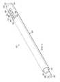
- FIG. 2illustrates a side view of an apparatus for applying reduced pressure to a subcutaneous tissue site according to an illustrative embodiment
- FIG. 3illustrates a perspective view of a distal portion of the apparatus of FIG. 2 with a portion of the apparatus shown in hidden lines;
- FIG. 4illustrates a perspective view of the apparatus of FIG. 2 ;
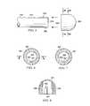
- FIG. 5illustrates a side view of a manifold and end cap according to an illustrative embodiment
- FIG. 6illustrates a cross-sectional front view of the end cap of FIG. 5 taken at 6 - 6 ;
- FIG. 7illustrates a cross-sectional front view of the end cap of FIG. 5 taken at 7 - 7 ;
- FIG. 8illustrates a cross-sectional view of a portion of the end cap of FIG. 6 taken at 8 - 8 ;
- FIG. 9illustrates a schematic of a reduced-pressure treatment system for applying reduced pressure to a tissue site in an abdominal cavity.
- reduced pressuregenerally refers to a pressure less than the ambient pressure at a tissue site that is being subjected to treatment. In most cases, this reduced pressure will be less than the atmospheric pressure at which the patient is located. Alternatively, the reduced pressure may be less than a hydrostatic pressure associated with tissue at the tissue site. Although the terms “vacuum” and “negative pressure” may be used to describe the pressure applied to the tissue site, the actual pressure reduction applied to the tissue site may be significantly less than the pressure reduction normally associated with a complete vacuum. Reduced pressure may initially generate fluid flow in the area of the tissue site. As the hydrostatic pressure around the tissue site approaches the desired reduced pressure, the flow may subside, and the reduced pressure is then maintained. Unless otherwise indicated, values of pressure stated herein are gauge pressures. Similarly, references to increases in reduced pressure typically refer to a decrease in absolute pressure, while decreases in reduced pressure typically refer to an increase in absolute pressure.
- a reduced-pressure treatment system 100which applies reduced pressure to a tissue site 103 , is shown according to an illustrative embodiment.
- the tissue site 103is a bone tissue site.
- the tissue site 103is a fracture on bone 106 , which in the example illustrated is a femur.
- reduced pressure at tissue site 103provides a number of benefits.
- reduced-pressure treatmentcan increase the rate of healing associated with a fracture, a non-union, a void, or other bone defects.
- Reduced-pressure treatmentmay also be used to improve recovery from osteomyelitis.
- the treatmentmay further be used to increase localized bone densities in patients suffering from osteoporosis.
- reduced-pressure treatmentmay be used to speed and improve osseointegration of orthopedic implants, such as hip implants, knee implants, and fixation devices.
- tissue site 103is bone tissue
- tissue siteas used herein may refer to a wound or defect located on or within any tissue, including but not limited to, bone tissue, adipose tissue, muscle tissue, neural tissue, dermal tissue, vascular tissue, connective tissue, cartilage, tendons, or ligaments.
- tissue sitemay further refer to areas of any tissue that are not necessarily wounded or defective, but are instead areas in which it is desired to add or promote the growth of additional tissue. For example, reduced pressure tissue treatment may be used in certain tissue areas to grow additional tissue that may be harvested and transplanted to another tissue location.
- a reduced pressure treatment system 100includes a reduced pressure source 109 and a manifold 112 that is positioned at the tissue site 103 .
- the reduced-pressure source 109provides reduced pressure to tissue site 103 through the manifold 112 .
- the manifold 112may include a passageway (not illustrated in FIG. 1 ) for administering reduced pressure and removing or supplying fluids to the tissue site 103 .
- the passagewaymay extend from a distal end 113 of the manifold 112 to a proximal end 114 .
- the manifold 112receives the reduced pressure from the reduced-pressure source 109 through a delivery conduit 115 , which is in fluid communication with the manifold 112 and delivers reduced pressure to the manifold 112 during treatment.
- the manifold 112may include at least one aperture, such as apertures 118 , and may deliver reduced pressure to the tissue site 103 via the apertures 118 .
- the manifold 112may be inserted into a sleeve 121 to provide reduced pressure treatment to the tissue site 103 .
- the sleeve 121which may be a lumen member, may extend from the tissue site 103 , through the patient's skin, and to a location external to the patient 124 .
- the proximal end 127 of the sleeve 121which has an opening 130 into which the manifold 112 may be inserted, may protrude from the patient 124 when the sleeve 121 is placed at the tissue site 103 .
- the manifold 112has a longitudinal length L 1
- the sleevehas a longitudinal length L 2
- a distance from the tissue site to a location external to the patientis L 3 .
- the proximal end 127 of the sleeve 121may be subcutaneously disposed in the patient 124 , i.e., L 2 ⁇ L 3 .
- the sleeve 121may be disposed at the tissue site 103 of a patient 124 in a variety of different spatial orientations, including the flexed orientation shown in FIG. 1 .
- the sleeve 121may be releasably secured to a patient 124 to hold the sleeve 121 in a fixed position with respect to the tissue site 103 or may be unsecured.
- the sleeve 121may be sutured into place or adhered using a medical epoxy, medical tape, or other means.
- the proximal end 127may include a flange (not shown) to prevent the proximal end 127 from entering the patient 124 .
- the flangemight be put in a position abutting an external portion of the patient 124 and adhered using epoxy, medical tape, sutures, etc.
- the sleeve 121is capable of slidably receiving the manifold 112 .
- the manifold 112may be inserted into the opening 130 and moved toward the distal end 133 of the sleeve 121 .
- the manifold 112may be placed adjacent an opening 136 in sleeve 121 .
- the opening 136may be located at a distal portion 139 of the sleeve 121 , may run the length of the sleeve 121 , or may take any shape or size.
- the manifold 112may include visual indicia (see by analogy 691 in FIG. 9 ) to help gauge the extent to which manifold 112 has been inserted into an interior portion of the sleeve 121 .
- An exterior portion of the manifold 112 or the interior portion of the sleeve 121 or bothmay include ribs to provide tactile feedback to the healthcare provider regarding the relative position of the sleeve 121 and the manifold 111 .
- the manifold 112is capable of delivering reduced pressure from the reduced-pressure source 109 to the tissue site 103 via the opening 136 in the sleeve 121 .
- the manifold 112may include a longitudinal ridge member (not shown) that is positioned along the length (or a portion of the length) of the manifold 112 and that mates with a longitudinal groove (not shown) on the interior portion of the sleeve 121 .
- the groovemay be on the manifold 112 and the ridge member on the sleeve 121 . This approach to securing the manifold 112 and sleeve 121 may further help assure that the manifold 112 assumes a proper position with respect to opening 136 and ultimately tissue site 103 .
- the manifold 112may be both insertable and removable from the sleeve 121 while the sleeve 121 remains at the tissue site 103 .
- a pneumatic sealmay be formed about the manifold 112 and sleeve 121 proximate an opening 119 in the patient 124 , e.g., an opening in the patient's skin.
- the pneumatic sealmay be formed using a drape material, medical tape, a hydrocolloid, or other sealing members.
- the manifold 112may be moved out of the sleeve 121 at any time. By allowing the manifold 112 to be inserted and removed from the sleeve 121 while the sleeve remains at the tissue site 103 , the system 100 facilitates effective reduced-pressure treatment of the tissue site 103 . For example, in the event that the manifold 112 becomes clogged, such as by fibrin, tissue, or any other bodily substance, the manifold 112 may be removed from the sleeve 121 and either cleaned or replaced with another manifold that can be inserted into the sleeve 121 .
- the manifold 112may be removed or re-inserted for any reason, such as to visually monitor the integrity of the manifold 112 or to facilitate the movement of the patient 124 by disconnecting the patient 124 from the reduced-pressure source 109 . Further, the insertion and removal of the manifold 112 may be repeated any number of times while minimizing the disruption of or damage to tissue in and around the tissue site 103 or at the skin.
- clogging of the manifold 112may be reduced or prevented by delivering a purging fluid to the manifold 112 .
- a fluid source 142may supply a purging fluid.
- the delivery conduit 115may deliver the fluid to the manifold 112 .
- the fluidmay be a liquid or a gas, such as air, and may purge any blockages in the manifold 112 .
- These purged substanceswhich may include fibrin, tissue, or any other bodily substance, are drawn out of the manifold 112 and toward the reduced-pressure source 109 using reduced pressure from the reduced-pressure source 109 .
- These substancesmay be received by a container 145 .
- the fluid source 142may also supply antibacterial agents, antiviral agents, cell-growth promotion agents, irrigation fluids, or other chemically active agents to the tissue site 103 .
- a method for applying reduced pressure to the tissue site 103includes inserting the sleeve 121 at the tissue site 103 such that the opening 136 on the sleeve 121 is adjacent the tissue site 103 .
- the methodmay also include inserting the manifold 112 , which includes apertures 118 , into the sleeve 121 . Reduced pressure is supplied to the tissue site 103 via the apertures 118 and the opening 136 .
- the methodmay further include removing the manifold 112 from the sleeve 121 .
- the sleeve 121may remain at the tissue site 103 , and the manifold 112 , or any other manifold, may be inserted or re-inserted into the sleeve 121 .
- the sleeve 121may also be removed from the tissue site 103 at any time, with or without the manifold 112 being positioned in the sleeve 121 .
- a method of manufacturing an apparatus for applying reduced pressure to the tissue site 103includes forming the sleeve 121 .
- the methodmay also include forming the manifold 112 .
- FIGS. 2-4an apparatus 201 for applying reduced pressure to a subcutaneous tissue site is shown in accordance with an illustrative embodiment.
- FIGS. 2-4show a manifold 212 and a sleeve 221 , which are similar to the manifold 112 and the sleeve 121 in FIG. 1 , respectively.
- the sleeve 221 and the manifold 212may have the same lateral cross-sectional shape.
- the sleeve 221 and the manifold 212have a circular lateral cross-section.
- the sleeve 221 or the manifold 212may have other lateral cross-sectional shapes, such as an ellipse, a polygon, an irregular shape, or a customized shape.
- the width 248 of the sleeve 221is preferably larger than the width 251 of the manifold 212 .
- the width 251 of the manifold 212is not required to be constant along the entire length of the manifold 219 .
- the width 251 of the manifold 212may instead be varied along its length relative to the width 248 of the sleeve 221 to increase or decrease the amount of space between the manifold 212 and the sleeve 221 .
- the sleeve 221 or the manifold 212may be made from a variety of biocompatible materials, including silicone.
- the sleeve 221may be flexible such that the sleeve 221 is bendable when inserted or disposed subcutaneously.
- the sleeve 221is composed of a more flexible material than the manifold 212 .
- the rigidity of the manifold 212may help to prevent the collapse of the manifold 212 when exposed to reduced pressure.
- the opening 236 of the sleeve 221may be located on a wall 257 , or side wall, of the sleeve 221 .
- the opening 236is positioned at or near the most distal portion 233 of sleeve 221 and expands along a length of the sleeve 221 .
- the opening 236is capable of transferring reduced pressure from the manifold 212 to a tissue site.
- the opening 236may extend along substantially the entire length 260 of the sleeve 221 .
- the opening 236is shown to have a substantially rectangular shape. However, the opening 236 may have any shape, including a circular, elliptical, polygonal, irregular, or customized shape. In the example in which the opening 236 has a customized shape, the opening 236 may be created based on the particular implementation or tissue site being treated by the apparatus 201 .
- sleeve 221may have two or more openings 236 .
- the two or more openings 236may face the same or different directions.
- two openings 236may be located on opposite sides of the wall 257 .
- the two openings 236may be located on the same side of the wall 257 , and may be aligned along the length 260 of the sleeve 221 .
- the size, shape, and number of openings 236may depend on the particular tissue site and type of treatment being implemented.
- Manifold 212includes a plurality of apertures 218 that partially or fully surround the manifold 212 .
- the apertures 218may be located around the circumference of the manifold 212 .
- each of the apertures 218may be disposed to substantially face toward the opening 236 when the manifold 212 is inserted in the sleeve 221 .
- the manifold 212may also include a flange 263 , which may partially or fully surround the manifold 212 .
- An outer edge 266 of the flange 263may at least partially abut an inner surface 269 of the sleeve 221 when the manifold 212 is inserted in the sleeve 221 .
- the outer edge 266 of the flange 263may be slidable along the inner surface 269 of the sleeve 221 when the manifold 212 is inserted into the sleeve in the direction of arrow 272 or removed in the direction of arrow 275 .
- the flange 263may disposed anywhere along the manifold 212 , including the end 278 of the manifold 212 . Any number of flanges 263 , such as two or more flanges 263 may be included.
- the flange 263is capable of moving a substance, such as a bodily substance or fluid, toward the proximal end 227 of the sleeve 221 when the manifold 212 is removed from the sleeve 221 as suggested by arrow 275 in FIG. 2 .
- a substancesuch as a bodily substance or fluid
- the removal of the manifold 212helps to clear the sleeve 221 , including the distal end 239 of the sleeve 221 , of debris, such as exudate, tissue, or any other substance.
- the width 281 , or outer diameter, of the flange 263may be larger than the width 283 of the opening 236 .
- the flange 263may help to prevent the manifold 212 from exiting the sleeve 221 through the opening 236 , especially when the manifold 212 is being inserted into the sleeve 221 .
- the interior of the sleeve 221may including a blocking member designed to engage flange 263 and stop further insertion of manifold 212 into sleeve 221 .
- the manifold 212may include a surface feature on a proximal portion that prevents further advancement of the manifold 212 into sleeve 221 .
- the flange 263includes at least one hole, such as holes 285 .
- the holes 285allow fluid communication between the space 287 on the distal side of the flange 263 and the space 289 on the proximal side of the flange 263 .
- the flange 263may include any number of holes 285 , and the holes 285 may have any shape. In one embodiment, the flange 263 has no holes 285 .
- the holes 285may have one-way valves in the holes 285 that allow fluid to be pulled out of the sleeve 221 when the manifold 212 is removed, but avoid pushing air or other fluids when the manifold 212 is moved into the sleeve 221 (i.e., the valves allow fluid flow through the valves in the direction of arrow 275 , but prevent flow in the direction of arrow 272 ).
- the flange 263is shown in FIG. 3 as being positioned along the length of opening 236 when the manifold 212 is fully inserted within the sleeve 221 , the flange 263 could instead be located distal to the opening 236 when the manifold 212 is fully inserted. In this particular embodiment, the positioning of the flange 263 distal to the opening 236 may allow the flange 263 to better remove all bodily debris and substances (when the manifold is removed) that enter the sleeve 221 through the opening 236 .
- the sleeve 221includes an end cap 291 that is coupled to a distal end 292 of the sleeve 221 .
- the term “coupled”includes coupling via a separate object, and also includes direct coupling. In the case of direct coupling, the two coupled objects touch each other in some way.
- the term “coupled”also encompasses two or more components that are continuous with one another by virtue of each of the components being formed from the same piece of material.
- the term “coupled”includes chemical coupling, such as via a chemical bond.
- the term “coupled”may also include mechanical, thermal, or electrical coupling. “Coupled” may also mean fixedly coupled or removably coupled.
- the end cap 291may prevent fluid and reduced pressure from entering or exiting the sleeve 221 at the distal end 292 of the sleeve 221 .
- the end cap 291may have any shape, including a rounded or dome shape. In the example in which the end cap 291 has a rounded or dome shape, the shape of the end cap 291 better facilitates the subcutaneous insertion of the sleeve 221 .
- the space 293 inside the end cap 291may be either hollow or solid. In another embodiment, the sleeve 221 does not include the end cap 291 .
- a delivery conduit 215which is functionally analogous to the delivery conduit 115 in FIG. 1 , may deliver reduced pressure or fluid to the manifold 212 .
- the delivery conduit 215may include two or more lumens, such as lumens 293 and 294 .
- the lumen 293delivers reduced pressure to the manifold 212
- the lumen 294delivers a fluid to the manifold 212 .
- the delivery conduit 215is fluidly coupled to the manifold 212 .
- a manifold 512which is similar to the manifold 112 in FIG. 1
- an end cap 591which is similar to the end cap 291 in FIGS. 2-4
- the end cap 591includes a securing wall 595 on a sleeve-facing side 596 of the end cap 591 .
- the securing wall 595receives the distal end 578 of the manifold 512 such that the securing wall 595 at least partially surrounds the distal end 578 of the manifold 512 and may form an interference fit.
- the distal end 578 of the manifoldmay receive and surround the securing wall 595 and may form an interference fit.
- the securing wall 595may stabilize, secure, or prevent relative movement, e.g., lateral or longitudinal movement, of the manifold 512 and sleeve 521 when the manifold 512 is inserted into the sleeve 521 .
- the space 502 around the securing wall 595may be hollow or solid.
- the end cap 591may be dome-shaped as shown or may be cylindrical, or may take any other shape.
- the securing wall 595may include at least one groove, such as groove 597
- the manifold 512may include at least one projection, such as projection 598 , at or near the distal end 578 of the manifold 512 .
- the projection 598radially extends from the manifold 512 .
- the groove 597slidably receives the projection 598 .
- the manifoldWhen the groove 597 slidably receives the projection 598 , the manifold is oriented such that the apertures 518 may face the opening (not shown) in the sleeve. By moving the projection 598 into a locking portion 599 of the groove 597 , the movement of the manifold 512 out of the sleeve may be hindered or prevented. In another embodiment, the groove 597 does not include the locking portion 599 .
- the illustrative embodiments of sleeves and manifoldsmay be used to provide reduced pressure treatment to one or more tissue sites and at tissue sites located at various locations within a patient.
- the system 100 in FIG. 1is shown applied to a tissue site 103 that is a bone.
- a reduced-pressure treatment system 600is capable of providing reduced pressure to an abdominal tissue site 603 .
- the system 600is analogous to system 100 , and similar parts to those in FIG. 1 have been shown with reference numerals indexed by 500 .
- the tissue site 603is within an abdominal cavity and in particular within a paracolic gutter 607 of a patient 624 .
- a manifold 612is inserted into a sleeve 621 .
- the sleeve 621has a distal end 625 and a proximal end 627 .
- the proximal end 627 of the sleeve 621has an opening 630 into which the manifold 612 may be inserted.
- system 600is shown applied to one paracolic gutter 607 , but may be applied bilaterally to provide reduced pressure treatment to a paracolic gutter 611 on the other side of the patient 624 .
- the sleeve 621is inserted through an opening in the patient's abdomen and positioned in the paracolic gutter 607 .
- the manifold 612is inserted into the sleeve 621 .
- the manifold 612is positioned to have apertures 618 proximate opening 636 and proximate tissue site 603 .
- the proximal end 690 of the manifold 612is coupled to a delivery conduit 615 .
- the delivery conduit 615provides reduced pressure from a reduced pressure source 609 to remove fluids (e.g., ascites or exudates) from the tissue site 603 , which are then are collected within a container 645 .
- the delivery conduit 615may also provide a fluid from a fluid source 642 .
- the proximal end 690 of the manifold 612may include visual indicia 691 to help the healthcare provider gauge the extent to which manifold 612 has been inserted into the sleeve 621 .
- the proximal end 690may also have a flange or other device to avoid over insertion of the manifold 612 into the sleeve 621 .
- the system 600may be used to provide reduced pressure treatment at the wound site 603 or to only remove fluids, e.g., ascites, from the abdominal cavity. Numerous other tissue sites are also possible.
Landscapes
- Health & Medical Sciences (AREA)
- Heart & Thoracic Surgery (AREA)
- Animal Behavior & Ethology (AREA)
- General Health & Medical Sciences (AREA)
- Anesthesiology (AREA)
- Biomedical Technology (AREA)
- Hematology (AREA)
- Life Sciences & Earth Sciences (AREA)
- Vascular Medicine (AREA)
- Engineering & Computer Science (AREA)
- Public Health (AREA)
- Veterinary Medicine (AREA)
- Media Introduction/Drainage Providing Device (AREA)
- Surgical Instruments (AREA)
- External Artificial Organs (AREA)
- Infusion, Injection, And Reservoir Apparatuses (AREA)
Abstract
Description
Claims (26)
Priority Applications (4)
| Application Number | Priority Date | Filing Date | Title |
|---|---|---|---|
| US12/645,146US8795245B2 (en) | 2008-12-31 | 2009-12-22 | Sleeves, manifolds, systems, and methods for applying reduced pressure to a subcutaneous tissue site |
| TW098146569ATW201029694A (en) | 2008-12-31 | 2009-12-31 | Sleeves, manifolds, systems, and methods for applying reduced pressure to a subcutaneous tissue site |
| US14/312,343US10207034B2 (en) | 2008-12-31 | 2014-06-23 | Sleeves, manifolds, systems, and methods for applying reduced pressure to a subcutaneous tissue site |
| US16/241,742US20190167868A1 (en) | 2008-12-31 | 2019-01-07 | Sleeves, Manifolds, Systems, And Methods For Applying Reduced Pressure To A Subcutaneous Tissue Site |
Applications Claiming Priority (2)
| Application Number | Priority Date | Filing Date | Title |
|---|---|---|---|
| US14171608P | 2008-12-31 | 2008-12-31 | |
| US12/645,146US8795245B2 (en) | 2008-12-31 | 2009-12-22 | Sleeves, manifolds, systems, and methods for applying reduced pressure to a subcutaneous tissue site |
Related Child Applications (1)
| Application Number | Title | Priority Date | Filing Date |
|---|---|---|---|
| US14/312,343DivisionUS10207034B2 (en) | 2008-12-31 | 2014-06-23 | Sleeves, manifolds, systems, and methods for applying reduced pressure to a subcutaneous tissue site |
Publications (2)
| Publication Number | Publication Date |
|---|---|
| US20100168692A1 US20100168692A1 (en) | 2010-07-01 |
| US8795245B2true US8795245B2 (en) | 2014-08-05 |
Family
ID=42285822
Family Applications (3)
| Application Number | Title | Priority Date | Filing Date |
|---|---|---|---|
| US12/645,146Active2032-05-02US8795245B2 (en) | 2008-12-31 | 2009-12-22 | Sleeves, manifolds, systems, and methods for applying reduced pressure to a subcutaneous tissue site |
| US14/312,343Active2029-12-26US10207034B2 (en) | 2008-12-31 | 2014-06-23 | Sleeves, manifolds, systems, and methods for applying reduced pressure to a subcutaneous tissue site |
| US16/241,742AbandonedUS20190167868A1 (en) | 2008-12-31 | 2019-01-07 | Sleeves, Manifolds, Systems, And Methods For Applying Reduced Pressure To A Subcutaneous Tissue Site |
Family Applications After (2)
| Application Number | Title | Priority Date | Filing Date |
|---|---|---|---|
| US14/312,343Active2029-12-26US10207034B2 (en) | 2008-12-31 | 2014-06-23 | Sleeves, manifolds, systems, and methods for applying reduced pressure to a subcutaneous tissue site |
| US16/241,742AbandonedUS20190167868A1 (en) | 2008-12-31 | 2019-01-07 | Sleeves, Manifolds, Systems, And Methods For Applying Reduced Pressure To A Subcutaneous Tissue Site |
Country Status (12)
| Country | Link |
|---|---|
| US (3) | US8795245B2 (en) |
| EP (2) | EP3590554B1 (en) |
| JP (2) | JP5654483B2 (en) |
| KR (1) | KR20110119676A (en) |
| CN (1) | CN102264406B (en) |
| AU (1) | AU2009333031B2 (en) |
| CA (1) | CA2745192C (en) |
| MX (1) | MX2011006993A (en) |
| RU (1) | RU2011122548A (en) |
| SG (1) | SG172023A1 (en) |
| TW (1) | TW201029694A (en) |
| WO (1) | WO2010078166A2 (en) |
Cited By (1)
| Publication number | Priority date | Publication date | Assignee | Title |
|---|---|---|---|---|
| US9474883B2 (en) | 2012-12-06 | 2016-10-25 | Ic Surgical, Inc. | Adaptable wound drainage system |
Families Citing this family (55)
| Publication number | Priority date | Publication date | Assignee | Title |
|---|---|---|---|---|
| US11298453B2 (en) | 2003-10-28 | 2022-04-12 | Smith & Nephew Plc | Apparatus and method for wound cleansing with actives |
| GB0508531D0 (en) | 2005-04-27 | 2005-06-01 | Smith & Nephew | Sai with ultrasound |
| US8048089B2 (en) | 2005-12-30 | 2011-11-01 | Edge Systems Corporation | Apparatus and methods for treating the skin |
| US9566088B2 (en) | 2006-03-29 | 2017-02-14 | Edge Systems Llc | Devices, systems and methods for treating the skin |
| GB0723872D0 (en) | 2007-12-06 | 2008-01-16 | Smith & Nephew | Apparatus for topical negative pressure therapy |
| KR20100129269A (en) | 2008-01-04 | 2010-12-08 | 엣지 시스템즈 코포레이션 | Skin treatment device and method |
| US9056193B2 (en) | 2008-01-29 | 2015-06-16 | Edge Systems Llc | Apparatus and method for treating the skin |
| US8298200B2 (en) | 2009-06-01 | 2012-10-30 | Tyco Healthcare Group Lp | System for providing continual drainage in negative pressure wound therapy |
| ES2658263T3 (en) | 2008-08-08 | 2018-03-09 | Smith & Nephew, Inc. | Continuous fiber wound dressing |
| MX2011006993A (en) | 2008-12-31 | 2011-08-04 | Kci Licensing Inc | Sleeves, manifolds, systems, and methods for applying reduced pressure to a subcutaneous tissue site. |
| US8864728B2 (en)* | 2008-12-31 | 2014-10-21 | Kci Licensing, Inc. | Multi-conduit manifolds, systems, and methods for applying reduced pressure to a subcutaneous tissue site |
| US8162907B2 (en) | 2009-01-20 | 2012-04-24 | Tyco Healthcare Group Lp | Method and apparatus for bridging from a dressing in negative pressure wound therapy |
| US20100324516A1 (en) | 2009-06-18 | 2010-12-23 | Tyco Healthcare Group Lp | Apparatus for Vacuum Bridging and/or Exudate Collection |
| AU2010341491B2 (en) | 2009-12-22 | 2015-05-14 | Smith & Nephew, Inc. | Apparatuses and methods for negative pressure wound therapy |
| USRE48117E1 (en) | 2010-05-07 | 2020-07-28 | Smith & Nephew, Inc. | Apparatuses and methods for negative pressure wound therapy |
| RU2016111981A (en) | 2010-12-22 | 2018-11-27 | Смит Энд Нефью, Инк. | DEVICE AND METHOD FOR TREATING RAS WITH NEGATIVE PRESSURE |
| JP6250571B2 (en) | 2012-03-12 | 2017-12-20 | スミス アンド ネフュー ピーエルシーSmith & Nephew Public Limited Company | Pressure reducing apparatus and method |
| JP6400570B2 (en) | 2012-05-23 | 2018-10-10 | スミス アンド ネフュー ピーエルシーSmith & Nephew Public Limited Company | Apparatus and method for local negative pressure closure therapy |
| WO2014020440A1 (en) | 2012-08-01 | 2014-02-06 | Smith & Nephew Plc | Wound dressing |
| CN108186200B (en) | 2012-08-01 | 2021-08-10 | 史密夫及内修公开有限公司 | Wound dressing |
| DE102012025125A1 (en) | 2012-12-21 | 2014-06-26 | Paul Hartmann Ag | Absorbent body for the therapeutic treatment of a wound by means of negative pressure |
| EP3437575B1 (en) | 2013-03-15 | 2021-04-21 | Edge Systems LLC | Devices and systems for treating the skin |
| US10010658B2 (en) | 2013-05-10 | 2018-07-03 | Smith & Nephew Plc | Fluidic connector for irrigation and aspiration of wounds |
| EP4324414A3 (en) | 2014-12-23 | 2024-05-01 | HydraFacial LLC | Devices and methods for treating the skin using a rollerball or a wicking member |
| US10179229B2 (en) | 2014-12-23 | 2019-01-15 | Edge Systems Llc | Devices and methods for treating the skin using a porous member |
| DK3288508T3 (en) | 2015-04-27 | 2020-03-09 | Smith & Nephew | REDUCED PRESSURE DEVICES |
| US10076594B2 (en) | 2015-05-18 | 2018-09-18 | Smith & Nephew Plc | Fluidic connector for negative pressure wound therapy |
| EP3426206B1 (en) | 2016-03-07 | 2023-05-10 | Smith & Nephew plc | Wound treatment apparatuses and methods with negative pressure source integrated into wound dressing |
| CA3022184A1 (en) | 2016-04-26 | 2017-11-02 | Smith & Nephew Plc | Wound dressings and methods of use with integrated negative pressure source having a fluid ingress inhibition component |
| WO2017191158A1 (en) | 2016-05-03 | 2017-11-09 | Smith & Nephew Plc | Systems and methods for driving negative pressure sources in negative pressure therapy systems |
| CA3038206A1 (en) | 2016-05-03 | 2017-11-09 | Smith & Nephew Plc | Optimizing power transfer to negative pressure sources in negative pressure therapy systems |
| US11096831B2 (en) | 2016-05-03 | 2021-08-24 | Smith & Nephew Plc | Negative pressure wound therapy device activation and control |
| WO2018037075A1 (en) | 2016-08-25 | 2018-03-01 | Smith & Nephew Plc | Absorbent negative pressure wound therapy dressing |
| EP3519001B1 (en) | 2016-09-30 | 2025-05-21 | Smith & Nephew plc | Negative pressure wound treatment apparatuses and methods with integrated electronics |
| EP3551244A1 (en) | 2016-12-12 | 2019-10-16 | Smith & Nephew PLC | Pressure wound therapy status indication via external device |
| EP3592312B1 (en) | 2017-03-08 | 2024-01-10 | Smith & Nephew plc | Negative pressure wound therapy device control in presence of fault condition |
| JP7121050B2 (en) | 2017-05-09 | 2022-08-17 | スミス アンド ネフュー ピーエルシー | Redundant control of negative pressure wound therapy systems |
| GB201718070D0 (en) | 2017-11-01 | 2017-12-13 | Smith & Nephew | Negative pressure wound treatment apparatuses and methods with integrated electronics |
| CA3074780A1 (en) | 2017-09-13 | 2019-03-21 | Smith & Nephew Plc | Negative pressure wound treatment apparatuses and methods with integrated electronics |
| US11497653B2 (en) | 2017-11-01 | 2022-11-15 | Smith & Nephew Plc | Negative pressure wound treatment apparatuses and methods with integrated electronics |
| GB201718014D0 (en) | 2017-11-01 | 2017-12-13 | Smith & Nephew | Dressing for negative pressure wound therapy with filter |
| GB201718072D0 (en) | 2017-11-01 | 2017-12-13 | Smith & Nephew | Negative pressure wound treatment apparatuses and methods with integrated electronics |
| GB201718054D0 (en) | 2017-11-01 | 2017-12-13 | Smith & Nephew | Sterilization of integrated negative pressure wound treatment apparatuses and sterilization methods |
| GB201811449D0 (en) | 2018-07-12 | 2018-08-29 | Smith & Nephew | Apparatuses and methods for negative pressure wound therapy |
| USD898925S1 (en) | 2018-09-13 | 2020-10-13 | Smith & Nephew Plc | Medical dressing |
| EP3829690B1 (en) | 2018-10-02 | 2022-11-30 | Boston Scientific Scimed, Inc. | Devices for fluidization and delivering a powdered agent |
| US12042175B2 (en)* | 2019-02-13 | 2024-07-23 | Stryker European Operations Limited | Bone material harvesting device |
| GB201903774D0 (en) | 2019-03-20 | 2019-05-01 | Smith & Nephew | Negative pressure wound treatment apparatuses and methods with integrated electronics |
| GB201907716D0 (en) | 2019-05-31 | 2019-07-17 | Smith & Nephew | Systems and methods for extending operational time of negative pressure wound treatment apparatuses |
| US11291474B2 (en) | 2020-01-06 | 2022-04-05 | Ed F. Nicolas | Skin treatment tool applicator tip |
| GB202000574D0 (en) | 2020-01-15 | 2020-02-26 | Smith & Nephew | Fluidic connectors for negative pressure wound therapy |
| USD1016615S1 (en) | 2021-09-10 | 2024-03-05 | Hydrafacial Llc | Container for a skin treatment device |
| USD1065551S1 (en) | 2021-09-10 | 2025-03-04 | Hydrafacial Llc | Skin treatment device |
| USD1042807S1 (en) | 2021-10-11 | 2024-09-17 | Hydrafacial Llc | Skin treatment tip |
| USD1084369S1 (en) | 2023-02-10 | 2025-07-15 | Hydrafacial Llc | Skin treatment tip |
Citations (128)
| Publication number | Priority date | Publication date | Assignee | Title |
|---|---|---|---|---|
| US1355846A (en) | 1920-02-06 | 1920-10-19 | David A Rannells | Medical appliance |
| US2547758A (en) | 1949-01-05 | 1951-04-03 | Wilmer B Keeling | Instrument for treating the male urethra |
| US2632443A (en) | 1949-04-18 | 1953-03-24 | Eleanor P Lesher | Surgical dressing |
| GB692578A (en) | 1949-09-13 | 1953-06-10 | Minnesota Mining & Mfg | Improvements in or relating to drape sheets for surgical use |
| US2682873A (en) | 1952-07-30 | 1954-07-06 | Johnson & Johnson | General purpose protective dressing |
| US2910763A (en) | 1955-08-17 | 1959-11-03 | Du Pont | Felt-like products |
| US2969057A (en) | 1957-11-04 | 1961-01-24 | Brady Co W H | Nematodic swab |
| US3066672A (en) | 1960-09-27 | 1962-12-04 | Jr William H Crosby | Method and apparatus for serial sampling of intestinal juice |
| US3367332A (en) | 1965-08-27 | 1968-02-06 | Gen Electric | Product and process for establishing a sterile area of skin |
| US3520300A (en) | 1967-03-15 | 1970-07-14 | Amp Inc | Surgical sponge and suction device |
| US3568675A (en) | 1968-08-30 | 1971-03-09 | Clyde B Harvey | Fistula and penetrating wound dressing |
| US3648692A (en) | 1970-12-07 | 1972-03-14 | Parke Davis & Co | Medical-surgical dressing for burns and the like |
| US3682180A (en) | 1970-06-08 | 1972-08-08 | Coilform Co Inc | Drain clip for surgical drain |
| US3826254A (en) | 1973-02-26 | 1974-07-30 | Verco Ind | Needle or catheter retaining appliance |
| DE2640413A1 (en) | 1976-09-08 | 1978-03-09 | Wolf Gmbh Richard | CATHETER MONITORING DEVICE |
| US4080970A (en) | 1976-11-17 | 1978-03-28 | Miller Thomas J | Post-operative combination dressing and internal drain tube with external shield and tube connector |
| US4096853A (en) | 1975-06-21 | 1978-06-27 | Hoechst Aktiengesellschaft | Device for the introduction of contrast medium into an anus praeter |
| US4139004A (en) | 1977-02-17 | 1979-02-13 | Gonzalez Jr Harry | Bandage apparatus for treating burns |
| US4165748A (en) | 1977-11-07 | 1979-08-28 | Johnson Melissa C | Catheter tube holder |
| US4184510A (en) | 1977-03-15 | 1980-01-22 | Fibra-Sonics, Inc. | Valued device for controlling vacuum in surgery |
| US4233969A (en) | 1976-11-11 | 1980-11-18 | Lock Peter M | Wound dressing materials |
| US4245630A (en) | 1976-10-08 | 1981-01-20 | T. J. Smith & Nephew, Ltd. | Tearable composite strip of materials |
| US4256109A (en) | 1978-07-10 | 1981-03-17 | Nichols Robert L | Shut off valve for medical suction apparatus |
| US4261363A (en) | 1979-11-09 | 1981-04-14 | C. R. Bard, Inc. | Retention clips for body fluid drains |
| US4275721A (en) | 1978-11-28 | 1981-06-30 | Landstingens Inkopscentral Lic, Ekonomisk Forening | Vein catheter bandage |
| US4284079A (en) | 1979-06-28 | 1981-08-18 | Adair Edwin Lloyd | Method for applying a male incontinence device |
| US4297995A (en) | 1980-06-03 | 1981-11-03 | Key Pharmaceuticals, Inc. | Bandage containing attachment post |
| US4333468A (en) | 1980-08-18 | 1982-06-08 | Geist Robert W | Mesentery tube holder apparatus |
| US4373519A (en) | 1981-06-26 | 1983-02-15 | Minnesota Mining And Manufacturing Company | Composite wound dressing |
| US4382441A (en) | 1978-12-06 | 1983-05-10 | Svedman Paul | Device for treating tissues, for example skin |
| US4392853A (en) | 1981-03-16 | 1983-07-12 | Rudolph Muto | Sterile assembly for protecting and fastening an indwelling device |
| US4392858A (en) | 1981-07-16 | 1983-07-12 | Sherwood Medical Company | Wound drainage device |
| US4419097A (en) | 1981-07-31 | 1983-12-06 | Rexar Industries, Inc. | Attachment for catheter tube |
| EP0100148A1 (en) | 1982-07-06 | 1984-02-08 | Dow Corning Limited | Medical-surgical dressing and a process for the production thereof |
| US4465485A (en) | 1981-03-06 | 1984-08-14 | Becton, Dickinson And Company | Suction canister with unitary shut-off valve and filter features |
| EP0117632A2 (en) | 1983-01-27 | 1984-09-05 | Johnson & Johnson Products Inc. | Adhesive film dressing |
| US4475909A (en) | 1982-05-06 | 1984-10-09 | Eisenberg Melvin I | Male urinary device and method for applying the device |
| US4480638A (en) | 1980-03-11 | 1984-11-06 | Eduard Schmid | Cushion for holding an element of grafted skin |
| US4525166A (en) | 1981-11-21 | 1985-06-25 | Intermedicat Gmbh | Rolled flexible medical suction drainage device |
| US4525374A (en) | 1984-02-27 | 1985-06-25 | Manresa, Inc. | Treating hydrophobic filters to render them hydrophilic |
| US4540412A (en) | 1983-07-14 | 1985-09-10 | The Kendall Company | Device for moist heat therapy |
| US4543100A (en) | 1983-11-01 | 1985-09-24 | Brodsky Stuart A | Catheter and drain tube retainer |
| US4548202A (en) | 1983-06-20 | 1985-10-22 | Ethicon, Inc. | Mesh tissue fasteners |
| US4551139A (en) | 1982-02-08 | 1985-11-05 | Marion Laboratories, Inc. | Method and apparatus for burn wound treatment |
| EP0161865A2 (en) | 1984-05-03 | 1985-11-21 | Smith and Nephew Associated Companies p.l.c. | Adhesive wound dressing |
| US4569348A (en) | 1980-02-22 | 1986-02-11 | Velcro Usa Inc. | Catheter tube holder strap |
| US4605399A (en) | 1984-12-04 | 1986-08-12 | Complex, Inc. | Transdermal infusion device |
| US4608041A (en) | 1981-10-14 | 1986-08-26 | Frese Nielsen | Device for treatment of wounds in body tissue of patients by exposure to jets of gas |
| US4640688A (en) | 1985-08-23 | 1987-02-03 | Mentor Corporation | Urine collection catheter |
| US4655754A (en) | 1984-11-09 | 1987-04-07 | Stryker Corporation | Vacuum wound drainage system and lipids baffle therefor |
| US4664662A (en) | 1984-08-02 | 1987-05-12 | Smith And Nephew Associated Companies Plc | Wound dressing |
| US4710165A (en) | 1985-09-16 | 1987-12-01 | Mcneil Charles B | Wearable, variable rate suction/collection device |
| US4733659A (en) | 1986-01-17 | 1988-03-29 | Seton Company | Foam bandage |
| GB2195255A (en) | 1986-09-30 | 1988-04-07 | Vacutec Uk Limited | Method and apparatus for vacuum treatment of an epidermal surface |
| US4743232A (en) | 1986-10-06 | 1988-05-10 | The Clinipad Corporation | Package assembly for plastic film bandage |
| GB2197789A (en) | 1986-11-28 | 1988-06-02 | Smiths Industries Plc | Anti-foaming disinfectants used in surgical suction apparatus |
| US4758220A (en) | 1985-09-26 | 1988-07-19 | Alcon Laboratories, Inc. | Surgical cassette proximity sensing and latching apparatus |
| US4787888A (en) | 1987-06-01 | 1988-11-29 | University Of Connecticut | Disposable piezoelectric polymer bandage for percutaneous delivery of drugs and method for such percutaneous delivery (a) |
| US4826494A (en) | 1984-11-09 | 1989-05-02 | Stryker Corporation | Vacuum wound drainage system |
| US4838883A (en) | 1986-03-07 | 1989-06-13 | Nissho Corporation | Urine-collecting device |
| US4840187A (en) | 1986-09-11 | 1989-06-20 | Bard Limited | Sheath applicator |
| US4863449A (en) | 1987-07-06 | 1989-09-05 | Hollister Incorporated | Adhesive-lined elastic condom cathether |
| US4872450A (en) | 1984-08-17 | 1989-10-10 | Austad Eric D | Wound dressing and method of forming same |
| US4878901A (en) | 1986-10-10 | 1989-11-07 | Sachse Hans Ernst | Condom catheter, a urethral catheter for the prevention of ascending infections |
| GB2220357A (en) | 1988-05-28 | 1990-01-10 | Smiths Industries Plc | Medico-surgical containers |
| US4897081A (en) | 1984-05-25 | 1990-01-30 | Thermedics Inc. | Percutaneous access device |
| US4906240A (en) | 1988-02-01 | 1990-03-06 | Matrix Medica, Inc. | Adhesive-faced porous absorbent sheet and method of making same |
| US4906233A (en) | 1986-05-29 | 1990-03-06 | Terumo Kabushiki Kaisha | Method of securing a catheter body to a human skin surface |
| US4919654A (en) | 1988-08-03 | 1990-04-24 | Kalt Medical Corporation | IV clamp with membrane |
| CA2005436A1 (en) | 1988-12-13 | 1990-06-13 | Glenda G. Kalt | Transparent tracheostomy tube dressing |
| US4941882A (en) | 1987-03-14 | 1990-07-17 | Smith And Nephew Associated Companies, P.L.C. | Adhesive dressing for retaining a cannula on the skin |
| US4953565A (en) | 1986-11-26 | 1990-09-04 | Shunro Tachibana | Endermic application kits for external medicines |
| US4969880A (en) | 1989-04-03 | 1990-11-13 | Zamierowski David S | Wound dressing and treatment method |
| US4985019A (en) | 1988-03-11 | 1991-01-15 | Michelson Gary K | X-ray marker |
| GB2235877A (en) | 1989-09-18 | 1991-03-20 | Antonio Talluri | Closed wound suction apparatus |
| US5037397A (en) | 1985-05-03 | 1991-08-06 | Medical Distributors, Inc. | Universal clamp |
| US5086170A (en) | 1989-01-16 | 1992-02-04 | Roussel Uclaf | Process for the preparation of azabicyclo compounds |
| US5092858A (en) | 1990-03-20 | 1992-03-03 | Becton, Dickinson And Company | Liquid gelling agent distributor device |
| US5100396A (en) | 1989-04-03 | 1992-03-31 | Zamierowski David S | Fluidic connection system and method |
| US5134994A (en) | 1990-02-12 | 1992-08-04 | Say Sam L | Field aspirator in a soft pack with externally mounted container |
| US5149331A (en) | 1991-05-03 | 1992-09-22 | Ariel Ferdman | Method and device for wound closure |
| US5167613A (en) | 1992-03-23 | 1992-12-01 | The Kendall Company | Composite vented wound dressing |
| US5176663A (en) | 1987-12-02 | 1993-01-05 | Pal Svedman | Dressing having pad with compressibility limiting elements |
| US5215522A (en) | 1984-07-23 | 1993-06-01 | Ballard Medical Products | Single use medical aspirating device and method |
| US5232453A (en) | 1989-07-14 | 1993-08-03 | E. R. Squibb & Sons, Inc. | Catheter holder |
| US5261893A (en) | 1989-04-03 | 1993-11-16 | Zamierowski David S | Fastening system and method |
| US5278100A (en) | 1991-11-08 | 1994-01-11 | Micron Technology, Inc. | Chemical vapor deposition technique for depositing titanium silicide on semiconductor wafers |
| US5279550A (en) | 1991-12-19 | 1994-01-18 | Gish Biomedical, Inc. | Orthopedic autotransfusion system |
| US5298015A (en) | 1989-07-11 | 1994-03-29 | Nippon Zeon Co., Ltd. | Wound dressing having a porous structure |
| US5342376A (en) | 1993-05-03 | 1994-08-30 | Dermagraphics, Inc. | Inserting device for a barbed tissue connector |
| US5344415A (en) | 1993-06-15 | 1994-09-06 | Deroyal Industries, Inc. | Sterile system for dressing vascular access site |
| DE4306478A1 (en) | 1993-03-02 | 1994-09-08 | Wolfgang Dr Wagner | Drainage device, in particular pleural drainage device, and drainage method |
| US5358494A (en) | 1989-07-11 | 1994-10-25 | Svedman Paul | Irrigation dressing |
| US5437651A (en) | 1993-09-01 | 1995-08-01 | Research Medical, Inc. | Medical suction apparatus |
| US5437622A (en) | 1992-04-29 | 1995-08-01 | Laboratoire Hydrex (Sa) | Transparent adhesive dressing with reinforced starter cuts |
| DE29504378U1 (en) | 1995-03-15 | 1995-09-14 | MTG Medizinisch, technische Gerätebau GmbH, 66299 Friedrichsthal | Electronically controlled low-vacuum pump for chest and wound drainage |
| US5527293A (en) | 1989-04-03 | 1996-06-18 | Kinetic Concepts, Inc. | Fastening system and method |
| US5549584A (en) | 1994-02-14 | 1996-08-27 | The Kendall Company | Apparatus for removing fluid from a wound |
| US5556375A (en) | 1994-06-16 | 1996-09-17 | Hercules Incorporated | Wound dressing having a fenestrated base layer |
| US5607388A (en) | 1994-06-16 | 1997-03-04 | Hercules Incorporated | Multi-purpose wound dressing |
| US5636643A (en) | 1991-11-14 | 1997-06-10 | Wake Forest University | Wound treatment employing reduced pressure |
| US5645081A (en) | 1991-11-14 | 1997-07-08 | Wake Forest University | Method of treating tissue damage and apparatus for same |
| GB2333965A (en) | 1997-09-12 | 1999-08-11 | Kci Medical Ltd | Surgical drape |
| US6071267A (en) | 1998-02-06 | 2000-06-06 | Kinetic Concepts, Inc. | Medical patient fluid management interface system and method |
| US6135116A (en) | 1997-07-28 | 2000-10-24 | Kci Licensing, Inc. | Therapeutic method for treating ulcers |
| US6241747B1 (en) | 1993-05-03 | 2001-06-05 | Quill Medical, Inc. | Barbed Bodily tissue connector |
| US6287316B1 (en) | 1999-03-26 | 2001-09-11 | Ethicon, Inc. | Knitted surgical mesh |
| US20020077661A1 (en) | 2000-12-20 | 2002-06-20 | Vahid Saadat | Multi-barbed device for retaining tissue in apposition and methods of use |
| US20020115951A1 (en) | 2001-02-22 | 2002-08-22 | Core Products International, Inc. | Ankle brace providing upper and lower ankle adjustment |
| US20020120185A1 (en) | 2000-05-26 | 2002-08-29 | Kci Licensing, Inc. | System for combined transcutaneous blood gas monitoring and vacuum assisted wound closure |
| US20020128632A1 (en)* | 1990-12-14 | 2002-09-12 | Cucin Robert L. | Power-assisted liposuction instrument with cauterizing cannula assembly |
| US20020143286A1 (en) | 2001-03-05 | 2002-10-03 | Kci Licensing, Inc. | Vacuum assisted wound treatment apparatus and infection identification system and method |
| US6488643B1 (en) | 1998-10-08 | 2002-12-03 | Kci Licensing, Inc. | Wound healing foot wrap |
| US6493568B1 (en) | 1994-07-19 | 2002-12-10 | Kci Licensing, Inc. | Patient interface system |
| AU755496B2 (en) | 1997-09-12 | 2002-12-12 | Kci Licensing, Inc. | Surgical drape and suction head for wound treatment |
| US20030105422A1 (en) | 2001-11-07 | 2003-06-05 | Bertrand Gonon | Liposuction apparatus with pressurized liquid spray and liposuction method using the apparatus |
| US20040093026A1 (en) | 2002-11-07 | 2004-05-13 | Rolf Weidenhagen | Endoscopic wound care treatment system and method |
| US7169151B1 (en) | 2003-04-10 | 2007-01-30 | Kci Licensing, Inc. | Bone regeneration device for long bones, and method of use |
| US20070060935A1 (en)* | 2005-07-11 | 2007-03-15 | Schwardt Jeffrey D | Apparatus and methods of tissue removal within a spine |
| US20070219471A1 (en) | 2006-03-14 | 2007-09-20 | Johnson Royce W | System for percutaneously administering reduced pressure treatment using balloon dissection |
| US20070219497A1 (en) | 2006-02-06 | 2007-09-20 | Johnson Royce W | System and method for purging a reduced pressure apparatus during the administration of reduced pressure treatment |
| US20070282309A1 (en) | 2006-06-02 | 2007-12-06 | Bengtson Bradley P | Assemblies, systems, and methods for vacuum assisted internal drainage during wound healing |
| US20070282310A1 (en) | 2006-06-02 | 2007-12-06 | Bengtson Bradley P | Assemblies, systems, and methods for vacuum assisted internal drainage during wound healing |
| US20080033324A1 (en) | 2006-03-14 | 2008-02-07 | Cornet Douglas A | System for administering reduced pressure treatment having a manifold with a primary flow passage and a blockage prevention member |
| JP4129536B2 (en) | 2000-02-24 | 2008-08-06 | ヴェネテック インターナショナル,インコーポレイテッド | Highly compatible catheter anchoring system |
| US20080275409A1 (en) | 2007-05-01 | 2008-11-06 | The Brigham And Women's Hospital, Inc. | Wound healing device |
| US20090028718A1 (en) | 2007-07-20 | 2009-01-29 | Peder Bay Enevoldsen | Wind turbine rotor blade and pitch regulated wind turbine |
| US20100168692A1 (en) | 2008-12-31 | 2010-07-01 | Barbara Anne Collins | Sleeves, manifolds, systems, and methods for applying reduced pressure to a subcutaneous tissue site |
Family Cites Families (29)
| Publication number | Priority date | Publication date | Assignee | Title |
|---|---|---|---|---|
| US7006A (en)* | 1850-01-08 | Chubh | ||
| US4266545A (en) | 1979-04-06 | 1981-05-12 | Moss James P | Portable suction device for collecting fluids from a closed wound |
| AU550575B2 (en) | 1981-08-07 | 1986-03-27 | Richard Christian Wright | Wound drainage device |
| JPS60106639U (en)* | 1983-12-27 | 1985-07-20 | テルモ株式会社 | catheter |
| US4941862A (en)* | 1985-02-22 | 1990-07-17 | Gkn Automotive Inc. | Quick disconnect constant velocity universal joint |
| EP0256060A1 (en) | 1986-01-31 | 1988-02-24 | OSMOND, Roger L. W. | Suction system for wound and gastro-intestinal drainage |
| US4721123A (en)* | 1986-10-23 | 1988-01-26 | Minntech Corporation | Catheter reprocessing system |
| GB8906100D0 (en) | 1989-03-16 | 1989-04-26 | Smith & Nephew | Laminates |
| JP2941918B2 (en) | 1990-09-19 | 1999-08-30 | テルモ株式会社 | Weighing device |
| MX9202604A (en)* | 1991-05-29 | 1994-05-31 | Origin Medsystems Inc | APPARATUS FOR MECHANICAL PROPERTY RETRACTION AND METHODS OF USE. |
| DE69505545T2 (en) | 1994-08-22 | 1999-03-11 | Kinetic Concepts Inc | WOUND DRAINAGE DEVICE |
| GB9523253D0 (en) | 1995-11-14 | 1996-01-17 | Mediscus Prod Ltd | Portable wound treatment apparatus |
| US5749826A (en)* | 1996-11-06 | 1998-05-12 | Faulkner; James W. | Urinary incontinence control device |
| US5785706A (en)* | 1996-11-18 | 1998-07-28 | Daig Corporation | Nonsurgical mapping and treatment of cardiac arrhythmia using a catheter contained within a guiding introducer containing openings |
| US5919188A (en)* | 1997-02-04 | 1999-07-06 | Medtronic, Inc. | Linear ablation catheter |
| US6010500A (en)* | 1997-07-21 | 2000-01-04 | Cardiac Pathways Corporation | Telescoping apparatus and method for linear lesion ablation |
| US6080151A (en)* | 1997-07-21 | 2000-06-27 | Daig Corporation | Ablation catheter |
| KR20020026598A (en)* | 1999-08-24 | 2002-04-10 | 뉴런 세러퓨틱스 인코포레이티드 | Lumbar drainage catheter |
| US6855135B2 (en)* | 2000-11-29 | 2005-02-15 | Hill-Rom Services, Inc. | Vacuum therapy and cleansing dressing for wounds |
| US7976519B2 (en)* | 2002-12-31 | 2011-07-12 | Kci Licensing, Inc. | Externally-applied patient interface system and method |
| US6951553B2 (en)* | 2002-12-31 | 2005-10-04 | Kci Licensing, Inc | Tissue closure treatment system and method with externally-applied patient interface |
| US7235070B2 (en)* | 2003-07-02 | 2007-06-26 | St. Jude Medical, Atrial Fibrillation Division, Inc. | Ablation fluid manifold for ablation catheter |
| US7104989B2 (en)* | 2003-09-05 | 2006-09-12 | Medtronic, Inc. | RF ablation catheter including a virtual electrode assembly |
| GB0503730D0 (en)* | 2005-02-23 | 2005-03-30 | Medical Device Innovations Ltd | Pneumothorax relief device |
| US7776034B2 (en)* | 2005-06-15 | 2010-08-17 | St. Jude Medical, Atrial Fibrillation Division, Inc. | Ablation catheter with adjustable virtual electrode |
| US20090306631A1 (en)* | 2006-03-14 | 2009-12-10 | Carl Joseph Santora | Manifold for administering reduced pressure to a subcutaneous tissue site |
| US8652090B2 (en)* | 2006-05-18 | 2014-02-18 | Cannuflow, Inc. | Anti-extravasation surgical portal plug |
| US8030534B2 (en)* | 2006-11-28 | 2011-10-04 | Boehringer Technologies, L.P. | Tunnel dressing for use with negative pressure wound therapy system |
| US20120203144A1 (en)* | 2011-02-07 | 2012-08-09 | Kci Licensing, Inc. | Methods and systems for treating a hoof on an ungulate mammal |
- 2009
- 2009-12-22MXMX2011006993Apatent/MX2011006993A/ennot_activeApplication Discontinuation
- 2009-12-22CACA2745192Apatent/CA2745192C/enactiveActive
- 2009-12-22RURU2011122548/14Apatent/RU2011122548A/enunknown
- 2009-12-22AUAU2009333031Apatent/AU2009333031B2/ennot_activeCeased
- 2009-12-22SGSG2011041704Apatent/SG172023A1/enunknown
- 2009-12-22WOPCT/US2009/069279patent/WO2010078166A2/enactiveApplication Filing
- 2009-12-22JPJP2011543653Apatent/JP5654483B2/enactiveActive
- 2009-12-22KRKR1020117017856Apatent/KR20110119676A/ennot_activeCeased
- 2009-12-22USUS12/645,146patent/US8795245B2/enactiveActive
- 2009-12-22CNCN200980152894.3Apatent/CN102264406B/enactiveActive
- 2009-12-22EPEP19192930.6Apatent/EP3590554B1/enactiveActive
- 2009-12-22EPEP09837020.8Apatent/EP2370116B1/enactiveActive
- 2009-12-31TWTW098146569Apatent/TW201029694A/enunknown
- 2014
- 2014-06-23USUS14/312,343patent/US10207034B2/enactiveActive
- 2014-11-20JPJP2014235243Apatent/JP2015062694A/enactivePending
- 2019
- 2019-01-07USUS16/241,742patent/US20190167868A1/ennot_activeAbandoned
Patent Citations (138)
| Publication number | Priority date | Publication date | Assignee | Title |
|---|---|---|---|---|
| US1355846A (en) | 1920-02-06 | 1920-10-19 | David A Rannells | Medical appliance |
| US2547758A (en) | 1949-01-05 | 1951-04-03 | Wilmer B Keeling | Instrument for treating the male urethra |
| US2632443A (en) | 1949-04-18 | 1953-03-24 | Eleanor P Lesher | Surgical dressing |
| GB692578A (en) | 1949-09-13 | 1953-06-10 | Minnesota Mining & Mfg | Improvements in or relating to drape sheets for surgical use |
| US2682873A (en) | 1952-07-30 | 1954-07-06 | Johnson & Johnson | General purpose protective dressing |
| US2910763A (en) | 1955-08-17 | 1959-11-03 | Du Pont | Felt-like products |
| US2969057A (en) | 1957-11-04 | 1961-01-24 | Brady Co W H | Nematodic swab |
| US3066672A (en) | 1960-09-27 | 1962-12-04 | Jr William H Crosby | Method and apparatus for serial sampling of intestinal juice |
| US3367332A (en) | 1965-08-27 | 1968-02-06 | Gen Electric | Product and process for establishing a sterile area of skin |
| US3520300A (en) | 1967-03-15 | 1970-07-14 | Amp Inc | Surgical sponge and suction device |
| US3568675A (en) | 1968-08-30 | 1971-03-09 | Clyde B Harvey | Fistula and penetrating wound dressing |
| US3682180A (en) | 1970-06-08 | 1972-08-08 | Coilform Co Inc | Drain clip for surgical drain |
| US3648692A (en) | 1970-12-07 | 1972-03-14 | Parke Davis & Co | Medical-surgical dressing for burns and the like |
| US3826254A (en) | 1973-02-26 | 1974-07-30 | Verco Ind | Needle or catheter retaining appliance |
| US4096853A (en) | 1975-06-21 | 1978-06-27 | Hoechst Aktiengesellschaft | Device for the introduction of contrast medium into an anus praeter |
| DE2640413A1 (en) | 1976-09-08 | 1978-03-09 | Wolf Gmbh Richard | CATHETER MONITORING DEVICE |
| US4245630A (en) | 1976-10-08 | 1981-01-20 | T. J. Smith & Nephew, Ltd. | Tearable composite strip of materials |
| US4233969A (en) | 1976-11-11 | 1980-11-18 | Lock Peter M | Wound dressing materials |
| US4080970A (en) | 1976-11-17 | 1978-03-28 | Miller Thomas J | Post-operative combination dressing and internal drain tube with external shield and tube connector |
| US4139004A (en) | 1977-02-17 | 1979-02-13 | Gonzalez Jr Harry | Bandage apparatus for treating burns |
| US4184510A (en) | 1977-03-15 | 1980-01-22 | Fibra-Sonics, Inc. | Valued device for controlling vacuum in surgery |
| US4165748A (en) | 1977-11-07 | 1979-08-28 | Johnson Melissa C | Catheter tube holder |
| US4256109A (en) | 1978-07-10 | 1981-03-17 | Nichols Robert L | Shut off valve for medical suction apparatus |
| US4275721A (en) | 1978-11-28 | 1981-06-30 | Landstingens Inkopscentral Lic, Ekonomisk Forening | Vein catheter bandage |
| US4382441A (en) | 1978-12-06 | 1983-05-10 | Svedman Paul | Device for treating tissues, for example skin |
| US4284079A (en) | 1979-06-28 | 1981-08-18 | Adair Edwin Lloyd | Method for applying a male incontinence device |
| US4261363A (en) | 1979-11-09 | 1981-04-14 | C. R. Bard, Inc. | Retention clips for body fluid drains |
| US4569348A (en) | 1980-02-22 | 1986-02-11 | Velcro Usa Inc. | Catheter tube holder strap |
| US4480638A (en) | 1980-03-11 | 1984-11-06 | Eduard Schmid | Cushion for holding an element of grafted skin |
| US4297995A (en) | 1980-06-03 | 1981-11-03 | Key Pharmaceuticals, Inc. | Bandage containing attachment post |
| US4333468A (en) | 1980-08-18 | 1982-06-08 | Geist Robert W | Mesentery tube holder apparatus |
| US4465485A (en) | 1981-03-06 | 1984-08-14 | Becton, Dickinson And Company | Suction canister with unitary shut-off valve and filter features |
| US4392853A (en) | 1981-03-16 | 1983-07-12 | Rudolph Muto | Sterile assembly for protecting and fastening an indwelling device |
| US4373519A (en) | 1981-06-26 | 1983-02-15 | Minnesota Mining And Manufacturing Company | Composite wound dressing |
| US4392858A (en) | 1981-07-16 | 1983-07-12 | Sherwood Medical Company | Wound drainage device |
| US4419097A (en) | 1981-07-31 | 1983-12-06 | Rexar Industries, Inc. | Attachment for catheter tube |
| US4608041A (en) | 1981-10-14 | 1986-08-26 | Frese Nielsen | Device for treatment of wounds in body tissue of patients by exposure to jets of gas |
| US4525166A (en) | 1981-11-21 | 1985-06-25 | Intermedicat Gmbh | Rolled flexible medical suction drainage device |
| US4551139A (en) | 1982-02-08 | 1985-11-05 | Marion Laboratories, Inc. | Method and apparatus for burn wound treatment |
| US4475909A (en) | 1982-05-06 | 1984-10-09 | Eisenberg Melvin I | Male urinary device and method for applying the device |
| EP0100148A1 (en) | 1982-07-06 | 1984-02-08 | Dow Corning Limited | Medical-surgical dressing and a process for the production thereof |
| EP0117632A2 (en) | 1983-01-27 | 1984-09-05 | Johnson & Johnson Products Inc. | Adhesive film dressing |
| US4548202A (en) | 1983-06-20 | 1985-10-22 | Ethicon, Inc. | Mesh tissue fasteners |
| US4540412A (en) | 1983-07-14 | 1985-09-10 | The Kendall Company | Device for moist heat therapy |
| US4543100A (en) | 1983-11-01 | 1985-09-24 | Brodsky Stuart A | Catheter and drain tube retainer |
| US4525374A (en) | 1984-02-27 | 1985-06-25 | Manresa, Inc. | Treating hydrophobic filters to render them hydrophilic |
| EP0161865A2 (en) | 1984-05-03 | 1985-11-21 | Smith and Nephew Associated Companies p.l.c. | Adhesive wound dressing |
| US4897081A (en) | 1984-05-25 | 1990-01-30 | Thermedics Inc. | Percutaneous access device |
| US5215522A (en) | 1984-07-23 | 1993-06-01 | Ballard Medical Products | Single use medical aspirating device and method |
| US4664662A (en) | 1984-08-02 | 1987-05-12 | Smith And Nephew Associated Companies Plc | Wound dressing |
| US4872450A (en) | 1984-08-17 | 1989-10-10 | Austad Eric D | Wound dressing and method of forming same |
| US4655754A (en) | 1984-11-09 | 1987-04-07 | Stryker Corporation | Vacuum wound drainage system and lipids baffle therefor |
| US4826494A (en) | 1984-11-09 | 1989-05-02 | Stryker Corporation | Vacuum wound drainage system |
| US4605399A (en) | 1984-12-04 | 1986-08-12 | Complex, Inc. | Transdermal infusion device |
| US5037397A (en) | 1985-05-03 | 1991-08-06 | Medical Distributors, Inc. | Universal clamp |
| US4640688A (en) | 1985-08-23 | 1987-02-03 | Mentor Corporation | Urine collection catheter |
| US4710165A (en) | 1985-09-16 | 1987-12-01 | Mcneil Charles B | Wearable, variable rate suction/collection device |
| US4758220A (en) | 1985-09-26 | 1988-07-19 | Alcon Laboratories, Inc. | Surgical cassette proximity sensing and latching apparatus |
| US4733659A (en) | 1986-01-17 | 1988-03-29 | Seton Company | Foam bandage |
| US4838883A (en) | 1986-03-07 | 1989-06-13 | Nissho Corporation | Urine-collecting device |
| US4906233A (en) | 1986-05-29 | 1990-03-06 | Terumo Kabushiki Kaisha | Method of securing a catheter body to a human skin surface |
| US4840187A (en) | 1986-09-11 | 1989-06-20 | Bard Limited | Sheath applicator |
| GB2195255A (en) | 1986-09-30 | 1988-04-07 | Vacutec Uk Limited | Method and apparatus for vacuum treatment of an epidermal surface |
| US4743232A (en) | 1986-10-06 | 1988-05-10 | The Clinipad Corporation | Package assembly for plastic film bandage |
| US4878901A (en) | 1986-10-10 | 1989-11-07 | Sachse Hans Ernst | Condom catheter, a urethral catheter for the prevention of ascending infections |
| US4953565A (en) | 1986-11-26 | 1990-09-04 | Shunro Tachibana | Endermic application kits for external medicines |
| GB2197789A (en) | 1986-11-28 | 1988-06-02 | Smiths Industries Plc | Anti-foaming disinfectants used in surgical suction apparatus |
| US4941882A (en) | 1987-03-14 | 1990-07-17 | Smith And Nephew Associated Companies, P.L.C. | Adhesive dressing for retaining a cannula on the skin |
| US4787888A (en) | 1987-06-01 | 1988-11-29 | University Of Connecticut | Disposable piezoelectric polymer bandage for percutaneous delivery of drugs and method for such percutaneous delivery (a) |
| US4863449A (en) | 1987-07-06 | 1989-09-05 | Hollister Incorporated | Adhesive-lined elastic condom cathether |
| US5176663A (en) | 1987-12-02 | 1993-01-05 | Pal Svedman | Dressing having pad with compressibility limiting elements |
| US4906240A (en) | 1988-02-01 | 1990-03-06 | Matrix Medica, Inc. | Adhesive-faced porous absorbent sheet and method of making same |
| US4985019A (en) | 1988-03-11 | 1991-01-15 | Michelson Gary K | X-ray marker |
| EP0358302A2 (en) | 1988-05-28 | 1990-03-14 | Smiths Industries Public Limited Company | Medico-surgical suction container |
| GB2220357A (en) | 1988-05-28 | 1990-01-10 | Smiths Industries Plc | Medico-surgical containers |
| US4919654A (en) | 1988-08-03 | 1990-04-24 | Kalt Medical Corporation | IV clamp with membrane |
| CA2005436A1 (en) | 1988-12-13 | 1990-06-13 | Glenda G. Kalt | Transparent tracheostomy tube dressing |
| US5086170A (en) | 1989-01-16 | 1992-02-04 | Roussel Uclaf | Process for the preparation of azabicyclo compounds |
| US5100396A (en) | 1989-04-03 | 1992-03-31 | Zamierowski David S | Fluidic connection system and method |
| US5527293A (en) | 1989-04-03 | 1996-06-18 | Kinetic Concepts, Inc. | Fastening system and method |
| US5261893A (en) | 1989-04-03 | 1993-11-16 | Zamierowski David S | Fastening system and method |
| US4969880A (en) | 1989-04-03 | 1990-11-13 | Zamierowski David S | Wound dressing and treatment method |
| US5298015A (en) | 1989-07-11 | 1994-03-29 | Nippon Zeon Co., Ltd. | Wound dressing having a porous structure |
| US5358494A (en) | 1989-07-11 | 1994-10-25 | Svedman Paul | Irrigation dressing |
| US5232453A (en) | 1989-07-14 | 1993-08-03 | E. R. Squibb & Sons, Inc. | Catheter holder |
| GB2235877A (en) | 1989-09-18 | 1991-03-20 | Antonio Talluri | Closed wound suction apparatus |
| US5134994A (en) | 1990-02-12 | 1992-08-04 | Say Sam L | Field aspirator in a soft pack with externally mounted container |
| US5092858A (en) | 1990-03-20 | 1992-03-03 | Becton, Dickinson And Company | Liquid gelling agent distributor device |
| US20020128632A1 (en)* | 1990-12-14 | 2002-09-12 | Cucin Robert L. | Power-assisted liposuction instrument with cauterizing cannula assembly |
| US5149331A (en) | 1991-05-03 | 1992-09-22 | Ariel Ferdman | Method and device for wound closure |
| US5278100A (en) | 1991-11-08 | 1994-01-11 | Micron Technology, Inc. | Chemical vapor deposition technique for depositing titanium silicide on semiconductor wafers |
| US5645081A (en) | 1991-11-14 | 1997-07-08 | Wake Forest University | Method of treating tissue damage and apparatus for same |
| US5636643A (en) | 1991-11-14 | 1997-06-10 | Wake Forest University | Wound treatment employing reduced pressure |
| US5279550A (en) | 1991-12-19 | 1994-01-18 | Gish Biomedical, Inc. | Orthopedic autotransfusion system |
| US5167613A (en) | 1992-03-23 | 1992-12-01 | The Kendall Company | Composite vented wound dressing |
| US5437622A (en) | 1992-04-29 | 1995-08-01 | Laboratoire Hydrex (Sa) | Transparent adhesive dressing with reinforced starter cuts |
| DE4306478A1 (en) | 1993-03-02 | 1994-09-08 | Wolfgang Dr Wagner | Drainage device, in particular pleural drainage device, and drainage method |
| US5342376A (en) | 1993-05-03 | 1994-08-30 | Dermagraphics, Inc. | Inserting device for a barbed tissue connector |
| US6241747B1 (en) | 1993-05-03 | 2001-06-05 | Quill Medical, Inc. | Barbed Bodily tissue connector |
| US5344415A (en) | 1993-06-15 | 1994-09-06 | Deroyal Industries, Inc. | Sterile system for dressing vascular access site |
| US5437651A (en) | 1993-09-01 | 1995-08-01 | Research Medical, Inc. | Medical suction apparatus |
| US5549584A (en) | 1994-02-14 | 1996-08-27 | The Kendall Company | Apparatus for removing fluid from a wound |
| US5556375A (en) | 1994-06-16 | 1996-09-17 | Hercules Incorporated | Wound dressing having a fenestrated base layer |
| US5607388A (en) | 1994-06-16 | 1997-03-04 | Hercules Incorporated | Multi-purpose wound dressing |
| US6493568B1 (en) | 1994-07-19 | 2002-12-10 | Kci Licensing, Inc. | Patient interface system |
| DE29504378U1 (en) | 1995-03-15 | 1995-09-14 | MTG Medizinisch, technische Gerätebau GmbH, 66299 Friedrichsthal | Electronically controlled low-vacuum pump for chest and wound drainage |
| US6135116A (en) | 1997-07-28 | 2000-10-24 | Kci Licensing, Inc. | Therapeutic method for treating ulcers |
| GB2329127B (en) | 1997-09-12 | 2000-08-16 | Kci Medical Ltd | Surgical drape and suction head for wound treatment |
| US6553998B2 (en) | 1997-09-12 | 2003-04-29 | Kci Licensing, Inc. | Surgical drape and suction head for wound treatment |
| US6345623B1 (en) | 1997-09-12 | 2002-02-12 | Keith Patrick Heaton | Surgical drape and suction head for wound treatment |
| AU745271B2 (en) | 1997-09-12 | 2002-03-14 | Kci Licensing, Inc. | Surgical drape and suction head for wound treatment |
| AU755496B2 (en) | 1997-09-12 | 2002-12-12 | Kci Licensing, Inc. | Surgical drape and suction head for wound treatment |
| US6814079B2 (en) | 1997-09-12 | 2004-11-09 | Kci Licensing, Inc. | Surgical drape and suction head for wound treatment |
| GB2333965A (en) | 1997-09-12 | 1999-08-11 | Kci Medical Ltd | Surgical drape |
| EP1018967B1 (en) | 1997-09-12 | 2004-08-18 | KCI Licensing, Inc. | Suction head for wound treatment and combination with a surgical drape |
| US6071267A (en) | 1998-02-06 | 2000-06-06 | Kinetic Concepts, Inc. | Medical patient fluid management interface system and method |
| US6488643B1 (en) | 1998-10-08 | 2002-12-03 | Kci Licensing, Inc. | Wound healing foot wrap |
| US6287316B1 (en) | 1999-03-26 | 2001-09-11 | Ethicon, Inc. | Knitted surgical mesh |
| JP4129536B2 (en) | 2000-02-24 | 2008-08-06 | ヴェネテック インターナショナル,インコーポレイテッド | Highly compatible catheter anchoring system |
| US20020120185A1 (en) | 2000-05-26 | 2002-08-29 | Kci Licensing, Inc. | System for combined transcutaneous blood gas monitoring and vacuum assisted wound closure |
| US20020077661A1 (en) | 2000-12-20 | 2002-06-20 | Vahid Saadat | Multi-barbed device for retaining tissue in apposition and methods of use |
| US20020115951A1 (en) | 2001-02-22 | 2002-08-22 | Core Products International, Inc. | Ankle brace providing upper and lower ankle adjustment |
| US20020143286A1 (en) | 2001-03-05 | 2002-10-03 | Kci Licensing, Inc. | Vacuum assisted wound treatment apparatus and infection identification system and method |
| US20030105422A1 (en) | 2001-11-07 | 2003-06-05 | Bertrand Gonon | Liposuction apparatus with pressurized liquid spray and liposuction method using the apparatus |
| US20040093026A1 (en) | 2002-11-07 | 2004-05-13 | Rolf Weidenhagen | Endoscopic wound care treatment system and method |
| US7169151B1 (en) | 2003-04-10 | 2007-01-30 | Kci Licensing, Inc. | Bone regeneration device for long bones, and method of use |
| US20070060935A1 (en)* | 2005-07-11 | 2007-03-15 | Schwardt Jeffrey D | Apparatus and methods of tissue removal within a spine |
| US20070219497A1 (en) | 2006-02-06 | 2007-09-20 | Johnson Royce W | System and method for purging a reduced pressure apparatus during the administration of reduced pressure treatment |
| WO2007106589A2 (en) | 2006-03-14 | 2007-09-20 | Kci Licensing Inc. | Method for percutaneously administering reduced pressure treatment using balloon dissection |
| US20070219585A1 (en) | 2006-03-14 | 2007-09-20 | Cornet Douglas A | System for administering reduced pressure treatment having a manifold with a primary flow passage and a blockage prevention member |
| US20070219489A1 (en) | 2006-03-14 | 2007-09-20 | Johnson Royce W | Method for percutaneously administering reduced pressure treatment using balloon dissection |
| US20080033324A1 (en) | 2006-03-14 | 2008-02-07 | Cornet Douglas A | System for administering reduced pressure treatment having a manifold with a primary flow passage and a blockage prevention member |
| US20070219471A1 (en) | 2006-03-14 | 2007-09-20 | Johnson Royce W | System for percutaneously administering reduced pressure treatment using balloon dissection |
| US20070282309A1 (en) | 2006-06-02 | 2007-12-06 | Bengtson Bradley P | Assemblies, systems, and methods for vacuum assisted internal drainage during wound healing |
| US20070282310A1 (en) | 2006-06-02 | 2007-12-06 | Bengtson Bradley P | Assemblies, systems, and methods for vacuum assisted internal drainage during wound healing |
| US20080275409A1 (en) | 2007-05-01 | 2008-11-06 | The Brigham And Women's Hospital, Inc. | Wound healing device |
| US20090028718A1 (en) | 2007-07-20 | 2009-01-29 | Peder Bay Enevoldsen | Wind turbine rotor blade and pitch regulated wind turbine |
| US20100168692A1 (en) | 2008-12-31 | 2010-07-01 | Barbara Anne Collins | Sleeves, manifolds, systems, and methods for applying reduced pressure to a subcutaneous tissue site |
Non-Patent Citations (42)
| Title |
|---|
| A.A. Safronov, Dissertation Abstract, Vacuum Therapy of Trophic Ulcers of the Lower Leg with Simultaneous Autoplasty of the Skin (Central Scientific Research Institute of Traumatology and Orthopedics, Moscow, U.S.S.R. 1967) (certified translation). |
| Arnljots, Björn et al.: "Irrigation Treatment in Split-Thickness Skin Grafting of Intractable Leg Ulcers", Scand J. Plast Reconstr. Surg., No. 19, 1985, pp. 211-213. |
| C.E. Tennants, "The Use of Hypermia in the Postoperative Treatment of Lesions of the Extremities and Thorax,"Journal of the American Medical Association 64 (1915), pp. 1548-1549. |
| Chariker, Mark E., M.D., et al; "Effective Management of incisional and cutaneous fistulae with closed suction wound drainage"; Contemporary Surgery, vol. 34, Jun. 1989, pp. 59-63. |
| Chinn, Steven D. et al.: "Closed Wound Suction Drainage", The Journal of Foot Surgery, vol. 24, No. 1, 1985, pp. 76-81. |
| D.E. Tribble, An Improved Sump Drain-Irrigation Device of Simple Construction, Archives of Surgery 105 (1972) pp. 511-513. |
| Dattilo, Philip P., Jr., et al; "Medical Textiles: Application of an Absorbable Barbed Bi-directional Surgical Suture"; Journal of Textile and Apparel, Technology and Management, vol. 2, Issue 2, Spring 2002, pp. 1-5. |
| Davydov, Yu. A., et al; "Bacteriological and Cytological Assessment of Vacuum Therapy for Purulent Wounds"; Vestnik Khirurgi, Oct. 1988, pp. 48-52, and 8 page English translation thereof. |
| Davydov, Yu. A., et al; "Concepts for the Clinical-Biological Management of the Wound Process in the Treatment of Purulent Wounds by Means of Vacuum Therapy"; Vestnik Khirurgi, Jul. 7, 1980, pp. 132-136, and 8 page English translation thereof. |
| Davydov, Yu. A., et al; "Vacuum Therapy in the Treatment of Purulent Lactation Mastitis"; Vestnik Khirurgi, May 14, 1986, pp. 66-70, and 9 page English translation thereof. |
| Egnell Minor, Instruction Book, First Edition, 300 7502, Feb. 1975, pp. 24. |
| Egnell Minor: Addition to the Users Manual Concerning Overflow Protection-Concerns all Egnell Pumps, Feb. 3, 1983, pp. 2. |
| F.E. Johnson, "An Improved Technique for Skin Graft Placement Using a Suction Drain," Surgery, Gynecology, and Obstetrics 159 (1984), pp. 584-585. |
| G. {hacek over (Z)}ivadinovic, V. ukic, {hacek over (Z)}. Maksimovic, . Radak, and P. Pe{hacek over (s)}ka, "Vacuum Therapy in the Treatment of Peripheral Blood Vessels," Timok Medical Journal11 (1986), pp. 161-164. |
| G. {hacek over (Z)}ivadinović, V. ukić, {hacek over (Z)}. Maksimović, . Radak, and P. Pe{hacek over (s)}ka, "Vacuum Therapy in the Treatment of Peripheral Blood Vessels," Timok Medical Journal11 (1986), pp. 161-164. |
| George V. Letsou, MD., et al; "Stimulation of Adenylate Cyclase Activity in Cultured Endothelial Cells Subjected to Cyclic Stretch"; Journal of Cardiovascular Surgery, 31, 1990, 634-639. |
| International Search Report and Written Opinion date mailed Jul. 30, 2010 for PCT Application No. PCT/US2009/069279. |
| International Search Report for PCT International Application PCT/GB95/01983; Nov. 23, 1995. |
| James H. Blackburn, II, MD, et al; "Negative-Pressure Dressings as a Bolster for Skin Grafts"; Annals of Plastic Surgery, vol. 40, No. 5, May 1998, pp. 453-457. |
| John Masters; "Reliable, Inexpensive and Simple Suction Dressings"; Letter to the Editor, British Journal of Plastic Surgery, 1998, vol. 51 (3), p. 267; Elsevier Science/The British Association of Plastic Surgeons, UK. |
| K.F. Jeter, T.E. Tintle, and M. Chariker, Managing Draining Wounds and Fistulae: "New and Established Methods," Chronic Wound Care, edited by D. Krasner (Health Management Publications, Inc., King of Prussia, PA 1990), pp. 240-246. |
| Kostyuchenok, B.M., et al; "Vacuum Treatment in the Surgical Management of Purulent Wounds"; Vestnik Khirurgi, Sep. 1986, pp. 18-21 and 6 page English translation thereof. |
| Louis C. Argenta, MD and Michael J. Morykwas, PhD; "Vacuum-Assisted Closure: A New Method for Wound Control and Treatment: Clinical Experience"; Annals of Plastic Surgery, vol. 38, No. 6, Jun. 1997; pp. 563-576. |
| M. Schein, R. Saadia, J.R. Jamieson, and G.A.G. Decker, "The 'Sandwich Technique' in the Management of the Open Abdomen," British Journal of Surgery 73 (1986), pp. 369-370. |
| M.J. Morykwas, L.C. Argenta, E.I. Shelton-Brown, and W. McGuirt, "Vacuum-Assisted Closure: A New Method for Wound Control and Treatment: Animal Studies and Basic Foundation," Annals of Plastic Surgery 38 (1997), pp. 553-562 (Morykwas I). |
| N. A. Bagautdinov, "Variant of External Vacuum Aspiration in the Treatment of Purulent Diseases of the Soft Tissues," Current Problems in Modem Clinical Surgery: Interdepartmental Collection, edited by V. Ye Volkov et al. (Chuvashia State University, Cheboksary, U.S.S.R. 1986);pp. 94-96 (certified translation). |
| Orringer, Jay, et al; "Management of Wounds in Patients with Complex Enterocutaneous Fistulas"; Surgery, Gynecology & Obstetrics, Jul. 1987, vol. 165, pp. 79-80. |
| PCT International Examination and Search Report, PCT International Application PCT/GB96/02802; Jan. 15, 1998 & Apr. 29, 1997. |
| PCT International Search Report for PCT International Application PCT/GB98/02713; Jan. 8, 1999. |
| PCT Written Opinion, PCT International Application PCT/GB96/02802; Sep. 3, 1997. |
| PCT Written Opinion; PCT International Application PCT/GB98/02713; Jun. 8, 1999. |
| S.E. Greer, et al "The Use of Subatmospheric Pressure Dressing Therapy to Close Lymphocutaneous Fistulas of the Groin" British Journal of Plastic Surgery (2000), 53, pp. 484-487. |
| Selections from W. Meyer and V. Schmieden, Bier's Hyperemic Treatment in Surgery, Medicine, and the Specialties: a Manual of Its Practical Application, (W.B. Saunders Co., Philadelphia, PA 1909), pp. 17-25, 44-64, 90-96, 167-170, and 210-211. |
| Susan Mendez-Eastmen, RN; "When Wounds Won't Heal" RN Jan. 1998, vol. 61 (1); Medical Economics Company, Inc., Montvale, NJ, USA; pp. 20-24. |
| Svedman, P. et al.: "A Dressing System Providing Fluid Supply and Suction Drainage Used for Continuous or Intermittent Irrigation", Annals of Plastic Surgery, vol. 17, No. 2, Aug. 1986, pp. 125-133. |
| Svedman, P.: "A Dressing Allowing Continuous Treatment of a Biosurface", IRCS Medical Science: Biomedical Technology, Clinical Medicine, Surgery and Transplantation, vol. 7, 1979, p. 221. |
| Svedman, P.: "Irrigation Treatment of Leg Ulcers", The Lancet, Sep. 3, 1983, pp. 532-534. |
| V.A. Kuznetsov & N.A. Bagautdinov, "Vacuum and Vacuum-Sorption Treatment of Open Septic Wounds," in II All-Union Conference on Wounds and Wound Infections: Presentation Abstracts, edited by B.M. Kostyuchenok et al. (Moscow, U.S.S.R. Oct. 28-29, 1986) pp. 91-92 ("Bagautdinov II"). |
| V.A. Solovev et al., Guidelines, The Method of Treatment of Immature External Fistulas in the Upper Gastrointestinal Tract, editor-in-chief Prov. V.I. Parahonyak (S:M. Kirov Gorky State Medical Institute, Gorky, U.S.S.R. 1987) ("Solovev Guidelines"). |
| V.A. Solovev, Dissertation Abstract, Treatment and Prevention of Suture Failures after Gastric Resection (S.M. Kirov Gorky State Medical Institute, Gorky, U.S.S.R. 1988) ("Solovev Abstract"). |
| V.A.C.® Therapy Clinical Guidelines: A Reference Source for Clinicians (Jul. 2007). |
| Yusupov. Yu. N., et al; "Active Wound Drainage", Vestnik Khirurgi, vol. 138, Issue 4, 1987, and 7 page English translation thereof. |
Cited By (1)
| Publication number | Priority date | Publication date | Assignee | Title |
|---|---|---|---|---|
| US9474883B2 (en) | 2012-12-06 | 2016-10-25 | Ic Surgical, Inc. | Adaptable wound drainage system |
Also Published As
| Publication number | Publication date |
|---|---|
| SG172023A1 (en) | 2011-07-28 |
| MX2011006993A (en) | 2011-08-04 |
| US20100168692A1 (en) | 2010-07-01 |
| EP2370116B1 (en) | 2019-11-20 |
| KR20110119676A (en) | 2011-11-02 |
| WO2010078166A2 (en) | 2010-07-08 |
| AU2009333031A1 (en) | 2010-07-08 |
| WO2010078166A3 (en) | 2010-09-30 |
| EP2370116A2 (en) | 2011-10-05 |
| US20190167868A1 (en) | 2019-06-06 |
| JP5654483B2 (en) | 2015-01-14 |
| CN102264406B (en) | 2015-01-14 |
| US20140309602A1 (en) | 2014-10-16 |
| EP3590554B1 (en) | 2023-04-19 |
| TW201029694A (en) | 2010-08-16 |
| RU2011122548A (en) | 2013-02-10 |
| EP3590554A1 (en) | 2020-01-08 |
| CA2745192C (en) | 2017-04-11 |
| US10207034B2 (en) | 2019-02-19 |
| EP2370116A4 (en) | 2017-07-05 |
| JP2012513834A (en) | 2012-06-21 |
| JP2015062694A (en) | 2015-04-09 |
| CA2745192A1 (en) | 2010-07-08 |
| CN102264406A (en) | 2011-11-30 |
| AU2009333031B2 (en) | 2015-09-10 |
Similar Documents
| Publication | Publication Date | Title |
|---|---|---|
| US20190167868A1 (en) | Sleeves, Manifolds, Systems, And Methods For Applying Reduced Pressure To A Subcutaneous Tissue Site | |
| EP1572286B1 (en) | Endoscopic wound care treatment system | |
| JP5500603B2 (en) | System and method for delivering reduced pressure to subcutaneous tissue | |
| RU2410124C2 (en) | Device for treatment by lower pressure supply, containing main pipe with primary flow canal and occlusion-preventing element | |
| EP2094179B1 (en) | External fixation assembly | |
| US8435213B2 (en) | System for administering reduced pressure treatment having a manifold with a primary flow passage and a blockage prevention member | |
| US10258722B2 (en) | Multi-conduit manifolds, systems, and methods for applying reduced pressure to a subcutaneous tissue site | |
| JP2024128560A (en) | Wound Treatment Device | |
| BRPI0709297A2 (en) | reduced pressure delivery system for applying a reduced pressure tissue treatment to a tissue site and method for promoting tissue growth in a tissue site | |
| BRPI0709293A2 (en) | method of administering a reduced pressure tissue treatment to a tissue site and method of preparing a tissue site to receive a reduced pressure tissue treatment | |
| HK1134048A (en) | System for administering reduced pressure treatment having a manifold with a primary flow passage and a blockage prevention member |
Legal Events
| Date | Code | Title | Description |
|---|---|---|---|
| AS | Assignment | Owner name:KCI LICENSING, INC., TEXAS Free format text:ASSIGNMENT OF ASSIGNORS INTEREST;ASSIGNOR:COLLINS, BARBARA ANNE;REEL/FRAME:032552/0926 Effective date:20090306 | |
| STCF | Information on status: patent grant | Free format text:PATENTED CASE | |
| FEPP | Fee payment procedure | Free format text:PAYOR NUMBER ASSIGNED (ORIGINAL EVENT CODE: ASPN); ENTITY STATUS OF PATENT OWNER: LARGE ENTITY | |
| AS | Assignment | Owner name:WILMINGTON TRUST, NATIONAL ASSOCIATION, AS COLLATERAL AGENT, MINNESOTA Free format text:SECOND LIEN SECURITY AGREEMENT;ASSIGNORS:KCI USA, INC.;LIFECELL CORPORATION;KCI LICENSING, INC.;REEL/FRAME:040098/0268 Effective date:20160920 Owner name:WILMINGTON TRUST, NATIONAL ASSOCIATION, AS COLLATE Free format text:SECOND LIEN SECURITY AGREEMENT;ASSIGNORS:KCI USA, INC.;LIFECELL CORPORATION;KCI LICENSING, INC.;REEL/FRAME:040098/0268 Effective date:20160920 | |
| AS | Assignment | Owner name:WILMINGTON TRUST, NATIONAL ASSOCIATION, AS COLLATERAL AGENT, MINNESOTA Free format text:LIMITED THIRD LIEN INTELLECTUAL PROPERTY SECURITY AGREEMENT;ASSIGNORS:KCI USA, INC.;LIFECELL CORPORATION;KCI LICENSING, INC.;REEL/FRAME:040291/0237 Effective date:20161006 Owner name:WILMINGTON TRUST, NATIONAL ASSOCIATION, AS COLLATE Free format text:LIMITED THIRD LIEN INTELLECTUAL PROPERTY SECURITY AGREEMENT;ASSIGNORS:KCI USA, INC.;LIFECELL CORPORATION;KCI LICENSING, INC.;REEL/FRAME:040291/0237 Effective date:20161006 | |
| AS | Assignment | Owner name:KCI USA, INC., TEXAS Free format text:RELEASE OF SECURITY INTEREST REEL/FRAME 040098/0268;ASSIGNOR:WILMINGTON TRUST;REEL/FRAME:041666/0320 Effective date:20170203 | |
| MAFP | Maintenance fee payment | Free format text:PAYMENT OF MAINTENANCE FEE, 4TH YEAR, LARGE ENTITY (ORIGINAL EVENT CODE: M1551) Year of fee payment:4 | |
| AS | Assignment | Owner name:KCI LICENSING, INC., TEXAS Free format text:RELEASE OF SECURITY INTEREST IN PATENTS;ASSIGNOR:WILMINGTON TRUST, NATIONAL ASSOCIATION;REEL/FRAME:050966/0547 Effective date:20191011 Owner name:KCI USA, INC., TEXAS Free format text:RELEASE OF SECURITY INTEREST IN PATENTS;ASSIGNOR:WILMINGTON TRUST, NATIONAL ASSOCIATION;REEL/FRAME:050966/0547 Effective date:20191011 | |
| MAFP | Maintenance fee payment | Free format text:PAYMENT OF MAINTENANCE FEE, 8TH YEAR, LARGE ENTITY (ORIGINAL EVENT CODE: M1552); ENTITY STATUS OF PATENT OWNER: LARGE ENTITY Year of fee payment:8 | |
| AS | Assignment | Owner name:3M INNOVATIVE PROPERTIES COMPANY, MINNESOTA Free format text:ASSIGNMENT OF ASSIGNORS INTEREST;ASSIGNOR:KCI LICENSING, INC.;REEL/FRAME:064730/0218 Effective date:20230824 | |
| AS | Assignment | Owner name:SOLVENTUM INTELLECTUAL PROPERTIES COMPANY, MINNESOTA Free format text:ASSIGNMENT OF ASSIGNORS INTEREST;ASSIGNOR:3M INNOVATIVE PROPERTIES COMPANY;REEL/FRAME:066445/0336 Effective date:20240201 |