US8795145B2 - Brachytherapy apparatus and methods for using same - Google Patents
Brachytherapy apparatus and methods for using sameDownload PDFInfo
- Publication number
- US8795145B2 US8795145B2US12/437,534US43753409AUS8795145B2US 8795145 B2US8795145 B2US 8795145B2US 43753409 AUS43753409 AUS 43753409AUS 8795145 B2US8795145 B2US 8795145B2
- Authority
- US
- United States
- Prior art keywords
- support member
- target tissue
- therapy
- tissue region
- delivery portion
- Prior art date
- Legal status (The legal status is an assumption and is not a legal conclusion. Google has not performed a legal analysis and makes no representation as to the accuracy of the status listed.)
- Active, expires
Links
- 238000002725brachytherapyMethods0.000titleclaimsabstractdescription125
- 238000000034methodMethods0.000titleabstractdescription61
- 238000002560therapeutic procedureMethods0.000claimsabstractdescription158
- 230000002285radioactive effectEffects0.000claimsabstractdescription29
- 230000005855radiationEffects0.000claimsdescription64
- 210000000481breastAnatomy0.000claimsdescription50
- 238000011282treatmentMethods0.000claimsdescription35
- 238000002513implantationMethods0.000claimsdescription21
- 239000000463materialSubstances0.000claimsdescription15
- 239000004033plasticSubstances0.000claimsdescription5
- 238000001959radiotherapyMethods0.000claimsdescription5
- 230000003068static effectEffects0.000claimsdescription4
- 238000001125extrusionMethods0.000claims1
- 238000002626targeted therapyMethods0.000claims1
- 230000000717retained effectEffects0.000abstractdescription3
- 210000001519tissueAnatomy0.000description98
- 230000006835compressionEffects0.000description27
- 238000007906compressionMethods0.000description27
- 206010028980NeoplasmDiseases0.000description19
- 239000000853adhesiveSubstances0.000description12
- 230000001070adhesive effectEffects0.000description12
- 230000003902lesionEffects0.000description11
- 230000036961partial effectEffects0.000description11
- 125000006850spacer groupChemical group0.000description11
- 230000000694effectsEffects0.000description10
- 230000008901benefitEffects0.000description9
- 238000003780insertionMethods0.000description7
- 230000037431insertionEffects0.000description7
- 238000013507mappingMethods0.000description6
- 239000010935stainless steelSubstances0.000description6
- 238000002604ultrasonographyMethods0.000description6
- KDLHZDBZIXYQEI-UHFFFAOYSA-NPalladiumChemical compound[Pd]KDLHZDBZIXYQEI-UHFFFAOYSA-N0.000description5
- -1e.g.Substances0.000description5
- 210000002307prostateAnatomy0.000description5
- 229910001220stainless steelInorganic materials0.000description5
- 208000026310Breast neoplasmDiseases0.000description4
- 238000002710external beam radiation therapyMethods0.000description4
- 239000007943implantSubstances0.000description4
- 238000013508migrationMethods0.000description4
- 230000005012migrationEffects0.000description4
- 239000011230binding agentSubstances0.000description3
- 239000000560biocompatible materialSubstances0.000description3
- 238000002512chemotherapyMethods0.000description3
- 239000004744fabricSubstances0.000description3
- 229920002313fluoropolymerPolymers0.000description3
- 239000010931goldSubstances0.000description3
- 238000003384imaging methodMethods0.000description3
- GKOZUEZYRPOHIO-UHFFFAOYSA-Niridium atomChemical compound[Ir]GKOZUEZYRPOHIO-UHFFFAOYSA-N0.000description3
- 229910001000nickel titaniumInorganic materials0.000description3
- 230000002829reductive effectEffects0.000description3
- 238000001356surgical procedureMethods0.000description3
- 230000001225therapeutic effectEffects0.000description3
- 210000000779thoracic wallAnatomy0.000description3
- WFKWXMTUELFFGS-UHFFFAOYSA-NtungstenChemical compound[W]WFKWXMTUELFFGS-UHFFFAOYSA-N0.000description3
- ZCYVEMRRCGMTRW-UHFFFAOYSA-N7553-56-2Chemical compound[I]ZCYVEMRRCGMTRW-UHFFFAOYSA-N0.000description2
- 206010006187Breast cancerDiseases0.000description2
- RTAQQCXQSZGOHL-UHFFFAOYSA-NTitaniumChemical compound[Ti]RTAQQCXQSZGOHL-UHFFFAOYSA-N0.000description2
- 201000011510cancerDiseases0.000description2
- 210000000038chestAnatomy0.000description2
- 238000002591computed tomographyMethods0.000description2
- 238000010276constructionMethods0.000description2
- 239000012530fluidSubstances0.000description2
- PCHJSUWPFVWCPO-UHFFFAOYSA-NgoldChemical compound[Au]PCHJSUWPFVWCPO-UHFFFAOYSA-N0.000description2
- 229910052737goldInorganic materials0.000description2
- 229910052740iodineInorganic materials0.000description2
- 239000011630iodineSubstances0.000description2
- 230000000670limiting effectEffects0.000description2
- 229910052751metalInorganic materials0.000description2
- 239000002184metalSubstances0.000description2
- 210000000056organAnatomy0.000description2
- 229910052763palladiumInorganic materials0.000description2
- 229920000728polyesterPolymers0.000description2
- 238000011125single therapyMethods0.000description2
- 239000000126substanceSubstances0.000description2
- 239000010936titaniumSubstances0.000description2
- 229910052721tungstenInorganic materials0.000description2
- 239000010937tungstenSubstances0.000description2
- 240000007594Oryza sativaSpecies0.000description1
- 235000007164Oryza sativaNutrition0.000description1
- 239000004952PolyamideSubstances0.000description1
- 239000004743PolypropyleneSubstances0.000description1
- 208000000236Prostatic NeoplasmsDiseases0.000description1
- 229910001069Ti alloyInorganic materials0.000description1
- 230000009286beneficial effectEffects0.000description1
- 239000002775capsuleSubstances0.000description1
- 235000013339cerealsNutrition0.000description1
- 239000007799corkSubstances0.000description1
- 230000008878couplingEffects0.000description1
- 238000010168coupling processMethods0.000description1
- 238000005859coupling reactionMethods0.000description1
- 230000009977dual effectEffects0.000description1
- 239000004811fluoropolymerSubstances0.000description1
- 210000004907glandAnatomy0.000description1
- 230000036541healthEffects0.000description1
- 210000002216heartAnatomy0.000description1
- 239000002654heat shrinkable materialSubstances0.000description1
- 230000003100immobilizing effectEffects0.000description1
- 238000010348incorporationMethods0.000description1
- 229910052741iridiumInorganic materials0.000description1
- 239000011133leadSubstances0.000description1
- 210000004185liverAnatomy0.000description1
- 230000004807localizationEffects0.000description1
- 239000011159matrix materialSubstances0.000description1
- 238000005259measurementMethods0.000description1
- 238000012986modificationMethods0.000description1
- 230000004048modificationEffects0.000description1
- 230000035515penetrationEffects0.000description1
- 229920002647polyamidePolymers0.000description1
- 229920000642polymerPolymers0.000description1
- 229920000098polyolefinPolymers0.000description1
- 229920001155polypropylenePolymers0.000description1
- 229920001296polysiloxanePolymers0.000description1
- 230000008569processEffects0.000description1
- 201000001514prostate carcinomaDiseases0.000description1
- 230000001681protective effectEffects0.000description1
- 210000000664rectumAnatomy0.000description1
- 235000009566riceNutrition0.000description1
- 238000000926separation methodMethods0.000description1
- 210000003491skinAnatomy0.000description1
- 230000037380skin damageEffects0.000description1
- 229910001256stainless steel alloyInorganic materials0.000description1
- 239000013589supplementSubstances0.000description1
- 229910052719titaniumInorganic materials0.000description1
- 238000011269treatment regimenMethods0.000description1
- 210000003708urethraAnatomy0.000description1
- 238000012795verificationMethods0.000description1
- 239000011800void materialSubstances0.000description1
Images


Classifications
- A—HUMAN NECESSITIES
- A61—MEDICAL OR VETERINARY SCIENCE; HYGIENE
- A61N—ELECTROTHERAPY; MAGNETOTHERAPY; RADIATION THERAPY; ULTRASOUND THERAPY
- A61N5/00—Radiation therapy
- A61N5/10—X-ray therapy; Gamma-ray therapy; Particle-irradiation therapy
- A61N5/1001—X-ray therapy; Gamma-ray therapy; Particle-irradiation therapy using radiation sources introduced into or applied onto the body; brachytherapy
- A61N5/1027—Interstitial radiation therapy
- A—HUMAN NECESSITIES
- A61—MEDICAL OR VETERINARY SCIENCE; HYGIENE
- A61N—ELECTROTHERAPY; MAGNETOTHERAPY; RADIATION THERAPY; ULTRASOUND THERAPY
- A61N5/00—Radiation therapy
- A61N5/10—X-ray therapy; Gamma-ray therapy; Particle-irradiation therapy
- A61N5/1001—X-ray therapy; Gamma-ray therapy; Particle-irradiation therapy using radiation sources introduced into or applied onto the body; brachytherapy
- A61N5/1007—Arrangements or means for the introduction of sources into the body
- A61N2005/1011—Apparatus for permanent insertion of sources
- A—HUMAN NECESSITIES
- A61—MEDICAL OR VETERINARY SCIENCE; HYGIENE
- A61N—ELECTROTHERAPY; MAGNETOTHERAPY; RADIATION THERAPY; ULTRASOUND THERAPY
- A61N5/00—Radiation therapy
- A61N5/10—X-ray therapy; Gamma-ray therapy; Particle-irradiation therapy
- A61N5/1001—X-ray therapy; Gamma-ray therapy; Particle-irradiation therapy using radiation sources introduced into or applied onto the body; brachytherapy
- A61N2005/1019—Sources therefor
- A61N2005/1023—Means for creating a row of seeds, e.g. spacers
- A—HUMAN NECESSITIES
- A61—MEDICAL OR VETERINARY SCIENCE; HYGIENE
- A61N—ELECTROTHERAPY; MAGNETOTHERAPY; RADIATION THERAPY; ULTRASOUND THERAPY
- A61N5/00—Radiation therapy
- A61N5/10—X-ray therapy; Gamma-ray therapy; Particle-irradiation therapy
- A61N2005/1092—Details
- A61N2005/1094—Shielding, protecting against radiation
Definitions
- the inventionpertains generally to medical treatment and, more specifically, to apparatus, methods, and systems for providing brachytherapy to a human or other mammalian body.
- Brachytherapyis a type of radiation therapy used to treat malignant tumors such as cancer of the breast or prostate.
- brachytherapyinvolves the positioning of a radiation source directly into target tissue, which may typically include the tumor and/or surrounding tissue that may contain potentially cancerous cells (such as a cavity or void created by removal of the tumor).
- Brachytherapyis often divided into two categories: high dose rate (HDR); and low dose rate (LDR).
- HDRhigh dose rate
- LDRlow dose rate
- HDR brachytherapya high activity radiation source is placed into the target tissue, often via a previously implanted catheter, for a short period of time, e.g., seconds to a few minutes.
- LDR brachytherapyplaces a low activity radiation source into the tumor for a longer, e.g., indefinite, period of time.
- LDR brachytherapyutilizes lower activity radiation sources.
- the energy field of the LDR radiation sourceresults in a measured and localized dose of radiation delivered to the target tissue, e.g., the tumor, gland, or other surrounding tissue. However, the energy field thereafter decays to avoid excessive exposure of nearby healthy tissue.
- LDR brachytherapymay provide various advantages. For example, for healthcare workers, exposure precautions for LDR brachytherapy may be less stringent than those for HDR brachytherapy. Moreover, for patients, the relatively longer implantation period associated with LDR brachytherapy may result in fewer visits to a healthcare facility over the course of radiation treatment.
- Common radiation sources used in LDR brachytherapyinclude radioactive isotopes such as Palladium (Pd)-103, Iodine (I)-125, Gold (Au)-198, and Iridium (Ir)-192. While the size and shape of the isotopes may vary, they are, in common applications (e.g., prostate brachytherapy), provided in cylindrically shaped capsules that are approximately the size of a grain of rice, e.g., about 0.8 millimeters (mm) in diameter and about 4.5 mm in length, and are often referred to as “seeds.:
- LDR seedsare often delivered through needles using a guide template.
- the guide templatemay include a matrix of holes that guide the longitudinal advancement of the needles to insure their proper position relative to the target tissue. Once the needles are properly located in the target tissue, the seeds may be deposited along the longitudinal axis of each needle, after which the needles may be withdrawn.
- LDR brachytherapyWhile effective, current brachytherapy implementations have potential drawbacks.
- the LDR seedsare typically left indwelling and free floating within the target tissue and are, therefore, susceptible to migration.
- LDR seedsare generally not considered to be removable or repositionable.
- LDR brachytherapymay also require careful dose distribution calculations and seed mapping prior to, and often during, seed implantation. Such calculation and mapping allows effective radiation delivery to the target tissue volume, while minimizing radiation to surrounding healthy tissue (the urethra and rectum, for example, in prostate brachytherapy).
- dose calculation and seed mapping techniquesare effective, problems—such as potentially significant variability in accuracy of seed placement among different clinicians—may exist.
- LDR brachytherapy techniquesYet another issue with conventional LDR brachytherapy techniques is that many of these techniques often require the radioactive seeds to be manipulated individually at the time of implantation, an often time-consuming process.
- conventional LDR delivery needlesare generally limited to delivering the seeds linearly (along a relatively straight line).
- numerous implantse.g., about 50-100 seeds are common with prostate brachytherapy
- potentially complex dose distribution and mapping techniques and equipmentare often required.
- the present inventionis broadly directed to apparatus and methods for delivering brachytherapy to a localized target tissue region. While the invention is useful in treating most any area of the body, it offers particular advantages in the treatment of breast tissue, e.g., breast tumors or lumpectomy cavities. For example, the invention may be used to place and remove a localized radiation source for both neoadjuvant and post-excisional treatment.
- a flexible implantable brachytherapy treatment devicemay include one or more of: a therapy delivery portion including a non-dissolving casing; and one or more radiation sources fixed relative to the casing.
- a therapy delivery portionincluding a non-dissolving casing
- one or more radiation sourcesfixed relative to the casing.
- an elongate removal portionextending from the therapy delivery portion may be provided.
- a brachytherapy treatment deviceoperable for both implantation into, and subsequent removal from, a target tissue region of a body.
- the devicemay include a therapy delivery portion having one or more radioactive sources fixed relative to a casing, where the casing is operable to be positioned in direct contact with the target tissue region.
- the devicemay also include at least one non-dissolving flexible tail portion extending from the therapy delivery portion.
- a brachytherapy treatment devicefor implanting a plurality of radioactive sources into a target tissue region of a body, and for removing multiple radioactive sources at the completion of brachytherapy.
- the devicemay include a therapy delivery portion having a heat-shrinkable casing operable to securely retain the multiple radioactive sources.
- the devicemay further include a non-dissolving, first flexible tail portion extending from a first end of the therapy delivery portion, and a non-dissolving, second flexible tail portion extending from a second end of the therapy delivery portion.
- a device for delivering brachytherapy to a target tissue region of a bodywherein the device may include an elongate, non-dissolving flexible casing adapted to securely hold therein a plurality of radioactive sources.
- a device for delivering brachytherapy to a lesion of the breastwherein the device includes a non-dissolving flexible casing adapted to securely hold therein a radioactive source.
- a brachytherapy delivery apparatusmay include means for simultaneously implanting, in a parallel array, a plurality of catheters into a target tissue region, wherein each catheter of the plurality of catheters is operable to receive one or more radioactive sources.
- a garment for attenuating radiation from an implantable brachytherapy deviceincludes a fabric portion operable to cover an area surrounding the brachytherapy device, and a radiation attenuating material associated with the fabric portion.
- a kit for delivering brachytherapy to a target tissue region of a bodymay include a removably implantable elongate brachytherapy device having: a therapy delivery portion; one or more radioactive sources secured to the therapy delivery portion; and at least one non-dissolving flexible tail portion extending from the therapy delivery portion.
- a catheter for delivering the brachytherapy device to the target tissue regionmay also be provided.
- Another embodiment of the inventionprovides a catheter for implanting at least one radioactive source into a target tissue region of a body.
- the cathetermay have a radiotransparent portion and a radioabsorptive portion, wherein the radioabsorptive portion extends substantially along a longitudinal length of a dose delivery portion of the catheter.
- a catheter assemblyfor delivering one or more radioactive sources to a target tissue region of a body.
- the catheter assemblymay include a first catheter member and a second catheter member positionable within the first catheter member.
- the second catheter membermay be operable to extend outwardly from an opening at or near a distal end of the first catheter member such that an axis of the second catheter member intersects an axis of the first catheter member.
- a catheter assemblyfor delivering a high dose radiation (HDR) source to a target tissue region of a body.
- the catheter assemblymay include a catheter shaft comprising a distal end and a proximal end, and an inflatable balloon coupled to the catheter shaft between the distal end and the proximal end.
- a dose delivery lumenmay be provided and extend along the catheter shaft between the proximal end and the distal end.
- a dose delivery portion of the catheter shaft surrounded by the inflatable balloonmay include a radioabsorptive portion.
- a system for implanting a plurality of brachytherapy devices into a target tissue region of a bodymay include a catheter guiding template, a cartridge receiver associated with the catheter guiding template, and a pre-assembled cartridge having a plurality of delivery catheters arranged in a fixed relationship.
- the cartridge receiveris operable to receive the pre-assembled cartridge.
- Yet another embodimentaddresses a method of providing brachytherapy to a target tissue region of a body.
- the methodmay include providing an elongate brachytherapy device having: a therapy delivery portion with one or more radioactive sources secured thereto; and a non-dissolving flexible tail portion extending from the therapy delivery portion.
- the therapy delivery portionmay be located at a static position within the target tissue region, wherein the flexible tail portion protrudes outside the body.
- Brachytherapymay be delivered with the one or more radioactive sources.
- a method of providing brachytherapy to a target tissue region of a bodymay include simultaneously advancing multiple catheters into a target tissue region, and delivering one or more radiation sources through at least one catheter of the multiple catheters.
- a method of providing brachytherapy to a target tissue region of a bodymay include simultaneously advancing multiple catheters into a target tissue region, and delivering one or more radiation sources through at least one catheter of the multiple catheters.
- a method for delivering brachytherapy to a lesion of the breastmay include implanting a radioactive source at or near the lesion, delivering brachytherapy, and removing the lesion.
- the radioactive sourcemay be removed prior to or during removal of the lesion.
- FIG. 1illustrates an exemplary brachytherapy apparatus or kit in accordance with one embodiment of the invention
- FIGS. 2A-2Eare diagrammatic illustrations of a method of using the brachytherapy apparatus of FIG. 1 ;
- FIG. 2Fis a diagrammatic illustration of another brachytherapy apparatus in accordance with the present invention.
- FIGS. 3A-3Bare enlarged partial views of a brachytherapy device in accordance with one embodiment of the invention.
- FIGS. 4A-4Bare enlarged partial views of a brachytherapy device in accordance with another embodiment of the invention.
- FIGS. 5A-5Bare enlarged partial views of a brachytherapy device in accordance with yet another embodiment of the invention.
- FIG. 5Cis a view of the brachytherapy device of FIGS. 5A-5B illustrating an exemplary removal method
- FIG. 6is an exploded view of a brachytherapy apparatus or kit in accordance with yet another embodiment of the invention.
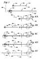
- FIG. 7illustrates the brachytherapy apparatus of FIG. 6 as it may be partially assembled
- FIGS. 8A-8Eare diagrammatic illustrations of a method of using the brachytherapy apparatus of FIGS. 6 and 7 ;
- FIGS. 9A-9Bare enlarged partial views of a brachytherapy device in accordance with another embodiment of the invention.
- FIGS. 10A-10Bare enlarged partial views of a brachytherapy device in accordance with yet another embodiment of the invention.
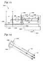
- FIGS. 11A-11Bare enlarged partial views of a brachytherapy device in accordance with still yet another embodiment of the invention.
- FIGS. 12A-12Bare enlarged partial views of a brachytherapy device in accordance with still another embodiment of the invention.
- FIGS. 13A-13Bare enlarged partial views of a brachytherapy device in accordance with yet another embodiment of the invention.
- FIGS. 14A-14Bare enlarged partial views of a brachytherapy device in accordance with still yet another embodiment of the invention.
- FIG. 15is a diagrammatic view of a brachytherapy apparatus in accordance with another embodiment of the invention.
- FIGS. 16A-16Gare diagrammatic illustrations of non-linear brachytherapy apparatus and methods in accordance with various embodiments of the invention, where FIGS. 16A-16E illustrate a dual, off-axis catheter assembly; and FIGS. 16F-16G illustrate a spiral-shaped catheter;
- FIGS. 17A-17Billustrate a brachytherapy apparatus in accordance with yet another embodiment of the invention.
- FIG. 18is a view of a radiation attenuating garment, e.g., brassiere, in accordance with one embodiment of the invention.
- FIGS. 19A-19Care diagrammatic views of a balloon catheter assembly, e.g., HDR catheter, in accordance with one embodiment of the invention.
- FIG. 20is an exemplary embodiment of a delivery or implantation system for use with the brachytherapy methods and apparatus described herein;
- FIG. 21is a diagrammatic view of the delivery system FIG. 20 as it may be used with the brachytherapy methods and apparatus described herein, e.g., the methods described in FIGS. 2A-2F and 8 A- 8 E;
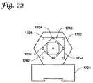
- FIG. 22is an enlarged view of an exemplary catheter, e.g., needle, guiding template for use with the delivery system of FIG. 21 ;
- FIG. 23is diagrammatic view of another delivery or implantation system for use with the brachytherapy methods and apparatus described herein;
- FIG. 24is an exploded view of a portion, e.g., a cartridge, of the delivery system of FIG. 23 ;
- FIGS. 25A-25Dare diagrammatic illustrations of a delivery or implantation system and method in accordance with yet another embodiment of the invention.
- FIG. 26is a view of a portion of a human body, e.g., a female breast, after the brachytherapy devices as described herein have been implanted and secured; and
- FIG. 27is a cross-section of a portion of the delivery system of FIGS. 25A-25D .
- the present inventionis directed to brachytherapy apparatus and methods. More particularly, the present invention provides a system for delivering one or more therapeutic elements (e.g., radiation sources) relative to a target tissue region.
- the radiation sourcesmay be either immediately withdrawn (e.g., in HDR applications), or left in place, e.g., implanted, for a defined period (e.g., in LDR applications). In either instance, the radiation sources may deliver therapy to the target tissue region in accordance with a predefined therapy profile.
- LDR radiation sourcesmay be implanted and secured to the body or target tissue in such a way as to prevent or substantially limit movement of the sources relative to the target tissue.
- apparatus and methods of the present inventionprovide not only indwelling therapy using pre-arranged packages of radioactive sources, e.g., seeds, but also allow easy removal of the radiation sources at the completion of brachytherapy.
- radiation sourcemay include most any therapeutic element operable to deliver a dose of radiation.
- the radiation sourcemay be a radioactive seed or, alternatively, a LDR or HDR wire element (e.g., Iridium wire).
- implantableindicates the capability of a device to be inserted into the body and then maintained in a fixed or static position, relative to the immediately surrounding tissue, for an extended period of time, e.g., an hour or more and, more preferably, several hours or more.
- target tissuemay include most any portion of a human (or other mammalian) body that has been identified to benefit from radiation therapy.
- the target tissue regionmay be a tumor or lesion itself, tissue proximate or surrounding the tumor, or a cavity created by tumor excision (such as the surrounding tissue associated with a lumpectomy cavity of the breast).
- the apparatus and methods of the present inventionmay also have application to HDR brachytherapy (e.g., HDR catheters) as further described below.
- HDR brachytherapye.g., HDR catheters
- the present inventionmay have application to other therapy regimens that benefit from the removable implantation of therapy-delivering elements.
- the inventionis described herein as it relates to the treatment of breast cancer.
- this particular applicationis not limiting. That is, those of skill in the art will readily appreciate that the systems, apparatus, and methods described herein may find application to most any cancer that may receive benefit from brachytherapy.
- FIG. 1illustrates an exemplary kit or apparatus 100 for providing brachytherapy to a target tissue region of a body.
- the apparatus 100may include an elongate and flexible, removably implantable brachytherapy treatment device 102 (also referred to hereinafter as “brachytherapy device 102 ”) having a therapy delivery portion 104 , and an elongate and flexible tail portion 106 .
- the tail portion 106may, as further described below, provide the ability to remove the device 102 at therapy completion.
- Other components described below, e.g., locking members,may also be included with the apparatus 100 .
- flexibleis used herein to describe a component that is highly pliant, e.g., a component that may be substantially and easily bent, flexed, and/or twisted without experiencing breakage or permanent deformation.
- the therapy delivery portion 104may form a carrier pod of therapeutic elements, e.g., radiation sources such as radioactive seeds 108 , secured relative to one another and to the therapy delivery portion 104 .
- One or more spacers 110may optionally be located between each seed 108 to obtain the desired seed separation.
- the seeds 108may be produced from most any acceptable radioactive source now known (e.g., radioactive Palladium or Iodine) or later developed. Typically, numerous seeds 108 are provided and precisely placed along the length of the therapy delivery portion 104 in order to correspond to the desired therapy delivery regimen. While the radioactive sources are described herein as seeds 108 , they may take other forms such as a continuous filament (or numerous discontinuous segments) of radioactive wire (e.g., Iridium wire).
- the brachytherapy device 102may include a flexible casing or casing member, illustrated in the figures as tube or tube member 112 , in which the seeds 108 and optional spacers 110 are securely retained.
- the casingis made from a non-dissolving and flexible, heat-shrinkable tubing material.
- Heat-shrinkable tubingrefers to tubing, such as various plastic tubing, in which subsequent thermal exposure causes the tubing to shrink, thereby allowing it to securely retain the seeds 108 in place.
- Exemplary heat-shrinkable materialsinclude polyester, fluorinated polymers, and polyolefins.
- the tube 112may have an initial inside diameter of about 1 mm and a wall thickness of about 0.05 mm. Once heated, the tube 112 may shrink (if unconstrained) to an outer diameter ranging from about 0.3 mm to about 0.6 mm.
- the casingis described herein generally as tube-shaped, the casing may, in other embodiments, be most any shape that is capable of effectively securing the individual seeds 108 relative to the casing and to one another.
- the tubemay be shrunk by exposure to heat, thus contracting the tube 112 around the seeds 108 .
- the tail portion 106may be formed by an integral portion, e.g., extension, of the casing (tube 112 ) that extends beyond the seeds 108 . To reduce the diameter of the tail portion 106 , it may also be thermally treated (shrunk).
- Other embodimentsmay utilize a two-part brachytherapy device, e.g., a separate filament tail portion attached to the therapy delivery portion.
- the brachytherapy devices 102 described hereinprovide not only proper spacing of the seeds 108 , but also facilitate subsequent seed identification and removal. Moreover, because the seeds are contained within the pod defined by the therapy delivery portion 104 , seeds may not require individual handling, thus simplifying inventory and handling prior to, and at the time of, implantation.
- the components of the device 102are preferably constructed of non-dissolving materials.
- non-dissolvingis used herein to indicate most any material that does not substantially deteriorate or otherwise break down during the implantation period.
- the brachytherapy apparatus 100may also include a catheter, e.g., needle 114 . While illustrated as needle 114 , any other type of catheter, such as the cannulae described further below, may also be used without departing from the scope of the invention.
- the needle 114defines a lumen 115 of sufficient size to allow the therapy device 102 to pass through as indicated in FIG. 1 .
- the needle 114in some embodiments, may further include a hub 116 at a proximal end to assist with manipulation of the needle and insertion of the therapy device 102 .
- a distal end of the needle 114may form a sharpened tip 117 operable to pierce the body as further described below.
- the needle 114may be made from most any suitable biocompatible material. For example, it may be made from metal, e.g., stainless steel, titanium, or nickel titanium alloy. It may also include a removable outer sheath (not shown) made of plastic, e.g., fluorinated polymers.
- FIGS. 2A-2Eillustrate an exemplary method of using the brachytherapy apparatus 100 of FIG. 1 .
- the needle 114may be inserted into the body 200 , as shown by arrow 203 in FIG. 2A , to a predetermined depth.
- the relative location(s) of the needle 114 and/or the target tissue region 202may be determined by most any method, e.g., via ultrasound, CT scan, stereotactic X-ray, etc.
- the needle 114may further be aligned with the use of a needle guiding template as further described below, or by other techniques.
- the brachytherapy device 102may be inserted into the lumen 115 of the needle 114 , as shown by arrow 205 in FIG. 213 , until the therapy delivery portion 104 is located at the desired depth relative to the target tissue region 202 as shown in FIG. 2C .
- the tail portion 106may include measurement demarcations 118 .
- Other location verification techniquese.g., X-ray, ultrasound, etc., may also be used.
- the needle 114may be withdrawn from the body in the direction 207 as shown in FIG. 2D , leaving the therapy delivery portion 104 of the device 102 at the desired position within the body 200 .
- the tail portion 106is preferably of sufficient length such that it extends outside of the body 200 as shown in FIG. 2E . That is, the tail portion 106 may extend externally through a puncture made by the needle 114 .
- a locking member 120may be crimped or otherwise attached to the tail portion 106 of the therapy delivery device 102 immediately adjacent the associated puncture in the body 200 .
- the locking member 120may assist in maintaining the location of the therapy delivery portion 104 relative to the target tissue region 202 . While most any locking member may be used, one embodiment utilizes a malleable, hat- or U-shaped lock that can be easily and securely crimped to the tail portion with, for example, a surgical clip applier or similar tool. An enlarged view of an exemplary locking member is illustrated in FIG. 27 .
- FIGS. 2A-2EFor illustration purposes, only a single therapy delivery device 102 is shown in FIGS. 2A-2E . However, in practice, multiple devices would be utilized to provide adequate dosage to the target tissue region 202 .
- the actual number of devices 102may vary depending on various parameters such as lesion size, radiation source activity levels, and proximity to other organs/vulnerable tissue (e.g., skin, chest wall). However, quantities ranging from about 5 to about 25 devices are contemplated.
- FIG. 2Fillustrates a variation of the therapy device 102 of FIGS. 2A-2E that may offer additional benefits, especially to the treatment of breast cancers.
- a therapy device 152similar in most respects to the device 102 is provided.
- the device 152may include both a first tail portion extending from a first end of a therapy delivery portion 154 and a second tail portion extending from a second end, i.e., it may include a tail portion 156 at each end of the therapy delivery portion 154 .
- the needle 114may pass completely through the body, e.g., breast 200 , such that one tail portion 156 extends out the opposite side of the breast 200 .
- locking members 120may be secured at two locations relative to the target tissue region 202 , thus preventing or substantially limiting movement of the therapy delivery portion 154 relative to the target tissue region 202 .
- the devices of the present inventione.g., devices 102
- the devices of the present inventionmay be about 1 mm or less in diameter at the therapy delivery portion 104 and even smaller at the tail portion 106 .
- This constructionpermits the devices 102 to be relatively small and flexible, and thus less obtrusive to the patient.
- the size and flexibility of the tail portions 106may be similar to that of a conventional suture.
- securing the tail portions 106may be accomplished in any number of ways including, for example, folding the tail portions against the contour of the surrounding body and fixing them such as by tying the ends and/or securing the ends with adhesive, the latter represented by bandage 2600 in FIGS. 2E and 26 .
- FIG. 3Ais an enlarged view of the therapy device 102 of FIG. 1 .
- the therapy device 102may include the therapy delivery portion 104 and the tail portion 106 .
- the therapy delivery portion 104may include one, or preferably more, radioactive seeds 108 separated by spacers 110 and encased within the casing, e.g., heat-shrinkable tube 112 .
- the tail portion 106may be formed by the portion of the tube 112 that does not surround the seeds 108 .
- the conformal properties of the tube 112may be sufficient to ensure proper seed spacing, thus negating the need for spacers 110 .
- FIG. 3Billustrates a section view through a seed 108 and the tube 112 taken along line 3 B- 3 B of FIG. 3A .
- FIGS. 4A-4Billustrate a therapy device 402 in accordance with another embodiment of the present invention.
- the device 402is similar in many respects to the device 102 described above.
- the device 402may include a therapy delivery portion 404 and a tail portion 406 as illustrated in FIG. 4A .
- a casing, e.g., heat shrinkable tube 412may be used to encase the seeds 108 and optional spacers 110 as well as to form the tail portion 406 .
- the tube 412may include a radioabsorptive portion 414 , e.g., a substance or liner, positioned along a portion of the circumference of the therapy delivery portion 404 (see FIG.
- the radioabsorptive portion 414may include a radiation attenuating material, and thus reduce radiation exposure to tissue blocked by the radioabsorptive portion 414 as opposed to tissue not blocked by the portion 414 .
- the radioabsorptive portionmay be formed by a substance (e.g., Tungsten, Nickel-Titanium alloy, stainless steel) applied to, or impregnated within, a portion of the tube 412 .
- the radioabsorptive portion(s)may be formed by a liner within, or secured to a portion of, the tube 412 .
- FIG. 4Billustrates a section view through a seed 108 and the tube 412 taken along line 4 B- 4 B of FIG. 4A .
- radiotransparentis used herein to indicate only that the identified portion of the apparatus or device is relatively more transparent to radiation than the portion identified as “radioabsorptive.”
- FIGS. 5A-5Billustrate a therapy device 502 in accordance with yet another embodiment of the present invention.
- the device 502is similar in many respects to the device 102 described above.
- the device 502may include a therapy delivery portion 504 and a tail portion 506 as shown in FIG. 5A .
- a casinge.g., heat shrinkable tube 512
- the therapy device 502may incorporate an anchor member, e.g., a flat or round cross-section anchor wire 514 , which extends along at least a part of the therapy delivery portion 504 .
- the anchor wire 514protrudes from one or both ends of the therapy delivery portion and may be bent to form one or more hooks or anchors 516 .
- FIG. 5Billustrates a section view through a seed 108 and the tube 512 taken along line 5 B- 5 B of FIG. 5A .
- the therapy device 102may be removed in any number of ways.
- the device 102may be removed by first removing any dressing (e.g., bandage 2600 of FIG. 2E ) and locking member(s) 120 , and then simply applying a pulling force to one of the tail portions 106 that extends outside of the body 200 .
- the devices 102may be removed prior to or during excisional surgery of the tumor 202 via known methods, e.g., via methods similar to excision utilizing localization wires.
- a removal catheter 550 as shown in FIG. 5Cmay be used.
- the removal catheter 550is similar in most respects to the delivery cannulae and needles described herein, e.g., needle 114 .
- the catheter 550may be threaded over the tail portion 106 and advanced until it encompasses the therapy delivery portion 104 .
- the removal catheter 550may be advanced until its distal end engages the distal retaining element(s), e.g., distal anchor 516 of FIG. 5A . Further advancement of the removal catheter 550 may bend the anchor sufficiently to permit the therapy delivery portion to slide into the removal catheter as shown in the broken line representation of FIG. 5C .
- the device 502 and the removal catheter 550may then be withdrawn as a unit from the body.
- the time that the brachytherapy devices remain implantedmay vary according to the desired therapy regimen. While not wishing to be bound to any fixed period, implantations from about one hour up to about eight weeks or more are contemplated for therapy. However, for breast brachytherapy, implantation periods ranging from about one day to several weeks are more likely. Moreover, because of the construction of the devices, e.g., devices 102 , they may be removed over a range of timeframes subsequent to implantation. This is in contrast to the permanent placement associated with conventional LDR brachytherapy and the short exposure time associated with conventional HDR brachytherapy. As a result, intermediate activity radiation sources may be utilized with the methods and apparatus of the present invention, as well as conventional low and, as further described below, high activity sources.
- FIG. 6illustrates a brachytherapy kit or apparatus 600 in accordance with another embodiment of the invention.
- the apparatus 600may include, among other components, at least a removably implantable brachytherapy treatment device (brachytherapy device 602 ), a pusher or pusher member 620 , a catheter, e.g., cannula or cannula member 630 , and a sharp obturator 640 .
- the therapy device 602may include a therapy delivery portion 604 and a removal or tail portion 606 .
- the therapy delivery portion 604may include one or more seeds 108 and optional spacers 110 .
- the seeds 108may be enclosed within a casing, e.g., heat-shrinkable tube or tube member 612 , similar in most respects to the tube 112 described above.
- the tail portion 606 in this embodimentis formed by an elongate filament or wire, e.g., a non-dissolving surgical suture 614 , coupled or otherwise attached to the therapy delivery portion 604 . While most any method of attaching the suture 614 to the therapy delivery portion 604 is possible, one embodiment forms a knot 616 in the suture. The knot 616 may be captured when the tube 612 is heat-shrunk to the therapy delivery portion 604 . In other embodiments, the suture 614 may be knotted around or otherwise attached directly to the therapy delivery portion 604 . Such suture attachment methods are exemplary only, however, as most any other method of attaching the suture 614 to the therapy delivery portion 604 is possible.
- the suture 614as with the tail portion 106 described above, is preferably made from a non-dissolving material, e.g., polypropylene, polyester, polyamide.
- the pusher member 620may include a lumen through which the therapy device 602 may pass as indicated in FIGS. 6 and 7 .
- the pusher membermay include a suture locking device 622 , e.g., a luer hub, at a proximal end to assist with loading and securing of the therapy device 602 .
- the locking device 622may secure the suture 614 relative to the pusher 620 as further described below. While illustrated as a luer hub, the locking device 622 may include most any friction or clamping device known in the art.
- the locking devicemay be an O-ring that may be selectively compressed to pinch the suture 614 .
- the cannula member 630may also include a lumen through which the pusher member 620 may pass as indicated in FIG. 6 .
- the cannula member 630may include a luer hub 632 at its proximal end that is operable to secure the cannula member relative to the either the sharp obturator 640 or the pusher member 620 when either is slid into the lumen of the cannula member as further described below.
- the sharp obturator 640may include a handle portion with a hub 642 at a proximal end, and a sharp point 644 operable to pierce body tissue at its distal end.
- the handle portionmay permit comfortable manipulation of the obturator 640 .
- the external diameter of the obturator 640may be sized so that it fits within the lumen of the cannula member 630 as indicated in FIG. 6 .
- the components of the apparatus 600may be made from most any suitable biocompatible material.
- the cannula member 630 , the pusher member 620 , and the sharp obturator 640may be made from metal, e.g., stainless steel or Titanium, or plastic.
- FIG. 7illustrates the apparatus 600 as it may be assembled prior to use.
- the sharp obturator 640may be placed into the cannula 630 such that the sharp distal end 644 of the obturator protrudes from the distal end of the cannula 630 as illustrated.
- the therapy device 602which includes the therapy delivery portion 604 and the suture 614 as described above, may be positioned within the pusher member 620 such that the therapy delivery portion 604 extends from its distal end and the suture 614 extends from the hub 622 at its proximal end.
- the suture 614may be pulled from the proximal end of the pusher member 620 until the therapy delivery portion 604 is at or near the distal end of the pusher member 620 as shown.
- the locking device 622may then be engaged to hold the suture 614 , and thus the therapy delivery portion 604 , in place relative to the pusher member 620 .
- FIGS. 8A-8Eillustrate an exemplary method of using the system 600 for delivery of brachytherapy to a portion of a body, e.g., breast 200 .
- the target tissue region 202e.g., tumor or tumor cavity
- the combined cannula 630 and sharp obturator 640may be advanced into the target tissue region 202 as illustrated by arrow 802 in FIG. 8A .
- the sharp obturator 640may be removed (moved in the direction 804 ) through the proximal end of the cannula as shown in FIG. 8B , while leaving the cannula 630 in place.
- the combined pusher member 620 and therapy device 602may then be inserted into the proximal end of the cannula 630 , in the direction 806 , as shown in FIG. 8C .
- the pusher 620 , and therapy device 602may be inserted until the therapy portion 604 is at its desired location, e.g., at or near the distal end of the cannula 630 .
- Location of the therapy portion 604may be assisted by image guidance, e.g., stereotactic X-ray, ultrasound, CT, etc.
- the cannula 630may be retracted (moved in the direction 808 ), exposing the therapy portion 604 to the target tissue region 202 as shown in FIG. 8D .
- the locking device 622may then be unlocked such that the pusher member 620 and cannula 630 may be fully withdrawn (moved in the direction 810 ) from the body 200 as shown in FIG. 8E .
- the therapy delivery portion 604remains implanted at the target tissue region 202 while the suture 614 extends outside the body.
- each brachytherapy device 602may be repeated for placement of each brachytherapy device 602 , or multiple devices may be implanted as a group as further described below.
- a locking membersuch as the locking member 120 illustrated in FIGS. 2E and 27 , may be used to secure the therapy device 602 , e.g., the tail portion(s) 606 , at one or both (see FIG. 2F ) ends.
- the therapy device 602may include securing elements such as the anchors 516 shown in FIG. 5 .
- the therapy device 602may be secured simply by folding and adhering the tail portions 606 to the breast 200 (see FIGS. 2E and 26 ).
- the therapy delivery device 102may be removed in any number of ways as already described herein, e.g., using a removal member, such as the tail portion 606 , or a removal cannula.
- FIG. 9Ais an enlarged view of the therapy device 602 of FIGS. 6-7 .
- the therapy device 602may include the therapy delivery portion 604 and the tail portion 606 .
- the therapy delivery portion 604may include one, or preferably more, radioactive seeds 108 securely retained within the casing, e.g., heat-shrinkable tube 612 .
- the tail portion 606may be formed by the suture 614 .
- the knot 616 of the suture 614may be secured to the therapy delivery portion 604 by the heat shrinkable tube 612 .
- FIG. 9Billustrates a section view of the seed 108 and tube 612 taken along line 9 B- 9 B of FIG. 9A .
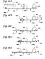
- FIGS. 10A-10Billustrate a therapy device 1002 in accordance with another embodiment of the present invention.
- the device 1002is similar in many respects to the device 602 described above.
- the device 1002may include a therapy delivery portion 1004 and a tail portion 1006 .
- a casing, e.g., heat shrinkable tube 1012may be used to encase the seeds 108 and optional spacers 110 .
- the tail portion 1006may be formed by a suture 614 having a knot 616 that may be heat shrinkable to the therapy delivery portion 1004 .
- the tube 1012may include a radioabsorptive portion 1014 positioned along a part of the circumference of at least the therapy delivery portion 1004 (see FIG. 10B ).
- the radioabsorptive portion 1014which may be formed integrally or separately with the tube 1012 , may limit radiation exposure to tissue blocked by the radioabsorptive portion.
- FIG. 10Billustrates a section view of the seed 108 and tube 1012 taken along line 10 B- 10 B of FIG. 10A .
- FIGS. 11A-11Billustrate a therapy device 1102 in accordance with yet another embodiment of the present invention.
- the device 1102is similar in many respects to the device 602 described above.
- the device 1102may include a therapy delivery portion 1104 and a tail portion 1106 .
- a casing, e.g., heat shrinkable tube 1112may be used to encase and constrain the seeds 108 and optional spacers 110 .
- the therapy device 1102may incorporate an anchor member, e.g., anchor wire 1114 , which extends along at least a part of the therapy delivery portion 1104 and protrudes from one or both ends.
- the anchor wire 1114may be bent at one or both ends to form anchors 1116 .
- FIG. 11Billustrates a section view of the seed 108 and tube 1112 taken along line 11 B- 11 B of FIG. 11A .
- any of the various components of the invention described hereinmay be used interchangeably with any of the described methods and systems.
- any one of the devices 102 , 402 , 502 , 602 , 1002 , and 1102could be used with the methods described in FIGS. 2A-2E , 2 F, and 8 A- 8 E without departing from the scope of the invention.
- the embodiments described aboveutilize a therapy delivery portion (e.g., portion 104 of FIG. 1 or portion 604 of FIG. 6 ) formed primarily by the shrink fit tube (e.g., tube 612 of FIG. 9A ) and seeds 108 .
- a therapy delivery portione.g., portion 104 of FIG. 1 or portion 604 of FIG. 6
- the shrink fit tubee.g., tube 612 of FIG. 9A
- the therapy delivery portionmay include an additional support member.
- the support membermay be any material that lends support to the therapy delivery portion, e.g., a strip of material such as stainless steel or superelastic nickel titanium alloy.
- the material of the support membermay divide the therapy delivery portion into a radiotransparent portion and a radioabsorptive portion.
- tissue on a side of the support member opposite the seeds 108may receive a lower dose of radiation than tissue on the seed side.
- the support membermay be enclosed within the casing, e.g., heat-shrinkable tube 112 or 612 .
- FIGS. 12A and 12Billustrate a therapy device 1202 having a tail portion 1206 and a therapy delivery portion 1204 with a plurality of seeds 108 and a straight support member 1210 (see FIG. 12A ).
- the support member 1210may have a curved, e.g., arc-shaped, cross-section (see FIG. 12B ). Alternatively, a relatively flat cross-section (not shown) may be provided. Other embodiments may utilize most any other cross-sectional shape, e.g., v-shaped.
- the support member 1210may also have a variety of leading edge shapes including the shovel-tip shape illustrated in FIG. 12A . Some or all of the support member 1210 may be encased within a casing, e.g., heat shrinkable tube 1212 , as already described above.
- FIG. 13Aillustrates a therapy device 1302 having a therapy delivery portion 1304 with a curved support member 1310 that imparts an arc- or otherwise curved-shape to the delivery portion 1304 .
- the support member 1310may be formed to have curvature in its relaxed state or may simply be sufficiently flexible to permit curved implantation. As with the support member 1210 of FIGS. 12A-12B , the support member 1310 may have most any cross-sectional shape, e.g., flat, curved (as shown in FIG. 13B ), V-shaped, etc. Some or all of the support member 1310 may be encased within a casing, e.g., heat shrinkable tube 1312 , generally identical to the casings already described above.
- FIG. 13Billustrates a section view taken along line 13 B- 13 B of FIG. 13A .
- support members in accordance with the present inventionmay include one or more slots, e.g., along a centerline, so that seeds may be placed at least partially within the slot.
- a therapy delivery portionthat offers more rigidity than the unsupported therapy delivery portions described herein may be obtained while ensuring tissue on both sides of the support member receives radiation treatment.
- FIGS. 14A-14Billustrate another exemplary embodiment of a therapy delivery portion 1404 .
- the therapy delivery portionincludes a catheter or casing, e.g., tube 1412 , having one or more lumens.
- a first or main lumen 1408may receive the seeds (not shown), while a second lumen 1414 may contain an attenuating or shielding element 1416 extending over a longitudinal length of the tube 1412 .
- the tube 1412may have a radiotransparent portion (that portion not blocked by the element 1416 ), and a radioabsorptive portion (that portion shielded by the element 1416 ).
- the tube 1412can be made by co-extruding plastic (e.g., fluoropolymer) with an attenuating material such as strands of fine metallic wire (e.g., stainless steel, gold).
- the attenuating materialmay be a coextrusion of polymer loaded with an attenuating material such as Tungsten powder.
- the tube 1412may or may not be heat-shrinkable.
- the shielding element 1416may be straight or preformed in a curve.
- FIG. 14Billustrates a section view taken along line 14 B- 14 B of FIG. 14A .
- FIG. 15is a partial view of an exemplary brachytherapy apparatus 1500 having a therapy device 1502 and catheter, e.g., cannula 1501 , wherein the device 1502 includes a curved therapy delivery portion 1504 , and a tail portion 1506 .
- Other components of the systeme.g., pusher member and sharp obturator, are not illustrated in this view.
- the curved therapy delivery portion 1504may be formed by a curved support member such as support member 1310 of FIG. 13A .
- the cannula 1501preferably has a lumen diameter sufficiently large to accommodate the curved therapy delivery portion 1504 when the latter is constrained in a straightened configuration for delivery.
- the cannula 1501may be sized to receive the therapy delivery portion 1504 when the latter is in its curved configuration.
- the therapy delivery portion 1504may be generally straight but flexible and the cannula 1501 used to deliver the therapy delivery portion may be curved.
- Non-linear (e.g., curved) cathetersmay also be used for delivery and placement of the brachytherapy devices described herein to regions and positions inaccessible to straight catheters.
- FIGS. 16A-16Eillustrate an exemplary apparatus 1650 and method operable to implant a brachytherapy device, e.g., device 102 of FIG. 1 , along a non-linear axis.
- FIG. 16Aillustrates the apparatus 1650 including a first catheter member, e.g., needle 1652 , a second catheter member, e.g., flexible catheter 1656 , and a brachytherapy device 102 .
- the needle 1652includes an off-axis opening 1654 at or near a distal end of the needle.
- the needle 1652may be inserted into the body 200 , in the direction 1651 , until the distal end is positioned past the target tissue region 202 as shown in FIG. 16A .
- the flexible catheter 1656may then be inserted through the needle 1652 (in the direction 1653 ) until a distal end 1667 of the catheter 1656 protrudes from the opening 1654 of the needle 1652 at an angle 1661 as shown in FIG. 16B . That is, an axis of the catheter 1656 may intersect, or be otherwise nonparallel to, an axis of the needle 1652 .
- the angle 1661 between the axesmay vary, but angles ranging from greater than about 0 degrees to about 90 degrees, and more preferably about 5 degrees to about 35 degrees, are contemplated.
- the device 102may then be threaded through the catheter 1656 (in the direction 1655 ), as shown in FIG. 16C , until the therapy delivery portion of the device 102 is located at or near the distal end 1667 of the catheter 1656 .
- the catheter 1656may be withdrawn slightly (in the direction 1669 ) as shown in FIG. 16D , exposing the therapy delivery portion of the device 102 .
- the needle 1652 and catheter 1656may then be withdrawn (in the direction 1671 ) from the body 200 together as shown in FIG. 16E .
- the device 102is then implanted on a non-linear axis with its tail portion 106 extending outside the body as generally described above with reference to other embodiments (see e.g., FIGS. 2A-2E ).
- the ability to implant the device 102 along a non-linear axismay be beneficial in many applications.
- the non-linear device 102may provide the capability to better focus radiation.
- non-linear positioningmay permit implantation around obstructions in the body.
- the region 202could be a pubic arch around which the clinician desires to place radiation sources. While described above with respect to devices 102 , the non-linear placement of FIGS. 16A-16E could also be used to implant individual radiation sources.
- the needle 1652 of FIGS. 16A-16Emay be replaced with a more spiral-shaped needle 1675 as shown in FIGS. 16F and 16G .
- the actual needle sizemay vary depending on target tissue volume, needles having a helix diameter of about 3 centimeters (cm) are contemplated.
- the needle 1675may be advanced into the body 200 in much the same way a corkscrew is inserted into a cork. That is, the needle 1675 may be rotated in a direction 1678 such that a sharp end 1676 penetrates the body 200 as indicated in FIG. 16F .
- FIG. 16Gillustrates the needle 1675 once it is fully inserted.
- a flexible catheter (not shown) and therapy device (also not shown)may then be passed through the needle 1675 in much the same way as the catheter 1656 and device 102 are described with reference to FIGS. 16A-16E .
- the needle 1675may then removed (“unscrewed”), leaving the therapy device in a spiral configuration around the target tissue region 202 (not illustrated).
- the total number of therapy devices required to treat a given target tissue regionmay potentially be reduced as a result of the delivery portions' conformance to the shape of the target tissue.
- the delivery portionsmay potentially be reduced as a result of the delivery portions' conformance to the shape of the target tissue.
- several devicesmay be placed to curve around the target tissue region, effectively focusing radiation on a central area. This may result in lower dose exposure outside of the target tissue area, and potentially improved dose coverage within the target tissue.
- a single therapy device of sufficient lengthmay deliver adequate treatment by spiraling (e.g., forming a helix) around or within the target tissue region.
- FIGS. 17A-17Billustrate an apparatus 1600 similar in most respects to apparatus 600 of FIG. 6 .
- itmay include a therapy device 1602 having a therapy delivery portion 1604 with seeds 108 , and tail portion formed by a suture 1614 .
- the suture 1614may pass through a pusher member 1620 and the combined pusher member 1620 and delivery device 1602 may be placed within a cannula 1630 .
- the cannula 1630may have a cutout 1634 , e.g., the cannula may have a C-shaped cross section, as shown more clearly in FIG. 17B , over at least a portion of its length.
- FIG. 17Bis a cross-section taken along line 17 B- 17 B of FIG. 17A with the therapy delivery device 1602 also shown in broken lines.
- the patientmay optionally wear a protective garment, e.g., a chest covering brassiere or binder 1900 , such as that illustrated in FIG. 18 .
- the brassiere/binder 1900may be similar in many respects to those garments described, for example, in U.S. Pat. No. 3,968,803 to Hyman; U.S. Pat. No. 5,152,741 to Farnio; and U.S. Pat. No. 5,538,502 to Johnstone. That is, it may include a partial body covering that secures via fasteners, e.g., shoulder straps 1904 , to cover a portion of the chest (or other area surrounding the target tissue region).
- fastenerse.g., shoulder straps 1904
- the binder 1900may include a lining made from a radiation attenuating material 1902 , e.g., lead, stainless steel, Tungsten.
- a radiation attenuating material 1902e.g., lead, stainless steel, Tungsten.
- Such a garmentmay offer an added degree of shielding and permit greater patient mobility, while the radioactive sources, e.g., seeds 108 , are indwelling, in an out-patient setting.
- the garment 1900may be provided separately, or as part of a brachytherapy kit, e.g., kit 100 .
- the tube 1412 of FIGS. 14A-14Bmay be used as a shielded delivery catheter for HDR treatment, e.g., the tube 1412 may be located in the body and a conventional HDR source (e.g., afterload HDR cable) of smaller diameter may be passed through the main lumen 1408 .
- a conventional HDR sourcee.g., afterload HDR cable
- the attenuating element 1416 in the wall of the cathetermay attenuate the radiation exposure of regions vulnerable to radiation while the non-shielded section of the tube 1412 (along a circumferential portion extending from about 2 o'clock to about 10 o'clock) would allow exposure to the target tissue.
- HDR radiation sourcesmay be passed through a catheter, e.g., the cannula 1630 of FIGS. 17A and 17B , whereby the HDR radiation sources may be partially shielded from surrounding tissue by the geometry of the cannula 1630 , e.g., the cutout 1634 .
- FIGS. 19A-19Cillustrate incorporation of a HDR shielded catheter in accordance with the present invention on a balloon-type brachytherapy treatment device 1800 .
- the device 1800may be similar to the device disclosed in U.S. Pat. No. 5,913,813 to Williams et al. That is, it may include a brachytherapy catheter assembly 1802 having a catheter shaft 1814 with a proximal end and a distal end.
- An inflatable balloon 1806may be coupled to the catheter shaft 1814 between the proximal end and the distal end.
- An inflation lumen 1830may extend along the catheter shaft 1814 between the inflatable balloon 1806 and the proximal end to allow inflation of the balloon.
- a dose delivery lumen 1804(see FIG. 19B ) may also be provided and extend along the catheter shaft 1814 from the proximal end towards and the distal end, e.g., extending between the inflatable balloon 1806 and the proximal end.
- the distal end of the catheter shaft 1814may be placed into a cavity, e.g., a lumpectomy cavity 1808 of breast 200 , and the balloon 1806 inflated.
- a radiation source(not shown) may then be passed through the dose delivery lumen 1804 , where it delivers radiation along a dose delivery portion of the catheter shaft, e.g., along a portion surrounded by the inflatable balloon 1806 .
- a radioabsorptive portione.g., arc-shaped member 1811 clearly illustrated in FIG. 19C
- only a predetermined portion, e.g., a window 1817of the dose delivery portion may be relatively radiotransparent.
- the device 1800may attenuate the radiation exposure of select areas, e.g., those close to the skin or chest wall, while delivering higher radiation levels to target tissue not blocked by the radioabsorptive portion 1811 .
- the radioabsorptive portionis illustrated herein as a separate member 1811 extending along a portion of the catheter shaft 1814 , other embodiments may incorporate the radioabsorptive portion into the catheter shaft 1814 itself (see. e.g., the catheters described elsewhere herein such as the tube 1412 of FIGS. 14A-14B ).
- the device 1800may further include a vent system having one or more vents 1810 positioned around at least a portion of an outer surface of the balloon 1806 .
- the vents 1810may permit air and fluids within the cavity 1808 to escape as the balloon 1806 expands.
- One or more vent lumens 1812(shown in FIG. 19B ) associated with the catheter shaft 1814 may extend between the proximal end of the catheter shaft 1814 and the one or more vents 1810 .
- the vents 1810may fluidly communicate with one or more vent lumens 1812 , thereby allowing the air and fluids to exit the body at the proximal end of the catheter shaft 1814 during and after balloon expansion.
- the external vents 1810 and vent lumens 1812are formed by individual pieces of tubing 1816 attached to the balloon 1806 and catheter shaft 1814 .
- the tubing 1816may be perforated to form the external vents 1810 .
- the portion of the tubing 1816 located proximate the catheter shaft 1814may or may not include perforations.
- the tubing 1816may be formed of most any biocompatible material that can be securely attached to, or formed with, the balloon 1806 and catheter shaft 1814 , e.g., silicone tubing.
- FIGS. 20-22illustrate an exemplary system 1700 for implanting the LDR brachytherapy devices and their associated radiation sources described above to a target tissue region, e.g., the region surrounding a breast lumpectomy cavity.
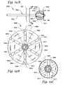
- the systemincludes a catheter or needle guiding template 1702 having a predetermined number and pattern (array) of openings 1704 as shown in FIG. 20 .
- the template 1702may form part of an adjustable catheter or needle guiding apparatus by coupling to a stereotactic table 1720 , which is diagrammatically illustrated in the figures by base portion 1722 , and translating portion 1724 (portions 1722 and 1724 shown exploded in FIG. 20 ).
- the stereotactic table 1720is preferably coupled or attached to a patient locating or treatment surface 1730 , e.g., patient table.
- the template 1702may be coupled to, or otherwise associated with, a first compression member 1726 located adjacent an opening 1732 in the treatment surface 1730 .
- An opposing second compression member 1728may be located on an opposite side of the opening 1732 .
- the compression members 1726 and 1728may be oriented about 90 degrees from a set of optional compression plates 1727 (only one plate 1727 shown).
- One or both compression members 1726 , 1728may include a hole pattern similar to that of the template 1702 , or may otherwise at least permit the passage of the needles/cannulae (e.g., needles 114 of FIG. 1 ) as illustrated in FIG. 21 .
- a patientmay lie on the treatment surface 1730 , e.g., with the patient's head located in the direction 1731 , such that the breast 200 passes through the opening 1732 of the treatment surface 1730 .
- the optional compression plates 1727may then be used to immobilize the breast 200 .
- the stereotactic table 1720may be positioned, and the translating portion 1724 moved, until the compression members 1726 and 1728 contact the breast 200 .
- the position of the stereotactic table 1720 , and thus the needle guiding template 1702may be aligned with the location of the target tissue region 202 via the use of various imaging techniques including, for example, X-ray, ultrasound and CT scan.
- the template 1702may be aligned relative to the target tissue region based upon input provided by an imaging device, e.g., a side viewing ultrasound apparatus 1739 , located underneath the breast 200 .
- one or more needles 114may be inserted into the openings 1704 .
- the needles 114may be inserted completely through the breast 200 as illustrated in FIG. 21 .
- the length of each needle 114may be varied to ensure the correct depth penetration at each opening 1704 , or the insertion depth of each needle 114 may simply be varied.
- Certain embodiments of the system 1700may optionally include an adhesive bandage member 1750 associated with the first compression member 1726 , and/or an adhesive bandage member 1752 associated with the second compression member 1728 .
- the bandage members 1750 and 1752are located between the respective compression members and the breast 200 .
- the bandage members 1750 and 1752may have adhesive on each side, e.g., a first side 1754 and a second side 1756 , and include openings (not shown) that correspond generally to the openings 1704 of the template 1702 .
- the bandage members 1750 and 1752may be punctured by the needles 114 during needle insertion. When the compression members 1726 and 1728 are pressed against the breast 200 , the bandage members 1750 and 1752 may adhere to the breast 200 and provide a dressing for the punctures created by the needles 114 .
- the brachytherapy devices described hereine.g., devices 102 or 602
- the brachytherapy devices 102may be inserted, and the needles 114 removed, in accordance with various methods as described and illustrated herein.
- the brachytherapy devices 102(or devices 602 ) may be inserted and the needles 114 (or the cannulae 630 ) removed in accordance with the methods described herein and illustrated in FIGS. 2A-2E and 2 F (or 8 A- 8 E).
- the template 1702 and contact plates 1726 and 1728may be withdrawn from the breast 200 , leaving the bandage members 1750 and 1752 adhered to the breast by their respective first adhesive sides 1754 .
- the tail portions 106may then be anchored, e.g., by using locking members such as members 120 illustrated in FIGS. 2E and 27 .
- a liner(not shown) may then be removed from the respective second adhesive side 1756 of each bandage member 1750 and 1752 . Once the second adhesive side 1756 is exposed, the flexible tail portions 106 may be folded against the second adhesive side, where they adhere thereto.
- a second, single-sided adhesive member(not shown) may be placed over each bandage member 1750 and 1752 to secure the tail portions and cover any exposed adhesive on the second adhesive side 1756 . As a result, the flexible tail portions may be folded against the contours of the breast and secured.
- the openings 1704 of the template 1702may be grouped according to a particular target tissue volume, e.g., lesion size, as shown in FIG. 22 .
- a small square, five-opening pattern 1740may be utilized for small target tissue regions (e.g., those regions up to about 1 centimeter in diameter), while a larger nine-opening pattern 1742 may be utilized for larger target tissue regions (e.g., those regions up to about 2 cm in diameter).
- a still larger, thirteen-opening patternmay be utilized for even larger target tissue regions (e.g., those regions up to about 3 cm in diameter).
- the templatemay indicate a standard number of seeds, e.g., a particular number of therapy devices 102 , based upon the predetermined target volume. This could simplify, or possibly eliminate, the need for complex dose mapping calculations commonly associated with conventional brachytherapy methods.
- the patterns 1740 , 1742 , and 1744are exemplary only. In other embodiments, the patterns may include most any number of openings 1704 in most any shaped pattern, e.g., a circular array of 5 to 50 catheters. Moreover, the templates could accommodate more that one diameter catheter or needle (e.g., 10, 15, and 20 mm diameters). Moreover, while shown with three patterns, templates having most any number are possible without departing from the scope of the invention.
- FIGS. 23 and 24illustrate another system for implanting brachytherapy devices of the present invention.
- FIG. 23illustrates a system 2300 similar in many respects to the system 1700 described above.
- the system 2300may include a stereotactic table 2320 secured to treatment surface, e.g., patient table (not shown).
- the table 2320may include a base portion 2322 and a translational portion 2324 .
- the system 2300may also include a first or proximal compression member 2326 and a second or distal compression member 2328 .
- One or both compression members 2326 and 2328may be movable relative to the other and/or the base portion 2322 , e.g., along a slide rail 2329 .
- the system 2300may also include a catheter or needle cartridge receiver 2340 operable to receive a pre-assembled needle cartridge 2342 having multiple needles 114 positioned in a predetermined array.
- the needle cartridge 2342is shown in an exploded view in FIG. 24 .
- the cartridge 2342may include a first holder 2344 and a second holder 2346 (second holder 2346 not shown in FIG. 24 ).
- the holders 2344 and 2346may include holes 2348 to hold and guide the multiple needles 114 in the desired predetermined array during insertion.
- needles 114include a hub 116
- the holes 2348 in the holder 2346may be larger than the corresponding holes 2348 in the holder 2344 to permit the passage of the hub 116 (see FIG. 23 ).
- the stereotactic table 2320may be aligned as described above with respect to the system 1700 .
- the breast 200may be immobilized with the compression members 2326 and 2328 .
- a specific cartridge 2342may be selected and pre-assembled with a corresponding number of catheters, e.g., needles 114 .
- the cartridge in FIG. 24is a 5 catheter configuration.
- other cartridgesmay utilize more or less catheters (e.g., 9 catheter and 13 catheter cartridges).
- the cartridge 2342including the holders 2344 and 2346 and the catheters 114 , may then be loaded into the cartridge receiver 2340 . Portions of the holders 2344 and 2346 may be designed to contact one or more internal surfaces of the cartridge receiver 2340 so that the cartridge 2342 aligns with the cartridge receiver upon insertion.
- each needle 114may be independently and manually advanced through the proximal compression plate 2326 (which may include a hole pattern identical to the holder 2344 ), the breast 200 , and the distal compression member 2328 .
- the central needle 114may be advanced first and its position within the target tissue region 202 confirmed (or repositioned) before the remaining needles are advanced.
- Brachytherapy devicese.g., devices 102 of FIG. 1 , may then be placed into the needles 114 as described in FIGS. 2A-2E . Alternatively, the devices 102 could be pre-installed in the cartridge 2342 .
- the distal tips of the tail portionsmay be temporarily secured relative to the distal compression member 2328 .
- the needles 114may be retracted and removed from the breast 200 , and ultimately, withdrawn from the cartridge loader 2340 .
- the proximal compression member 2326may then be withdrawn and the proximal tail portions secured to the breast using, for example, the locking devices 120 described above and illustrated in FIGS. 2E and 27 .
- the distal compression member 2328may then be withdrawn and the distal tail portions secured relative to the breast 200 in a similar manner.
- FIGS. 25A-25Dillustrate yet another system and method for inserting the brachytherapy devices of the present invention into a target tissue region.
- FIG. 25Aillustrates a system 2500 similar in many respects to the systems 1700 and 2300 described above.
- the system 2500includes a stereotactic table (not shown) having a catheter or needle cartridge receiver 2540 coupled thereto.
- the stereotactic tableis preferably coupled to the treatment table (also not shown).
- the system 2500may also include a catheter or needle cartridge 2542 .
- the needle cartridge 2542may include a series of needles 2514 , e.g., 5, 9, or 13 needle array, which are generally rigidly and orthogonally mounted to a first plunger member 2550 .
- the needles 2514may be hubless as the proximal ends of the needles 2514 are secured (e.g., press fit, staked, adhered, etc.) to the first plunger member 2550 .
- the cartridge 2542may also include a first or proximal compression member 2526 (which may form the needle guiding template) as well as a second plunger member 2552 and an optional backing plate 2554 .
- the backing plate 2554may be part of the cartridge receiver 2540 .
- the system 2500may also include a second or distal compression member 2528 to assist in immobilizing the breast 200 .
- the stereotactic tablemay be aligned such that the center of the needle cartridge receiver 2540 is centered relative to the target tissue region 202 .
- the cartridge 2542may then be loaded into the cartridge receiver 2540 , and the breast immobilized by the first and second compression members 2526 and 2528 .
- the brachytherapy devicese.g., devices 102 of FIG. 1 , may have been previously loaded into the needles 2514 of the cartridge 2542 .
- the first plunger member 2550may then be advanced toward the breast 200 . Because the needles 2514 are rigidly coupled to the first plunger member 2550 , the needles 2514 advance simultaneously into the target tissue region of the breast 200 in the predetermined parallel array.
- the first plunger member 2550may include a tab 2560 that rides along a slot or surface 2561 of the cartridge receiver 2540 so that the first plunger member 2550 may be manually or automatically advanced from outside the cartridge.
- the second plunger member 2552may be advanced toward the breast 200 .
- the second plunger member 2552has the proximal tail portions 106 of the brachytherapy devices 102 releasably secured thereto.
- advancing the second plunger member 2552may advance one or more of the brachytherapy devices 102 into place such that the distal tail portions 106 emerge from the distal ends of the needles 2514 as shown in FIG. 25C .
- the distal tail portions 106may temporarily be secured to the distal compression member 2528 to hold the brachytherapy devices 102 in place. Once the distal tail portions 106 are secured, the proximal tail portions 106 may be released from the second plunger member 2552 and the first and second plunger members 2550 and 2552 may be retracted as shown in FIG. 25D . The cartridge receiver 2540 may also be retracted so that the proximal tail portions 106 may be secured in accordance with methods already described herein (e.g., locking members 120 ). The distal tail portions 106 may then be disconnected from the distal compression member 2528 and the latter withdrawn. The distal tail portions 106 may then be secured relative to the breast 200 .
- the system 2500provide an apparatus for simultaneously implanting, in a two dimensional array, multiple brachytherapy devices into the body.
- the systems described hereinallow simultaneously advancing a two-dimensional array of catheters into a target tissue region, and then delivering or implanting one or more radiation sources through at least one of the catheters of the array. Once the radiation sources are implanted, sequential or simultaneous removal of the catheters of the array of catheters from the target tissue region may be accomplished.
- some embodimentsmay permit the tail portions 106 to be secured to the breast using an adhesive pad or bandage 2600 as illustrated in FIG. 26 .
- the bandagemay be used in conjunction with, or as an alternative to, the locking members 120 .
- the compression members 2526 , 2528may be configured as generally illustrated in FIG. 27 . That is, openings 2570 in the plate (e.g., plate 2528 ) through which the tail portions 106 pass may include a recess 2572 that holds the locking member 120 against the skin. As a result, when the compression plate 2528 is withdrawn, the locking member 120 may already be threaded over the tail portion 106 . The health care provider may then quickly crimp the locking member 120 , e.g., along a deformable portion 2576 .
- brachytherapy devices described hereinmay be implanted into (and/or around) the tumor prior to surgical excision (neoadjuvantly), and then subsequently removed before or at the time of surgery. Preferably, such treatments may shrink or even destroy the tumor.
- the present inventionmay be used to deliver brachytherapy after surgical removal of the tumor tissue to treat surrounding tissue post-operatively (post-lumpectomy in breast).
- brachytherapy apparatus and methods described and illustrated hereinmay supplement or reduce the need for conventional treatment options, e.g., tumor excision, full field external beam radiation therapy (EBRT), and chemotherapy.
- the methods described hereinmay be performed adjuvantly with these and other treatments, e.g., with chemo, EBRT.
- the brachytherapy devices described hereinmay also be both indwelling and removable.
- conventional LDR and HDR brachytherapy seedsare typically one or the other—LDR seeds are generally indwelling but not removable while HDR sources are generally removable but remain indwelling only momentarily.
- the present inventionmay allow brachytherapy treatment at radiation activity levels greater than those commonly associated with LDR treatment while also permitting removal of the radioactive source.
- treatment in accordance with the present inventionmay avoid some of the disadvantages of HDR treatment, e.g., high activity, exposure of unintended tissue, potentially bulky and protruding catheters, and the need for numerous patient visits to receive treatment.
- the brachytherapy devices described hereinare also substantially flexible, in comparison to conventional HDR catheters, such that they may be placed in either a straight or curvilinear (e.g., curved or spiral) fashion. Such flexibility may permit implantation of radiation sources (e.g., seeds) in configurations and locations that otherwise may be considered inaccessible.
- radiation sourcese.g., seeds
- Apparatus and methods of the present inventioncould also potentially achieve desired dosage with relatively few catheters.
- apparatus and methods of the present inventioncould potentially obtain desired dose delivery levels with fewer catheters per target than is typically utilized with conventional HDR methods.
- the devices described hereinmay still be implanted with the use of conventional imaging methods (e.g. stereotactic X-ray, ultrasound, CT).
- Apparatus and methods of the present inventionmay also provide other benefits to the patient. For example, potentially less skin damage and discomfort may result from smaller and more flexible catheter insertions. Further, the small flexible tail portions described herein may be folded and taped against the skin, unlike rigid HDR catheters. Thus, the patient may have less discomfort over the course of treatment and potentially improved post-procedural cosmesis. Further, for example, apparatus and techniques in accordance with the present invention may potentially result in reduced side effects as compared to other treatments, e.g., EBRT and chemo, and may require fewer hospital visits over the course of the treatment regimen as compared to, for example, current HDR brachytherapy.
- other treatmentse.g., EBRT and chemo
- the brachytherapy delivery systems described hereinmay provide a standardized dose of radiation based upon lesion size.
- the need for extensive dose calculating and mapping systemscould potentially be reduced or eliminated with certain cancers (e.g., breast).
Landscapes
- Health & Medical Sciences (AREA)
- Engineering & Computer Science (AREA)
- Biomedical Technology (AREA)
- Pathology (AREA)
- Nuclear Medicine, Radiotherapy & Molecular Imaging (AREA)
- Radiology & Medical Imaging (AREA)
- Life Sciences & Earth Sciences (AREA)
- Animal Behavior & Ethology (AREA)
- General Health & Medical Sciences (AREA)
- Public Health (AREA)
- Veterinary Medicine (AREA)
- Radiation-Therapy Devices (AREA)
- Medicines Containing Material From Animals Or Micro-Organisms (AREA)
Abstract
Description
Claims (30)
Priority Applications (1)
| Application Number | Priority Date | Filing Date | Title |
|---|---|---|---|
| US12/437,534US8795145B2 (en) | 2002-09-10 | 2009-05-07 | Brachytherapy apparatus and methods for using same |
Applications Claiming Priority (3)
| Application Number | Priority Date | Filing Date | Title |
|---|---|---|---|
| US40944902P | 2002-09-10 | 2002-09-10 | |
| US10/658,518US7601113B2 (en) | 2002-09-10 | 2003-09-09 | Brachytherapy apparatus and methods of using same |
| US12/437,534US8795145B2 (en) | 2002-09-10 | 2009-05-07 | Brachytherapy apparatus and methods for using same |
Related Parent Applications (1)
| Application Number | Title | Priority Date | Filing Date |
|---|---|---|---|
| US10/658,518ContinuationUS7601113B2 (en) | 2002-09-10 | 2003-09-09 | Brachytherapy apparatus and methods of using same |
Publications (2)
| Publication Number | Publication Date |
|---|---|
| US20090216064A1 US20090216064A1 (en) | 2009-08-27 |
| US8795145B2true US8795145B2 (en) | 2014-08-05 |
Family
ID=31993969
Family Applications (3)
| Application Number | Title | Priority Date | Filing Date |
|---|---|---|---|
| US10/658,518Active2028-02-12US7601113B2 (en) | 2002-09-10 | 2003-09-09 | Brachytherapy apparatus and methods of using same |
| US11/867,625Active2027-08-09US8323171B2 (en) | 2002-09-10 | 2007-10-04 | Brachytherapy apparatus and methods for using same |
| US12/437,534Active2027-07-11US8795145B2 (en) | 2002-09-10 | 2009-05-07 | Brachytherapy apparatus and methods for using same |
Family Applications Before (2)
| Application Number | Title | Priority Date | Filing Date |
|---|---|---|---|
| US10/658,518Active2028-02-12US7601113B2 (en) | 2002-09-10 | 2003-09-09 | Brachytherapy apparatus and methods of using same |
| US11/867,625Active2027-08-09US8323171B2 (en) | 2002-09-10 | 2007-10-04 | Brachytherapy apparatus and methods for using same |
Country Status (7)
| Country | Link |
|---|---|
| US (3) | US7601113B2 (en) |
| EP (2) | EP2008690B1 (en) |
| AT (1) | ATE412446T1 (en) |
| AU (1) | AU2003274960C1 (en) |
| CA (1) | CA2497919C (en) |
| DE (1) | DE60324448D1 (en) |
| WO (1) | WO2004024236A1 (en) |
Cited By (2)
| Publication number | Priority date | Publication date | Assignee | Title |
|---|---|---|---|---|
| US20230001232A1 (en)* | 2021-06-30 | 2023-01-05 | Alpha Tau Medical Ltd. | Radiotherapy Applicator with Perpendicular or Angled Radial Dispensing |
| US12023516B2 (en) | 2021-03-11 | 2024-07-02 | Alpha Tau Medical Ltd. | Radiotherapy applicator |
Families Citing this family (121)
| Publication number | Priority date | Publication date | Assignee | Title |
|---|---|---|---|---|
| US7776310B2 (en) | 2000-11-16 | 2010-08-17 | Microspherix Llc | Flexible and/or elastic brachytherapy seed or strand |
| US7074291B2 (en)* | 2001-11-02 | 2006-07-11 | Worldwide Medical Technologies, L.L.C. | Delivery system and method for interstitial radiation therapy using strands constructed with extruded strand housings |
| US7060020B2 (en) | 2001-11-02 | 2006-06-13 | Ideamatrix, Inc. | Delivery system and method for interstitial radiation therapy |
| NL1020740C2 (en)* | 2002-06-03 | 2003-12-08 | Nucletron Bv | Method and device for the temporary introduction and placement of at least one energy-emitting source in an animal body. |
| DE60324448D1 (en) | 2002-09-10 | 2008-12-11 | Cianna Medical Inc | brachytherapy |
| US7041047B2 (en)* | 2002-10-04 | 2006-05-09 | Boston Scientific Scimed, Inc. | Method and apparatus for the delivery of brachytherapy |
| US6923754B2 (en)* | 2002-11-06 | 2005-08-02 | Senorx, Inc. | Vacuum device and method for treating tissue adjacent a body cavity |
| US8328710B2 (en)* | 2002-11-06 | 2012-12-11 | Senorx, Inc. | Temporary catheter for biopsy site tissue fixation |
| US20080214887A1 (en)* | 2003-06-18 | 2008-09-04 | Heanue Joseph A | Brachytherapy apparatus and method using off-center radiation source |
| US7815561B2 (en)* | 2003-09-25 | 2010-10-19 | Xoft, Inc. | Brachytherapy applicator |
| US7783006B2 (en)* | 2003-10-10 | 2010-08-24 | Xoft, Inc. | Radiation treatment using x-ray source |
| US20050080313A1 (en)* | 2003-10-10 | 2005-04-14 | Stewart Daren L. | Applicator for radiation treatment of a cavity |
| US7563222B2 (en) | 2004-02-12 | 2009-07-21 | Neovista, Inc. | Methods and apparatus for intraocular brachytherapy |
| EP1720608B1 (en) | 2004-02-12 | 2010-11-17 | NeoVista, Inc. | Apparatus for intraocular brachytherapy |
| NL1026323C2 (en)* | 2004-06-03 | 2005-12-06 | Isodose Control B V | HDR device. |
| CN102499729B (en) | 2004-06-23 | 2015-07-22 | 直空间有限公司 | Device system and method for tissue displacement or separation |
| BRPI0515007A (en) | 2004-08-12 | 2008-07-01 | Navotek Medical Ltd | computerized system for tracking and tracing of irradiated ionization source, sensor for targeting located on an ionized radiation source, method for determining device location, method of locating device manufacturing, and use of ionizing radiation shield |
| WO2007017846A2 (en)* | 2005-08-11 | 2007-02-15 | Navotek Medical Ltd. | Localization of a radioactive source |
| US20080262473A1 (en)* | 2004-10-19 | 2008-10-23 | Navotek Medical Ltd. | Locating a Catheter Tip Using a Tracked Guide |
| US7662082B2 (en)* | 2004-11-05 | 2010-02-16 | Theragenics Corporation | Expandable brachytherapy device |
| US7736293B2 (en) | 2005-07-22 | 2010-06-15 | Biocompatibles Uk Limited | Implants for use in brachytherapy and other radiation therapy that resist migration and rotation |
| US8187159B2 (en) | 2005-07-22 | 2012-05-29 | Biocompatibles, UK | Therapeutic member including a rail used in brachytherapy and other radiation therapy |
| EP2158940A3 (en)* | 2005-08-11 | 2010-06-02 | Navotek Medical Ltd. | Medical treatment system and method using radioactivity based position sensor |
| ATE555737T1 (en) | 2005-08-11 | 2012-05-15 | Navotek Medical Ltd | LOCALIZATION OF A RADIOACTIVE SOURCE |
| WO2007053823A2 (en)* | 2005-10-31 | 2007-05-10 | Biolucent, Inc. | Brachytherapy apparatus and methods of using same |
| WO2007059397A1 (en)* | 2005-11-10 | 2007-05-24 | Biolucent, Inc. | Helical brachytherapy apparatus and methods of using same |
| US7862496B2 (en) | 2005-11-10 | 2011-01-04 | Cianna Medical, Inc. | Brachytherapy apparatus and methods for using them |
| BRPI0618677A2 (en)* | 2005-11-15 | 2011-09-06 | Neovista Inc | methods and apparatus for intraocular brachytherapy |
| US8273006B2 (en)* | 2005-11-18 | 2012-09-25 | Senorx, Inc. | Tissue irradiation |
| US7465268B2 (en) | 2005-11-18 | 2008-12-16 | Senorx, Inc. | Methods for asymmetrical irradiation of a body cavity |
| US7413539B2 (en)* | 2005-11-18 | 2008-08-19 | Senorx, Inc. | Treatment of a body cavity |
| US8137256B2 (en)* | 2005-12-16 | 2012-03-20 | Portola Medical, Inc. | Brachytherapy apparatus |
| US20070270627A1 (en)* | 2005-12-16 | 2007-11-22 | North American Scientific | Brachytherapy apparatus for asymmetrical body cavities |
| US7988611B2 (en) | 2006-05-09 | 2011-08-02 | Biocompatibles Uk Limited | After-loader for positioning implants for needle delivery in brachytherapy and other radiation therapy |
| EP2029230A2 (en) | 2006-06-02 | 2009-03-04 | Cianna Medical, Inc. | Expandable brachytherapy apparatus |
| US8409069B1 (en)* | 2006-06-15 | 2013-04-02 | Ethan J. Schuman | Brachytherapy appliance and method |
| US7686755B2 (en)* | 2006-06-19 | 2010-03-30 | Xoft, Inc. | Radiation therapy apparatus with selective shielding capability |
| WO2008020931A2 (en)* | 2006-08-08 | 2008-02-21 | Peak Biosciences, Inc. | Device for delivery of anti-cancer agents to tissue |
| US7874976B1 (en) | 2006-09-07 | 2011-01-25 | Biocompatibles Uk Limited | Echogenic strands and spacers therein |
| US7878964B1 (en) | 2006-09-07 | 2011-02-01 | Biocompatibles Uk Limited | Echogenic spacers and strands |
| ATE514457T1 (en) | 2006-10-08 | 2011-07-15 | Cianna Medical Inc | EXPANDABLE BRACHYTHERAPY DEVICE |
| US7727137B2 (en)* | 2006-10-13 | 2010-06-01 | Xoft, Inc. | Balloon brachytherapy applicator and method |
| NL1032714C2 (en)* | 2006-10-20 | 2008-04-22 | Isodose Control Intellectual P | Transport cable and source capsule with safe connection construction for internal irradiation of patients. |
| WO2008058089A2 (en)* | 2006-11-03 | 2008-05-15 | North American Scientific, Inc. | Brachytherapy device having seed tubes with individually-settable tissue spacings |
| US8287442B2 (en) | 2007-03-12 | 2012-10-16 | Senorx, Inc. | Radiation catheter with multilayered balloon |
| US20080228023A1 (en)* | 2007-03-15 | 2008-09-18 | Senorx, Inc. | Soft body catheter with low friction lumen |
| US8740873B2 (en)* | 2007-03-15 | 2014-06-03 | Hologic, Inc. | Soft body catheter with low friction lumen |
| PL2124831T3 (en) | 2007-03-15 | 2017-03-31 | Ortho-Space Ltd. | Prosthetic devices |
| US9387308B2 (en)* | 2007-04-23 | 2016-07-12 | Cardioguidance Biomedical, Llc | Guidewire with adjustable stiffness |
| AU2008249584A1 (en) | 2007-05-14 | 2008-11-20 | Bioprotect Ltd. | Delivery device for delivering bioactive agents to internal tissue in a body |
| US9259560B2 (en)* | 2007-07-02 | 2016-02-16 | Medi-Physics, Inc. | Brachytherapy array preparation device |
| US8517907B2 (en) | 2007-12-16 | 2013-08-27 | Cianna Medical, Inc. | Expandable brachytherapy apparatus and methods for using them |
| US8608632B1 (en) | 2009-07-03 | 2013-12-17 | Salutaris Medical Devices, Inc. | Methods and devices for minimally-invasive extraocular delivery of radiation and/or pharmaceutics to the posterior portion of the eye |
| KR101725117B1 (en) | 2008-01-07 | 2017-04-10 | 살루타리스 메디컬 디바이스즈, 인코퍼레이티드 | Devices for minimally-invasive extraocular delivery of radiation to the posterior portion of the eye |
| US8602959B1 (en) | 2010-05-21 | 2013-12-10 | Robert Park | Methods and devices for delivery of radiation to the posterior portion of the eye |
| US9873001B2 (en) | 2008-01-07 | 2018-01-23 | Salutaris Medical Devices, Inc. | Methods and devices for minimally-invasive delivery of radiation to the eye |
| US10022558B1 (en) | 2008-01-07 | 2018-07-17 | Salutaris Medical Devices, Inc. | Methods and devices for minimally-invasive delivery of radiation to the eye |
| US9056201B1 (en) | 2008-01-07 | 2015-06-16 | Salutaris Medical Devices, Inc. | Methods and devices for minimally-invasive delivery of radiation to the eye |
| US20090188098A1 (en)* | 2008-01-24 | 2009-07-30 | Senorx, Inc. | Multimen brachytherapy balloon catheter |
| BRPI0913380A2 (en) | 2008-06-04 | 2015-11-24 | Neovista Inc | portable radiation release system for advancing a radiation source wire |
| US20100010287A1 (en)* | 2008-07-09 | 2010-01-14 | Senorx, Inc. | Brachytherapy device with one or more toroidal balloons |
| US7942843B2 (en)* | 2008-08-18 | 2011-05-17 | Navotek Medical Ltd. | Implantation device for soft tissue markers and other implants |
| US8636635B2 (en) | 2008-08-18 | 2014-01-28 | Cianna Medical, Inc. | Brachytherapy apparatus, systems, and methods for using them |
| USD691270S1 (en) | 2009-01-07 | 2013-10-08 | Salutaris Medical Devices, Inc. | Fixed-shape cannula for posterior delivery of radiation to an eye |
| USD691268S1 (en) | 2009-01-07 | 2013-10-08 | Salutaris Medical Devices, Inc. | Fixed-shape cannula for posterior delivery of radiation to eye |
| USD691267S1 (en) | 2009-01-07 | 2013-10-08 | Salutaris Medical Devices, Inc. | Fixed-shape cannula for posterior delivery of radiation to eye |
| USD691269S1 (en) | 2009-01-07 | 2013-10-08 | Salutaris Medical Devices, Inc. | Fixed-shape cannula for posterior delivery of radiation to an eye |
| US9579524B2 (en) | 2009-02-11 | 2017-02-28 | Hologic, Inc. | Flexible multi-lumen brachytherapy device |
| US9248311B2 (en) | 2009-02-11 | 2016-02-02 | Hologic, Inc. | System and method for modifying a flexibility of a brachythereapy catheter |
| US8764619B2 (en) | 2009-04-21 | 2014-07-01 | Breast Microseed Llc | Brachytherapy fiducial needle fixation system and method |
| US10207126B2 (en) | 2009-05-11 | 2019-02-19 | Cytyc Corporation | Lumen visualization and identification system for multi-lumen balloon catheter |
| US8663210B2 (en) | 2009-05-13 | 2014-03-04 | Novian Health, Inc. | Methods and apparatus for performing interstitial laser therapy and interstitial brachytherapy |
| US8348825B2 (en)* | 2009-06-30 | 2013-01-08 | Varian Medical Systems Uk Limited | Expanding multi-lumen applicator operating within a balloon |
| WO2011053908A1 (en)* | 2009-11-02 | 2011-05-05 | Salutaris Medical Devices, Inc. | Methods and devices for delivering appropriate minimally-invasive extraocular radiation |
| US10201325B2 (en) | 2010-01-07 | 2019-02-12 | Bioprotect Ltd. | Controlled tissue dissection systems and methods |
| US8814775B2 (en) | 2010-03-18 | 2014-08-26 | Cianna Medical, Inc. | Expandable brachytherapy apparatus and methods for using them |
| EP2549933A4 (en)* | 2010-03-25 | 2015-10-14 | Covidien Lp | Chemical knots for sutures |
| DE102010028105A1 (en)* | 2010-04-22 | 2011-10-27 | Siemens Aktiengesellschaft | Method, device and device system for the treatment of prostate cancer |
| US9883919B2 (en) | 2010-07-21 | 2018-02-06 | Cianna Medical, Inc. | Brachytherapy apparatus, systems, and methods for using them |
| WO2012017438A1 (en) | 2010-08-04 | 2012-02-09 | Ortho-Space Ltd. | Shoulder implant |
| WO2012024085A2 (en)* | 2010-08-20 | 2012-02-23 | Wake Forest University Health Sciences | Tethered and/or visually coded brachytherapy devices and related methods |
| US9352172B2 (en) | 2010-09-30 | 2016-05-31 | Hologic, Inc. | Using a guide member to facilitate brachytherapy device swap |
| US9067063B2 (en) | 2010-11-03 | 2015-06-30 | Cianna Medical, Inc. | Expandable brachytherapy apparatus and methods for using them |
| EP2658480B1 (en) | 2010-12-29 | 2017-11-01 | Neochord Inc. | Exchangeable system for minimally invasive beating heart repair of heart valve leaflets |
| US10342992B2 (en) | 2011-01-06 | 2019-07-09 | Hologic, Inc. | Orienting a brachytherapy applicator |
| US10350431B2 (en) | 2011-04-28 | 2019-07-16 | Gt Medical Technologies, Inc. | Customizable radioactive carriers and loading system |
| US8939881B2 (en)* | 2011-04-28 | 2015-01-27 | Gammatile Llc | Apparatus for loading dosimetrically customizable brachytherapy carriers |
| CN103813757A (en) | 2011-06-01 | 2014-05-21 | 尼奥绰德有限公司 | Minimally Invasive Repair of heart valve leaflets |
| US9289307B2 (en) | 2011-10-18 | 2016-03-22 | Ortho-Space Ltd. | Prosthetic devices and methods for using same |
| CN103301561A (en)* | 2012-03-16 | 2013-09-18 | 吴沛宏 | High-flexibility radioactive particle and implanting method thereof |
| EP2887994B1 (en)* | 2012-08-24 | 2019-02-20 | Boston Scientific Corporation | Device for improving brachytherapy |
| US20140066687A1 (en)* | 2012-08-29 | 2014-03-06 | Source Production & Equipment Co., Inc. | Radiation therapy of protruding and/or conformable organs |
| US9492683B2 (en) | 2013-03-15 | 2016-11-15 | Gammatile Llc | Dosimetrically customizable brachytherapy carriers and methods thereof in the treatment of tumors |
| US9526867B2 (en) | 2013-08-01 | 2016-12-27 | Biosense Webster (Israel), Ltd. | Multishape catheter |
| US12109439B2 (en) | 2013-12-10 | 2024-10-08 | Convergent R.N.R Ltd. | Method of estimating dosimetric characteristics X-ray convergent irradiator to object to be irradiated |
| US9821174B1 (en) | 2015-02-06 | 2017-11-21 | Gammatile Llc | Radioactive implant planning system and placement guide system |
| US9403033B1 (en) | 2015-04-24 | 2016-08-02 | Gammatile Llc | Apparatus and method for loading radioactive seeds into carriers |
| US9526463B2 (en) | 2015-05-06 | 2016-12-27 | Gammatile Llc | Radiation shielding |
| WO2017059406A1 (en) | 2015-10-01 | 2017-04-06 | Neochord, Inc. | Ringless web for repair of heart valves |
| WO2017070147A1 (en) | 2015-10-23 | 2017-04-27 | Boston Scientific Scimed, Inc. | Radioactive stents |
| USD814637S1 (en) | 2016-05-11 | 2018-04-03 | Salutaris Medical Devices, Inc. | Brachytherapy device |
| USD815285S1 (en) | 2016-05-11 | 2018-04-10 | Salutaris Medical Devices, Inc. | Brachytherapy device |
| USD814638S1 (en) | 2016-05-11 | 2018-04-03 | Salutaris Medical Devices, Inc. | Brachytherapy device |
| US10070938B2 (en)* | 2016-05-20 | 2018-09-11 | David LeBeau | Stabilization device and method for surgical localization wire |
| USD808528S1 (en) | 2016-08-31 | 2018-01-23 | Salutaris Medical Devices, Inc. | Holder for a brachytherapy device |
| USD808529S1 (en) | 2016-08-31 | 2018-01-23 | Salutaris Medical Devices, Inc. | Holder for a brachytherapy device |
| US10888710B1 (en) | 2016-11-29 | 2021-01-12 | Gt Medical Technologies, Inc. | Transparent loading apparatus |
| US10213306B2 (en) | 2017-03-31 | 2019-02-26 | Neochord, Inc. | Minimally invasive heart valve repair in a beating heart |
| MX2020008829A (en) | 2018-03-08 | 2020-10-05 | Alpha Tau Medical Ltd | RADIOTHERAPY SEEDS AND APPLICATORS. |
| CA3094990C (en) | 2018-03-23 | 2023-01-03 | Neochord, Inc. | Device for suture attachment for minimally invasive heart valve repair |
| US11253360B2 (en) | 2018-05-09 | 2022-02-22 | Neochord, Inc. | Low profile tissue anchor for minimally invasive heart valve repair |
| US11173030B2 (en) | 2018-05-09 | 2021-11-16 | Neochord, Inc. | Suture length adjustment for minimally invasive heart valve repair |
| AU2019336254B2 (en) | 2018-09-07 | 2021-12-09 | Neochord, Inc. | Device for suture attachment for minimally invasive heart valve repair |
| ES1219895Y (en)* | 2018-09-20 | 2019-01-21 | Fund Rioja Salud | Scattered radiation absorption shield |
| US10981018B2 (en) | 2019-02-14 | 2021-04-20 | Gt Medical Technologies, Inc. | Radioactive seed loading apparatus |
| US11504546B2 (en) | 2019-02-28 | 2022-11-22 | Cowles Ventures, Llc | Needle guidance device for brachytherapy and method of use |
| US11524176B2 (en) | 2019-03-14 | 2022-12-13 | Cowles Ventures, Llc | Locator for placement of fiducial support device method |
| WO2020214818A1 (en) | 2019-04-16 | 2020-10-22 | Neochord, Inc. | Transverse helical cardiac anchor for minimally invasive heart valve repair |
| EP4059476A4 (en)* | 2019-12-27 | 2022-11-23 | Shanghai Endophix Co., Ltd. | ROTATOR CUFF BALLOON |
| WO2021146757A2 (en) | 2020-01-16 | 2021-07-22 | Neochord, Inc. | Helical cardiac anchors for minimally invasive heart valve repair |
| US12053644B2 (en) | 2021-12-30 | 2024-08-06 | Gt Medical Technologies, Inc. | Radiation shielding apparatus for implantable radioactive seeds |
Citations (142)
| Publication number | Priority date | Publication date | Assignee | Title |
|---|---|---|---|---|
| US3060924A (en) | 1960-06-01 | 1962-10-30 | Joseph C Rush | Apparatus for application of radioactive substance to pelvic cancer |
| US3750653A (en) | 1970-09-08 | 1973-08-07 | School Of Medicine University | Irradiators for treating the body |
| US3968803A (en) | 1975-06-04 | 1976-07-13 | Golda, Inc. | Surgical chest dressing |
| US4427005A (en) | 1982-03-04 | 1984-01-24 | Tener William S | Apparatus and method for treating breast tumors |
| US4580561A (en) | 1984-05-04 | 1986-04-08 | Williamson Theodore J | Interstitial implant system |
| US4706652A (en) | 1985-12-30 | 1987-11-17 | Henry Ford Hospital | Temporary radiation therapy |
| US4714074A (en) | 1985-06-28 | 1987-12-22 | Centre National De La Recherche Scientifique | Method for protecting human or animal organs against radiation |
| US4798212A (en) | 1986-11-17 | 1989-01-17 | Thomas Arana | Biopsy paddle with adjustable locator plate |
| US4936823A (en) | 1988-05-04 | 1990-06-26 | Triangle Research And Development Corp. | Transendoscopic implant capsule |
| US4957476A (en) | 1989-01-09 | 1990-09-18 | University Of Pittsburgh | Afterloading radioactive spiral implanter |
| US4976680A (en) | 1988-10-07 | 1990-12-11 | Hayman Michael H | Apparatus for in situ radiotherapy |
| US5056523A (en) | 1989-11-22 | 1991-10-15 | Board Of Regents, The University Of Texas System | Precision breast lesion localizer |
| US5106360A (en) | 1987-09-17 | 1992-04-21 | Olympus Optical Co., Ltd. | Thermotherapeutic apparatus |
| US5152741A (en) | 1991-08-23 | 1992-10-06 | Golda, Inc. | Surgical chest dressing |
| US5235966A (en) | 1991-10-17 | 1993-08-17 | Jay Jamner | Endoscopic retractor |
| US5242372A (en) | 1991-11-12 | 1993-09-07 | The Nomos Corporation | Tissue compensation method and apparatus |
| US5279565A (en) | 1993-02-03 | 1994-01-18 | Localmed, Inc. | Intravascular treatment apparatus and method |
| US5302168A (en) | 1991-09-05 | 1994-04-12 | Hess Robert L | Method and apparatus for restenosis treatment |
| EP0318447B1 (en) | 1987-11-19 | 1994-05-18 | C.R. Bard, Inc. | Driving unit for sampling devices |
| US5336178A (en) | 1992-11-02 | 1994-08-09 | Localmed, Inc. | Intravascular catheter with infusion array |
| US5354257A (en) | 1991-01-29 | 1994-10-11 | Med Institute, Inc. | Minimally invasive medical device for providing a radiation treatment |
| US5423747A (en) | 1993-01-22 | 1995-06-13 | Terumo Kabushiki Kaisha | Medical pump drive |
| US5429605A (en) | 1994-01-26 | 1995-07-04 | Target Therapeutics, Inc. | Microballoon catheter |
| US5460592A (en)* | 1994-01-24 | 1995-10-24 | Amersham Holdings, Inc. | Apparatus and method for making carrier assembly for radioactive seed carrier |
| US5484384A (en) | 1991-01-29 | 1996-01-16 | Med Institute, Inc. | Minimally invasive medical device for providing a radiation treatment |
| US5503613A (en) | 1994-01-21 | 1996-04-02 | The Trustees Of Columbia University In The City Of New York | Apparatus and method to reduce restenosis after arterial intervention |
| US5509900A (en) | 1992-03-02 | 1996-04-23 | Kirkman; Thomas R. | Apparatus and method for retaining a catheter in a blood vessel in a fixed position |
| EP0390528B1 (en) | 1989-03-29 | 1996-06-12 | Gregory W. Baran | Automated biopsy instrument |
| US5538502A (en) | 1994-12-27 | 1996-07-23 | Golda, Inc. | Surgical chest dressing |
| US5540659A (en) | 1993-07-15 | 1996-07-30 | Teirstein; Paul S. | Irradiation catheter and method of use |
| US5611767A (en) | 1991-06-14 | 1997-03-18 | Oncocath, Inc. | Radiation treatment of tumors using inflatable devices |
| EP0536888B1 (en) | 1991-08-30 | 1997-05-02 | M3 SYSTEMS, INC., trading as MANAN MEDICAL PRODUCTS, INC. | Automatic tissue sampling apparatus |
| US5653683A (en) | 1995-02-28 | 1997-08-05 | D'andrea; Mark A. | Intracavitary catheter for use in therapeutic radiation procedures |
| US5678572A (en) | 1995-01-12 | 1997-10-21 | Shaw; Dein | Cavity expanding device for laparoscopic surgery |
| US5707332A (en) | 1994-01-21 | 1998-01-13 | The Trustees Of Columbia University In The City Of New York | Apparatus and method to reduce restenosis after arterial intervention |
| US5713828A (en) | 1995-11-27 | 1998-02-03 | International Brachytherapy S.A | Hollow-tube brachytherapy device |
| US5730698A (en) | 1995-05-09 | 1998-03-24 | Fischell; Robert E. | Balloon expandable temporary radioisotope stent system |
| US5782740A (en) | 1996-08-29 | 1998-07-21 | Advanced Cardiovascular Systems, Inc. | Radiation dose delivery catheter with reinforcing mandrel |
| US5840008A (en) | 1995-11-13 | 1998-11-24 | Localmed, Inc. | Radiation emitting sleeve catheter and methods |
| US5843163A (en) | 1996-06-06 | 1998-12-01 | Wall; William H. | Expandable stent having radioactive treatment means |
| US5851171A (en) | 1997-11-04 | 1998-12-22 | Advanced Cardiovascular Systems, Inc. | Catheter assembly for centering a radiation source within a body lumen |
| US5882291A (en) | 1996-12-10 | 1999-03-16 | Neocardia, Llc | Device and method for controlling dose rate during intravascular radiotherapy |
| US5910102A (en) | 1997-01-10 | 1999-06-08 | Scimed Life Systems, Inc. | Conversion of beta radiation to gamma radiation for intravascular radiation therapy |
| US5913813A (en) | 1997-07-24 | 1999-06-22 | Proxima Therapeutics, Inc. | Double-wall balloon catheter for treatment of proliferative tissue |
| US5916143A (en) | 1996-04-30 | 1999-06-29 | Apple; Marc G. | Brachytherapy catheter system |
| US5924973A (en)* | 1996-09-26 | 1999-07-20 | The Trustees Of Columbia University In The City Of New York | Method of treating a disease process in a luminal structure |
| US5931774A (en) | 1991-06-14 | 1999-08-03 | Proxima Therapeutics, Inc. | Inflatable devices for tumor treatment |
| US5938582A (en) | 1997-09-26 | 1999-08-17 | Medtronic, Inc. | Radiation delivery centering catheter |
| US5942209A (en) | 1996-03-11 | 1999-08-24 | Focal, Inc. | Method of local radiotherapy by polymerizing a material in vivo to form a hydrogel |
| US5976106A (en) | 1994-06-24 | 1999-11-02 | Scimed Life Systems, Inc. | Medical appliance with centering balloon |
| US6013019A (en) | 1998-04-06 | 2000-01-11 | Isostent, Inc. | Temporary radioisotope stent |
| US6030333A (en) | 1997-10-24 | 2000-02-29 | Radiomed Corporation | Implantable radiotherapy device |
| US6033357A (en) | 1997-03-28 | 2000-03-07 | Navius Corporation | Intravascular radiation delivery device |
| US6036632A (en) | 1998-05-28 | 2000-03-14 | Barzell-Whitmore Maroon Bells, Inc. | Sterile disposable template grid system |
| US6056722A (en) | 1997-09-18 | 2000-05-02 | Iowa-India Investments Company Limited Of Douglas | Delivery mechanism for balloons, drugs, stents and other physical/mechanical agents and methods of use |
| US6059752A (en) | 1994-12-09 | 2000-05-09 | Segal; Jerome | Mechanical apparatus and method for dilating and irradiating a site of treatment |
| US6074339A (en) | 1998-05-07 | 2000-06-13 | Medtronic Ave, Inc. | Expandable braid device and method for radiation treatment |
| US6110164A (en)* | 1997-12-05 | 2000-08-29 | Intratherapeutics, Inc. | Guideless catheter segment |
| US6117064A (en) | 1997-01-06 | 2000-09-12 | Apple; Marc G. | Catheter system |
| US6159139A (en) | 1998-02-17 | 2000-12-12 | Advanced Cardiovascular Systems Inc. | Radiation delivery catheter with a spring wire centering mechanism |
| US6159141A (en) | 1997-09-11 | 2000-12-12 | Cook Incorporated | Medical radiation treatment delivery apparatus |
| US6176821B1 (en) | 1997-01-31 | 2001-01-23 | Radiance Medical Systems, Inc. | Radiation delivery balloon catheter |
| US6179766B1 (en) | 1999-01-28 | 2001-01-30 | Gregg A. Dickerson | Methods of breast cancer treatment |
| US6196996B1 (en) | 1993-07-15 | 2001-03-06 | Paul S. Teirstein | Irradiation catheter and method of use |
| US6200257B1 (en) | 1999-03-24 | 2001-03-13 | Proxima Therapeutics, Inc. | Catheter with permeable hydrogel membrane |
| US6200256B1 (en) | 1999-03-17 | 2001-03-13 | The Trustees Of Columbia University In The City Of New York | Apparatus and method to treat a disease process in a luminal structure |
| US6213976B1 (en) | 1999-07-22 | 2001-04-10 | Advanced Research And Technology Institute, Inc. | Brachytherapy guide catheter |
| US6217585B1 (en) | 1996-08-16 | 2001-04-17 | Converge Medical, Inc. | Mechanical stent and graft delivery system |
| US6221003B1 (en) | 1999-07-26 | 2001-04-24 | Indigo Medical, Incorporated | Brachytherapy cartridge including absorbable and autoclaveable spacer |
| US6221030B1 (en) | 1998-12-04 | 2001-04-24 | Gallini S.R.L. | Automatic biopsy device |
| US6234951B1 (en) | 1996-02-29 | 2001-05-22 | Scimed Life Systems, Inc. | Intravascular radiation delivery system |
| US6238374B1 (en) | 1999-08-06 | 2001-05-29 | Proxima Therapeutics, Inc. | Hazardous fluid infuser |
| US6251060B1 (en)* | 1999-07-23 | 2001-06-26 | Nucletron B.V. | Apparatus and method for temporarily inserting a radioactive source in an animal body |
| US20010007071A1 (en) | 1998-05-22 | 2001-07-05 | Koblish Josef V. | Surgical probe for supporting inflatable therapeutic devices in contact with tissue in or around body orifices and within tumors |
| US6258099B1 (en) | 1999-03-31 | 2001-07-10 | Scimed Life Systems, Inc. | Stent security balloon/balloon catheter |
| US6261320B1 (en) | 1996-11-21 | 2001-07-17 | Radiance Medical Systems, Inc. | Radioactive vascular liner |
| US6264599B1 (en) | 1999-08-10 | 2001-07-24 | Syntheon, Llc | Radioactive therapeutic seeds having fixation structure |
| US6264631B1 (en) | 1998-02-12 | 2001-07-24 | Ballard Medical Products | Catheter with distally distending balloon |
| US6267775B1 (en) | 1997-03-21 | 2001-07-31 | Schneider (Usa) Inc. | Self-expanding medical device for centering radioactive treatment sources in body vessels |
| US6287249B1 (en) | 1998-02-19 | 2001-09-11 | Radiance Medical Systems, Inc. | Thin film radiation source |
| US6338709B1 (en) | 1998-02-19 | 2002-01-15 | Medtronic Percusurge, Inc. | Intravascular radiation therapy device and method of use |
| US20020016583A1 (en) | 2000-02-16 | 2002-02-07 | Cragg Andrew H. | Methods of performing procedures in the spine |
| US6358195B1 (en) | 2000-03-09 | 2002-03-19 | Neoseed Technology Llc | Method and apparatus for loading radioactive seeds into brachytherapy needles |
| US6371904B1 (en) | 1998-12-24 | 2002-04-16 | Vivant Medical, Inc. | Subcutaneous cavity marking device and method |
| EP0884977B1 (en) | 1996-03-07 | 2002-08-28 | Gallini S.R.L | Automatic biopsy needle device |
| US6458069B1 (en) | 1998-02-19 | 2002-10-01 | Endology, Inc. | Multi layer radiation delivery balloon |
| US20020165427A1 (en) | 1999-03-15 | 2002-11-07 | Daniel Yachia | Intravesicular device |
| US6482142B1 (en) | 1997-07-24 | 2002-11-19 | Proxima Therapeutics, Inc. | Asymmetric radiation dosing apparatus and method |
| US6482178B1 (en) | 1999-05-21 | 2002-11-19 | Cook Urological Incorporated | Localization device with anchoring barbs |
| US6494824B1 (en) | 1998-02-20 | 2002-12-17 | Marc G. Apple | Medical, radiotherapy source vial |
| US6506145B1 (en) | 1993-05-04 | 2003-01-14 | Advanced Cardiovascular Systems, Inc. | Radioactive source wire, apparatus and treatment methods |
| US6508784B1 (en) | 2000-05-19 | 2003-01-21 | Yan-Ho Shu | Balloon catheter having adjustable centering capabilities and methods thereof |
| EP0782410B1 (en) | 1994-09-23 | 2003-02-12 | M3 SYSTEMS, INC., trading as MANAN MEDICAL PRODUCTS, INC. | Forward-fired automatic tissue sampling apparatus |
| US6527693B2 (en) | 2001-01-30 | 2003-03-04 | Implant Sciences Corporation | Methods and implants for providing radiation to a patient |
| US6527692B1 (en) | 1999-11-19 | 2003-03-04 | The Trustees Of Columbia University In The City Of New York | Radiation catheters optimized for stepped delivery technique |
| US6540656B2 (en) | 2000-05-18 | 2003-04-01 | Integrated Implant Systems Llc | Targeting fixture for a grid template |
| US6540734B1 (en) | 2000-02-16 | 2003-04-01 | Advanced Cardiovascular Systems, Inc. | Multi-lumen extrusion tubing |
| US6554757B1 (en) | 2000-11-10 | 2003-04-29 | Scimed Life Systems, Inc. | Multi-source x-ray catheter |
| US20030092957A1 (en) | 1998-11-18 | 2003-05-15 | Scott Neal A. | Brachytherapy device and method of use |
| US20030114878A1 (en) | 2001-12-14 | 2003-06-19 | The Regents Of The University Of California | Catheter based balloon for therapy modification and positioning of tissue |
| EP0808129B1 (en) | 1995-02-10 | 2003-06-25 | Biopsys Medical, Inc. | Device for automated biopsy and collection of soft tissue |
| US6592548B2 (en) | 1997-09-18 | 2003-07-15 | Iowa-India Investments Company Limited Of Douglas | Delivery mechanism for balloons, drugs, stents and other physical/mechanical agents and method of use |
| US6607476B1 (en) | 1998-10-01 | 2003-08-19 | University Of Iowa Research Foundation | Brachytherapy positioning system |
| US6607478B2 (en) | 1999-03-02 | 2003-08-19 | Medtronic Ave, Inc. | Brachytherapy device assembly and method of use |
| US20030158515A1 (en) | 2002-02-21 | 2003-08-21 | Spiration, Inc. | Device and method for intra-bronchial provision of a therapeutic agent |
| US6641518B2 (en) | 2000-04-24 | 2003-11-04 | The University Of Miami | Multicomponent vaginal cylinder system for low dose rate brachytherapy or gynecological cancers |
| US6645135B1 (en) | 2001-03-30 | 2003-11-11 | Advanced Cardiovascular Systems, Inc. | Intravascular catheter device and method for simultaneous local delivery of radiation and a therapeutic substance |
| US6659933B2 (en) | 1999-12-07 | 2003-12-09 | Asano & Associates Corporation | Radiation source wire member for treating cancer and its delivery apparatus |
| US20030236443A1 (en) | 2002-04-19 | 2003-12-25 | Cespedes Eduardo Ignacio | Methods and apparatus for the identification and stabilization of vulnerable plaque |
| US6673006B2 (en) | 2001-06-15 | 2004-01-06 | Proxima Therapeutics, Inc. | Tissue positioning apparatus and method for protecting tissue from radiotherapy |
| US20040006305A1 (en) | 2002-07-03 | 2004-01-08 | Stephen Hebert | Balloon catheter having an expandable distal end |
| US6685619B2 (en) | 1999-09-13 | 2004-02-03 | Isotron, Inc. | Methods for treating solid tumors using neutron therapy |
| US20040068231A1 (en) | 2002-10-03 | 2004-04-08 | Jerome Blondeau | Device for taking a sample from a body |
| US20040116767A1 (en) | 2002-09-10 | 2004-06-17 | Lebovic Gail S. | Brachytherapy apparatus and methods of using same |
| US20040127765A1 (en) | 2002-12-30 | 2004-07-01 | Keith Seiler | Apparatuses and methods for percutaneously implanting objects in patients |
| US20040260142A1 (en) | 2003-06-18 | 2004-12-23 | Lovoi Paul A. | Method for intraoperative radiation treatment of breast cancer |
| US20050061533A1 (en) | 2003-03-26 | 2005-03-24 | Lovoi Paul A. | High voltage cable for a miniature x-ray tube |
| US20050075662A1 (en) | 2003-07-18 | 2005-04-07 | Wesley Pedersen | Valvuloplasty catheter |
| US20050080313A1 (en) | 2003-10-10 | 2005-04-14 | Stewart Daren L. | Applicator for radiation treatment of a cavity |
| US20050090845A1 (en) | 2000-02-18 | 2005-04-28 | Boyd Stephen W. | Methods and devices for removing material from a vascular site |
| US20050096647A1 (en) | 2003-09-12 | 2005-05-05 | Minnow Medical, Inc. | Selectable eccentric remodeling and/or ablation of atherosclerotic material |
| US20050101860A1 (en) | 2003-11-07 | 2005-05-12 | Proxima Therapeutics, Inc. | Tissue positioning systems and methods for use with radiation therapy |
| US20050101823A1 (en) | 2002-09-27 | 2005-05-12 | Linares Luis A. | Device for radiation treatment of proliferative tissue surrounding a cavity in an animal body |
| US20050124843A1 (en) | 2003-12-09 | 2005-06-09 | Washington University | Method and apparatus for delivering targeted therapy to a patient |
| US6910999B2 (en) | 2000-11-10 | 2005-06-28 | Scimed Life Systems, Inc. | Miniature x-ray unit |
| US6923754B2 (en) | 2002-11-06 | 2005-08-02 | Senorx, Inc. | Vacuum device and method for treating tissue adjacent a body cavity |
| EP1568397A1 (en) | 2004-02-25 | 2005-08-31 | Acrostak Corp. | Balloon for brachytherapy and application of the balloon |
| US20060015166A1 (en) | 2004-07-15 | 2006-01-19 | Nucletron B.V. | Device for radiation treatment of proliferative tissue surrounding a cavity in an animal body |
| US20060020156A1 (en) | 2004-07-05 | 2006-01-26 | Shukla Vishnu S | Therapeutic device |
| US20060094923A1 (en) | 2004-10-01 | 2006-05-04 | Calypso Medical Technologies, Inc. | Systems and methods for treating a patient using radiation therapy |
| US7041047B2 (en) | 2002-10-04 | 2006-05-09 | Boston Scientific Scimed, Inc. | Method and apparatus for the delivery of brachytherapy |
| US20060100475A1 (en) | 2004-11-05 | 2006-05-11 | White Jack C | Expandable brachytherapy device |
| US20060116546A1 (en) | 2004-10-04 | 2006-06-01 | Eng Tony Y | System and method for high dose rate radiation intracavitary brachytherapy |
| US7056276B2 (en) | 2000-08-02 | 2006-06-06 | Kaneka Corporation | Catheter for radiation therapy |
| US20060173233A1 (en) | 2003-06-18 | 2006-08-03 | Lovoi Paul A | Brachytherapy applicator for delivery and assessment of low-level ionizing radiation therapy and methods of use |
| US20060173235A1 (en) | 2003-06-18 | 2006-08-03 | Alex Lim | Gynecological brachytherapy applicator and system |
| US20060184192A1 (en) | 2005-02-11 | 2006-08-17 | Markworth Aaron D | Systems and methods for providing cavities in interior body regions |
| US20060199990A1 (en) | 2005-03-07 | 2006-09-07 | Boston Scientific Scimed, Inc. | Percutaneous array delivery system |
| US20060235365A1 (en) | 2001-11-02 | 2006-10-19 | World Wide Medical Technologies, Llc | Delivery system and method for interstitial radiation therapy using strands constructed with extruded strand housings |
| US20060258895A1 (en) | 2005-05-12 | 2006-11-16 | Siemens Aktiengesellschaft | Catheter, catheter device and imaging diagnostic apparatus |
| EP1428477B1 (en) | 1995-12-06 | 2008-01-23 | Biopsys Medical, Inc. | Control system for automated biopsy device |
| US7357770B1 (en) | 2006-11-03 | 2008-04-15 | North American Scientific, Inc. | Expandable brachytherapy device with constant radiation source spacing |
Family Cites Families (47)
| Publication number | Priority date | Publication date | Assignee | Title |
|---|---|---|---|---|
| US669170A (en)* | 1900-08-03 | 1901-03-05 | Emmett Howard | Manifolding telegraph-receiving blank. |
| US3351049A (en) | 1965-04-12 | 1967-11-07 | Hazleton Nuclear Science Corp | Therapeutic metal seed containing within a radioactive isotope disposed on a carrier and method of manufacture |
| US4323055A (en) | 1980-04-08 | 1982-04-06 | Minnesota Mining And Manufacturing Company | Radioactive iodine seed |
| US4509506A (en) | 1981-05-11 | 1985-04-09 | Minnesota Mining & Manufacturing Co. | Shielding device for radioactive seed |
| US4584991A (en)* | 1983-12-15 | 1986-04-29 | Tokita Kenneth M | Medical device for applying therapeutic radiation |
| US4697575A (en) | 1984-11-21 | 1987-10-06 | Henry Ford Hospital | Delivery system for interstitial radiation therapy including substantially non-deflecting elongated member |
| DE3921291A1 (en) | 1989-06-29 | 1991-01-10 | Amazonen Werke Dreyer H | Agricultural field spray boom - has central locking or tensioning device |
| DE3924291C2 (en) | 1989-07-22 | 2000-07-13 | Bip Acquisition Company Inc | Biopsy channels for taking tissue samples |
| US6099457A (en)* | 1990-08-13 | 2000-08-08 | Endotech, Inc. | Endocurietherapy |
| ATE184496T1 (en) | 1993-07-01 | 1999-10-15 | Schneider Europ Gmbh | MEDICAL DEVICES FOR THE TREATMENT OF BLOOD VESSELS USING IONIZATION RADIATION |
| US5498227A (en)* | 1993-09-15 | 1996-03-12 | Mawad; Michel E. | Retrievable, shielded radiotherapy implant |
| US5899882A (en) | 1994-10-27 | 1999-05-04 | Novoste Corporation | Catheter apparatus for radiation treatment of a desired area in the vascular system of a patient |
| US5605530A (en)* | 1995-03-23 | 1997-02-25 | Fischell; Robert E. | System for safe implantation of radioisotope stents |
| US5637073A (en)* | 1995-08-28 | 1997-06-10 | Freire; Jorge E. | Radiation therapy for treating macular degeneration and applicator |
| AU1331497A (en) | 1995-12-18 | 1997-07-14 | Kerisma Medical Products, L.L.C. | Fiberoptic-guided interstitial seed manual applicator and seed cartridge |
| DE19743877B4 (en) | 1997-10-04 | 2008-01-31 | Kabe-Labortechnik Gmbh | Flexible body with hoses or catheters embedded therein, in particular for radiation therapy and method for its production |
| US6419621B1 (en) | 1997-10-24 | 2002-07-16 | Radiomed Corporation | Coiled brachytherapy device |
| US6309369B1 (en) | 1998-05-22 | 2001-10-30 | Gail S. Lebovic | Surgical binder and methods of use |
| US6159143A (en) | 1998-06-17 | 2000-12-12 | Scimed Life Systems, Inc. | Method and device for delivery of therapeutic agents in conjunction with isotope seed placement |
| US6312375B1 (en)* | 1998-08-07 | 2001-11-06 | Joseph F. Montebello | Inflatable covering for tandem colpostat intracavitary implant |
| IL142166A0 (en) | 1998-11-06 | 2002-03-10 | Nycomed Amersham Plc | Products and methods for brachytherapy |
| ES2298153T3 (en)* | 1999-04-09 | 2008-05-16 | Medi Physics, Inc. | PROCEDURE AND APPLIANCE FOR LOADING SYSTEMS OF DISTRIBUTION OF SEEDS OF BRAQUITERAPIA. |
| DE69922932T2 (en)* | 1999-06-18 | 2005-12-08 | Aea Technology Qsa Gmbh | Radiation source for endovascular irradiation |
| US6595908B2 (en)* | 1999-07-23 | 2003-07-22 | Nucletron B.V. | Method for analyzing amount of activity |
| US6454696B1 (en) | 1999-07-23 | 2002-09-24 | Nucletron B. V. | Device and method for implanting radioactive seeds |
| US6267718B1 (en) | 1999-07-26 | 2001-07-31 | Ethicon, Endo-Surgery, Inc. | Brachytherapy seed cartridge |
| US6352500B1 (en) | 1999-09-13 | 2002-03-05 | Isotron, Inc. | Neutron brachytherapy device and method |
| WO2001028631A1 (en) | 1999-10-15 | 2001-04-26 | Deschutes Medical Products, Inc. | Brachytherapy instrument and methods |
| US6564806B1 (en) | 2000-02-18 | 2003-05-20 | Thomas J. Fogarty | Device for accurately marking tissue |
| US6869390B2 (en) | 2000-06-05 | 2005-03-22 | Mentor Corporation | Automated implantation system for radioisotope seeds |
| EP1377342A4 (en) | 2000-10-25 | 2006-11-29 | Gary A Lamoureux | Pre-loaded needle assembly |
| US6514193B2 (en) | 2000-11-16 | 2003-02-04 | Microspherix Llc | Method of administering a therapeutically active substance |
| US6723037B2 (en) | 2000-12-15 | 2004-04-20 | Kawasumi Laboratories, Inc. | Protective tool for therapeutic material delivery device, cartridge for therapeutic material delivery device, and a therapeutic material delivery device |
| US6494843B2 (en) | 2000-12-19 | 2002-12-17 | Ge Medical Systems Global Technology Company, Llc | Transesophageal ultrasound probe with expandable scanhead |
| US20020169354A1 (en) | 2001-05-10 | 2002-11-14 | Munro John J. | Brachytherapy systems and methods |
| JP2005532832A (en)* | 2001-09-24 | 2005-11-04 | ノヴォスト コーポレイション | Method and apparatus using ionizing radiation for the treatment of arrhythmias |
| US6761680B2 (en) | 2001-11-02 | 2004-07-13 | Richard A. Terwilliger | Delivery system and method for interstitial radiation therapy using seed strands constructed with preformed strand housing |
| US6820318B2 (en) | 2001-11-02 | 2004-11-23 | Ideamatrix, Inc. | System for manufacturing interstitial radiation therapy seed strands |
| US6786858B2 (en) | 2001-11-02 | 2004-09-07 | Ideamatrix, Inc. | Delivery system and method for interstitial radiotherapy using hollow seeds |
| US7060020B2 (en) | 2001-11-02 | 2006-06-13 | Ideamatrix, Inc. | Delivery system and method for interstitial radiation therapy |
| US7094198B2 (en) | 2001-11-02 | 2006-08-22 | Worldwide Medical Technologies, Llc | Delivery system and method for interstitial radiation therapy using seed elements with ends having one of projections and indentations |
| US6773390B2 (en)* | 2002-03-20 | 2004-08-10 | Cordis Corporation | Radioactive source ribbon assembly |
| NL1020740C2 (en)* | 2002-06-03 | 2003-12-08 | Nucletron Bv | Method and device for the temporary introduction and placement of at least one energy-emitting source in an animal body. |
| ES2256407T3 (en) | 2002-10-07 | 2006-07-16 | Nucletron B.V. | DEVICE FOR IMPLEMENTING A SERIES OF RADIOACTIVE SEEDS AND NON-RADIOACTIVE SPACERS. |
| ATE347397T1 (en) | 2003-01-27 | 2006-12-15 | Nucletron Bv | DEVICE FOR AUTOMATIC IMAGE-CONTROLLED INSERTION OF A LONG HOLLOW NEEDLE FOR BRACHYTHERAPY |
| US7037252B2 (en) | 2003-05-05 | 2006-05-02 | Draxis Specialty Pharmaceuticals, Inc. | Brachytherapy seed transport devices and methods for using same |
| US6997862B2 (en) | 2003-05-13 | 2006-02-14 | Ideamatrix, Inc. | Delivery system and method for interstitial radiation therapy using seed strands with custom end spacing |
- 2003
- 2003-09-09DEDE60324448Tpatent/DE60324448D1/ennot_activeExpired - Lifetime
- 2003-09-09USUS10/658,518patent/US7601113B2/enactiveActive
- 2003-09-09CACA2497919Apatent/CA2497919C/ennot_activeExpired - Lifetime
- 2003-09-09AUAU2003274960Apatent/AU2003274960C1/ennot_activeExpired
- 2003-09-09EPEP08075721.4Apatent/EP2008690B1/ennot_activeExpired - Lifetime
- 2003-09-09ATAT03759230Tpatent/ATE412446T1/ennot_activeIP Right Cessation
- 2003-09-09EPEP03759230Apatent/EP1551509B1/ennot_activeExpired - Lifetime
- 2003-09-09WOPCT/US2003/028343patent/WO2004024236A1/ennot_activeApplication Discontinuation
- 2007
- 2007-10-04USUS11/867,625patent/US8323171B2/enactiveActive
- 2009
- 2009-05-07USUS12/437,534patent/US8795145B2/enactiveActive
Patent Citations (170)
| Publication number | Priority date | Publication date | Assignee | Title |
|---|---|---|---|---|
| US3060924A (en) | 1960-06-01 | 1962-10-30 | Joseph C Rush | Apparatus for application of radioactive substance to pelvic cancer |
| US3750653A (en) | 1970-09-08 | 1973-08-07 | School Of Medicine University | Irradiators for treating the body |
| US3968803A (en) | 1975-06-04 | 1976-07-13 | Golda, Inc. | Surgical chest dressing |
| US4427005A (en) | 1982-03-04 | 1984-01-24 | Tener William S | Apparatus and method for treating breast tumors |
| US4580561A (en) | 1984-05-04 | 1986-04-08 | Williamson Theodore J | Interstitial implant system |
| US4714074A (en) | 1985-06-28 | 1987-12-22 | Centre National De La Recherche Scientifique | Method for protecting human or animal organs against radiation |
| US4706652A (en) | 1985-12-30 | 1987-11-17 | Henry Ford Hospital | Temporary radiation therapy |
| US4798212A (en) | 1986-11-17 | 1989-01-17 | Thomas Arana | Biopsy paddle with adjustable locator plate |
| US5106360A (en) | 1987-09-17 | 1992-04-21 | Olympus Optical Co., Ltd. | Thermotherapeutic apparatus |
| EP0318447B1 (en) | 1987-11-19 | 1994-05-18 | C.R. Bard, Inc. | Driving unit for sampling devices |
| US4936823A (en) | 1988-05-04 | 1990-06-26 | Triangle Research And Development Corp. | Transendoscopic implant capsule |
| US4976680A (en) | 1988-10-07 | 1990-12-11 | Hayman Michael H | Apparatus for in situ radiotherapy |
| US4957476A (en) | 1989-01-09 | 1990-09-18 | University Of Pittsburgh | Afterloading radioactive spiral implanter |
| EP0390528B1 (en) | 1989-03-29 | 1996-06-12 | Gregory W. Baran | Automated biopsy instrument |
| US5056523A (en) | 1989-11-22 | 1991-10-15 | Board Of Regents, The University Of Texas System | Precision breast lesion localizer |
| US5354257A (en) | 1991-01-29 | 1994-10-11 | Med Institute, Inc. | Minimally invasive medical device for providing a radiation treatment |
| EP0775505B1 (en) | 1991-01-29 | 2004-09-01 | Med Institute, Inc. | A minimally invasive medical device for providing a radiation treatment |
| US5484384A (en) | 1991-01-29 | 1996-01-16 | Med Institute, Inc. | Minimally invasive medical device for providing a radiation treatment |
| US6022308A (en) | 1991-06-14 | 2000-02-08 | Proxima Therapeutics, Inc. | Tumor treatment |
| US5931774A (en) | 1991-06-14 | 1999-08-03 | Proxima Therapeutics, Inc. | Inflatable devices for tumor treatment |
| US5611767A (en) | 1991-06-14 | 1997-03-18 | Oncocath, Inc. | Radiation treatment of tumors using inflatable devices |
| US6083148A (en) | 1991-06-14 | 2000-07-04 | Proxima Therapeutics, Inc. | Tumor treatment |
| US5152741A (en) | 1991-08-23 | 1992-10-06 | Golda, Inc. | Surgical chest dressing |
| EP0536888B1 (en) | 1991-08-30 | 1997-05-02 | M3 SYSTEMS, INC., trading as MANAN MEDICAL PRODUCTS, INC. | Automatic tissue sampling apparatus |
| US5411466A (en) | 1991-09-05 | 1995-05-02 | Robert L. Hess | Apparatus for restenosis treatment |
| US5302168A (en) | 1991-09-05 | 1994-04-12 | Hess Robert L | Method and apparatus for restenosis treatment |
| US5235966A (en) | 1991-10-17 | 1993-08-17 | Jay Jamner | Endoscopic retractor |
| US5242372A (en) | 1991-11-12 | 1993-09-07 | The Nomos Corporation | Tissue compensation method and apparatus |
| US6071263A (en) | 1992-03-02 | 2000-06-06 | Kirkman; Thomas R. | Apparatus and method for retaining a catheter in a blood vessel in a fixed position |
| US5509900A (en) | 1992-03-02 | 1996-04-23 | Kirkman; Thomas R. | Apparatus and method for retaining a catheter in a blood vessel in a fixed position |
| US5336178A (en) | 1992-11-02 | 1994-08-09 | Localmed, Inc. | Intravascular catheter with infusion array |
| US5423747A (en) | 1993-01-22 | 1995-06-13 | Terumo Kabushiki Kaisha | Medical pump drive |
| US5279565A (en) | 1993-02-03 | 1994-01-18 | Localmed, Inc. | Intravascular treatment apparatus and method |
| US6506145B1 (en) | 1993-05-04 | 2003-01-14 | Advanced Cardiovascular Systems, Inc. | Radioactive source wire, apparatus and treatment methods |
| US5540659A (en) | 1993-07-15 | 1996-07-30 | Teirstein; Paul S. | Irradiation catheter and method of use |
| US6196996B1 (en) | 1993-07-15 | 2001-03-06 | Paul S. Teirstein | Irradiation catheter and method of use |
| US5891091A (en) | 1993-07-15 | 1999-04-06 | Teirstein; Paul S. | Irradiation catheter and method of use |
| US5707332A (en) | 1994-01-21 | 1998-01-13 | The Trustees Of Columbia University In The City Of New York | Apparatus and method to reduce restenosis after arterial intervention |
| US5503613A (en) | 1994-01-21 | 1996-04-02 | The Trustees Of Columbia University In The City Of New York | Apparatus and method to reduce restenosis after arterial intervention |
| US5460592A (en)* | 1994-01-24 | 1995-10-24 | Amersham Holdings, Inc. | Apparatus and method for making carrier assembly for radioactive seed carrier |
| US5429605A (en) | 1994-01-26 | 1995-07-04 | Target Therapeutics, Inc. | Microballoon catheter |
| US5976106A (en) | 1994-06-24 | 1999-11-02 | Scimed Life Systems, Inc. | Medical appliance with centering balloon |
| EP0782410B1 (en) | 1994-09-23 | 2003-02-12 | M3 SYSTEMS, INC., trading as MANAN MEDICAL PRODUCTS, INC. | Forward-fired automatic tissue sampling apparatus |
| US6059752A (en) | 1994-12-09 | 2000-05-09 | Segal; Jerome | Mechanical apparatus and method for dilating and irradiating a site of treatment |
| US5538502A (en) | 1994-12-27 | 1996-07-23 | Golda, Inc. | Surgical chest dressing |
| US5678572A (en) | 1995-01-12 | 1997-10-21 | Shaw; Dein | Cavity expanding device for laparoscopic surgery |
| EP0808129B1 (en) | 1995-02-10 | 2003-06-25 | Biopsys Medical, Inc. | Device for automated biopsy and collection of soft tissue |
| US5720717A (en) | 1995-02-28 | 1998-02-24 | D'andrea; Mark A. | Intracavitary catheter for use in therapeutic radiation procedures |
| US5653683A (en) | 1995-02-28 | 1997-08-05 | D'andrea; Mark A. | Intracavitary catheter for use in therapeutic radiation procedures |
| US5730698A (en) | 1995-05-09 | 1998-03-24 | Fischell; Robert E. | Balloon expandable temporary radioisotope stent system |
| US5863284A (en) | 1995-11-13 | 1999-01-26 | Localmed, Inc. | Devices and methods for radiation treatment of an internal body organ |
| US5840008A (en) | 1995-11-13 | 1998-11-24 | Localmed, Inc. | Radiation emitting sleeve catheter and methods |
| US5713828A (en) | 1995-11-27 | 1998-02-03 | International Brachytherapy S.A | Hollow-tube brachytherapy device |
| EP1428477B1 (en) | 1995-12-06 | 2008-01-23 | Biopsys Medical, Inc. | Control system for automated biopsy device |
| US6582353B1 (en) | 1996-02-29 | 2003-06-24 | Scimed Life Systems, Inc. | Intravascular radiation delivery system |
| US6234951B1 (en) | 1996-02-29 | 2001-05-22 | Scimed Life Systems, Inc. | Intravascular radiation delivery system |
| EP0884977B1 (en) | 1996-03-07 | 2002-08-28 | Gallini S.R.L | Automatic biopsy needle device |
| US5942209A (en) | 1996-03-11 | 1999-08-24 | Focal, Inc. | Method of local radiotherapy by polymerizing a material in vivo to form a hydrogel |
| US5916143A (en) | 1996-04-30 | 1999-06-29 | Apple; Marc G. | Brachytherapy catheter system |
| US5843163A (en) | 1996-06-06 | 1998-12-01 | Wall; William H. | Expandable stent having radioactive treatment means |
| US6217585B1 (en) | 1996-08-16 | 2001-04-17 | Converge Medical, Inc. | Mechanical stent and graft delivery system |
| US5782740A (en) | 1996-08-29 | 1998-07-21 | Advanced Cardiovascular Systems, Inc. | Radiation dose delivery catheter with reinforcing mandrel |
| US5924973A (en)* | 1996-09-26 | 1999-07-20 | The Trustees Of Columbia University In The City Of New York | Method of treating a disease process in a luminal structure |
| US6261320B1 (en) | 1996-11-21 | 2001-07-17 | Radiance Medical Systems, Inc. | Radioactive vascular liner |
| US5882291A (en) | 1996-12-10 | 1999-03-16 | Neocardia, Llc | Device and method for controlling dose rate during intravascular radiotherapy |
| US6117064A (en) | 1997-01-06 | 2000-09-12 | Apple; Marc G. | Catheter system |
| US5910102A (en) | 1997-01-10 | 1999-06-08 | Scimed Life Systems, Inc. | Conversion of beta radiation to gamma radiation for intravascular radiation therapy |
| US6699170B1 (en) | 1997-01-31 | 2004-03-02 | Endologix, Inc. | Radiation delivery balloon catheter |
| US6176821B1 (en) | 1997-01-31 | 2001-01-23 | Radiance Medical Systems, Inc. | Radiation delivery balloon catheter |
| US6267775B1 (en) | 1997-03-21 | 2001-07-31 | Schneider (Usa) Inc. | Self-expanding medical device for centering radioactive treatment sources in body vessels |
| US6033357A (en) | 1997-03-28 | 2000-03-07 | Navius Corporation | Intravascular radiation delivery device |
| US6482142B1 (en) | 1997-07-24 | 2002-11-19 | Proxima Therapeutics, Inc. | Asymmetric radiation dosing apparatus and method |
| US5913813A (en) | 1997-07-24 | 1999-06-22 | Proxima Therapeutics, Inc. | Double-wall balloon catheter for treatment of proliferative tissue |
| US6413204B1 (en) | 1997-07-24 | 2002-07-02 | Proxima Therapeutics, Inc. | Interstitial brachytherapy apparatus and method for treatment of proliferative tissue diseases |
| US6159141A (en) | 1997-09-11 | 2000-12-12 | Cook Incorporated | Medical radiation treatment delivery apparatus |
| US6592548B2 (en) | 1997-09-18 | 2003-07-15 | Iowa-India Investments Company Limited Of Douglas | Delivery mechanism for balloons, drugs, stents and other physical/mechanical agents and method of use |
| US6692460B1 (en) | 1997-09-18 | 2004-02-17 | Vascular Concepts Holdings Limited | Delivery mechanism for balloons, drugs, stents and other physical/mechanical agents and method of use |
| US6056722A (en) | 1997-09-18 | 2000-05-02 | Iowa-India Investments Company Limited Of Douglas | Delivery mechanism for balloons, drugs, stents and other physical/mechanical agents and methods of use |
| US5938582A (en) | 1997-09-26 | 1999-08-17 | Medtronic, Inc. | Radiation delivery centering catheter |
| US6030333A (en) | 1997-10-24 | 2000-02-29 | Radiomed Corporation | Implantable radiotherapy device |
| US5851171A (en) | 1997-11-04 | 1998-12-22 | Advanced Cardiovascular Systems, Inc. | Catheter assembly for centering a radiation source within a body lumen |
| US6110164A (en)* | 1997-12-05 | 2000-08-29 | Intratherapeutics, Inc. | Guideless catheter segment |
| US6264631B1 (en) | 1998-02-12 | 2001-07-24 | Ballard Medical Products | Catheter with distally distending balloon |
| US6159139A (en) | 1998-02-17 | 2000-12-12 | Advanced Cardiovascular Systems Inc. | Radiation delivery catheter with a spring wire centering mechanism |
| US20020032359A1 (en) | 1998-02-19 | 2002-03-14 | Geoffrion Richard P. | Intravascular radiation therapy device, and method of use |
| US20030163017A1 (en) | 1998-02-19 | 2003-08-28 | Tam Lisa A. | Multi layer radiation delivery balloon |
| US6287249B1 (en) | 1998-02-19 | 2001-09-11 | Radiance Medical Systems, Inc. | Thin film radiation source |
| US6338709B1 (en) | 1998-02-19 | 2002-01-15 | Medtronic Percusurge, Inc. | Intravascular radiation therapy device and method of use |
| US6458069B1 (en) | 1998-02-19 | 2002-10-01 | Endology, Inc. | Multi layer radiation delivery balloon |
| US6494824B1 (en) | 1998-02-20 | 2002-12-17 | Marc G. Apple | Medical, radiotherapy source vial |
| US6013019A (en) | 1998-04-06 | 2000-01-11 | Isostent, Inc. | Temporary radioisotope stent |
| EP0955071B1 (en) | 1998-05-07 | 2004-02-25 | Medtronic Ave, Inc. | Expandable device for radiation treatment |
| US6074339A (en) | 1998-05-07 | 2000-06-13 | Medtronic Ave, Inc. | Expandable braid device and method for radiation treatment |
| US20010007071A1 (en) | 1998-05-22 | 2001-07-05 | Koblish Josef V. | Surgical probe for supporting inflatable therapeutic devices in contact with tissue in or around body orifices and within tumors |
| US6036632A (en) | 1998-05-28 | 2000-03-14 | Barzell-Whitmore Maroon Bells, Inc. | Sterile disposable template grid system |
| US6607476B1 (en) | 1998-10-01 | 2003-08-19 | University Of Iowa Research Foundation | Brachytherapy positioning system |
| US20030092957A1 (en) | 1998-11-18 | 2003-05-15 | Scott Neal A. | Brachytherapy device and method of use |
| US6221030B1 (en) | 1998-12-04 | 2001-04-24 | Gallini S.R.L. | Automatic biopsy device |
| US6371904B1 (en) | 1998-12-24 | 2002-04-16 | Vivant Medical, Inc. | Subcutaneous cavity marking device and method |
| US6179766B1 (en) | 1999-01-28 | 2001-01-30 | Gregg A. Dickerson | Methods of breast cancer treatment |
| US6607478B2 (en) | 1999-03-02 | 2003-08-19 | Medtronic Ave, Inc. | Brachytherapy device assembly and method of use |
| US20020165427A1 (en) | 1999-03-15 | 2002-11-07 | Daniel Yachia | Intravesicular device |
| US6200256B1 (en) | 1999-03-17 | 2001-03-13 | The Trustees Of Columbia University In The City Of New York | Apparatus and method to treat a disease process in a luminal structure |
| US6200257B1 (en) | 1999-03-24 | 2001-03-13 | Proxima Therapeutics, Inc. | Catheter with permeable hydrogel membrane |
| US6258099B1 (en) | 1999-03-31 | 2001-07-10 | Scimed Life Systems, Inc. | Stent security balloon/balloon catheter |
| US6676667B2 (en) | 1999-03-31 | 2004-01-13 | Scimed Life Systems, Inc. | Stent security balloon/balloon catheter |
| US6482178B1 (en) | 1999-05-21 | 2002-11-19 | Cook Urological Incorporated | Localization device with anchoring barbs |
| US6213976B1 (en) | 1999-07-22 | 2001-04-10 | Advanced Research And Technology Institute, Inc. | Brachytherapy guide catheter |
| US6251060B1 (en)* | 1999-07-23 | 2001-06-26 | Nucletron B.V. | Apparatus and method for temporarily inserting a radioactive source in an animal body |
| US6221003B1 (en) | 1999-07-26 | 2001-04-24 | Indigo Medical, Incorporated | Brachytherapy cartridge including absorbable and autoclaveable spacer |
| US6648811B2 (en) | 1999-07-26 | 2003-11-18 | C.R. Bard, Inc. | Brachytherapy cartridge including absorbable and autoclaveable spacer |
| US6589158B2 (en) | 1999-08-06 | 2003-07-08 | Proxima Therapeutics, Inc. | Radiation shield for a syringe |
| US6238374B1 (en) | 1999-08-06 | 2001-05-29 | Proxima Therapeutics, Inc. | Hazardous fluid infuser |
| US6264599B1 (en) | 1999-08-10 | 2001-07-24 | Syntheon, Llc | Radioactive therapeutic seeds having fixation structure |
| US6685619B2 (en) | 1999-09-13 | 2004-02-03 | Isotron, Inc. | Methods for treating solid tumors using neutron therapy |
| US6527692B1 (en) | 1999-11-19 | 2003-03-04 | The Trustees Of Columbia University In The City Of New York | Radiation catheters optimized for stepped delivery technique |
| US6659933B2 (en) | 1999-12-07 | 2003-12-09 | Asano & Associates Corporation | Radiation source wire member for treating cancer and its delivery apparatus |
| US6540734B1 (en) | 2000-02-16 | 2003-04-01 | Advanced Cardiovascular Systems, Inc. | Multi-lumen extrusion tubing |
| US20020016583A1 (en) | 2000-02-16 | 2002-02-07 | Cragg Andrew H. | Methods of performing procedures in the spine |
| US20050090845A1 (en) | 2000-02-18 | 2005-04-28 | Boyd Stephen W. | Methods and devices for removing material from a vascular site |
| US20040087828A1 (en) | 2000-03-09 | 2004-05-06 | Neoseed Technology Llc | Methods and apparatus for loading radioactive seeds into brachytherapy needles |
| US6638206B2 (en) | 2000-03-09 | 2003-10-28 | Neoseed Technology Llc | Methods and apparatus for loading radioactive seeds into brachytherapy needles |
| US6358195B1 (en) | 2000-03-09 | 2002-03-19 | Neoseed Technology Llc | Method and apparatus for loading radioactive seeds into brachytherapy needles |
| US6641518B2 (en) | 2000-04-24 | 2003-11-04 | The University Of Miami | Multicomponent vaginal cylinder system for low dose rate brachytherapy or gynecological cancers |
| US6540656B2 (en) | 2000-05-18 | 2003-04-01 | Integrated Implant Systems Llc | Targeting fixture for a grid template |
| US6508784B1 (en) | 2000-05-19 | 2003-01-21 | Yan-Ho Shu | Balloon catheter having adjustable centering capabilities and methods thereof |
| US7056276B2 (en) | 2000-08-02 | 2006-06-06 | Kaneka Corporation | Catheter for radiation therapy |
| US6752752B2 (en) | 2000-11-10 | 2004-06-22 | Scimed Life Systems, Inc. | Multi-source x-ray catheter |
| US6554757B1 (en) | 2000-11-10 | 2003-04-29 | Scimed Life Systems, Inc. | Multi-source x-ray catheter |
| US6910999B2 (en) | 2000-11-10 | 2005-06-28 | Scimed Life Systems, Inc. | Miniature x-ray unit |
| US6527693B2 (en) | 2001-01-30 | 2003-03-04 | Implant Sciences Corporation | Methods and implants for providing radiation to a patient |
| US6645135B1 (en) | 2001-03-30 | 2003-11-11 | Advanced Cardiovascular Systems, Inc. | Intravascular catheter device and method for simultaneous local delivery of radiation and a therapeutic substance |
| US6673006B2 (en) | 2001-06-15 | 2004-01-06 | Proxima Therapeutics, Inc. | Tissue positioning apparatus and method for protecting tissue from radiotherapy |
| US20060235365A1 (en) | 2001-11-02 | 2006-10-19 | World Wide Medical Technologies, Llc | Delivery system and method for interstitial radiation therapy using strands constructed with extruded strand housings |
| US6746465B2 (en) | 2001-12-14 | 2004-06-08 | The Regents Of The University Of California | Catheter based balloon for therapy modification and positioning of tissue |
| US20030114878A1 (en) | 2001-12-14 | 2003-06-19 | The Regents Of The University Of California | Catheter based balloon for therapy modification and positioning of tissue |
| US20030158515A1 (en) | 2002-02-21 | 2003-08-21 | Spiration, Inc. | Device and method for intra-bronchial provision of a therapeutic agent |
| US20030236443A1 (en) | 2002-04-19 | 2003-12-25 | Cespedes Eduardo Ignacio | Methods and apparatus for the identification and stabilization of vulnerable plaque |
| US20040006305A1 (en) | 2002-07-03 | 2004-01-08 | Stephen Hebert | Balloon catheter having an expandable distal end |
| US20040116767A1 (en) | 2002-09-10 | 2004-06-17 | Lebovic Gail S. | Brachytherapy apparatus and methods of using same |
| US20050101823A1 (en) | 2002-09-27 | 2005-05-12 | Linares Luis A. | Device for radiation treatment of proliferative tissue surrounding a cavity in an animal body |
| EP1402922B1 (en) | 2002-09-27 | 2007-02-07 | Nucletron B.V. | Device for radiation treatment of proliferative tissue surrounding a cavity in an animal body |
| EP1405600B1 (en) | 2002-10-03 | 2009-07-15 | Coloplast A/S | Apparatus for taking a bodily sample |
| US20040068231A1 (en) | 2002-10-03 | 2004-04-08 | Jerome Blondeau | Device for taking a sample from a body |
| US7041047B2 (en) | 2002-10-04 | 2006-05-09 | Boston Scientific Scimed, Inc. | Method and apparatus for the delivery of brachytherapy |
| US6923754B2 (en) | 2002-11-06 | 2005-08-02 | Senorx, Inc. | Vacuum device and method for treating tissue adjacent a body cavity |
| US20050182286A1 (en) | 2002-11-06 | 2005-08-18 | Senorx, Inc. | Vacuum device and method for treating tissue adjacent a body cavity |
| US6955641B2 (en) | 2002-11-06 | 2005-10-18 | Senorx, Inc. | Vacuum device and method for treating tissue adjacent a body cavity |
| US20050240074A1 (en) | 2002-11-06 | 2005-10-27 | Senorx, Inc. | Vacuum device and method for treating tissue adjacent a body cavity |
| US20040127765A1 (en) | 2002-12-30 | 2004-07-01 | Keith Seiler | Apparatuses and methods for percutaneously implanting objects in patients |
| US20050061533A1 (en) | 2003-03-26 | 2005-03-24 | Lovoi Paul A. | High voltage cable for a miniature x-ray tube |
| US20040260142A1 (en) | 2003-06-18 | 2004-12-23 | Lovoi Paul A. | Method for intraoperative radiation treatment of breast cancer |
| US20060173235A1 (en) | 2003-06-18 | 2006-08-03 | Alex Lim | Gynecological brachytherapy applicator and system |
| US20060173233A1 (en) | 2003-06-18 | 2006-08-03 | Lovoi Paul A | Brachytherapy applicator for delivery and assessment of low-level ionizing radiation therapy and methods of use |
| US20050075662A1 (en) | 2003-07-18 | 2005-04-07 | Wesley Pedersen | Valvuloplasty catheter |
| US20050096647A1 (en) | 2003-09-12 | 2005-05-05 | Minnow Medical, Inc. | Selectable eccentric remodeling and/or ablation of atherosclerotic material |
| US20050080313A1 (en) | 2003-10-10 | 2005-04-14 | Stewart Daren L. | Applicator for radiation treatment of a cavity |
| WO2005037363A2 (en) | 2003-10-10 | 2005-04-28 | Xoft Microtube, Inc. | Applicator for radiation treatment of a cavity |
| US20050101860A1 (en) | 2003-11-07 | 2005-05-12 | Proxima Therapeutics, Inc. | Tissue positioning systems and methods for use with radiation therapy |
| US20050124843A1 (en) | 2003-12-09 | 2005-06-09 | Washington University | Method and apparatus for delivering targeted therapy to a patient |
| EP1568397A1 (en) | 2004-02-25 | 2005-08-31 | Acrostak Corp. | Balloon for brachytherapy and application of the balloon |
| US20060020156A1 (en) | 2004-07-05 | 2006-01-26 | Shukla Vishnu S | Therapeutic device |
| US20060015166A1 (en) | 2004-07-15 | 2006-01-19 | Nucletron B.V. | Device for radiation treatment of proliferative tissue surrounding a cavity in an animal body |
| US20060094923A1 (en) | 2004-10-01 | 2006-05-04 | Calypso Medical Technologies, Inc. | Systems and methods for treating a patient using radiation therapy |
| US20060116546A1 (en) | 2004-10-04 | 2006-06-01 | Eng Tony Y | System and method for high dose rate radiation intracavitary brachytherapy |
| US20060100475A1 (en) | 2004-11-05 | 2006-05-11 | White Jack C | Expandable brachytherapy device |
| US20060184192A1 (en) | 2005-02-11 | 2006-08-17 | Markworth Aaron D | Systems and methods for providing cavities in interior body regions |
| US20060199990A1 (en) | 2005-03-07 | 2006-09-07 | Boston Scientific Scimed, Inc. | Percutaneous array delivery system |
| US20060258895A1 (en) | 2005-05-12 | 2006-11-16 | Siemens Aktiengesellschaft | Catheter, catheter device and imaging diagnostic apparatus |
| US7357770B1 (en) | 2006-11-03 | 2008-04-15 | North American Scientific, Inc. | Expandable brachytherapy device with constant radiation source spacing |
Non-Patent Citations (1)
| Title |
|---|
| Agent for and European Patent Examiner , Office Actions and Responses for European Patent Application No. 03759230.0, dated May 9, 2006 to Mar. 17, 2008, Applicant: Curay Medical, Inc., 35 pages. |
Cited By (5)
| Publication number | Priority date | Publication date | Assignee | Title |
|---|---|---|---|---|
| US12023516B2 (en) | 2021-03-11 | 2024-07-02 | Alpha Tau Medical Ltd. | Radiotherapy applicator |
| US20230001232A1 (en)* | 2021-06-30 | 2023-01-05 | Alpha Tau Medical Ltd. | Radiotherapy Applicator with Perpendicular or Angled Radial Dispensing |
| WO2023275770A1 (en)* | 2021-06-30 | 2023-01-05 | Alpha Tau Medical Ltd. | Radiotherapy applicator with perpendicular or angled radial dispensing |
| US12070619B2 (en)* | 2021-06-30 | 2024-08-27 | Alpha Tau Medical Ltd. | Radiotherapy applicator with perpendicular or angled radial dispensing |
| AU2022302417B2 (en)* | 2021-06-30 | 2024-12-12 | Alpha Tau Medical Ltd. | Radiotherapy applicator with perpendicular or angled radial dispensing |
Also Published As
| Publication number | Publication date |
|---|---|
| AU2003274960B2 (en) | 2009-09-03 |
| EP1551509B1 (en) | 2008-10-29 |
| CA2497919C (en) | 2015-11-03 |
| US8323171B2 (en) | 2012-12-04 |
| EP2008690A2 (en) | 2008-12-31 |
| EP1551509A1 (en) | 2005-07-13 |
| WO2004024236A1 (en) | 2004-03-25 |
| ATE412446T1 (en) | 2008-11-15 |
| DE60324448D1 (en) | 2008-12-11 |
| US20040116767A1 (en) | 2004-06-17 |
| AU2003274960C1 (en) | 2010-04-01 |
| EP2008690A3 (en) | 2009-03-18 |
| US7601113B2 (en) | 2009-10-13 |
| US20080027266A1 (en) | 2008-01-31 |
| US20090216064A1 (en) | 2009-08-27 |
| CA2497919A1 (en) | 2004-03-25 |
| WO2004024236A8 (en) | 2005-05-26 |
| AU2003274960A1 (en) | 2004-04-30 |
| EP2008690B1 (en) | 2013-11-06 |
Similar Documents
| Publication | Publication Date | Title |
|---|---|---|
| US8795145B2 (en) | Brachytherapy apparatus and methods for using same | |
| US11130004B2 (en) | Brachytherapy apparatus and methods for using them | |
| US7887476B2 (en) | Helical brachytherapy apparatus and methods of using same | |
| US7736292B2 (en) | Brachytherapy apparatus and methods of using same | |
| AU2007256766B2 (en) | Expandable brachytherapy apparatus |
Legal Events
| Date | Code | Title | Description |
|---|---|---|---|
| STCF | Information on status: patent grant | Free format text:PATENTED CASE | |
| AS | Assignment | Owner name:SOLAR CAPITAL LTD., AS COLLATERAL AGENT, NEW YORK Free format text:INTELLECTUAL PROPERTY SECURITY AGREEMENT;ASSIGNOR:CIANNA MEDICAL, INC.;REEL/FRAME:040581/0215 Effective date:20160928 | |
| MAFP | Maintenance fee payment | Free format text:PAYMENT OF MAINTENANCE FEE, 4TH YR, SMALL ENTITY (ORIGINAL EVENT CODE: M2551) Year of fee payment:4 | |
| AS | Assignment | Owner name:CURAY MEDICAL, INC., CALIFORNIA Free format text:ASSIGNMENT OF ASSIGNORS INTEREST;ASSIGNORS:LEBOVIC, GAIL S.;HERMANN, GEORGE D.;SIGNING DATES FROM 20041202 TO 20041210;REEL/FRAME:047059/0923 Owner name:CIANNA MEDICAL, INC., CALIFORNIA Free format text:ASSIGNMENT OF ASSIGNORS INTEREST;ASSIGNOR:BIOLUCENT, INC.;REEL/FRAME:047060/0026 Effective date:20070918 Owner name:BIOLUCENT, INC., CALIFORNIA Free format text:MERGER;ASSIGNOR:CURAY MEDICAL, INC.;REEL/FRAME:047060/0001 Effective date:20050414 | |
| AS | Assignment | Owner name:CIANNA MEDICAL, INC., CALIFORNIA Free format text:RELEASE BY SECURED PARTY;ASSIGNOR:SOLAR CAPITAL LTD.;REEL/FRAME:047505/0212 Effective date:20181113 | |
| AS | Assignment | Owner name:WELLS FARGO BANK, NATIONAL ASSOCIATION, AS ADMINISTRATIVE AGENT, NORTH CAROLINA Free format text:SECURITY INTEREST;ASSIGNOR:CIANNA MEDICAL, INC.;REEL/FRAME:054813/0661 Effective date:20201218 | |
| FEPP | Fee payment procedure | Free format text:ENTITY STATUS SET TO UNDISCOUNTED (ORIGINAL EVENT CODE: BIG.); ENTITY STATUS OF PATENT OWNER: LARGE ENTITY | |
| MAFP | Maintenance fee payment | Free format text:PAYMENT OF MAINTENANCE FEE, 8TH YEAR, LARGE ENTITY (ORIGINAL EVENT CODE: M1552); ENTITY STATUS OF PATENT OWNER: LARGE ENTITY Year of fee payment:8 |