US8795126B2 - Disconnectable driveline for all-wheel drive vehicle - Google Patents
Disconnectable driveline for all-wheel drive vehicleDownload PDFInfo
- Publication number
- US8795126B2 US8795126B2US13/470,941US201213470941AUS8795126B2US 8795126 B2US8795126 B2US 8795126B2US 201213470941 AUS201213470941 AUS 201213470941AUS 8795126 B2US8795126 B2US 8795126B2
- Authority
- US
- United States
- Prior art keywords
- range
- mode
- shaft
- input
- operable
- Prior art date
- Legal status (The legal status is an assumption and is not a legal conclusion. Google has not performed a legal analysis and makes no representation as to the accuracy of the status listed.)
- Active, expires
Links
Images


Classifications
- B—PERFORMING OPERATIONS; TRANSPORTING
- B60—VEHICLES IN GENERAL
- B60K—ARRANGEMENT OR MOUNTING OF PROPULSION UNITS OR OF TRANSMISSIONS IN VEHICLES; ARRANGEMENT OR MOUNTING OF PLURAL DIVERSE PRIME-MOVERS IN VEHICLES; AUXILIARY DRIVES FOR VEHICLES; INSTRUMENTATION OR DASHBOARDS FOR VEHICLES; ARRANGEMENTS IN CONNECTION WITH COOLING, AIR INTAKE, GAS EXHAUST OR FUEL SUPPLY OF PROPULSION UNITS IN VEHICLES
- B60K17/00—Arrangement or mounting of transmissions in vehicles
- B60K17/34—Arrangement or mounting of transmissions in vehicles for driving both front and rear wheels, e.g. four wheel drive vehicles
- B60K17/344—Arrangement or mounting of transmissions in vehicles for driving both front and rear wheels, e.g. four wheel drive vehicles having a transfer gear
- B60K17/346—Arrangement or mounting of transmissions in vehicles for driving both front and rear wheels, e.g. four wheel drive vehicles having a transfer gear the transfer gear being a differential gear
- B60K17/3467—Arrangement or mounting of transmissions in vehicles for driving both front and rear wheels, e.g. four wheel drive vehicles having a transfer gear the transfer gear being a differential gear combined with a change speed gearing, e.g. range gear
- B—PERFORMING OPERATIONS; TRANSPORTING
- B60—VEHICLES IN GENERAL
- B60K—ARRANGEMENT OR MOUNTING OF PROPULSION UNITS OR OF TRANSMISSIONS IN VEHICLES; ARRANGEMENT OR MOUNTING OF PLURAL DIVERSE PRIME-MOVERS IN VEHICLES; AUXILIARY DRIVES FOR VEHICLES; INSTRUMENTATION OR DASHBOARDS FOR VEHICLES; ARRANGEMENTS IN CONNECTION WITH COOLING, AIR INTAKE, GAS EXHAUST OR FUEL SUPPLY OF PROPULSION UNITS IN VEHICLES
- B60K17/00—Arrangement or mounting of transmissions in vehicles
- B60K17/34—Arrangement or mounting of transmissions in vehicles for driving both front and rear wheels, e.g. four wheel drive vehicles
- B60K17/344—Arrangement or mounting of transmissions in vehicles for driving both front and rear wheels, e.g. four wheel drive vehicles having a transfer gear
- B60K17/346—Arrangement or mounting of transmissions in vehicles for driving both front and rear wheels, e.g. four wheel drive vehicles having a transfer gear the transfer gear being a differential gear
- B—PERFORMING OPERATIONS; TRANSPORTING
- B60—VEHICLES IN GENERAL
- B60K—ARRANGEMENT OR MOUNTING OF PROPULSION UNITS OR OF TRANSMISSIONS IN VEHICLES; ARRANGEMENT OR MOUNTING OF PLURAL DIVERSE PRIME-MOVERS IN VEHICLES; AUXILIARY DRIVES FOR VEHICLES; INSTRUMENTATION OR DASHBOARDS FOR VEHICLES; ARRANGEMENTS IN CONNECTION WITH COOLING, AIR INTAKE, GAS EXHAUST OR FUEL SUPPLY OF PROPULSION UNITS IN VEHICLES
- B60K23/00—Arrangement or mounting of control devices for vehicle transmissions, or parts thereof, not otherwise provided for
- B60K23/08—Arrangement or mounting of control devices for vehicle transmissions, or parts thereof, not otherwise provided for for changing number of driven wheels, for switching from driving one axle to driving two or more axles
- B60K23/0808—Arrangement or mounting of control devices for vehicle transmissions, or parts thereof, not otherwise provided for for changing number of driven wheels, for switching from driving one axle to driving two or more axles for varying torque distribution between driven axles, e.g. by transfer clutch
- F—MECHANICAL ENGINEERING; LIGHTING; HEATING; WEAPONS; BLASTING
- F16—ENGINEERING ELEMENTS AND UNITS; GENERAL MEASURES FOR PRODUCING AND MAINTAINING EFFECTIVE FUNCTIONING OF MACHINES OR INSTALLATIONS; THERMAL INSULATION IN GENERAL
- F16H—GEARING
- F16H37/00—Combinations of mechanical gearings, not provided for in groups F16H1/00 - F16H35/00
- F16H37/02—Combinations of mechanical gearings, not provided for in groups F16H1/00 - F16H35/00 comprising essentially only toothed or friction gearings
- F16H37/06—Combinations of mechanical gearings, not provided for in groups F16H1/00 - F16H35/00 comprising essentially only toothed or friction gearings with a plurality of driving or driven shafts; with arrangements for dividing torque between two or more intermediate shafts
- F16H37/08—Combinations of mechanical gearings, not provided for in groups F16H1/00 - F16H35/00 comprising essentially only toothed or friction gearings with a plurality of driving or driven shafts; with arrangements for dividing torque between two or more intermediate shafts with differential gearing
- F16H37/0806—Combinations of mechanical gearings, not provided for in groups F16H1/00 - F16H35/00 comprising essentially only toothed or friction gearings with a plurality of driving or driven shafts; with arrangements for dividing torque between two or more intermediate shafts with differential gearing with a plurality of driving or driven shafts
- F16H37/0813—Combinations of mechanical gearings, not provided for in groups F16H1/00 - F16H35/00 comprising essentially only toothed or friction gearings with a plurality of driving or driven shafts; with arrangements for dividing torque between two or more intermediate shafts with differential gearing with a plurality of driving or driven shafts with only one input shaft
- F16H37/082—Combinations of mechanical gearings, not provided for in groups F16H1/00 - F16H35/00 comprising essentially only toothed or friction gearings with a plurality of driving or driven shafts; with arrangements for dividing torque between two or more intermediate shafts with differential gearing with a plurality of driving or driven shafts with only one input shaft and additional planetary reduction gears
- F—MECHANICAL ENGINEERING; LIGHTING; HEATING; WEAPONS; BLASTING
- F16—ENGINEERING ELEMENTS AND UNITS; GENERAL MEASURES FOR PRODUCING AND MAINTAINING EFFECTIVE FUNCTIONING OF MACHINES OR INSTALLATIONS; THERMAL INSULATION IN GENERAL
- F16H—GEARING
- F16H48/00—Differential gearings
- F16H48/20—Arrangements for suppressing or influencing the differential action, e.g. locking devices
- F16H48/22—Arrangements for suppressing or influencing the differential action, e.g. locking devices using friction clutches or brakes
- B—PERFORMING OPERATIONS; TRANSPORTING
- B60—VEHICLES IN GENERAL
- B60K—ARRANGEMENT OR MOUNTING OF PROPULSION UNITS OR OF TRANSMISSIONS IN VEHICLES; ARRANGEMENT OR MOUNTING OF PLURAL DIVERSE PRIME-MOVERS IN VEHICLES; AUXILIARY DRIVES FOR VEHICLES; INSTRUMENTATION OR DASHBOARDS FOR VEHICLES; ARRANGEMENTS IN CONNECTION WITH COOLING, AIR INTAKE, GAS EXHAUST OR FUEL SUPPLY OF PROPULSION UNITS IN VEHICLES
- B60K17/00—Arrangement or mounting of transmissions in vehicles
- B60K17/02—Arrangement or mounting of transmissions in vehicles characterised by arrangement, location, or kind of clutch
- Y—GENERAL TAGGING OF NEW TECHNOLOGICAL DEVELOPMENTS; GENERAL TAGGING OF CROSS-SECTIONAL TECHNOLOGIES SPANNING OVER SEVERAL SECTIONS OF THE IPC; TECHNICAL SUBJECTS COVERED BY FORMER USPC CROSS-REFERENCE ART COLLECTIONS [XRACs] AND DIGESTS
- Y10—TECHNICAL SUBJECTS COVERED BY FORMER USPC
- Y10T—TECHNICAL SUBJECTS COVERED BY FORMER US CLASSIFICATION
- Y10T74/00—Machine element or mechanism
- Y10T74/19—Gearing
- Y10T74/19019—Plural power paths from prime mover
Definitions
- the present disclosurerelates generally to all-wheel drive vehicles and more particularly to single-speed and multi-speed disconnectable drivelines for all-wheel drive vehicles.
- AWDall-wheel drive
- FWDfront-wheel drive
- This optional drivetrain arrangementpermits drive torque to be selectively and/or automatically transferred from the powertrain to both the primary (i.e., front) driveline and the secondary (i.e., rear) driveline to provide better traction when the vehicle is operated in inclement weather and on off-highway road conditions.
- AWD vehiclesnecessarily are equipped with a much more complex drivetrain which, in addition to the primary driveline, must include the additional components associated with the secondary driveline such as a power take-off unit and a propshaft.
- an all-wheel drive vehiclecan include a powertrain, a primary driveline, a power switching mechanism, a secondary driveline, and a control system.
- the powertraincan include a prime mover and a transmission having an output.
- the primary drivelineis driven by the transmission output and is operable to direct rotary power from the prime mover to a pair of primary vehicle wheels.
- the power switching mechanismis operable under the control of the control system in one of a disconnected mode and a connected mode.
- the power switching mechanismis operable in its connected mode to direct rotary power from the transmission output to the secondary driveline.
- the secondary drivelinecan include a rear drive module and a propshaft that couples an output of the power switching mechanism to an input of the rear drive module.
- the rear drive modulecan include a secondary differential interconnecting a pair of axleshafts to a pair of secondary vehicle wheels, and a torque transfer device operably disposed between the input and the secondary differential.
- the torque transfer deviceis operable under the control of the control system in one of a disconnected mode and a connected mode.
- the torque transfer deviceis operable in its connected mode to direct rotary power transmitted by the power switching mechanism to the secondary differential. When the power switching mechanism and the torque transfer device are in their disconnected modes, rotary power is only transmitted to the primary vehicle wheels.
- the torque transfer deviceis operable in its disconnected mode to prevent the secondary vehicle wheels and the secondary differential from back-driving the input of the rear drive module, the propshaft, and the output of the power switching mechanism.
- the power switching mechanismis operable in its disconnected mode to prevent the transmission output from driving the output of the power switching mechanism and the propshaft.
- an all-wheel drive vehicle of the present teachingscan also include a two-speed power switching mechanism and a two-speed rear drive module.
- the two-speed power switching mechanismis still operable in its disconnected and connected modes but further includes a planetary reduction mechanism and a range shift mechanism that are operably disposed between the transmission output and a primary differential that drives the primary vehicle wheels.
- the power switching mechanismis capable of establishing a two-wheel high-range drive connection, a four-wheel high-range drive connection, and a four-wheel low-range drive connection between the transmission output and the primary differential.
- the two-speed rear drive moduleis still operable in its disconnected and connected modes but further includes a planetary reduction mechanism and a range shift mechanism that are operably disposed between an output of the torque transfer device and the secondary differential.
- the rear drive moduleis capable of establishing a high range drive connection and a low-range drive connection between the output of the torque transfer device and an input to the secondary differential.
- the control systemis operable to coordinate actuation of the two-speed power switching mechanism and the two-speed rear drive module.
- FIG. 1is a schematic of a motor vehicle equipped with a disconnectable all-wheel drive system constructed in accordance with the present teachings
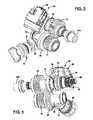
- FIG. 2is a schematic illustration of a single-speed power take-off unit associated with the disconnectable all-wheel drive system of FIG. 1 ;
- FIG. 3 through FIG. 5are perspective views of a single-speed power take-off unit based on the schematic shown in FIG. 2 with its housing structure removed for improved clarity and which is constructed in accordance with the present teachings;
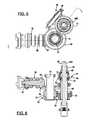
- FIG. 6is a sectional view of the single-speed power take-off unit taken generally along line 6 - 6 of FIG. 5 ;
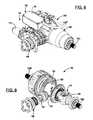
- FIG. 7is a schematic illustration of a single-speed rear drive module associated with the disconnectable all-wheel drive system of FIG. 1 ;
- FIGS. 8 through 10are perspective views of a single-speed rear drive module based on the schematic shown in FIG. 7 , with and without its housing structure, and which is constructed in accordance with the present teachings;
- FIG. 11is a sectional view of the single-speed rear drive module taken generally along line 11 - 11 of FIG. 10 ;
- FIG. 12is a schematic of a motor vehicle equipped with another configuration of a disconnectable all-wheel drive system constructed in accordance with the present teachings
- FIG. 13is a schematic illustration of a two-speed power take-off unit associated with the disconnectable all-wheel drive system of FIG. 12 ;
- FIG. 14is an exploded perspective view of a two-speed power take-off unit based on the schematic shown in FIG. 13 and which is constructed in accordance with the present teachings;
- FIG. 15is a sectional view of the two-speed power take-off unit shown in FIG. 14 ;
- FIGS. 16A through 16Dare partial sectional views of the two-speed power take-off unit shown in FIG. 15 with its mode and range shift components positioned to define a two-wheel high-range (2-Hi) mode, a four-wheel high-range (4-Hi) mode, a neutral mode, and a four-wheel low-range (4-Low) mode, respectively;
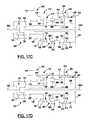
- FIGS. 17A through 17Dare schematic illustrations of a two-speed rear drive module associated with the disconnectable all-wheel drive system of FIG. 12 with its range shift components positioned to define a high-range (H) mode, a neutral (N) mode, a low-range (L) mode, and a low-range locked (LOCK) mode, respectively;
- Hhigh-range
- Nneutral
- Llow-range
- LOCKlow-range locked
- FIGS. 18 through 21are perspective views of a two-speed rear drive module based on the schematics shown in FIGS. 17 a through 17 d , with and without its housing structure, and which is constructed in accordance with the present teachings;
- FIG. 22is a sectional view taken generally along line 22 - 22 of FIG. 21 ;
- FIG. 23is a partial sectional view of an alternative exemplary embodiment of a two-speed rear drive module configured for use with the disconnectable all-wheel drive system of FIG. 12 .
- the vehicle 10can include a powertrain 12 and a drivetrain 14 that can include a primary driveline 16 , a power switching mechanism 18 , a secondary driveline 20 , and a control system 22 .
- the primary driveline 16can be a front driveline while the secondary driveline 20 can be a rear driveline.
- the powertrain 12can include a prime mover 24 , such as an internal combustion engine or an electric motor, and a transmission 26 which can be any type of ratio-changing mechanism, such as a manual, automatic, or continuously variable transmission.
- the prime mover 24is operable to provide rotary power to the primary driveline 16 and the power transfer mechanism 18 .
- the primary driveline 16can include a primary or first differential 30 having an input member 32 driven by an output member (not shown) of the transmission 26 .
- the first differential 30is configured as part of the transmission 26 , a type commonly referred to as a transaxle and typically used in front-wheel drive vehicles.
- the primary driveline 16can further include a pair of first axleshafts 34 L, 34 R that can couple output components of the first differential 30 to a set of first vehicle wheels 36 L, 36 R.
- the first differential 30can include a first differential case 38 that is rotatably driven by the input member 32 , at least one pair of first pinion gears 40 rotatably driven by the first differential case 38 , and a pair of first side gears 42 meshed with the first pinion gears 40 and which are connected to drive the first axleshafts 34 L, 34 R.
- the power switching mechanism 18can generally include a housing 46 , an input 48 coupled for common rotation with the first differential case 38 of the first differential 30 , an output 50 , a transfer gear assembly 52 , a disconnect mechanism 54 , and a disconnect actuator 56 .
- the input 48can include a tubular input shaft 58 rotatably supported by the housing 46 and which concentrically surrounds a portion of the first axleshaft 34 R. A first end of the input shaft 58 can be coupled for rotation with the first differential case 38 .
- the output 50can include an output pinion shaft 60 rotatably supported by the housing 46 and having a pinion gear 62 .
- the transfer gear assembly 52can include a hollow transfer shaft 64 , a helical gearset 66 , and a hypoid gear 68 that is meshed with the pinion gear 62 .
- the transfer shaft 64concentrically surrounds a portion of the first axleshaft 34 R and is rotatably supported by the housing 46 .
- the helical gearset 66can include a first helical gear 70 fixed for rotation with the transfer shaft 64 and a second helical gear 72 which is meshed with the first helical gear 70 .
- the second helical gear 72 and the hypoid gear 68are integrally formed on, or fixed for common rotation with, a stub shaft 74 that is rotatably supported in the housing 46 .
- the disconnect mechanism 54can comprise any type of clutch, disconnect or coupling device that can be employed to selectively transmit rotary power from the powertrain 14 to the secondary driveline 20 .
- the disconnect mechanism 54is configured as a dog clutch.
- the dog clutchcan include a set of external spline teeth 76 formed on a second end of the input shaft 58 , a set of external clutch teeth 78 formed on the transfer shaft 64 , a mode collar 80 having internal spline teeth 82 constantly meshed with the external spline teeth 76 on the input shaft 58 , and a shift fork 84 operable to axially translate the shift collar 80 between a first mode position and a second mode position. While schematically shown as a non-synchronized dog clutch, it will be understood that the disconnect mechanism 54 can include a synchronized dog clutch if such a configuration is desired.
- the mode collar 80is shown in its first mode position, identified by a “2WD” leadline, wherein the internal spline teeth 82 on the mode collar 80 are disengaged from the external clutch teeth 78 on the transfer shaft 64 .
- the input shaft 58is disconnected from driven engagement with the transfer shaft 64 .
- no rotary poweris transmitted from the powertrain 12 to the transfer gear assembly 52 and the output pinion shaft 60 of the power take-off unit 18 .
- the mode collar 80With the mode collar 80 in its second mode position, identified by an “AWD” leadline, its internal spline teeth 82 are engaged with both the external spline teeth 76 on the input shaft 58 and the external clutch teeth 78 on the transfer shaft 64 .
- the mode collar 80establishes a drive connection between the input shaft 58 and the transfer shaft 64 such that rotary power from the powertrain 12 is transmitted through the power take-off unit 18 to the output pinion shaft 60 .
- the output pinion shaft 60is coupled via a propshaft 86 to the secondary driveline 20 .
- the disconnect actuator 56can be any type of actuator mechanism that is operable for axially moving the shift fork 84 which, in turn, causes concurrent axial translation of the mode collar 80 between its two distinct mode positions.
- the disconnect actuator 56is shown mounted to the housing 46 of the power take-off unit 18 .
- the disconnect actuator 56can be a power-operated mechanism that can receive control signals from the control system 22 and can include, for example, hydraulically-actuated, pneumatically-actuated or electromechanically-actuated arrangements.
- FIG. 2schematically illustrates the components that can be associated with the power take-off unit 18 .
- Reference now to FIG. 3 through 6will provide a more definitive structural configuration of such components that are associated with an exemplary embodiment of the power take-off unit 18 .
- these figuresillustrate the components in an assembled condition with the housing 46 removed for improved clarity.
- Each of the input shaft 58 , the transfer shaft 64 , the stub shaft 74 , and the output pinion shaft 60are shown with suitable bearings assembled thereon for rotatably supporting each within or from the housing 46 .
- the disconnect actuator 56is shown as a self-contained power-operated unit 88 from which the shift fork 84 extends.
- the power-operated unit 88can include an electric motor and a geared drive unit configured to convert rotation of the motor output into translational movement of the shift fork 84 .
- External spline teeth 90are provided on one end of the first axleshaft 34 R for facilitating a splined connection with its respective first side gear 42 in the first differential 30 .
- external spline teeth 92are provided on the first end of the input shaft 58 for facilitating a splined connection with a mating portion of the first differential case 38 .
- the secondary driveline 20can include the propshaft 86 , a rear drive module (RDM) 100 , a pair of second axleshafts 102 L, 102 R, and a set of second vehicle wheels 104 L, 104 R.
- a first end of the propshaft 86can be coupled for rotation with the output pinion shaft 60 extending from the power take-off unit 18 while a second end of the propshaft 86 can be coupled for rotation with an input 106 of the rear drive module 100 .
- the rear drive module 100can include a housing 108 , a secondary or second differential 110 , a torque transfer device (TTD) 112 that is generally configured and arranged to selectively couple and transmit rotary power from the input 106 to the second differential 110 , and a TTD actuator 114 .
- the input 106can include an input pinion shaft 116 having a pinion gear 118 , a hollow spool 120 , and a hypoid gear 122 fixed for rotation with the spool 120 and which is meshed with the pinion gear 118 .
- the second differential 110can include a second differential case 124 , at least one pair of second pinion gears 126 rotatably driven by the second differential case 124 , and a pair of second output side gears 128 that are meshed with the second pinion gears 126 .
- the second output side gears 128are fixed for rotation with the inboard ends of the second axleshafts 102 L, 102 R.
- the torque transfer device 112can include any type of clutch or coupling device that can be employed to selectively transmit rotary power from the input 106 to the second differential 110 .
- the torque transfer device 112is a multi-plate friction clutch that can include an input clutch member 130 driven by the spool 120 , an output clutch member 132 coupled for rotation with the second differential case 124 , a multi-plate clutch pack 134 having interleaved friction plates disposed between the input and output clutch members, and an engagement member 136 that is moveable for selectively applying a clutch engagement force to the clutch pack 134 .
- An elongated hollow clutch output shaft 138can connect the output clutch member 132 for common rotation with the second differential case 124 and is configured to surround a portion of the second axleshaft 102 R.
- the TTD actuator 114is provided to generate translational movement of the engagement member 136 relative to the clutch pack 134 and can be controlled by control signals from the control system 22 .
- a first or “disconnected” modecan be established for the torque transfer device 112 when the engagement member 136 is positioned such that rotary power is not transmitted from the input clutch member 130 to the output clutch member 132 .
- this “disconnected” modethe second vehicle wheels 104 L, 104 R, the second axleshafts 102 L, 102 R, the second differential 110 , the clutch output shaft 138 and the output clutch member 132 are disconnected from the input 106 of the rear drive module 100 .
- rotation of these components as a result of rolling motion of the second vehicle wheelsdoes not “back-drive” the propshaft 86 and components of the power take-off unit 18 .
- a second or “connected” mode for the torque transfer device 112can be established when the clutch engagement force exerted by the engagement member 136 on the clutch pack 134 causes rotary power to be transmitted from the input 106 to the clutch output shaft 138 for delivery to the rear wheels 104 L, 104 R through the second differential 110 .
- a “torque biasing” functioncan also be provided in the connected mode since variable control over the magnitude of the clutch engagement force applied to the clutch pack 134 can vary the distribution ratio of the rotary power transmitted from the powertrain 12 to the primary driveline 16 and the secondary driveline 20 .
- the torque transfer device 112can be configured or controlled to slip or cyclically engage and disengage as appropriate for biasing the available drive torque while establishing the drive connection between the input 106 and the second differential 110 .
- the TTD actuator 114can be any power-operated device capable of shifting the torque transfer device 112 between its first and second modes as well as adaptively regulating the magnitude of the clutch engagement force exerted by the engagement member 136 on the clutch pack 134 .
- the TTD actuator 114can, for example, include an electromagnetic or motor-driven ballscrew, ballramp or other cam actuation system having a mechanical connection, shown by lead line 140 , with the engagement member 136 .
- the TTD actuator 114can include a hydraulic actuation system capable of regulating the position of the engagement member 136 relative to the clutch pack 134 by regulating fluid pressure, also indicated by lead line 140 , delivered to a pressure chamber.
- the control system 22is schematically shown in FIG. 1 to include a controller 150 , a group of first sensors 152 , and a group of second sensors 154 .
- the group of first sensors 152can be arranged within the motor vehicle 10 to sense a vehicle parameter and responsively generate a first sensor signal.
- the vehicle parametercan be associated with any combination of the following: vehicle speed, yaw rate, steering angle, engine torque, wheel speeds, shaft speeds, lateral acceleration, longitudinal acceleration, throttle position and gear position without limitations thereto.
- the group of second sensors 154can be configured to sense a driver-initiated input to one or more on-board devices and/or systems within the vehicle 10 and responsively generate a second sensor signal.
- the motor vehicle 10may be equipped with a sensor associated with a mode selection device, such as a switch associated with a push button or a lever, that senses when the vehicle operator has selected between vehicle operation in a two-wheel drive (FWD) mode and an all-wheel drive (AWD) mode.
- a mode selection devicesuch as a switch associated with a push button or a lever
- switched actuation of vehicular systemssuch as the windshield wipers, the defroster, and/or the heating system, for example, may be used by the controller 150 to assess whether the motor vehicle 10 should be shifted automatically between the FWD and AWD modes.
- FIG. 7schematically illustrates the components that can be associated with the rear drive module 100 .
- FIGS. 8 through 11a more definitive structural configuration of such components associated with an exemplary embodiment of the rear drive module 100 is shown. These views illustrate the components in an assembled condition, with and without the housing 108 .
- Each of the input pinion shaft 116 , the second axleshafts 102 L and 102 R, the second differential case 124 , the spool 120 and the clutch output shaft 138are shown with suitable bearings assembled thereon for rotatably supporting each within or from the housing 108 .
- FIG. 8 through 11a more definitive structural configuration of such components associated with an exemplary embodiment of the rear drive module 100 is shown. These views illustrate the components in an assembled condition, with and without the housing 108 .
- Each of the input pinion shaft 116 , the second axleshafts 102 L and 102 R, the second differential case 124 , the spool 120 and the clutch output shaft 138are shown with suitable bearings assembled thereon for rotat
- the engagement member 136can be an apply piston disposed in the pressure chamber which is supplied with pressurized hydraulic fluid by a hydraulically-operated unit 169 associated with the TTD actuator 114 .
- the hydraulically-operated unit 169can include a motor-driven fluid pump 170 , an accumulator 172 and related hydraulic components, all of which are disposed in close proximity to or attached to the housing 108 .
- the vehicle 10can normally be operated in the two-wheel drive (FWD) mode in which the power take-off unit 18 and the rear drive module 100 are both disengaged.
- the mode collar 80 of the disconnect mechanism 54is positioned by the disconnect actuator 56 in its first (2WD) mode position such that the input shaft 58 is uncoupled from the transfer shaft 64 .
- substantially all power provided by the powertrain 12is transmitted to the primary driveline 16 .
- the torque transfer device 112can be shifted into and maintained in its first (disconnected) mode such that the input 106 , the propshaft 86 , the output pinion shaft 60 and the transfer gear assembly 52 within the power take-off unit 18 are not back-driven due to rolling movement of the second vehicle wheels 104 .
- the control system 22can be activated via a suitable input which, as noted, can include a drive requested input (via the mode select device) and/or an input generated by the controller 150 in response to signals from the first sensors 152 and/or the second sensors 154 .
- the controller 150initially signals the TTD actuator 114 to shift the torque transfer device 112 into its second (connected) mode. Specifically, the controller 150 controls operation of the TTD actuator 114 such that the actuation member 136 is moved and a clutch engagement force is exerted on the clutch pack 134 that is sufficient to synchronize the speed of the secondary driveline 20 with the speed of the primary driveline 16 .
- the controller 150Upon speed synchronization, the controller 150 signals the actuator 56 to cause the mode collar 80 in the power take-off unit 18 to move from its first mode position into its second mode position. With the mode collar 80 in its second mode position, rotary power is transmitted from the powertrain 12 to the primary driveline 16 and the secondary driveline 20 . It will be appreciated that subsequent control of the magnitude of the clutch engagement force generated by the torque transfer device 112 permits torque biasing across the clutch pack 134 for controlling the torque distribution ratio transmitted from the powertrain 12 to the primary driveline 16 and the secondary driveline 20 .
- FIG. 12another motor vehicle constructed in accordance with the present teachings is generally indicated by reference numeral 10 ′.
- the vehicle 10 ′is generally similar to the vehicle 10 of FIG. 1 except that the primary driveline 16 ′ and the secondary driveline 20 ′ have been modified to incorporate a two-speed range unit into both the power take-off unit 18 ′ and the rear drive module 100 ′.
- this alternative drivetrain arrangement for the vehicle 10 ′permits establishment of at least one all-wheel low range drive mode in addition to the two-wheel high-range drive mode and the all-wheel high-range drive mode associated with vehicle 10 .
- primed reference numeralare used to designate components that are generally similar in structure and/or function to the non-primed components previously described in relation to FIGS. 1 through 11 .
- the power take-off unit 18 ′is generally shown to include a housing 46 ′, an input 48 ′ adapted for connection to an output member of the transmission 26 ′, an output 50 ′, a transfer gear assembly 52 ′, a first differential 30 ′, a disconnect mechanism 54 ′, a two-speed range unit 198 , and a disconnect actuator 56 ′.
- the input 48 ′can include a hollow input shaft 204 rotatably supported by the housing 46 ′ and surrounding the axleshaft 34 L′.
- the output 50 ′can include an output pinion shaft 60 ′ having a pinion gear 62 ′.
- the transfer gear assembly 52 ′can include a hollow transfer shaft 64 ′, a helical gearset 66 ′, and a hypoid gear 68 ′ meshed with the pinion gear 62 ′.
- the helical gearset 66 ′can include a first helical gear 70 ′ fixed for rotation with the transfer shaft 64 ′ and a second helical gear 72 ′ that is meshed with the first helical gear 70 ′.
- the second helical gear 72 ′ and the hypoid gear 68 ′are integral with or fixed to a stub shaft 74 ′ that is rotatably supported by the housing 46 ′.
- the two-speed range unit 198can include a planetary gear assembly 200 and a range shift mechanism 202 .
- the planetary gear assembly 200can include a ring gear 206 non-rotatably fixed to the housing 46 ′, a sun gear 208 , a plurality of planet gears 210 meshed with both the ring gear 206 and the sun gear 208 , and a planet carrier 212 from which the planet gears 210 are rotatably supported.
- the planet carrier 212is fixed to, or integrally formed with, the first differential case 38 ′ of the first differential 30 ′ for common rotation therewith.
- the range shift mechanism 202can include a sun gear shaft 220 surrounding a portion of the first axleshaft 34 L′ and which is fixed for rotation with the sun gear 208 , a carrier shaft 222 surrounding a portion of the sun gear shaft 220 and which is fixed for rotation with the planet carrier 212 , and a tubular range sleeve 224 surrounding portions of the carrier shaft 222 , the sun gear shaft 220 and the input shaft 204 .
- the input shaft 204can have a first end 226 adapted for connection via a splined coupling shaft 227 ( FIG. 14 ) to the output of transmission 26 ′ and a second end having a set of elongated external spline teeth 228 formed thereon.
- the range sleeve 224can include a set of internal spline teeth 230 that are in continuous meshed engagement with the external spline teeth 228 on the input shaft 204 . As such, the range sleeve 224 is coupled for common rotation with the input shaft 204 while being capable of bi-directional axial sliding movement thereon between a plurality of predefined range position which will be discussed hereinafter in greater detail.
- the range sleeve 224further defines a set of internal clutch teeth 232 that can be moved into and out of engagement with a set of external clutch teeth 234 formed on the carrier shaft 222 or a set of external clutch teeth 236 formed on the sun gear shaft 220 .
- the disconnect mechanism 54 ′is generally similar in function to the disconnect mechanism 54 in that it is configured to selectively connect the input shaft 204 to the transfer gear assembly 52 ′ for transmitting rotary power from the input shaft 204 to the output pinion shaft 60 ′ when the all-wheel drive mode is desired.
- the disconnect mechanism 54 ′differs in that the drive connection between the input shaft 204 and the transfer shaft 64 ′ is made indirectly via the range sleeve 224 .
- the range sleeve 224can include first and second sets of external spline teeth 240 and 242 , respectively, which are selectably engageable with internal spline teeth 244 formed on a mode collar 246 .
- the mode collar 246can be coupled for rotation with the range sleeve 224 and is capable of bi-directional axial translation relative to the range sleeve 224 between a first (2WD) mode position and a second (AWD) mode position.
- a set of internal clutch teeth 248 formed on the mode collar 246are released from meshed engagement with the external clutch teeth 78 ′ on the transfer shaft 64 ′, whereby no rotary power is transmitted from the input shaft 204 through the transfer gear assembly 52 ′ to the output pinion shaft 60 ′.
- its internal spline teeth 244are engaged with one of the first and second sets of external splines 240 and 242 (depending on the axial position of the range sleeve 224 ) and its internal clutch teeth 248 are engaged with the clutch teeth 78 ′ on the transfer shaft 64 ′, thereby establishing a drive connection between the input shaft 204 and the output pinion shaft 60 ′.
- the two-speed range unit 198is operable to establish at least two different speed ratio drive connections between the input shaft 204 and the first differential 30 ′.
- the range sleeve 224can be axially translated between a plurality of predefined range positions. In a first or “high” (Hi) range position, the range sleeve 224 is located such that its internal clutch teeth 232 are engaged with the external clutch teeth 234 on the carrier shaft 222 .
- the range sleeve 224is disconnected from driven connection with both of the carrier shaft 222 and the sun gear shaft 220 such that the input shaft 204 is disconnect from the first differential 30 ′.
- the range sleeve 224In a third or “low” (Low) range position, the range sleeve 224 is located such that its internal clutch teeth 232 are engaged with the external clutch teeth 236 formed on the sun gear shaft 220 . With the range sleeve 224 located in its low-range position, a second or reduced-ratio drive connection is established between the input shaft 204 and the first differential 30 ′. Specifically, driven rotation of the sun gear shaft 220 causes the planetary gear assembly 200 to drive the carrier 212 at a reduced speed relative to the input shaft 204 such that the primary driveline 16 ′ is likewise driven at the reduced speed ratio via the first differential 30 ′.
- the disconnect actuator 56 ′is shown positioned adjacent to the housing 46 ′ and can include a first shift fork 84 ′ engaging the mode collar 246 , a second shift fork 250 engaging the range sleeve 224 , and a power-operated unit 252 configured to receive control signals from the controller 150 and operable to coordinate movement of the shift forks 84 ′ and 250 .
- the power-operated unit 252can be any type of unit capable of selectively translating the first shift fork 84 ′ for causing movement of the mode collar 246 between its two mode positions while also selectively translating the second shift fork 250 for causing movement of the range sleeve 224 between its three range positions.
- FIG. 14illustrates an exploded perspective view of an exemplary embodiment of the two-speed power take-off unit 18 ′.
- Housing 46 ′is shown to include a multi-piece assembly having a main housing 258 to which a differential housing 260 and a PTU housing 262 are secured.
- FIG. 15is a sectional view which illustrates the compact arrangement of the planetary gear assembly 200 , the range shift mechanism 202 , the transfer gear assembly 52 ′, and the moveable mode collar 246 and range sleeve 224 .
- the bi-directional translational movement of the range sleeve 224 and the mode collar 246can be coordinated to establish a plurality of mode and range combinations for the two-speed power take-off unit 18 ′ based on control signals from the controller 150 .
- FIGS. 16A through 16Dthese various mode and range combinations can be more clearly illustrated.
- FIG. 16Ashows the positions of the range sleeve 224 and the mode collar 246 for establishing a two-wheel high-range (2-Hi) mode.
- the mode collar 246is shown located in its first mode position while the range sleeve 224 is located in its first range position.
- the input shaft 204is coupled via the range sleeve 224 to the carrier shaft 222 for establishing the direct drive connection between the powertrain 12 and the primary driveline 16 ′.
- the transfer shaft 64 ′is disconnected from driven connection with the input shaft 204 , thereby disconnecting the secondary driveline 20 ′ from the powertrain 12 .
- rotary poweris only transmitted by the powertrain 12 to the primary driveline 16 ′ without speed reduction.
- FIG. 16Bshows the positions of the range sleeve 224 and the mode collar 246 for establishing a four-wheel high-range (4-Hi) mode.
- the high-range connectionis maintained by the range sleeve 224 remaining in its first range position while the mode collar 246 is shown moved into its second mode position.
- the mode collar 246establishes a drive connection from the input shaft 204 (through the range sleeve 224 ) to the transfer shaft 64 ′ for also transmitting rotary power from the powertrain 12 to the secondary driveline 20 ′ without speed reduction.
- FIG. 16Cshows the positions of the range sleeve 224 and the mode collar 246 for establishing a Neutral non-driven mode.
- the mode collar 246is maintained in its second mode position while the range sleeve 224 has been axially moved into its second range position such that its internal splines 232 are disengaged from the external clutch teeth 234 on the carrier shaft 220 and the external clutch teeth 236 on the sun gear shaft 220 .
- the input shaft 204is disconnected from both inputs to the primary driveline 16 ′ such that no rotary power is transmitted from the powertrain 12 to the primary driveline 16 ′.
- FIG. 16Dshows the position of the mode collar 246 and the range sleeve 224 for establishing a four-wheel low-range (4-Low) mode.
- the mode collar 246is maintained in its second mode position while the range sleeve 224 is moved axially into its third range position.
- the low-range drive connectionis established by the range sleeve 224 between the input shaft 204 and the sun gear shaft 220 while the AWD connection is established by the mode collar 246 .
- the internal spline teeth 244 of the mode collar 246engage the second set of external spline teeth 242 upon movement of the range sleeve 224 from its neutral range position into its low range position.
- the secondary driveline 16 ′can include the propshaft 86 , a two-speed rear drive module 10 ′, a pair of second axleshafts 102 L′ and 102 R′, and the set of second vehicle wheels 104 L and 104 R.
- a first end of the propshaft 86is coupled to the output pinion shaft 60 ′ extending from the two-speed power take-off unit 18 ′ while a second end of the propshaft 86 is coupled for rotation with an input 106 ′ of the two-speed rear drive module 100 ′.
- the rear drive module 100 ′can include a housing 108 ′, a second differential 110 ′, a torque transfer device 112 ′ generally configured and arranged to selectively couple and transmit rotary power from the input 106 ′ to the second differential 110 ′, a TTD actuator 114 ′ for controlling actuation of the torque transfer device 112 ′, a two-speed range unit 278 having a planetary gear assembly 280 and a range shift mechanism 282 , and a range actuator 284 .
- the input 106 ′can include an input pinion shaft 116 ′ having a pinion gear 118 ′, a hollow spool 120 ′, and a hypoid gear 122 ′ fixed to the spool 120 ′ and which is meshed with the pinion gear 118 ′.
- the second differential 110 ′includes a second differential case 124 ′, at least one pair of second pinion gears 126 ′ rotatably supported by the second differential case 124 ′, and a pair of second output side gears 128 ′ that are meshed with the second pinion gears 126 ′.
- the second output side gears 128 ′are fixed for rotation with the inboard ends of the second axleshafts 102 L′ and 102 R′.
- Torque transfer device 112 ′is generally similar to torque transfer device 112 and can include an input clutch member 130 ′, an output clutch member 132 ′, a clutch pack 134 ′, and an engagement member 136 ′ that is moveable under the control of the TTD actuator 114 ′ based on control signals from the controller 150 .
- the output clutch member 132 ′can be a clutch drum 162 ′ that is coupled for rotation with a clutch output shaft 286 . Thus, torque transferred from the input 106 ′ through the torque transfer device 112 ′ is transmitted to the clutch output shaft 286 .
- the two-speed range unit 278is operable to establish at least two different speed ratio drive connections between the output clutch member 132 ′ and the second differential 110 ′.
- the planetary gear assembly 280can include a sun gear 290 fixed for rotation with the clutch output shaft 286 , a ring gear 292 non-rotatably fixed to the housing 108 ′, a plurality of planet gears 294 meshed with the sun gear 290 and the ring gear 292 , and a planet carrier 296 from which the planet gears 294 are rotatably supported.
- the range shift mechanism 282can include a first or direct clutch ring 300 fixed for rotation with the clutch output shat 286 , a second or low clutch ring 302 fixed for rotation with the planet carrier 296 , a third or drive clutch ring 304 fixed for rotation with a differential input shaft 306 , a fourth or lock clutch ring 308 fixed for rotation with the second axleshaft 102 R′, and a range sleeve 310 .
- the differential input shaft 306can surround the second axleshaft 102 R′ and is connected for rotation with the second differential case 124 ′ of the second differential 110 ′.
- the range sleeve 310can include a set of internal spline teeth 312 that are in continuous meshed engagement with a set of external spline teeth 314 formed on the drive clutch ring 304 . As such, the range sleeve 310 is coupled for common rotation with the drive clutch ring 304 while being capable of bi-directional axial sliding movement thereon.
- the range sleeve 310further includes a set of internal clutch teeth 316 .
- translational movement of the range sleeve 310is operable to establish the two different speed range drive connections between the output shaft 286 of the torque transfer device 112 ′ and the second differential case 124 ′ of the second differential 110 ′.
- the range sleeve 310is shown in FIG. 17A positioned in a first or high range position such that its internal spline teeth 312 are meshed with both the external spline teeth 314 on the drive clutch ring 304 and with a set of external spline teeth 318 formed on the direct clutch ring 300 . It will also be seen that the clutch teeth 316 on the range sleeve 310 are disengaged from meshed engagement with a set of external clutch teeth 320 formed on the low clutch ring 302 .
- a first or direct ratio drive connectionis established between the output clutch member 132 ′ and the second differential case 124 ′ of the second differential 110 ′ via the clutch output shaft 286 , the range sleeve 310 and the differential input shaft 306 .
- the range sleeve 310is shown in FIG. 17B positioned in a second or neutral position such that its internal teeth 312 remain engaged only with the external teeth 314 on the drive clutch ring 304 while its internal clutch teeth 316 remain disengaged from the external clutch teeth 320 on the low clutch ring 302 .
- the output clutch member 132 ′is released from driven connection with the second differential case 124 ′ of the second differential 110 ′.
- the range sleeve 310is shown in FIG. 17C positioned in a third or low range position such that its internal spline teeth 312 remain meshed with the external spline teeth 314 on the drive clutch ring 304 while its internal clutch teeth 316 are now meshed with the external clutch teeth 318 on the low clutch ring 302 .
- driven rotation of the sun gear 290causes the planet carrier 296 to rotate at a reduced speed to establish a second or reduced ratio drive connection between the output clutch member 132 ′ and the differential case 124 ′ via the carrier 296 , the low clutch ring 302 , the range sleeve 310 , the drive clutch ring 304 , and the second differential input shaft 306 .
- FIG. 17Dshows the range sleeve 310 positioned in a fourth or low locked position.
- the internal spline teeth 312 on the range sleeve 310are meshed with both the external spline teeth 314 on the drive clutch ring 304 and a set of external spline teeth 322 formed on the lock clutch ring 308 while the internal clutch teeth 316 on the range sleeve 310 remain engaged with the external clutch teeth 320 on the low clutch ring 302 .
- the reduced ratio drive connection of FIG. 17Cis maintained with the addition that the second differential 110 ′ is now locked since the second differential case 124 ′ and the second axleshaft 102 R are prevented from rotating relative to each other.
- the range actuator 284can be any type of power-operated mechanism that is operable to control axial translational movement of a range fork 324 which, in turn, causes movement of the range sleeve 310 between its four distinct range positions.
- the range actuator 284is shown mounted to housing 108 ′ of the two-speed rear drive module 100 ′.
- the range actuator 284is preferably a motor-driven geared device configured to receive control signals from the controller 150 to convert rotation of the motor output into translational movement of the range fork 324 .
- FIGS. 17A through 17Dschematically illustrate the components that can be associated with the two-speed rear drive module 100 ′.
- Reference now to FIGS. 18-22will provide a more definitive structural configuration of such components that are associated with an exemplary embodiment of the two-speed rear drive module 100 ′.
- a splined connection 330is provided to couple the clutch drum 162 ′ to a first end of the clutch output shaft 286 .
- the sun gear 290can be formed integrally with the clutch output shaft 286 .
- FIG. 23a partial sectional view of an alternative exemplary embodiment of the two-speed rear drive module 100 ′ is shown which incorporates a modified range shaft mechanism 282 ′.
- the range shift mechanism 282 ′is substantially similar to the range shift mechanism 282 shown in FIGS. 17A-22 with the exception that the low lock clutch ring 308 has been eliminated to thereby eliminate the low locked range mode shown in FIG. 17D .
- the range sleeve 310 ′may be slightly modified in construction but is still operable to establish the high-range, neutral, and low range drive connections between the clutch output shaft 286 and the differential input shaft 306 .
- the vehicle 10 ′can normally be operated in a two-wheel high-range drive mode in which the power take-off unit 18 ′ establishes a high-range drive connection between the powertrain 12 and the primary driveline 16 ′ while the rear drive module 100 ′ is disengaged.
- the range sleeve 224 and mode collar 246 respectively associated with the range shift mechanism 202 and the disconnect mechanism 54 ′are located as shown in FIG. 16A to establish the 2-Hi mode. With the mode collar 246 in its first mode position, the input shaft 204 is disconnected from the transfer shaft 64 ′ such that substantially all rotary power is transferred from the powertrain 12 to the primary driveline 16 ′.
- the torque transfer device 112 ′is maintained in its first (disconnected) mode to disconnect the secondary driveline 20 ′. While the torque transfer device 112 ′ is operating in its disconnected mode, the range sleeve 310 can be located in its high-range position ( FIG. 17A ).
- the control system 22can be activated to initially signal the TTD actuator 114 ′ to shift the torque transfer device 112 ′ into its second (connected) mode for synchronizing the speeds of the primary driveline 16 ′ and the secondary driveline 20 ′.
- the controller 150signals the actuator 56 ′ to shift the mode collar 246 to its second mode position while maintaining the range sleeve in its first range position ( FIG. 16B ). This establishes a four-wheel high-range drive connection between the powertrain 12 , the primary driveline 16 ′ and the input 106 ′ to the rear drive module 100 ′.
- the range actuator 284can be actuated to maintain or move the range sleeve 310 into its high-range position ( FIG. 17A ) such that rotary power delivered through the torque transfer device 112 ′ is transmitted to the second differential 110 ′ at the direct speed ratio. Thereafter, the TTD actuator 114 ′ can be controlled to vary the torque transmitted through the torque transfer device 112 ′ to the second vehicle wheels 104 L, 104 R with the second differential 110 ′ operating in an open state for permitting speed differentiation between the second vehicle wheels 104 L, 104 R.
- the control system 22functions to coordinate shifting of the power take-off unit 18 ′ into its four-wheel low-range mode and the rear drive module 100 ′ into its low-range mode. Specifically, the positions of the mode collar 246 and the range sleeve 224 of the power take-off unit 18 ′ to establish this connection are shown in FIG. 16D while the position of the range sleeve 310 of the rear drive module 100 ′ to establish this connection is shown in FIG. 17C .
- the low-range drive connectionsare established in the power take-off unit 18 ′ and the rear drive module 100 ′. These low-range drive connections can be established sequentially or concurrently based on a suitable control method and can be established with the vehicle 10 ′ in a stationary or non-motive state.
- the control system 22can request operation of the vehicle in an all-wheel drive low-lock range (AWD-LOCK) drive mode. This entails signaling the range actuator 284 to shift the range sleeve 310 into its low lock position ( FIG. 17D ) while maintaining the power take-off unit 18 ′ in its four-wheel low-range mode ( FIG. 16D ).
- AWD-LOCKall-wheel drive low-lock range
- a towing mode for the vehicle 10 ′can be established by shifting the power take-off unit 18 ′ into its neutral mode ( FIG. 16C ) and shifting the rear drive module 100 ′ into its neutral mode ( FIG. 17B ).
Landscapes
- Engineering & Computer Science (AREA)
- Mechanical Engineering (AREA)
- Chemical & Material Sciences (AREA)
- Combustion & Propulsion (AREA)
- Transportation (AREA)
- General Engineering & Computer Science (AREA)
- Arrangement And Driving Of Transmission Devices (AREA)
- Retarders (AREA)
- Arrangement And Mounting Of Devices That Control Transmission Of Motive Force (AREA)
Abstract
Description
Claims (20)
Priority Applications (13)
| Application Number | Priority Date | Filing Date | Title |
|---|---|---|---|
| US13/470,941US8795126B2 (en) | 2012-05-14 | 2012-05-14 | Disconnectable driveline for all-wheel drive vehicle |
| US13/785,425US8961353B2 (en) | 2012-05-14 | 2013-03-05 | Two-speed disconnecting driveline with one reduction gearset |
| US13/832,341US8784254B2 (en) | 2012-05-14 | 2013-03-15 | Power transmitting component |
| CN201710164896.0ACN106891718B (en) | 2012-05-14 | 2013-05-09 | Separable power train for all-wheel drive vehicles |
| PCT/US2013/040252WO2013173153A1 (en) | 2012-05-14 | 2013-05-09 | Disconnectable driveline for all-wheel drive vehicle |
| CN201710164856.6ACN106904073B (en) | 2012-05-14 | 2013-05-09 | Separable power train for all-wheel drive vehicle |
| BR112014028142-4ABR112014028142B1 (en) | 2012-05-14 | 2013-05-09 | TRANSMISSION TRAIN FOR A MOTORIZED VEHICLE WITH ALL-WHEEL DRIVE |
| DE112013002482.9TDE112013002482B4 (en) | 2012-05-14 | 2013-05-09 | Interruptible powertrain for a four-wheel drive vehicle |
| DE112013007819.8TDE112013007819B4 (en) | 2012-05-14 | 2013-05-09 | Interruptible drive train for a four-wheel drive vehicle |
| CN201380025386.5ACN104321213B (en) | 2012-05-14 | 2013-05-09 | Separable driveline for all-wheel drive vehicles |
| KR1020147034640AKR101906652B1 (en) | 2012-05-14 | 2013-05-09 | Disconnectable driveline for all-wheel drive vehicle |
| US14/244,158US9074672B2 (en) | 2012-05-14 | 2014-04-03 | Disconnectable driveline for all-wheel drive vehicle |
| US14/732,947US9511666B2 (en) | 2012-05-14 | 2015-06-08 | Disconnectable driveline for all-wheel drive vehicle |
Applications Claiming Priority (1)
| Application Number | Priority Date | Filing Date | Title |
|---|---|---|---|
| US13/470,941US8795126B2 (en) | 2012-05-14 | 2012-05-14 | Disconnectable driveline for all-wheel drive vehicle |
Related Child Applications (3)
| Application Number | Title | Priority Date | Filing Date |
|---|---|---|---|
| US13/785,425Continuation-In-PartUS8961353B2 (en) | 2012-05-14 | 2013-03-05 | Two-speed disconnecting driveline with one reduction gearset |
| US13/832,341Continuation-In-PartUS8784254B2 (en) | 2012-05-14 | 2013-03-15 | Power transmitting component |
| US14/244,158ContinuationUS9074672B2 (en) | 2012-05-14 | 2014-04-03 | Disconnectable driveline for all-wheel drive vehicle |
Publications (2)
| Publication Number | Publication Date |
|---|---|
| US20130303326A1 US20130303326A1 (en) | 2013-11-14 |
| US8795126B2true US8795126B2 (en) | 2014-08-05 |
Family
ID=49549040
Family Applications (3)
| Application Number | Title | Priority Date | Filing Date |
|---|---|---|---|
| US13/470,941Active2032-07-09US8795126B2 (en) | 2012-05-14 | 2012-05-14 | Disconnectable driveline for all-wheel drive vehicle |
| US14/244,158ActiveUS9074672B2 (en) | 2012-05-14 | 2014-04-03 | Disconnectable driveline for all-wheel drive vehicle |
| US14/732,947ActiveUS9511666B2 (en) | 2012-05-14 | 2015-06-08 | Disconnectable driveline for all-wheel drive vehicle |
Family Applications After (2)
| Application Number | Title | Priority Date | Filing Date |
|---|---|---|---|
| US14/244,158ActiveUS9074672B2 (en) | 2012-05-14 | 2014-04-03 | Disconnectable driveline for all-wheel drive vehicle |
| US14/732,947ActiveUS9511666B2 (en) | 2012-05-14 | 2015-06-08 | Disconnectable driveline for all-wheel drive vehicle |
Country Status (6)
| Country | Link |
|---|---|
| US (3) | US8795126B2 (en) |
| KR (1) | KR101906652B1 (en) |
| CN (3) | CN106891718B (en) |
| BR (1) | BR112014028142B1 (en) |
| DE (2) | DE112013002482B4 (en) |
| WO (1) | WO2013173153A1 (en) |
Cited By (14)
| Publication number | Priority date | Publication date | Assignee | Title |
|---|---|---|---|---|
| US20150057125A1 (en)* | 2013-08-23 | 2015-02-26 | American Axle & Manufacturing, Inc. | Power transmitting component with torque transfer device configured with drag reduction system |
| US20150141192A1 (en)* | 2013-08-23 | 2015-05-21 | American Axle & Manufacturing, Inc. | Clutched power transmitting device with filter element |
| US9302581B1 (en) | 2014-10-10 | 2016-04-05 | American Axle & Manufacturing, Inc. | All-wheel drive driveline with disconnecting axle |
| DE102015119067A1 (en) | 2014-11-18 | 2016-05-19 | E-Aam Driveline Systems Ab | Disconnect a powertrain for four-wheel drive with torque vectoring capabilities |
| US20160243936A1 (en)* | 2015-02-25 | 2016-08-25 | Toyota Jidosha Kabushiki Kaisha | Transfer |
| DE102016103739A1 (en) | 2015-03-04 | 2016-09-08 | American Axle & Manufacturing, Inc. | Actuator arrangement with a magnetic coupling |
| US20170015195A1 (en)* | 2014-03-25 | 2017-01-19 | Toyota Jidosha Kabushiki Kaisha | Transfer for four-wheel drive vehicle |
| US9732841B2 (en) | 2015-11-03 | 2017-08-15 | American Axle & Manufacturing, Inc. | Driveline component with mechanism to control lubricant level |
| DE102016217922A1 (en) | 2016-09-19 | 2018-03-22 | Zf Friedrichshafen Ag | automatic transmission |
| US10112481B2 (en) | 2015-04-28 | 2018-10-30 | Borgwarner Inc. | Power transfer unit (PTU) assembly with cylinder |
| US10124451B2 (en)* | 2014-10-17 | 2018-11-13 | American Axle & Manufacturing, Inc. | Driveline component having ring gear integrally formed with tubular drive member |
| US10267401B2 (en) | 2015-11-25 | 2019-04-23 | American Axle & Manufacturing, Inc. | Axle assembly |
| US10487889B2 (en) | 2016-03-25 | 2019-11-26 | American Axle & Manufacturing, Inc. | Disconnecting axle assembly |
| DE112016003291B4 (en)* | 2015-07-21 | 2021-06-10 | American Axle & Manufacturing, Inc. | Powertrain actuator powered by a synchronization event |
Families Citing this family (38)
| Publication number | Priority date | Publication date | Assignee | Title |
|---|---|---|---|---|
| US8961353B2 (en)* | 2012-05-14 | 2015-02-24 | American Axle & Manufacturing, Inc. | Two-speed disconnecting driveline with one reduction gearset |
| US8795126B2 (en) | 2012-05-14 | 2014-08-05 | American Axle & Manufacturing, Inc. | Disconnectable driveline for all-wheel drive vehicle |
| US9234571B2 (en)* | 2012-07-23 | 2016-01-12 | Honda Motor Co., Ltd. | Vehicular power transmission device |
| DE112013004889B4 (en) | 2012-10-05 | 2022-02-17 | American Axle & Manufacturing, Inc. | Separate one-speed and two-speed axle assemblies |
| US8857293B2 (en)* | 2013-03-11 | 2014-10-14 | American Axle & Manufacturing, Inc. | Power transmitting component with multi-part housing assembly having continuous sealing flange |
| US9062744B2 (en) | 2013-03-13 | 2015-06-23 | American Axle & Manufacturing, Inc. | Two-speed drive module |
| DE112014001879B4 (en)* | 2013-04-09 | 2024-02-22 | Magna powertrain gmbh & co kg | Method for controlling a temporarily all-wheel drive motor vehicle |
| US9016150B2 (en)* | 2013-07-29 | 2015-04-28 | Ford Global Technologies, Llc | Transmission having selectable power transfer shaft |
| US9303696B2 (en) | 2013-08-23 | 2016-04-05 | American Axle & Manufacturing, Inc. | Optimized outer clutch housing for reduced spin loss, improved oil flow and improved clutch durability |
| WO2016018203A1 (en)* | 2014-07-28 | 2016-02-04 | Gkn Driveline North America, Inc. | Vehicle final drive unit |
| US9752624B2 (en)* | 2014-10-22 | 2017-09-05 | Deere & Company | Tractor/implement PTO connection mechanism |
| CN107635816A (en)* | 2015-05-28 | 2018-01-26 | 博格华纳公司 | Disengaged using the power train of multimode clutch |
| US9902262B2 (en)* | 2015-11-19 | 2018-02-27 | American Axle & Manufacturing, Inc. | Power take-off unit with locking differential |
| US9895971B2 (en)* | 2015-11-20 | 2018-02-20 | American Axle & Manufacturing, Inc. | Disconnecting all-wheel drive driveline having flat tow capabilities |
| US9731597B2 (en)* | 2015-12-14 | 2017-08-15 | American Axle & Manufacturing, Inc. | Disconnectable driveline with brake system |
| CN108463354B (en) | 2016-01-26 | 2021-04-30 | 美国轮轴制造公司 | Disconnect axle assembly with planetary differential |
| DE102016202870B4 (en)* | 2016-02-24 | 2018-08-30 | Audi Ag | Transmission device for a motor vehicle |
| CN108698509B (en)* | 2016-03-01 | 2022-07-08 | 博格华纳公司 | Rotary Multi-Mode Clutch Module for All Wheel Drive Systems |
| JP2018016190A (en)* | 2016-07-27 | 2018-02-01 | 株式会社 神崎高級工機製作所 | Axle driving device |
| CN106314136B (en)* | 2016-08-31 | 2017-12-22 | 吉林大学 | An electric drive axle system based on a single planetary two-speed transmission and its control method |
| CN106195194B (en)* | 2016-08-31 | 2019-02-01 | 吉林大学 | A kind of electric drive axle system and its control method based on two-gear transmission |
| US10145461B2 (en) | 2017-02-01 | 2018-12-04 | American Axle & Manufacturing, Inc. | Disconnecting power take-off with input shaft having pressed-on seal journal |
| CN107415673A (en)* | 2017-07-27 | 2017-12-01 | 奇瑞汽车股份有限公司 | A kind of hybrid power system for automobile and application |
| JP6662368B2 (en)* | 2017-12-28 | 2020-03-11 | トヨタ自動車株式会社 | Control device for four-wheel drive vehicle |
| CN108189665A (en)* | 2018-02-11 | 2018-06-22 | 浙江华亦海汽车电子科技有限公司 | A kind of drive system of electric automobile configuration |
| KR102588934B1 (en)* | 2018-07-31 | 2023-10-16 | 현대자동차주식회사 | Powertrain for vehicle |
| KR102588935B1 (en)* | 2018-08-29 | 2023-10-16 | 현대자동차주식회사 | Powertrain for vehicle |
| CA3129053A1 (en)* | 2019-02-05 | 2020-08-13 | Linamar Corporation | Twin clutch two speed disconnect rdu |
| CN109958760B (en)* | 2019-03-07 | 2020-07-31 | 江苏大学 | An in-wheel motor-driven electric vehicle shifting device and shifting method based on a transmission mechanism |
| CN112032275B (en)* | 2019-06-03 | 2021-07-20 | 哈尔滨工业大学 | A mechanical four-axle differential device |
| US11293360B2 (en) | 2019-06-26 | 2022-04-05 | Team Industries, Inc. | Smart driveline disconnect |
| US11306803B2 (en)* | 2019-11-14 | 2022-04-19 | Gkn Automotive Limited | Vehicle drive unit assembly |
| CN112078360A (en)* | 2020-09-26 | 2020-12-15 | 郭佳 | Single-power-source dual-drive device and combination method |
| US11691506B2 (en)* | 2020-09-30 | 2023-07-04 | Gkn Automotive Limited | Shifting mechanism for a vehicle power transfer unit |
| WO2022104480A1 (en)* | 2020-11-23 | 2022-05-27 | Magna Powertrain, Inc. | Disconnecting differential mechanisms for motor vehicles |
| US12276323B2 (en)* | 2021-07-21 | 2025-04-15 | Dana Heavy Vehicle Systems Group, Llc | Transmission and method for operation of the transmission |
| WO2024010979A2 (en)* | 2022-07-08 | 2024-01-11 | Linamar Corporation | Two-speed disconnecting awd systems with pinion coupler |
| CN222811159U (en) | 2024-08-03 | 2025-04-29 | 东莞贺比嘉模型科技有限公司 | Remote control model car gearbox transmission breaking mechanism |
Citations (40)
| Publication number | Priority date | Publication date | Assignee | Title |
|---|---|---|---|---|
| US2783661A (en) | 1952-05-15 | 1957-03-05 | Gen Motors Corp | Two speed rear axle |
| US4407387A (en) | 1981-05-29 | 1983-10-04 | General Motors Corporation | Control system for split axle drive mechanism |
| US4774857A (en) | 1987-02-05 | 1988-10-04 | Dana Corporation | Two speed axle assembly |
| US4915190A (en) | 1988-01-13 | 1990-04-10 | Toyota Jidosha Kabushiki Kaisha | Control system for split axle drive mechanism in part-time four-wheel drive vehicle |
| US5105902A (en) | 1990-12-07 | 1992-04-21 | New Venture Gear, Inc. | Transfer case shift-on-fly system |
| US5105901A (en) | 1989-12-09 | 1992-04-21 | Mazda Motor Corporation | Four wheel drive system |
| US5411110A (en) | 1993-03-09 | 1995-05-02 | New Venture Gear, Inc. | Power transfer system for a four-wheel drive vehicle |
| US5562566A (en) | 1994-10-03 | 1996-10-08 | Yang; Tai-Her | Distributed differential mixing combined power system |
| US5599249A (en) | 1995-08-17 | 1997-02-04 | New Venture Gear, Inc. | Part-time double offset transfer case |
| KR19990020807U (en) | 1997-11-28 | 1999-06-25 | 정몽규 | Part-time four-wheel drive control unit |
| US5947858A (en)* | 1997-12-15 | 1999-09-07 | New Venture Gear, Inc. | Full-time transfer case with integrated planetary gear assembly and synchronized range shift mechanism |
| US5951428A (en) | 1996-12-12 | 1999-09-14 | Ntn Corporation | Rotation transmission device |
| KR100274035B1 (en) | 1997-12-31 | 2000-12-15 | 정몽규 | 4 wheels drive mechanism |
| US6186258B1 (en) | 1999-02-09 | 2001-02-13 | General Motors Corporation | Dynamic all wheel drive |
| KR100291087B1 (en) | 1997-12-09 | 2001-06-01 | 이계안 | Device and method for controlling automatic conversion travelling mode of part time 4 wheel driving vehicle |
| US6263995B1 (en) | 1992-06-24 | 2001-07-24 | Borg Warner Inc. | On demand vehicle drive system |
| US20020088291A1 (en) | 2001-01-10 | 2002-07-11 | Bowen Thomas C. | Twin clutch automated transmission with integrated transfer case |
| US20020137591A1 (en)* | 2001-03-23 | 2002-09-26 | Frost Barry L. | Three-speed transfer case |
| US6805653B2 (en) | 2002-08-02 | 2004-10-19 | Visteon Global Technologies, Inc. | Selectively controlled limited slip differential |
| US6814682B2 (en) | 2002-05-07 | 2004-11-09 | Borgwarner Inc. | Transfer case with synchronizer clutch |
| US20050023063A1 (en) | 2003-04-08 | 2005-02-03 | Mueller Joseph G. | On-demand transfer case |
| US6851501B2 (en)* | 2001-04-30 | 2005-02-08 | Gkn Driveline North America, Inc. | Full time all wheel drive system |
| KR100483163B1 (en) | 2003-04-03 | 2005-04-14 | 현대자동차주식회사 | Normal towing system of Full Time 4-Wheel Drive |
| US6974400B2 (en) | 2002-02-05 | 2005-12-13 | American Axle & Manufacturing, Inc. | Transfer case with a tri-mode bi-directional clutch assembly |
| US7081064B2 (en)* | 2003-10-30 | 2006-07-25 | Magna Powertrain Usa, Inc. | Two-speed transfer case with adaptive clutch control |
| US7150694B2 (en) | 2004-03-15 | 2006-12-19 | Magna Powertrain Usa, Inc. | Power take-off unit for four-wheel drive vehicle |
| US20060283654A1 (en) | 2005-06-02 | 2006-12-21 | Krisher James A | Transaxle unit with integrated power take-off unit and torque coupling device |
| US7331896B1 (en) | 2005-04-19 | 2008-02-19 | Dana Corporation | Torque control system for all-wheel drive drivetrain |
| US7416505B2 (en) | 2004-03-10 | 2008-08-26 | American Axle & Manufacturing, Inc. | Two-speed all-wheel drive system |
| US20080227582A1 (en) | 2007-03-16 | 2008-09-18 | Brent Michael Peura | Two-Stage Two-Speed Front Differential |
| US7533754B2 (en) | 2006-02-22 | 2009-05-19 | Ford Global Technologies, Llc | Hybrid motor vehicle driveline |
| US20100216593A1 (en) | 2006-08-02 | 2010-08-26 | Todd Ekonen | Two-Speed Power Take-Off Unit |
| WO2010104853A2 (en) | 2009-03-09 | 2010-09-16 | Magna Powertrain Of America, Inc. | All-wheel drive with active dry disconnect system |
| US8042642B2 (en) | 2008-08-14 | 2011-10-25 | American Axle & Manufacturing, Inc. | Motor vehicle with disconnectable all-wheel drive system |
| US8047323B2 (en) | 2008-08-14 | 2011-11-01 | American Axle & Manufacturing, Inc. | Motor vehicle with disconnectable all-wheel drive system |
| US20110275470A1 (en) | 2009-01-21 | 2011-11-10 | Magna Powertrain Of America, Inc. | Awd vehicle with disconnect system |
| US20120029779A1 (en) | 2010-07-30 | 2012-02-02 | Michael Thomas Dickinson | Control system and method for automatic control of selection of on-demand all-wheel drive assembly for a vehicle drivetrain |
| US20120073929A1 (en) | 2010-09-28 | 2012-03-29 | Ford Global Technologies, Llc | All Wheel Drive Speed Synchronization and Connection |
| US20120083380A1 (en) | 2010-07-23 | 2012-04-05 | Reed Richard G | Multi-mode drive system for transaxle applications |
| US8172712B2 (en) | 2007-05-29 | 2012-05-08 | Chrysler Group Llc | Compact power transfer unit for transaxle applications |
Family Cites Families (19)
| Publication number | Priority date | Publication date | Assignee | Title |
|---|---|---|---|---|
| IT1238112B (en)* | 1989-10-10 | 1993-07-07 | Fiat Auto Spa | TRANSMISSION WITH INTEGRAL TRACTION DISARMABLE FOR VEHICLES |
| US5916051A (en)* | 1997-03-21 | 1999-06-29 | New Venture Gear, Inc. | Hydraulic shift system for a transfer case |
| DE19748525B4 (en)* | 1997-11-03 | 2007-01-18 | Steyr-Daimler-Puch Fahrzeugtechnik Ag & Co. Kg | Four-wheel drive unit with central differential |
| US6579204B2 (en)* | 1999-03-09 | 2003-06-17 | New Venture Gear, Inc. | Synchronized two-speed transfer case with lockable limited slip differential |
| CN2429369Y (en)* | 2000-07-12 | 2001-05-09 | 谭仁专 | Four-wheels drives of car |
| US6626787B2 (en)* | 2001-04-02 | 2003-09-30 | New Venture Gear, Inc. | On-demand all-wheel drive system |
| US6575867B1 (en)* | 2001-12-21 | 2003-06-10 | New Venture Gear, Inc. | Three-speed transfer case |
| JP3582521B2 (en)* | 2002-08-13 | 2004-10-27 | 日産自動車株式会社 | Driving force control device for four-wheel drive vehicle |
| DE10315181B4 (en)* | 2003-04-03 | 2006-06-08 | Fzg Mbh | Drive arrangement for motor vehicles |
| JP4386171B2 (en)* | 2003-12-04 | 2009-12-16 | 三菱自動車工業株式会社 | Power transmission device for four-wheel drive vehicles |
| CN100562673C (en)* | 2005-01-26 | 2009-11-25 | 美国麦格纳传动系公司 | Power-operated clutch actuator for a torque-transmitting mechanism |
| DE102006022173A1 (en)* | 2006-05-12 | 2007-11-15 | Zf Friedrichshafen Ag | Transmission device for distributing a drive torque to at least two drive shafts |
| EP2137422B8 (en)* | 2007-03-19 | 2017-10-11 | Eaton Corporation | Idle-able power transfer unit |
| JP4313828B2 (en)* | 2007-05-31 | 2009-08-12 | 三菱自動車工業株式会社 | Left / right driving force distribution device |
| JP5265947B2 (en)* | 2008-03-13 | 2013-08-14 | 株式会社ユニバンス | Driving force transmission device for four-wheel drive vehicles |
| KR101250921B1 (en) | 2008-10-15 | 2013-04-04 | (주)엘지하우시스 | Tape |
| US8388486B2 (en)* | 2009-08-11 | 2013-03-05 | Magna Powertrain Of America, Inc. | AWD vehicle with active disconnect coupling having multi-stage ball ramp |
| US9371869B2 (en) | 2011-03-15 | 2016-06-21 | GKN Driveline Japan Ltd. | Power transmission apparatus |
| US8795126B2 (en)* | 2012-05-14 | 2014-08-05 | American Axle & Manufacturing, Inc. | Disconnectable driveline for all-wheel drive vehicle |
- 2012
- 2012-05-14USUS13/470,941patent/US8795126B2/enactiveActive
- 2013
- 2013-05-09DEDE112013002482.9Tpatent/DE112013002482B4/ennot_activeExpired - Fee Related
- 2013-05-09CNCN201710164896.0Apatent/CN106891718B/enactiveActive
- 2013-05-09DEDE112013007819.8Tpatent/DE112013007819B4/ennot_activeExpired - Fee Related
- 2013-05-09WOPCT/US2013/040252patent/WO2013173153A1/enactiveApplication Filing
- 2013-05-09KRKR1020147034640Apatent/KR101906652B1/enactiveActive
- 2013-05-09BRBR112014028142-4Apatent/BR112014028142B1/enactiveIP Right Grant
- 2013-05-09CNCN201710164856.6Apatent/CN106904073B/enactiveActive
- 2013-05-09CNCN201380025386.5Apatent/CN104321213B/enactiveActive
- 2014
- 2014-04-03USUS14/244,158patent/US9074672B2/enactiveActive
- 2015
- 2015-06-08USUS14/732,947patent/US9511666B2/enactiveActive
Patent Citations (42)
| Publication number | Priority date | Publication date | Assignee | Title |
|---|---|---|---|---|
| US2783661A (en) | 1952-05-15 | 1957-03-05 | Gen Motors Corp | Two speed rear axle |
| US4407387A (en) | 1981-05-29 | 1983-10-04 | General Motors Corporation | Control system for split axle drive mechanism |
| US4774857A (en) | 1987-02-05 | 1988-10-04 | Dana Corporation | Two speed axle assembly |
| US4915190A (en) | 1988-01-13 | 1990-04-10 | Toyota Jidosha Kabushiki Kaisha | Control system for split axle drive mechanism in part-time four-wheel drive vehicle |
| US5105901A (en) | 1989-12-09 | 1992-04-21 | Mazda Motor Corporation | Four wheel drive system |
| US5105902A (en) | 1990-12-07 | 1992-04-21 | New Venture Gear, Inc. | Transfer case shift-on-fly system |
| US6263995B1 (en) | 1992-06-24 | 2001-07-24 | Borg Warner Inc. | On demand vehicle drive system |
| US5411110A (en) | 1993-03-09 | 1995-05-02 | New Venture Gear, Inc. | Power transfer system for a four-wheel drive vehicle |
| US5562566A (en) | 1994-10-03 | 1996-10-08 | Yang; Tai-Her | Distributed differential mixing combined power system |
| US5599249A (en) | 1995-08-17 | 1997-02-04 | New Venture Gear, Inc. | Part-time double offset transfer case |
| US5951428A (en) | 1996-12-12 | 1999-09-14 | Ntn Corporation | Rotation transmission device |
| KR19990020807U (en) | 1997-11-28 | 1999-06-25 | 정몽규 | Part-time four-wheel drive control unit |
| KR100291087B1 (en) | 1997-12-09 | 2001-06-01 | 이계안 | Device and method for controlling automatic conversion travelling mode of part time 4 wheel driving vehicle |
| US6113512A (en) | 1997-12-15 | 2000-09-05 | New Venture Gear, Inc. | Full-time transfer case with integrated planetary gear assembly and synchronized range shift mechanism |
| US5947858A (en)* | 1997-12-15 | 1999-09-07 | New Venture Gear, Inc. | Full-time transfer case with integrated planetary gear assembly and synchronized range shift mechanism |
| KR100274035B1 (en) | 1997-12-31 | 2000-12-15 | 정몽규 | 4 wheels drive mechanism |
| US6186258B1 (en) | 1999-02-09 | 2001-02-13 | General Motors Corporation | Dynamic all wheel drive |
| US20020088291A1 (en) | 2001-01-10 | 2002-07-11 | Bowen Thomas C. | Twin clutch automated transmission with integrated transfer case |
| US20020137591A1 (en)* | 2001-03-23 | 2002-09-26 | Frost Barry L. | Three-speed transfer case |
| US6851501B2 (en)* | 2001-04-30 | 2005-02-08 | Gkn Driveline North America, Inc. | Full time all wheel drive system |
| US6974400B2 (en) | 2002-02-05 | 2005-12-13 | American Axle & Manufacturing, Inc. | Transfer case with a tri-mode bi-directional clutch assembly |
| US6814682B2 (en) | 2002-05-07 | 2004-11-09 | Borgwarner Inc. | Transfer case with synchronizer clutch |
| US6805653B2 (en) | 2002-08-02 | 2004-10-19 | Visteon Global Technologies, Inc. | Selectively controlled limited slip differential |
| KR100483163B1 (en) | 2003-04-03 | 2005-04-14 | 현대자동차주식회사 | Normal towing system of Full Time 4-Wheel Drive |
| US20050023063A1 (en) | 2003-04-08 | 2005-02-03 | Mueller Joseph G. | On-demand transfer case |
| US7081064B2 (en)* | 2003-10-30 | 2006-07-25 | Magna Powertrain Usa, Inc. | Two-speed transfer case with adaptive clutch control |
| US7416505B2 (en) | 2004-03-10 | 2008-08-26 | American Axle & Manufacturing, Inc. | Two-speed all-wheel drive system |
| US7150694B2 (en) | 2004-03-15 | 2006-12-19 | Magna Powertrain Usa, Inc. | Power take-off unit for four-wheel drive vehicle |
| US7331896B1 (en) | 2005-04-19 | 2008-02-19 | Dana Corporation | Torque control system for all-wheel drive drivetrain |
| US20060283654A1 (en) | 2005-06-02 | 2006-12-21 | Krisher James A | Transaxle unit with integrated power take-off unit and torque coupling device |
| US7533754B2 (en) | 2006-02-22 | 2009-05-19 | Ford Global Technologies, Llc | Hybrid motor vehicle driveline |
| US20100216593A1 (en) | 2006-08-02 | 2010-08-26 | Todd Ekonen | Two-Speed Power Take-Off Unit |
| US20080227582A1 (en) | 2007-03-16 | 2008-09-18 | Brent Michael Peura | Two-Stage Two-Speed Front Differential |
| US8172712B2 (en) | 2007-05-29 | 2012-05-08 | Chrysler Group Llc | Compact power transfer unit for transaxle applications |
| US8042642B2 (en) | 2008-08-14 | 2011-10-25 | American Axle & Manufacturing, Inc. | Motor vehicle with disconnectable all-wheel drive system |
| US8047323B2 (en) | 2008-08-14 | 2011-11-01 | American Axle & Manufacturing, Inc. | Motor vehicle with disconnectable all-wheel drive system |
| US20110275470A1 (en) | 2009-01-21 | 2011-11-10 | Magna Powertrain Of America, Inc. | Awd vehicle with disconnect system |
| WO2010104853A2 (en) | 2009-03-09 | 2010-09-16 | Magna Powertrain Of America, Inc. | All-wheel drive with active dry disconnect system |
| US20110319213A1 (en) | 2009-03-09 | 2011-12-29 | Magna Powertrain Of America, Inc. | All-wheel drive with active dry disconnect system |
| US20120083380A1 (en) | 2010-07-23 | 2012-04-05 | Reed Richard G | Multi-mode drive system for transaxle applications |
| US20120029779A1 (en) | 2010-07-30 | 2012-02-02 | Michael Thomas Dickinson | Control system and method for automatic control of selection of on-demand all-wheel drive assembly for a vehicle drivetrain |
| US20120073929A1 (en) | 2010-09-28 | 2012-03-29 | Ford Global Technologies, Llc | All Wheel Drive Speed Synchronization and Connection |
Non-Patent Citations (3)
| Title |
|---|
| International Preliminary Report on Patentability (Chapter I of the Patent Cooperation Treaty) for PCT/US2009/053514, issued Feb. 15, 2011. |
| International Search Report and Written Opinion for International Application No. PCT/US20091053514, dated Mar. 29, 2010. |
| International Search Report and Written Opinion for International Application No. PCT/US2010/041767, dated Feb. 28, 2011. |
Cited By (18)
| Publication number | Priority date | Publication date | Assignee | Title |
|---|---|---|---|---|
| US20150141192A1 (en)* | 2013-08-23 | 2015-05-21 | American Axle & Manufacturing, Inc. | Clutched power transmitting device with filter element |
| US9163715B2 (en)* | 2013-08-23 | 2015-10-20 | American Axle & Manufacturing, Inc. | Clutched power transmitting device with filter element |
| US9249873B2 (en)* | 2013-08-23 | 2016-02-02 | American Axle & Manufacturing, Inc. | Power transmitting component with torque transfer device configured with drag reduction system |
| US20150057125A1 (en)* | 2013-08-23 | 2015-02-26 | American Axle & Manufacturing, Inc. | Power transmitting component with torque transfer device configured with drag reduction system |
| US20170015195A1 (en)* | 2014-03-25 | 2017-01-19 | Toyota Jidosha Kabushiki Kaisha | Transfer for four-wheel drive vehicle |
| US9744851B2 (en)* | 2014-03-25 | 2017-08-29 | Toyota Jidosha Kabushiki Kaisha | Transfer for four-wheel drive vehicle |
| US9302581B1 (en) | 2014-10-10 | 2016-04-05 | American Axle & Manufacturing, Inc. | All-wheel drive driveline with disconnecting axle |
| US10124451B2 (en)* | 2014-10-17 | 2018-11-13 | American Axle & Manufacturing, Inc. | Driveline component having ring gear integrally formed with tubular drive member |
| DE102015119067A1 (en) | 2014-11-18 | 2016-05-19 | E-Aam Driveline Systems Ab | Disconnect a powertrain for four-wheel drive with torque vectoring capabilities |
| US20160243936A1 (en)* | 2015-02-25 | 2016-08-25 | Toyota Jidosha Kabushiki Kaisha | Transfer |
| US10118484B2 (en)* | 2015-02-25 | 2018-11-06 | Toyota Jidosha Kabushiki Kaisha | Transfer |
| DE102016103739A1 (en) | 2015-03-04 | 2016-09-08 | American Axle & Manufacturing, Inc. | Actuator arrangement with a magnetic coupling |
| US10112481B2 (en) | 2015-04-28 | 2018-10-30 | Borgwarner Inc. | Power transfer unit (PTU) assembly with cylinder |
| DE112016003291B4 (en)* | 2015-07-21 | 2021-06-10 | American Axle & Manufacturing, Inc. | Powertrain actuator powered by a synchronization event |
| US9732841B2 (en) | 2015-11-03 | 2017-08-15 | American Axle & Manufacturing, Inc. | Driveline component with mechanism to control lubricant level |
| US10267401B2 (en) | 2015-11-25 | 2019-04-23 | American Axle & Manufacturing, Inc. | Axle assembly |
| US10487889B2 (en) | 2016-03-25 | 2019-11-26 | American Axle & Manufacturing, Inc. | Disconnecting axle assembly |
| DE102016217922A1 (en) | 2016-09-19 | 2018-03-22 | Zf Friedrichshafen Ag | automatic transmission |
Also Published As
| Publication number | Publication date |
|---|---|
| US20140213406A1 (en) | 2014-07-31 |
| US20150266374A1 (en) | 2015-09-24 |
| CN106891718A (en) | 2017-06-27 |
| BR112014028142A2 (en) | 2017-06-27 |
| DE112013002482T5 (en) | 2015-01-29 |
| DE112013007819B4 (en) | 2025-01-02 |
| CN106904073B (en) | 2020-04-14 |
| CN106891718B (en) | 2019-03-08 |
| DE112013002482B4 (en) | 2021-08-12 |
| CN106904073A (en) | 2017-06-30 |
| US20130303326A1 (en) | 2013-11-14 |
| CN104321213A (en) | 2015-01-28 |
| WO2013173153A1 (en) | 2013-11-21 |
| US9074672B2 (en) | 2015-07-07 |
| KR20150013269A (en) | 2015-02-04 |
| BR112014028142B1 (en) | 2021-11-16 |
| US9511666B2 (en) | 2016-12-06 |
| KR101906652B1 (en) | 2018-10-10 |
| CN104321213B (en) | 2017-04-12 |
Similar Documents
| Publication | Publication Date | Title |
|---|---|---|
| US8795126B2 (en) | Disconnectable driveline for all-wheel drive vehicle | |
| US8986148B2 (en) | Single speed and two-speed disconnecting axle arrangements | |
| US9199535B2 (en) | Disconnectable driveline for all-wheel drive vehicle | |
| US9079495B2 (en) | Disconnectable driveline with a multi-speed RDM and PTU | |
| US6056666A (en) | Synchronized range shift mechanism for transfer case | |
| US8986151B2 (en) | Disconnecting rear drive axle for longitudinally arranged powertrains | |
| CA2618733C (en) | Two-speed transfer case with ballramp clutch actuator | |
| EP0943479B1 (en) | Synchronized range shift mechanism for transfer case | |
| US6022289A (en) | Synchronized range shift mechanism for transfer case | |
| US20100192724A1 (en) | Power transmission device with internal actuator | |
| US10124451B2 (en) | Driveline component having ring gear integrally formed with tubular drive member |
Legal Events
| Date | Code | Title | Description |
|---|---|---|---|
| AS | Assignment | Owner name:AMERICAN AXLE & MANUFACTURING, INC., MICHIGAN Free format text:ASSIGNMENT OF ASSIGNORS INTEREST;ASSIGNORS:DOWNS, JAMES PRESTON;VALENTE, PAUL JOSEPH;REEL/FRAME:028209/0520 Effective date:20120510 | |
| STCF | Information on status: patent grant | Free format text:PATENTED CASE | |
| AS | Assignment | Owner name:JPMORGAN CHASE BANK, N.A., AS COLLATERAL AGENT, NE Free format text:SECURITY INTEREST;ASSIGNORS:AMERICAN AXLE & MANUFACTURING, INC.;CLOYES GEAR AND PRODUCTS, INC.;GREDE LLC;AND OTHERS;REEL/FRAME:042734/0001 Effective date:20170605 Owner name:JPMORGAN CHASE BANK, N.A., AS COLLATERAL AGENT, NEW YORK Free format text:SECURITY INTEREST;ASSIGNORS:AMERICAN AXLE & MANUFACTURING, INC.;CLOYES GEAR AND PRODUCTS, INC.;GREDE LLC;AND OTHERS;REEL/FRAME:042734/0001 Effective date:20170605 | |
| MAFP | Maintenance fee payment | Free format text:PAYMENT OF MAINTENANCE FEE, 4TH YEAR, LARGE ENTITY (ORIGINAL EVENT CODE: M1551) Year of fee payment:4 | |
| MAFP | Maintenance fee payment | Free format text:PAYMENT OF MAINTENANCE FEE, 8TH YEAR, LARGE ENTITY (ORIGINAL EVENT CODE: M1552); ENTITY STATUS OF PATENT OWNER: LARGE ENTITY Year of fee payment:8 | |
| AS | Assignment | Owner name:JPMORGAN CHASE BANK, N.A., AS COLLATERAL AGENT, NEW YORK Free format text:SECURITY INTEREST;ASSIGNOR:AMERICAN AXLE & MANUFACTURING, INC.;REEL/FRAME:060244/0001 Effective date:20220525 |