US8794860B1 - Rotational connector device - Google Patents
Rotational connector deviceDownload PDFInfo
- Publication number
- US8794860B1 US8794860B1US12/455,839US45583909AUS8794860B1US 8794860 B1US8794860 B1US 8794860B1US 45583909 AUS45583909 AUS 45583909AUS 8794860 B1US8794860 B1US 8794860B1
- Authority
- US
- United States
- Prior art keywords
- plug
- bearing
- housing
- open
- shaft
- Prior art date
- Legal status (The legal status is an assumption and is not a legal conclusion. Google has not performed a legal analysis and makes no representation as to the accuracy of the status listed.)
- Active, expires
Links
- 230000000717retained effectEffects0.000claimsabstractdescription17
- 239000002131composite materialSubstances0.000description1
- 230000006866deteriorationEffects0.000description1
- 230000008030eliminationEffects0.000description1
- 238000003379elimination reactionMethods0.000description1
- 230000037431insertionEffects0.000description1
- 238000003780insertionMethods0.000description1
- 239000000463materialSubstances0.000description1
- 230000013011matingEffects0.000description1
- 230000035939shockEffects0.000description1
Images


Classifications
- F—MECHANICAL ENGINEERING; LIGHTING; HEATING; WEAPONS; BLASTING
- F16—ENGINEERING ELEMENTS AND UNITS; GENERAL MEASURES FOR PRODUCING AND MAINTAINING EFFECTIVE FUNCTIONING OF MACHINES OR INSTALLATIONS; THERMAL INSULATION IN GENERAL
- F16C—SHAFTS; FLEXIBLE SHAFTS; ELEMENTS OR CRANKSHAFT MECHANISMS; ROTARY BODIES OTHER THAN GEARING ELEMENTS; BEARINGS
- F16C11/00—Pivots; Pivotal connections
- F16C11/04—Pivotal connections
- F16C11/06—Ball-joints; Other joints having more than one degree of angular freedom, i.e. universal joints
- F16C11/0619—Ball-joints; Other joints having more than one degree of angular freedom, i.e. universal joints the female part comprising a blind socket receiving the male part
- F16C11/0623—Construction or details of the socket member
- F16C11/0642—Special features of the plug or cover on the blind end of the socket
- F—MECHANICAL ENGINEERING; LIGHTING; HEATING; WEAPONS; BLASTING
- F16—ENGINEERING ELEMENTS AND UNITS; GENERAL MEASURES FOR PRODUCING AND MAINTAINING EFFECTIVE FUNCTIONING OF MACHINES OR INSTALLATIONS; THERMAL INSULATION IN GENERAL
- F16C—SHAFTS; FLEXIBLE SHAFTS; ELEMENTS OR CRANKSHAFT MECHANISMS; ROTARY BODIES OTHER THAN GEARING ELEMENTS; BEARINGS
- F16C11/00—Pivots; Pivotal connections
- F16C11/04—Pivotal connections
- F16C11/06—Ball-joints; Other joints having more than one degree of angular freedom, i.e. universal joints
- F16C11/0619—Ball-joints; Other joints having more than one degree of angular freedom, i.e. universal joints the female part comprising a blind socket receiving the male part
- F16C11/0623—Construction or details of the socket member
- F16C11/0647—Special features relating to adjustment for wear or play; Wear indicators
- F—MECHANICAL ENGINEERING; LIGHTING; HEATING; WEAPONS; BLASTING
- F16—ENGINEERING ELEMENTS AND UNITS; GENERAL MEASURES FOR PRODUCING AND MAINTAINING EFFECTIVE FUNCTIONING OF MACHINES OR INSTALLATIONS; THERMAL INSULATION IN GENERAL
- F16C—SHAFTS; FLEXIBLE SHAFTS; ELEMENTS OR CRANKSHAFT MECHANISMS; ROTARY BODIES OTHER THAN GEARING ELEMENTS; BEARINGS
- F16C2226/00—Joining parts; Fastening; Assembling or mounting parts
- F16C2226/50—Positive connections
- F16C2226/60—Positive connections with threaded parts, e.g. bolt and nut connections
- Y—GENERAL TAGGING OF NEW TECHNOLOGICAL DEVELOPMENTS; GENERAL TAGGING OF CROSS-SECTIONAL TECHNOLOGIES SPANNING OVER SEVERAL SECTIONS OF THE IPC; TECHNICAL SUBJECTS COVERED BY FORMER USPC CROSS-REFERENCE ART COLLECTIONS [XRACs] AND DIGESTS
- Y10—TECHNICAL SUBJECTS COVERED BY FORMER USPC
- Y10T—TECHNICAL SUBJECTS COVERED BY FORMER US CLASSIFICATION
- Y10T403/00—Joints and connections
- Y10T403/32—Articulated members
- Y10T403/32606—Pivoted
- Y10T403/32631—Universal ball and socket
- Y10T403/32737—Universal ball and socket including liner, shim, or discrete seat
- Y10T403/32754—Variably preloaded
Definitions
- This inventionrelates to devices used for rotational connection between structured members generally found in land vehicles principally for support of wheels used to change direction of vehicle motion, for example, for connection between control arms, steering knuckles, spindle brackets, tie rods and the like, that are generally ball joint devices.
- the new rotational connecting devicehas a housing with a cavity and two open ends; an annular bearing ring retained in the cavity with one end of a shaft inserted through and retained in the bearing ring and the second end of the shaft extending outwardly through one open end of the housing; and a plug inserted in an retained in the second open end of the housing.
- the most common ball jointmay be structured with a housing having a cylindrical cavity that has an open shank end and a closed retaining end.
- a stud member that has a shank with a spherical shape or ball attached at one endmay then be inserted in the open shank end to seat the ball in the retaining end of the housing.
- the stud membermay be retained in the housing by a retaining ring positioned over the ball and a lip formed or swaged at the open shank end of the housing.
- the portion of such devices that often deteriorates with useis the ball surface at the location of friction with the socket located in the retaining end of the housing.
- Known ball joint type devices with a retaining lip and closed retaining end as parts of housingmay be difficult to repair because of the generally permanent capture of the stud member in the housing.
- Various insert devices formed of material such as plastic or compositesmay have been positioned at the retaining end of a housing to aid in reducing deterioration of ball joints; however, such devices do not facilitate repair or parts replacements.
- a generally cylindrical housingmay have a central cavity therein with an open bearing end and an open plug end.
- a shaft at a first endmay be inserted into a bearing and retained therein.
- the bearingmay be disposed in the open bearing end and retained by a first fastener ring.
- a second end of the shaftmay protrude outwardly from the housing through the open bearing end.
- a plugmay be threadably engaged with the open plug end that is threaded.
- the plugmay be positioned at an interior end to be adjacent the first end of the shaft that may have a convex surface.
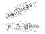
- FIG. 1illustrates a perspective attachment shaft second end view of the rotational connector device according to an embodiment of the invention
- FIG. 2illustrates a perspective plug end view of the device according to an embodiment of the invention
- FIG. 3illustrates a side view of the device according to an embodiment of the invention
- FIG. 4illustrates a cross-sectional view of the device according to an embodiment of the invention
- FIG. 5illustrates a perspective exploded view of the device according to an embodiment of the invention
- FIG. 6illustrates a side exploded view of the device according to an embodiment of the invention
- FIG. 7illustrates a cross-sectional exploded view of the device according to an embodiment of the invention.
- FIG. 8illustrates a perspective shaft end view of the device according to an embodiment of the invention
- FIG. 9illustrates a perspective plug end view of the device according to an embodiment of the invention.
- FIG. 10illustrates a side view of the device according to an embodiment of the invention.
- FIG. 11illustrates a cross-sectional view of the device according to an embodiment of the invention.
- FIG. 12illustrates a perspective exploded view of the device according to an embodiment of the invention
- FIG. 13illustrates a side exploded view of the device according to an embodiment of the invention.
- a rotational connector device 10may have a generally cylindrical housing 12 with a central cavity 14 and an opening at each end 16 , 18 .
- the bearing end 16may be sized for insertion of an annular bearing ring 20 that may have an inner member 22 and outer member 24 .
- the outer member 24may have a generally flat exterior perimeter surface 90 and a concave interior surface 92 for receipt of a convex exterior perimeter surface 94 of the inner member 22 .
- the mating of the surfaces 92 , 94may allow the inner member 22 to rotate within the outer member 24 such that when a shaft 30 may be positioned in the inner member 22 in aperture 96 that may have a generally flat annular interior surface the shaft may be rotated in the bearing ring 20 .
- a shaft 30may be inserted through the inner member 22 to position a first end 32 interior to the housing 12 and a second end 34 exterior to the housing 12 .
- the plug end 18 of the housing 12may be threaded for threadable attachment of a plug 40 to close the plug end 18 .
- the plug 40may have a concave interior end 42 that is shaped for compatible abutment of the first end 32 .
- a rotational connector device 10may be assembled by inserting the first end 32 through the inner member 22 of the bearing ring 20 to be retained by an annular step 36 and a fastener ring 60 engage in a groove 38 .
- the bearing ring 20may then be inserted in the cavity 14 to be retained against an annular step 50 spaced apart from the bearing end 16 of the housing 12 and against a fastener ring 62 sized to engage a groove 54 formed in the housing wall 52 adjacent the open bearing end 16 .
- the plug 40may be rotatably threaded into the housing 12 open plug end 16 until the concave interior end 42 is adjacent to the convex first end 32 of the shaft 30 at a desired position for the device 10 operation.
- the concave interior end 42may be spaced apart from the first end 32 a short distance such as 0.0002 to 0.010 inches to allow the first end 32 of the shaft 30 to freely rotate during normal operating conditions with the shaft 30 positioned in the housing 12 supported by the bearing ring 20 . This may reduce wear on the surfaces 32 , 42 .
- the plug 40may restrain movement of the shaft 30 in the housing 12 and bearing ring 20 to minimize damage.
- the plug 40may be positioned for the interior end 42 to abut the first end 32 of the shaft 30 .
- the plug 40may be retained at the position selected by a rotational locking device, for example, a pin, a key or like device.
- the locking devicemay also be structured with a lock ring 70 having protrusions 72 .
- the lock ring 70may be positioned over the outer end 46 of the plug 40 that may have slots 48 radially space around the perimeter positioned for compatibility with slots 19 formed in the housing wall 52 at the plug end 18 .
- the protrusions 72may engage adjacent slots 19 , 48 to fix the position of the plug 40 and the lock ring 70 may be retained in position by a fastener ring 76 in a groove 74 .
- the structure of the device 10may allow adjustment of the shaft 30 and plug 40 pressure interface without disassembly of the device 10 . Such an adjustment over time may allow longer life for the device.
- the elimination of a flange at the bearing end of the housing 12may allow for ease of repair of a device 10 by removal of fastener rings 60 , 62 for replacement of the bearing ring 20 or shaft 30 .
- an alternate rotational connector device 10may incorporate structure for longitudinal motion of the shaft 30 in the bearing ring 20 .
- the shaft 30may have a flange 28 or head at the first end 32 and the shaft 30 may be slidably inserted into the inner member 22 of the bearing ring 20 .
- the housing 12may have a rim 56 adjacent the bearing end 16 against which the bearing ring 20 may be positioned in the cavity 14 .
- a bearing sleeve 58may then be inserted in the cavity 14 to abut the bearing ring 20 and the plug 40 may be rotatably threaded into the plug end 18 of the housing to retain the bearing ring 20 in place.
- the plug 40may be retained in position as previously described by use of a rotational locking device.
- the interior end 44 of the plug 40may be generally flat since the first end 32 of the shaft 30 is positioned to allow longitudinal motion within the housing 12 .
- the housing 12may have a flange 80 and groove 84 formed as part of the external surface 53 of the housing wall 52 for use in retaining the device 10 in a structural arm or element of a vehicle.
- a snap ring 82may be positioned in the groove 84 .
- the shaft 30 second end 34may be formed for a press fit or fastener attachment to a vehicle structural element. The second end 34 may also be threaded for attachment.
Landscapes
- Engineering & Computer Science (AREA)
- General Engineering & Computer Science (AREA)
- Mechanical Engineering (AREA)
- Rolling Contact Bearings (AREA)
Abstract
Description
Claims (3)
Priority Applications (1)
| Application Number | Priority Date | Filing Date | Title |
|---|---|---|---|
| US12/455,839US8794860B1 (en) | 2009-06-08 | 2009-06-08 | Rotational connector device |
Applications Claiming Priority (1)
| Application Number | Priority Date | Filing Date | Title |
|---|---|---|---|
| US12/455,839US8794860B1 (en) | 2009-06-08 | 2009-06-08 | Rotational connector device |
Publications (1)
| Publication Number | Publication Date |
|---|---|
| US8794860B1true US8794860B1 (en) | 2014-08-05 |
Family
ID=51228957
Family Applications (1)
| Application Number | Title | Priority Date | Filing Date |
|---|---|---|---|
| US12/455,839Active2031-04-26US8794860B1 (en) | 2009-06-08 | 2009-06-08 | Rotational connector device |
Country Status (1)
| Country | Link |
|---|---|
| US (1) | US8794860B1 (en) |
Cited By (10)
| Publication number | Priority date | Publication date | Assignee | Title |
|---|---|---|---|---|
| CN106025929A (en)* | 2016-07-25 | 2016-10-12 | 云南电网有限责任公司昆明供电局 | Universal adapter connector for hot-line work |
| US20180119730A1 (en)* | 2015-04-24 | 2018-05-03 | Ndebele Paul | Ball joint with a retainer/safety nut that prevents accidental separation of the ball stud and the socket |
| US9982711B1 (en)* | 2016-11-30 | 2018-05-29 | ECC & Associates, LTD. | Adjustable ball joint |
| CN108547855A (en)* | 2018-04-25 | 2018-09-18 | 重庆卡福汽车制动转向系统有限公司 | Screw thread presses anti-rotation structure and its application method |
| US20230138722A1 (en)* | 2021-10-28 | 2023-05-04 | Honeywell International Inc. | Locking positioning systems |
| US20230279899A1 (en)* | 2018-06-27 | 2023-09-07 | Synergy Manufacturing, Inc. | Ball joint assembly |
| US20230294765A1 (en)* | 2022-03-15 | 2023-09-21 | Federal-Mogul Motorparts Llc | Socket joint and method of manufacturing |
| US11795994B1 (en) | 2019-12-16 | 2023-10-24 | Zhejiang Ruitai Suspension System Technology Ltd | Socket assembly with antirotation spring washer |
| US20240068508A1 (en)* | 2022-08-30 | 2024-02-29 | Federal-Mogul Motorparts Llc | Socket joint and pressure cup for a socket joint |
| US20240159264A1 (en)* | 2022-11-15 | 2024-05-16 | Brute Performance Inc | Adjustable ball joint for an inner tie rod assembly, adjustable ball joint kit, and method of assembling an adjustable ball joint |
Citations (19)
| Publication number | Priority date | Publication date | Assignee | Title |
|---|---|---|---|---|
| US1910926A (en)* | 1931-05-11 | 1933-05-23 | Vergil M Lutz | Steering device for motor vehicles |
| US3011219A (en) | 1958-04-14 | 1961-12-05 | American Metal Prod | Method of forming a ball joint utilizing a fluorocarbon layer |
| US3429598A (en)* | 1965-10-15 | 1969-02-25 | Moog Industries Inc | Ball joint unit for steerable vehicle wheels |
| US3854557A (en) | 1970-02-04 | 1974-12-17 | Airpot Corp | Universal joint for piston-connecting rod assembly |
| US3945739A (en) | 1973-11-29 | 1976-03-23 | Tokai Trw & Co., Ltd. | Ball joint |
| US4070121A (en) | 1976-12-20 | 1978-01-24 | Moog Automotive, Inc. | Wear indicating ball joint |
| US4154544A (en)* | 1977-10-31 | 1979-05-15 | Trw Inc. | Pivot joint |
| GB2268971A (en)* | 1992-07-23 | 1994-01-26 | Avm Inc | Captive ball joint end connector assembly |
| US5489161A (en) | 1993-02-22 | 1996-02-06 | Nhk Spring Co., Ltd. | Ball joint equipped with a dust cover |
| US5613792A (en) | 1994-06-29 | 1997-03-25 | Showa Corporation | Ball joint |
| US5655848A (en) | 1995-05-15 | 1997-08-12 | Chrysler Corporation | Suspension ball joint |
| US5799968A (en) | 1995-02-24 | 1998-09-01 | Loeffler; Fredrick L. | Ball joint assembly |
| US5885022A (en)* | 1997-07-15 | 1999-03-23 | Dana Corporation | Ball joint with polymer housing |
| US6095735A (en)* | 1999-06-21 | 2000-08-01 | Weinstein; Leslie J. | Locking nut assembly |
| US6190080B1 (en) | 1998-04-16 | 2001-02-20 | Central Corporation | Ball joint device for use in a vehicle |
| US6231264B1 (en)* | 1998-11-12 | 2001-05-15 | The Pullman Company | Torque rod bearing assembly |
| US6343889B1 (en) | 1998-09-28 | 2002-02-05 | Odyssey X-Treme Technologies, Inc. | Split-socket ball joint |
| US7144182B1 (en) | 2005-05-31 | 2006-12-05 | Qa1 Precision Products, Inc. | Ball joint construction |
| US7261487B2 (en) | 2003-07-31 | 2007-08-28 | Trw Automotive U.S. Llc | Composite ball joint bearing for a ball joint assembly |
- 2009
- 2009-06-08USUS12/455,839patent/US8794860B1/enactiveActive
Patent Citations (19)
| Publication number | Priority date | Publication date | Assignee | Title |
|---|---|---|---|---|
| US1910926A (en)* | 1931-05-11 | 1933-05-23 | Vergil M Lutz | Steering device for motor vehicles |
| US3011219A (en) | 1958-04-14 | 1961-12-05 | American Metal Prod | Method of forming a ball joint utilizing a fluorocarbon layer |
| US3429598A (en)* | 1965-10-15 | 1969-02-25 | Moog Industries Inc | Ball joint unit for steerable vehicle wheels |
| US3854557A (en) | 1970-02-04 | 1974-12-17 | Airpot Corp | Universal joint for piston-connecting rod assembly |
| US3945739A (en) | 1973-11-29 | 1976-03-23 | Tokai Trw & Co., Ltd. | Ball joint |
| US4070121A (en) | 1976-12-20 | 1978-01-24 | Moog Automotive, Inc. | Wear indicating ball joint |
| US4154544A (en)* | 1977-10-31 | 1979-05-15 | Trw Inc. | Pivot joint |
| GB2268971A (en)* | 1992-07-23 | 1994-01-26 | Avm Inc | Captive ball joint end connector assembly |
| US5489161A (en) | 1993-02-22 | 1996-02-06 | Nhk Spring Co., Ltd. | Ball joint equipped with a dust cover |
| US5613792A (en) | 1994-06-29 | 1997-03-25 | Showa Corporation | Ball joint |
| US5799968A (en) | 1995-02-24 | 1998-09-01 | Loeffler; Fredrick L. | Ball joint assembly |
| US5655848A (en) | 1995-05-15 | 1997-08-12 | Chrysler Corporation | Suspension ball joint |
| US5885022A (en)* | 1997-07-15 | 1999-03-23 | Dana Corporation | Ball joint with polymer housing |
| US6190080B1 (en) | 1998-04-16 | 2001-02-20 | Central Corporation | Ball joint device for use in a vehicle |
| US6343889B1 (en) | 1998-09-28 | 2002-02-05 | Odyssey X-Treme Technologies, Inc. | Split-socket ball joint |
| US6231264B1 (en)* | 1998-11-12 | 2001-05-15 | The Pullman Company | Torque rod bearing assembly |
| US6095735A (en)* | 1999-06-21 | 2000-08-01 | Weinstein; Leslie J. | Locking nut assembly |
| US7261487B2 (en) | 2003-07-31 | 2007-08-28 | Trw Automotive U.S. Llc | Composite ball joint bearing for a ball joint assembly |
| US7144182B1 (en) | 2005-05-31 | 2006-12-05 | Qa1 Precision Products, Inc. | Ball joint construction |
Cited By (15)
| Publication number | Priority date | Publication date | Assignee | Title |
|---|---|---|---|---|
| US20180119730A1 (en)* | 2015-04-24 | 2018-05-03 | Ndebele Paul | Ball joint with a retainer/safety nut that prevents accidental separation of the ball stud and the socket |
| US10677284B2 (en)* | 2015-04-24 | 2020-06-09 | Ndebele Paul | Ball joint with a retainer/safety nut that prevents accidental separation of the ball stud and the socket |
| CN106025929A (en)* | 2016-07-25 | 2016-10-12 | 云南电网有限责任公司昆明供电局 | Universal adapter connector for hot-line work |
| CN106025929B (en)* | 2016-07-25 | 2018-06-08 | 云南电网有限责任公司昆明供电局 | A kind of universal crossover sub for livewire work |
| US9982711B1 (en)* | 2016-11-30 | 2018-05-29 | ECC & Associates, LTD. | Adjustable ball joint |
| CN108547855A (en)* | 2018-04-25 | 2018-09-18 | 重庆卡福汽车制动转向系统有限公司 | Screw thread presses anti-rotation structure and its application method |
| US12378990B2 (en)* | 2018-06-27 | 2025-08-05 | Synergy Manufacturing, Inc. | Ball joint assembly |
| US20230279899A1 (en)* | 2018-06-27 | 2023-09-07 | Synergy Manufacturing, Inc. | Ball joint assembly |
| US11795994B1 (en) | 2019-12-16 | 2023-10-24 | Zhejiang Ruitai Suspension System Technology Ltd | Socket assembly with antirotation spring washer |
| US20230138722A1 (en)* | 2021-10-28 | 2023-05-04 | Honeywell International Inc. | Locking positioning systems |
| US20230294765A1 (en)* | 2022-03-15 | 2023-09-21 | Federal-Mogul Motorparts Llc | Socket joint and method of manufacturing |
| US20240068508A1 (en)* | 2022-08-30 | 2024-02-29 | Federal-Mogul Motorparts Llc | Socket joint and pressure cup for a socket joint |
| US12435753B2 (en)* | 2022-08-30 | 2025-10-07 | Federal-Mogul Motorparts Llc | Socket joint and pressure cup for a socket joint |
| US20240159264A1 (en)* | 2022-11-15 | 2024-05-16 | Brute Performance Inc | Adjustable ball joint for an inner tie rod assembly, adjustable ball joint kit, and method of assembling an adjustable ball joint |
| US12366263B2 (en)* | 2022-11-15 | 2025-07-22 | Brute Performance, Inc | Adjustable ball joint for an inner tie rod assembly, adjustable ball joint kit, and method of assembling an adjustable ball joint |
Similar Documents
| Publication | Publication Date | Title |
|---|---|---|
| US8794860B1 (en) | Rotational connector device | |
| CN100398850C (en) | Coniform gernel | |
| JP3924365B2 (en) | Dust absorption adapter | |
| JP6557150B2 (en) | Link arm assembly | |
| US6692179B2 (en) | Spherical sleeve joint | |
| JP4861307B2 (en) | Suspension joints and bearings | |
| KR20140085445A (en) | Device for connecting two conduit sections | |
| KR20170088876A (en) | Ball joint assembly | |
| WO2016190385A1 (en) | Ball joint | |
| ES2275150T3 (en) | EXTREME CONNECTION DEVICE FOR A CONTROL CABLE, WITH SYSTEM TO ENSURE A CORRECT ASSEMBLY. | |
| JP4555096B2 (en) | Assembly structure of holding member, shaft and snap ring | |
| EP1308316A1 (en) | Bearing device for axle | |
| JP2003148506A (en) | Method for mutually fixing member by spring ring and its assembly | |
| WO2013000517A1 (en) | Spherical plain bearing with constant torque | |
| US9065307B2 (en) | Apparatus for facilitating attachment of fan and flywheel in an internal combustion engine | |
| CN111868396B (en) | Improved socket assembly and method of making same | |
| CA2604121A1 (en) | Metal split bearing compression load ball joint | |
| EP1942014B1 (en) | A sealing arrangement between a constant velocity joint and a hub bearing unit of a motor vehicle wheel | |
| EP1302681A2 (en) | Ball joint with dual studs | |
| US20150057091A1 (en) | Retainer cap for shaft assembly | |
| KR101934011B1 (en) | Drive shaft for vehicle | |
| US10281947B2 (en) | Mounting assembly for a control pedal of a vehicle | |
| US8069539B2 (en) | Universal end fitting and fastener assembly comprising such an end fitting | |
| TWI798239B (en) | Bearing race and seal driver tool and method of installing bearing race | |
| JP2008281099A (en) | Center bearing support |
Legal Events
| Date | Code | Title | Description |
|---|---|---|---|
| STCF | Information on status: patent grant | Free format text:PATENTED CASE | |
| FEPP | Fee payment procedure | Free format text:MAINTENANCE FEE REMINDER MAILED (ORIGINAL EVENT CODE: REM.) | |
| FEPP | Fee payment procedure | Free format text:SURCHARGE FOR LATE PAYMENT, SMALL ENTITY (ORIGINAL EVENT CODE: M2554) | |
| MAFP | Maintenance fee payment | Free format text:PAYMENT OF MAINTENANCE FEE, 4TH YR, SMALL ENTITY (ORIGINAL EVENT CODE: M2551) Year of fee payment:4 | |
| AS | Assignment | Owner name:DYNATRAC PRODUCTS, LLC, CALIFORNIA Free format text:ASSIGNMENT OF ASSIGNORS INTEREST;ASSIGNOR:DYNATRAC PRODUCTS CO., INC.;REEL/FRAME:058388/0229 Effective date:20211210 Owner name:DYNATRAC PRODUCTS CO., INC., CALIFORNIA Free format text:ASSIGNMENT OF ASSIGNORS INTEREST;ASSIGNOR:MCGEAN, JAMES W.;REEL/FRAME:058386/0283 Effective date:20211210 | |
| AS | Assignment | Owner name:BMO HARRIS BANK N.A., AS COLLATERAL AGENT, ILLINOIS Free format text:INTELLECTUAL PROPERTY SECURITY AGREEMENT;ASSIGNORS:DYNATRAC PRODUCTS, LLC;ICON VEHICLE DYNAMICS LLC;REEL/FRAME:058576/0435 Effective date:20211223 | |
| MAFP | Maintenance fee payment | Free format text:PAYMENT OF MAINTENANCE FEE, 8TH YR, SMALL ENTITY (ORIGINAL EVENT CODE: M2552); ENTITY STATUS OF PATENT OWNER: SMALL ENTITY Year of fee payment:8 | |
| AS | Assignment | Owner name:BARINGS FINANCE LLC, AS COLLATERAL AGENT, NORTH CAROLINA Free format text:SECURITY INTEREST;ASSIGNORS:DYNATRAC PRODUCTS, LLC;RING & PINION SERVICE INC.;ICON VEHICLE DYNAMICS LLC;REEL/FRAME:061613/0507 Effective date:20221101 | |
| AS | Assignment | Owner name:ICON VEHICLE DYNAMICS LLC, CALIFORNIA Free format text:RELEASE BY SECURED PARTY;ASSIGNOR:BMO HARRIS BANK N.A.;REEL/FRAME:061637/0229 Effective date:20221101 Owner name:DYNATRAC PRODUCTS LLC, CALIFORNIA Free format text:RELEASE BY SECURED PARTY;ASSIGNOR:BMO HARRIS BANK N.A.;REEL/FRAME:061637/0229 Effective date:20221101 |