US8794781B2 - Umbrella apparatus - Google Patents
Umbrella apparatusDownload PDFInfo
- Publication number
- US8794781B2 US8794781B2US10/650,537US65053703AUS8794781B2US 8794781 B2US8794781 B2US 8794781B2US 65053703 AUS65053703 AUS 65053703AUS 8794781 B2US8794781 B2US 8794781B2
- Authority
- US
- United States
- Prior art keywords
- umbrella
- power system
- umbrella apparatus
- electrical power
- power
- Prior art date
- Legal status (The legal status is an assumption and is not a legal conclusion. Google has not performed a legal analysis and makes no representation as to the accuracy of the status listed.)
- Expired - Lifetime, expires
Links
- 230000008878couplingEffects0.000claimsdescription10
- 238000010168coupling processMethods0.000claimsdescription10
- 238000005859coupling reactionMethods0.000claimsdescription10
- 239000000463materialSubstances0.000claimsdescription10
- 239000004020conductorSubstances0.000claims1
- 230000002708enhancing effectEffects0.000claims1
- 238000001816coolingMethods0.000abstractdescription29
- 230000000694effectsEffects0.000abstractdescription3
- 238000009429electrical wiringMethods0.000description10
- XLYOFNOQVPJJNP-UHFFFAOYSA-NwaterSubstancesOXLYOFNOQVPJJNP-UHFFFAOYSA-N0.000description10
- 239000003595mistSubstances0.000description9
- 230000008901benefitEffects0.000description5
- 238000010586diagramMethods0.000description5
- 239000012530fluidSubstances0.000description5
- 230000007246mechanismEffects0.000description4
- 108091060210Heavy strandProteins0.000description3
- OAICVXFJPJFONN-UHFFFAOYSA-NPhosphorusChemical group[P]OAICVXFJPJFONN-UHFFFAOYSA-N0.000description2
- 238000010438heat treatmentMethods0.000description2
- 238000004519manufacturing processMethods0.000description2
- QSHDDOUJBYECFT-UHFFFAOYSA-NmercuryChemical compound[Hg]QSHDDOUJBYECFT-UHFFFAOYSA-N0.000description2
- 230000004048modificationEffects0.000description2
- 238000012986modificationMethods0.000description2
- 230000004044responseEffects0.000description2
- 230000005540biological transmissionEffects0.000description1
- OJIJEKBXJYRIBZ-UHFFFAOYSA-Ncadmium nickelChemical compound[Ni].[Cd]OJIJEKBXJYRIBZ-UHFFFAOYSA-N0.000description1
- 230000008859changeEffects0.000description1
- 239000011248coating agentSubstances0.000description1
- 238000000576coating methodMethods0.000description1
- 239000013078crystalSubstances0.000description1
- 238000001514detection methodMethods0.000description1
- 238000005265energy consumptionMethods0.000description1
- 108010036050human cationic antimicrobial protein 57Proteins0.000description1
- 230000003993interactionEffects0.000description1
- 210000003141lower extremityAnatomy0.000description1
- 239000000203mixtureSubstances0.000description1
- 238000010417needleworkMethods0.000description1
- 231100000989no adverse effectToxicity0.000description1
- 229910052698phosphorusInorganic materials0.000description1
- 239000011574phosphorusSubstances0.000description1
- 238000004804windingMethods0.000description1
Images


Classifications
- F—MECHANICAL ENGINEERING; LIGHTING; HEATING; WEAPONS; BLASTING
- F24—HEATING; RANGES; VENTILATING
- F24F—AIR-CONDITIONING; AIR-HUMIDIFICATION; VENTILATION; USE OF AIR CURRENTS FOR SCREENING
- F24F5/00—Air-conditioning systems or apparatus not covered by F24F1/00 or F24F3/00, e.g. using solar heat or combined with household units such as an oven or water heater
- F24F5/0007—Air-conditioning systems or apparatus not covered by F24F1/00 or F24F3/00, e.g. using solar heat or combined with household units such as an oven or water heater cooling apparatus specially adapted for use in air-conditioning
- F24F5/0035—Air-conditioning systems or apparatus not covered by F24F1/00 or F24F3/00, e.g. using solar heat or combined with household units such as an oven or water heater cooling apparatus specially adapted for use in air-conditioning using evaporation
- A—HUMAN NECESSITIES
- A45—HAND OR TRAVELLING ARTICLES
- A45B—WALKING STICKS; UMBRELLAS; LADIES' OR LIKE FANS
- A45B25/00—Details of umbrellas
- A45B25/14—Devices for opening and for closing umbrellas
- A45B25/143—Devices for opening and for closing umbrellas automatic
- A—HUMAN NECESSITIES
- A45—HAND OR TRAVELLING ARTICLES
- A45B—WALKING STICKS; UMBRELLAS; LADIES' OR LIKE FANS
- A45B3/00—Sticks combined with other objects
- A—HUMAN NECESSITIES
- A45—HAND OR TRAVELLING ARTICLES
- A45B—WALKING STICKS; UMBRELLAS; LADIES' OR LIKE FANS
- A45B3/00—Sticks combined with other objects
- A45B3/02—Sticks combined with other objects with illuminating devices
- A45B3/04—Sticks combined with other objects with illuminating devices electrical
- F—MECHANICAL ENGINEERING; LIGHTING; HEATING; WEAPONS; BLASTING
- F21—LIGHTING
- F21V—FUNCTIONAL FEATURES OR DETAILS OF LIGHTING DEVICES OR SYSTEMS THEREOF; STRUCTURAL COMBINATIONS OF LIGHTING DEVICES WITH OTHER ARTICLES, NOT OTHERWISE PROVIDED FOR
- F21V33/00—Structural combinations of lighting devices with other articles, not otherwise provided for
- F21V33/006—General building constructions or finishing work for buildings, e.g. roofs, gutters, stairs or floors; Garden equipment; Sunshades or parasols
- F—MECHANICAL ENGINEERING; LIGHTING; HEATING; WEAPONS; BLASTING
- F21—LIGHTING
- F21V—FUNCTIONAL FEATURES OR DETAILS OF LIGHTING DEVICES OR SYSTEMS THEREOF; STRUCTURAL COMBINATIONS OF LIGHTING DEVICES WITH OTHER ARTICLES, NOT OTHERWISE PROVIDED FOR
- F21V33/00—Structural combinations of lighting devices with other articles, not otherwise provided for
- F21V33/0088—Ventilating systems
- F21V33/0096—Fans, e.g. ceiling fans
- F—MECHANICAL ENGINEERING; LIGHTING; HEATING; WEAPONS; BLASTING
- F24—HEATING; RANGES; VENTILATING
- F24F—AIR-CONDITIONING; AIR-HUMIDIFICATION; VENTILATION; USE OF AIR CURRENTS FOR SCREENING
- F24F5/00—Air-conditioning systems or apparatus not covered by F24F1/00 or F24F3/00, e.g. using solar heat or combined with household units such as an oven or water heater
- F24F5/0046—Air-conditioning systems or apparatus not covered by F24F1/00 or F24F3/00, e.g. using solar heat or combined with household units such as an oven or water heater using natural energy, e.g. solar energy, energy from the ground
- A—HUMAN NECESSITIES
- A45—HAND OR TRAVELLING ARTICLES
- A45B—WALKING STICKS; UMBRELLAS; LADIES' OR LIKE FANS
- A45B23/00—Other umbrellas
- A45B2023/0012—Ground supported umbrellas or sunshades on a single post, e.g. resting in or on a surface there below
- A—HUMAN NECESSITIES
- A45—HAND OR TRAVELLING ARTICLES
- A45B—WALKING STICKS; UMBRELLAS; LADIES' OR LIKE FANS
- A45B2200/00—Details not otherwise provided for in A45B
- A45B2200/10—Umbrellas; Sunshades
- A45B2200/1009—Umbrellas; Sunshades combined with other objects
- A45B2200/1027—Umbrellas; Sunshades combined with other objects with means for generating solar energy
- A—HUMAN NECESSITIES
- A45—HAND OR TRAVELLING ARTICLES
- A45B—WALKING STICKS; UMBRELLAS; LADIES' OR LIKE FANS
- A45B2200/00—Details not otherwise provided for in A45B
- A45B2200/10—Umbrellas; Sunshades
- A45B2200/1009—Umbrellas; Sunshades combined with other objects
- A45B2200/1036—Umbrellas; Sunshades combined with other objects with means for promoting air movement, e.g. ventilation holes, fans, ventilators, special shape for ventilation, suction means
- A—HUMAN NECESSITIES
- A45—HAND OR TRAVELLING ARTICLES
- A45B—WALKING STICKS; UMBRELLAS; LADIES' OR LIKE FANS
- A45B2200/00—Details not otherwise provided for in A45B
- A45B2200/10—Umbrellas; Sunshades
- A45B2200/1009—Umbrellas; Sunshades combined with other objects
- A45B2200/1045—Umbrellas; Sunshades combined with other objects with a misting device having at least one nozzle for spraying a fluid, e.g. water
- F—MECHANICAL ENGINEERING; LIGHTING; HEATING; WEAPONS; BLASTING
- F21—LIGHTING
- F21S—NON-PORTABLE LIGHTING DEVICES; SYSTEMS THEREOF; VEHICLE LIGHTING DEVICES SPECIALLY ADAPTED FOR VEHICLE EXTERIORS
- F21S9/00—Lighting devices with a built-in power supply; Systems employing lighting devices with a built-in power supply
- F21S9/02—Lighting devices with a built-in power supply; Systems employing lighting devices with a built-in power supply the power supply being a battery or accumulator
- F21S9/03—Lighting devices with a built-in power supply; Systems employing lighting devices with a built-in power supply the power supply being a battery or accumulator rechargeable by exposure to light
- Y—GENERAL TAGGING OF NEW TECHNOLOGICAL DEVELOPMENTS; GENERAL TAGGING OF CROSS-SECTIONAL TECHNOLOGIES SPANNING OVER SEVERAL SECTIONS OF THE IPC; TECHNICAL SUBJECTS COVERED BY FORMER USPC CROSS-REFERENCE ART COLLECTIONS [XRACs] AND DIGESTS
- Y02—TECHNOLOGIES OR APPLICATIONS FOR MITIGATION OR ADAPTATION AGAINST CLIMATE CHANGE
- Y02A—TECHNOLOGIES FOR ADAPTATION TO CLIMATE CHANGE
- Y02A30/00—Adapting or protecting infrastructure or their operation
- Y02A30/27—Relating to heating, ventilation or air conditioning [HVAC] technologies
- Y02A30/272—Solar heating or cooling
- Y—GENERAL TAGGING OF NEW TECHNOLOGICAL DEVELOPMENTS; GENERAL TAGGING OF CROSS-SECTIONAL TECHNOLOGIES SPANNING OVER SEVERAL SECTIONS OF THE IPC; TECHNICAL SUBJECTS COVERED BY FORMER USPC CROSS-REFERENCE ART COLLECTIONS [XRACs] AND DIGESTS
- Y02—TECHNOLOGIES OR APPLICATIONS FOR MITIGATION OR ADAPTATION AGAINST CLIMATE CHANGE
- Y02B—CLIMATE CHANGE MITIGATION TECHNOLOGIES RELATED TO BUILDINGS, e.g. HOUSING, HOUSE APPLIANCES OR RELATED END-USER APPLICATIONS
- Y02B10/00—Integration of renewable energy sources in buildings
- Y02B10/10—Photovoltaic [PV]
- Y—GENERAL TAGGING OF NEW TECHNOLOGICAL DEVELOPMENTS; GENERAL TAGGING OF CROSS-SECTIONAL TECHNOLOGIES SPANNING OVER SEVERAL SECTIONS OF THE IPC; TECHNICAL SUBJECTS COVERED BY FORMER USPC CROSS-REFERENCE ART COLLECTIONS [XRACs] AND DIGESTS
- Y02—TECHNOLOGIES OR APPLICATIONS FOR MITIGATION OR ADAPTATION AGAINST CLIMATE CHANGE
- Y02B—CLIMATE CHANGE MITIGATION TECHNOLOGIES RELATED TO BUILDINGS, e.g. HOUSING, HOUSE APPLIANCES OR RELATED END-USER APPLICATIONS
- Y02B10/00—Integration of renewable energy sources in buildings
- Y02B10/20—Solar thermal
- Y—GENERAL TAGGING OF NEW TECHNOLOGICAL DEVELOPMENTS; GENERAL TAGGING OF CROSS-SECTIONAL TECHNOLOGIES SPANNING OVER SEVERAL SECTIONS OF THE IPC; TECHNICAL SUBJECTS COVERED BY FORMER USPC CROSS-REFERENCE ART COLLECTIONS [XRACs] AND DIGESTS
- Y02—TECHNOLOGIES OR APPLICATIONS FOR MITIGATION OR ADAPTATION AGAINST CLIMATE CHANGE
- Y02B—CLIMATE CHANGE MITIGATION TECHNOLOGIES RELATED TO BUILDINGS, e.g. HOUSING, HOUSE APPLIANCES OR RELATED END-USER APPLICATIONS
- Y02B20/00—Energy efficient lighting technologies, e.g. halogen lamps or gas discharge lamps
- Y02B20/72—Energy efficient lighting technologies, e.g. halogen lamps or gas discharge lamps in street lighting
- Y—GENERAL TAGGING OF NEW TECHNOLOGICAL DEVELOPMENTS; GENERAL TAGGING OF CROSS-SECTIONAL TECHNOLOGIES SPANNING OVER SEVERAL SECTIONS OF THE IPC; TECHNICAL SUBJECTS COVERED BY FORMER USPC CROSS-REFERENCE ART COLLECTIONS [XRACs] AND DIGESTS
- Y02—TECHNOLOGIES OR APPLICATIONS FOR MITIGATION OR ADAPTATION AGAINST CLIMATE CHANGE
- Y02B—CLIMATE CHANGE MITIGATION TECHNOLOGIES RELATED TO BUILDINGS, e.g. HOUSING, HOUSE APPLIANCES OR RELATED END-USER APPLICATIONS
- Y02B30/00—Energy efficient heating, ventilation or air conditioning [HVAC]
- Y02B30/54—Free-cooling systems
Definitions
- the present inventionrelates in general to patio umbrellas, and in particular, to an improved patio umbrella with integral lighting system and other modular electronic systems and components.
- LED'slight emitting diodes
- florescent lightsto provide relatively bright outdoor light for reading and other activities that require relatively high light intensities.
- lighting systemssuch as those utilizing cold cathode tubes, LED's, or florescent lights
- cooling systemssuch as those utilizing electric fans or misting systems
- motorized retraction systemscan be selectively interchanged.
- the above objectsare achieved, for example, by integrating a rechargeable power system, a lighting system, a motorized retraction system, and/or a cooling system into a relatively large patio umbrella.
- the resulting umbrelladoes not have to be connected to a household electrical system, is a relatively low power consuming device, does not generate much heat, provides a high amount of light intensity, reduces the overall energy consumption of outdoor lighting, allows for fewer batteries to be utilized in each lighting fixture, allows for easier recharging of the batteries due to the lower power requirements, and allows the utilization of smaller photovoltaic solar cells.
- the cold cathode tubemay be operated at multiple voltage levels to provide differing amounts of light output.
- a wireless receiver and transmitter pairmay be utilized to allow an operator to use a wireless command signal to change the operating state of the lighting system, such as switching the system between an on and off condition, and switching the system between varying levels of light output. Accordingly, an operator may intensify the light output from the lighting system through use of a wireless handheld transmitter when he wants additional light from a particular umbrella.
- FIG. 1is a fragmentary and sectional view of the preferred embodiment of the lighted umbrella with motorized opening and closing system according to the present invention.
- FIGS. 2A , 2 B, and 2 Care pictorial, fragmentary, and section views of an alternate embodiment of the present invention which is directed to a lighted umbrella with a stand and a single battery and removable base cover.
- FIGS. 3A , 3 B, and 3 Care pictorial, fragmentary, and partial section views of another alternate embodiment of the present invention which is directed to a lighted umbrella with a stand, charger, batteries, and removable battery cover.
- FIG. 4Ais a fragmentary and sectional view of another alternate embodiment of the present invention which is directed to a lighted umbrella with recessed lighting.
- FIG. 4Bis a fragmentary and sectional view of another alternate embodiment of the present invention which is directed to a lighted umbrella with integral misting system.
- FIG. 4Cis a fragmentary and sectional view of another alternate embodiment of the present invention which is directed to a lighted umbrella with an integral fan system.
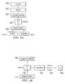
- FIG. 5Ais a block diagram representation of the motorized opening and closing system of the umbrella of FIG. 1 and of the other embodiments of the umbrella of the present invention.
- FIG. 5Bis a block diagram representation of an alternate embodiment of the motorized opening and closing system of FIG. 5A .
- FIG. 6is a simplified schematic of an alternative embodiment of the present invention which is directed to a lighted umbrella with a top-mounted power unit and a cold cathode tube lighting system.
- FIG. 7is a simplified schematic of an alternative embodiment of the present invention which is directed to an umbrella with a top-mounted power unit and an electric fan cooling system.
- FIG. 8is a simplified view of an alternative embodiment of the present invention which is directed to an umbrella with a top-mounted power unit and a mist producing cooling system.
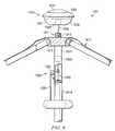
- FIG. 9is a simplified schematic of an alternate embodiment of the present invention that is directed to an umbrella with a top-mounted power unit and a motorized opening and closing system.
- FIG. 10is a schematic of one broad implementation of the present invention.
- FIG. 11is a block diagram representation of the present invention.
- Umbrella apparatus 11includes an umbrella portion 13 and a hollow tubular pole portion 15 .
- Pole portion 15is coupled to and supports umbrella portion 13 .
- Umbrella portion 13is preferably retractable and may be moved between a raised, or expanded open position, which is shown; and a lowered, or retracted, closed position in which umbrella portion is collapsed down about pole portion 15 , as is conventional.
- a flexible canopy 17is attached to and covers umbrella portion 15 .
- Canopy 17is supported by a plurality of rib members 19 , 21 , 23 , and 25 .
- Rib members 19 , 21 , 23 , and 25are preferably hingedly coupled to pole portion 15 at an upper portion of pole portion 15 .
- An integral lighting system 26is carried by at least one of rib members 19 , 21 , 23 , or 25 . Lighting system 26 provides high intensity light to umbrella apparatus 11 and the surrounding area. In the embodiment of FIG. 1 , lighting system 26 preferably utilizes a cold cathode tube which will be described in greater detail herein.
- Umbrella apparatus 11may include a base member adapted to receive pole portion 15 and to support umbrella apparatus 11 in a generally upright position.
- FIG. 1other embodiments of the present invention depict a variety of conventional and novel base members, any of which may be utilized with the embodiment of FIG. 1 .
- umbrella apparatus 11may be used with little or no base member whatsoever, provided there is a table or some other support structure, including the ground, which may be adapted to receive pole portion 15 .
- many patio tablesare designed with central apertures to receive, support, and stabilize relatively large umbrellas. In some cases, the patio tables eliminate the need for a base member all together.
- light system 26includes a plurality of light strands 27 , 29 , 31 , and 33 attached to rib members 19 , 21 , 23 , and 25 .
- Each light strand 27 , 29 , 31 , and 33includes electrical wiring 39 which conductively connects a plurality of small cold cathode tube light bulbs together for providing the high intensity light under canopy 17 and in the area surrounding umbrella apparatus 11 .
- a wiring ring 37secures and locates electrical wiring 39 of light strands 27 , 29 , 31 , and 33 , so that electrical wiring 39 may be passed through the hollow interior of pole portion 15 to a power source, as will be described in detail below.
- Umbrella apparatus 11includes an optional opening and closing system 40 that aids in expanding umbrella portion 13 into the open condition and retracting umbrella portion 13 into the closed condition.
- Opening and closing system 40includes a cable system 41 , a gear and pulley system 43 housed in a crank case 44 , and a manual crank 45 .
- Crank case 44is preferably located on pole portion 15 such that crank case 44 is accessible when umbrella portion 13 is in the fully retracted position against pole portion 15 .
- Cable system 41is coupled between rib members 19 , 21 , 23 , and 25 and gear and pulley system 43 , and is preferably disposed within the hollow interior of pole portion 15 .
- Manual crank 45is coupled to gear and pulley system 43 so as to allow manual opening and closing of umbrella portion 13 .
- Opening and closing system 40may be automated by the inclusion of an electric screw driver motor 49 , or other similar relatively small diameter motor assembly, and one or more operational switches 47 .
- Motor 49is preferably disposed within the hollow interior of pole portion 15 and is coupled to gear and pulley system 43 .
- Operational switches 47are preferably carried by crank case 44 , and include one or more switches for controlling the operation of motor 49 .
- a usermay expand and retract umbrella portion 13 simply by pressing the appropriate operational switch 47 . This feature is particularly advantageous when used with large umbrellas which may be relatively heavy and awkward to operate, or when the user lacks sufficient strength to expand or retract umbrella portion 13 .
- Umbrella apparatus 11includes a power system 50 having a power source 55 .
- power source 55is preferably disposed in the hollow interior of pole portion 15 at a lower extremity and comprises one or more rechargeable batteries 55 a .
- a releasable end cap 57 having integral ground connectorsis provided at the lowermost portion of pole portion 15 to complete the electrical circuit of power system 50 and to allow access to rechargeable batteries 55 a , as rechargeable batteries 55 a may have to be periodically replaced.
- Power system 50provides electrical power to lighting system 26 and opening and closing system 40 .
- An external power system charger 51is electrically coupled to power system 50 to aid in repeatedly charging rechargeable batteries 55 a .
- an external adapter 60may be provided.
- External adapter 60includes a relatively small plug 59 that is adapted to be conductively received by external power system charger 51 , an extension cord 61 , an electrical transformer 63 , and terminals 65 that allow transformer 63 to be plugged into a conventional AC wall outlet. This allows power system charger 51 to receive power directly from a conventional AC wall outlet in order to recharge rechargeable batteries 55 a.
- an alternative power system charger 62may be provided.
- Alternate power system charger 62includes at least one solar cell 35 carried by an upper cap portion 64 .
- Solar cells 35are conductively coupled to power system charger 51 via wires (not shown) that pass through the hollow interior of pole portion 15 , thereby allowing solar cells 35 to provide an electrical charge to recharge rechargeable batteries 55 a , provided sunlight falls upon solar cells 35 .
- solar cells 35provide continuous recharging throughout the daylight hours, the amount and frequency of charging power system 50 with external power system charger 60 may be minimized. It is important to note that locating alternate power system charger 62 atop umbrella portion 13 is unique and advantageous, particularly when alternate power system charger 62 includes solar cells 35 or other types of solar energy collectors. Such location limits the visibility of alternate power system charger 62 and ensures that solar energy collection is maximized.
- FIG. 1The embodiment depicted in FIG. 1 is advantageous over the prior art in that it provides a number of useful functions.
- Umbrella apparatus 11is lighted by lighting system 26 which does not require continuous access to a conventional AC wall outlet, while providing high intensity light. This allows umbrella apparatus 11 to be placed in a relatively remote lawn or garden locations that are away from, or substantially removed from, conventional AC power outlets.
- solar cells 35provide a continuous trickle charge to recharge rechargeable batteries 55 a , thereby reducing the need for and frequency of use of external power system charger 60 .
- external power system charger 60may be utilized to directly charge power system charger 51 .
- a conventional extension cordmay be used, thereby eliminating the need to move umbrella apparatus 11 from its remote location to a location near an AC power outlet.
- an umbrella apparatus 111includes an umbrella portion 113 , a pole portion 115 , a stand portion 118 , and a base portion 120 adapted to house a rechargeable power system 151 .
- Umbrella apparatus 11includes a lighting system 126 and may include a motorized opening and closing system 140 .
- Umbrella portion 113is preferably retractable and may be moved between a raised, or expanded open position, which is shown; and a lowered, or retracted, closed position in which umbrella portion is collapsed down about pole portion 115 , as is conventional.
- a flexible canopy 117is attached to and covers umbrella portion 115 .
- Canopy 117is supported by a plurality of rib members 119 , 121 , 123 , and 125 .
- Rib members 119 , 121 , 123 , and 125are preferably hingedly coupled to pole portion 115 at an upper portion of pole portion 115 .
- An integral lighting system 126is carried by at least one of rib members 119 , 121 , 123 , or 125 .
- Lighting system 126provides high intensity light to umbrella apparatus 111 and the surrounding area. In the embodiment of FIGS. 2A-2C , lighting system 126 preferably utilizes a cold cathode tube which will be described in greater detail herein.
- Lighting system 126includes a plurality of light strands 127 , 129 , 131 , and 133 attached to rib members 119 , 121 , 123 , and 125 .
- Each light strand 127 , 129 , 131 , and 133includes electrical wiring 139 which conductively couples a plurality of small cold cathode tube light bulbs together for providing the high intensity light under canopy 117 and in the area surrounding umbrella apparatus 111 .
- a wiring ring 137secures and locates electrical wiring 139 of light strands 127 , 129 , 131 , and 133 , so that electrical wiring 139 may be passed through the hollow interior of pole portion 115 to a power source, as will be described in detail below.
- Umbrella apparatus 111includes an optional opening and closing system 140 that aids in expanding umbrella portion 113 into the open condition and retracting umbrella portion 113 into the closed condition.
- Opening and closing system 140includes a cable system 141 , a gear and pulley system 143 housed in a crank case 144 , and a manual crank 145 .
- Crank case 144is preferably located on pole portion 115 such that crank case 144 is accessible when umbrella portion 113 is in the fully retracted position against pole portion 115 .
- Cable system 141is coupled between rib members 119 , 121 , 123 , and 125 and gear and pulley system 143 , and is preferably disposed within the hollow interior of pole portion 115 .
- Manual crank 145is coupled to gear and pulley system 143 so as to allow manual opening and closing of umbrella portion 113 .
- Opening and closing system 140may be automated by the inclusion of an electric screw driver motor 149 , or other similar relatively small diameter motor assembly, and one or more operational switches 147 .
- Motor 149is preferably disposed within the hollow interior of pole portion 115 and is coupled to gear and pulley system 143 .
- Operational switches 147are preferably carried by crank case 144 , and include one or more switches for controlling the operation of motor 149 .
- a usermay expand and retract umbrella portion 113 simply by pressing the appropriate operational switch 147 . This feature is particularly advantageous when used with large umbrellas which may be relatively heavy and awkward to operate, or when the user lacks sufficient strength to expand or retract umbrella portion 113 .
- Umbrella apparatus 111includes a power system 150 having a power source 155 .
- power source 155is preferably adapted to be conductively coupled to base portion 120 and comprises a rechargeable battery pack 155 a , preferably an 18-Volt rechargeable battery pack.
- Battery pack 155 ais preferably the type of rechargeable battery that is utilized with most modern cordless power tools, such as drills, saws, and sanders.
- Battery pack 155 ais adapted to be repeatedly recharged by plugging battery pack 155 a into a conventional charger (not shown) that is plugged into a conventional AC power outlet.
- Power system 150provides electrical power to lighting system 126 and opening and closing system 140 .
- an alternative power system charger 162may be provided.
- Alternate power system charger 162includes at least one solar cell 135 carried by an upper cap portion 164 .
- Solar cells 135are conductively coupled to power system 150 via wires (not shown) that pass through the hollow interior of pole portion 115 , thereby allowing solar cells 135 to provide an electrical charge to recharge rechargeable battery pack 155 a , provided sunlight falls upon solar cells 135 . Because solar cells 135 provide continuous recharging throughout the daylight hours, the frequency with which battery pack 155 a must be replaced or recharged may be minimized.
- alternate power system charger 162 atop umbrella portion 113is unique and advantageous, particularly when alternate power system charger 162 includes solar cells 135 or other types of solar energy collectors. Such location limits the visibility of alternate power system charger 162 and ensures that solar energy collection is maximized.
- Stand portion 118includes an upright shaft portion 170 having a central aperture 172 that is adapted to receive the pole portion 115 of umbrella apparatus 111 .
- a plurality of screw clamps 174 and 176are provided to secure pole portion 115 within shaft portion 170 .
- a bottom portion 146is provided to stabilize umbrella apparatus 111 while umbrella apparatus 111 is installed within stand portion 118 .
- Base portion 120includes a removable cylindrical sleeve 156 , a removable cover 160 , and a receiver 168 .
- Sleeve 156is configured to slip over the exterior of shaft portion 170 , and includes a longitudinal slot 158 that allows access to screw clamps 174 and 176 when sleeve 156 is placed over shaft portion 170 .
- Slot 158also allows access to a connector 166 disposed in the lower portion of pole portion 115 when sleeve 156 is placed over shaft portion 170 .
- Connector 166is conductively coupled to the wires from alternate power system charger 162 and solar cells 135 .
- Cover 160is preferably concave in shape, thereby defining an interior space which may be used to house the electronics (not shown) of power system 150 .
- Cover 160may include one or more seams 163 that allow access to the interior space defined by cover 160 .
- Receiver 168releasably receives battery pack 155 a .
- a wire 152 and plug 154conductively couple battery pack 155 a to connector 166 , thereby providing an electrical circuit between rechargeable battery pack 155 a and light strands 119 , 121 , 123 , and 125 of lighting system 126 .
- FIGS. 2A-2CThe embodiment depicted in FIGS. 2A-2C is advantageous over the prior art in that it provides a number of useful functions.
- Umbrella apparatus 111is lighted by lighting system 126 which does not require continuous access to a conventional AC wall outlet, while providing high intensity light. This allows umbrella apparatus 111 to be placed in a relatively remote lawn or garden locations that are away from, or substantially removed from, conventional AC power outlets.
- solar cells 135provide a continuous trickle charge to recharge rechargeable battery pack 155 a , thereby reducing the frequency with which battery pack 155 a must be replaced or recharged.
- this embodimentis advantageous over the prior art in that conventional rechargeable battery packs, which are commonly used with cordless power tools, may be utilized.
- umbrella apparatus 111may be energized conveniently, even though umbrella apparatus 111 may be located extremely remotely from an AC power outlet, such as in a garden patio, or on a boat dock. In this embodiment, there is no need to use extension cords to charge an alternate power system charger.
- an umbrella apparatus 211includes an umbrella portion 213 , a pole portion 215 , a stand portion 218 , and a base portion 220 adapted to house a rechargeable power system 251 .
- Umbrella apparatus 211includes a lighting system 226 and may include a motorized opening and closing system 240 .
- Umbrella portion 213is preferably retractable and may be moved between a raised, or expanded open position, which is shown; and a lowered, or retracted, closed position in which umbrella portion is collapsed down about pole portion 215 , as is conventional.
- a flexible canopy 217is attached to and covers umbrella portion 215 .
- Canopy 217is supported by a plurality of rib members 219 , 221 , 223 , and 225 .
- Rib members 219 , 221 , 223 , and 225are preferably hingedly coupled to pole portion 215 at an upper portion of pole portion 215 .
- An integral lighting system 226is carried by at least one of rib members 219 , 221 , 223 , or 225 .
- Lighting system 226provides high intensity light to umbrella apparatus 211 and the surrounding area. In the embodiment of FIGS. 3A-3C , lighting system 226 preferably utilizes a cold cathode tube which will be described in greater detail herein.
- Lighting system 226includes a plurality of light strands 227 , 229 , 231 , and 233 attached to rib members 219 , 221 , 223 , and 225 .
- Each light strand 227 , 229 , 231 , and 233includes electrical wiring 239 which conductively couples a plurality of small cold cathode tube light bulbs together for providing the high intensity light under canopy 217 and in the area surrounding umbrella apparatus 211 .
- a wiring ring 237secures and locates electrical wiring 239 of light strands 227 , 229 , 231 , and 233 , so that electrical wiring 239 may be passed through the hollow interior of pole portion 215 to a power source, as will be described in detail below.
- Umbrella apparatus 211includes an optional opening and closing system 240 that aids in expanding umbrella portion 213 into the open condition and retracting umbrella portion 213 into the closed condition.
- Opening and closing system 240includes a cable system 241 , a gear and pulley system 243 housed in a crank case 244 , and a manual crank 245 .
- Crank case 244is preferably located on pole portion 215 such that crank case 244 is accessible when umbrella portion 213 is in the fully retracted position against pole portion 215 .
- Cable system 241is coupled between rib members 219 , 221 , 223 , and 225 and gear and pulley system 243 , and is preferably disposed within the hollow interior of pole portion 215 .
- Manual crank 245is coupled to gear and pulley system 243 so as to allow manual opening and closing of umbrella portion 213 .
- Opening and closing system 240may be automated by the inclusion of an electric screw driver motor 249 , or other similar relatively small diameter motor assembly, and one or more operational switches 247 .
- Motor 249is preferably disposed within the hollow interior of pole portion 215 and is coupled to gear and pulley system 243 .
- Operational switches 247are preferably carried by crank case 244 , and include one or more switches for controlling the operation of motor 249 .
- a usermay expand and retract umbrella portion 213 simply by pressing the appropriate operational switch 247 . This feature is particularly advantageous when used with large umbrellas which may be relatively heavy and awkward to operate, or when the user lacks sufficient strength to expand or retract umbrella portion 213 .
- Umbrella apparatus 211includes a power system 250 having a rechargeable power source 255 .
- power source 255is preferably adapted to be conductively coupled to and hosed within base portion 220 and comprises a bundle of rechargeable batteries 255 a .
- Power system 250provides electrical power to lighting system 226 and opening and closing system 240 .
- An external power system charger and transformer 251is electrically coupled to power system 250 to aid in repeatedly charging rechargeable batteries 255 a .
- An extension cord 261 having terminals 265allow external power system charger and transformer 251 to be plugged into a conventional AC wall outlet. This allows external power system charger and transformer 251 to receive power directly from a conventional AC wall outlet in order to recharge rechargeable batteries 255 a.
- an alternative power system charger 262may be provided.
- Alternate power system charger 262includes at least one solar cell 235 carried by an upper cap portion 264 .
- Solar cells 235are conductively coupled to power system 250 via wires (not shown) that pass through the hollow interior of pole portion 215 , thereby allowing solar cells 235 to provide an electrical charge to recharge rechargeable batteries 255 a , provided sunlight falls upon solar cells 235 . Because solar cells 235 provide continuous recharging throughout the daylight hours, the frequency with which batteries 255 a must be replaced or recharged may be minimized.
- alternate power system charger 262 atop umbrella portion 213is unique and advantageous, particularly when alternate power system charger 262 includes solar cells 235 or other types of solar energy collectors. Such location limits the visibility of alternate power system charger 262 and ensures that solar energy collection is maximized.
- Stand portion 218includes an upright shaft portion 270 having a central aperture 272 that is adapted to receive pole portion 215 of umbrella apparatus 211 .
- a plurality of screw clamps 274 and 276are provided to secure pole portion 215 within shaft portion 270 .
- a bottom portion 246is provided to stabilize umbrella apparatus 211 while umbrella apparatus 211 is installed within stand portion 218 .
- Base portion 220includes a removable cylindrical sleeve 256 , a removable cover 260 , and recessed portions 280 and 282 .
- Sleeve 256is configured to slip over the exterior of shaft portion 270 , and includes a longitudinal slot 258 that allows access to screw clamps 274 and 276 when sleeve 256 is placed over shaft portion 270 .
- Slot 258also allows access to a connector 266 disposed in the lower portion of pole portion 215 when sleeve 256 is placed over shaft portion 270 .
- Connector 266is conductively coupled to the wires from alternate power system charger 262 and solar cells 235 .
- Cover 260is preferably concave in shape, thereby defining an interior space which may be used to house the electronics (not shown) of power system 250 .
- Cover 260may include one or more seams 263 that allow access to the interior space defined by cover 260 .
- Recessed portion 280releasably receives batteries 255 a
- recessed portion 282releasably receives external power system charger 251 .
- a wire 252 and plug 254conductively couple batteries 255 a to connector 266 , thereby providing an electrical circuit between rechargeable batteries 255 a and light strands 219 , 221 , 223 , and 225 of lighting system 226 .
- Umbrella apparatus 211is lighted by lighting system 226 which does not require continuous access to a conventional AC wall outlet, while providing high intensity light. This allows umbrella apparatus 211 to be placed in a relatively remote lawn or garden locations that are away from, or substantially removed from, conventional AC power outlets.
- solar cells 235provide a continuous trickle charge to recharge rechargeable batteries 255 a , thereby reducing the frequency with which batteries 255 a must be replaced or recharged.
- external power system charger 251may be utilized to directly charge batteries 255 a .
- a conventional extension cordmay be used, thereby eliminating the need to move umbrella apparatus 211 from its remote location to a location near an AC power outlet.
- a plurality of lighting elements 307are recessed into a rib member 301 .
- Rib member 301is indicative of rib members 19 , 21 , 23 , 25 , 119 , 121 , 123 , 125 , 219 , 221 , 223 , and 225 .
- a cavity 303is formed within rib 301 . Cavity 303 is adapted to receive and hold light bulb 307 .
- a translucent material 305extends along the entire length of the cavity 303 to protect bulbs 307 from damage and undesirable exposure to weather and other conditions.
- Translucent material 305may have a smooth surface or be textured to accentuate or enhance the light from bulbs 307 .
- a single cold cathode tube bulb 307is illustrated, it should be understood that there may be many bulbs 307 spaced along the length of rib member 301 to illuminate the area under umbrella apparatus 11 , 111 , or 211 .
- Rib member 301includes a wiring channel 309 configured to receive a wire 311 that conductively connects all of the bulbs 307 installed in rib member 301 , thereby forming an electrical circuit between bulbs 307 and the rechargeable power source, such as power sources 50 , 150 , and 250 . In this manner, recessed lighting, which is carried entirely within rib member 301 and is not otherwise exposed to the elements, is achieved.
- FIG. 4Ban alternate embodiment of lighting systems 26 , 126 , and 226 of the present invention is illustrated.
- This embodimentis similar to the embodiment of FIG. 4A , with the exception that an integral cooling system 410 has been added.
- a plurality of lighting elements 307preferably cold cathode tube bulbs, are recessed into a rib member 301 .
- Rib member 301is indicative of rib members 19 , 21 , 23 , 25 , 119 , 121 , 123 , 125 , 219 , 221 , 223 , and 225 .
- Cooling system 410comprises a misting means that provides a light mist to cool the area under umbrella apparatus 11 , 111 , or 211 .
- a cavity 403is formed within rib member 401 . Cavity 403 is adapted to receive and hold light bulb 407 .
- a translucent material 405extends along the entire length of the cavity 403 to protect bulbs 407 from damage and undesirable exposure to weather and other conditions. Translucent material 405 may have a smooth surface or be textured to accentuate or enhance the light from bulbs 407 . Although only a single cold cathode tube bulb 407 is illustrated, it should be understood that there may be many bulbs 407 spaced along the length of rib member 401 to illuminate the area under umbrella apparatus 11 , 111 , or 211 .
- Rib member 401includes a wiring channel 409 configured to receive a wire 411 that conductively connects all of the bulbs 407 installed in rib member 401 , thereby forming an electrical circuit between bulbs 407 and the rechargeable power source, such as power sources 50 , 150 , and 250 . In this manner, recessed lighting, which is carried entirely within rib member 401 and is not otherwise exposed to the elements, is achieved.
- a fluid supply channel 421is provided in order to receive a fluid tight hose which supplies water to a plurality of misting nozzles 425 which generate mist 427 and 480 .
- a fluid discharge channel 423is provided to carry a fluid tight hose which carries water from the hose in fluid supply channel 421 to misting nozzles 425 .
- umbrella apparatusshould include a small reservoir (not shown) of water or other water source, such as an inlet hose, and an electric pump to pressurize and pump the water through cooling system 410 . In this manner, umbrella apparatus 11 , 111 , or 211 provides both light and a cooling mist to those in close proximity.
- FIG. 4Canother embodiment of lighting systems 26 , 126 , and 226 of the present invention is illustrated.
- This embodimentis similar to the embodiment of FIG. 4A , with the exception that a different integral cooling system 510 has been added.
- a plurality of lighting elements 507preferably cold cathode tube bulbs, are recessed into a rib member 501 .
- Rib member 501is indicative of rib members 19 , 21 , 23 , 25 , 119 , 121 , 123 , 125 , 219 , 221 , 223 , and 225 .
- Cooling system 510comprises a fanning means that provides a cool breeze under umbrella apparatus 11 , 111 , or 211 .
- a cavity 503is formed within rib member 501 . Cavity 503 is adapted to receive and hold light bulb 507 .
- a translucent material 505extends along the entire length of the cavity 503 to protect bulbs 507 from damage and undesirable exposure to weather and other conditions. Translucent material 505 may have a smooth surface or be textured to accentuate or enhance the light from bulbs 507 . Although only a single cold cathode tube bulb 507 is illustrated, it should be understood that there may be many bulbs 507 spaced along the length of rib member 501 to illuminate the area under umbrella apparatus 11 , 111 , or 211 .
- Rib member 501includes a wiring channel 509 configured to receive a wire 511 that conductively connects all of the bulbs 507 installed in rib member 501 , thereby forming an electrical circuit between bulbs 507 and the rechargeable power source, such as power sources 50 , 150 , and 250 . In this manner, recessed lighting, which is carried entirely within rib member 501 and is not otherwise exposed to the elements, is achieved.
- a wiring conduit 520is provided which routes electrical wiring from wire 511 to an electric motor 524 carried in a recessed cavity 522 .
- Fanning means 528 and 580such as fan blades, are carried by rotating shafts 530 which are connected to motors 524 . When energized, motors 524 rotate fan blades 528 and 580 , thereby providing a cooling breeze under umbrella apparatus 11 , 111 , and 211 .
- a plurality of fan blade sets 528 and 580may be located at predetermined locations along the length of rib member 501 .
- a pulley system 600is coupled through gears 602 to an electric motor 604 .
- a switch 606is electrically connected between a power supply 608 and electric motor 604 .
- Power supply 608is indicative of rechargeable power systems 50 , 150 , and 250 .
- External power system charger 610 and solar charger 612are coupled to power supply 608 to recharge the rechargeable battery elements.
- External power system charger 610is indicative of external power system chargers 51 and 251 .
- Solar charger 612is indicative of alternate power system chargers 62 , 162 , and 262 .
- Switch 606allows current to flow from power supply 608 to electric motor 604 .
- Motor 604works through gears 602 to operate pulley 600 , thereby opening and closing canopy 17 , 117 , or 217 of umbrella apparatus 11 , 111 , or 211 , respectively.
- a wireless transmitter 708is utilized to transmit encoded signals and remotely communicate with a wireless receiver 706 that is carried by umbrella apparatus 11 , 111 , or 211 , preferably near housings 44 , 144 , and 244 .
- a decoder 704is provided to decode the encoded signals. As is conventional with such receivers and transmitters, transmitter 708 and receiver 706 may be adapted to be coded on a particular frequency or coding scheme which enable a dedicated transmitter 708 to actuate a particular receiver 706 .
- a decoder 704 coupled to an electrical switch 702serves to allow for such identification.
- Switch 702controls the application of electrical energy from a power supply 710 to an electric motor 700 .
- Power supply 710is indicative of rechargeable power systems 50 , 150 , and 250 .
- Motor 700is indicative of motors 49 , 149 , and 249 . In this manner, a motorized retraction system may be actuated remotely utilizing wireless transmitter 708 .
- FIGS. 6-9the preferred embodiments of the umbrella apparatus of the present invention are illustrated.
- the rechargeable power source and solar recharging systemare mounted atop the pole portion of the umbrella apparatus above the canopy.
- One concept which runs throughout the embodiments depicted in FIGS. 6-9is the utilization of a “power unit.” This concept involves the placement of a unitary structure at a defined location relative to the umbrella. For example, in the embodiments of FIGS. 6-9 , the power unit is shown at a top location directly above the umbrella apparatus, and secured to the pole portion with a threaded coupling.
- FIG. 6depicts a top-mounted power unit and a cold cathode tube lighting system.
- FIG. 7depicts a top-mounted power unit with a fanning means cooling system.
- FIG. 8depicts a top-mounted power unit with mist producing cooling system.
- FIG. 9depicts a top-mounted power unit with an automated opening and closing system.
- FIGS. 6-9depict power units with a single electrical system
- an umbrella apparatusmay include a lighting system and either one or both of the cooling systems described above.
- an umbrella apparatusmay include a lighting system, a cooling system, and an automated opening and closing system as described herein. In this manner, the umbrella apparatus of the present invention is modular such that the different subsystems can be easily mixed and matched.
- kitswhich can be installed and interchanged by the umbrella owners.
- Such kitsmay include a power unit and one or more of the subsystems, such as a lighting system and/or a cooling system and/or an automated opening and closing system. Because the power unit is relatively self-contained, little interaction is required to attach the power unit to an umbrella apparatus.
- this modularity in designfacilitates the mass manufacture of umbrellas, allowing the electrical system to be manufactured by one factory, and the umbrella systems, which do not include electrical systems, to be manufactured by a different factory. The parts can then be brought together in an assembly area and assembled together.
- an umbrella apparatus 701is illustrated.
- a power unit 725is provided for connection to the uppermost portion of umbrella apparatus 701 .
- a cold cathode tube light subassembly 721is provided for connection at a different location to umbrella apparatus 701 .
- Power unit 725includes a solar collector 727 at its uppermost portion. Solar collector 727 is preferably carried by a top portion 703 of power unit 725 .
- a bottom portion 705 of power unit 725defines an interior battery compartment 707 .
- power unit 725carries a coupling mechanism 729 to allow coupling between power unit 725 and a pole portion 719 of umbrella apparatus 701 , pole portion 719 being adapted at an upper end 711 , preferably with threads 713 , to releasably receive power unit 725 .
- a top cap 715hingedly connects pole portion 719 to a canopy 717 .
- Cold cathode tube light subassembly 721is coupled at a desired location underneath canopy 717 to provide high intensity light in the area surrounding umbrella apparatus 701 .
- Cold cathode tube light subassembly 721is conductively coupled to power unit 725 by wiring 709 that passes through the hollow interior of pole portion 719 .
- umbrella apparatus 701Such light allows users to read, play games, or perform other leisure activities that require a relatively high intensity light.
- the electrical components of umbrella apparatus 701are entirely independent of any household electrical system.
- the power sourcesuch as power sources 50 , 150 , and 250 , carried by power unit 725 is utilized to energize cold cathode tube light subassembly 721 .
- solar energyis collected by solar panel 727 and is converted and utilized to recharge the rechargeable power source which is maintained within battery compartment 707 .
- Cold cathode tube light subassembly 721is described below in more detail below.
- other low power lighting systemsmay be used instead of cold cathode tube light sub assembly 721 .
- an LED or fluorescent lighting subassemblymay be utilized instead.
- LED and fluorescent systems designed for use with solar and low voltage lightingare known in the art.
- Such alternative lighting sourcesmay be easily used with the present system in manners which are recognized by those skilled in the art.
- Implementation of LED, fluorescent, or other alternate light sources instead of cold cathode tube light subassembly 721is a straightforward and need not be further described in detail.
- an umbrella apparatus 801is illustrated.
- a power unit 825is provided for connection to the uppermost portion of umbrella apparatus 801 .
- a cooling system 821comprising a fanning means 831 is provided for connection at a different location to umbrella apparatus 801 .
- Power unit 825includes a solar collector 827 at its uppermost portion. Solar collector 827 is preferably carried by a top portion 803 of power unit 825 .
- a bottom portion 805 of power unit 825defines an interior battery compartment 807 .
- power unit 825carries a coupling mechanism 829 to allow coupling between power unit 825 and a pole portion 819 of umbrella apparatus 801 , pole portion 819 being adapted at an upper end 811 , preferably with threads 813 , to releasably receive power unit 825 .
- a top cap 815hingedly connects pole portion 819 to a canopy 817 .
- Cooling system 821is coupled at a desired location underneath canopy 817 to provide a cooling breeze in the area surrounding umbrella apparatus 801 . Cooling system 821 is conductively coupled to power unit 825 by wiring 809 that passes through the hollow interior of pole portion 819 .
- the electrical components of umbrella apparatus 801are entirely independent of any household electrical system.
- the power sourcesuch as power sources 50 , 150 , and 250 , carried by power unit 825 is utilized to energize cooling system 821 .
- solar energyis collected by solar panel 827 and is converted and utilized to recharge the rechargeable power source which is maintained within battery compartment 807 .
- an umbrella apparatus 901is illustrated.
- a power unit 955is provided for connection to the uppermost portion of umbrella apparatus 901 .
- a cooling system 921comprising a misting system 931 is provided for connection at a different location to umbrella apparatus 901 .
- Power unit 955includes a solar collector 957 at its uppermost portion. Solar collector 957 is preferably carried by a top portion 903 of power unit 955 .
- a bottom portion 905 of power unit 955defines an interior battery compartment 907 .
- power unit 955carries a coupling mechanism 959 to allow coupling between power unit 955 and a pole portion 919 of umbrella apparatus 901 , pole portion 919 being adapted at an upper end 911 , preferably with threads 913 , to releasably receive power unit 955 .
- a top cap 915hingedly connects pole portion 919 to a canopy 917 .
- the electrical components of umbrella apparatus 901are entirely independent of any household electrical system.
- the power source, such as power sources 50 , 150 , and 250 , carried by power unit 955is utilized to energize cooling system 921 . During daylight hours, solar energy is collected by solar panel 957 and is converted and utilized to recharge the rechargeable power source which is maintained within battery compartment 907 .
- Cooling system 921is coupled at a desired location underneath canopy 917 to provide a cooling mist in the area surrounding umbrella apparatus 901 .
- Cooling system 921is conductively coupled to power unit 955 by wiring 909 that passes through the hollow interior of pole portion 919 .
- Cooling system 921is a misting system comprising a reservoir 925 , or other water source, a pump 927 , water feed lines 929 , and mist nozzles 923 .
- Pump 927pressurizes and pumps the water from reservoir 925 through water feed lines 929 and out of mist nozzles 923 , which are located at selected spaced intervals under canopy 917 , at a selected flow rate.
- Reservoir 925may be a conventional ice cooler, such that the mist is chilled water.
- a power unit 1055is utilized to provide electrical power to an automated opening and closing system 1050 .
- Power unit 1055includes a solar collector 1027 at its uppermost portion. Solar collector 1027 is preferably carried by a top portion 1003 of power unit 1055 .
- a bottom portion 1005 of power unit 1055defines an interior battery compartment 1007 .
- power unit 1055carries a coupling mechanism 1029 to allow coupling between power unit 1055 and a pole portion 1019 of umbrella apparatus 1001 , pole portion 1019 being adapted at an upper end 1011 , preferably with threads 1013 , to releasably receive power unit 1055 .
- the electrical components of umbrella apparatus 1001are entirely independent of any household electrical system.
- Automated opening and closing system 1050is conductively coupled to power unit 1055 by wiring 1009 that passes through the hollow interior of pole portion 1019 .
- the power sourcesuch as power sources 50 , 150 , and 250 , carried by power unit 1055 is utilized to energize automated opening and closing system 1050 .
- solar energyis collected by solar panel 1027 and is converted and utilized to recharge the rechargeable power source which is maintained within battery compartment 1007 .
- Opening and closing system 1050is carried at the uppermost portion of pole portion 1019 .
- Opening and closing system 1050includes a motor 1021 , a transmission 1023 , a line winding shaft 1025 , a pulley system 1031 , and a cable system 1033 . These components cooperate to open and close the umbrella in response to the receipt of a command signal.
- the command signalmay be supplied by the actuation of a switch (see FIGS. 1-3 ) carried on pole portion 1019 , or it may be a wireless signal received from a paired transmitter receiver system (see FIG. 5B ).
- the cold cathode tube lighting system 3000includes a cold cathode lamp 3001 that is supplied with AC power from a power inverter 3007 .
- a DC battery pack 3003includes rechargeable batteries that supply DC current to power inverter 3007 .
- a solar collector 3005is provided to recharge the batteries contained within DC power pack 3003 .
- a cold cathode tubeis a lamp that produces light by the passage of an electric current through a vapor or gas maintained within a tube.
- a cold cathode tubedoes not require any heating above ambient temperature to produce light.
- the tubeis phosphor coated on its inner surface, and thus may emit various colored light.
- cold cathode tube lampsare low-pressure mercury vapor lamps. Such lamps use a 253.7 nanometer ultraviolet emission from mercury vapor excited by an electrical discharge through the lamp to charge the phosphors maintained on the wall of the lamp.
- the optimum operating temperature for cold cathode tubeis approximately 40 degrees Celsius, although Applicant believes that these lamps can be produced in a manner to reliably provide outdoor lighting in temperatures as cold as 15 degrees Fahrenheit. While the cold cathode tube does not require heating, the output of the lamp does vary based upon the ambient temperature. At room temperature, the initial output of a lamp is only about seventy percent of its steady state value at 40 degrees Celsius. In contrast, its output is only 25 percent when the lamp is started at zero degrees Celsius. Cold starts do require additional voltage from the power source to ensure reliable operation. However, the number of lamp “starts” has no adverse effect on the lamp. This is not true for fluorescent lamps, which degrade over time due to the number of “starts.” Cold cathode tubes may be utilized to supply a white light output.
- a cold cathode tubemanufactured by Nanjing Lampus Electronics Company, Ltd. is utilized.
- a lamp type CFL-20is utilized. This has an inner diameter of 1.5 millimeters.
- the tube lengthis variable, and may be anywhere in the range of 50 millimeters to 30 millimeters in overall length.
- the tubeis adapted to operate on four milliamps of tube current.
- the tube voltageis in the range of 200 to 750 Volts.
- the average brightness of this particular tubeis 40,000 cd/m 2 .
- cold cathode tubescan be very thin in diameter.
- the cold cathode tubemay be one or two millimeters in diameter.
- a cold cathode tubecan be bent into any shape and can be formed in very long lengths, such as several feet long. Thus, cold cathode tubes provide greater light output per foot versus conventional lighting.
- cold cathode tubesAnother significant advantage of cold cathode tubes it that they have relatively long lamp life. It is not unusual to have lamp lives which are thirty to forty thousand hours of use. In other words, these cold cathode tubes have, for all practical purposes, an infinite life span.
- the present inventioncan be implemented on a small, medium, or large scale so the solar cell panels and batteries may be moved up in size to either provide greater light output or to provide for a longer useful life.
- the present inventionmay be considered to satisfy three separate and distinct outdoor lighting applications, all of which may be incorporated into the umbrella apparatus of the present invention.
- the first applicationis that of a “special purpose light,” or “task light,” such as for security applications.
- These special purpose lightswould provide very light output, for a relatively short duration.
- One examplewould be the utilization of the cold cathode ray tube to provide extremely high light output for a very small area for a very short time, all in response to detection of motion in a particular area.
- a systemcan be configured to detect motion in a doorway, motion in a yard, motion in a driveway, or the like.
- the brightnesscan be provided which can be far in excess of 40,000 cd/m 2 .
- 100,000 to 200,000 cd/m 2may be provided for a very small area for a very short duration.
- the durationmay be a few minutes to ten minutes.
- the second applicationrequires a medium amount of light output, but requires longer periods of operation or wider areas of coverage.
- the light assembly provided with the umbrellaprovides a relatively high light output, such as in the range of 20,000 to 100,000 cd/m 2 , in order to allow one to read, play games, operate a computer, or do needlework under the umbrella.
- the battery pack and associated solar panelis sufficient to allow the system to operate continuously for a time interval in the range of 8-12 hours.
- the solar panelshould be of the size and output which is sufficient to fully recharge the battery pack during the daylight hours.
- a third applicationrequires a lower level of light intensity.
- a good examplewould be lawn, patio, walkway, or landscape lighting.
- all that is expectedis that a reasonable amount of light be provided to allow one to walk safely through an area.
- This type of taskmay require brightness in the range of 6,000 cd/m 2 to 60,000 cd/m 2 .
- FIG. 11a block diagram representation of the application of the present invention to a lawn lighting scenario is illustrated.
- a plurality of solar panels 4001 , 4003 , 4005 , and 4007are connected together in series.
- solar panels 4001 , 4003 , 4005 , and 4007are manufactured by Siemens and comprise mono-crystal solar panels, each providing 1.5 Volts.
- the total current for the array of solar panelsis about 80 milliamps.
- the current from solar panels 4001 , 4003 , 4005 , and 4007is passed through a diode 4009 and then to a battery pack 4011 .
- Battery pack 4011includes a plurality of batteries 4013 , 4015 , and 4017 , for example three AA batteries. In alternative embodiments, as few as two batteries may be used. As is shown, each battery is a 1.2 Volt Nickel Cadmium battery. They collectively provide 700 milliamp hours of power.
- the output of DC battery pack 4011is provided as an input to an inverter 4019 .
- Inverter 4019receives 4.8 Volts DC in and produces as an output of 800 Volts rms AC at 40 Hertz. The total current of the output is 4-6 milliamps.
- Thisis provided to the cathode of a cold cathode ray tube lamp 4021 .
- the currentpasses through the vapor maintained within cold cathode ray tube lamp 4021 and causes electrons to be stripped from the gas. These electrons collide with the phosphorus coating on the interior surface of cold cathode ray tube lamp 4021 , thereby emitting light.
Landscapes
- Engineering & Computer Science (AREA)
- General Engineering & Computer Science (AREA)
- Life Sciences & Earth Sciences (AREA)
- Sustainable Development (AREA)
- Chemical & Material Sciences (AREA)
- Combustion & Propulsion (AREA)
- Mechanical Engineering (AREA)
- Sustainable Energy (AREA)
- Architecture (AREA)
- Civil Engineering (AREA)
- Structural Engineering (AREA)
- Walking Sticks, Umbrellas, And Fans (AREA)
Abstract
Description
Claims (10)
Priority Applications (8)
| Application Number | Priority Date | Filing Date | Title |
|---|---|---|---|
| US10/650,537US8794781B2 (en) | 2001-02-07 | 2003-08-28 | Umbrella apparatus |
| US11/199,956US8727555B2 (en) | 2001-02-07 | 2005-08-09 | Umbrella apparatus |
| US12/240,845US8069868B2 (en) | 2001-02-07 | 2008-09-29 | Umbrella apparatus |
| US12/255,255US7753546B2 (en) | 2001-02-07 | 2008-10-21 | Umbrella apparatus |
| US13/311,887US8375966B2 (en) | 2001-02-07 | 2011-12-06 | Umbrella apparatus |
| US13/607,911US20120325278A1 (en) | 2001-02-07 | 2012-09-10 | Umbrella Apparatus |
| US14/282,678US9713368B1 (en) | 2001-02-07 | 2014-05-20 | Umbrella opening and closing system |
| US15/659,326US10376027B1 (en) | 2001-02-07 | 2017-07-25 | Umbrella opening and closing system |
Applications Claiming Priority (4)
| Application Number | Priority Date | Filing Date | Title |
|---|---|---|---|
| US26701801P | 2001-02-07 | 2001-02-07 | |
| US33593301P | 2001-11-02 | 2001-11-02 | |
| US10/068,424US6612713B1 (en) | 2001-02-07 | 2002-02-07 | Umbrella apparatus |
| US10/650,537US8794781B2 (en) | 2001-02-07 | 2003-08-28 | Umbrella apparatus |
Related Parent Applications (3)
| Application Number | Title | Priority Date | Filing Date |
|---|---|---|---|
| US10/068,424ContinuationUS6612713B1 (en) | 2001-02-07 | 2002-02-07 | Umbrella apparatus |
| US14/282,678ContinuationUS9713368B1 (en) | 2001-02-07 | 2014-05-20 | Umbrella opening and closing system |
| US15/659,326ContinuationUS10376027B1 (en) | 2001-02-07 | 2017-07-25 | Umbrella opening and closing system |
Related Child Applications (5)
| Application Number | Title | Priority Date | Filing Date |
|---|---|---|---|
| US82979004AContinuation-In-Part | 2001-02-07 | 2004-04-22 | |
| US11/199,956ContinuationUS8727555B2 (en) | 2001-02-07 | 2005-08-09 | Umbrella apparatus |
| US12/255,255Continuation-In-PartUS7753546B2 (en) | 2001-02-07 | 2008-10-21 | Umbrella apparatus |
| US12/255,250Continuation-In-PartUS7975156B2 (en) | 2001-02-07 | 2008-10-21 | System and method for adapting a power usage of a server during a data center cooling failure |
| US14/282,678Continuation-In-PartUS9713368B1 (en) | 2001-02-07 | 2014-05-20 | Umbrella opening and closing system |
Publications (2)
| Publication Number | Publication Date |
|---|---|
| US20040149325A1 US20040149325A1 (en) | 2004-08-05 |
| US8794781B2true US8794781B2 (en) | 2014-08-05 |
Family
ID=27767797
Family Applications (5)
| Application Number | Title | Priority Date | Filing Date |
|---|---|---|---|
| US10/068,424Expired - LifetimeUS6612713B1 (en) | 2001-02-07 | 2002-02-07 | Umbrella apparatus |
| US10/650,537Expired - LifetimeUS8794781B2 (en) | 2001-02-07 | 2003-08-28 | Umbrella apparatus |
| US11/199,956Expired - LifetimeUS8727555B2 (en) | 2001-02-07 | 2005-08-09 | Umbrella apparatus |
| US13/311,887Expired - Fee RelatedUS8375966B2 (en) | 2001-02-07 | 2011-12-06 | Umbrella apparatus |
| US13/607,911AbandonedUS20120325278A1 (en) | 2001-02-07 | 2012-09-10 | Umbrella Apparatus |
Family Applications Before (1)
| Application Number | Title | Priority Date | Filing Date |
|---|---|---|---|
| US10/068,424Expired - LifetimeUS6612713B1 (en) | 2001-02-07 | 2002-02-07 | Umbrella apparatus |
Family Applications After (3)
| Application Number | Title | Priority Date | Filing Date |
|---|---|---|---|
| US11/199,956Expired - LifetimeUS8727555B2 (en) | 2001-02-07 | 2005-08-09 | Umbrella apparatus |
| US13/311,887Expired - Fee RelatedUS8375966B2 (en) | 2001-02-07 | 2011-12-06 | Umbrella apparatus |
| US13/607,911AbandonedUS20120325278A1 (en) | 2001-02-07 | 2012-09-10 | Umbrella Apparatus |
Country Status (1)
| Country | Link |
|---|---|
| US (5) | US6612713B1 (en) |
Cited By (9)
| Publication number | Priority date | Publication date | Assignee | Title |
|---|---|---|---|---|
| US9949540B2 (en) | 2016-05-09 | 2018-04-24 | Shadecraft, Inc. | Automated intelligent shading objects and computer-readable instructions for interfacing with, communicating with and controlling a shading object |
| US10078856B2 (en) | 2016-05-09 | 2018-09-18 | Shadecraft, Inc. | Mobile computing device control of shading object, intelligent umbrella and intelligent shading charging system |
| US10159316B2 (en) | 2016-05-09 | 2018-12-25 | Shadecraft, Inc. | Intelligent shading charging systems |
| USD837731S1 (en) | 2017-12-22 | 2019-01-08 | ZHUN-AN Ma | Solar panel housing |
| US10250817B2 (en) | 2016-05-09 | 2019-04-02 | Armen Sevada Gharabegian | Shading object, intelligent umbrella and intelligent shading charging system integrated camera and method of operation |
| US10327521B2 (en) | 2015-05-22 | 2019-06-25 | Armen Sevada Gharabegian | Intelligent shading objects |
| US10455395B2 (en) | 2016-05-09 | 2019-10-22 | Armen Sevada Gharabegian | Shading object, intelligent umbrella and intelligent shading charging security system and method of operation |
| US10912357B2 (en) | 2016-05-09 | 2021-02-09 | Shadecraft, LLC | Remote control of shading object and/or intelligent umbrella |
| US11129454B1 (en) | 2019-10-07 | 2021-09-28 | Charles Phillip Campbell | Electronic assembly for a cover supported by a pole |
Families Citing this family (165)
| Publication number | Priority date | Publication date | Assignee | Title |
|---|---|---|---|---|
| US8069868B2 (en) | 2001-02-07 | 2011-12-06 | World Factory, Inc. | Umbrella apparatus |
| US6612713B1 (en)* | 2001-02-07 | 2003-09-02 | World Factory, Inc. | Umbrella apparatus |
| US7753546B2 (en) | 2001-02-07 | 2010-07-13 | World Factory, Inc. | Umbrella apparatus |
| US7021787B1 (en)* | 2001-11-02 | 2006-04-04 | World Factory, Inc. | Outdoor lighting system |
| US6956493B1 (en)* | 2002-02-15 | 2005-10-18 | Tena Youngblood | Portable sensing light |
| CN2529544Y (en)* | 2002-03-27 | 2003-01-08 | 李英 | Solar sunshade umbrella |
| ES1051598Y (en)* | 2002-04-15 | 2002-12-16 | Garijo Juan Miguel Llamas | SADDLE WITH INCORPORATED RADIO. |
| US6659616B1 (en)* | 2002-08-09 | 2003-12-09 | Dayva International | Lighting structure for patio umbrella |
| US6837255B2 (en)* | 2002-08-13 | 2005-01-04 | Bunch Colette M | Illuminated umbrella assembly having self-contained and replacable lighting |
| US20040040591A1 (en)* | 2002-08-27 | 2004-03-04 | Joen-Shen Ma | Large-sized power umbrella |
| US7125133B2 (en)* | 2002-11-15 | 2006-10-24 | Dayva International | LED lighting system for patio umbrella |
| US6949818B2 (en)* | 2002-12-30 | 2005-09-27 | Dongbu Electronics Co., Inc. | Semiconductor package and structure thereof |
| US7128076B2 (en)* | 2003-01-09 | 2006-10-31 | Twisted Innovations | Automated canopy positioning system |
| US7017598B2 (en)* | 2003-02-18 | 2006-03-28 | Vendor Development Group | Powered patio pole umbrella |
| US20040226592A1 (en)* | 2003-02-18 | 2004-11-18 | Mike Nipke | Umbrella undercanopy fastening system |
| US6814461B2 (en)* | 2003-03-03 | 2004-11-09 | One World Technologies Limited | Battery-operated power tool with light source |
| US6820995B2 (en)* | 2003-03-21 | 2004-11-23 | Chen-Hsiung Lin | Sunshade device |
| US7249863B2 (en)* | 2003-04-28 | 2007-07-31 | Ballarini Noelle L | Solar-powered lighting system |
| US8360079B2 (en)* | 2003-05-12 | 2013-01-29 | Oliver Joen-An Ma | Solar lighting arrangement for outdoor umbrella |
| US20040228118A1 (en)* | 2003-05-16 | 2004-11-18 | Richard Peterson | Illuminated solar umbrella |
| US10252079B2 (en)* | 2003-06-06 | 2019-04-09 | Koninklijke Philips N.V. | Hand-held light therapy apparatus |
| JP3707557B2 (en)* | 2003-07-03 | 2005-10-19 | 船井電機株式会社 | Television fixing structure, electric device fixing structure, and electric device fixing method |
| US7090367B2 (en)* | 2003-07-07 | 2006-08-15 | Eversley Frederick J | Rotating light fixture and method of making same |
| US6966667B2 (en)* | 2003-07-17 | 2005-11-22 | Wanda Yiing Li | Lighting arrangement for outdoors umbrella |
| US20050072451A1 (en)* | 2003-10-03 | 2005-04-07 | Charlie Vivian | Motor drive for a patio umbrella |
| US20050103371A1 (en)* | 2003-11-17 | 2005-05-19 | Gary D. Childres | Retractable terrace canopy |
| US7000624B2 (en)* | 2003-12-05 | 2006-02-21 | Tony Wei-Sin Chang | Umbrella having solar powered illumination structure |
| US7188633B2 (en)* | 2003-12-17 | 2007-03-13 | Michael Anthony Zerillo | Retrofit motor and control for patio umbrellas |
| US20050133090A1 (en)* | 2003-12-18 | 2005-06-23 | Robert Couturier | Deployable rain catching system |
| US20050189005A1 (en) | 2003-12-29 | 2005-09-01 | Smith James C. | Umbrella base |
| US7100624B2 (en)* | 2004-01-21 | 2006-09-05 | Henry Lee | Umbrella with lamps mounted detachably within holes in cover support ribs |
| US20050161066A1 (en)* | 2004-01-22 | 2005-07-28 | Joen-Shen Ma | Umbrella with cooling device |
| EP1725135A1 (en)* | 2004-03-15 | 2006-11-29 | Hoyland Fox Limited | Inverted umbrella |
| USD508896S1 (en) | 2004-05-07 | 2005-08-30 | Vendor Development Group, Inc. | Curvilinear outlet cover |
| USD517481S1 (en)* | 2004-05-07 | 2006-03-21 | Vendor Development Group, Inc. | Cylindrical power hub |
| USD517483S1 (en) | 2004-08-19 | 2006-03-21 | Vendor Development Group, Inc. | Wide power pole |
| USD517482S1 (en) | 2004-08-19 | 2006-03-21 | Vendor Development Group, Inc. | Rectangular power hub |
| US20060042293A1 (en)* | 2004-08-24 | 2006-03-02 | Joen-Shen Ma | Cooling device of umbrella |
| WO2006032162A1 (en)* | 2004-09-20 | 2006-03-30 | Zhunan Ma | An electronic telecontrol sunshade |
| US20060130727A1 (en)* | 2004-12-06 | 2006-06-22 | Lance Eischeid | Illuminated dock bumper |
| WO2006061029A1 (en)* | 2004-12-11 | 2006-06-15 | Hazim Mohamed Mostafa | Two types of portable air condition umbrella |
| US7192058B2 (en)* | 2005-01-21 | 2007-03-20 | Snow Stamps L.L.C. | Illuminated ski pole discs |
| US7431470B2 (en)* | 2005-02-04 | 2008-10-07 | Coleiro Lenard C | Trans-membrane solar energy lighting device |
| US7562667B2 (en)* | 2005-02-15 | 2009-07-21 | Wanda Ying Li | Outdoor umbrella with solar power supply |
| US20060249188A1 (en)* | 2005-02-25 | 2006-11-09 | Defouw Douglas J | Umbrella frame and crankcase having integrated luminaire |
| USD521229S1 (en)* | 2005-04-05 | 2006-05-23 | Arnold Mariano | Safety umbrella |
| US20060254636A1 (en)* | 2005-05-02 | 2006-11-16 | Benson Tung | Sunshade with socket device |
| GB2425825A (en)* | 2005-05-04 | 2006-11-08 | Charmaine Cole | LED lamp for attachment to garden umbrella |
| DE102005023338A1 (en)* | 2005-05-17 | 2006-11-30 | ZHEJIANG YONGQIANG GROUP CO., LTD., Linhai | Shade with lighting device |
| CN2819885Y (en)* | 2005-05-27 | 2006-09-27 | 吴伟淡 | Solar energy sunchade umbrella with lighting |
| US7331684B2 (en)* | 2005-06-02 | 2008-02-19 | Benson Tung | Sunshade with an illuminating device |
| DE102005033777A1 (en)* | 2005-07-15 | 2007-01-18 | ZHEJIANG YONGQIANG GROUP CO., LTD., Linhai | Roofing with lighting device |
| US7412984B1 (en)* | 2005-08-01 | 2008-08-19 | Terrence Michael Spencer | Portable personal shade and cooling device |
| US7666483B2 (en)* | 2005-08-22 | 2010-02-23 | Barcana, Inc. | Patio palm tree |
| US20070056617A1 (en)* | 2005-09-12 | 2007-03-15 | Li Wanda Y | Solar energy collection system for outdoor umbrella |
| US7111954B1 (en)* | 2005-09-14 | 2006-09-26 | Jin-Sheng Lai | Umbrella with a lamp |
| US20070062572A1 (en)* | 2005-09-19 | 2007-03-22 | Judd Lee S | Photovoltaic system |
| US7604015B2 (en) | 2005-09-30 | 2009-10-20 | Southern Sales & Marketing Group, Inc. | Umbrella having structural rib configured to receive electrical components and associated wiring |
| US7533679B2 (en)* | 2005-09-30 | 2009-05-19 | Harbaugh Kenneth A | Covering with rib lighting arrangement |
| US7420119B2 (en)* | 2005-11-30 | 2008-09-02 | The L.D. Kichler Co. | Subterranean electrical hub |
| US7431469B2 (en)* | 2005-12-01 | 2008-10-07 | Wanda Ying Li | Power supplying system for outdoor umbrella |
| US20070189002A1 (en)* | 2006-02-16 | 2007-08-16 | Thode Daniel J | Illuminated umbrella |
| US7476013B2 (en) | 2006-03-31 | 2009-01-13 | Federal Signal Corporation | Light bar and method for making |
| US9002313B2 (en) | 2006-02-22 | 2015-04-07 | Federal Signal Corporation | Fully integrated light bar |
| US9346397B2 (en)* | 2006-02-22 | 2016-05-24 | Federal Signal Corporation | Self-powered light bar |
| US20070204551A1 (en)* | 2006-03-06 | 2007-09-06 | Gamasonic Ltd. | Illuminated gazebo |
| US20070283987A1 (en)* | 2006-06-07 | 2007-12-13 | Enlightened Innovations | Solar powered umbrella |
| US7361039B2 (en)* | 2006-06-16 | 2008-04-22 | Hunter Fan Company | Electrical connector within tubular structure |
| US20080066747A1 (en)* | 2006-09-18 | 2008-03-20 | Spink Deann | Nebulizer mouthpiece support stand |
| BRPI0806797A2 (en)* | 2007-01-19 | 2011-09-13 | Koninkl Philips Electronics Nv | lighting device to illuminate a surface |
| US20080179426A1 (en)* | 2007-01-30 | 2008-07-31 | Plas Johnson | Rain Maker |
| US20080212310A1 (en)* | 2007-03-02 | 2008-09-04 | Gou Jun | Lighting system for umbrella |
| US7789459B1 (en)* | 2007-03-06 | 2010-09-07 | Adriana Rodriguez | Octagonal patio picnic table with accessories |
| US20080235086A1 (en)* | 2007-03-20 | 2008-09-25 | Joen-Shen Ma | Advertisement umbrella |
| US7824061B1 (en) | 2007-04-13 | 2010-11-02 | Riedfort Robert A | Rechargeable battery powered cordless lamps |
| US8015988B2 (en)* | 2007-11-14 | 2011-09-13 | Wanda Ying Li | Rechargeable battery arrangement for electrical system of shading device |
| US8297294B2 (en)* | 2007-11-14 | 2012-10-30 | Oliver Joen-An Ma | Rechargeable battery arrangement for electrical system of outdoor shading device |
| US20090283606A1 (en)* | 2008-05-15 | 2009-11-19 | Michael Terrell | Climate Control System |
| US8303145B2 (en)* | 2008-10-30 | 2012-11-06 | Wilcox Scott A | Marine lighting apparatus and method |
| US8123815B2 (en) | 2008-11-24 | 2012-02-28 | Biomet Manufacturing Corp. | Multiple bearing acetabular prosthesis |
| US8104491B2 (en)* | 2008-12-23 | 2012-01-31 | Wanda Ying Li | Outdoor shading device with renewable power system |
| US8308810B2 (en) | 2009-07-14 | 2012-11-13 | Biomet Manufacturing Corp. | Multiple bearing acetabular prosthesis |
| US20110146943A1 (en)* | 2009-12-17 | 2011-06-23 | Branning William C | Portable stand-alone outdoor air conditioning apparatus |
| US20110146542A1 (en)* | 2009-12-17 | 2011-06-23 | Branning William C | Outdoor table with thermally conditioned air |
| US20110146319A1 (en)* | 2009-12-17 | 2011-06-23 | William C Branning | Outdoor apparatus with thermally conditioned air |
| US8497656B2 (en) | 2010-04-28 | 2013-07-30 | Matthew N Portis, Jr. | Solar powered umbrella table |
| CN102396927B (en)* | 2010-09-07 | 2013-11-27 | 明门香港股份有限公司 | baby swing |
| WO2012063233A1 (en)* | 2010-11-08 | 2012-05-18 | Dan Chaimovski | An air cooled umbrella |
| USD675703S1 (en)* | 2010-12-15 | 2013-02-05 | DAC Technologies Group International, Inc | Handle for a gun cleaning kit |
| US20120152292A1 (en)* | 2010-12-16 | 2012-06-21 | Jonathan Taylor | Aeolus umbrella systems |
| CN102258250B (en)* | 2011-07-22 | 2013-07-10 | 临海市美阳伞业有限公司 | Solar electric remote control sunshading suspended umbrella and control method thereof |
| USD677355S1 (en)* | 2011-08-03 | 2013-03-05 | DAC Technologies Group International, Inc | Handle for firearm maintenance |
| USD690412S1 (en)* | 2011-08-23 | 2013-09-24 | DeAnn Spink | Nebulizer mouthpiece stand |
| USD672423S1 (en)* | 2011-09-19 | 2012-12-11 | Dac Technologies Group International, Inc. | Handle for firearm maintenance |
| USD677356S1 (en)* | 2011-10-03 | 2013-03-05 | Dac Technologies Group International, Inc. | Handle for firearm maintenance |
| USD672424S1 (en)* | 2011-10-03 | 2012-12-11 | Dac Technologies Group International, Inc. | Handle for firearm cleaning kits |
| USD696741S1 (en)* | 2011-12-19 | 2013-12-31 | Dac Technologies Group International, Inc. | Handle for firearm maintenance |
| USD683810S1 (en)* | 2012-04-11 | 2013-06-04 | Dac Technologies Group International, Inc. | Handle for firearm maintenance |
| US8925235B2 (en) | 2012-04-25 | 2015-01-06 | Dac Technologies Group International, Inc. | Firearm cleaning kits and handles therefore |
| US8608332B1 (en) | 2012-06-13 | 2013-12-17 | Sergio Minniti | Fan brella |
| US9113684B1 (en)* | 2012-06-13 | 2015-08-25 | Helen Oppenheimer | Umbrella cover system |
| HK1210870A1 (en)* | 2012-07-27 | 2016-05-06 | Zon | Sunshades with solar power supplies for charging electronic devices |
| CN103653581A (en)* | 2012-08-31 | 2014-03-26 | 赵昕秋 | Luminous umbrella with observation hole |
| TWI479108B (en)* | 2012-10-02 | 2015-04-01 | Lextar Electronics Corp | Light-emitting device for adjusting color temperature |
| US9030829B2 (en) | 2012-10-22 | 2015-05-12 | Oliver Joen-An Ma | Modular accessory |
| US9146009B2 (en)* | 2012-12-21 | 2015-09-29 | Ip Power Holdings Limited | Magnetically coupled solar-powered lights |
| US9150283B2 (en) | 2013-01-31 | 2015-10-06 | Nancy Lee Braaten-Boyd | Collapsible cover for a kayak |
| GB2517786B (en)* | 2013-09-02 | 2015-10-14 | Tamunoemi Chamberlain Oyibo | Solar thermal cogeneration device embedded in a sunshade |
| ITVA20130052A1 (en)* | 2013-09-16 | 2015-03-17 | Lino Alioli | UNIVERSAL SUSPENSION FOR ELECTRICALLY POWERED SYSTEMS |
| US9185988B1 (en) | 2013-09-18 | 2015-11-17 | Maximino Sanchez | Solar wireless beach chair |
| US20150136944A1 (en)* | 2013-11-21 | 2015-05-21 | Avraham Segev | Sunlight tracking sensor and system |
| USD755109S1 (en) | 2014-01-31 | 2016-05-03 | Nancy Lee Braaten-Boyd | Collapsible kayak canopy |
| CN203735617U (en)* | 2014-02-24 | 2014-07-30 | 佳祥有限公司 | Remote control and touch control LED sun umbrella |
| US9526306B2 (en) | 2014-02-28 | 2016-12-27 | Ellen D. Fitzgerald | Umbrella assembly |
| US9072349B1 (en) | 2014-03-18 | 2015-07-07 | Robert Thompson | Misting umbrella |
| IL251076B2 (en)* | 2014-09-11 | 2023-11-01 | Surany Res And Development Llc | Reconfigurable solar array and method of managing crop yield using the same |
| US9262949B1 (en) | 2014-09-22 | 2016-02-16 | Mead Pelletier | Portable collapsible fabric-tensioned sign assembly |
| CN104534588B (en)* | 2014-12-18 | 2017-09-15 | 合肥工业大学 | A kind of air purifier on common light pole |
| CN104939525A (en)* | 2015-03-05 | 2015-09-30 | 华南理工大学 | Solar outdoor multifunctional catering table |
| CN204889001U (en)* | 2015-08-28 | 2015-12-23 | 浙江永强集团股份有限公司 | Multi -functional electronic sun shade of solar energy |
| CN105146873A (en)* | 2015-10-19 | 2015-12-16 | 成都高斯电子技术有限公司 | Multifunctional tree-shaped umbrella body |
| US10993385B2 (en) | 2015-10-30 | 2021-05-04 | University Of Maryland, College Park | Vegetated canopy apparatus, system, and method |
| US11098859B2 (en) | 2016-01-07 | 2021-08-24 | Ray Reeves | Portable solar light |
| CN105411130B (en)* | 2016-01-11 | 2017-11-07 | 郑良忠 | A kind of stealthy en-toutcas of scooter |
| US20170302101A1 (en)* | 2016-02-16 | 2017-10-19 | Gregory Varacek | Electronics Charging Station |
| US11239774B2 (en)* | 2016-03-11 | 2022-02-01 | Dometic Sweden Ab | Power wand and method of use |
| WO2017210818A1 (en)* | 2016-06-06 | 2017-12-14 | 李仁涛 | Illuminable umbrella |
| CN105953166A (en)* | 2016-06-18 | 2016-09-21 | 中山市联润五金机械有限公司 | Multifunctional desk lamp |
| CN106168346A (en)* | 2016-06-24 | 2016-11-30 | 安庆市奥立德光电有限公司 | A kind of LED decorative lamp |
| CN205866222U (en)* | 2016-08-12 | 2017-01-11 | 浙江鼎晟休闲用品有限公司 | Sun umbrella with bluetooth sound device |
| CN106247241A (en)* | 2016-09-07 | 2016-12-21 | 成都聚立汇信科技有限公司 | Lift intelligence rain cover street lamp |
| US9968168B2 (en)* | 2016-09-19 | 2018-05-15 | Oliver Jeon-an MA | Functional umbrella |
| US10939735B2 (en) | 2016-09-21 | 2021-03-09 | Carrier Corporation | Cooling unit for generating cooled area |
| USD846505S1 (en) | 2016-11-17 | 2019-04-23 | Dometic Sweden Ab | Power wand |
| CN106764478B (en)* | 2016-11-29 | 2019-09-13 | 东莞市闻誉实业有限公司 | Tower-shaped lamp |
| US10238191B2 (en)* | 2017-06-07 | 2019-03-26 | Jaffer Shurie | Umbrella with environmental control systems |
| USD855307S1 (en)* | 2017-08-04 | 2019-08-06 | Raj Rao | Umbrella misting system |
| US20190049160A1 (en)* | 2017-08-10 | 2019-02-14 | King Fahd University Of Petroleum And Minerals | Solar cooling system |
| US10808897B2 (en)* | 2018-01-05 | 2020-10-20 | Forever Gifts, Inc. | Solar light device with cable organizer |
| CN111770700B (en) | 2018-02-02 | 2024-10-29 | 开利公司 | Cooling system |
| EP3746715B1 (en) | 2018-02-02 | 2025-07-30 | Carrier Corporation | Air cooling unit |
| US12111074B2 (en) | 2018-02-02 | 2024-10-08 | Carrier Corporation | Air cooling unit |
| EP3745906B1 (en) | 2018-02-02 | 2023-11-08 | Carrier Corporation | Cooling unit for generating a cooled area |
| EP3746712B1 (en) | 2018-02-02 | 2025-09-03 | Carrier Corporation | Air cooling unit |
| EP3527103B1 (en) | 2018-02-20 | 2021-01-06 | Activa Leisure Inc. | Stand for portable accessory |
| USD869718S1 (en) | 2018-02-20 | 2019-12-10 | ZHUN-AN Ma | Umbrella attached light |
| US11578860B2 (en) | 2018-02-20 | 2023-02-14 | ZHUN-AN Ma | Stand for portable accessory |
| CN112145993A (en)* | 2018-08-08 | 2020-12-29 | 陆丹丹 | Table lamp capable of controlling light without shadow and using method |
| US20200063459A1 (en)* | 2018-08-21 | 2020-02-27 | Shadecraft, Inc. | Automation attachment utilized with existing parasols or umbrellas |
| USD863006S1 (en) | 2018-09-04 | 2019-10-15 | DAC Technologies Group Int'l Inc | Combined tool and handle for firearm maintenance |
| USD873100S1 (en) | 2018-09-11 | 2020-01-21 | DAC Technologies Group Int'l Inc. | Combined tool and handle for firearm maintenance |
| US10767385B2 (en)* | 2018-09-17 | 2020-09-08 | Simon David Gray Wehr | Portable holder |
| WO2020062511A1 (en)* | 2018-09-26 | 2020-04-02 | 江苏信泰照明科技有限公司 | Solar street light having structure for accommodating awning |
| US20200115920A1 (en)* | 2018-10-10 | 2020-04-16 | Efrain Ramos | Mist releasing awning assembly |
| KR102039561B1 (en)* | 2018-12-07 | 2019-11-04 | 천승환 | Separable parasol with light |
| US11298627B2 (en) | 2018-12-27 | 2022-04-12 | Randal W. Joe | Collapsible kite frame and method of collapsing a kite for shipping and storage |
| CN110207054A (en)* | 2019-06-06 | 2019-09-06 | 佛山市祥鑫汽车用品有限公司 | A kind of chargeable Umbrella lamp |
| US11111692B1 (en)* | 2020-04-10 | 2021-09-07 | Aduiq Rahman Qureshi | Illuminated structure |
| US11497285B2 (en) | 2020-11-04 | 2022-11-15 | Roya Songhorian | Hands-free, automatic umbrella with lighting mechanism and rotating device for electricity generation from wind |
| US11401728B1 (en)* | 2021-01-26 | 2022-08-02 | Jason Goodling | Solar umbrella |
| CN118973432A (en)* | 2022-04-05 | 2024-11-15 | 美斯通工程有限公司 | Umbrella assembly with modular drive module |
| US12324493B2 (en)* | 2022-04-26 | 2025-06-10 | Alizé Umbrella, Llc | Parasol fan, systems, and assemblies |
| CN115046164B (en)* | 2022-06-20 | 2025-02-18 | 厦门晶晟能源科技有限公司 | A multifunctional photovoltaic smart street lamp |
| CN115500590B (en)* | 2022-10-21 | 2024-07-19 | 遵义红云房地产开发有限公司 | Multifunctional solar outdoor umbrella with high power generation rate |
| WO2024102908A1 (en)* | 2022-11-09 | 2024-05-16 | Extreme Engineering, Llc | Flexible cover system apparatus and methods of use |
Citations (55)
| Publication number | Priority date | Publication date | Assignee | Title |
|---|---|---|---|---|
| US2863466A (en)* | 1956-12-26 | 1958-12-09 | Cohen Alfred G | Tiltable garden umbrella |
| US2960094A (en)* | 1957-12-03 | 1960-11-15 | Cohen Alfred G | Solar actuated umbrella raising mechanism |
| US3129715A (en) | 1961-08-15 | 1964-04-21 | Finkel Outdoor Prod | Motor driven winding mechanism |
| US3801809A (en) | 1973-03-14 | 1974-04-02 | D Slade | Motor driven patio cover |
| US3878387A (en) | 1974-06-24 | 1975-04-15 | U S Bike Lite Inc | Bicycle signal system |
| US4346606A (en) | 1980-03-10 | 1982-08-31 | Imed Corporation | Rate meter |
| US4540929A (en) | 1984-02-16 | 1985-09-10 | Energy Exchange Systems | Battery recharger |
| US4893356A (en) | 1987-09-22 | 1990-01-16 | Waters William A | Air conditioned headwear having convertible power module |
| US4920897A (en) | 1989-04-28 | 1990-05-01 | Lil Twister Inc. | Beach and lawn table with umbrella holder |
| US5053931A (en)* | 1990-08-13 | 1991-10-01 | Rushing John A | Diffuse patio lighting arrangement |
| US5055984A (en) | 1989-08-11 | 1991-10-08 | The Brinkmann Corporation | Solar rechargeable light |
| US5116258A (en) | 1989-03-13 | 1992-05-26 | Nijkamp B.V. | Collapsible umbrella |
| US5126922A (en) | 1988-12-05 | 1992-06-30 | Andreasen Ib R | Illuminated umbrella or parasol |
| US5141010A (en) | 1991-09-24 | 1992-08-25 | Richard Muller | Automatic umbrella |
| US5172711A (en) | 1991-07-31 | 1992-12-22 | Erna Mueller | Combination canopy and fan |
| WO1993000840A1 (en) | 1991-07-08 | 1993-01-21 | Perrier Noel | Multifunction solar parasol |
| US5217296A (en) | 1991-04-11 | 1993-06-08 | Siemens Solar Industries, L.P. | Solar powered light |
| US5273062A (en) | 1992-12-21 | 1993-12-28 | Peter Mozdzanowski | Umbrella |
| US5349975A (en) | 1993-11-02 | 1994-09-27 | Vimagda Valdner | Air cooled umbrella |
| US5373287A (en) | 1991-11-26 | 1994-12-13 | Etablissements Doublet S.A. | Anti-theft device for hoisting or striking a flag or the like |
| US5463536A (en) | 1995-02-28 | 1995-10-31 | Chou; Luk | Umbrella with a light source and light refracting means |
| US5502624A (en) | 1995-01-18 | 1996-03-26 | Tu; Yue-Feng | Umbrella with alarming and lighting functions |
| US5584564A (en) | 1995-11-02 | 1996-12-17 | Phyle; Charles E. | Battery operated lighting apparatus |
| US5611614A (en) | 1996-08-13 | 1997-03-18 | Morgan; Robert E. | Light containing umbrella apparatus |
| JPH09168415A (en) | 1995-12-19 | 1997-06-30 | Kozo Oshio | Light-emitting umbrella and its manufacture |
| US5664874A (en)* | 1995-12-29 | 1997-09-09 | Winterer; Allen G. | Barricade warning light |
| US5758948A (en) | 1996-07-10 | 1998-06-02 | Hale; Gregory S. | Seasonal light display device |
| US5819455A (en) | 1995-02-21 | 1998-10-13 | Hataken Engineering Co., Ltd. | Traffic sign marker |
| US5911493A (en)* | 1997-01-09 | 1999-06-15 | Walker; Robert Lawrence | Illuminated umbrella |
| US5937882A (en) | 1998-04-09 | 1999-08-17 | Harbaugh; Kenneth A. | Umbrella with side support for tilting and opening |
| US5954417A (en)* | 1998-09-03 | 1999-09-21 | Mai; Kuei Ying | Umbrella with alert device |
| US5957717A (en) | 1996-11-26 | 1999-09-28 | Trimble Navigation Limited | Range pole with integrated power system |
| US6017188A (en) | 1997-09-17 | 2000-01-25 | Benton; Carolyn | Patio table and pole fan combination |
| US6058951A (en) | 1998-07-28 | 2000-05-09 | Wilson; Robert Joe | Remotely controlled and electrically operated umbrellas |
| US6089727A (en)* | 1998-09-18 | 2000-07-18 | Wu; Tzun-Zong | Illuminating umbrella having reliable connecting wires |
| US6126293A (en)* | 1998-09-18 | 2000-10-03 | Wu; Tsun-Zong | Illuminating umbrella having reliable connecting wires for multiple folds |
| US6182917B1 (en) | 1999-06-02 | 2001-02-06 | Great Mission Trading Limited | Electric stretching/collecting device for a parasol |
| US6196242B1 (en) | 1997-05-14 | 2001-03-06 | Zhen Miao Xu | Hanging sun umbrella |
| US6280874B1 (en) | 1998-12-11 | 2001-08-28 | Schlumberger Technology Corp. | Annular pack |
| US6299325B1 (en)* | 2000-03-30 | 2001-10-09 | Wayne Cathel | Illuminating address indication device |
| US6298866B1 (en)* | 2000-04-10 | 2001-10-09 | Molnar, Iv William F. | Table umbrella apparatus |
| US6341873B1 (en)* | 2000-04-03 | 2002-01-29 | Jeng Tai Umbrella Mfg. Corp. | Umbrella with an illumination device |
| US6406163B1 (en) | 2000-11-14 | 2002-06-18 | Tai-Her Yang | Solar cell lighting fixture integrated with heat sink |
| US20020078985A1 (en)* | 2000-12-26 | 2002-06-27 | Fariss Farr | Mist-producing umbrella device |
| US6439249B1 (en)* | 1999-11-15 | 2002-08-27 | Xing Yuan Pan | Outdoor umbrella with lighting arrangement |
| US6499856B2 (en)* | 2001-05-22 | 2002-12-31 | Chorng-Cheng Lee | Beach umbrella with lamps |
| US6612713B1 (en) | 2001-02-07 | 2003-09-02 | World Factory, Inc. | Umbrella apparatus |
| US6666224B2 (en)* | 2001-11-07 | 2003-12-23 | Chorng-Cheng Lee | Beach umbrella with lamps |
| US20040031510A1 (en) | 2002-03-27 | 2004-02-19 | Li Wanda Ying | Outdoor umbrella with solar power supply |
| US6729742B2 (en) | 1999-11-12 | 2004-05-04 | Wofgang Wismeth | Solar lamp for outdoor use |
| US20050072451A1 (en) | 2003-10-03 | 2005-04-07 | Charlie Vivian | Motor drive for a patio umbrella |
| US7051744B2 (en) | 2004-04-12 | 2006-05-30 | Hsi-Lu Hung | Sunshade structure operated easily |
| US7188633B2 (en) | 2003-12-17 | 2007-03-13 | Michael Anthony Zerillo | Retrofit motor and control for patio umbrellas |
| US7753546B2 (en) | 2001-02-07 | 2010-07-13 | World Factory, Inc. | Umbrella apparatus |
| US8069868B2 (en) | 2001-02-07 | 2011-12-06 | World Factory, Inc. | Umbrella apparatus |
Family Cites Families (8)
| Publication number | Priority date | Publication date | Assignee | Title |
|---|---|---|---|---|
| US3086307A (en) | 1960-06-24 | 1963-04-23 | Robert A Greene | Football downs marker |
| US4346608A (en)* | 1980-07-31 | 1982-08-31 | The United States Of America As Represented By The Secretary Of The Army | Float device for density gradient fractionation |
| US4692680A (en)* | 1985-08-12 | 1987-09-08 | Seacliff International, Inc. | Portable battery charging apparatus and methods therefor |
| FR2628488B1 (en)* | 1988-03-14 | 1990-12-28 | Ecia Equip Composants Ind Auto | QUICK ATTACHMENT OF THE IMPROVED BAYONET TYPE |
| FR2686257A1 (en) | 1992-01-22 | 1993-07-23 | Cussemane Charles | Relaxation bedding |
| US5396162A (en)* | 1993-06-03 | 1995-03-07 | Brilmyer; George | Portable battery charger |
| JPH09163479A (en) | 1995-12-05 | 1997-06-20 | Kansei Corp | Microphone stand |
| US6018231A (en)* | 1997-10-02 | 2000-01-25 | Black & Decker Inc. | Battery charging system |
- 2002
- 2002-02-07USUS10/068,424patent/US6612713B1/ennot_activeExpired - Lifetime
- 2003
- 2003-08-28USUS10/650,537patent/US8794781B2/ennot_activeExpired - Lifetime
- 2005
- 2005-08-09USUS11/199,956patent/US8727555B2/ennot_activeExpired - Lifetime
- 2011
- 2011-12-06USUS13/311,887patent/US8375966B2/ennot_activeExpired - Fee Related
- 2012
- 2012-09-10USUS13/607,911patent/US20120325278A1/ennot_activeAbandoned
Patent Citations (60)
| Publication number | Priority date | Publication date | Assignee | Title |
|---|---|---|---|---|
| US2863466A (en)* | 1956-12-26 | 1958-12-09 | Cohen Alfred G | Tiltable garden umbrella |
| US2960094A (en)* | 1957-12-03 | 1960-11-15 | Cohen Alfred G | Solar actuated umbrella raising mechanism |
| US3129715A (en) | 1961-08-15 | 1964-04-21 | Finkel Outdoor Prod | Motor driven winding mechanism |
| US3801809A (en) | 1973-03-14 | 1974-04-02 | D Slade | Motor driven patio cover |
| US3878387A (en) | 1974-06-24 | 1975-04-15 | U S Bike Lite Inc | Bicycle signal system |
| US4346606A (en) | 1980-03-10 | 1982-08-31 | Imed Corporation | Rate meter |
| US4540929A (en) | 1984-02-16 | 1985-09-10 | Energy Exchange Systems | Battery recharger |
| US4893356A (en) | 1987-09-22 | 1990-01-16 | Waters William A | Air conditioned headwear having convertible power module |
| US5126922A (en) | 1988-12-05 | 1992-06-30 | Andreasen Ib R | Illuminated umbrella or parasol |
| US5116258A (en) | 1989-03-13 | 1992-05-26 | Nijkamp B.V. | Collapsible umbrella |
| US4920897A (en) | 1989-04-28 | 1990-05-01 | Lil Twister Inc. | Beach and lawn table with umbrella holder |
| US5055984A (en) | 1989-08-11 | 1991-10-08 | The Brinkmann Corporation | Solar rechargeable light |
| US5053931A (en)* | 1990-08-13 | 1991-10-01 | Rushing John A | Diffuse patio lighting arrangement |
| US5217296A (en) | 1991-04-11 | 1993-06-08 | Siemens Solar Industries, L.P. | Solar powered light |
| WO1993000840A1 (en) | 1991-07-08 | 1993-01-21 | Perrier Noel | Multifunction solar parasol |
| US5172711A (en) | 1991-07-31 | 1992-12-22 | Erna Mueller | Combination canopy and fan |
| US5141010A (en) | 1991-09-24 | 1992-08-25 | Richard Muller | Automatic umbrella |
| US5373287A (en) | 1991-11-26 | 1994-12-13 | Etablissements Doublet S.A. | Anti-theft device for hoisting or striking a flag or the like |
| US5273062A (en) | 1992-12-21 | 1993-12-28 | Peter Mozdzanowski | Umbrella |
| US5349975A (en) | 1993-11-02 | 1994-09-27 | Vimagda Valdner | Air cooled umbrella |
| US5502624A (en) | 1995-01-18 | 1996-03-26 | Tu; Yue-Feng | Umbrella with alarming and lighting functions |
| US5819455A (en) | 1995-02-21 | 1998-10-13 | Hataken Engineering Co., Ltd. | Traffic sign marker |
| US5463536A (en) | 1995-02-28 | 1995-10-31 | Chou; Luk | Umbrella with a light source and light refracting means |
| US5584564A (en) | 1995-11-02 | 1996-12-17 | Phyle; Charles E. | Battery operated lighting apparatus |
| JPH09168415A (en) | 1995-12-19 | 1997-06-30 | Kozo Oshio | Light-emitting umbrella and its manufacture |
| US5664874A (en)* | 1995-12-29 | 1997-09-09 | Winterer; Allen G. | Barricade warning light |
| US5758948A (en) | 1996-07-10 | 1998-06-02 | Hale; Gregory S. | Seasonal light display device |
| US5611614A (en) | 1996-08-13 | 1997-03-18 | Morgan; Robert E. | Light containing umbrella apparatus |
| US5957717A (en) | 1996-11-26 | 1999-09-28 | Trimble Navigation Limited | Range pole with integrated power system |
| US5911493A (en)* | 1997-01-09 | 1999-06-15 | Walker; Robert Lawrence | Illuminated umbrella |
| US6196242B1 (en) | 1997-05-14 | 2001-03-06 | Zhen Miao Xu | Hanging sun umbrella |
| US6017188A (en) | 1997-09-17 | 2000-01-25 | Benton; Carolyn | Patio table and pole fan combination |
| US5937882A (en) | 1998-04-09 | 1999-08-17 | Harbaugh; Kenneth A. | Umbrella with side support for tilting and opening |
| US6058951A (en) | 1998-07-28 | 2000-05-09 | Wilson; Robert Joe | Remotely controlled and electrically operated umbrellas |
| US5954417A (en)* | 1998-09-03 | 1999-09-21 | Mai; Kuei Ying | Umbrella with alert device |
| US6270230B1 (en)* | 1998-09-03 | 2001-08-07 | Kuei Ying Mai | Umbrella with alert device |
| US6089727A (en)* | 1998-09-18 | 2000-07-18 | Wu; Tzun-Zong | Illuminating umbrella having reliable connecting wires |
| US6126293A (en)* | 1998-09-18 | 2000-10-03 | Wu; Tsun-Zong | Illuminating umbrella having reliable connecting wires for multiple folds |
| US6280874B1 (en) | 1998-12-11 | 2001-08-28 | Schlumberger Technology Corp. | Annular pack |
| US6182917B1 (en) | 1999-06-02 | 2001-02-06 | Great Mission Trading Limited | Electric stretching/collecting device for a parasol |
| US6729742B2 (en) | 1999-11-12 | 2004-05-04 | Wofgang Wismeth | Solar lamp for outdoor use |
| US6439249B1 (en)* | 1999-11-15 | 2002-08-27 | Xing Yuan Pan | Outdoor umbrella with lighting arrangement |
| US6299325B1 (en)* | 2000-03-30 | 2001-10-09 | Wayne Cathel | Illuminating address indication device |
| US6341873B1 (en)* | 2000-04-03 | 2002-01-29 | Jeng Tai Umbrella Mfg. Corp. | Umbrella with an illumination device |
| US6298866B1 (en)* | 2000-04-10 | 2001-10-09 | Molnar, Iv William F. | Table umbrella apparatus |
| US6406163B1 (en) | 2000-11-14 | 2002-06-18 | Tai-Her Yang | Solar cell lighting fixture integrated with heat sink |
| US20020078985A1 (en)* | 2000-12-26 | 2002-06-27 | Fariss Farr | Mist-producing umbrella device |
| US7753546B2 (en) | 2001-02-07 | 2010-07-13 | World Factory, Inc. | Umbrella apparatus |
| US6612713B1 (en) | 2001-02-07 | 2003-09-02 | World Factory, Inc. | Umbrella apparatus |
| US8375966B2 (en) | 2001-02-07 | 2013-02-19 | World Factory, Inc. | Umbrella apparatus |
| US20120325278A1 (en) | 2001-02-07 | 2012-12-27 | Kuelbs Gregory G | Umbrella Apparatus |
| US20040149325A1 (en) | 2001-02-07 | 2004-08-05 | World Factory, Inc. | Umbrella apparatus |
| US8069868B2 (en) | 2001-02-07 | 2011-12-06 | World Factory, Inc. | Umbrella apparatus |
| US20060005869A1 (en) | 2001-02-07 | 2006-01-12 | World Factory, Inc. | Umbrella apparatus |
| US6499856B2 (en)* | 2001-05-22 | 2002-12-31 | Chorng-Cheng Lee | Beach umbrella with lamps |
| US6666224B2 (en)* | 2001-11-07 | 2003-12-23 | Chorng-Cheng Lee | Beach umbrella with lamps |
| US20040031510A1 (en) | 2002-03-27 | 2004-02-19 | Li Wanda Ying | Outdoor umbrella with solar power supply |
| US20050072451A1 (en) | 2003-10-03 | 2005-04-07 | Charlie Vivian | Motor drive for a patio umbrella |
| US7188633B2 (en) | 2003-12-17 | 2007-03-13 | Michael Anthony Zerillo | Retrofit motor and control for patio umbrellas |
| US7051744B2 (en) | 2004-04-12 | 2006-05-30 | Hsi-Lu Hung | Sunshade structure operated easily |
Non-Patent Citations (114)
| Title |
|---|
| Action Closing Prosecution dated Dec. 18, 2009 from 95/000,104. |
| Action Closing Prosecution dated Mar. 2, 2010 from 95/000,104. |
| Advisory Action Dated Jul. 3, 2013 from U.S. Appl. No. 13/607,911. |
| Amendment After Final Dated Jun. 17, 2013 from U.S. Appl. No. 13/607,911. |
| Amendment After Final Dated Oct. 3, 2012 from U.S. Appl. No. 13/311,887. |
| Amendment Date Apr. 18, 2012 from U.S. Appl. No. 13/311,887. |
| Amendment dated Apr. 12, 2011 from corresponding U.S. Appl. No. 12/240,845. |
| Amendment dated Apr. 18, 2012 from corresponding U.S. Appl. No. 13/311,887. |
| Amendment dated Apr. 3, 2007 from U.S. Appl. No. 10/829,790. |
| Amendment dated Apr. 9, 2010 from corresponding U.S. Appl. No. 12/240,845. |
| Amendment dated Dec. 5, 2007 from U.S. Appl. No. 11/199,956. |
| Amendment dated Feb. 17, 2003 from U.S. Appl. No. 10/068,424. |
| Amendment dated Jan. 18, 2010 from 95/000,104. |
| Amendment dated Jan. 23, 2008 from U.S. Appl. No. 10/829,790. |
| Amendment dated Jun. 3, 2003 from U.S. Appl. No. 10/068,424. |
| Amendment dated Nov. 6, 2009 from U.S. Appl. No. 12/255,255. |
| Appeal Brief dated Apr. 3, 2009 from U.S. Appl. No. 11/199,956. |
| Appeal Brief of Appellant Third Party Requester dated Apr. 8, 2011 from corresponding Patent Reexamination Application/Control No. 95/000,104. |
| Appeal Decision Dated Jan. 10, 2013 from 95/000,104. |
| Appeal Decision Dated Jul. 25, 2013 from U.S. Appl. No. 11/199,956. |
| Decision Dismissing Petition dated Mar. 1, 2010 from 95/000,104. |
| Decision for Granting Reexamination dated Sep. 28, 2005 from 95/000,104. |
| Decision on Petitions dated Mar. 1, 2010 from 95/000,104. |
| Declaration dated Apr. 3, 2007 from U.S. Appl. No. 10/829,790. |
| Declaration dated Feb. 5, 2007 from 95/000,104. |
| Examiners Amendment Dated Aug. 27, 2013 from 95/000,104. |
| Examiner's Answer dated Jul. 17, 2009 from U.S. Appl. No. 11/199,956. |
| Examiner's Answer dated Sep. 20, 2011 from corresponding 95/000,104. |
| Filing Receipt Dated Sep. 21, 2012 from U.S. Appl. No. 13/607,911. |
| Final Office Action dated Jul. 6, 2010 from corresponding U.S. Appl. No. 12/240,845. |
| Final Office Action dated Mar. 27, 2008 from U.S. Appl. No. 10/829,790. |
| First Office Action dated Oct. 3, 2005 from 95/000,104. |
| Interview Summary dated Apr. 5, 2010 from corresponding U.S. Appl. No. 12/240,845. |
| Issue Notice Dated Feb. 19, 2013 from U.S. Appl. No. 13/311,887. |
| Issue Notification dated Sep. 2, 2003 from U.S. Appl. No. 10/068,424. |
| Issue Notification from corresponding U.S. Appl. No. 12/240,845. |
| Litigation Search Report Dated Apr. 17, 2013 from U.S. Appl. No. 13/311,887. |
| Non-Final Office Action dated Aug. 7, 2009 from U.S. Appl. No. 12/255,255. |
| Non-Final Office Action dated Dec. 15, 2010 from corresponding U.S. Appl. No. 12/240,845. |
| Non-Final Office Action dated Jan. 18, 2012 from corresponding U.S. Appl. No. 13/311,887. |
| Non-Final Office Action dated Jul. 23, 2007 from U.S. Appl. No. 10/829,790. |
| Non-Final Office Action dated Jun. 5, 2007 from U.S. Appl. No. 11/199,956. |
| Non-Final Office Action dated Mar. 3, 2008 from U.S. Appl. No. 11/199,956. |
| Non-Final Office Action dated Nov. 7, 2006 from U.S. Appl. No. 10/829,790. |
| Non-Final Office Action dated Nov. 7, 2008 from U.S. Appl. No. 11/199,956. |
| Notice of Abandonment dated Dec. 15, 2008 from U.S. Appl. No. 10/829,790. |
| Notice of Allowance dated Jun. 20, 2003 from U.S. Appl. No. 10/068,424. |
| Notice of Allowance dated Mar. 9, 2010 from U.S. Appl. No. 12/255,255. |
| Notice of Allowance Dated Oct. 17, 2012 from U.S. Appl. No. 13/311,887. |
| Notice of Allowance from corresponding U.S. Appl. No. 12/240,845. |
| Notice of Appeal dated Feb. 3, 2009 from U.S. Appl. No. 11/199,956. |
| Notice of Appeal of Third Party Requester dated Feb. 10, 2011 from corresponding Patent Reexamination Application/ Control No. 95/000,104. |
| Notice of Assignment dated Aug. 12, 2005 from 95/000,104. |
| Notice of Publication Dated Dec. 27, 2012 from U.S. Appl. No. 13/607,911. |
| Notice of Publication Dated Mar. 29, 2012 from U.S. Appl. No. 13/311,887. |
| Notice to Correct Application Papers dated Sep. 2, 2005 from U.S. Appl. No. 11/199,956. |
| Notice to Correct Papers dated Dec. 5, 2005 from 95/000,104. |
| Notice to Correct Papers dated Jul. 25, 2008 from 95/000,104. |
| Notice to Correct Papers dated Mar. 20, 2009 from 95/000,104. |
| Notice to File Missing Parts dated Jun. 30, 2004 from U.S. Appl. No. 10/829,790. |
| Notice to File Missing Parts dated Nov. 7, 2008 from U.S. Appl. No. 12/255,255. |
| Notice to Issue Reexamination Certificate Dated May 14, 2013 from 95/000,104. |
| Office Action Dated Apr. 15, 2013 from U.S. Appl. No. 13/607,911. |
| Office Action Dated Aug. 3, 2012 from U.S. Appl. No. 13/311,887. |
| Office Action dated Dec. 9, 2002 from U.S. Appl. No. 10/068,424. |
| Office Action dated Jan. 13, 2010 from U.S. Appl. No. 12/240,845. |
| Office Action Dated Nov. 2, 2012 from U.S. Appl. No. 13/607,911. |
| Office Action Dated Sep. 27, 2013 from U.S. Appl. No. 13/607,911. |
| Office Action Expunging Requester's Comments dated Oct. 22, 2009 from 95/000,104. |
| Office Action Rejecting Requester's Response dated Aug. 28, 2009 from 95/000,104. |
| Petition Under 37 CFR 1.181 to Enter the Third-Party Requester's Replacement Comments on the Basis of the Examiner's Noncompliance with MPEP 2617 dated Nov. 16, 2009 from 95/000,104. |
| Petition Under 37 CFR 1.181 to Enter Third Party Requester's Replacement Comments Because the 50-page Limit has Been Properly Met dated Nov. 16, 2009 from 95/000,104. |
| Petition Under 37 CFR 1.181 to Enter Third Party Requester's Replacement Comments for Failure of the Examiner to Comply with MPEP 2667 dated Nov. 16, 2009 from 95/000,104. |
| Petition Under 37 CFR 1.181 to Find the Third Party Requester's Replacement Comments in Compliance with 37 CFR 1.948 dated Nov. 16, 2009 from 95/000,104. |
| Petition Under 37 CFR 1.183 to Suspend the Rules with Respect to the 50-page Limit for Requester's Comments dated Nov. 16, 2009 from 95/000,104. |
| Preliminary Amendment dated Aug. 9, 2005 from U.S. Appl. No. 11/199,956. |
| Preliminary Amendment dated Feb. 23, 2005 from U.S. Appl. No. 10/829,790. |
| Publication dated Jan. 12, 2006 from U.S. Appl. No. 11/199,956. |
| Publication dated Mar. 5, 2009 from U.S. Appl. No. 12/255,255. |
| RCE and Amendment under 37CFR1.114 Dated Sep. 16, 2013 from U.S. Appl. No. 13/607,911. |
| Reply Brief dated Sep. 8, 2009 from U.S. Appl. No. 11/199,956. |
| Reply to Notice to Correct Application Papers Sep. 15, 2005 from U.S. Appl. No. 11/199,956. |
| Request for Continuation Application dated Aug. 9, 2005 from U.S. Appl. No. 11/199,956. |
| Request for Continued Examination and Amendment under 37 CFR 1.114 dated Nov. 4, 2010 from corresponding U.S. Appl. No. 12/240,845. |
| Request for Continued Examination dated Sep. 2, 2008 from U.S. Appl. No. 11/199,956. |
| Request for Reexamination dated Sep. 2, 2003 from 95/000,104. |
| Requester's Change of Address dated May 31, 2009 from 95/000,104. |
| Requester's Comments dated Dec. 15, 2005 from 95/000,104. |
| Requester's Comments dated Jan. 16, 2006 from U95/000,104. |
| Requester's Replacement Comments dated Sep. 16, 2009 from 95/000,104. |
| Requester's Response dated May 18, 2009 from 95/000,104. |
| Requester's Response to Second Office Action dated May 7, 2007 from 95/000,104. |
| Response to Action Closing Prosecution dated Mar. 9, 2010 from 95/000,104. |
| Response to File Missing Parts dated Aug. 24, 2004 from U.S. Appl. No. 10/829,790. |
| Response to File Missing Parts dated Nov. 19, 2008 from U.S. Appl. No. 12/255,255. |
| Response to Notice to Correct Papers dated Apr. 17, 2009 from 95/000,104. |
| Response to Notice to Correct Papers dated Aug. 21, 2008 from 95/000,104. |
| Response to Notice to Correct Papers dated Dec. 12, 2005 from 95/000,104. |
| Response to Office Action Dated Feb. 4, 2013 from U.S. Appl. No. 13/607,911. |
| Response to Order Granting Reexamination dated Nov. 8, 2005 from 95/000,104. |
| Response to Restriction Requirement dated Aug. 21, 2006 from U.S. Appl. No. 10/829,790. |
| Response to Second Office Action dated Feb. 5, 2007 from 95/000,104. |
| Restriction Requirement dated Mar. 15, 2006 from U.S. Appl. No. 10/829,790. |
| Right of Appeal Notice dated Jan. 12, 2011 from corresponding Patent Reexamination Application/Control No. 95/000,104. |
| Second Office Action dated Dec. 5, 2006 from 95/000,104. |
| Specification dated Apr. 22, 2008 from U.S. Appl. No. 10/829,790. |
| Specification dated Feb. 7, 2002 from 95/000,104. |
| Specification dated Feb. 7, 2002 from U.S. Appl. No. 10/068,424. |
| Specification dated Feb. 7, 2007 from U.S. Appl. No. 11/199,956. |
| Specification dated Oct. 21, 2008 from U.S. Appl. No. 12/255,255. |
| U.S. Appl. No. 10/829,790 titled "Umbrella Apparatus" filed Apr. 22, 2004. |
| U.S. Appl. No. 11/199,956 titled "Umbrella Apparatus" filed Aug. 9, 2005. |
| U.S. Patent Reexamination Control No. 95/000,104 for U.S. Patent No. 6612713. |
| Withdrawal of Previous Notice dated Jun. 5, 2007 from U.S. Appl. No. 11/199,956. |
Cited By (10)
| Publication number | Priority date | Publication date | Assignee | Title |
|---|---|---|---|---|
| US10327521B2 (en) | 2015-05-22 | 2019-06-25 | Armen Sevada Gharabegian | Intelligent shading objects |
| US9949540B2 (en) | 2016-05-09 | 2018-04-24 | Shadecraft, Inc. | Automated intelligent shading objects and computer-readable instructions for interfacing with, communicating with and controlling a shading object |
| US10078856B2 (en) | 2016-05-09 | 2018-09-18 | Shadecraft, Inc. | Mobile computing device control of shading object, intelligent umbrella and intelligent shading charging system |
| US10159316B2 (en) | 2016-05-09 | 2018-12-25 | Shadecraft, Inc. | Intelligent shading charging systems |
| US10250817B2 (en) | 2016-05-09 | 2019-04-02 | Armen Sevada Gharabegian | Shading object, intelligent umbrella and intelligent shading charging system integrated camera and method of operation |
| US10455395B2 (en) | 2016-05-09 | 2019-10-22 | Armen Sevada Gharabegian | Shading object, intelligent umbrella and intelligent shading charging security system and method of operation |
| US10813422B2 (en) | 2016-05-09 | 2020-10-27 | Shadecraft, Inc. | Intelligent shading objects with integrated computing device |
| US10912357B2 (en) | 2016-05-09 | 2021-02-09 | Shadecraft, LLC | Remote control of shading object and/or intelligent umbrella |
| USD837731S1 (en) | 2017-12-22 | 2019-01-08 | ZHUN-AN Ma | Solar panel housing |
| US11129454B1 (en) | 2019-10-07 | 2021-09-28 | Charles Phillip Campbell | Electronic assembly for a cover supported by a pole |
Also Published As
| Publication number | Publication date |
|---|---|
| US20060005869A1 (en) | 2006-01-12 |
| US20120073616A1 (en) | 2012-03-29 |
| US8727555B2 (en) | 2014-05-20 |
| US20040149325A1 (en) | 2004-08-05 |
| US20120325278A1 (en) | 2012-12-27 |
| US6612713B1 (en) | 2003-09-02 |
| US8375966B2 (en) | 2013-02-19 |
Similar Documents
| Publication | Publication Date | Title |
|---|---|---|
| US8794781B2 (en) | Umbrella apparatus | |
| US7753546B2 (en) | Umbrella apparatus | |
| US8069868B2 (en) | Umbrella apparatus | |
| US7021787B1 (en) | Outdoor lighting system | |
| US7518253B2 (en) | Solar wind chime | |
| US7345374B1 (en) | Decorative windmill with solar panel | |
| US8421252B1 (en) | Solar wind chime | |
| US7604370B2 (en) | Versatile lighting device | |
| US9140418B2 (en) | Multi-mode lighting apparatus | |
| US7540262B2 (en) | Solar powered bird feeder | |
| US7830110B1 (en) | Solar-powered thermometer | |
| US8358101B2 (en) | Extended reach battery charging system | |
| US20060187656A1 (en) | Solar spotlight | |
| US20060266398A1 (en) | Sunshade with Illuminating Device | |
| US20180073719A1 (en) | Slim-lined, solar-powered led lighting system and outdoor patio umbrella having the same | |
| US20090207597A1 (en) | Rechargeable Light Assembly | |
| CN101124429B (en) | Self-powered lighting device | |
| WO2011010326A2 (en) | A portable lighting device | |
| CN219691190U (en) | Remote control type multifunctional shutter sunshade capable of externally supplying power | |
| CN220400180U (en) | illuminator | |
| US11246296B2 (en) | Electric powered bird bath | |
| ITMI962733A1 (en) | INDEPENDENT VENTILATION DEVICE ALTERNATIVELY COMBINABLE WITH THE SUPPORT OF GAS HEATING APPLIANCES PARTICULARLY | |
| KR20020071288A (en) | Variety charge mothod of protable flashlight |
Legal Events
| Date | Code | Title | Description |
|---|---|---|---|
| AS | Assignment | Owner name:WORLD FACTORY, INC., TEXAS Free format text:ASSIGNMENT OF ASSIGNORS INTEREST;ASSIGNOR:KUELBS, GREGORY G.;REEL/FRAME:014456/0404 Effective date:20020207 | |
| STCF | Information on status: patent grant | Free format text:PATENTED CASE | |
| AS | Assignment | Owner name:KUELBS, JOHN A., TEXAS Free format text:SECURITY INTEREST;ASSIGNOR:WORLD FACTORY, INC.;REEL/FRAME:035258/0352 Effective date:20150115 Owner name:KUELBS, GREGORY G., TEXAS Free format text:SECURITY INTEREST;ASSIGNOR:WORLD FACTORY, INC.;REEL/FRAME:035258/0352 Effective date:20150115 | |
| AS | Assignment | Owner name:WORLD FACTORY, INC., TEXAS Free format text:RELEASE BY SECURED PARTY;ASSIGNORS:KUELBS, JOHN A.;KUELBS, GREGORY G.;REEL/FRAME:035646/0624 Effective date:20150505 | |
| AS | Assignment | Owner name:LAKESOUTH HOLDINGS LLC, TEXAS Free format text:ASSIGNMENT OF ASSIGNORS INTEREST;ASSIGNOR:WORLD FACTORY, INC.;REEL/FRAME:038966/0542 Effective date:20131112 | |
| AS | Assignment | Owner name:LAKESOUTH HOLDINGS LLC, TEXAS Free format text:CORRECTIVE ASSIGNMENT TO CORRECT THE ASSIGNEE ADDRESS PREVIOUSLY RECORDED ON REEL 038966 FRAME 0542. ASSIGNOR(S) HEREBY CONFIRMS THE ASSIGNMENT;ASSIGNOR:WORLD FACTORY, INC.;REEL/FRAME:039113/0733 Effective date:20131112 | |
| IPR | Aia trial proceeding filed before the patent and appeal board: inter partes review | Free format text:TRIAL NO: IPR2017-00299 Opponent name:YOTRIO CORPORATION Effective date:20161118 | |
| MAFP | Maintenance fee payment | Free format text:PAYMENT OF MAINTENANCE FEE, 4TH YR, SMALL ENTITY (ORIGINAL EVENT CODE: M2551) Year of fee payment:4 | |
| MAFP | Maintenance fee payment | Free format text:PAYMENT OF MAINTENANCE FEE, 8TH YR, SMALL ENTITY (ORIGINAL EVENT CODE: M2552); ENTITY STATUS OF PATENT OWNER: SMALL ENTITY Year of fee payment:8 |