US8794688B2 - Door assembly for a vehicle - Google Patents
Door assembly for a vehicleDownload PDFInfo
- Publication number
- US8794688B2 US8794688B2US13/356,682US201213356682AUS8794688B2US 8794688 B2US8794688 B2US 8794688B2US 201213356682 AUS201213356682 AUS 201213356682AUS 8794688 B2US8794688 B2US 8794688B2
- Authority
- US
- United States
- Prior art keywords
- track
- door
- track portion
- vehicle
- relative
- Prior art date
- Legal status (The legal status is an assumption and is not a legal conclusion. Google has not performed a legal analysis and makes no representation as to the accuracy of the status listed.)
- Active, expires
Links
- 230000000712assemblyEffects0.000description5
- 238000000429assemblyMethods0.000description5
- 230000000881depressing effectEffects0.000description3
Images


Classifications
- B—PERFORMING OPERATIONS; TRANSPORTING
- B60—VEHICLES IN GENERAL
- B60J—WINDOWS, WINDSCREENS, NON-FIXED ROOFS, DOORS, OR SIMILAR DEVICES FOR VEHICLES; REMOVABLE EXTERNAL PROTECTIVE COVERINGS SPECIALLY ADAPTED FOR VEHICLES
- B60J5/00—Doors
- B60J5/04—Doors arranged at the vehicle sides
- B60J5/06—Doors arranged at the vehicle sides slidable; foldable
Definitions
- the present disclosurerelates to door assemblies and more particularly to sliding-door assemblies for vehicles.
- minivans and sport-utility vehiclestypically include a powered, rear-closure panel that may be moved between a closed state and an open state by depressing a button located either within the vehicle or on a key fob.
- vans and minivansoften incorporate one or more sliding doors that likewise may be operated between an open state and a closed state by depressing a button located within a passenger compartment of the vehicle or on a key fob.
- Opening a rear-closure panel or a side door simply by depressing a button located within the passenger compartmentallows for easy and quick access to the passenger compartment and/or storage compartment of the vehicle. Allowing such operation of a rear-closure panel and/or sliding-side door remotely via a key fob further increases the utility of such powered, rear-closure panels and sliding-side doors, as vehicle occupants can remotely control access to a passenger compartment and/or storage compartment of the vehicle.
- a minivanmay incorporate a first track located proximate to a floor pan of the vehicle, a second track located proximate to a roof panel of the vehicle, and a third track located between the first track and the second track and proximate to and behind a C-pillar of the vehicle.
- the first track, second track, and third trackcooperate to control movement of the sliding-side door between a closed state and an open state and likewise cooperate to support the door relative to the vehicle.
- each of the first track, the second track, and the third trackreceives a series of rollers associated with the sliding door that permit the door to translate relative to the vehicle.
- the first track, the second track, and the third trackeach cooperate to support the overall weight of the sliding door and maintain the stability of the door throughout the range-of-motion of the door when moving between the closed state and the open state.
- sliding-side door assembliesadequately guide and support sliding doors relative to a vehicle
- conventional sliding-side door assembliesrequire three tracks to properly support, position, and maintain the stability of the sliding-side door relative to the vehicle when moving between an open state and a closed state.
- sliding-side doorsmay typically only be used in a vehicle having a substantially flat or uniform side panel that can efficiently accommodate the length of each track and can permit clearance of the sliding-side door when moving from a closed state to an open state.
- sliding-side doorsare typically reserved for vans and minivans that have a substantially flat, elongated side panel and cannot be used with vehicles having a somewhat short and uneven side panel such as a sedan, sport-utility vehicle, or truck, as such vehicles cannot properly accommodate the requisite length of a track associated with a conventional sliding-side door assembly.
- a door assembly for a vehiclemay include a door selectively movable relative to the vehicle between an open state and a closed state.
- a first trackmay slidably support the door relative to the vehicle between the open state and the closed state and a second track may be spaced apart from the first track, may slidably support the door relative to the vehicle between the open state and the closed state, and may include a first track portion and a second track portion.
- the first track portionmay be operable to slide relative to the second track portion when the door is moved a predetermined distance relative to the vehicle.
- a door assembly for a vehiclemay include a door selectively movable relative to the vehicle between an open state and a closed state.
- a first trackmay slidably support the door relative to the vehicle between the open state and the closed state and a second track may be spaced apart from the first track, may slidably support the door relative to the vehicle between the open state and the closed state, and may include a first track portion and a second track portion. The first track portion may telescope from the second track portion when the door is moved a predetermined distance relative to the vehicle.
- FIG. 1is a perspective view of a vehicle incorporating a sliding-side door assembly in accordance with the principles of the present disclosure
- FIG. 2is a perspective view of the vehicle of FIG. 1 showing the sliding-side door assembly in an open state;
- FIG. 3is a partial perspective view of the vehicle of FIG. 1 showing the sliding-side door assembly in a closed state and a track assembly in a retracted state;
- FIG. 4is a partial perspective view of the vehicle of FIG. 1 showing the sliding-side door assembly initially moving from a closed state to an open state;
- FIG. 5is a partial perspective view of the vehicle of FIG. 1 showing the sliding-side door assembly moving from a closed state to an open state and a track assembly moving from a retracted state to an extended state;
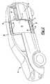
- FIG. 6is a partial perspective view of the vehicle of FIG. 1 showing the sliding-side door assembly in an open state and a track assembly in a fully extended and pivoted state;
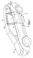
- FIG. 7is a partial perspective view of the vehicle of FIG. 1 showing the sliding-side door assembly in an open state and a track assembly in a pivoted and extended state;
- FIG. 8is a perspective view of a vehicle incorporating a sliding-side door assembly in accordance with the principles of the present disclosure
- FIG. 9is a partial perspective view of the vehicle of FIG. 8 showing the sliding-side door assembly initially moving from a closed state to an open state;
- FIG. 10is a partial, top perspective view of the vehicle of FIG. 8 showing the sliding-side door assembly initially moving from a closed state to an open state;
- FIG. 11is a partial perspective view of the vehicle of FIG. 8 showing the sliding-side door assembly moving from a closed state to an open state;
- FIG. 12is a partial, top perspective view of the vehicle of FIG. 8 showing the sliding-side door assembly moving from a closed state to an open state;
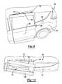
- FIG. 13is a partial perspective view of the vehicle of FIG. 8 showing the sliding-side door assembly in an open state
- FIG. 14is a partial, top perspective view of the vehicle of FIG. 8 showing the sliding-side door assembly in an open state;
- FIG. 16is a partial perspective view of the vehicle of FIG. 8 showing the track assembly of FIG. 15 in a pivoted state;
- FIG. 17is a partial perspective view of the vehicle of FIG. 8 showing the track assembly of FIG. 15 in a pivoted and partially extended state;
- FIG. 18is a partial perspective view of the vehicle of FIG. 8 showing the track assembly of FIG. 15 in a pivoted and fully extended state.
- a vehicle 10is provided.
- the vehicle 10includes a side-door assembly 12 that may be selectively moved relative to an opening 14 of the vehicle 10 between a closed state ( FIG. 1 ) and an open state ( FIG. 2 ).
- a closed stateFIG. 1
- an open stateFIG. 2
- the side-door assembly 12When the side-door assembly 12 is in the open state, access to a passenger compartment 16 of the vehicle 10 is permitted generally via the opening 14 .
- the side-door assembly 12is shown to include a closure panel or side door 18 , an upper track assembly 20 , a lower track assembly 22 , and a mid-track assembly 24 .
- the side door 18may be moved relative to a rear-quarter panel 26 of the vehicle 10 between a closed state ( FIG. 1 ), preventing access to the passenger compartment 16 via the opening 14 , and an open state ( FIG. 2 ), permitting access to the passenger compartment 16 via the opening 14 .
- the side door 18may include a series of rollers that are respectively received within the upper track assembly 20 , lower track assembly 22 , and mid-track assembly 24 to permit slideable movement of the side door 18 relative to the rear-quarter panel 26 when the side door 18 is moved between the open state and the closed state.
- the upper track assembly 20may be located proximate to a roof panel 28 and may include a channel 30 that receives a roller (not shown) associated with the side door 18 .
- the rollers of the side door 18may be received within the channel 30 and may concurrently serve to position and support the side door 18 throughout a range-of-motion of the side door 18 relative to the rear-quarter panel 26 .
- the rollersmay follow the general shape of the channel 30 and, thus, not only aid in supporting the side door 18 relative to the rear-quarter panel 26 but, also, position the side door 18 in a desired location relative to the rear-quarter panel 26 throughout a range-of-motion of the side door 18 relative to the rear-quarter panel 26 as the side door 18 is moved between the closed state and the open state.
- the lower track assembly 22is disposed proximate to a sill 32 of the vehicle 10 and may include a channel 34 . As with the upper track assembly 20 , the lower track assembly 22 may also receive rollers (not shown) associated with the side door 18 that are disposed generally within the channel 34 .
- the channel 34cooperates with the rollers to position and support the side door 18 throughout a range-of-motion of the side door 18 relative to the rear-quarter panel 26 . Specifically, the rollers move within the channel 34 and generally move along a direction defined by the overall shape and configuration of the channel 34 .
- the mid-track assembly 24is disposed generally between the upper track assembly 20 and the lower track assembly 22 and may extend into the rear-quarter panel 26 .
- the mid-track assembly 24may include a first track portion 36 , a second track portion 38 , a ramp 40 , and a biasing member 42 .
- the first track portion 36may be pivotably supported at a first end 44 relative to the rear-quarter panel 26 and may slidably receive the second track portion 38 within a channel 46 ( FIG. 6 ).
- the second track portion 38may be slidably received within the channel 46 of the first track portion 36 such that the second track portion 38 is in a telescoping relationship with the first track portion 36 and may be moved between a retracted state ( FIGS. 3 and 4 ) and an extended state ( FIGS. 5 and 6 ).
- the second track portion 38may include a channel 48 as well as a distal end 50 defining a stop 52 .
- the channel 48may receive at least one roller 54 therein that is rotatably attached to the side door 18 via a bracket 56 .
- the roller 54is rotatable relative to the bracket 56 and therefore permits movement of the door 18 and bracket 56 relative to the channel 48 as the door 18 is moved between the open state and the closed state.
- the bracket 56serves to support the door 18 relative to the second track portion 38 and also properly spaces the side door 18 a predetermined distance away from an outer surface 58 of the rear-quarter panel 26 when the side door 18 moves from the closed state to the open state.
- the biasing member 42may be a coil spring ( FIG. 7 ) and may be disposed between the first track portion 36 and the rear-quarter panel 26 .
- the biasing member 42may apply a force on the first track portion 36 to bias the first track portion 36 in a direction generally toward the rear-quarter panel 26 .
- Movement of the first track portion 36 and second track portion 38 in the direction (Y) against the force exerted on the first track portion 36 by the biasing member 42causes the first track portion 36 and second track portion 38 to move sufficiently away from the rear-quarter panel 26 such that the second track portion 38 is permitted to slide relative to the first track portion 36 .
- Movement of the second track portion 38 relative to the first track portion 36is accomplished by the roller 54 contacting the stop 52 of the distal end 50 of the second track portion 38 , thereby applying a force on the second track portion 38 and causing the second track portion 38 to telescope from the first track portion 36 .
- the second track portion 38continues to move relative to the first track portion 36 until the second track portion 38 contacts a stop 64 ( FIG. 5 ) of the first track portion 36 .
- a stop 64FIG. 5
- Contact between the second track portion 38 and the stop 64 of the first track portion 36prevents further movement of the second track portion 38 relative to the first track portion 36 .
- the side door 18is in the fully open position, as shown in FIG. 2 .
- a forcemay be applied to the side door 18 to move the side door from the open state to the closed state by applying a force in a direction opposite to direction (X). Movement of the side door 18 causes the roller 54 to move within the second track portion 38 and causes the second track portion 38 to move relative to the first track portion 36 and telescope into the channel 46 of the first track portion 36 .
- the biasing member 42is permitted to move the first track portion 36 and second track portion 38 relative to the rear-quarter panel 26 in a direction substantially opposite to direction (Y).
- the foregoing operation of the side-door assembly 12is described as requiring a force to be applied to the side door 18 to move the side door 18 between the closed state and the open state.
- the forcemay be manually applied to the side door 18 or may be applied to the side door 18 via a powered system (not shown).
- a vehicle 100 incorporating a side-door assembly 102is provided.
- the side-door assembly 102is movable between a closed state (solid lines in FIG. 8 ) and an open state (dashed lines in FIG. 8 ), whereby the side-door assembly 102 closes an opening 104 of the vehicle 100 in the closed state and permits access to a passenger compartment 106 via the opening 104 in the open state.
- the side-door assembly 102may include a closure panel or side door 108 , an upper track assembly 110 , a lower track assembly 112 , and an actuation mechanism 114 .
- the side door 108is translatable relative to the vehicle 100 in a direction (Z), as shown in FIG. 8 , to allow the side door 108 to move between the closed state and the open state. Movement of the side door 108 relative to a rear-quarter panel 116 of the vehicle 100 is dictated and controlled by the upper track assembly 110 and the lower track assembly 112 .
- the upper track assembly 110may include a channel 118 ( FIG. 13 ) that receives a series of rollers (none shown) associated with the side door 108 . Engagement between the rollers of the side door 108 and the channel 118 of the upper track assembly 110 allows the side door 108 to move relative to and within the channel 118 of the upper track assembly 110 and, thus, allows the side door 108 to translate substantially in the direction (Z) relative to the rear-quarter panel 116 .
- the upper track assembly 110 and, thus, the channel 118may include a substantially arcuate shape to allow the side door 108 to concurrently slide relative to and move away from an outer surface 120 of the rear-quarter panel 116 when the side door 108 is initially moved from the closed state to the open state to allow the side door 108 to be spaced apart from the rear-quarter panel 116 when the side door 108 moves into the open state.
- engagement between the rollers of the side door 108 and the channel 118also permits the side door 108 to pivot about the rollers to allow the side door 108 to tilt during movement of the side door 108 between the open state and the closed state. Permitting the side door 108 to tilt during movement of the side door 108 between the open state and the closed state allows a bottom portion of the side door 108 proximate to the lower track assembly 112 to move further away from the rear-quarter panel 116 while concurrently retaining the rollers within the channel 118 of the upper track assembly 110 .
- the lower track assembly 112may include a first track portion 122 , a second track portion 124 , and a third track portion 126 .
- the first track portion 122 , second track portion 124 , and third track portion 126may be in a telescoping relationship to one another such that the first track portion 122 is received within the second track portion 124 and the second track portion 124 is received within the third track portion 126 when the side door 108 is in the closed state.
- the first track portion 122may be pivotably mounted to the vehicle 100 proximate to a sill 128 of the vehicle 100 at a first end 130 of the first track portion 122 .
- the first end 130may be directly and pivotably attached to the sill 128 or, alternatively, may include a link (not shown) that concurrently permits the first end 130 of the first track portion 122 to both pivot relative to the sill 128 and move generally away from the sill in a direction (Q) shown in FIG. 15 . Allowing the first track portion 122 to move in the direction (Q) and concurrently pivot about the first end 130 relative to the sill 128 allows the side door 108 to sufficiently move away from a front door 132 of the vehicle 100 such that sufficient clearance is provided between the side door 108 and the front door 132 to permit independent operation of the side door 108 and front door 132 .
- the second track portion 124may include a channel 134 ( FIG. 16 ) that slidably receives the first track portion 122 therein when the side door 108 is in the closed state.
- the third track portion 126may include a channel 136 that slidably receives the second track portion 124 therein when the side door 108 is in the closed state. Allowing the first track portion 122 to be slidably received within the channel 134 of the second track portion 124 and allowing the second track portion 124 to be slidably received within the channel 136 of the third track portion 126 allows the first track portion 122 , second track portion 124 , and third track portion 126 to move from a retracted state ( FIG. 16 ) to an extended state ( FIG. 18 ) when the side door 108 is moved from the closed state to the open state ( FIG. 8 ) relative to the rear-quarter panel 116 of the vehicle 100 .
- the third track portion 126may be pivotably attached to a bottom portion of the side door 108 such that the side door 108 is fixed for movement with the third track portion 126 in the direction (Z) shown in FIG. 1 when the side door 108 is moved between the closed state and the open state. While the side door 108 is described as being fixed for movement with the third track portion 126 in the direction (Z), the side door 108 may also be pivotably attached to the third track portion 126 to allow the side door 108 to pivot relative to the third track portion 126 when the third track portion 126 telescopes away from the first track portion 122 and second track portion 124 and generally away from the outer surface 120 of the rear-quarter panel 116 .
- the first track portion 122 , second track portion 124 , and third track portion 126must pivot about the first end 130 of the first track portion 122 when the side door 108 is initially moved from the closed state to the open state to provide sufficient clearance between the second track portion 124 and third track portion 126 when the side door 108 is moved in the direction (Z) relative to the rear-quarter panel 116 to prevent contact between the side door 108 and either track portion 124 , 126 and the outer surface 120 of the rear-quarter panel 116 .
- the side door 108may be required to pivot relative to the third track portion 126 to allow a top portion of the side door 108 proximate to the upper track assembly 110 to remain in close proximity to and within the channel 118 of the upper track assembly 110 while concurrently allowing the bottom portion of the side door 108 disposed proximate and attached to the third track portion 126 to concurrently move away from the outer surface 120 of the rear-quarter panel 116 .
- the actuation mechanism 114is shown to include a first link 138 and a second link 140 .
- the first link 138may be pivotably attached proximate to the sill 128 of the vehicle at a first end and may be pivotably attached to the second link 140 at a second end.
- the second link 140may be pivotably attached to the first link 138 at a first end and may be pivotably attached to the first track portion 122 at a second end.
- the actuation mechanism 114may be movable between an unlocked state when the side door 108 is in the closed state and a locked state when the side door 108 is moving from the closed state to the open state and also when the side door 108 is in the open state.
- the first link 138 and second link 140may cooperate with the first end 130 and associated link (not shown) of the first end 130 to provide the first track portion 122 and, thus, the second track portion 124 and third track portion 126 with a four-bar linkage that permits the first track portion 122 , second track portion 124 , and third track portion 126 to both pivot and move away from the sill 128 when the side door 108 is initially moved from the closed state to the open state.
- an eccentric cammay be disposed proximate to the first end 130 of the first track portion 122 to provide the first track portion 122 with the ability to concurrently move away from the sill 128 and pivot about the first end 132 .
- Such movement of the side door 108provides for sufficient clearance between the side door 108 and the front door 132 , thereby permitting the side door 108 and front door 132 to operate independently from one another.
- a forcemay be applied to the side door 108 of the side-door assembly 102 by either applying a manual force to the side door 108 or by actuating a power system (not shown) associated with the side-door assembly 102 to move the side door 108 from the closed state toward the open state.
- Applying a force to the side door 108causes the side door 108 to concurrently pivot about the first end 130 of the first track portion 122 and to move in the direction (Q) shown in FIG. 15 .
- the first track portion 122continues to move in the direction (Q) and to pivot about the first end ( 130 ) until the first link 138 and the second link 140 are in the locked state.
- the second track portion 124is permitted to translate relative to the first track portion 122 in the direction (Z) shown in FIG. 8 , thereby allowing the side door 108 to move in the direction (Z).
- the third track portion 126may telescope from the second track portion 124 and continue movement along the direction (Z) until the side door 108 is in the fully open position ( FIG. 13 ).
- the first track portion 122is exposed and may provide a step surface 142 that facilitates entry of a passenger into the passenger compartment 106 .
- first link 138 and second link 140remain in the locked state when the side door 108 moves relative to the rear-quarter panel 116 in the direction (Z) to provide stability and support to the side door 108 as the side door 108 moves in the direction (Z).
- a forcemay be applied to the side door 108 in a direction substantially opposite to direction (Z) to move the side door 108 from the open state toward the closed state. Movement of the side door 108 in the direction opposite to direction (Z) causes the third track portion 126 to once again slidably receive the second track portion 124 therein and causes the second track portion 124 to slidably receive the first track portion 122 therein until the first track portion 122 and second track portion 124 are received within the third track portion 126 ( FIG. 15 ).
- first link 138 and the second link 140 of the actuation mechanism 114may be moved from the locked state to the unlocked state, thereby causing the first track portion 122 to both pivot about the first end 130 and move generally toward the sill 128 in a direction substantially opposite to direction (Q).
- first track portion 122 , second track portion 124 , and third track portion 126are disposed adjacent to the sill 128 , the side door 108 is returned to the closed state and access to the passenger compartment 106 via the opening 104 is prevented until the side door 108 is once again moved from the closed state to the open state.
Landscapes
- Engineering & Computer Science (AREA)
- Mechanical Engineering (AREA)
- Support Devices For Sliding Doors (AREA)
Abstract
Description
Claims (20)
Priority Applications (1)
| Application Number | Priority Date | Filing Date | Title |
|---|---|---|---|
| US13/356,682US8794688B2 (en) | 2012-01-24 | 2012-01-24 | Door assembly for a vehicle |
Applications Claiming Priority (1)
| Application Number | Priority Date | Filing Date | Title |
|---|---|---|---|
| US13/356,682US8794688B2 (en) | 2012-01-24 | 2012-01-24 | Door assembly for a vehicle |
Publications (2)
| Publication Number | Publication Date |
|---|---|
| US20130186002A1 US20130186002A1 (en) | 2013-07-25 |
| US8794688B2true US8794688B2 (en) | 2014-08-05 |
Family
ID=48796051
Family Applications (1)
| Application Number | Title | Priority Date | Filing Date |
|---|---|---|---|
| US13/356,682Active2032-03-01US8794688B2 (en) | 2012-01-24 | 2012-01-24 | Door assembly for a vehicle |
Country Status (1)
| Country | Link |
|---|---|
| US (1) | US8794688B2 (en) |
Cited By (4)
| Publication number | Priority date | Publication date | Assignee | Title |
|---|---|---|---|---|
| US10017978B2 (en)* | 2016-03-16 | 2018-07-10 | Honda Motor Co., Ltd. | Methods and apparatus for overriding powered vehicle door |
| US10480233B2 (en)* | 2016-12-16 | 2019-11-19 | Ford Global Technologies, Llc | Hidden sliding door assembly for a motor vehicle |
| US10556492B2 (en)* | 2017-11-10 | 2020-02-11 | Deere & Company | Operator cab with segmented door |
| US11332081B2 (en)* | 2018-12-12 | 2022-05-17 | Hyundai Motor Company | Structure of a sliding trim cover for opposite sliding doors |
Families Citing this family (2)
| Publication number | Priority date | Publication date | Assignee | Title |
|---|---|---|---|---|
| KR101542981B1 (en)* | 2013-12-27 | 2015-08-07 | 현대자동차 주식회사 | Front door device of vehicle |
| KR102681712B1 (en)* | 2019-11-12 | 2024-07-05 | 현대자동차주식회사 | Link mechanism for vehicle door and vehicle door opening and closing apparatus having the same |
Citations (63)
| Publication number | Priority date | Publication date | Assignee | Title |
|---|---|---|---|---|
| US4152872A (en)* | 1977-01-12 | 1979-05-08 | Nissan Motor Company, Limited | Sliding mechanism for vehicle sliding door |
| US5316365A (en)* | 1993-01-25 | 1994-05-31 | General Motors Corporation | Sliding door closed loop cable closure system with balanced cable tension and varying diameter pulleys |
| US5361540A (en)* | 1993-09-29 | 1994-11-08 | General Motors Corporation | Door check for vehicle sliding door |
| US5454618A (en)* | 1994-09-02 | 1995-10-03 | Ford Motor Company | Automotive sliding door stop for fuel filler access lid |
| US5481830A (en)* | 1994-03-04 | 1996-01-09 | General Motors Corporation | Door check for vehicle sliding door |
| US5536061A (en)* | 1994-12-05 | 1996-07-16 | Chrysler Corporation | Automotive vehicle body with powered sliding side door |
| US5618080A (en)* | 1993-12-27 | 1997-04-08 | Ford Motor Company | Upper track roller mechanism for sliding door |
| US5896704A (en) | 1996-08-19 | 1999-04-27 | Daimlerchrysler Corporation | Track arrangement for vehicle sliding door |
| US5927789A (en)* | 1998-11-02 | 1999-07-27 | Ford Global Technologies, Inc. | Seat assembly |
| US6007141A (en)* | 1996-06-10 | 1999-12-28 | General Motors Corporation | Fuel door interlock for vehicle sliding door |
| US6087794A (en)* | 1997-01-30 | 2000-07-11 | Ohi Seisakusho Co., Ltd. | Automatic open-and-close system for a vehicle slide door |
| US6134837A (en)* | 1997-01-07 | 2000-10-24 | Ohi Seisakusho Co., Ltd. | Door holding control system for a vehicle slide door |
| US6164015A (en)* | 1995-10-02 | 2000-12-26 | Ohi Seisakusho Co., Ltd. | Device for automatically controlling opening and closing of a vehicle slide door |
| US6279267B1 (en)* | 1999-08-11 | 2001-08-28 | Ford Global Tech., Inc. | Vehicle door assembly |
| US6328374B1 (en)* | 2000-06-21 | 2001-12-11 | Ford Global Technologies, Inc. | Fully-openable slidable vehicle door assembly |
| US6386621B1 (en)* | 2001-08-08 | 2002-05-14 | Ford Global Technologies, Inc. | Reverse opening vehicle door |
| US6515229B2 (en)* | 2000-06-30 | 2003-02-04 | Yazaki Corporation | Structure of installing wire harness for sliding door |
| US6553719B1 (en)* | 2000-10-13 | 2003-04-29 | Hi-Lex Corporation | Door mounted power sliding door mechanism |
| US6588829B2 (en)* | 1999-12-21 | 2003-07-08 | Daimlerchrysler Corporation | Method for operating a vehicle power sliding door |
| US6637803B2 (en)* | 2001-06-27 | 2003-10-28 | Wagon Automotice Snc | Motor vehicle door drive mechanism, with corresponding door, carriage and vehicle |
| US6669266B1 (en)* | 2003-01-15 | 2003-12-30 | The Braun Corporation | Door assembly for improved vehicle access |
| US6781058B1 (en)* | 2003-02-20 | 2004-08-24 | Stoneridge Inc., Alphabet Division | Cable guide assembly for a vehicle sliding door |
| US6840567B2 (en)* | 2002-07-31 | 2005-01-11 | Mazda Motor Corporation | Sliding door structure for vehicle |
| US6851743B2 (en)* | 2002-05-01 | 2005-02-08 | Toto Tech, Inc. | Slide mechanism for door and structural member assembly |
| US6860543B2 (en)* | 2002-05-01 | 2005-03-01 | Toto Tech, Inc. | Mechanism for moving a door |
| US6932417B2 (en)* | 2003-09-23 | 2005-08-23 | Gecom Corporation | Vehicle sliding door with extended travel |
| US6962383B2 (en)* | 2001-02-20 | 2005-11-08 | Araco Kabushiki Kaisha | Vehicle seat |
| US6971706B2 (en)* | 2003-03-25 | 2005-12-06 | Mazda Motor Corporation | Side structure of a vehicle |
| US20060151231A1 (en)* | 2002-08-23 | 2006-07-13 | Thomas Bucksch | Motor vehicle comprising a device for controlling the shifting movement of a closure element |
| US7104588B2 (en)* | 2002-05-01 | 2006-09-12 | Toto Tech, Inc | Mechanism for moving a door |
| US20060225358A1 (en)* | 2005-04-11 | 2006-10-12 | Haag Ronald H | Apparatus and method for providing a drive device for a vehicle door |
| US7144068B2 (en)* | 2003-11-20 | 2006-12-05 | Intier Automotive Closures Inc. | Drive mechanism for selectively opening and closing a closure panel manually or automatically |
| US7243978B2 (en)* | 2005-10-18 | 2007-07-17 | Daimlerchrysler Corporation | Door assembly for a vehicle |
| US7243461B2 (en)* | 2003-03-19 | 2007-07-17 | Rogers Jr Lloyd W | Hinge mechanism for a sliding door |
| US7322636B1 (en)* | 2007-01-05 | 2008-01-29 | Ford Global Technologies, Llc | Vehicle side-entry door assembly |
| US7325361B2 (en)* | 2003-03-19 | 2008-02-05 | Delphi Technologies, Inc. | Apparatus and method for providing a modular sliding door mechanism |
| US20080072497A1 (en)* | 2006-09-25 | 2008-03-27 | Peter Lance Oxley | Belt-Driven Rack Gear Power Sliding Door |
| US7390054B2 (en)* | 2004-09-03 | 2008-06-24 | Fuji Jukogyo Kabushiki Kaisha | Vehicle slide door apparatus |
| US7422268B2 (en)* | 2005-10-28 | 2008-09-09 | Brose Schliesssyteme Gmbh & Co., Kg | Sliding door arrangement for a motor vehicle |
| US7520557B2 (en)* | 2004-07-02 | 2009-04-21 | Mazda Motor Corporation | Side structure of vehicle |
| US7549251B2 (en)* | 2003-01-21 | 2009-06-23 | Knorr-Bremse Ges.M.B.H. | Pivoting sliding doors for vehicles |
| US20090189412A1 (en)* | 2008-01-29 | 2009-07-30 | Nissan Design America, Inc. | Sliding door system |
| US20090199480A1 (en)* | 2008-02-08 | 2009-08-13 | Gm Global Technology Operations, Inc. | Cover for guide parts of a motor vehicle sliding door |
| US20090230724A1 (en)* | 2008-03-11 | 2009-09-17 | Gm Global Technology Operations, Inc. | Vehicle Sliding Door Travel Extension System |
| US20090230722A1 (en)* | 2008-03-11 | 2009-09-17 | Gm Global Technology Operations, Inc. | Extended-Travel Sliding Door with Articulating Roller Bracket |
| US7621586B2 (en)* | 2008-04-25 | 2009-11-24 | Gm Global Technology Operations, Inc. | Sliding door roller bracket track extension with interlock |
| US7647728B2 (en)* | 2003-04-09 | 2010-01-19 | Bortoluzzi Mobili S.R.L. | Sliding doors with cam guides for coplanar closing, particularly for pieces of furniture or similars |
| US7703242B2 (en)* | 2003-09-20 | 2010-04-27 | Edscha Ag | Guiding system for a sliding door |
| US20100154313A1 (en)* | 2008-12-18 | 2010-06-24 | Adrian Nicholas Alexander Elliott | Dual action power drive unit for a vehicle door |
| US20100295337A1 (en)* | 2009-05-22 | 2010-11-25 | Adrian Elliott | Simultaneous single rail movement system for a vehicle door ii |
| US7950109B2 (en)* | 2007-09-14 | 2011-05-31 | Ford Global Technologies, Llc | Vehicle 180 degree rear door articulating mechanism |
| US7950719B2 (en)* | 2007-09-14 | 2011-05-31 | Ford Global Technologies, Llc | Vehicle dual hinge rear door articulating and sliding system |
| US7977903B2 (en)* | 2008-03-13 | 2011-07-12 | Mitsui Mining & Smelting Co., Ltd. | Electrically powered door actuating system of motor vehicle |
| US8007028B2 (en)* | 2009-07-31 | 2011-08-30 | Nissan North America, Inc. | Vehicle sliding door structure |
| US8020923B2 (en)* | 2008-08-25 | 2011-09-20 | GM Global Technology Operations LLC | Motor vehicle with a sliding door and an adjustable armrest |
| US8070102B2 (en)* | 2008-08-01 | 2011-12-06 | Honda Motor Co., Ltd. | Slide door device for aircraft |
| US8234816B2 (en)* | 2005-02-04 | 2012-08-07 | Dura Automotive Plettenberg Entwicklungs-Und Vertreibs Gmbh | Door for a motor vehicle |
| US8303028B2 (en)* | 2011-01-21 | 2012-11-06 | Nissan North America, Inc. | Slide rail force distribution member |
| US8353555B2 (en)* | 2010-08-06 | 2013-01-15 | Honda Motor Co., Ltd. | Link-type sliding door mechanism |
| US8413379B2 (en)* | 2009-11-20 | 2013-04-09 | Aisin Seiki Kabushiki Kaisha | Step unit |
| US8464469B2 (en)* | 2007-03-21 | 2013-06-18 | Magna Closures Inc. | Belt driven power sliding door with belt tensioner |
| US8469437B2 (en)* | 2008-09-19 | 2013-06-25 | Ship-Car S.r.l. Societá a Socio Unico | Movement device and assembly |
| US8596710B2 (en)* | 2012-02-09 | 2013-12-03 | Chrysler Group Llc | Sliding door system |
- 2012
- 2012-01-24USUS13/356,682patent/US8794688B2/enactiveActive
Patent Citations (65)
| Publication number | Priority date | Publication date | Assignee | Title |
|---|---|---|---|---|
| US4152872A (en)* | 1977-01-12 | 1979-05-08 | Nissan Motor Company, Limited | Sliding mechanism for vehicle sliding door |
| US5316365A (en)* | 1993-01-25 | 1994-05-31 | General Motors Corporation | Sliding door closed loop cable closure system with balanced cable tension and varying diameter pulleys |
| US5361540A (en)* | 1993-09-29 | 1994-11-08 | General Motors Corporation | Door check for vehicle sliding door |
| US5618080A (en)* | 1993-12-27 | 1997-04-08 | Ford Motor Company | Upper track roller mechanism for sliding door |
| US5481830A (en)* | 1994-03-04 | 1996-01-09 | General Motors Corporation | Door check for vehicle sliding door |
| US5454618A (en)* | 1994-09-02 | 1995-10-03 | Ford Motor Company | Automotive sliding door stop for fuel filler access lid |
| US5536061A (en)* | 1994-12-05 | 1996-07-16 | Chrysler Corporation | Automotive vehicle body with powered sliding side door |
| US6164015A (en)* | 1995-10-02 | 2000-12-26 | Ohi Seisakusho Co., Ltd. | Device for automatically controlling opening and closing of a vehicle slide door |
| US7073291B2 (en)* | 1995-10-02 | 2006-07-11 | Ohi Seisakusho Co., Ltd. | Device for automatically controlling opening and closing of a vehicle slide door |
| US6007141A (en)* | 1996-06-10 | 1999-12-28 | General Motors Corporation | Fuel door interlock for vehicle sliding door |
| US5896704A (en) | 1996-08-19 | 1999-04-27 | Daimlerchrysler Corporation | Track arrangement for vehicle sliding door |
| US6134837A (en)* | 1997-01-07 | 2000-10-24 | Ohi Seisakusho Co., Ltd. | Door holding control system for a vehicle slide door |
| US6087794A (en)* | 1997-01-30 | 2000-07-11 | Ohi Seisakusho Co., Ltd. | Automatic open-and-close system for a vehicle slide door |
| US5927789A (en)* | 1998-11-02 | 1999-07-27 | Ford Global Technologies, Inc. | Seat assembly |
| US6279267B1 (en)* | 1999-08-11 | 2001-08-28 | Ford Global Tech., Inc. | Vehicle door assembly |
| US6588829B2 (en)* | 1999-12-21 | 2003-07-08 | Daimlerchrysler Corporation | Method for operating a vehicle power sliding door |
| US6328374B1 (en)* | 2000-06-21 | 2001-12-11 | Ford Global Technologies, Inc. | Fully-openable slidable vehicle door assembly |
| US6515229B2 (en)* | 2000-06-30 | 2003-02-04 | Yazaki Corporation | Structure of installing wire harness for sliding door |
| US6553719B1 (en)* | 2000-10-13 | 2003-04-29 | Hi-Lex Corporation | Door mounted power sliding door mechanism |
| US6962383B2 (en)* | 2001-02-20 | 2005-11-08 | Araco Kabushiki Kaisha | Vehicle seat |
| US6637803B2 (en)* | 2001-06-27 | 2003-10-28 | Wagon Automotice Snc | Motor vehicle door drive mechanism, with corresponding door, carriage and vehicle |
| US6386621B1 (en)* | 2001-08-08 | 2002-05-14 | Ford Global Technologies, Inc. | Reverse opening vehicle door |
| US7104588B2 (en)* | 2002-05-01 | 2006-09-12 | Toto Tech, Inc | Mechanism for moving a door |
| US6851743B2 (en)* | 2002-05-01 | 2005-02-08 | Toto Tech, Inc. | Slide mechanism for door and structural member assembly |
| US6860543B2 (en)* | 2002-05-01 | 2005-03-01 | Toto Tech, Inc. | Mechanism for moving a door |
| US6840567B2 (en)* | 2002-07-31 | 2005-01-11 | Mazda Motor Corporation | Sliding door structure for vehicle |
| US20060151231A1 (en)* | 2002-08-23 | 2006-07-13 | Thomas Bucksch | Motor vehicle comprising a device for controlling the shifting movement of a closure element |
| US6669266B1 (en)* | 2003-01-15 | 2003-12-30 | The Braun Corporation | Door assembly for improved vehicle access |
| US7549251B2 (en)* | 2003-01-21 | 2009-06-23 | Knorr-Bremse Ges.M.B.H. | Pivoting sliding doors for vehicles |
| US6781058B1 (en)* | 2003-02-20 | 2004-08-24 | Stoneridge Inc., Alphabet Division | Cable guide assembly for a vehicle sliding door |
| US7243461B2 (en)* | 2003-03-19 | 2007-07-17 | Rogers Jr Lloyd W | Hinge mechanism for a sliding door |
| US7325361B2 (en)* | 2003-03-19 | 2008-02-05 | Delphi Technologies, Inc. | Apparatus and method for providing a modular sliding door mechanism |
| US6971706B2 (en)* | 2003-03-25 | 2005-12-06 | Mazda Motor Corporation | Side structure of a vehicle |
| US7647728B2 (en)* | 2003-04-09 | 2010-01-19 | Bortoluzzi Mobili S.R.L. | Sliding doors with cam guides for coplanar closing, particularly for pieces of furniture or similars |
| US7703242B2 (en)* | 2003-09-20 | 2010-04-27 | Edscha Ag | Guiding system for a sliding door |
| US6932417B2 (en)* | 2003-09-23 | 2005-08-23 | Gecom Corporation | Vehicle sliding door with extended travel |
| US7144068B2 (en)* | 2003-11-20 | 2006-12-05 | Intier Automotive Closures Inc. | Drive mechanism for selectively opening and closing a closure panel manually or automatically |
| US7520557B2 (en)* | 2004-07-02 | 2009-04-21 | Mazda Motor Corporation | Side structure of vehicle |
| US7390054B2 (en)* | 2004-09-03 | 2008-06-24 | Fuji Jukogyo Kabushiki Kaisha | Vehicle slide door apparatus |
| US8234816B2 (en)* | 2005-02-04 | 2012-08-07 | Dura Automotive Plettenberg Entwicklungs-Und Vertreibs Gmbh | Door for a motor vehicle |
| US20060225358A1 (en)* | 2005-04-11 | 2006-10-12 | Haag Ronald H | Apparatus and method for providing a drive device for a vehicle door |
| US7243978B2 (en)* | 2005-10-18 | 2007-07-17 | Daimlerchrysler Corporation | Door assembly for a vehicle |
| US7422268B2 (en)* | 2005-10-28 | 2008-09-09 | Brose Schliesssyteme Gmbh & Co., Kg | Sliding door arrangement for a motor vehicle |
| US20080072497A1 (en)* | 2006-09-25 | 2008-03-27 | Peter Lance Oxley | Belt-Driven Rack Gear Power Sliding Door |
| US7322636B1 (en)* | 2007-01-05 | 2008-01-29 | Ford Global Technologies, Llc | Vehicle side-entry door assembly |
| US8464469B2 (en)* | 2007-03-21 | 2013-06-18 | Magna Closures Inc. | Belt driven power sliding door with belt tensioner |
| US7950719B2 (en)* | 2007-09-14 | 2011-05-31 | Ford Global Technologies, Llc | Vehicle dual hinge rear door articulating and sliding system |
| US7950109B2 (en)* | 2007-09-14 | 2011-05-31 | Ford Global Technologies, Llc | Vehicle 180 degree rear door articulating mechanism |
| US7717493B2 (en)* | 2008-01-29 | 2010-05-18 | Nissan Design America, Inc. | Sliding door system |
| US20090189412A1 (en)* | 2008-01-29 | 2009-07-30 | Nissan Design America, Inc. | Sliding door system |
| US20090199480A1 (en)* | 2008-02-08 | 2009-08-13 | Gm Global Technology Operations, Inc. | Cover for guide parts of a motor vehicle sliding door |
| US20090230722A1 (en)* | 2008-03-11 | 2009-09-17 | Gm Global Technology Operations, Inc. | Extended-Travel Sliding Door with Articulating Roller Bracket |
| US20090230724A1 (en)* | 2008-03-11 | 2009-09-17 | Gm Global Technology Operations, Inc. | Vehicle Sliding Door Travel Extension System |
| US7977903B2 (en)* | 2008-03-13 | 2011-07-12 | Mitsui Mining & Smelting Co., Ltd. | Electrically powered door actuating system of motor vehicle |
| US7621586B2 (en)* | 2008-04-25 | 2009-11-24 | Gm Global Technology Operations, Inc. | Sliding door roller bracket track extension with interlock |
| US8070102B2 (en)* | 2008-08-01 | 2011-12-06 | Honda Motor Co., Ltd. | Slide door device for aircraft |
| US8020923B2 (en)* | 2008-08-25 | 2011-09-20 | GM Global Technology Operations LLC | Motor vehicle with a sliding door and an adjustable armrest |
| US8469437B2 (en)* | 2008-09-19 | 2013-06-25 | Ship-Car S.r.l. Societá a Socio Unico | Movement device and assembly |
| US20100154313A1 (en)* | 2008-12-18 | 2010-06-24 | Adrian Nicholas Alexander Elliott | Dual action power drive unit for a vehicle door |
| US20100295337A1 (en)* | 2009-05-22 | 2010-11-25 | Adrian Elliott | Simultaneous single rail movement system for a vehicle door ii |
| US8007028B2 (en)* | 2009-07-31 | 2011-08-30 | Nissan North America, Inc. | Vehicle sliding door structure |
| US8413379B2 (en)* | 2009-11-20 | 2013-04-09 | Aisin Seiki Kabushiki Kaisha | Step unit |
| US8353555B2 (en)* | 2010-08-06 | 2013-01-15 | Honda Motor Co., Ltd. | Link-type sliding door mechanism |
| US8303028B2 (en)* | 2011-01-21 | 2012-11-06 | Nissan North America, Inc. | Slide rail force distribution member |
| US8596710B2 (en)* | 2012-02-09 | 2013-12-03 | Chrysler Group Llc | Sliding door system |
Cited By (4)
| Publication number | Priority date | Publication date | Assignee | Title |
|---|---|---|---|---|
| US10017978B2 (en)* | 2016-03-16 | 2018-07-10 | Honda Motor Co., Ltd. | Methods and apparatus for overriding powered vehicle door |
| US10480233B2 (en)* | 2016-12-16 | 2019-11-19 | Ford Global Technologies, Llc | Hidden sliding door assembly for a motor vehicle |
| US10556492B2 (en)* | 2017-11-10 | 2020-02-11 | Deere & Company | Operator cab with segmented door |
| US11332081B2 (en)* | 2018-12-12 | 2022-05-17 | Hyundai Motor Company | Structure of a sliding trim cover for opposite sliding doors |
Also Published As
| Publication number | Publication date |
|---|---|
| US20130186002A1 (en) | 2013-07-25 |
Similar Documents
| Publication | Publication Date | Title |
|---|---|---|
| US8794688B2 (en) | Door assembly for a vehicle | |
| US7641261B2 (en) | Extended travel sliding door mechanism | |
| US7798557B2 (en) | Vehicle unguided four-bar rear door articulating and sliding mechanism | |
| US7950719B2 (en) | Vehicle dual hinge rear door articulating and sliding system | |
| US6036257A (en) | Articulating lower roller assembly for sliding vehicle door | |
| US10337227B2 (en) | Rear access door latch and sealing systems | |
| US9506282B2 (en) | Tumble-home extending sliding door system | |
| US7918492B2 (en) | Vehicle door belt and cam articulating mechanism | |
| CA2862890C (en) | Sliding door system | |
| US8245447B2 (en) | Slide door assembly with safety device | |
| JP6064332B2 (en) | Sliding door device for vehicle | |
| US7621586B2 (en) | Sliding door roller bracket track extension with interlock | |
| US11002054B2 (en) | Sliding door mechanism | |
| US11066111B2 (en) | Articulating tailgate | |
| JP5644879B2 (en) | Vehicle door structure | |
| CN105587191B (en) | Axis latch system | |
| US11241997B2 (en) | Roof rack lighting system for a vehicle | |
| US20230340809A1 (en) | Vehicle Door Opening and Closing Apparatus | |
| JP2009114782A (en) | Sliding door structure for vehicles | |
| JP3742016B2 (en) | Sliding door device for vehicle | |
| US20220364400A1 (en) | Closure latch assembly with power cinch mechanism having anti-chucking function | |
| JP2007216782A (en) | Baggage transporting vehicle | |
| US20240110412A1 (en) | Sliding door device for vehicle | |
| JP4321183B2 (en) | Wheelchair loading / unloading device | |
| JP2024098579A (en) | Sliding door support mechanism |
Legal Events
| Date | Code | Title | Description |
|---|---|---|---|
| AS | Assignment | Owner name:CHRYSLER GROUP LLC, MICHIGAN Free format text:ASSIGNMENT OF ASSIGNORS INTEREST;ASSIGNORS:MATHER, CARL;TEASDALE, TODD;SIGNING DATES FROM 20120119 TO 20120123;REEL/FRAME:027580/0578 | |
| AS | Assignment | Owner name:JPMORGAN CHASE BANK, N.A., ILLINOIS Free format text:SECURITY AGREEMENT;ASSIGNOR:CHRYSLER GROUP LLC;REEL/FRAME:032384/0640 Effective date:20140207 Owner name:CITIBANK, N.A., NEW YORK Free format text:SECURITY AGREEMENT;ASSIGNOR:CHRYSLER GROUP LLC;REEL/FRAME:032384/0591 Effective date:20140207 Owner name:CITIBANK, N.A., NEW YORK Free format text:SECURITY AGREEMENT;ASSIGNOR:CHRYSLER GROUP LLC;REEL/FRAME:032384/0477 Effective date:20140207 | |
| STCF | Information on status: patent grant | Free format text:PATENTED CASE | |
| AS | Assignment | Owner name:FCA US LLC, MICHIGAN Free format text:CHANGE OF NAME;ASSIGNOR:CHRYSLER GROUP LLC;REEL/FRAME:035553/0356 Effective date:20141203 | |
| AS | Assignment | Owner name:FCA US LLC, FORMERLY KNOWN AS CHRYSLER GROUP LLC, Free format text:RELEASE OF SECURITY INTEREST RELEASING SECOND-LIEN SECURITY INTEREST PREVIOUSLY RECORDED AT REEL 026426 AND FRAME 0644, REEL 026435 AND FRAME 0652, AND REEL 032384 AND FRAME 0591;ASSIGNOR:CITIBANK, N.A.;REEL/FRAME:037784/0001 Effective date:20151221 | |
| AS | Assignment | Owner name:FCA US LLC (FORMERLY KNOWN AS CHRYSLER GROUP LLC), Free format text:RELEASE BY SECURED PARTY;ASSIGNOR:CITIBANK, N.A.;REEL/FRAME:042885/0255 Effective date:20170224 | |
| MAFP | Maintenance fee payment | Free format text:PAYMENT OF MAINTENANCE FEE, 4TH YEAR, LARGE ENTITY (ORIGINAL EVENT CODE: M1551) Year of fee payment:4 | |
| AS | Assignment | Owner name:FCA US LLC (FORMERLY KNOWN AS CHRYSLER GROUP LLC), Free format text:RELEASE BY SECURED PARTY;ASSIGNOR:JPMORGAN CHASE BANK, N.A.;REEL/FRAME:048177/0356 Effective date:20181113 | |
| MAFP | Maintenance fee payment | Free format text:PAYMENT OF MAINTENANCE FEE, 8TH YEAR, LARGE ENTITY (ORIGINAL EVENT CODE: M1552); ENTITY STATUS OF PATENT OWNER: LARGE ENTITY Year of fee payment:8 |