US8794489B2 - Dispensing valve - Google Patents
Dispensing valveDownload PDFInfo
- Publication number
- US8794489B2 US8794489B2US13/793,749US201313793749AUS8794489B2US 8794489 B2US8794489 B2US 8794489B2US 201313793749 AUS201313793749 AUS 201313793749AUS 8794489 B2US8794489 B2US 8794489B2
- Authority
- US
- United States
- Prior art keywords
- container
- annular wall
- opening
- valve
- dispensing
- Prior art date
- Legal status (The legal status is an assumption and is not a legal conclusion. Google has not performed a legal analysis and makes no representation as to the accuracy of the status listed.)
- Active
Links
Images


Classifications
- B—PERFORMING OPERATIONS; TRANSPORTING
- B65—CONVEYING; PACKING; STORING; HANDLING THIN OR FILAMENTARY MATERIAL
- B65D—CONTAINERS FOR STORAGE OR TRANSPORT OF ARTICLES OR MATERIALS, e.g. BAGS, BARRELS, BOTTLES, BOXES, CANS, CARTONS, CRATES, DRUMS, JARS, TANKS, HOPPERS, FORWARDING CONTAINERS; ACCESSORIES, CLOSURES, OR FITTINGS THEREFOR; PACKAGING ELEMENTS; PACKAGES
- B65D35/00—Pliable tubular containers adapted to be permanently or temporarily deformed to expel contents, e.g. collapsible tubes for toothpaste or other plastic or semi-liquid material; Holders therefor
- B65D35/44—Closures
- B65D35/46—Closures with valves
- B—PERFORMING OPERATIONS; TRANSPORTING
- B65—CONVEYING; PACKING; STORING; HANDLING THIN OR FILAMENTARY MATERIAL
- B65D—CONTAINERS FOR STORAGE OR TRANSPORT OF ARTICLES OR MATERIALS, e.g. BAGS, BARRELS, BOTTLES, BOXES, CANS, CARTONS, CRATES, DRUMS, JARS, TANKS, HOPPERS, FORWARDING CONTAINERS; ACCESSORIES, CLOSURES, OR FITTINGS THEREFOR; PACKAGING ELEMENTS; PACKAGES
- B65D47/00—Closures with filling and discharging, or with discharging, devices
- B65D47/04—Closures with discharging devices other than pumps
- B65D47/20—Closures with discharging devices other than pumps comprising hand-operated members for controlling discharge
- B65D47/2018—Closures with discharging devices other than pumps comprising hand-operated members for controlling discharge comprising a valve or like element which is opened or closed by deformation of the container or closure
- B65D47/2031—Closures with discharging devices other than pumps comprising hand-operated members for controlling discharge comprising a valve or like element which is opened or closed by deformation of the container or closure the element being formed by a slit, narrow opening or constrictable spout, the size of the outlet passage being able to be varied by increasing or decreasing the pressure
Definitions
- the present disclosureis directed to dispensing valves, to dispensing closures that include such valves, and to packages that include such closures.
- U.S. Pat. No. 6,672,487discloses a dispensing package for fluid products.
- a containerhas a body for holding a product to be dispensed and has a finish extending from the body with an open mouth.
- a closure baseincludes a ledge with a skirt externally secured to the finish and a cylindrical wall extending from the ledge coaxially with the mouth.
- a collarhas a deck with a central opening aligned with the mouth, a first cylindrical wall surrounding the opening and extending away from the mouth, and a second cylindrical wall externally surrounding and secured to the cylindrical wall on the base.
- a lidis integrally connected to the collar or the base by at least one hinge.
- a dispensing valve of flexible resilient elastomeric constructionhas a peripheral portion captured between the collar deck and the base cylindrical wall for securing the valve in position and simultaneously functioning as a seal between the base and the collar.
- the valvealso has an intermediate portion underlying the collar deck, and an annular wall portion extending from an inner end of the intermediate portion radially inwardly adjacent to an inner surface of the first cylindrical collar wall.
- the valvefurther has an inner portion extending radially inwardly from the annular wall portion, and at least one dispensing slit in the inner portion.
- U.S. Pat. No. 7,503,469discloses a dispensing valve that includes an annular ring of relatively rigid molded plastic construction, and a flexible resilient valve element integrally molded onto the ring, and the ring and the valve element have at least one mechanical interlock to secure the valve element to the ring as the valve element is molded onto the ring.
- the mechanical interlockincludes openings in an inner periphery of the annular ring and portions of the valve element molded into the openings.
- the inner periphery of the ringincludes an annular ledge, and the openings are through-openings disposed in an angularly spaced array around the ledge.
- Each of the openingsincludes an enlarged portion opening at one axially facing surface of the ledge and an ensmalled portion aligned with the enlarged portion and opening to a second axially facing surface of the ledge.
- One or more general objects of the present disclosureinclude providing a dispensing valve that is made of one piece and is not retained to a closure by a separate rigid retainer collar or mounting ring, may be recycled with a closure, may include a mounting portion and an opening portion flexibly coupled to the mounting portion by an isolating portion, and/or may have a vacuum break to reduce occurrences of valves sticking to one another and/or to material handling equipment during production.
- the present disclosureembodies a number of aspects that can be implemented separately from or in combination with each other.
- a dispensing valve in accordance with one aspect of the disclosureincludes a resiliently flexible mounting portion, a resiliently flexible opening portion disposed radially inwardly of the mounting portion, and a resiliently flexible isolating portion disposed radially between and coupled to the mounting and opening portions.
- the isolating portionextends both radially outwardly and axially to form a first radial space between the opening and isolating portions, and is spaced radially inwardly of the mounting portion to form a second radial space between the mounting and isolating portions.
- the opening portionmay include one or more slits.
- a dispensing valvein accordance with another aspect of the disclosure, includes a one-piece valve body of integrally formed plastic construction and of uniform plastic composition.
- the valve bodyincludes an radially outward annular portion including a radially inward leg and a radially outward leg configured for coupling to a valve mounting structure that at least radially outwardly surrounds the outward leg.
- the annular portionpreferably has a cross section of at least one of the following shapes: W-shape, X-shape, M-shape, V-shape, inverted V-shape, inverted U-shape, U-shape, or block U-shaped.
- the valve bodyalso includes a circular inward valve portion integrally and flexibly coupled to a free end of the inward leg of the annular portion, the inward valve portion having at least one slit.
- the cross section of the annular portionat least partially isolating the inward valve portion from stresses imparted to the dispensing valve.
- a dispensing assemblyincludes a dispensing structure having a dispensing passage and an annular wall, and a dispensing valve carried within the annular wall of the dispensing structure and in communication with the dispensing passage.
- the dispensing valveconsists of a one-piece valve body of integrally molded plastic construction and of uniform plastic composition.
- the valve bodyincludes an radially outward annular portion including a radially inward leg and a radially outward leg configured for coupling to a valve mounting structure that at least radially outwardly surrounds the outward leg.
- the annular portionpreferably has a cross section of at least one of the following shapes: W-shape, X-shape, M-shape, V-shape, inverted V-shape, inverted U-shape, U-shape, or block U-shaped.
- the valve bodyalso includes a circular inward valve portion integrally and flexibly coupled to a free end of the inward leg of the annular portion, the inward valve portion having at least one slit.
- the cross section of the annular portionat least partially isolating the inward valve portion from stresses imparted to the dispensing valve.
- FIG. 1is a fragmentary sectional view diametrically bisecting a package of an exemplary embodiment of the present disclosure
- FIG. 2is a fragmentary sectional view on an enlarged scale of a dispensing assembly of the package illustrated in FIG. 1 ;
- FIG. 3is a fragmentary sectional view diametrically bisecting a dispensing assembly of another exemplary embodiment of the present disclosure
- FIG. 4is a bottom view of a dispensing valve of the assembly of FIG. 3 ;
- FIG. 5is a fragmentary sectional view, taken along line 5 - 5 of the valve of FIG. 4 ;
- FIG. 6is a fragmentary sectional view, taken along line 6 - 6 of the valve of FIG. 4 ;
- FIG. 7is a fragmentary sectional view of a dispensing assembly in accordance with a second exemplary embodiment
- FIG. 8is a fragmentary sectional view of a dispensing assembly in accordance with a third exemplary embodiment
- FIG. 9is a fragmentary sectional view of a dispensing assembly in accordance with a fourth exemplary embodiment.
- FIG. 10is a fragmentary sectional view of a dispensing assembly in accordance with a fifth exemplary embodiment
- FIG. 11is a fragmentary sectional view of a dispensing assembly in accordance with a sixth exemplary embodiment
- FIG. 12is a fragmentary sectional view of a dispensing assembly in accordance with a seventh exemplary embodiment
- FIG. 13Ais a fragmentary sectional view of a dispensing assembly in accordance with an eighth exemplary embodiment
- FIG. 13Bis a fragmentary sectional view of a dispensing valve of the assembly of FIG. 13A ;
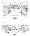
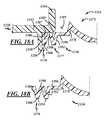
- FIG. 14Ais a fragmentary sectional view of a dispensing assembly in accordance with a ninth exemplary embodiment
- FIG. 14Bis a fragmentary sectional view of a dispensing valve of the assembly of FIG. 14A ;
- FIG. 15Ais a fragmentary sectional view of a dispensing assembly in accordance with a tenth exemplary embodiment
- FIG. 15Bis a fragmentary sectional view of a dispensing valve of the assembly of FIG. 15A ;
- FIG. 16Ais a fragmentary sectional view of a dispensing assembly in accordance with an eleventh exemplary embodiment
- FIG. 16Bis a fragmentary sectional view of a dispensing valve of the assembly of FIG. 16A ;
- FIG. 17Ais a fragmentary sectional view of a dispensing assembly in accordance with a twelfth exemplary embodiment
- FIG. 17Bis a fragmentary sectional view of a dispensing valve of the assembly of FIG. 17A ;
- FIG. 18Ais a fragmentary sectional view of a dispensing assembly in accordance with a thirteenth exemplary embodiment.
- FIG. 18Bis a fragmentary sectional view of a dispensing valve of the assembly of FIG. 18A .
- FIG. 1illustrates a dispensing package 20 in accordance with one presently preferred embodiment of the disclosure as comprising a container 22 and a dispensing assembly 24 secured to the container 22 .
- the package 20may be used to contain and dispense any suitable product, for example, fluid products such as beverages, body lotions, and food condiments, for instance, ketchup, mustard, mayonnaise, or the like.
- a liner 26may be disposed between the container 22 and the dispensing assembly 24 in any suitable manner.
- the package 20extends along a longitudinal axis A.
- the container 22may be of one-piece integrally molded plastic construction and may be composed of any suitable container material compatible with the product to be contained.
- the container 22has a flexible resilient body 28 for holding product to be dispensed, and for being squeezed from its state of rest to dispense product and being released from its squeezed state to automatically return to its state of rest to withdraw residual product back into the container 22 .
- a cylindrical neck finish 30extends from the body 28 and surrounds and establishes a container mouth.
- the neck finish 30may include one or more engagement elements, for example, external beads or threads 32 for securing the dispensing assembly 24 to the container 22 .
- threadsincludes one or more threads or thread segments that may be continuous or discontinuous and may or may not extend around the entire circumference of the neck finish 30 .
- the dispensing assembly 24may be a two-piece assembly that includes a dispensing structure, for example a shell 34 , to which a dispensing valve 36 is secured.
- a dispensing structurefor example a shell 34
- the dispensing structuremay instead include a portion of a container.
- the shell 34may be of one-piece integrally molded plastic construction, and may be composed of any suitable material compatible with the product to be contained and dispensed.
- the shell 34may be composed of polypropylene, polyethylene, polypropylene copolymer, polyethylene copolymer, or any other suitable thermoplastic or thermoplastic-copolymer.
- the valve 36may be of one-piece integrally molded plastic construction, and may be composed of any suitable elastomeric material compatible with the product to be contained and dispensed.
- the valve 36may be composed of an elastomeric material that is recyclable with the material of the shell 34 .
- the valve 36may be composed of an elastomeric material that is melt compatible or melt processible with the shell 34 .
- the material density of the valve 36is less than 1.0 gm/cc. In another preferred embodiment, the material density of the valve 36 is less than 0.98 gm/cc. In a further preferred embodiment, the material density of the valve 36 is less than 0.92 gm/cc.
- the packagein a post-consumer recycling stream of a package including the dispensing assembly 24 assembled on a polyethylene terephthalate (PET) container, the package is ground up and grindings are disposed in water in a float/sink separating tank. The PET container grindings sink because the PET density is greater than 1.0 gm/cc, whereas the shell and valve grindings float because their material densities are less than 1.0 gm/cc.
- PETpolyethylene terephthalate
- the shell and valve grindingscan be skimmed off and separated from the container material.
- Such an outcomeis in contrast to that experienced with current dispensing closures known in the art and marketplace, wherein silicone rubber vulcanizates or elastomer materials used to construct the valve typically have densities greater than 1.0 gm/cc and, thus, may become commingled with the PET container material during the post-consumer recycling operation and contaminate the PET material during further recycling operations.
- valve 36is preferably composed of a thermoplastic or a thermoplastic elastomer
- the valve 36may be composed of any suitable polymeric material.
- the valve 36may be composed of a thermoset polymer, for example, silicone rubber vulcanizates.
- the valve 36may have a density higher than 1.0 gm/cc.
- the shell 34includes a base 38 to which a lid 40 may be pivotally secured by a hinge (not shown).
- the hingemay be a snap hinge of the type illustrated in U.S. Pat. Nos. 5,794,308 and 6,041,477. However, the disclosure is by no means limited to hinges of this type, and other hinge arrangements can be employed.
- the base 38includes a deck 42 and an opening wall 44 of the deck 42 may be of any suitable shape.
- the opening wall 44may extend substantially perpendicularly to the axis A as shown, or may be domed, for instance, of conical construction.
- terms like substantially and generallymay include manufacturing tolerances, variations for good molding practices, and/or the like.
- a dispensing passage or opening 46is positioned in the deck opening wall 44 , and is preferably centrally positioned.
- a valve mounting structure, for instance and annular wall 48extends axially from an undersurface of the deck opening wall 44 surrounding and coaxial with the dispensing opening 46 .
- the valve 36may be carried within the annular wall 48 and in communication with the dispensing passage or opening 46 .
- a radially inwardly extending internal bead 50may be provided on the annular wall 48 , and may be either circumferentially continuous or segmented.
- the base 38includes an internal skirt 52 with internal attachment means, such as threads or thread segments 54 , for securing the closure shell 34 to the container neck finish 30 , and an external skirt 56 that axially extends from a radial periphery of the base 38 .
- the external skirt 56may be of a geometry to match the geometry of the associated container 22 , such as cylindrical in the embodiment illustrated in the drawings.
- a circumferential array of radially and axially extending ribs 58may interconnect the skirts 52 , 56 for strengthening and rigidifying the closure shell base 38 .
- Single wall closure shellsalso can be employed.
- a radially peripheral portion of the deck 42also includes a ledge 60 that is axially recessed with respect to opening wall 44 .
- the ledge 60extends entirely around the opening wall 44 in a plane that preferably is perpendicular to the axis A.
- a radially outwardly extending circumferential bead 62may extend at least part way around the deck 42 axially adjacent to but spaced from the ledge 60 .
- the lid 40includes a base wall 64 and a radially peripheral skirt 66 .
- An edge 68 of the skirt 66 remote from the base wall 64preferably lies in a plane, and is adapted for edge engagement with the ledge 60 on the base 38 in the closed position of the lid 40 .
- An internal bead 70preferably extends at least part way around the lid skirt 66 for snap-receipt over the bead 62 to hold the lid 40 in the closed position.
- An annular bead 72 on the lid base wall 64contacts an upper surface of the deck 42 of the base 38 in the closed position of the lid 40 .
- a plug 74may be disposed radially within the bead 72 and may be disposed adjacent to the valve 36 in the closed position of the lid 40 .
- the plug 74may be a solid cylinder, crossed walls, or the like. The plug 74 may contact the valve 36 to help prevent the valve 36 from opening when the lid 40 is closed, thereby preventing undesired leakage of product from within the package 20 .
- the lid 40need not include the plug 74 .
- the valve 36includes a resiliently flexible opening portion 75 through which product may flow, a resiliently flexible attachment or mounting portion 76 by which the valve 36 may be at least partially mounted to the closure shell base 38 , and a resiliently flexible isolating portion 77 coupled between the opening and mounting portions 75 , 76 .
- the isolating portion 77at least partially isolates the opening portion 75 from the mounting portion 76 to ensure good working operation of the opening portion 75 .
- the isolating portion 77may reduce the influence of side pressure on the opening and sealing performance of the opening portion 75 .
- the opening portion 75is configured to open and close to allow and block flow of product therethrough.
- the opening portion 75includes a radially inward annular wall 78 , and a web 80 that extends radially inwardly of the annular wall 78 .
- directional wordssuch as “axial,” “radial” and “lateral” are taken with respect to a longitudinal axis of a package, which is preferably coaxial with the axis of the container neck finish.
- directional wordssuch as “inward” and “outward” are taken with respect to the package interior.
- the web 80may be a circular or disc-like element that extends transversely across the axis A and includes one or more openings through which fluid product may flow.
- the web 80may include two or more valve petals 82 that may be established by two or more slits 84 . Because FIG. 2 is a sectional view, only one slit 84 and two petals 82 can be seen, but any suitable quantity of the petals 82 and slits 84 may be provided. In one example, a single straight slit may be provided to establish two straight petals 82 . In another example, an omega-shaped slit may be provided to establish a flap. In other examples, the web 80 may include one or more other types of openings instead of or in addition to the slit(s) 84 , for instance, one or more self-sealing apertures, flaps, or the like.
- the web 80may be dish-shaped or concave-shaped to extend both axially and radially inwardly from an axially outward end of the wall 78 .
- the web 80may be of any suitable shape and configuration.
- transverseincludes being disposed at any angle with respect to an axis including, but not limited to, a perpendicular orientation.
- the wall 78extends radially inwardly from the web 80 and may also extend radially outwardly from the web 80 so as to have a conical shape.
- the mounting portion 76is configured to couple the valve 36 to the annular wall 48 of the closure shell base 38 .
- the mounting portion 76may be annular in shape and disposed at a radially outward periphery of the valve 36 .
- the mounting portion 76includes an annular leg or wall 86 that extends from an axially inward surface 88 of the valve 36 to an axially outward surface 90 of the valve 36 in a radially inward direction so as to have a conical shape. Accordingly, a radial space 67 may be established between the axially outward end of the mounting portion 76 and the annular wall 48 of the closure shell base 38 .
- the axially outward surface 90may be in sealing contact with a corresponding axially inward surface of the closure shell base 38 .
- the isolating portion 77is configured to flexibly couple the opening portion 75 to the mounting portion 76 so as to at least partially isolate the opening portion 75 of the valve from the mounting portion 76 . Accordingly, any distortion or misalignment of, or pressure on, the mounting portion 76 will have little to no influence on the ability of the petals 82 of the opening portion 75 to properly or correctly seat to one another to seal the valve 36 closed.
- the isolating portion 77may include an annular leg or wall 92 that is radially inward with respect to the radially outward annular wall 86 , and radially intermediate with respect to the annular wall and the radially inward annular wall 78 .
- the radially intermediate annular wall 92may include an axially inward end coupled to the radially inward annular wall 78 .
- the axially inward end of the wall 92may be coupled directly to an axially inward end of the wall 78 .
- the radially intermediate annular wall 92may be cantilevered from the radially inward annular wall 78 .
- the intermediate annular wall 92may extend axially outwardly and terminate in an axially outward end that may be coupled to the mounting portion 76 . More specifically, the axially outward end of the intermediate annular wall 92 may be coupled directly to an axially outward end of the mounting portion 76 .
- the intermediate annular wall 92also may extend radially outwardly, wherein the intermediate annular wall 92 and the mounting portion 76 form an inverted V-shaped annular portion that is disposed radially outwardly of the opening portion 75 . Accordingly, a wedge-shaped radial space 89 may be established between the mounting portion 76 and the intermediate annular wall 92 .
- the inward and intermediate annular walls 78 , 92also may form a V-shaped structure. Accordingly, a wedge-shaped radial space 85 may be established between the annular walls 78 , 92 .
- the radially outward annular wall 86may be cantilevered from the radially intermediate annular wall 92 .
- the valve 36additionally may include one or more vacuum breaks 94 in or on an axially inward most surface of the valve 36 .
- the axially inward most surface of the valve 36is the axially inward surface 88 of the mounting portion 76 .
- the vacuum break(s) 94may include one or more slots, channels, or other reliefs molded, cut, or otherwise provided in the valve 36 .
- the vacuum break(s) 94may also or instead include one or more ribs, ridges, bumps, or other projections molded or otherwise provided on the valve 36 .
- the vacuum break(s)may be circumferentially spaced and radially extending. The vacuum break(s) 94 may reduce occurrences of two valves 36 from sticking to one another and/or to material handling equipment during production of the dispensing assembly 24 .
- the dispensing assembly 24may be produced in any suitable manner.
- the shell 34may be manufactured by injection or compression molding, or in any other suitable fashion.
- the valve 36may be injection or compression molded and then cut or formed in a downstream operation to establish the slit(s) 84 , or may be manufactured in any other suitable manner.
- the isolating portion 77may assist in maintaining good recombination or seating between the valve petals 82 during and after slitting of the web 80 to establish the slit(s) 84 .
- valve 36may be assembled to the closure shell 34 in any suitable manner.
- the closure shell 34may be held by a die, holder, or other tool (not shown) in any suitable fashion, and the valve 36 may be inserted within the annular wall 48 by another tool (not shown) from an axially inward side of the closure shell base 38 and retained thereto by the bead 50 , by friction, by crimping, and/or any other suitable means.
- the valve 36may be held by a die, holder, or other tool (not shown) in any suitable fashion, and the closure shell 34 may be placed over the valve 36 so that the annular wall 48 envelops the valve 36 and is retained thereto by the bead 50 and/or by friction.
- the tool that supports the valve 36may be configured to contact a suitable portion of the axially inward surface of the valve 36 to allow the valve 36 to be assembled relative to the closure shell 34 to maintain the petals 82 in good sealing contact and/or to prevent the petals 82 from becoming distorted and unseated or unsealed with respect to one another.
- the toolmay support the axial inward surface of the valve 36 in a radial direction from about the axial inward ends of the annular walls 78 , 92 , and in at least a portion of the radial space 89 .
- the toolmay further support the valve 36 by extending entirely radially across the radial space 89 and up to the axially inward surface 88 of the outward peripheral portion 86 .
- the tooladditionally may support the valve 36 by further extending radially outward over at least a portion of the axially inward surface 88 of the outward peripheral portion 86 . Therefore, the valve 36 may be supported by the tool on surfaces of the axially inward side of the valve 36 that are radially outboard of the opening portion 275 .
- valve design of the present disclosurereduces or prevents valve distortion like valve petal puckering or unseating by absorbing forces that would otherwise cause such distortion. More specifically, the flexible coupling provided by the isolating portion 77 between the opening portion 75 and the mounting portion 76 is provided to absorb such forces so that the petals 82 will properly seat to one another to seal the valve 36 closed.
- the liner 26may be initially secured to the closure shell base 38 and made part of the assembly 24 .
- the assembly 24may be delivered for use in a fluid product packaging environment.
- the container 22is filled with product to be dispensed with the dispensing assembly 24 removed.
- the dispensing assembly 24is then secured to the container neck finish 30 .
- the liner 26may have been placed within the closure skirt 52 and carried by the closure shell base 38 prior to securement of the dispensing assembly 24 to the container neck finish 30 .
- the liner 26may be an induction seal liner, which may comprise a layered construction, having an underlayer of plastic and a layer of metal foil, for example.
- the metal foilmay be heated by induction to melt at least peripheral portions of the plastic layer to secure the liner 26 to the end of the container neck finish 30 so as to seal the product-containing container 22 .
- the dispensing assembly 24is removed by the user and the liner 26 —having been previously induction sealed to the container neck finish 30 —is cut or peeled away from the container neck finish 30 .
- the dispensing assembly 24is then resecured to the container neck finish 30 .
- the closure lid 40pivoted to an open position (not shown)
- the package 20may be shaken to prepare the product for dispensing. Shaking of the package 20 does not result in spillage or ejection of product because of the valve 36 .
- the usermay squeeze and thereby pressurize the container body 28 to move product through the valve 36 .
- the valve 36may resiliently flex to allow product to move therethrough.
- the wall 78may resiliently flex radially outwardly into the radial space 85 .
- at least a portion of the intermediate annular wall 92may resiliently flex.
- the container body 28may be released.
- the vacuum produced by the container body 28 returning to its original shapemay cause some product to be withdrawn or pulled back through the valve 36 for a clean shut-off of product and a clean dispensing opening 46 .
- one or more portions of the valve 36may return to a rest position.
- one or more of the walls 78 and/or 92may resiliently return to rest positions.
- valve design of the present disclosurereduces or prevents valve distortion like valve petal puckering or unseating by absorbing residual radial pressure that would otherwise cause such distortion. More specifically, such pressure can be absorbed by the flexible coupling provided by the isolating portion 77 between the opening portion 75 and the mounting portion 76 . Therefore, the petals 82 will properly seal to one another to close the valve 36 .
- the lid 40may be closed and snapped over the closure shell base 38 . Accordingly, with embodiments that include the plug 74 , the plug 74 may contact the opening portion 75 of the valve 36 to prevent dispensing of product.
- FIGS. 3 through 18Billustrate several other exemplary embodiments of the present disclosure. These embodiments are similar in many respects to one another and to the embodiment of FIGS. 1 and 2 , and like numerals between the embodiments designate like or corresponding elements throughout the several views of the drawing figures. Additionally, the descriptions of the embodiments are incorporated by reference into one another and the common subject matter generally may not be repeated.
- FIG. 3illustrates a dispensing assembly 124 in accordance with another presently preferred embodiment of the disclosure.
- the assembly 124extends along a longitudinal axis A, and may be a two-piece assembly that includes a shell 134 to which a dispensing valve 136 is secured.
- the shell 134includes a base 138 to which a lid 140 may be pivotally secured by a hinge (not shown).
- the base 138includes a deck 142 and an opening wall 144 of the deck 142 .
- the deck 142may be of domed, cylindrical, or conical construction. In particular, the deck 142 may be incurvately conical.
- the opening wall 144 of the deck 142may extend axially and radially inwardly toward a dispensing opening 146 .
- the opening wall 144may be of conical construction.
- An annular wall 148extends axially from an undersurface of the deck opening wall 144 surrounding and coaxial with the dispensing opening 146 .
- a radially inwardly extending internal bead 150may be provided on the annular wall 148 .
- the lid 140includes a base wall 164 , an annular bead 172 extending from the base wall 164 and disposed between the opening wall 144 and the valve 136 , and a plug 174 disposed radially within the bead 172 and disposed adjacent to the valve 136 in a closed position of the lid 140 .
- the valve 136generally includes a resiliently flexible opening portion 175 that may have one or more slits 184 ( FIG. 4 ) through which product may flow, a resiliently flexible mounting portion 176 by which the valve 136 may be at least partially mounted to the closure shell base 138 , and a resiliently flexible isolating portion 177 by which the opening portion 175 is at least partially isolated from the mounting portion 176 to ensure good working operation of the opening portion 175 .
- the opening portion 175includes a radially inward annular wall 178 , and a web 180 that may include a plurality of petals 182 ( FIG. 4 ) established by crossed slits 184 ( FIG. 4 ).
- the isolating portion 177includes a radially intermediate annular wall 192 that extends at an angle of about 0-60 degrees from the axis A, and a space 185 ( FIG. 6 ) is established between the walls 178 , 192 .
- the mounting portion 176includes a radially outward annular wall 186 that extends at a suitable angle from the axis A (for example any angle in a range extending plus or minus sixty degrees from the axis A), and a space 189 ( FIG. 6 ) is established between the walls 186 , 192 .
- the valve 136is similar to the valve 36 of FIGS. 1-2 , with a couple of exceptions.
- the wall 186 of the mounting portion 176includes an axially inward surface 188 , a cylindrical surface 183 adjacent the surface 188 , and a step 181 between the surfaces 183 , 188 for positive retention of the valve 136 to the annular wall 148 of the closure shell base 138 ( FIG. 3 ).
- the wall 186may be radiused radially inward and outward of the axially inward surface 188 , and the wall 186 may have a conical outer profile that extends axially outwardly from the cylindrical surface 183 .
- the isolating portion 177also includes a plurality of ribs 199 extending between the mounting and isolating portions 176 , 177 . More specifically, the ribs 199 may extend between the radially outer and intermediate walls 186 , 192 . Thus, the ribs 199 extend at least partially into the space 189 ( FIG. 6 ) between the mounting and isolation portions 176 , 177 . The ribs 199 may provide additional resiliency to the valve 136 .
- a dispensing assembly 224includes a valve 236 including an opening portion 275 , a mounting portion 276 , and an isolating portion 277 .
- a closure shell base 238includes a deck opening wall 244 that corresponds to a radially intermediate annular wall 292 of the valve 236 .
- the deck opening wall 244may extend axially and radially inwardly toward a dispensing opening 246 to form a conical shape in correspondence with the intermediate annular wall 292 of the valve 236 .
- a radial space 285may be established between the intermediate annular wall 292 and/or the deck opening wall 244 on the one hand, and a radially inward annular wall 278 of the valve opening portion 275 on the other.
- the valve 236may include one or more vacuum breaks 294 in an axially inward most surface 288 of the valve 236 , wherein the axially inward most surface 288 is provided in one or both of axially inward ends of the wall(s) 278 , 292 .
- a dispensing assembly 324includes a valve 336 including an opening portion 375 , a mounting portion 376 , and an isolating portion 377 .
- a closure shell base 338includes a valve retaining projection 345 that may extend axially inwardly and radially outwardly to further retain the valve 336 to the shell base 338 .
- the mounting portion 376includes a radially outward wall 386 that may be L-shaped and extends from an outer end of a radially intermediate annular wall 392 to an axially outward surface 390 of the valve 336 . Accordingly, an open radial space 389 may be established between the mounting portion 376 and the intermediate annular wall 392 .
- a dispensing assembly 424includes a valve 436 including an opening portion 475 , a mounting portion 476 , and an isolating portion 477 .
- a closure shell base 438includes an axially outward extending annular bead 443 between a portion of a deck 442 and an axially inwardly conical opening wall 444 of the deck 442 .
- a mounting portion 476is disposed at such an angle so as to form, between the mounting portion 476 and a radially intermediate annular wall 492 , a radial space 489 in a general shape of a triangle.
- a dispensing assembly 524includes a valve 536 including an opening portion 575 , a mounting portion 576 , and an isolating portion 577 .
- a closure shell base 538includes an axially inwardly extending annular wall 548 having an annular bead 550 with a flat retention surface 551 for positive retention of the mounting portion 576 .
- a dispensing assembly 624includes a valve 636 including an opening portion 675 , a mounting portion 676 , and an isolating portion 677 .
- This embodimentis similar to the embodiment of FIG. 8 , with a couple of exceptions.
- a closure shell base 638does not include the valve retaining projection 345 of FIG. 8
- a mounting portion 676 of a valve 636is substantially rectangular in shape.
- a radially outward wall 686is greater in radial width than in axial height.
- a dispensing assembly 724includes a valve 736 including an opening portion 775 , a mounting portion 776 , and an isolating portion 777 .
- This embodimentis similar to the dispensing assembly 624 of FIG. 11 , with a couple of exceptions.
- An annular wall 748 of a closure shell base 738is crimped over a mounting portion 776 of the valve 736 to form a crimped portion 750 instead of a molded bead for positive retention of the valve 736 .
- the mounting portion 776includes annular attachment rings 749 interdigitated with corresponding annular attachment rings 745 of the closure shell base 738 for additional positive retention of the valve 736 .
- a dispensing assembly 724is disclosed as shown in FIG. 12 .
- the dispensing assembly 724is adapted to mount on a neck finish of a container to control discharge of a product stored in a body of the container to surroundings outside of the container through a container mouth established by the neck finish along a longitudinal axis A of the container as suggested in FIGS. 1 and 12 .
- the dispensing assembly 724may include a base 738 and a dispensing valve 736 as shown in FIG. 12 .
- the base 738may be adapted to mount to a neck finish of a container as suggested in FIGS. 1 and 12 .
- the base 738may include a deck (similar to deck 42 in FIG. 2 ), an opening wall (similar to opening wall 244 in FIG. 7 ), and an annular wall 748 as shown in FIG. 12 .
- the opening wallmay extend inward in an axial direction from the deck toward the body of the container around a dispensing opening arranged to receive product discharged from the container through the neck finish (similar to dispensing opening 246 in FIG. 7 ) as shown in FIG. 12 .
- the annular wall 748may extend inward in the axial direction along the longitudinal axis from an undersurface of the deck toward the body of the container as shown in FIG. 12 .
- the dispensing valve 736may be coupled to the base 738 to lie in the dispensing opening as shown in FIG. 12 .
- the dispensing valve 736may include an opening portion 775 , a mounting portion 776 , and an isolating portion 777 as shown in FIG. 12 .
- the opening portion 775may be adapted to allow product to be dispensed through the dispensing valve 736 as suggested in FIG. 12 .
- the mounting portion 776may be adapted to mate with the base 738 as shown in FIG. 12 .
- the isolating portion 777may extend outward from the longitudinal axis in a radial direction from the opening portion 775 to the mounting portion 776 to couple the opening portion 775 to the mounting portion 776 for movement relative thereto so that radial forces on the mounting portion 776 induced by a user squeezing the container causing distortion of the mounting portion 776 are absorbed by the isolating portion 777 rather than being transmitted to the opening portion 755 thereby reducing distortion of the opening portion 775 when a user squeezes the container to dispense product in the container as suggested in FIG. 12 .
- the annular wall 748 of the base 738may include a main portion surrounding an outer diameter of the mounting portion 776 of the dispensing valve 736 and a crimped portion 750 extending inward in the radial direction from the main portion of the annular wall 748 toward the longitudinal axis of the container as shown in FIG. 12 .
- a portion of the deckmay be arranged to extend above and mate with a topside of the mounting portion 776 of the dispensing valve 736 as shown in FIG. 12 .
- the crimped portion 750 of the annular wall 748may be arranged to extend under and mate with an underside of the mounting portion 776 of the dispensing valve 736 as shown in FIG. 12 .
- the mounting portion 776 of the dispensing valve 736may be blocked from movement outward and inward in the axial direction relative to the deck when the dispensing valve 736 is coupled to the base 738 as shown in FIG. 12 .
- the crimped portion 750may have an annular shape and may be arranged to surround the longitudinal axis of the container as suggested in FIG. 12 .
- the deckmay include an annular inner segment arranged to interconnect the annular wall 748 and the opening wall and an annular outer segment arranged to surround the annular inner segment as shown in FIG. 12 .
- the annular inner segment of the deck, the main portion of the annular wall 748 , and the crimped portion 750may cooperate to form an annular channel opening toward the longitudinal axis as shown in FIG. 12 .
- the annular channelmay receive peripheral portions of the mounting portion 776 of the dispensing valve 736 therein as shown in FIG. 12 .
- the mounting portion 776 of the dispensing valve 736may include an annular disc portion and a plurality of annular rings 749 arranged to extend outward in the axial direction from the annular disc portion away from the body of the container as shown in FIG. 12 .
- the base 738may include a plurality of annular rings 745 arranged to extend inward in the axial direction from the annular inner segment toward the body of the container as shown in FIG. 12 .
- the plurality of annular rings 749 included in the mounting portion 776may interdigitate with the plurality of annular rings 745 included in the base 738 to retain the mounting portion 776 of the dispensing valve 736 in place relative to the base 738 as shown in FIG. 12 .
- the main portion of the annular wall 748 included in the base 738may mate with an outer diameter of the mounting portion 776 of the dispensing valve 736 as shown in FIG. 12 .
- the main portion of the annular wall 748may block movement of the dispensing valve 736 in the radial direction as shown in FIG. 12 .
- the topside of the mounting portion 776may be spaced above the opening portion 775 along the longitudinal axis of the container as shown in FIG. 12 .
- the mounting portion 776may be spaced further from the body of the container than the opening portion 775 as suggested in FIG. 12 .
- the opening portion 775includes a web (similar to the web 80 in FIG. 2 ) formed to include a first slit (similar to the slit 84 in FIG. 2 ) and an annular wall (similar to annular wall 78 in FIG. 2 ) as shown in FIG. 12 .
- the annular wall of the opening portion 775may extends outward from the longitudinal axis in the radial direction from the web and inward in the axial direction from the web toward the body of the container as suggested in FIG. 12 .
- the isolating portion 777may include an intermediate annular wall (similar to intermediate annular wall 292 of FIG. 7 ) as shown in FIG. 12 .
- the intermediate annular wall of isolating portion 777may extend outward in the radial direction from the annular wall of the opening portion 775 and may extend outward in the axial direction from the annular wall of the opening portion 775 away from the body of the container as suggested in FIG. 12 .
- the annular wall of the opening portion 775 and the intermediate annular wall of the isolating portion 777may cooperate to establish a wedge-shaped space (similar to the space 85 in FIG. 2 ) as shown in FIG. 12 .
- the dispensing assembly 724may include the base 738 and the dispenser 736 as shown in FIG. 12 .
- the base 738may be adapted to mount to the neck finish of the container as suggested in FIGS. 1 and 12 .
- the base 738may include a deck, an opening wall, and an annular wall 748 as shown in FIG. 12 .
- the opening wallmay extend around a dispensing opening arranged to receive product discharged from the container through the neck finish as suggested in FIGS. 1 and 12 .
- the annular wall 748may extend inward in the axial direction along the longitudinal axis from an undersurface of the deck toward the body of the container as shown in FIG. 12 .
- the dispensing valve 736may be coupled to the base 738 to lie in the dispensing opening as shown in FIG. 12 .
- the dispensing valve 736may include an opening portion 775 , a mounting portion 776 , and an isolating portion 777 as shown in FIG. 12 .
- the opening portion 775may be adapted to allow product to be dispensed through the dispensing valve 736 as shown in FIG. 12 .
- the mounting portion 776may be adapted to mate with the base 738 as shown in FIG. 12 .
- the isolating portion 777may extend outward from the longitudinal axis in a radial direction from the opening portion 775 to the mounting portion 776 as shown in FIG. 12 .
- the annular wall 748 of the base 738may include crimped means for trapping the mounting portion 776 of the dispensing valve 736 in a stationary position relative to the deck of the base 738 as suggested in FIG. 12 .
- the annular wall 748may include a main portion arranged to mate with an outer diameter of the mounting portion 776 and a crimped portion 750 arranged to extend inward in the radial direction from the main portion to form the crimped means as shown in FIG. 12 .
- a portion of the deckis arranged to extend above and mate with a topside of the mounting portion 776 of the dispensing valve 736 as shown in FIG. 12 .
- the deckmay block movement of the dispensing valve 736 outward in the axial direction relative to the deck away from the container as suggested in FIG. 12 .
- the crimped portion 750 of the annular wall 748may be arranged to extend under and mate with an underside of the mounting portion 776 of the dispensing valve 736 as shown in FIG. 12 .
- the crimped portion 750may block movement of the dispensing valve 736 inward in the axial direction relative to the deck away from the container as suggested in FIG. 12 .
- a topside of the mounting portion 776may be spaced above the opening portion 775 along the longitudinal axis of the container as shown in FIG. 12 .
- the topside of the mounting portion 776may be further from the body of the container than the opening portion 775 as suggested in FIG. 12 .
- an underside of the mounting portion 776may be spaced above the opening portion 775 along the longitudinal axis of the container as shown in FIG. 12 .
- the underside of the mounting portion 776is further from the body of the container than the opening portion 775 as shown in FIG. 12 .
- the opening portion 775may include a web formed to include a first slit and an annular wall as shown in FIG. 12 .
- the annular wallmay extend outward from the longitudinal axis in the radial direction from the web and inward in the axial direction from the web toward the body of the container as suggested in FIG. 12 .
- the isolating portion 777includes an intermediate annular wall as shown in FIG. 12 .
- the intermediate annular wallmay extend outward in the radial direction from the annular wall of the opening portion 775 and may extend outward in the axial direction from the annular wall of the opening portion 775 away from the body of the container as suggested in FIG. 12 .
- the annular wall of the opening portion 775 and the intermediate annular wall of the isolating portion 776may cooperate to establish a space therebetween as shown in FIG. 12 .
- the crimped portion 750may have an annular shape as suggested in FIG. 12 .
- the crimped portion 750may be arranged to surround the longitudinal axis of the container as shown in FIG. 12 .
- the deckmay include an annular inner segment arranged to interconnect the annular wall and the opening wall and an annular outer segment arranged to surround the annular inner segment as shown in FIG. 12 .
- the annular inner segment of the deck, the main portion of the annular wall, and the crimped portionmay cooperate to form an annular channel opening toward the longitudinal axis as shown in FIG. 12 .
- the annular channelmay receive peripheral portions of the mounting portion 776 of the dispensing valve 736 therein as shown in FIG. 12 .
- a dispensing assembly 824includes a closure shell base 838 and a valve 836 coupled thereto.
- the base 838includes a deck 842 of domed, cylindrical, or conical construction.
- the domed deck 842may be incurvately conical.
- an opening wall 844 of the deck 842may extend axially and radially inwardly toward a dispensing opening 846 .
- An annular wall 848extends axially from an undersurface of the deck 842 .
- a radially inwardly extending internal bead 850may be provided on the annular wall 848 .
- the valve 836includes an opening portion 875 , a mounting portion 876 , and an isolating portion 877 .
- the mounting portion 876does not establish an axially outward surface of the valve 836 . Rather, an axially outward surface of the valve opening portion 875 establishes the axially outward surface of the valve 836 .
- the mounting portion 876 and the isolating portion 877form an inverted U-shaped annular portion that is disposed radially outwardly of the opening portion 875 .
- the mounting portion 876includes a radially outward annular wall 886 that extends from an axially inward surface 888 of the valve 836 .
- a radially inward annular wall 878 of the opening portion 875 of the valve 836is flexibly coupled to the mounting portion 876 .
- the isolating portion 877may include a radially intermediate annular wall 892 that may include an axially inward end coupled to the inward annular wall 878 .
- the axially inward end of the wall 892may be coupled indirectly to an axially inward end of the inward annular wall 878 by way of a radially inward connecting portion 896 , which may be flat as shown or of any other suitable shape.
- the intermediate annular wall 892extends axially outwardly and terminates in an axially outward end that may be coupled to the mounting portion 876 . More specifically, the axially outward end of the intermediate annular wall 892 may be coupled indirectly to an axially outward end of the annular wall 886 by way of a radially outward connecting portion 898 of the isolating portion 877 , which may be curved as shown or may be of any other suitable shape. Accordingly, a radial space 889 may be established between the annular wall 886 and the intermediate annular wall 892 , and a radial space 885 may be established between the intermediate annular wall 892 and the inward annular wall 878 .
- valve 836is illustrated in a free state, unassembled with respect to a closure shell.
- the valve 836additionally may include one or more vacuum breaks 894 in one or more axially inward most surfaces of the valve 836 .
- the axially inward most surfacesare in the axially inward surface 888 of the mounting portion 876 , and in axially inward surfaces of the inward annular wall 878 , intermediate annular wall 892 , and the inward connection portion 896 . From a comparison of FIGS. 13A and 13B , it can be seen that the U-shaped portion of the valve 836 becomes radially compressed between the deck opening wall 844 and the deck annular wall 848 when the valve 836 is assembled to the closure shell base 838 .
- a dispensing assembly 924is similar in many respects to the dispensing assembly 824 of FIG. 13A and, for example, may include the closure shell base 838 of FIG. 13A .
- the dispensing assembly 924also includes a valve 936 including an opening portion 975 , a mounting portion 976 , and an isolating portion 977 .
- the mounting portion 976 and the isolating portion 977form a boxy or block U-shaped annular portion that is disposed radially outwardly of the opening portion 975 .
- the mounting portion 976includes a radially outward annular wall 986 that extends from an axially inward surface 988 of the valve 936 and terminates in a free axially outward end.
- a radially inward annular wall 978 of the opening portion 975 of the valve 936is flexibly coupled to the mounting portion 976 by the isolating portion 977 .
- the inward annular wall 978is indirectly coupled to the annular wall 986 by way of a radially inward connection portion 996 extending radially outward from the wall 978 , a radially intermediate annular wall 992 of the isolating portion 977 connected to the connection portion 996 , and a radially outward connection portion 998 of the isolating portion 977 extending radially between the intermediate annular wall 992 and the radially outer annular wall 986 of the mounting portion 976 .
- the connection portions 996 , 998may be flat as shown or may be of any other suitable shape.
- Axially inward ends of the inward annular wall 978 and intermediate annular wall 992are directly coupled to opposite ends of the inward connection portion 996 .
- axially inward ends of the intermediate annular wall 992 and the annular wall 986are directly coupled to opposite ends of the outward connection portion.
- the annular wall 986 and the intermediate annular wall 992extend axially outwardly and terminate in respective free axially outward ends. Accordingly, a radial space 989 may be established between the annular wall 986 and the intermediate annular wall 992 , and a radial space 985 may be established between the intermediate annular wall 992 and the inward annular wall 978 .
- valve 936is illustrated in a free state, unassembled with respect to a closure shell.
- the valve 936additionally may include one or more vacuum breaks 994 in one or more axially inward most surfaces of the valve 936 .
- the axially inward most surfacesare in the axially inward surface 988 of the mounting portion 976 , and in axially inward surfaces of the inward annular wall 978 , intermediate annular wall 992 , and the connection portions 996 , 998 . From a comparison of FIGS. 14A and 14B , it can be seen that the block U-shaped portion of the valve 936 becomes radially compressed between the deck opening wall 844 and the deck annular wall 848 when the valve 936 is assembled to the closure shell base 838 .
- a dispensing assembly 1024is similar in many respects to the dispensing assembly 824 of FIG. 13A and, for example, may include the closure shell base 838 of FIG. 13A .
- the dispensing assembly 1024also includes a valve 1036 including an opening portion 1075 , a mounting portion 1076 , and an isolating portion 1077 .
- the mounting portion 1076 , and isolating portion 1077form an M-shaped annular portion that is disposed radially outwardly of the opening portion 1075 .
- the mounting portion 1076includes a radially outward annular wall 1086 that extends from an axially inward surface 1088 of the valve 1036 and terminates in an axially outward end.
- a radially inward annular wall 1078 of the opening portion 1075 of the valve 1036is flexibly coupled to the mounting portion 1076 by the isolating portion 1077 . More specifically, the inward annular wall 1078 is indirectly coupled to the mounting portion 1076 by way of a radially intermediate annular wall 1092 of the isolating portion 1077 , and a radially inward connection portion 1096 between the intermediate annular wall 1092 and the inward annular wall 1078 .
- the isolating portion 1077also includes a radially outward connection portion 1098 between the intermediate annular wall 1092 and the mounting portion 1076 .
- the inward connection portion 1096may be flat as shown or may be of any other suitable shape, and the outward connection potion 1098 may be V-shaped as shown.
- Axially inward ends of the inward annular wall 1078 and intermediate annular wall 1092are directly coupled to opposite ends of the inward connection portion 1096 .
- axially outward ends of the intermediate annular wall 1092 and the mounting portion 1076are directly coupled to corresponding axially outward ends of the outward connection portion 1098 .
- wedge-shaped radial spaces 1087 , 1089may be established between the mounting portion 1076 and the intermediate annular wall 1092
- a radial space 1085may be established between the intermediate annular wall 1092 and the inward annular wall 1078 .
- the valve 1036is illustrated in a free state, unassembled with respect to a closure shell.
- the valve 1036additionally may include one or more vacuum breaks 1094 in one or more axially inward most surfaces of the valve 1036 .
- the vacuum breaks 1094are in the axially inward surface 1088 of the mounting portion 1076 , in axially inward surfaces of the inward annular wall 1078 , the intermediate annular wall 1092 , and the connection portions 1096 , 1098 . From a comparison of FIGS. 15A and 15B , it can be seen that the M-shaped portion of the valve 1036 becomes radially compressed between the deck opening wall 844 and the deck annular wall 848 when the valve 1036 is assembled to the closure shell base 838 .
- a dispensing assembly 1124is similar in many respects to the dispensing assembly 824 of FIG. 13A and, for example, may include the closure shell base 838 of FIG. 13A .
- the dispensing assembly 1124also includes a valve 1136 including an opening portion 1175 , a mounting portion 1176 , and an isolating portion 1177 .
- the mounting portion 1176 , and isolating portion 1177form an X-shaped annular portion that is disposed radially outwardly of the opening portion 1175 .
- the mounting portion 1176includes a radially outward annular wall 1186 that may extend from an axially inward surface 1188 of the valve 1136 and terminates in an axially outward end.
- a radially inward annular wall 1178 of the opening portion 1175 of the valve 1136is flexibly coupled to the mounting portion 1176 by the isolating portion 1177 .
- the inward annular wall 1178is indirectly coupled to the mounting portion 1176 by way of a radially intermediate annular wall 1192 of the isolating portion 1177 , a radially inward connection portion 1196 between the intermediate annular wall 1192 and the inward annular wall 1178 , and a radially outward connection portion 1198 of the isolating portion 1177 extending between the intermediate annular wall 1192 and the mounting portion 1176 .
- the inward connection portion 1196may be flat as shown or may be of any other suitable shape. Axially inward ends of the inward annular wall 1178 and intermediate annular wall 1192 are directly coupled to opposite ends of the inward connection portion 1196 .
- the outward connection portion 1198may be transverse and located axially between axially inward and outward ends of the walls 1186 , 1192 as shown. Accordingly, axially intermediate portions of the intermediate annular wall 1192 and the mounting portion 1176 are directly coupled to corresponding transverse ends of the outward connection portion 1198 . Accordingly, wedge-shaped radial spaces 1187 , 1189 may be established between the mounting portion 1176 and the intermediate annular wall 1192 , and a radial space 1185 may be established between the intermediate annular wall 1192 and the inward annular wall 1178 .
- valve 1136is illustrated in a free state, unassembled with respect to a closure shell.
- the valve 1136additionally may include one or more vacuum breaks 1194 in one or more axially inward most surfaces of the valve 1136 .
- the vacuum breaks 1194are in the axially inward surface 1188 of the mounting portion 1176 , in axially inward surfaces of the inward annular wall 1178 , and the intermediate annular wall 1192 . From a comparison of FIGS. 16A and 16B , it can be seen that the X-shaped portion of the valve 1136 becomes radially compressed between the deck opening wall 844 and the deck annular wall 848 when the valve 1136 is assembled to the closure shell base 838 .
- a dispensing assembly 1224includes a closure shell base 1238 and a valve 1236 coupled thereto.
- the base 1238includes a deck 1242 of flat construction.
- an opening wall 1244 of the deck 1242may extend axially and radially inwardly toward a dispensing opening 1246 .
- An annular wall 1248extends axially inwardly from an undersurface of the deck 1242 .
- a radially inwardly extending internal bead 1250may be provided on the annular wall 1248 .
- the valve 1236includes an opening portion 1275 , a mounting portion 1276 , and an isolating portion 1277 .
- the mounting portion 1276 and isolating portion 1277form a V-shaped annular portion that is disposed radially outwardly of the opening portion 1275 .
- the mounting portion 1276includes a radially outward annular wall 1286 that extends from an axially inward most surface 1288 of the valve 1236 .
- a radially inward annular wall 1278 of the opening portion 1275 of the valve 1236is flexibly coupled to the mounting portion 1276 .
- the isolating portion 1277may include a radially intermediate annular wall 1292 that may include an axially outward end coupled to the inward annular wall 1278 .
- the axially outward end of the wall 1292may be coupled indirectly to an axially inward end of the inward annular wall 1278 by way of a connecting portion 1296 , which may be flat as shown or of any other suitable shape.
- the intermediate annular wall 1292extends axially inwardly and terminates in an axially inward end that may be coupled to the mounting portion 1276 . More specifically, the axially inward end of the intermediate annular wall 1292 may be coupled directly to an axially inward end of the mounting portion 1276 . Accordingly, a radial space 1289 may be established between the mounting portion 1276 and the intermediate annular wall 1292 .
- valve 1236is illustrated in a free state, unassembled with respect to a closure shell.
- the valve 1236additionally may include one or more vacuum breaks 1294 in one or more axially inward most surfaces of the valve 1236 .
- the vacuum break 1294is in the axially inward surface 1288 of the valve 1236 . From a comparison of FIGS. 17A and 17B , it can be seen that the V-shaped portion of the valve 1236 becomes radially compressed radially inwardly of the deck annular wall 1248 when the valve 1236 is assembled to the closure shell base 1238 .
- a dispensing assembly 1324is similar in many respects to the dispensing assembly 1224 of FIG. 17A and, for example, may include the closure shell base 1238 of FIG. 17A .
- the dispensing assembly 1324also includes a valve 1336 including an opening portion 1375 , a mounting portion 1376 , and an isolating portion 1377 .
- the valve 1336may combine aspects of the valve 1036 of FIG. 15A and the valve 1236 of FIG. 17A .
- the mounting portion 1376 and isolating portion 1377form a W-shaped, or inverted M-shaped, annular portion that is disposed radially outwardly of the opening portion 1375 .
- the mounting portion 1376includes a radially outward annular wall 1386 that extends from an axially inward surface 1388 of the valve 1336 and terminates in an axially outward end.
- a radially inward annular wall 1378 of the opening portion 1375 of the valve 1336is flexibly coupled to the mounting portion 1376 by the isolating portion 1377 .
- the inward annular wall 1378is indirectly coupled to the mounting portion 1376 by way of a radially intermediate annular wall 1392 of the isolating portion 1377 , a radially inward connection portion 1396 between the intermediate annular wall 1392 and the inward annular wall 1378 , and a radially outward connection portion 1398 of the isolating portion 1377 between the intermediate annular wall 1392 and the mounting portion 1376 .
- the inward connection portion 1396may be flat as shown or may be of any other suitable shape, and the outward connection portion 1398 may be of an inverted V-shape as shown.
- An axially inward end of the inward annular wall 1378 and an axially outer end of the intermediate annular wall 1392are directly coupled to opposite ends of the inward connection portion 1396 .
- Axially inward ends of the intermediate annular wall 1392 and the mounting portion 1376are directly coupled to corresponding axially inward ends of the inverted V-shaped outward connection portion 1398 .
- wedge-shaped radial spaces 1387 , 1389may be established between the mounting portion 1376 and the intermediate annular wall 1392
- a radial space 1385may be established between the intermediate annular wall 1392 and the inward annular wall 1378 .
- valve 1336is illustrated in a free state, unassembled with respect to a closure shell.
- the valve 1336additionally may include one or more vacuum breaks 1394 in one or more axially inward most surfaces of the valve 1336 .
- the vacuum breaks 1394are in the axially inward surface 1388 of the mounting portion 1376 , and in axially inward surfaces of the intermediate annular wall 1392 and of the connection portion 1398 . From a comparison of FIGS. 18A and 18B , it can be seen that the W-shaped portion of the valve 1336 becomes radially compressed when the valve 1336 is assembled to the closure shell base 1238 .
Landscapes
- Engineering & Computer Science (AREA)
- Mechanical Engineering (AREA)
- Closures For Containers (AREA)
Abstract
Description
Claims (22)
Priority Applications (1)
| Application Number | Priority Date | Filing Date | Title |
|---|---|---|---|
| US13/793,749US8794489B2 (en) | 2010-01-06 | 2013-03-11 | Dispensing valve |
Applications Claiming Priority (2)
| Application Number | Priority Date | Filing Date | Title |
|---|---|---|---|
| US12/683,030US8397957B2 (en) | 2010-01-06 | 2010-01-06 | Dispensing valve |
| US13/793,749US8794489B2 (en) | 2010-01-06 | 2013-03-11 | Dispensing valve |
Related Parent Applications (1)
| Application Number | Title | Priority Date | Filing Date |
|---|---|---|---|
| US12/683,030ContinuationUS8397957B2 (en) | 2010-01-06 | 2010-01-06 | Dispensing valve |
Publications (2)
| Publication Number | Publication Date |
|---|---|
| US20130256342A1 US20130256342A1 (en) | 2013-10-03 |
| US8794489B2true US8794489B2 (en) | 2014-08-05 |
Family
ID=43735156
Family Applications (2)
| Application Number | Title | Priority Date | Filing Date |
|---|---|---|---|
| US12/683,030Active2031-04-24US8397957B2 (en) | 2010-01-06 | 2010-01-06 | Dispensing valve |
| US13/793,749ActiveUS8794489B2 (en) | 2010-01-06 | 2013-03-11 | Dispensing valve |
Family Applications Before (1)
| Application Number | Title | Priority Date | Filing Date |
|---|---|---|---|
| US12/683,030Active2031-04-24US8397957B2 (en) | 2010-01-06 | 2010-01-06 | Dispensing valve |
Country Status (2)
| Country | Link |
|---|---|
| US (2) | US8397957B2 (en) |
| WO (1) | WO2011084766A1 (en) |
Cited By (6)
| Publication number | Priority date | Publication date | Assignee | Title |
|---|---|---|---|---|
| US20160318686A1 (en)* | 2015-04-30 | 2016-11-03 | Berry Plastics Corporation | Container closure |
| US9763854B2 (en) | 2015-05-20 | 2017-09-19 | L. Perrigo Company | Flow restrictor |
| USD801827S1 (en) | 2013-03-15 | 2017-11-07 | Tc Heartland Llc | Container |
| US20180207939A1 (en)* | 2017-01-26 | 2018-07-26 | Seiko Epson Corporation | Ink bottle and bottle set |
| US10518943B2 (en) | 2013-03-15 | 2019-12-31 | Tc Heartland Llc | Container with valve |
| US12371233B2 (en) | 2020-10-19 | 2025-07-29 | Aptargroup, Inc. | Valve |
Families Citing this family (17)
| Publication number | Priority date | Publication date | Assignee | Title |
|---|---|---|---|---|
| EP1531130A1 (en)* | 2004-08-26 | 2005-05-18 | CROWN Packaging Technology, Inc | Valve retaining device |
| ES2810152T3 (en)* | 2007-03-24 | 2021-03-08 | Afa Polytek Bv | Pre-compression system for a liquid dispensing device and method of mounting such a pre-compression system |
| BR112014022760B1 (en)* | 2012-03-16 | 2022-04-19 | Aptargroup, Inc. | Dispensing valve and method for its formation |
| NL2010248C2 (en)* | 2013-02-05 | 2014-08-07 | Plasticum Group B V | Thermoplastic valve. |
| WO2015150546A1 (en) | 2014-04-03 | 2015-10-08 | Obrist Closures Switzerland Gmbh | Valve retaining device |
| CN207291315U (en) | 2016-06-10 | 2018-05-01 | 精工爱普生株式会社 | Ink replenishing container and ink replenishing system |
| CN107487084B (en) | 2016-06-10 | 2020-08-14 | 精工爱普生株式会社 | Ink replenishment container |
| CN107487086B (en) | 2016-06-10 | 2020-08-07 | 精工爱普生株式会社 | Ink replenishment container |
| RU2742443C1 (en)* | 2017-10-23 | 2021-02-05 | Аптаргруп, Инк. | Valve |
| US10836541B2 (en) | 2017-11-27 | 2020-11-17 | Gateway Plastics, Inc. | Valve for a dispensing container |
| GB201820292D0 (en)* | 2018-12-13 | 2019-01-30 | Obrist Closures Switzerland | Flow control insert |
| NL2022396B1 (en) | 2019-01-14 | 2020-08-14 | Weener Plastics Group B V | Valve carrier ring for self-closing dispensing valve |
| JP7218062B2 (en)* | 2019-06-27 | 2023-02-06 | 株式会社吉野工業所 | double container cap |
| JP7748828B2 (en)* | 2021-08-16 | 2025-10-03 | 日本クロージャー株式会社 | Synthetic resin dispensing device with valve |
| JP7705755B2 (en)* | 2021-08-16 | 2025-07-10 | 日本クロージャー株式会社 | Synthetic resin dispensing device with valve |
| WO2025076382A1 (en)* | 2023-10-05 | 2025-04-10 | H. J. Heinz Company Brands Llc | Container, closure, and methods of manufacture |
| WO2025193325A1 (en)* | 2024-03-13 | 2025-09-18 | Aptargroup, Inc. | Dispensing valve |
Citations (41)
| Publication number | Priority date | Publication date | Assignee | Title |
|---|---|---|---|---|
| US3822720A (en) | 1971-03-04 | 1974-07-09 | Noyce R | Flow control assembly |
| US4699300A (en) | 1985-10-25 | 1987-10-13 | Blake William S | Two piece dispensing closure with positive shutoff |
| US4749108A (en) | 1986-12-19 | 1988-06-07 | The Procter & Gamble Company | Bimodal storage and dispensing package including self-sealing dispensing valve to provide automatic shut-off and leak-resistant inverted storage |
| US4991745A (en) | 1989-04-25 | 1991-02-12 | Liquid Molding Systems, Inc. | Dispensing valve with trampoline-like construction |
| US5115950A (en) | 1991-01-14 | 1992-05-26 | Seaquist Closures A Divison Of Pittway Corporation | Dispensing closure with unitary structure for retaining a pressure-actuated flexible valve |
| US5161718A (en) | 1990-04-13 | 1992-11-10 | L'oreal | Assembly for dispensing at least one liquid product or a product in the form of a cream |
| US5205441A (en) | 1990-12-21 | 1993-04-27 | Firma Raimund Andris Gmbh & Co. Kg. | Suction and/or discharge valve for a metering and spray pump for dispensing liquid, low-viscosity and pasty substances |
| US5271531A (en) | 1991-01-14 | 1993-12-21 | Seaquist Closures, A Division Of Pittway Corp. | Dispensing closure with pressure-actuated flexible valve |
| DE4403080A1 (en) | 1994-02-02 | 1995-08-03 | Henkel Kgaa | Closure for a container for flowable products |
| DE19510007A1 (en) | 1994-03-25 | 1995-10-05 | Design Udo Suffa Gmbh S | Fastener with cap, e.g. for liquid soap in showers |
| DE4440211C1 (en) | 1994-11-10 | 1996-02-22 | Dental Kosmetik Gmbh Dresden | Pressure=operated dispensing cap from vessel |
| US5531363A (en) | 1994-06-10 | 1996-07-02 | Aptargroup, Inc. | Dispensing closure cartridge valve system |
| US5743443A (en) | 1995-05-17 | 1998-04-28 | Georg Menshen Gmbh & Co. Kg | Slit valve for closing off containers |
| DE29706456U1 (en) | 1997-04-11 | 1998-08-13 | Weener Plastik GmbH & Co KG, 26826 Weener | Closure for bottles or the like. |
| JPH10264954A (en) | 1997-03-25 | 1998-10-06 | Yoshino Kogyosho Co Ltd | Slit valve for content jet container |
| GB2324297A (en) | 1995-04-04 | 1998-10-21 | Courtaulds Packaging Ltd | Closure with a variable volume chamber |
| US5839614A (en) | 1991-12-06 | 1998-11-24 | Aptar Group, Inc. | Dispensing package |
| WO1999010247A1 (en) | 1997-08-21 | 1999-03-04 | Crown Cork & Seal Technologies Corporation | Valves for packaging containers |
| US5897033A (en) | 1997-06-20 | 1999-04-27 | Yoshino Kogyosho Co., Ltd. | Container having slit valve |
| US5904275A (en) | 1994-05-19 | 1999-05-18 | Zeller Plastik Gmbh | Closure with self-closing valve |
| US5924605A (en) | 1996-03-07 | 1999-07-20 | L'oreal | Dispensing head for a product of liquid to viscous consistency, comprising an elastic closing element and a dispensing unit thus equipped |
| US5927566A (en) | 1996-07-11 | 1999-07-27 | Aptargroup, Inc. | One-piece dispensing system and method for making same |
| US6095381A (en) | 1995-09-05 | 2000-08-01 | Zeller Plastik Gmbh | Self-closing seal with a sealing membrane |
| US6095382A (en) | 1998-09-21 | 2000-08-01 | Aptargroup, Inc. | Container and closure with dispensing valve and separate releasable internal shipping seal |
| US6230940B1 (en) | 1999-11-02 | 2001-05-15 | Seaquist Closures Foreign, Inc. | One-Piece dispensing system and method for making same |
| US6298554B1 (en)* | 1998-04-02 | 2001-10-09 | Owens-Illinois Closure Inc. | Flexible vented self-sealing dispensing valve |
| US6405901B1 (en) | 2000-12-22 | 2002-06-18 | Seaquist Closures Foreign, Inc. | Valve with rolling sleeve |
| US6450375B1 (en) | 1999-05-04 | 2002-09-17 | Georg Menshen Gmbh & Co. Kg | Slotted closing valve for openings of containers |
| US6543652B1 (en) | 1999-06-04 | 2003-04-08 | Crown Cork & Seal Technologies Corporation | Closure with dispensing valve |
| US6672487B1 (en) | 2002-06-07 | 2004-01-06 | Owens-Illinois Closure Inc. | Fluid dispensing closure, package and method of manufacture |
| US20040178230A1 (en) | 1999-07-29 | 2004-09-16 | Weener Plastik Gmbh & Co. Kg | Self-closing valve |
| WO2004099024A1 (en) | 2003-05-07 | 2004-11-18 | Crown Packaging Technology Inc | Valve closure |
| US20050269373A1 (en) | 2002-03-15 | 2005-12-08 | Gaiser Ricky G | Cover for dispensing closure with pressure actuated valve |
| US20050279781A1 (en) | 2004-06-22 | 2005-12-22 | Pugne Darin M | Dispensing closure, package and method of manufacture |
| US20060201976A1 (en) | 2005-03-09 | 2006-09-14 | Owens-Illinois Closure Inc. | Integrally molded dispensing valve and method of manufacture |
| US7108361B2 (en) | 2003-05-22 | 2006-09-19 | Canon Kabushiki Kaisha | Ink tank |
| US7128245B2 (en) | 2003-06-30 | 2006-10-31 | Chong Woo Co., Ltd | Dispensing closure with automatic sealing valve of single body |
| US7299952B2 (en)* | 2004-07-08 | 2007-11-27 | Stull Technologies, Inc. | Container closure and method of assembly |
| US20080237278A1 (en) | 2007-03-27 | 2008-10-02 | Liquid Molding Systems, Inc. | Dispensing valve with hydraulic hammer resistance |
| US20080314860A1 (en) | 2007-06-22 | 2008-12-25 | Owens-Lllinois Closure Inc. | Non-removable closure/finish system |
| US20090188950A1 (en) | 2008-01-25 | 2009-07-30 | Gaus David J | Valve for decorative dispensing |
Family Cites Families (5)
| Publication number | Priority date | Publication date | Assignee | Title |
|---|---|---|---|---|
| US1738080A (en)* | 1926-07-15 | 1929-12-03 | Arthur E Smith | Closure for collapsible tubes |
| ZA951404B (en) | 1994-02-23 | 1996-02-09 | Creanova Ag | Hinge arrangement |
| DK0836576T4 (en) | 1995-07-01 | 2002-11-11 | Creanova Ag | Suspension hinge arrangement, for example in a piece of sprayed plastic closures |
| US6332730B1 (en)* | 1998-08-03 | 2001-12-25 | Veresk Biosystems Limited | Container valve |
| US7412724B2 (en)* | 2003-07-31 | 2008-08-12 | International Business Machines Corporation | Data network and method for checking nodes of a data network |
- 2010
- 2010-01-06USUS12/683,030patent/US8397957B2/enactiveActive
- 2010-12-21WOPCT/US2010/061417patent/WO2011084766A1/enactiveApplication Filing
- 2013
- 2013-03-11USUS13/793,749patent/US8794489B2/enactiveActive
Patent Citations (47)
| Publication number | Priority date | Publication date | Assignee | Title |
|---|---|---|---|---|
| US3822720A (en) | 1971-03-04 | 1974-07-09 | Noyce R | Flow control assembly |
| US4699300A (en) | 1985-10-25 | 1987-10-13 | Blake William S | Two piece dispensing closure with positive shutoff |
| US4749108A (en) | 1986-12-19 | 1988-06-07 | The Procter & Gamble Company | Bimodal storage and dispensing package including self-sealing dispensing valve to provide automatic shut-off and leak-resistant inverted storage |
| US4991745A (en) | 1989-04-25 | 1991-02-12 | Liquid Molding Systems, Inc. | Dispensing valve with trampoline-like construction |
| US5161718A (en) | 1990-04-13 | 1992-11-10 | L'oreal | Assembly for dispensing at least one liquid product or a product in the form of a cream |
| US5205441A (en) | 1990-12-21 | 1993-04-27 | Firma Raimund Andris Gmbh & Co. Kg. | Suction and/or discharge valve for a metering and spray pump for dispensing liquid, low-viscosity and pasty substances |
| US5115950A (en) | 1991-01-14 | 1992-05-26 | Seaquist Closures A Divison Of Pittway Corporation | Dispensing closure with unitary structure for retaining a pressure-actuated flexible valve |
| US5271531A (en) | 1991-01-14 | 1993-12-21 | Seaquist Closures, A Division Of Pittway Corp. | Dispensing closure with pressure-actuated flexible valve |
| US5839614A (en) | 1991-12-06 | 1998-11-24 | Aptar Group, Inc. | Dispensing package |
| DE4403080A1 (en) | 1994-02-02 | 1995-08-03 | Henkel Kgaa | Closure for a container for flowable products |
| WO1995021098A1 (en) | 1994-02-02 | 1995-08-10 | Henkel Kommanditgesellschaft Auf Aktien | Closure for a container for pourable products |
| DE19510007A1 (en) | 1994-03-25 | 1995-10-05 | Design Udo Suffa Gmbh S | Fastener with cap, e.g. for liquid soap in showers |
| US5904275A (en) | 1994-05-19 | 1999-05-18 | Zeller Plastik Gmbh | Closure with self-closing valve |
| US5531363A (en) | 1994-06-10 | 1996-07-02 | Aptargroup, Inc. | Dispensing closure cartridge valve system |
| DE4440211C1 (en) | 1994-11-10 | 1996-02-22 | Dental Kosmetik Gmbh Dresden | Pressure=operated dispensing cap from vessel |
| GB2324297A (en) | 1995-04-04 | 1998-10-21 | Courtaulds Packaging Ltd | Closure with a variable volume chamber |
| US5743443A (en) | 1995-05-17 | 1998-04-28 | Georg Menshen Gmbh & Co. Kg | Slit valve for closing off containers |
| US6095381A (en) | 1995-09-05 | 2000-08-01 | Zeller Plastik Gmbh | Self-closing seal with a sealing membrane |
| US5924605A (en) | 1996-03-07 | 1999-07-20 | L'oreal | Dispensing head for a product of liquid to viscous consistency, comprising an elastic closing element and a dispensing unit thus equipped |
| US5927566A (en) | 1996-07-11 | 1999-07-27 | Aptargroup, Inc. | One-piece dispensing system and method for making same |
| JPH10264954A (en) | 1997-03-25 | 1998-10-06 | Yoshino Kogyosho Co Ltd | Slit valve for content jet container |
| DE29706456U1 (en) | 1997-04-11 | 1998-08-13 | Weener Plastik GmbH & Co KG, 26826 Weener | Closure for bottles or the like. |
| US5897033A (en) | 1997-06-20 | 1999-04-27 | Yoshino Kogyosho Co., Ltd. | Container having slit valve |
| WO1999010247A1 (en) | 1997-08-21 | 1999-03-04 | Crown Cork & Seal Technologies Corporation | Valves for packaging containers |
| US6273305B1 (en) | 1997-08-21 | 2001-08-14 | Crown Cork & Seal Technologies Corporation | Valves for packaging containers |
| US6298554B1 (en)* | 1998-04-02 | 2001-10-09 | Owens-Illinois Closure Inc. | Flexible vented self-sealing dispensing valve |
| US6095382A (en) | 1998-09-21 | 2000-08-01 | Aptargroup, Inc. | Container and closure with dispensing valve and separate releasable internal shipping seal |
| US6450375B1 (en) | 1999-05-04 | 2002-09-17 | Georg Menshen Gmbh & Co. Kg | Slotted closing valve for openings of containers |
| US6543652B1 (en) | 1999-06-04 | 2003-04-08 | Crown Cork & Seal Technologies Corporation | Closure with dispensing valve |
| US20040178230A1 (en) | 1999-07-29 | 2004-09-16 | Weener Plastik Gmbh & Co. Kg | Self-closing valve |
| US6230940B1 (en) | 1999-11-02 | 2001-05-15 | Seaquist Closures Foreign, Inc. | One-Piece dispensing system and method for making same |
| US6405901B1 (en) | 2000-12-22 | 2002-06-18 | Seaquist Closures Foreign, Inc. | Valve with rolling sleeve |
| US20050269373A1 (en) | 2002-03-15 | 2005-12-08 | Gaiser Ricky G | Cover for dispensing closure with pressure actuated valve |
| US6672487B1 (en) | 2002-06-07 | 2004-01-06 | Owens-Illinois Closure Inc. | Fluid dispensing closure, package and method of manufacture |
| WO2004099024A1 (en) | 2003-05-07 | 2004-11-18 | Crown Packaging Technology Inc | Valve closure |
| US20060249545A1 (en) | 2003-05-07 | 2006-11-09 | Crown Packaging Technology Inc. | Valve closure |
| US7108361B2 (en) | 2003-05-22 | 2006-09-19 | Canon Kabushiki Kaisha | Ink tank |
| US7128245B2 (en) | 2003-06-30 | 2006-10-31 | Chong Woo Co., Ltd | Dispensing closure with automatic sealing valve of single body |
| US20050279781A1 (en) | 2004-06-22 | 2005-12-22 | Pugne Darin M | Dispensing closure, package and method of manufacture |
| US7255250B2 (en) | 2004-06-22 | 2007-08-14 | Owens-Illinois Closure Inc. | Dispensing closure, package and method of manufacture |
| US20070251079A1 (en) | 2004-06-22 | 2007-11-01 | Pugne Darin M | Dispensing closure, package and method of manufacture |
| US7299952B2 (en)* | 2004-07-08 | 2007-11-27 | Stull Technologies, Inc. | Container closure and method of assembly |
| US20060201976A1 (en) | 2005-03-09 | 2006-09-14 | Owens-Illinois Closure Inc. | Integrally molded dispensing valve and method of manufacture |
| US7503469B2 (en) | 2005-03-09 | 2009-03-17 | Rexam Closure Systems Inc. | Integrally molded dispensing valve and method of manufacture |
| US20080237278A1 (en) | 2007-03-27 | 2008-10-02 | Liquid Molding Systems, Inc. | Dispensing valve with hydraulic hammer resistance |
| US20080314860A1 (en) | 2007-06-22 | 2008-12-25 | Owens-Lllinois Closure Inc. | Non-removable closure/finish system |
| US20090188950A1 (en) | 2008-01-25 | 2009-07-30 | Gaus David J | Valve for decorative dispensing |
Cited By (13)
| Publication number | Priority date | Publication date | Assignee | Title |
|---|---|---|---|---|
| USD945886S1 (en) | 2013-03-15 | 2022-03-15 | Tc Heartland Llc | Container |
| USD801827S1 (en) | 2013-03-15 | 2017-11-07 | Tc Heartland Llc | Container |
| USD863064S1 (en) | 2013-03-15 | 2019-10-15 | Tc Heartland Llc | Container |
| US10518943B2 (en) | 2013-03-15 | 2019-12-31 | Tc Heartland Llc | Container with valve |
| US9994379B2 (en)* | 2015-04-30 | 2018-06-12 | Berry Plastics Corporation | Container closure |
| US20160318686A1 (en)* | 2015-04-30 | 2016-11-03 | Berry Plastics Corporation | Container closure |
| US9763854B2 (en) | 2015-05-20 | 2017-09-19 | L. Perrigo Company | Flow restrictor |
| US10849826B2 (en) | 2015-05-20 | 2020-12-01 | L. Perrigo Company | Flow restrictor |
| US20180207939A1 (en)* | 2017-01-26 | 2018-07-26 | Seiko Epson Corporation | Ink bottle and bottle set |
| US11192380B2 (en) | 2017-01-26 | 2021-12-07 | Seiko Epson Corporation | Ink bottle and bottle set |
| US11597207B2 (en) | 2017-01-26 | 2023-03-07 | Seiko Epson Corporation | Ink bottle and bottle set |
| US11932022B2 (en) | 2017-01-26 | 2024-03-19 | Seiko Epson Corporation | Ink bottle and bottle set |
| US12371233B2 (en) | 2020-10-19 | 2025-07-29 | Aptargroup, Inc. | Valve |
Also Published As
| Publication number | Publication date |
|---|---|
| US20130256342A1 (en) | 2013-10-03 |
| US20110163134A1 (en) | 2011-07-07 |
| WO2011084766A1 (en) | 2011-07-14 |
| US8397957B2 (en) | 2013-03-19 |
Similar Documents
| Publication | Publication Date | Title |
|---|---|---|
| US8794489B2 (en) | Dispensing valve | |
| US8608034B2 (en) | Dispensing valve | |
| EP1115621B1 (en) | Pressure-openable valve retained with folding elements | |
| EP2132105B1 (en) | Dispensing valve with improved dispensing | |
| US6616016B2 (en) | Closure with pressure-actuated valve and lid seal | |
| US5169035A (en) | Squeeze bottle dispensing closure with vent valve | |
| CA2387778C (en) | One-piece dispensing system and method for making same | |
| US6951295B1 (en) | Flow control element and dispensing structure incorporating same | |
| US6672487B1 (en) | Fluid dispensing closure, package and method of manufacture | |
| US20140209644A1 (en) | Dispensing valve | |
| EP2337746A1 (en) | Baffled dispensing closure | |
| CN1777548A (en) | Closures for fluid product containers | |
| US6257432B1 (en) | Cap and container assembly | |
| US20220411144A1 (en) | Self-venting closure | |
| US20250263210A1 (en) | Dispensing valve | |
| HK1078062A1 (en) | Closure with internal flow control for a pressure openable valve | |
| HK1078062B (en) | Closure with internal flow control for a pressure openable valve |
Legal Events
| Date | Code | Title | Description |
|---|---|---|---|
| AS | Assignment | Owner name:STILLWATER TRUST, FLORIDA Free format text:ASSIGNMENT OF ASSIGNORS INTEREST;ASSIGNOR:CAIRNS, JAMES;REEL/FRAME:030084/0371 Effective date:20120506 | |
| STCF | Information on status: patent grant | Free format text:PATENTED CASE | |
| AS | Assignment | Owner name:BERRY PLASTICS CORPORATION, INDIANA Free format text:ASSIGNMENT OF ASSIGNORS INTEREST;ASSIGNOR:REXAM CLOSURE SYSTEMS INC.;REEL/FRAME:033362/0080 Effective date:20111220 | |
| AS | Assignment | Owner name:BANK OF AMERICA, N.A., CALIFORNIA Free format text:SECURITY INTEREST;ASSIGNOR:BERRY PLASTICS CORPORATION;REEL/FRAME:034573/0718 Effective date:20141212 Owner name:CREDIT SUISSE AG, CAYMAN ISLANDS BRANCH, NEW YORK Free format text:SECURITY INTEREST;ASSIGNOR:BERRY PLASTICS CORPORATION;REEL/FRAME:034573/0718 Effective date:20141212 Owner name:U.S. BANK NATIONAL ASSOCIATION, NEW YORK Free format text:SECURITY INTEREST;ASSIGNOR:BERRY PLASTICS CORPORATION;REEL/FRAME:034574/0076 Effective date:20141212 | |
| MAFP | Maintenance fee payment | Free format text:PAYMENT OF MAINTENANCE FEE, 4TH YEAR, LARGE ENTITY (ORIGINAL EVENT CODE: M1551) Year of fee payment:4 | |
| AS | Assignment | Owner name:U.S. BANK NATIONAL ASSOCIATION, AS COLLATERAL AGEN Free format text:FIRST LIEN PATENT SECURITY AGREEMENT;ASSIGNORS:BERRY GLOBAL, INC.;BERRY FILM PRODUCTS COMPANY, INC.;BPREX HEALTHCARE PACKAGING INC.;AND OTHERS;REEL/FRAME:049671/0171 Effective date:20190701 Owner name:U.S. BANK NATIONAL ASSOCIATION, AS COLLATERAL AGENT, NEW YORK Free format text:FIRST LIEN PATENT SECURITY AGREEMENT;ASSIGNORS:BERRY GLOBAL, INC.;BERRY FILM PRODUCTS COMPANY, INC.;BPREX HEALTHCARE PACKAGING INC.;AND OTHERS;REEL/FRAME:049671/0171 Effective date:20190701 | |
| AS | Assignment | Owner name:U.S. BANK NATIONAL ASSOCIATION, AS COLLATERAL AGEN Free format text:FIRST LIEN PATENT SECURITY AGREEMENT;ASSIGNORS:BERRY GLOBAL, INC.;BERRY FILM PRODUCTS COMPANY, INC.;BPREX HEALTHCARE PACKAGING INC.;AND OTHERS;REEL/FRAME:051485/0318 Effective date:20200102 Owner name:U.S. BANK NATIONAL ASSOCIATION, AS COLLATERAL AGENT, NEW YORK Free format text:FIRST LIEN PATENT SECURITY AGREEMENT;ASSIGNORS:BERRY GLOBAL, INC.;BERRY FILM PRODUCTS COMPANY, INC.;BPREX HEALTHCARE PACKAGING INC.;AND OTHERS;REEL/FRAME:051485/0318 Effective date:20200102 | |
| AS | Assignment | Owner name:U.S. BANK NATIONAL ASSOCIATION, NEW YORK Free format text:FIRST LIEN PATENT SECURITY AGREEMENT;ASSIGNORS:BERRY GLOBAL, INC.;BERRY FILM PRODUCTS COMPANY, INC.;BPREX HEALTHCARE PACKAGING INC.;AND OTHERS;REEL/FRAME:054840/0047 Effective date:20201222 | |
| AS | Assignment | Owner name:U.S. BANK NATIONAL ASSOCIATION, NEW YORK Free format text:FIRST LIEN PATENT SECURITY AGREEMENT;ASSIGNORS:BERRY GLOBAL, INC.;BERRY FILM PRODUCTS COMPANY, INC.;BPREX HEALTHCARE PACKAGING INC.;AND OTHERS;REEL/FRAME:055009/0450 Effective date:20210115 | |
| AS | Assignment | Owner name:U.S. BANK NATIONAL ASSOCIATION, NEW YORK Free format text:CORRECTIVE ASSIGNMENT TO CORRECT THE LISTING OF PATENTS PREVIOUSLY RECORDED AT REEL: 054840 FRAME: 0047. ASSIGNOR(S) HEREBY CONFIRMS THE FIRST LIEN PATENT SECURITY AGREEMENT;ASSIGNORS:BERRY GLOBAL, INC.;BERRY FILM PRODUCTS COMPANY, INC.;BPREX HEALTHCARE PACKAGING INC.;AND OTHERS;REEL/FRAME:055616/0527 Effective date:20201222 Owner name:U.S. BANK NATIONAL ASSOCIATION, NEW YORK Free format text:CORRECTIVE ASSIGNMENT TO CORRECT THE LISTING OF PATENTS PREVIOUSLY RECORDED ON REEL 055009 FRAME 0450. ASSIGNOR(S) HEREBY CONFIRMS THE FIRST LIEN PATENT SECURITY AGREEMENT;ASSIGNORS:BERRY GLOBAL, INC.;BERRY FILM PRODUCTS COMPANY, INC.;BPREX HEALTHCARE PACKAGING INC.;AND OTHERS;REEL/FRAME:055742/0522 Effective date:20210115 | |
| AS | Assignment | Owner name:U.S. BANK NATIONAL ASSOCIATION, AS COLLATERAL AGENT, NEW YORK Free format text:SECURITY INTEREST;ASSIGNORS:BERRY GLOBAL, INC.;BERRY FILM PRODUCTS COMPANY, INC.;BPREX HEALTHCARE PACKAGING INC.;AND OTHERS;REEL/FRAME:056759/0001 Effective date:20210614 | |
| MAFP | Maintenance fee payment | Free format text:PAYMENT OF MAINTENANCE FEE, 8TH YEAR, LARGE ENTITY (ORIGINAL EVENT CODE: M1552); ENTITY STATUS OF PATENT OWNER: LARGE ENTITY Year of fee payment:8 | |
| AS | Assignment | Owner name:U.S. BANK NATIONAL ASSOCIATION, NEW YORK Free format text:CORRECTIVE ASSIGNMENT TO CORRECT THE THE LISTING OF PATENTS PREVIOUSLY RECORDED AT REEL: 055009 FRAME: 0450. ASSIGNOR(S) HEREBY CONFIRMS THE ASSIGNMENT;ASSIGNORS:BERRY GLOBAL, INC.;BERRY FILM PRODUCTS COMPANY, INC.;BPREX HEALTHCARE PACKAGING INC.;AND OTHERS;REEL/FRAME:058954/0677 Effective date:20210115 Owner name:U.S. BANK NATIONAL ASSOCIATION, NEW YORK Free format text:CORRECTIVE ASSIGNMENT TO CORRECT THE THE LISTING OF PATENTS PREVIOUSLY RECORDED AT REEL: 054840 FRAME: 0047. ASSIGNOR(S) HEREBY CONFIRMS THE ASSIGNMENT;ASSIGNORS:BERRY GLOBAL, INC.;BERRY FILM PRODUCTS COMPANY, INC.;BPREX HEALTHCARE PACKAGING INC.;AND OTHERS;REEL/FRAME:058954/0581 Effective date:20201222 | |
| AS | Assignment | Owner name:U.S. BANK TRUST COMPANY, NATIONAL ASSOCIATION, NEW YORK Free format text:SECURITY INTEREST;ASSIGNORS:BERRY GLOBAL, INC.;BERRY FILM PRODUCTS COMPANY, INC.;BPREX HEALTHCARE PACKAGING INC;AND OTHERS;REEL/FRAME:063348/0639 Effective date:20230330 | |
| AS | Assignment | Owner name:U.S. BANK NATIONAL ASSOCIATION, NEW YORK Free format text:CORRECTIVE ASSIGNMENT TO CORRECT THE LISTING OF PATENTS PREVIOUSLY RECORDED ON REEL 054840 FRAME 0047. ASSIGNOR(S) HEREBY CONFIRMS THE FIRST LIEN PATENT SECURITY AGREEMENT;ASSIGNORS:BERRY GLOBAL, INC.;BERRY FILM PRODUCTS COMPANY, INC.;BPREX HEALTHCARE PACKAGING INC.;AND OTHERS;REEL/FRAME:064142/0855 Effective date:20201222 Owner name:U.S. BANK NATIONAL ASSOCIATION, NEW YORK Free format text:CORRECTIVE ASSIGNMENT TO CORRECT THE APPLICATION NUMBERS PREVIOUSLY RECORDED AT REEL: 055009 FRAME: 0450. ASSIGNOR(S) HEREBY CONFIRMS THE SECURITY AGREEMENT;ASSIGNORS:BERRY GLOBAL, INC.;BERRY FILM PRODUCTS COMPANY, INC.;BPREX HEALTHCARE PACKAGING INC.;AND OTHERS;REEL/FRAME:064050/0207 Effective date:20210115 Owner name:U.S. BANK NATIONAL ASSOCIATION, NEW YORK Free format text:CORRECTIVE ASSIGNMENT TO CORRECT THE LISTING OF PATENTS PREVIOUSLY RECORDED AT REEL: 058954 FRAME: 0677. ASSIGNOR(S) HEREBY CONFIRMS THE FIRST LIEN PATENT SECURITY AGREEMENT;ASSIGNORS:BERRY GLOBAL, INC.;BERRY FILM PRODUCTS COMPANY, INC.;BPREX HEALTHCARE PACKAGING INC.;AND OTHERS;REEL/FRAME:064053/0867 Effective date:20210115 Owner name:U.S. BANK NATIONAL ASSOCIATION, NEW YORK Free format text:CORRECTIVE ASSIGNMENT TO CORRECT THE LISTING OF PATENTS PREVIOUSLY RECORDED AT REEL: 055742 FRAME: 0522. ASSIGNOR(S) HEREBY CONFIRMS THE FIRST LIEN PATENT SECURITY AGREEMENT;ASSIGNORS:BERRY GLOBAL, INC.;BERRY FILM PRODUCTS COMPANY, INC.;BPREX HEALTHCARE PACKAGING INC.;AND OTHERS;REEL/FRAME:064053/0415 Effective date:20210115 Owner name:U.S. BANK NATIONAL ASSOCIATION, AS COLLATERAL AGENT, NEW YORK Free format text:CORRECTIVE ASSIGNMENT TO CORRECT THE APPLICATION NUMBERS PREVIOUSLY RECORDED AT REEL: 056759 FRAME: 0001. ASSIGNOR(S) HEREBY CONFIRMS THE SECURITY INTEREST;ASSIGNORS:BERRY GLOBAL, INC.;BERRY FILM PRODUCTS COMPANY, INC.;BPREX HEALTHCARE PACKAGING INC.;AND OTHERS;REEL/FRAME:064050/0377 Effective date:20210614 Owner name:U.S. BANK NATIONAL ASSOCIATION, NEW YORK Free format text:CORRECTIVE ASSIGNMENT TO CORRECT THE APPLICATION NUMBERS PREVIOUSLY RECORDED AT REEL: 055616 FRAME: 0527. ASSIGNOR(S) HEREBY CONFIRMS THE SECURITY AGREEMENT;ASSIGNORS:BERRY GLOBAL, INC.;BERRY FILM PRODUCTS COMPANY, INC.;BPREX HEALTHCARE PACKAGING INC.;AND OTHERS;REEL/FRAME:064050/0620 Effective date:20201222 | |
| AS | Assignment | Owner name:U.S. BANK TRUST COMPANY, NATIONAL ASSOCIATION, NEW YORK Free format text:SECURITY INTEREST;ASSIGNORS:BERRY GLOBAL, INC.;BERRY FILM PRODUCTS COMPANY, INC.;BPREX HEALTHCARE PACKAGING INC;AND OTHERS;REEL/FRAME:066354/0346 Effective date:20240117 | |
| AS | Assignment | Owner name:U.S. BANK TRUST COMPANY, NATIONAL ASSOCIATION, NEW YORK Free format text:SECURITY INTEREST;ASSIGNORS:BERRY GLOBAL, INC.;BERRY FILM PRODUCTS COMPANY, INC.;BPREX HEALTHCARE PACKAGING INC.;AND OTHERS;REEL/FRAME:067589/0371 Effective date:20240528 | |
| AS | Assignment | Owner name:PROVIDENCIA USA, INC., INDIANA Free format text:RELEASE BY SECURED PARTY;ASSIGNOR:U.S. BANK TRUST COMPANY, NATIONAL ASSOCIATION;REEL/FRAME:069306/0067 Effective date:20241104 Owner name:FIBERWEB, LLC., INDIANA Free format text:RELEASE BY SECURED PARTY;ASSIGNOR:U.S. BANK TRUST COMPANY, NATIONAL ASSOCIATION;REEL/FRAME:069306/0067 Effective date:20241104 Owner name:AVINTIV SPECIALTY MATERIALS, LLC (F/K/A AVINTIV SPECIALTY MATERIALS INC.; F/K/A POLYMER GROUP, INC.), INDIANA Free format text:RELEASE BY SECURED PARTY;ASSIGNOR:U.S. BANK TRUST COMPANY, NATIONAL ASSOCIATION;REEL/FRAME:069306/0067 Effective date:20241104 Owner name:BERRY FILM PRODUCTS COMPANY, INC., INDIANA Free format text:RELEASE BY SECURED PARTY;ASSIGNOR:U.S. BANK TRUST COMPANY, NATIONAL ASSOCIATION;REEL/FRAME:069306/0067 Effective date:20241104 | |
| AS | Assignment | Owner name:BERRY PLASTICS CORPORATION, INDIANA Free format text:RELEASE BY SECURED PARTY;ASSIGNOR:U.S. BANK TRUST COMPANY, NATIONAL ASSOCIATION;REEL/FRAME:071003/0841 Effective date:20250430 | |
| AS | Assignment | Owner name:LETICA CORPORATION, INDIANA Free format text:PARTIAL RELEASE OF SECURITY INTEREST IN PATENTS;ASSIGNOR:U.S. BANK TRUST COMPANY, NATIONAL ASSOCIATION;REEL/FRAME:071161/0202 Effective date:20250430 Owner name:PROVIDENCIA USA, INC., INDIANA Free format text:PARTIAL RELEASE OF SECURITY INTEREST IN PATENTS;ASSIGNOR:U.S. BANK TRUST COMPANY, NATIONAL ASSOCIATION;REEL/FRAME:071161/0202 Effective date:20250430 Owner name:BERRY GLOBAL FILMS, LLC, INDIANA Free format text:PARTIAL RELEASE OF SECURITY INTEREST IN PATENTS;ASSIGNOR:U.S. BANK TRUST COMPANY, NATIONAL ASSOCIATION;REEL/FRAME:071161/0202 Effective date:20250430 Owner name:FIBERWEB, LLC, INDIANA Free format text:PARTIAL RELEASE OF SECURITY INTEREST IN PATENTS;ASSIGNOR:U.S. BANK TRUST COMPANY, NATIONAL ASSOCIATION;REEL/FRAME:071161/0202 Effective date:20250430 Owner name:PLIANT, LLC, INDIANA Free format text:PARTIAL RELEASE OF SECURITY INTEREST IN PATENTS;ASSIGNOR:U.S. BANK TRUST COMPANY, NATIONAL ASSOCIATION;REEL/FRAME:071161/0202 Effective date:20250430 Owner name:AVINTIV SPECIALTY MATERIALS INC., INDIANA Free format text:PARTIAL RELEASE OF SECURITY INTEREST IN PATENTS;ASSIGNOR:U.S. BANK TRUST COMPANY, NATIONAL ASSOCIATION;REEL/FRAME:071161/0202 Effective date:20250430 Owner name:PRIME LABEL & SCREEN, INC., INDIANA Free format text:PARTIAL RELEASE OF SECURITY INTEREST IN PATENTS;ASSIGNOR:U.S. BANK TRUST COMPANY, NATIONAL ASSOCIATION;REEL/FRAME:071161/0202 Effective date:20250430 Owner name:BPREX HEALTHCARE PACKAGING INC., INDIANA Free format text:PARTIAL RELEASE OF SECURITY INTEREST IN PATENTS;ASSIGNOR:U.S. BANK TRUST COMPANY, NATIONAL ASSOCIATION;REEL/FRAME:071161/0202 Effective date:20250430 Owner name:BERRY FILM PRODUCTS COMPANY, INC., INDIANA Free format text:PARTIAL RELEASE OF SECURITY INTEREST IN PATENTS;ASSIGNOR:U.S. BANK TRUST COMPANY, NATIONAL ASSOCIATION;REEL/FRAME:071161/0202 Effective date:20250430 Owner name:LETICA CORPORATION, INDIANA Free format text:PARTIAL RELEASE OF SECURITY INTEREST IN PATENTS;ASSIGNOR:U.S. BANK TRUST COMPANY, NATIONAL ASSOCIATION;REEL/FRAME:071161/0598 Effective date:20250430 Owner name:PROVIDENCIA USA, INC., INDIANA Free format text:PARTIAL RELEASE OF SECURITY INTEREST IN PATENTS;ASSIGNOR:U.S. BANK TRUST COMPANY, NATIONAL ASSOCIATION;REEL/FRAME:071161/0598 Effective date:20250430 Owner name:BERRY GLOBAL FILMS, LLC, ILLINOIS Free format text:PARTIAL RELEASE OF SECURITY INTEREST IN PATENTS;ASSIGNOR:U.S. BANK TRUST COMPANY, NATIONAL ASSOCIATION;REEL/FRAME:071161/0598 Effective date:20250430 Owner name:FIBERWEB, LLC, INDIANA Free format text:PARTIAL RELEASE OF SECURITY INTEREST IN PATENTS;ASSIGNOR:U.S. BANK TRUST COMPANY, NATIONAL ASSOCIATION;REEL/FRAME:071161/0598 Effective date:20250430 Owner name:PLIANT, LLC, INDIANA Free format text:PARTIAL RELEASE OF SECURITY INTEREST IN PATENTS;ASSIGNOR:U.S. BANK TRUST COMPANY, NATIONAL ASSOCIATION;REEL/FRAME:071161/0598 Effective date:20250430 Owner name:PRIME LABEL AND SCREEN INCORPORATED, INDIANA Free format text:PARTIAL RELEASE OF SECURITY INTEREST IN PATENTS;ASSIGNOR:U.S. BANK TRUST COMPANY, NATIONAL ASSOCIATION;REEL/FRAME:071161/0598 Effective date:20250430 Owner name:AVINTIV SPECIALTY MATERIALS INC., INDIANA Free format text:PARTIAL RELEASE OF SECURITY INTEREST IN PATENTS;ASSIGNOR:U.S. BANK TRUST COMPANY, NATIONAL ASSOCIATION;REEL/FRAME:071161/0598 Effective date:20250430 Owner name:PRIME LABEL & SCREEN, INC., INDIANA Free format text:PARTIAL RELEASE OF SECURITY INTEREST IN PATENTS;ASSIGNOR:U.S. BANK TRUST COMPANY, NATIONAL ASSOCIATION;REEL/FRAME:071161/0598 Effective date:20250430 Owner name:BPREX HEALTHCARE PACKAGING INC., INDIANA Free format text:PARTIAL RELEASE OF SECURITY INTEREST IN PATENTS;ASSIGNOR:U.S. BANK TRUST COMPANY, NATIONAL ASSOCIATION;REEL/FRAME:071161/0598 Effective date:20250430 Owner name:BERRY FILM PRODUCTS COMPANY, INC., INDIANA Free format text:PARTIAL RELEASE OF SECURITY INTEREST IN PATENTS;ASSIGNOR:U.S. BANK TRUST COMPANY, NATIONAL ASSOCIATION;REEL/FRAME:071161/0598 Effective date:20250430 | |
| AS | Assignment | Owner name:LETICA CORPORATION, INDIANA Free format text:RELEASE BY SECURED PARTY;ASSIGNOR:U.S. BANK TRUST COMPANY, NATIONAL ASSOCIATION;REEL/FRAME:071165/0464 Effective date:20250430 Owner name:PROVIDENCIA USA, INC., INDIANA Free format text:RELEASE BY SECURED PARTY;ASSIGNOR:U.S. BANK TRUST COMPANY, NATIONAL ASSOCIATION;REEL/FRAME:071165/0464 Effective date:20250430 Owner name:BERRY GLOBAL FILMS, LLC, INDIANA Free format text:RELEASE BY SECURED PARTY;ASSIGNOR:U.S. BANK TRUST COMPANY, NATIONAL ASSOCIATION;REEL/FRAME:071165/0464 Effective date:20250430 Owner name:FIBERWEB, LLC, INDIANA Free format text:RELEASE BY SECURED PARTY;ASSIGNOR:U.S. BANK TRUST COMPANY, NATIONAL ASSOCIATION;REEL/FRAME:071165/0464 Effective date:20250430 Owner name:PLIANT, LLC, INDIANA Free format text:RELEASE BY SECURED PARTY;ASSIGNOR:U.S. BANK TRUST COMPANY, NATIONAL ASSOCIATION;REEL/FRAME:071165/0464 Effective date:20250430 Owner name:PRIME LABEL & SCREEN INCORPORATED, INDIANA Free format text:RELEASE BY SECURED PARTY;ASSIGNOR:U.S. BANK TRUST COMPANY, NATIONAL ASSOCIATION;REEL/FRAME:071165/0464 Effective date:20250430 Owner name:AVINTIV SPECIALTY MATERIALS INC., INDIANA Free format text:RELEASE BY SECURED PARTY;ASSIGNOR:U.S. BANK TRUST COMPANY, NATIONAL ASSOCIATION;REEL/FRAME:071165/0464 Effective date:20250430 Owner name:PRIME LABEL & SCREEN, INC., INDIANA Free format text:RELEASE BY SECURED PARTY;ASSIGNOR:U.S. BANK TRUST COMPANY, NATIONAL ASSOCIATION;REEL/FRAME:071165/0464 Effective date:20250430 Owner name:BPREX HEALTHCARE PACKAGING INC., INDIANA Free format text:RELEASE BY SECURED PARTY;ASSIGNOR:U.S. BANK TRUST COMPANY, NATIONAL ASSOCIATION;REEL/FRAME:071165/0464 Effective date:20250430 Owner name:BERRY FILM PRODUCTS COMPANY, INC., INDIANA Free format text:RELEASE BY SECURED PARTY;ASSIGNOR:U.S. BANK TRUST COMPANY, NATIONAL ASSOCIATION;REEL/FRAME:071165/0464 Effective date:20250430 Owner name:PROVIDENCIA USA, INC., INDIANA Free format text:RELEASE BY SECURED PARTY;ASSIGNOR:U.S. BANK TRUST COMPANY, NATIONAL ASSOCIATION;REEL/FRAME:071165/0323 Effective date:20250430 Owner name:BERRY GLOBAL FILMS, LLC, INDIANA Free format text:RELEASE BY SECURED PARTY;ASSIGNOR:U.S. BANK TRUST COMPANY, NATIONAL ASSOCIATION;REEL/FRAME:071165/0323 Effective date:20250430 Owner name:FIBERWEB, LLC, INDIANA Free format text:RELEASE BY SECURED PARTY;ASSIGNOR:U.S. BANK TRUST COMPANY, NATIONAL ASSOCIATION;REEL/FRAME:071165/0323 Effective date:20250430 Owner name:PLIANT, LLC, INDIANA Free format text:RELEASE BY SECURED PARTY;ASSIGNOR:U.S. BANK TRUST COMPANY, NATIONAL ASSOCIATION;REEL/FRAME:071165/0323 Effective date:20250430 Owner name:PRIME LABEL & SCREEN INCORPORATED, INDIANA Free format text:RELEASE BY SECURED PARTY;ASSIGNOR:U.S. BANK TRUST COMPANY, NATIONAL ASSOCIATION;REEL/FRAME:071165/0323 Effective date:20250430 Owner name:AVINTIV SPECIALTY MATERIALS INC., INDIANA Free format text:RELEASE BY SECURED PARTY;ASSIGNOR:U.S. BANK TRUST COMPANY, NATIONAL ASSOCIATION;REEL/FRAME:071165/0323 Effective date:20250430 Owner name:PRIME LABEL & SCREEN, INC., INDIANA Free format text:RELEASE BY SECURED PARTY;ASSIGNOR:U.S. BANK TRUST COMPANY, NATIONAL ASSOCIATION;REEL/FRAME:071165/0323 Effective date:20250430 Owner name:BPREX HEALTHCARE PACKAGING INC., INDIANA Free format text:RELEASE BY SECURED PARTY;ASSIGNOR:U.S. BANK TRUST COMPANY, NATIONAL ASSOCIATION;REEL/FRAME:071165/0323 Effective date:20250430 Owner name:BERRY FILM PRODUCTS COMPANY, INC., INDIANA Free format text:RELEASE BY SECURED PARTY;ASSIGNOR:U.S. BANK TRUST COMPANY, NATIONAL ASSOCIATION;REEL/FRAME:071165/0323 Effective date:20250430 Owner name:LETICA CORPORATION, INDIANA Free format text:RELEASE BY SECURED PARTY;ASSIGNOR:U.S. BANK TRUST COMPANY, NATIONAL ASSOCIATION;REEL/FRAME:071165/0259 Effective date:20250430 Owner name:PROVIDENCIA USA, INC., INDIANA Free format text:RELEASE BY SECURED PARTY;ASSIGNOR:U.S. BANK TRUST COMPANY, NATIONAL ASSOCIATION;REEL/FRAME:071165/0259 Effective date:20250430 Owner name:BERRY GLOBAL FILMS, LLC, INDIANA Free format text:RELEASE BY SECURED PARTY;ASSIGNOR:U.S. BANK TRUST COMPANY, NATIONAL ASSOCIATION;REEL/FRAME:071165/0259 Effective date:20250430 Owner name:FIBERWEB, LLC, INDIANA Free format text:RELEASE BY SECURED PARTY;ASSIGNOR:U.S. BANK TRUST COMPANY, NATIONAL ASSOCIATION;REEL/FRAME:071165/0259 Effective date:20250430 Owner name:PLIANT, LLC, INDIANA Free format text:RELEASE BY SECURED PARTY;ASSIGNOR:U.S. BANK TRUST COMPANY, NATIONAL ASSOCIATION;REEL/FRAME:071165/0259 Effective date:20250430 Owner name:PRIME LABEL AND SCREEN INCORPORATED, INDIANA Free format text:RELEASE BY SECURED PARTY;ASSIGNOR:U.S. BANK TRUST COMPANY, NATIONAL ASSOCIATION;REEL/FRAME:071165/0259 Effective date:20250430 Owner name:AVINTIV SPECIALTY MATERIALS INC., INDIANA Free format text:RELEASE BY SECURED PARTY;ASSIGNOR:U.S. BANK TRUST COMPANY, NATIONAL ASSOCIATION;REEL/FRAME:071165/0259 Effective date:20250430 Owner name:PRIME LABEL & SCREEN, INC., INDIANA Free format text:RELEASE BY SECURED PARTY;ASSIGNOR:U.S. BANK TRUST COMPANY, NATIONAL ASSOCIATION;REEL/FRAME:071165/0259 Effective date:20250430 Owner name:BPREX HEALTHCARE PACKAGING INC., INDIANA Free format text:RELEASE BY SECURED PARTY;ASSIGNOR:U.S. BANK TRUST COMPANY, NATIONAL ASSOCIATION;REEL/FRAME:071165/0259 Effective date:20250430 Owner name:BERRY FILM PRODUCTS COMPANY, INC., INDIANA Free format text:RELEASE BY SECURED PARTY;ASSIGNOR:U.S. BANK TRUST COMPANY, NATIONAL ASSOCIATION;REEL/FRAME:071165/0259 Effective date:20250430 Owner name:LETICA CORPORATION, INDIANA Free format text:RELEASE BY SECURED PARTY;ASSIGNOR:U.S. BANK TRUST COMPANY, NATIONAL ASSOCIATION;REEL/FRAME:071165/0365 Effective date:20250430 Owner name:PROVIDENCIA USA, INC., INDIANA Free format text:RELEASE BY SECURED PARTY;ASSIGNOR:U.S. BANK TRUST COMPANY, NATIONAL ASSOCIATION;REEL/FRAME:071165/0365 Effective date:20250430 Owner name:BERRY GLOBAL FILMS, LLC, INDIANA Free format text:RELEASE BY SECURED PARTY;ASSIGNOR:U.S. BANK TRUST COMPANY, NATIONAL ASSOCIATION;REEL/FRAME:071165/0365 Effective date:20250430 Owner name:FIBERWEB, LLC, INDIANA Free format text:RELEASE BY SECURED PARTY;ASSIGNOR:U.S. BANK TRUST COMPANY, NATIONAL ASSOCIATION;REEL/FRAME:071165/0365 Effective date:20250430 Owner name:PLIANT, LLC, INDIANA Free format text:RELEASE BY SECURED PARTY;ASSIGNOR:U.S. BANK TRUST COMPANY, NATIONAL ASSOCIATION;REEL/FRAME:071165/0365 Effective date:20250430 Owner name:AVINTIV SPECIALTY MATERIALS INC., INDIANA Free format text:RELEASE BY SECURED PARTY;ASSIGNOR:U.S. BANK TRUST COMPANY, NATIONAL ASSOCIATION;REEL/FRAME:071165/0365 Effective date:20250430 Owner name:BPREX HEALTHCARE PACKAGING INC., INDIANA Free format text:RELEASE BY SECURED PARTY;ASSIGNOR:U.S. BANK TRUST COMPANY, NATIONAL ASSOCIATION;REEL/FRAME:071165/0365 Effective date:20250430 Owner name:BERRY FILM PRODUCTS COMPANY, INC., INDIANA Free format text:RELEASE BY SECURED PARTY;ASSIGNOR:U.S. BANK TRUST COMPANY, NATIONAL ASSOCIATION;REEL/FRAME:071165/0365 Effective date:20250430 | |
| AS | Assignment | Owner name:LETICA CORPORATION, INDIANA Free format text:RELEASE BY SECURED PARTY;ASSIGNOR:U.S. BANK TRUST COMPANY, NATIONAL ASSOCIATION;REEL/FRAME:071165/0753 Effective date:20250430 Owner name:PROVIDENCIA USA, INC., INDIANA Free format text:RELEASE BY SECURED PARTY;ASSIGNOR:U.S. BANK TRUST COMPANY, NATIONAL ASSOCIATION;REEL/FRAME:071165/0753 Effective date:20250430 Owner name:BERRY GLOBAL FILMS, LLC, INDIANA Free format text:RELEASE BY SECURED PARTY;ASSIGNOR:U.S. BANK TRUST COMPANY, NATIONAL ASSOCIATION;REEL/FRAME:071165/0753 Effective date:20250430 Owner name:FIBERWEB, LLC, INDIANA Free format text:RELEASE BY SECURED PARTY;ASSIGNOR:U.S. BANK TRUST COMPANY, NATIONAL ASSOCIATION;REEL/FRAME:071165/0753 Effective date:20250430 Owner name:PLIANT, LLC, INDIANA Free format text:RELEASE BY SECURED PARTY;ASSIGNOR:U.S. BANK TRUST COMPANY, NATIONAL ASSOCIATION;REEL/FRAME:071165/0753 Effective date:20250430 Owner name:AVINTIV SPECIALTY MATERIALS INC., INDIANA Free format text:RELEASE BY SECURED PARTY;ASSIGNOR:U.S. BANK TRUST COMPANY, NATIONAL ASSOCIATION;REEL/FRAME:071165/0753 Effective date:20250430 Owner name:BPREX HEALTHCARE PACKAGING INC., INDIANA Free format text:RELEASE BY SECURED PARTY;ASSIGNOR:U.S. BANK TRUST COMPANY, NATIONAL ASSOCIATION;REEL/FRAME:071165/0753 Effective date:20250430 Owner name:BERRY FILM PRODUCTS COMPANY, INC., INDIANA Free format text:RELEASE BY SECURED PARTY;ASSIGNOR:U.S. BANK TRUST COMPANY, NATIONAL ASSOCIATION;REEL/FRAME:071165/0753 Effective date:20250430 Owner name:LETICA CORPORATION, INDIANA Free format text:RELEASE BY SECURED PARTY;ASSIGNOR:U.S. BANK TRUST COMPANY, NATIONAL ASSOCIATION;REEL/FRAME:071165/0634 Effective date:20250430 Owner name:PROVIDENCIA USA, INC., INDIANA Free format text:RELEASE BY SECURED PARTY;ASSIGNOR:U.S. BANK TRUST COMPANY, NATIONAL ASSOCIATION;REEL/FRAME:071165/0634 Effective date:20250430 Owner name:BERRY GLOBAL FILMS, LLC, INDIANA Free format text:RELEASE BY SECURED PARTY;ASSIGNOR:U.S. BANK TRUST COMPANY, NATIONAL ASSOCIATION;REEL/FRAME:071165/0634 Effective date:20250430 Owner name:FIBERWEB, LLC, INDIANA Free format text:RELEASE BY SECURED PARTY;ASSIGNOR:U.S. BANK TRUST COMPANY, NATIONAL ASSOCIATION;REEL/FRAME:071165/0634 Effective date:20250430 Owner name:PLIANT, LLC, INDIANA Free format text:RELEASE BY SECURED PARTY;ASSIGNOR:U.S. BANK TRUST COMPANY, NATIONAL ASSOCIATION;REEL/FRAME:071165/0634 Effective date:20250430 Owner name:AVINTIV SPECIALTY MATERIALS INC., INDIANA Free format text:RELEASE BY SECURED PARTY;ASSIGNOR:U.S. BANK TRUST COMPANY, NATIONAL ASSOCIATION;REEL/FRAME:071165/0634 Effective date:20250430 Owner name:BPREX HEALTHCARE PACKAGING INC., INDIANA Free format text:RELEASE BY SECURED PARTY;ASSIGNOR:U.S. BANK TRUST COMPANY, NATIONAL ASSOCIATION;REEL/FRAME:071165/0634 Effective date:20250430 Owner name:BERRY FILM PRODUCTS COMPANY, INC., INDIANA Free format text:RELEASE BY SECURED PARTY;ASSIGNOR:U.S. BANK TRUST COMPANY, NATIONAL ASSOCIATION;REEL/FRAME:071165/0634 Effective date:20250430 | |
| AS | Assignment | Owner name:LETICA CORPORATION, INDIANA Free format text:RELEASE BY SECURED PARTY;ASSIGNOR:U.S. BANK TRUST COMPANY, NATIONAL ASSOCIATION;REEL/FRAME:071168/0495 Effective date:20250430 Owner name:PROVIDENCIA USA, INC., INDIANA Free format text:RELEASE BY SECURED PARTY;ASSIGNOR:U.S. BANK TRUST COMPANY, NATIONAL ASSOCIATION;REEL/FRAME:071168/0495 Effective date:20250430 Owner name:BERRY GLOBAL FILMS, LLC, INDIANA Free format text:RELEASE BY SECURED PARTY;ASSIGNOR:U.S. BANK TRUST COMPANY, NATIONAL ASSOCIATION;REEL/FRAME:071168/0495 Effective date:20250430 Owner name:FIBERWEB, LLC, INDIANA Free format text:RELEASE BY SECURED PARTY;ASSIGNOR:U.S. BANK TRUST COMPANY, NATIONAL ASSOCIATION;REEL/FRAME:071168/0495 Effective date:20250430 Owner name:PLIANT, LLC, INDIANA Free format text:RELEASE BY SECURED PARTY;ASSIGNOR:U.S. BANK TRUST COMPANY, NATIONAL ASSOCIATION;REEL/FRAME:071168/0495 Effective date:20250430 Owner name:AVINTIV SPECIALTY MATERIALS INC., INDIANA Free format text:RELEASE BY SECURED PARTY;ASSIGNOR:U.S. BANK TRUST COMPANY, NATIONAL ASSOCIATION;REEL/FRAME:071168/0495 Effective date:20250430 Owner name:BPREX HEALTHCARE PACKAGING INC., INDIANA Free format text:RELEASE BY SECURED PARTY;ASSIGNOR:U.S. BANK TRUST COMPANY, NATIONAL ASSOCIATION;REEL/FRAME:071168/0495 Effective date:20250430 Owner name:BERRY FILM PRODUCTS COMPANY, INC., INDIANA Free format text:RELEASE BY SECURED PARTY;ASSIGNOR:U.S. BANK TRUST COMPANY, NATIONAL ASSOCIATION;REEL/FRAME:071168/0495 Effective date:20250430 Owner name:F&S TOOL, INC., INDIANA Free format text:RELEASE OF PATENT SECURITY INTERESTS;ASSIGNORS:UBS AG, STAMFORD BRANCH (SUCCESSOR TO CREDIT SUISSE AG, CAYMAN ISLANDS BRANCH), AS TERM LOAN COLLATERAL AGENT;BANK OF AMERICA, N.A., AS ABL COLLATERAL AGENT;REEL/FRAME:071168/0009 Effective date:20250430 Owner name:ROLLPAK CORPORATION, INDIANA Free format text:RELEASE OF PATENT SECURITY INTERESTS;ASSIGNORS:UBS AG, STAMFORD BRANCH (SUCCESSOR TO CREDIT SUISSE AG, CAYMAN ISLANDS BRANCH), AS TERM LOAN COLLATERAL AGENT;BANK OF AMERICA, N.A., AS ABL COLLATERAL AGENT;REEL/FRAME:071168/0009 Effective date:20250430 Owner name:PLIANT, LLC, INDIANA Free format text:RELEASE OF PATENT SECURITY INTERESTS;ASSIGNORS:UBS AG, STAMFORD BRANCH (SUCCESSOR TO CREDIT SUISSE AG, CAYMAN ISLANDS BRANCH), AS TERM LOAN COLLATERAL AGENT;BANK OF AMERICA, N.A., AS ABL COLLATERAL AGENT;REEL/FRAME:071168/0009 Effective date:20250430 Owner name:LETICA RESOURCES, INC., INDIANA Free format text:RELEASE OF PATENT SECURITY INTERESTS;ASSIGNORS:UBS AG, STAMFORD BRANCH (SUCCESSOR TO CREDIT SUISSE AG, CAYMAN ISLANDS BRANCH), AS TERM LOAN COLLATERAL AGENT;BANK OF AMERICA, N.A., AS ABL COLLATERAL AGENT;REEL/FRAME:071168/0009 Effective date:20250430 Owner name:LETICA CORPORATION, INDIANA Free format text:RELEASE OF PATENT SECURITY INTERESTS;ASSIGNORS:UBS AG, STAMFORD BRANCH (SUCCESSOR TO CREDIT SUISSE AG, CAYMAN ISLANDS BRANCH), AS TERM LOAN COLLATERAL AGENT;BANK OF AMERICA, N.A., AS ABL COLLATERAL AGENT;REEL/FRAME:071168/0009 Effective date:20250430 Owner name:KERR GROUP, LLC, INDIANA Free format text:RELEASE OF PATENT SECURITY INTERESTS;ASSIGNORS:UBS AG, STAMFORD BRANCH (SUCCESSOR TO CREDIT SUISSE AG, CAYMAN ISLANDS BRANCH), AS TERM LOAN COLLATERAL AGENT;BANK OF AMERICA, N.A., AS ABL COLLATERAL AGENT;REEL/FRAME:071168/0009 Effective date:20250430 Owner name:FIBERWEB, LLC, INDIANA Free format text:RELEASE OF PATENT SECURITY INTERESTS;ASSIGNORS:UBS AG, STAMFORD BRANCH (SUCCESSOR TO CREDIT SUISSE AG, CAYMAN ISLANDS BRANCH), AS TERM LOAN COLLATERAL AGENT;BANK OF AMERICA, N.A., AS ABL COLLATERAL AGENT;REEL/FRAME:071168/0009 Effective date:20250430 Owner name:FIBERWEB, INC., INDIANA Free format text:RELEASE OF PATENT SECURITY INTERESTS;ASSIGNORS:UBS AG, STAMFORD BRANCH (SUCCESSOR TO CREDIT SUISSE AG, CAYMAN ISLANDS BRANCH), AS TERM LOAN COLLATERAL AGENT;BANK OF AMERICA, N.A., AS ABL COLLATERAL AGENT;REEL/FRAME:071168/0009 Effective date:20250430 Owner name:COVALENCE SPECIALTY ADHESIVES LLC, INDIANA Free format text:RELEASE OF PATENT SECURITY INTERESTS;ASSIGNORS:UBS AG, STAMFORD BRANCH (SUCCESSOR TO CREDIT SUISSE AG, CAYMAN ISLANDS BRANCH), AS TERM LOAN COLLATERAL AGENT;BANK OF AMERICA, N.A., AS ABL COLLATERAL AGENT;REEL/FRAME:071168/0009 Effective date:20250430 Owner name:BPREX HEALTHCARE PACKAGING INC., INDIANA Free format text:RELEASE OF PATENT SECURITY INTERESTS;ASSIGNORS:UBS AG, STAMFORD BRANCH (SUCCESSOR TO CREDIT SUISSE AG, CAYMAN ISLANDS BRANCH), AS TERM LOAN COLLATERAL AGENT;BANK OF AMERICA, N.A., AS ABL COLLATERAL AGENT;REEL/FRAME:071168/0009 Effective date:20250430 Owner name:BERRY PLASTICS HOLDING CORPORATION, INDIANA Free format text:RELEASE OF PATENT SECURITY INTERESTS;ASSIGNORS:UBS AG, STAMFORD BRANCH (SUCCESSOR TO CREDIT SUISSE AG, CAYMAN ISLANDS BRANCH), AS TERM LOAN COLLATERAL AGENT;BANK OF AMERICA, N.A., AS ABL COLLATERAL AGENT;REEL/FRAME:071168/0009 Effective date:20250430 Owner name:BERRY PLASTICS FILMCO, INC., INDIANA Free format text:RELEASE OF PATENT SECURITY INTERESTS;ASSIGNORS:UBS AG, STAMFORD BRANCH (SUCCESSOR TO CREDIT SUISSE AG, CAYMAN ISLANDS BRANCH), AS TERM LOAN COLLATERAL AGENT;BANK OF AMERICA, N.A., AS ABL COLLATERAL AGENT;REEL/FRAME:071168/0009 Effective date:20250430 Owner name:BERRY PLASTICS CORPORATION, INDIANA Free format text:RELEASE OF PATENT SECURITY INTERESTS;ASSIGNORS:UBS AG, STAMFORD BRANCH (SUCCESSOR TO CREDIT SUISSE AG, CAYMAN ISLANDS BRANCH), AS TERM LOAN COLLATERAL AGENT;BANK OF AMERICA, N.A., AS ABL COLLATERAL AGENT;REEL/FRAME:071168/0009 Effective date:20250430 Owner name:BERRY GLOBAL, INC., INDIANA Free format text:RELEASE OF PATENT SECURITY INTERESTS;ASSIGNORS:UBS AG, STAMFORD BRANCH (SUCCESSOR TO CREDIT SUISSE AG, CAYMAN ISLANDS BRANCH), AS TERM LOAN COLLATERAL AGENT;BANK OF AMERICA, N.A., AS ABL COLLATERAL AGENT;REEL/FRAME:071168/0009 Effective date:20250430 Owner name:BERRY GLOBAL FILMS, LLC, INDIANA Free format text:RELEASE OF PATENT SECURITY INTERESTS;ASSIGNORS:UBS AG, STAMFORD BRANCH (SUCCESSOR TO CREDIT SUISSE AG, CAYMAN ISLANDS BRANCH), AS TERM LOAN COLLATERAL AGENT;BANK OF AMERICA, N.A., AS ABL COLLATERAL AGENT;REEL/FRAME:071168/0009 Effective date:20250430 Owner name:BERRY FILM PRODUCTS COMPANY, INC., INDIANA Free format text:RELEASE OF PATENT SECURITY INTERESTS;ASSIGNORS:UBS AG, STAMFORD BRANCH (SUCCESSOR TO CREDIT SUISSE AG, CAYMAN ISLANDS BRANCH), AS TERM LOAN COLLATERAL AGENT;BANK OF AMERICA, N.A., AS ABL COLLATERAL AGENT;REEL/FRAME:071168/0009 Effective date:20250430 Owner name:AVINTIV SPECIALTY MATERIALS, LLC (F/K/A AVINTIV SPECIALTY MATERIALS INC.), INDIANA Free format text:RELEASE OF PATENT SECURITY INTERESTS;ASSIGNORS:UBS AG, STAMFORD BRANCH (SUCCESSOR TO CREDIT SUISSE AG, CAYMAN ISLANDS BRANCH), AS TERM LOAN COLLATERAL AGENT;BANK OF AMERICA, N.A., AS ABL COLLATERAL AGENT;REEL/FRAME:071168/0009 Effective date:20250430 |