US8794386B2 - Folding forklift - Google Patents
Folding forkliftDownload PDFInfo
- Publication number
- US8794386B2 US8794386B2US13/175,474US201113175474AUS8794386B2US 8794386 B2US8794386 B2US 8794386B2US 201113175474 AUS201113175474 AUS 201113175474AUS 8794386 B2US8794386 B2US 8794386B2
- Authority
- US
- United States
- Prior art keywords
- mast
- section
- longitudinal section
- carriage
- forklift
- Prior art date
- Legal status (The legal status is an assumption and is not a legal conclusion. Google has not performed a legal analysis and makes no representation as to the accuracy of the status listed.)
- Active - Reinstated, expires
Links
Images


Classifications
- B—PERFORMING OPERATIONS; TRANSPORTING
- B66—HOISTING; LIFTING; HAULING
- B66F—HOISTING, LIFTING, HAULING OR PUSHING, NOT OTHERWISE PROVIDED FOR, e.g. DEVICES WHICH APPLY A LIFTING OR PUSHING FORCE DIRECTLY TO THE SURFACE OF A LOAD
- B66F9/00—Devices for lifting or lowering bulky or heavy goods for loading or unloading purposes
- B66F9/06—Devices for lifting or lowering bulky or heavy goods for loading or unloading purposes movable, with their loads, on wheels or the like, e.g. fork-lift trucks
- B66F9/075—Constructional features or details
- B66F9/08—Masts; Guides; Chains
- B—PERFORMING OPERATIONS; TRANSPORTING
- B66—HOISTING; LIFTING; HAULING
- B66F—HOISTING, LIFTING, HAULING OR PUSHING, NOT OTHERWISE PROVIDED FOR, e.g. DEVICES WHICH APPLY A LIFTING OR PUSHING FORCE DIRECTLY TO THE SURFACE OF A LOAD
- B66F9/00—Devices for lifting or lowering bulky or heavy goods for loading or unloading purposes
- B66F9/06—Devices for lifting or lowering bulky or heavy goods for loading or unloading purposes movable, with their loads, on wheels or the like, e.g. fork-lift trucks
- B66F9/063—Automatically guided
- B—PERFORMING OPERATIONS; TRANSPORTING
- B66—HOISTING; LIFTING; HAULING
- B66F—HOISTING, LIFTING, HAULING OR PUSHING, NOT OTHERWISE PROVIDED FOR, e.g. DEVICES WHICH APPLY A LIFTING OR PUSHING FORCE DIRECTLY TO THE SURFACE OF A LOAD
- B66F9/00—Devices for lifting or lowering bulky or heavy goods for loading or unloading purposes
- B66F9/06—Devices for lifting or lowering bulky or heavy goods for loading or unloading purposes movable, with their loads, on wheels or the like, e.g. fork-lift trucks
- B66F9/075—Constructional features or details
- B66F9/0755—Position control; Position detectors
- B—PERFORMING OPERATIONS; TRANSPORTING
- B66—HOISTING; LIFTING; HAULING
- B66F—HOISTING, LIFTING, HAULING OR PUSHING, NOT OTHERWISE PROVIDED FOR, e.g. DEVICES WHICH APPLY A LIFTING OR PUSHING FORCE DIRECTLY TO THE SURFACE OF A LOAD
- B66F9/00—Devices for lifting or lowering bulky or heavy goods for loading or unloading purposes
- B66F9/06—Devices for lifting or lowering bulky or heavy goods for loading or unloading purposes movable, with their loads, on wheels or the like, e.g. fork-lift trucks
- B66F9/075—Constructional features or details
- B66F9/07581—Remote controls
- B—PERFORMING OPERATIONS; TRANSPORTING
- B66—HOISTING; LIFTING; HAULING
- B66F—HOISTING, LIFTING, HAULING OR PUSHING, NOT OTHERWISE PROVIDED FOR, e.g. DEVICES WHICH APPLY A LIFTING OR PUSHING FORCE DIRECTLY TO THE SURFACE OF A LOAD
- B66F9/00—Devices for lifting or lowering bulky or heavy goods for loading or unloading purposes
- B66F9/06—Devices for lifting or lowering bulky or heavy goods for loading or unloading purposes movable, with their loads, on wheels or the like, e.g. fork-lift trucks
- B66F9/075—Constructional features or details
- B66F9/08—Masts; Guides; Chains
- B66F9/087—Monomasts
- B—PERFORMING OPERATIONS; TRANSPORTING
- B66—HOISTING; LIFTING; HAULING
- B66F—HOISTING, LIFTING, HAULING OR PUSHING, NOT OTHERWISE PROVIDED FOR, e.g. DEVICES WHICH APPLY A LIFTING OR PUSHING FORCE DIRECTLY TO THE SURFACE OF A LOAD
- B66F9/00—Devices for lifting or lowering bulky or heavy goods for loading or unloading purposes
- B66F9/06—Devices for lifting or lowering bulky or heavy goods for loading or unloading purposes movable, with their loads, on wheels or the like, e.g. fork-lift trucks
- B66F9/075—Constructional features or details
- B66F9/12—Platforms; Forks; Other load supporting or gripping members
- B66F9/18—Load gripping or retaining means
- B—PERFORMING OPERATIONS; TRANSPORTING
- B66—HOISTING; LIFTING; HAULING
- B66F—HOISTING, LIFTING, HAULING OR PUSHING, NOT OTHERWISE PROVIDED FOR, e.g. DEVICES WHICH APPLY A LIFTING OR PUSHING FORCE DIRECTLY TO THE SURFACE OF A LOAD
- B66F9/00—Devices for lifting or lowering bulky or heavy goods for loading or unloading purposes
- B66F9/06—Devices for lifting or lowering bulky or heavy goods for loading or unloading purposes movable, with their loads, on wheels or the like, e.g. fork-lift trucks
- B66F9/075—Constructional features or details
- B66F9/20—Means for actuating or controlling masts, platforms, or forks
Definitions
- the human handis a remarkably useful structure for manipulating objects, there are times when manipulating an object by hand may be inappropriate or impossible. For example, an object may be excessively large, small, heavy, or dangerous. In other situations, a law, rule, or regulation may inhibit a human's ability to manipulate an object certain settings, for example, in a competition between machines. Although some machines can be used to manipulate objects, such machines can be large and unwieldy.
- one aspectfeatures a machine that includes a first beam coupled by a hinge to a second beam.
- the machinefurther includes a carnage operable to translate along an axis defined by the first beam and the second beam when their axes are relatively aligned.
- the hingepermits the first beam to rotate, relative to the second beam, thereby reducing the extent of the machine along at least a first dimension.
- the carriageis coupled to a chain that forms a substantially continuous loop around the first and second beams.
- the machinefurther includes a controller to control the operation of one or more motors that engage with the hinge and the carriage.
- the controllermay allow the first beam to be selectively rotated about the hinge relative to the second beam.
- the controllermay further allow the carriage to be translated along the first and second beams.
- the controllermay allow for autonomous operation of the machine. In other embodiments, the controller may be coupled to a radio-frequency communications interface and allow for remote operation of the machine by a human.
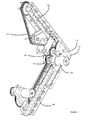
- FIG. 1illustrates one embodiment a machine equipped with a forklift apparatus.
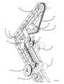
- FIG. 2illustrates an alternate view of a machine equipped with a forklift apparatus.
- FIGS. 3 , 4 and 5illustrate alternate perspective views of one embodiment of a forklift apparatus.
- FIG. 6illustrates a method for automatically moving a carriage into alignment with a target location.
- the present disclosurerelates generally to a machine for manipulating objects. It is understood, however, that the following disclosure provides many different embodiments, or examples, for implementing different features of the invention. Specific examples of components and arrangements are described below to simplify the present disclosure. These are, of course, merely examples and are not intended to be limiting.
- the forklift apparatus 102includes a lower mast 104 and an upper mast 106 .
- the lower mast 104has two substantial portions, a car guide 108 and a structural support beam 110 .
- the car guide 108is a front-facing, substantially flat plate and is coupled to the support beam 110 , which is a U-shaped beam.
- the structural support beam 110may be a box beam, I-beam, may comprise multiple beams, or may have any other suitable configuration.
- the car guide 108may be a pair of equally-spaced rails or any other suitable structure. And in still other embodiments, the car guide 108 may be entirely absent.
- the car guide 108 and the structural support beam 110are aluminum, but they may be made from any suitable material.
- the car guide 108 and the structural support beam 110may be another metal, including without limitation examples such as steel, iron, titanium, and tin; wood; plastic; or any combination thereof.
- the car guide 108may be coupled to the structural support beam 110 using any suitable technique, including for example threaded screws, nuts and bolts, welding, fusing, glue, or nails.
- the car guide 108 and the structural support beam 110may be cast or formed as a single integrated piece.
- the upper mast 106similarly includes a car guide 112 and a structural support beam 114 .
- the design of these upper mast 106 componentsis preferably the same as their counterparts in the lower mast.
- the upper mast 106couples to the lower mast 104 at a hinge 116 .
- the hinge 116includes a pin 118 that passes axially through apertures in the structural support beams 110 and 114 .
- the hinge 116provides an articulation point between the upper mast 106 and the lower mast 104 , allowing the upper mast 106 to rotate about the pin while the lower mast 104 remains relatively fixed in position. This articulation is further illustrated in the other figures.
- Affixed to the pin 118is an articulation gear 117 .
- a mast drive motorhas a mast drive gear that meshes with the articulation gear 117 to cause the upper mast 106 to rotate about the pin 118 . In this way, the upper mast 106 may be raised and lowered.
- the upper mast 106may be raised and lowered in other ways, including for example by one or more pneumatic or hydraulic cylinders, one or more springs, one or more chains or pulleys, one or more permanent or electro-magnets, or any combination thereof.
- the forklift apparatus 102further includes a carriage 120 that translates vertically along the car guides 108 and 112 .
- the carriage 120includes two carriage guides 122 and 124 that extend behind the car guides 108 and 112 on the opposite side of the carriage 120 .
- the carriage guides 122 and 124thus restrict the lateral movement of the carriage 120 and ensure that the carriage slides smoothly and only vertically.
- the carriage 120is equipped with an attachment 126 .
- the attachment 126includes two lower fixed prongs and an upper spring prong suitable for capturing and securing a horizontally oriented cylindrical object of appropriate size, such as a baton.
- the carriage 120may include other attachments, either in addition to or in place of the attachment 126 .
- Example attachmentsinclude sensors (including for example a magnetometer, microphone, or video or still image camera), traditional forklift forks, a grasping claw or clamp, a platform, a drum carrier, or any other suitable attachment.
- the attachment 126may be detachably attached to the carriage 120 via any suitable mechanism, including for example one or more screws, pins, bolts, latches, hooks, or any combination thereof.
- the carriage 120may include a plurality of coupling mechanisms or otherwise be equipped with a plurality of attachments 126 .
- the carriage 120is driven along the car guides 108 and 112 by a drive chain 128 .
- the drive chain 128is a substantially continuous roller chain formed from interlocking links.
- the carriage 120is preferably coupled to the drive chain 128 by a screw or bolt, but any other suitable coupling mechanism may also be used.
- the drive chain 128situated to slide along the surface of car guides 108 and 112 , although preferably the drive chain 128 minimal contact—or even no contact—with them.
- the drive chain 128engages with a sprocket 130 that is rotatably mounted to an axle 132 affixed to the upper structural support beam 114 .
- the sprocket 130may be affixed to the axle 132 which, in turn, is rotatably mounted to the upper structural support beam 114 .
- the sprocket 130has teeth sized to match the links of the drive chain 128 and may be a 24-tooth sprocket.
- the sprocket 130may rotate freely under the engagement of the drive chain 128 as the drive chain 128 moves the carriage 120 up and down the car guides 108 and 112 .
- the drive chain 128next engages with a tensioning sprocket 134 rotatably mounted on an axle 136 affixed to a tensioning lever 138 .
- the tensioning sprocket 134has teeth sized to match the links of the drive chain 128 and may be a 16-tooth sprocket.
- the tensioning lever 138is rotatably mounted to the upper structural support beam 114 using a pin hinge 140 .
- An elastically deformable loop 142has a first end that exerts a biasing force on the axle 136 , and inducing a torque on the tensioning lever 138 about the pin hinge 140 .
- the torque on the tensioning lever 138biases the tensioning sprocket 134 toward the drive chain 128 and away from the upper structural support beam 114 .
- the tensioning sprocket 134removes any excess slack in the drive chain 128 by lengthening the distance the drive chain 128 must traverse as it passes over the tensioning sprocket 134 .
- the elastically deformable loop 142has a second end coupled to a fixed mounting point 144 .
- the fixed mounting point 144is immovably affixed to the upper structural support beam 114 .
- the fixed mount point 144may be a point on the upper structural support beam 114 .
- the elastically deformable loop 142may be any suitable material and should be chosen to provide an appropriate level of tension on the drive chain 128 .
- the elastically deformable loop 142may be a rubber band of appropriate size and strength.
- the elastically deformable loop 142may be replaced with any other suitable biasing device, including, for example, a spring, pneumatic cylinder, or hydraulic cylinder.
- the drive chain 128next transits to a hinge sprocket 146 that is affixed to an axle 148 on a bracket 150 .
- the hinge sprocket 146has teeth sized to match the links of the drive chain 128 and may be a 24-tooth sprocket.
- the hinge sprocket 146may be rotatably mounted to the axle 148 , or the axle 148 may be rotatably mounted to the bracket 150 , or potentially both.
- the sprocket 146may rotate freely under the engagement of the drive chain 128 as the drive chain 128 moves the carriage 120 up and down the car guides 108 and 112 .
- the axle 148may also be mounted to a second bracket to provide improved support.
- the hinge sprocket 146may be rotatably mounted to the pin 118 .
- the sprocket 146may be replaced with two sprockets, one each mounted to upper and lower structural supports 144 and 110 near the hinge 116 .
- the path of the drive chain 128continues to a sprocket 152 at the lower extremus of the lower car guides 108 .
- the sprocket 152has teeth sized to match the links of the drive chain 128 and may be a 24-tooth sprocket.
- the sprocket 152is affixed to an axle that is further coupled to a gear 154 and chain drive motor 156 .
- the chain drive motor 156meshes with the gear 154 to provide motive force to the gear 154 .
- the gear 154which is affixed to the axle, transfers the motive force to the sprocket 152 , causing the sprocket 152 to rotate and thereby move the drive chain 128 in either direction.
- the chain drive motor 156is preferably a reversible DC drive motor, but any suitable type of motor may be used.
- the gear 154may be absent, and the chain drive motor 156 may couple directly to the axle.
- the chain drive motor 156may couple to the sprocket 152 through a gearbox that couples to the sprocket 152 or otherwise transfers rotational power to the sprocket 152 .
- the path of the drive chain 128continues along the surface of the lower car guide 108 and upper car guide 112 to the carriage 120 .
- the drive chain 128is a substantially continuous chain loop that is effective to transfer the rotational force provided by the chain drive motor to an axial force applied to the carriage 120 , thus inducing a vertical translation of the carriage 120 up and down the car guides 108 and 112 .
- the vertical position of carriage 120can be adjusted as desired for any activity.
- the forklift apparatus 102is mounted on a base 160 equipped with treads 162 .
- the treads 162allow the machine 100 to be driven over a variety of even, semi-even, and uneven surfaces.
- the base 160may alternatively be equipped with any suitable locomotion mechanism, including for example any number of wheels or legs.
- the base 160includes one or more suitable motors for driving the treads or other locomotion mechanism.
- the base 160may be fixed in place.
- the base 160further includes a control module 164 for controlling the operation of the forklift apparatus 102 and, optionally, the treads 162 or other locomotion mechanism.
- the control module 164produces one or more signals to control the operation of the chain drive motor and the mast drive motor.
- the control module 164may also provide control signals for other operations of the machine 100 .
- the control module 164may include a programmable processor and a computer-readable memory storing instructions that, when executed by the programmable processor, produce the one or more signals that control the operation of the chain drive motor and the mast drive motor.
- the computer-readable memorymay also be computer-writable.
- the control module 164may further include a plurality of input, output, or input/output ports. Thus, the control module 164 may also receive as input signals from one or more sensors located on or in the machine 100 .
- the control module 164includes a LEGO® MINDSTORMS® NXT Intelligent Brick available from the LEGO Group.
- the control module 164may further include one or more wired or wireless communications interfaces to allow for remote control and programming of the machine 100 .
- the control module 164may include an 802.11b wireless communications adapter.
- the control module 164includes a Samantha Wi-Fi (IEEE 802.11b) module available in the FIRST Tech Challenge program.
- the communications adaptermay use another protocol or medium, including for example ZigBee, Bluetooth, IEEE 802.11, radio frequency, infrared, microwave, sonic, electrical, optical, or any other communications protocol or medium.
- FIG. 2illustrated is the machine 100 in a different position as compared to FIG. 1 .
- the upper mast 106has been lowered by rotating about the hinge 116 .
- the drive chain 128remains suitably taut due to the dynamic tension adjustment provided by the tensioning sprocket 134 , tensioning lever 138 , and elastically deformable loop 142 .
- FIG. 2also illustrates the carriage 120 located on the lower car guide 108 . It is understood, however, that the carriage 120 may remain on the upper car guide 112 when the upper mast 106 is lowered.
- the articulation gear 117protrudes through an aperture in the lower car guide 108 .
- FIGS. 3 , 4 and 5illustrate alternate perspective views of one embodiment of a forklift apparatus. These figures further illustrate the mechanical features of the articulation point between the upper mast 106 and the lower mast 104 .
- the articulation gear 117is a generally large toothed wheel where a segment has been removed.
- the articulation gear 117may be formed by cutting a segment off of a complete gear, or it may be directly formed in the appropriate shape.
- the articulation gear 117is formed from an 120-tooth gear, that is, there would be 120 teeth on the articulation gear 117 except that there are in fact less because a segment and its corresponding teeth have been removed.
- the articulation gear 117meshes with a mast drive gear 302 that is mounted to a mast drive motor 304 .
- the mast drive gear 302is a 40-tooth gear, and thus the mast drive gear 302 and the articulation gear 117 provide a 3:1 drive ratio.
- the mast drive motor 304may be a reversible, 12-volt DC drive motor with a maximum speed of about 152 rpm. At maximum speed, the mast drive motor 304 makes about 2.5 revolutions per second, or one revolution in about 0.4 seconds.
- the mast drive motor 304begins from rest and thus does not immediately begin turning at 152 rpm.
- the mast drive motor 304may achieve a maximum speed of less than 152 rpm due to the load imposed on it in raising or lowering the upper mast 106 .
- the inventorshave found that in practice, the upper mast 106 may be readily raised or lowered in less than about 1 second.
- any suitable type of motormay be used, and the mast drive motor 304 may engage the articulation gear 117 through a gearbox.
- the speed of raising or lowering the upper mast 106may be faster or slower as may be desired for any particular application.
- the mast drive gear 302 and articulation gear 117may be replaced with suitable sprockets coupled by a chain.
- the mast drive motor 304alone provides sufficient braking force to maintain the upper mast 106 in any position.
- the upper mast 106may be stopped and held in any arbitrary position in between its raised and lowered positions. In some embodiments, however, it may be desirable (for safety or other considerations) to provide a mechanical support or brake to held the upper mast 106 in a position.
- the mast drive motor 302may be energized to provide a suitable force to counteract other forces, such as gravity, that may induce an undesirable movement of the upper mast 106 .
- the forklift apparatus 102may be equipped with one or more sensors, each of which may be of a similar or dissimilar type.
- the forklift apparatus 102may include a camera, microphone, or both.
- the upper mast 106may be equipped with a location sensor, which may operate to provide a signal indicative of the forklift apparatus 102 's position using either relative or absolute positioning.
- the location sensormay be a directional infrared sensor that detects the receipt of infrared energy transmitted by one or more fixed waypoints.
- the location sensormay be a GPS, GLONASS, or other suitable location sensor. The location sensor may provide one or more signals indicative of position to the control module 164 .
- Various components of the machine 100including for example at least some of the sprockets, the drive chain 128 , and the drive motors, may be obtained from the LEGO GROUP as part of their TETRIX line of robotic components.
- control modulepreferably includes a programmable processor and a computer-readable memory storing instructions executable by the processor.
- the control modulemay include an input allowing instructions for controlling the machine 100 to be received from a remote location.
- the inputmay be via any suitable input interface, including for example a Universal Serial Bus (USB), Bluetooth, or IEEE 802.11 interface.
- USBUniversal Serial Bus
- the machine 100may be remotely controlled through a wired or wireless connection.
- a threshold filtermay be applied to prevent initiating movement in response to a noise produced by the source of the instructions. For example, if the absolute value of the requested movement speed is less than a selected value, such as 10, then the requested movement may be discarded as unintentional noise.
- the control modulemay ignore a request to move the carriage 120 when the upper mast 106 is in the lowered position or is otherwise not in the raised position.
- the control modulemay include instructions allowing the machine 100 to operate autonomously.
- the instructionsmay include instructions for moving the carriage 120 in response to data provided by a sensor mounted on the carriage 120 .
- FIG. 6illustrates a method 600 for automatically moving the carriage 120 , when equipped with a magnetometer, into alignment with a target location identified by a magnetic field.
- the carriage 120may be equipped with one or more magnetometers to provide data indicative of the magnetic field near the carriage 120 .
- the method 600begins in step 602 .
- the carriageis initialized by moving the carriage to a known location, for example, to the top or bottom of the forklift apparatus. In some embodiments, the step 604 may be omitted.
- the magnetometer sensorsare initialized by clearing out any previously read values and preparing the sensors to take new readings.
- a measured valueis read from the magnetometer sensors. If the carriage 120 is equipped with multiple sensors, each sensor reading may be read sequentially. The measured values from the sensors may be stored in a array.
- the data obtained from the magnetometer sensorsis analyzed to determine whether one or more of the measured values indicates the presence of a magnetic field.
- each measured valueis compared to a threshold value, which may be predetermined.
- the threshold valuemay be selected to correspond to a magnetic field of a particular strength, for example, the strength of a magnetic field within about 2 to 3 inches from a given type of magnet. In other embodiments, other forms of data analysis may be performed.
- step 612it is determined whether the data analysis performed in step 610 indicates that a magnet has been found. If no magnet has been found, then the process proceeds to step 614 , where the carriage is moved.
- the carriagemay be moved in a uniform direction a predetermined distance or for a predetermined amount of time, although other possibilities are also contemplated.
- the carriagemay be moved, for example, by activating the carriage drive motor to turn a sprocket engaged with the drive chain. After the carriage has been moved, the process returns to step 608 .
- the steps 608 to 614may occur simultaneously, such that data from the magnetometer sensors is substantially continuously analyzed as the carriage moves in a uniform direction.
- step 612If in step 612 it is determined that a magnet has been detected, then the process proceeds to step 616 , where the process ends.
- the carriagemay be automatically aligned with a target location identified by a magnet producing a magnetic field.
- other types of sensorsmay be used, including for example, sensors providing indications of light, sound, distance, or temperature.
- the method 600may be readily used with these other types of sensors to similarly automatically align the carriage with a target location identified by measurements taken from such sensors.
- the forklift apparatushas been described relative to a preferred embodiment. Improvements or modifications that become apparent to persons of ordinary skill in the art only after reading this disclosure are deemed within the spirit and scope of the application.
- the forklift apparatushas been described as having a generally vertical orientation, but it is understood that the forklift apparatus may alternatively be mounted in a horizontal, inverted, or any other orientation.
Landscapes
- Engineering & Computer Science (AREA)
- Transportation (AREA)
- Structural Engineering (AREA)
- Civil Engineering (AREA)
- Life Sciences & Earth Sciences (AREA)
- Geology (AREA)
- Mechanical Engineering (AREA)
- Chemical & Material Sciences (AREA)
- Combustion & Propulsion (AREA)
- Forklifts And Lifting Vehicles (AREA)
Abstract
Description
Claims (18)
Priority Applications (1)
| Application Number | Priority Date | Filing Date | Title |
|---|---|---|---|
| US13/175,474US8794386B2 (en) | 2011-07-01 | 2011-07-01 | Folding forklift |
Applications Claiming Priority (1)
| Application Number | Priority Date | Filing Date | Title |
|---|---|---|---|
| US13/175,474US8794386B2 (en) | 2011-07-01 | 2011-07-01 | Folding forklift |
Publications (2)
| Publication Number | Publication Date |
|---|---|
| US20130006444A1 US20130006444A1 (en) | 2013-01-03 |
| US8794386B2true US8794386B2 (en) | 2014-08-05 |
Family
ID=47391407
Family Applications (1)
| Application Number | Title | Priority Date | Filing Date |
|---|---|---|---|
| US13/175,474Active - Reinstated2032-02-13US8794386B2 (en) | 2011-07-01 | 2011-07-01 | Folding forklift |
Country Status (1)
| Country | Link |
|---|---|
| US (1) | US8794386B2 (en) |
Cited By (7)
| Publication number | Priority date | Publication date | Assignee | Title |
|---|---|---|---|---|
| US20150239720A1 (en)* | 2014-02-25 | 2015-08-27 | Kion Warehouse Systems Gmbh | Industrial Truck |
| US20180290865A1 (en)* | 2015-05-14 | 2018-10-11 | George J. Banks | Small Engine Transporter Device |
| US10647351B2 (en) | 2016-12-07 | 2020-05-12 | Cardinal Gibbons High School | Robotic platform with wheeled legs and virtual differential transmission |
| US11167425B2 (en)* | 2014-10-28 | 2021-11-09 | Festo Se & Co. Kg | Universal end of arm robot tool |
| US11351676B2 (en) | 2019-09-17 | 2022-06-07 | Cardinal Gibbons High School | Self-lifting robot with automatic release and multi-jointed arm |
| US20220379792A1 (en)* | 2021-05-25 | 2022-12-01 | Stratom, Inc. | Cargo transport system |
| US12128145B2 (en) | 2021-02-08 | 2024-10-29 | Cardinal Gibbons High School | Decontamination robot with swerve drive and scissor lift |
Families Citing this family (4)
| Publication number | Priority date | Publication date | Assignee | Title |
|---|---|---|---|---|
| CN105692502A (en)* | 2016-04-26 | 2016-06-22 | 肇庆市森美金属有限公司 | Automatic sheet loader with identification function |
| US10472006B2 (en) | 2016-09-12 | 2019-11-12 | Steven Borntrager | Powered hand truck with pivoting tracks |
| US10346797B2 (en)* | 2016-09-26 | 2019-07-09 | Cybernet Systems, Inc. | Path and load localization and operations supporting automated warehousing using robotic forklifts or other material handling vehicles |
| IT201700022838A1 (en)* | 2017-03-01 | 2018-09-01 | Gruppo Tecnoferrari Spa | Automatic guided vehicle. |
Citations (66)
| Publication number | Priority date | Publication date | Assignee | Title |
|---|---|---|---|---|
| US2176731A (en)* | 1937-01-25 | 1939-10-17 | Int Stacey Corp | Folding mast for portable well drilling and operating apparatus |
| US3666123A (en)* | 1971-01-20 | 1972-05-30 | Harold Tornheim | Tailgate cargo lifting apparatus for the rear end of a truck |
| US3727781A (en)* | 1967-08-15 | 1973-04-17 | Knickerbocker Co | Lift truck load lifting mechanism |
| US3782571A (en)* | 1972-04-24 | 1974-01-01 | Towmotor Corp | Lift truck mast-mounting arrangement |
| US4016992A (en)* | 1974-05-30 | 1977-04-12 | Raygo Wagner, Inc. | Lift truck with rotatable load-handling apparatus |
| US4354795A (en)* | 1981-02-13 | 1982-10-19 | Dutra Jr Joseph G | Load stabilizer assembly with pivotal mount for a forklift truck |
| US4365921A (en)* | 1979-06-21 | 1982-12-28 | Brouwer Turf Equipment Limited | Forklift vehicle |
| US4371046A (en)* | 1980-04-21 | 1983-02-01 | Vernon Read | Apparatus for and method of drilling a hole into the ground |
| US4431083A (en)* | 1980-10-20 | 1984-02-14 | Caterpillar Tractor Co. | Apparatus for lifting a member using parallelogram mounted links |
| US4476960A (en)* | 1982-08-09 | 1984-10-16 | Towmotor Corporation | Adjustable chain anchor for lift trucks |
| US4493604A (en)* | 1982-10-14 | 1985-01-15 | Taylor Machine Works, Inc. | Fork lift clamp apparatus |
| US4571139A (en)* | 1981-08-24 | 1986-02-18 | Superior Handling Equipment, Inc. | Self-propelled freight handling truck |
| US4619346A (en)* | 1983-07-11 | 1986-10-28 | Comabi S.A. | Elevator-type work platform |
| US4826474A (en)* | 1987-12-14 | 1989-05-02 | Butterworth Jetting Systems, Inc. | Forklift apparatus for unloading articles from an elevated surface |
| US5180275A (en)* | 1991-05-28 | 1993-01-19 | The Braun Corporation | Rotary bus lift with power stowable platform |
| US5328321A (en)* | 1991-09-05 | 1994-07-12 | Moffett Research And Development Limited | Multi-stage mast for a forklift truck |
| US5370494A (en)* | 1993-07-13 | 1994-12-06 | Holmes; Arthur J. | Self-propelled lift truck |
| US5451135A (en)* | 1993-04-02 | 1995-09-19 | Carnegie Mellon University | Collapsible mobile vehicle |
| US5651658A (en)* | 1993-07-13 | 1997-07-29 | Holmes; Arthur Jack | Articulated lift truck |
| US5697755A (en)* | 1995-03-03 | 1997-12-16 | Mccauley; Charles A. | Forklift level indicator |
| US5758785A (en)* | 1995-06-22 | 1998-06-02 | Spinosa; Dominic | Lifting system |
| US6010299A (en)* | 1998-05-08 | 2000-01-04 | Jesswein; Ronald M. | Lifting and positioning device |
| US6029779A (en)* | 1997-11-13 | 2000-02-29 | Upright, Inc. | Automatic parking brake and steering spindle |
| US6092976A (en)* | 1997-12-11 | 2000-07-25 | Kabushiki Kaisha Toyoda Jidoshokki Seisakusho | Delayed-action empty-seat safety interlock for forklift controls |
| US6209913B1 (en)* | 1997-12-04 | 2001-04-03 | Kabushiki Kaisha Toyoda Jidoshokki Seisakusho | Axle pivot control apparatus for industrial vehicles |
| US6296081B1 (en)* | 1998-04-10 | 2001-10-02 | Kabushiki Kaisha Toyoda Jidoshokki Seisakusho | Lift cylinder and mast assembly of forklift |
| US20020117607A1 (en)* | 2001-02-26 | 2002-08-29 | L.A. Goddard | Visible light forklift alignment apparatus |
| US20020134970A1 (en)* | 2001-02-22 | 2002-09-26 | Eric Bressner | Portable and demountable lifting device |
| US20020189871A1 (en)* | 1998-03-27 | 2002-12-19 | Irobot Corporation, A Delaware Corporation | Robotic platform |
| US6547217B1 (en)* | 2000-09-13 | 2003-04-15 | Pcc Superior Fabrication | Variable reach lift arm |
| US20040076501A1 (en)* | 2000-12-04 | 2004-04-22 | Mcgill Dennis E. | Apparatus for lifting and moving a workload |
| US20040101392A1 (en)* | 2002-09-06 | 2004-05-27 | Drake Peter Anthony | Forklift trucks |
| US20040169167A1 (en)* | 2003-02-13 | 2004-09-02 | Hal Reinelt | Mobile engine lift apparatus |
| US20040226762A1 (en)* | 2003-05-14 | 2004-11-18 | Sebastian Huther | Fork-lift reach truck |
| US20050036864A1 (en)* | 2003-05-30 | 2005-02-17 | Eric O' Keeffe | Truck mounted forklift with double-acting freelift mast |
| US20050220588A1 (en)* | 2003-11-17 | 2005-10-06 | Kevin Turnbull | Forklifts |
| US20050265813A1 (en)* | 2004-06-01 | 2005-12-01 | Marrell Haney | Transport vehicle with lifting devices |
| US20060045708A1 (en)* | 2004-08-05 | 2006-03-02 | Bain Colin C | Patient lift with three-point vertical stance |
| US20060096941A1 (en)* | 2004-11-08 | 2006-05-11 | Erwin Stoetzer | Construction device comprising a mast having a pivotable deflecting device |
| US20060255954A1 (en)* | 2005-05-13 | 2006-11-16 | Ems Technologies, Inc. | Radio frequency identification (RFID) system for a forklift |
| US20070140817A1 (en)* | 2004-03-15 | 2007-06-21 | Rudolf Hansl | Computer-controlled transport device |
| US20070166138A1 (en)* | 2006-01-18 | 2007-07-19 | Brooks Brady B | Truck Mounted Multifunction Lifting System and Method |
| US20070243052A1 (en)* | 2006-03-27 | 2007-10-18 | Kubota Corporation | Loader work apparatus |
| US20080044265A1 (en)* | 2006-08-17 | 2008-02-21 | Steven Borntrager | Powered hand truck |
| US20080060880A1 (en)* | 2006-09-07 | 2008-03-13 | Gerhard Finkbeiner | Load suspension means for a lifting apparatus |
| US20080116013A1 (en)* | 2004-06-18 | 2008-05-22 | Vandewinckel Stephen C | High Lift Truck |
| US20080184840A1 (en)* | 2007-02-07 | 2008-08-07 | Avishay Novoplanski | Unmanned robot vehicle with mobility enhancing arm |
| US20080297590A1 (en)* | 2007-05-31 | 2008-12-04 | Barber Fred | 3-d robotic vision and vision control system |
| US20090020368A1 (en)* | 2007-07-05 | 2009-01-22 | Jungheinrich Aktiengesellschaft | Industrial truck, especially fork lift |
| US20090188038A1 (en)* | 2008-01-28 | 2009-07-30 | Terry Raney | Storable dual action hydraulic lifting device |
| US20090294218A1 (en)* | 2008-05-27 | 2009-12-03 | Geoffrey Archer | Bomb disposal robot having a forklift capability and method |
| US20100068024A1 (en)* | 2008-09-18 | 2010-03-18 | Agens Michael W | Remotely controlled robots having improved tool deployment systems |
| US7689394B2 (en)* | 2003-08-26 | 2010-03-30 | Siemens Industry, Inc. | System and method for remotely analyzing machine performance |
| US20100106344A1 (en)* | 2008-10-27 | 2010-04-29 | Edwards Dean B | Unmanned land vehicle having universal interfaces for attachments and autonomous operation capabilities and method of operation thereof |
| US20100122651A1 (en)* | 2008-11-18 | 2010-05-20 | Borum Paul W | Lift apparatus for a watercraft |
| US7748900B2 (en)* | 2006-07-11 | 2010-07-06 | Siemens Aktiengesellschaft | X-ray system with an industrial robot |
| US20100183412A1 (en)* | 2006-08-17 | 2010-07-22 | Steven Borntrager | Powered hand truck |
| US20100263948A1 (en)* | 2006-10-06 | 2010-10-21 | Couture Adam P | Robotic vehicle |
| US20100294594A1 (en)* | 2006-03-22 | 2010-11-25 | Jlg Industries, Inc. | Mast Lift and Mast Lift System |
| US20110155483A1 (en)* | 2006-10-06 | 2011-06-30 | Couture Adam P | Robotic vehicle deck adjustment |
| US7974736B2 (en)* | 2007-04-05 | 2011-07-05 | Foster-Miller, Inc. | Robot deployed weapon system and safing method |
| US8176808B2 (en)* | 2007-09-13 | 2012-05-15 | Foster-Miller, Inc. | Robot arm assembly |
| US20120228064A1 (en)* | 2011-03-11 | 2012-09-13 | LiftSmart, LLC | Cam driven wedge braking system for multi-stage lifts |
| US20120255810A1 (en)* | 2011-04-11 | 2012-10-11 | Yang Chih-Hsiung | Unmanned trackless order picking forklift system |
| US20120263565A1 (en)* | 2009-09-18 | 2012-10-18 | O'keeffe Eric | linkage system for a forklift truck |
| US8583313B2 (en)* | 2008-09-19 | 2013-11-12 | International Electronic Machines Corp. | Robotic vehicle for performing rail-related actions |
- 2011
- 2011-07-01USUS13/175,474patent/US8794386B2/enactiveActive - Reinstated
Patent Citations (70)
| Publication number | Priority date | Publication date | Assignee | Title |
|---|---|---|---|---|
| US2176731A (en)* | 1937-01-25 | 1939-10-17 | Int Stacey Corp | Folding mast for portable well drilling and operating apparatus |
| US3727781A (en)* | 1967-08-15 | 1973-04-17 | Knickerbocker Co | Lift truck load lifting mechanism |
| US3666123A (en)* | 1971-01-20 | 1972-05-30 | Harold Tornheim | Tailgate cargo lifting apparatus for the rear end of a truck |
| US3782571A (en)* | 1972-04-24 | 1974-01-01 | Towmotor Corp | Lift truck mast-mounting arrangement |
| US4016992A (en)* | 1974-05-30 | 1977-04-12 | Raygo Wagner, Inc. | Lift truck with rotatable load-handling apparatus |
| US4365921A (en)* | 1979-06-21 | 1982-12-28 | Brouwer Turf Equipment Limited | Forklift vehicle |
| US4371046A (en)* | 1980-04-21 | 1983-02-01 | Vernon Read | Apparatus for and method of drilling a hole into the ground |
| US4431083A (en)* | 1980-10-20 | 1984-02-14 | Caterpillar Tractor Co. | Apparatus for lifting a member using parallelogram mounted links |
| US4354795A (en)* | 1981-02-13 | 1982-10-19 | Dutra Jr Joseph G | Load stabilizer assembly with pivotal mount for a forklift truck |
| US4571139A (en)* | 1981-08-24 | 1986-02-18 | Superior Handling Equipment, Inc. | Self-propelled freight handling truck |
| US4476960A (en)* | 1982-08-09 | 1984-10-16 | Towmotor Corporation | Adjustable chain anchor for lift trucks |
| US4493604A (en)* | 1982-10-14 | 1985-01-15 | Taylor Machine Works, Inc. | Fork lift clamp apparatus |
| US4619346A (en)* | 1983-07-11 | 1986-10-28 | Comabi S.A. | Elevator-type work platform |
| US4826474A (en)* | 1987-12-14 | 1989-05-02 | Butterworth Jetting Systems, Inc. | Forklift apparatus for unloading articles from an elevated surface |
| US5180275A (en)* | 1991-05-28 | 1993-01-19 | The Braun Corporation | Rotary bus lift with power stowable platform |
| US5328321A (en)* | 1991-09-05 | 1994-07-12 | Moffett Research And Development Limited | Multi-stage mast for a forklift truck |
| US5451135A (en)* | 1993-04-02 | 1995-09-19 | Carnegie Mellon University | Collapsible mobile vehicle |
| US5370494A (en)* | 1993-07-13 | 1994-12-06 | Holmes; Arthur J. | Self-propelled lift truck |
| US5651658A (en)* | 1993-07-13 | 1997-07-29 | Holmes; Arthur Jack | Articulated lift truck |
| US5697755A (en)* | 1995-03-03 | 1997-12-16 | Mccauley; Charles A. | Forklift level indicator |
| US5758785A (en)* | 1995-06-22 | 1998-06-02 | Spinosa; Dominic | Lifting system |
| US6029779A (en)* | 1997-11-13 | 2000-02-29 | Upright, Inc. | Automatic parking brake and steering spindle |
| US6209913B1 (en)* | 1997-12-04 | 2001-04-03 | Kabushiki Kaisha Toyoda Jidoshokki Seisakusho | Axle pivot control apparatus for industrial vehicles |
| US6092976A (en)* | 1997-12-11 | 2000-07-25 | Kabushiki Kaisha Toyoda Jidoshokki Seisakusho | Delayed-action empty-seat safety interlock for forklift controls |
| US20020189871A1 (en)* | 1998-03-27 | 2002-12-19 | Irobot Corporation, A Delaware Corporation | Robotic platform |
| US6296081B1 (en)* | 1998-04-10 | 2001-10-02 | Kabushiki Kaisha Toyoda Jidoshokki Seisakusho | Lift cylinder and mast assembly of forklift |
| US6010299A (en)* | 1998-05-08 | 2000-01-04 | Jesswein; Ronald M. | Lifting and positioning device |
| US6547217B1 (en)* | 2000-09-13 | 2003-04-15 | Pcc Superior Fabrication | Variable reach lift arm |
| US20040076501A1 (en)* | 2000-12-04 | 2004-04-22 | Mcgill Dennis E. | Apparatus for lifting and moving a workload |
| US20070292252A1 (en)* | 2000-12-04 | 2007-12-20 | Mcgill Dennis E | Apparatus for lifting and moving a workload |
| US20020134970A1 (en)* | 2001-02-22 | 2002-09-26 | Eric Bressner | Portable and demountable lifting device |
| US20020117607A1 (en)* | 2001-02-26 | 2002-08-29 | L.A. Goddard | Visible light forklift alignment apparatus |
| US20040101392A1 (en)* | 2002-09-06 | 2004-05-27 | Drake Peter Anthony | Forklift trucks |
| US20040169167A1 (en)* | 2003-02-13 | 2004-09-02 | Hal Reinelt | Mobile engine lift apparatus |
| US20040226762A1 (en)* | 2003-05-14 | 2004-11-18 | Sebastian Huther | Fork-lift reach truck |
| US20050036864A1 (en)* | 2003-05-30 | 2005-02-17 | Eric O' Keeffe | Truck mounted forklift with double-acting freelift mast |
| US7689394B2 (en)* | 2003-08-26 | 2010-03-30 | Siemens Industry, Inc. | System and method for remotely analyzing machine performance |
| US20050220588A1 (en)* | 2003-11-17 | 2005-10-06 | Kevin Turnbull | Forklifts |
| US20070140817A1 (en)* | 2004-03-15 | 2007-06-21 | Rudolf Hansl | Computer-controlled transport device |
| US20050265813A1 (en)* | 2004-06-01 | 2005-12-01 | Marrell Haney | Transport vehicle with lifting devices |
| US20080116013A1 (en)* | 2004-06-18 | 2008-05-22 | Vandewinckel Stephen C | High Lift Truck |
| US20060045708A1 (en)* | 2004-08-05 | 2006-03-02 | Bain Colin C | Patient lift with three-point vertical stance |
| US20060096941A1 (en)* | 2004-11-08 | 2006-05-11 | Erwin Stoetzer | Construction device comprising a mast having a pivotable deflecting device |
| US20060255954A1 (en)* | 2005-05-13 | 2006-11-16 | Ems Technologies, Inc. | Radio frequency identification (RFID) system for a forklift |
| US20070166138A1 (en)* | 2006-01-18 | 2007-07-19 | Brooks Brady B | Truck Mounted Multifunction Lifting System and Method |
| US20100294594A1 (en)* | 2006-03-22 | 2010-11-25 | Jlg Industries, Inc. | Mast Lift and Mast Lift System |
| US20070243052A1 (en)* | 2006-03-27 | 2007-10-18 | Kubota Corporation | Loader work apparatus |
| US7748900B2 (en)* | 2006-07-11 | 2010-07-06 | Siemens Aktiengesellschaft | X-ray system with an industrial robot |
| US8186931B2 (en)* | 2006-08-17 | 2012-05-29 | Steven Borntrager | Powered hand truck |
| US20080044265A1 (en)* | 2006-08-17 | 2008-02-21 | Steven Borntrager | Powered hand truck |
| US20090041564A1 (en)* | 2006-08-17 | 2009-02-12 | Steven Borntrager | Powered hand truck |
| US20100183412A1 (en)* | 2006-08-17 | 2010-07-22 | Steven Borntrager | Powered hand truck |
| US7704035B2 (en)* | 2006-08-17 | 2010-04-27 | Steven Borntrager | Powered hand truck |
| US20080060880A1 (en)* | 2006-09-07 | 2008-03-13 | Gerhard Finkbeiner | Load suspension means for a lifting apparatus |
| US20100263948A1 (en)* | 2006-10-06 | 2010-10-21 | Couture Adam P | Robotic vehicle |
| US20110155483A1 (en)* | 2006-10-06 | 2011-06-30 | Couture Adam P | Robotic vehicle deck adjustment |
| US20080184840A1 (en)* | 2007-02-07 | 2008-08-07 | Avishay Novoplanski | Unmanned robot vehicle with mobility enhancing arm |
| US7974736B2 (en)* | 2007-04-05 | 2011-07-05 | Foster-Miller, Inc. | Robot deployed weapon system and safing method |
| US20080297590A1 (en)* | 2007-05-31 | 2008-12-04 | Barber Fred | 3-d robotic vision and vision control system |
| US20090020368A1 (en)* | 2007-07-05 | 2009-01-22 | Jungheinrich Aktiengesellschaft | Industrial truck, especially fork lift |
| US8176808B2 (en)* | 2007-09-13 | 2012-05-15 | Foster-Miller, Inc. | Robot arm assembly |
| US20090188038A1 (en)* | 2008-01-28 | 2009-07-30 | Terry Raney | Storable dual action hydraulic lifting device |
| US20090294218A1 (en)* | 2008-05-27 | 2009-12-03 | Geoffrey Archer | Bomb disposal robot having a forklift capability and method |
| US20100068024A1 (en)* | 2008-09-18 | 2010-03-18 | Agens Michael W | Remotely controlled robots having improved tool deployment systems |
| US8583313B2 (en)* | 2008-09-19 | 2013-11-12 | International Electronic Machines Corp. | Robotic vehicle for performing rail-related actions |
| US20100106344A1 (en)* | 2008-10-27 | 2010-04-29 | Edwards Dean B | Unmanned land vehicle having universal interfaces for attachments and autonomous operation capabilities and method of operation thereof |
| US20100122651A1 (en)* | 2008-11-18 | 2010-05-20 | Borum Paul W | Lift apparatus for a watercraft |
| US20120263565A1 (en)* | 2009-09-18 | 2012-10-18 | O'keeffe Eric | linkage system for a forklift truck |
| US20120228064A1 (en)* | 2011-03-11 | 2012-09-13 | LiftSmart, LLC | Cam driven wedge braking system for multi-stage lifts |
| US20120255810A1 (en)* | 2011-04-11 | 2012-10-11 | Yang Chih-Hsiung | Unmanned trackless order picking forklift system |
Cited By (9)
| Publication number | Priority date | Publication date | Assignee | Title |
|---|---|---|---|---|
| US20150239720A1 (en)* | 2014-02-25 | 2015-08-27 | Kion Warehouse Systems Gmbh | Industrial Truck |
| US9783400B2 (en)* | 2014-02-25 | 2017-10-10 | Kion Warehouse Systems Gmbh | Industrial truck |
| US11167425B2 (en)* | 2014-10-28 | 2021-11-09 | Festo Se & Co. Kg | Universal end of arm robot tool |
| US20180290865A1 (en)* | 2015-05-14 | 2018-10-11 | George J. Banks | Small Engine Transporter Device |
| US10647351B2 (en) | 2016-12-07 | 2020-05-12 | Cardinal Gibbons High School | Robotic platform with wheeled legs and virtual differential transmission |
| US11351676B2 (en) | 2019-09-17 | 2022-06-07 | Cardinal Gibbons High School | Self-lifting robot with automatic release and multi-jointed arm |
| US12128145B2 (en) | 2021-02-08 | 2024-10-29 | Cardinal Gibbons High School | Decontamination robot with swerve drive and scissor lift |
| US20220379792A1 (en)* | 2021-05-25 | 2022-12-01 | Stratom, Inc. | Cargo transport system |
| US20230191978A1 (en)* | 2021-05-25 | 2023-06-22 | Stratom, Inc. | Cargo transport system |
Also Published As
| Publication number | Publication date |
|---|---|
| US20130006444A1 (en) | 2013-01-03 |
Similar Documents
| Publication | Publication Date | Title |
|---|---|---|
| US8794386B2 (en) | Folding forklift | |
| JP6568086B2 (en) | Lifting crane with improved movable counterweight | |
| US7467723B2 (en) | Electric motor driven traversing balancer hoist | |
| US8813981B2 (en) | Anti-two block system for a crane assembly | |
| AU2010237171B2 (en) | Lift hand truck | |
| US20170335579A1 (en) | Universal screw-driving machine support for a plate-lifting tool, tool equipped with this support, and implementation method | |
| JP2017060286A (en) | Overhead wire inspection device | |
| KR20100089210A (en) | Multipurpose lift device for move style | |
| US20220297990A1 (en) | Lifting and transport device | |
| US20180111752A1 (en) | Powered lifting device | |
| US20150123059A1 (en) | Lifting devices | |
| CN113023557B (en) | Self-clamping clamp, loading and unloading device and method for using the self-clamping clamp | |
| CN102234086B (en) | Rudderstock for ground transmission machine operated by rudderstock | |
| KR102097162B1 (en) | Steerable and external mounted type block lifter | |
| CN202829333U (en) | Tilt rotation driving mechanism and crane | |
| CN118387749B (en) | Die lifting device for forging trailer hook | |
| KR101610928B1 (en) | Magnetic lift device for rotation of heavyweight object | |
| AU2009201532A1 (en) | Clamping Device for Lifting Slab, Panel or Sheet Material | |
| CN220243322U (en) | Intelligent logistics placing vehicle | |
| JP4331962B2 (en) | Mobile device for work equipment | |
| WO2008130229A1 (en) | Lifting device for a vehicle | |
| KR20140137938A (en) | Crane apparatus for vehicle | |
| KR20140098623A (en) | Lift device | |
| JPS5849322Y2 (en) | Work stage with trolley device | |
| JPS621192Y2 (en) |
Legal Events
| Date | Code | Title | Description |
|---|---|---|---|
| AS | Assignment | Owner name:CARDINAL GIBBONS HIGH SCHOOL, NORTH CAROLINA Free format text:ASSIGNMENT OF ASSIGNORS INTEREST;ASSIGNORS:KEELING, ARIANA;LANIER, SEAN;DYER, SARAH;AND OTHERS;SIGNING DATES FROM 20110624 TO 20110626;REEL/FRAME:026538/0293 | |
| STCF | Information on status: patent grant | Free format text:PATENTED CASE | |
| FEPP | Fee payment procedure | Free format text:MAINTENANCE FEE REMINDER MAILED (ORIGINAL EVENT CODE: REM.) | |
| FEPP | Fee payment procedure | Free format text:SURCHARGE FOR LATE PAYMENT, SMALL ENTITY (ORIGINAL EVENT CODE: M2554) | |
| MAFP | Maintenance fee payment | Free format text:PAYMENT OF MAINTENANCE FEE, 4TH YR, SMALL ENTITY (ORIGINAL EVENT CODE: M2551) Year of fee payment:4 | |
| FEPP | Fee payment procedure | Free format text:MAINTENANCE FEE REMINDER MAILED (ORIGINAL EVENT CODE: REM.); ENTITY STATUS OF PATENT OWNER: SMALL ENTITY | |
| LAPS | Lapse for failure to pay maintenance fees | Free format text:PATENT EXPIRED FOR FAILURE TO PAY MAINTENANCE FEES (ORIGINAL EVENT CODE: EXP.); ENTITY STATUS OF PATENT OWNER: SMALL ENTITY | |
| STCH | Information on status: patent discontinuation | Free format text:PATENT EXPIRED DUE TO NONPAYMENT OF MAINTENANCE FEES UNDER 37 CFR 1.362 | |
| FP | Lapsed due to failure to pay maintenance fee | Effective date:20220805 | |
| PRDP | Patent reinstated due to the acceptance of a late maintenance fee | Effective date:20230127 | |
| FEPP | Fee payment procedure | Free format text:PETITION RELATED TO MAINTENANCE FEES FILED (ORIGINAL EVENT CODE: PMFP); ENTITY STATUS OF PATENT OWNER: SMALL ENTITY Free format text:PETITION RELATED TO MAINTENANCE FEES GRANTED (ORIGINAL EVENT CODE: PMFG); ENTITY STATUS OF PATENT OWNER: SMALL ENTITY Free format text:SURCHARGE, PETITION TO ACCEPT PYMT AFTER EXP, UNINTENTIONAL. (ORIGINAL EVENT CODE: M2558); ENTITY STATUS OF PATENT OWNER: SMALL ENTITY | |
| MAFP | Maintenance fee payment | Free format text:PAYMENT OF MAINTENANCE FEE, 8TH YR, SMALL ENTITY (ORIGINAL EVENT CODE: M2552); ENTITY STATUS OF PATENT OWNER: SMALL ENTITY Year of fee payment:8 | |
| STCF | Information on status: patent grant | Free format text:PATENTED CASE |