US8794002B2 - Thermal energy conversion method - Google Patents
Thermal energy conversion methodDownload PDFInfo
- Publication number
- US8794002B2 US8794002B2US12/631,400US63140009AUS8794002B2US 8794002 B2US8794002 B2US 8794002B2US 63140009 AUS63140009 AUS 63140009AUS 8794002 B2US8794002 B2US 8794002B2
- Authority
- US
- United States
- Prior art keywords
- working fluid
- controlling
- fluid circuit
- pressure side
- circuit
- Prior art date
- Legal status (The legal status is an assumption and is not a legal conclusion. Google has not performed a legal analysis and makes no representation as to the accuracy of the status listed.)
- Active, expires
Links
Images


Classifications
- F—MECHANICAL ENGINEERING; LIGHTING; HEATING; WEAPONS; BLASTING
- F01—MACHINES OR ENGINES IN GENERAL; ENGINE PLANTS IN GENERAL; STEAM ENGINES
- F01K—STEAM ENGINE PLANTS; STEAM ACCUMULATORS; ENGINE PLANTS NOT OTHERWISE PROVIDED FOR; ENGINES USING SPECIAL WORKING FLUIDS OR CYCLES
- F01K25/00—Plants or engines characterised by use of special working fluids, not otherwise provided for; Plants operating in closed cycles and not otherwise provided for
- F01K25/08—Plants or engines characterised by use of special working fluids, not otherwise provided for; Plants operating in closed cycles and not otherwise provided for using special vapours
- F01K25/10—Plants or engines characterised by use of special working fluids, not otherwise provided for; Plants operating in closed cycles and not otherwise provided for using special vapours the vapours being cold, e.g. ammonia, carbon dioxide, ether
- F01K25/103—Carbon dioxide
- F—MECHANICAL ENGINEERING; LIGHTING; HEATING; WEAPONS; BLASTING
- F01—MACHINES OR ENGINES IN GENERAL; ENGINE PLANTS IN GENERAL; STEAM ENGINES
- F01K—STEAM ENGINE PLANTS; STEAM ACCUMULATORS; ENGINE PLANTS NOT OTHERWISE PROVIDED FOR; ENGINES USING SPECIAL WORKING FLUIDS OR CYCLES
- F01K3/00—Plants characterised by the use of steam or heat accumulators, or intermediate steam heaters, therein
- F01K3/18—Plants characterised by the use of steam or heat accumulators, or intermediate steam heaters, therein having heaters
- F01K3/185—Plants characterised by the use of steam or heat accumulators, or intermediate steam heaters, therein having heaters using waste heat from outside the plant
- F—MECHANICAL ENGINEERING; LIGHTING; HEATING; WEAPONS; BLASTING
- F01—MACHINES OR ENGINES IN GENERAL; ENGINE PLANTS IN GENERAL; STEAM ENGINES
- F01K—STEAM ENGINE PLANTS; STEAM ACCUMULATORS; ENGINE PLANTS NOT OTHERWISE PROVIDED FOR; ENGINES USING SPECIAL WORKING FLUIDS OR CYCLES
- F01K3/00—Plants characterised by the use of steam or heat accumulators, or intermediate steam heaters, therein
- F01K3/18—Plants characterised by the use of steam or heat accumulators, or intermediate steam heaters, therein having heaters
- F01K3/186—Plants characterised by the use of steam or heat accumulators, or intermediate steam heaters, therein having heaters using electric heat
- F—MECHANICAL ENGINEERING; LIGHTING; HEATING; WEAPONS; BLASTING
- F01—MACHINES OR ENGINES IN GENERAL; ENGINE PLANTS IN GENERAL; STEAM ENGINES
- F01K—STEAM ENGINE PLANTS; STEAM ACCUMULATORS; ENGINE PLANTS NOT OTHERWISE PROVIDED FOR; ENGINES USING SPECIAL WORKING FLUIDS OR CYCLES
- F01K7/00—Steam engine plants characterised by the use of specific types of engine; Plants or engines characterised by their use of special steam systems, cycles or processes; Control means specially adapted for such systems, cycles or processes; Use of withdrawn or exhaust steam for feed-water heating
- F01K7/16—Steam engine plants characterised by the use of specific types of engine; Plants or engines characterised by their use of special steam systems, cycles or processes; Control means specially adapted for such systems, cycles or processes; Use of withdrawn or exhaust steam for feed-water heating the engines being only of turbine type
- F01K7/165—Controlling means specially adapted therefor
- F—MECHANICAL ENGINEERING; LIGHTING; HEATING; WEAPONS; BLASTING
- F24—HEATING; RANGES; VENTILATING
- F24H—FLUID HEATERS, e.g. WATER OR AIR HEATERS, HAVING HEAT-GENERATING MEANS, e.g. HEAT PUMPS, IN GENERAL
- F24H2240/00—Fluid heaters having electrical generators
- F24H2240/12—Fluid heaters having electrical generators with thermodynamic cycle for converting thermal energy to mechanical power to produce electrical energy
- Y—GENERAL TAGGING OF NEW TECHNOLOGICAL DEVELOPMENTS; GENERAL TAGGING OF CROSS-SECTIONAL TECHNOLOGIES SPANNING OVER SEVERAL SECTIONS OF THE IPC; TECHNICAL SUBJECTS COVERED BY FORMER USPC CROSS-REFERENCE ART COLLECTIONS [XRACs] AND DIGESTS
- Y02—TECHNOLOGIES OR APPLICATIONS FOR MITIGATION OR ADAPTATION AGAINST CLIMATE CHANGE
- Y02T—CLIMATE CHANGE MITIGATION TECHNOLOGIES RELATED TO TRANSPORTATION
- Y02T10/00—Road transport of goods or passengers
- Y02T10/10—Internal combustion engine [ICE] based vehicles
- Y02T10/12—Improving ICE efficiencies
Definitions
- the present inventionis in the field of thermodynamics and is more specifically directed to a heat engine and a related heat to electricity system that utilizes the Rankine thermodynamic cycle in combination with selected working fluids to produce power from a wide range of thermal sources.
- Heatis often created as a byproduct of industrial processes where flowing streams of liquids, solids or gasses that contain heat must be exhausted into the environment or removed in some way in an effort to maintain the operating temperatures of the industrial process equipment.
- the industrial processcan use heat exchanger devices to capture the heat and recycle it back into the process via other process streams. Other times it is not feasible to capture and recycle this heat because it is either too high in temperature or it may contain insufficient mass flow. This heat is referred to as “waste” heat. Waste heat is typically discharged directly into the environment or indirectly through a cooling medium, such as water.
- Waste heatcan be utilized by turbine generator systems which employ a well known thermodynamic method known as the Rankine cycle to convert heat into work.
- this methodis steam-based, wherein the waste heat is used to raise steam in a boiler to drive a turbine.
- the steam-based Rankine cycleis not always practical because it requires heat source streams that are relatively high in temperature (600° F. or higher) or arc large in overall heat content.
- the complexity of boiling water at multiple pressures/temperatures to capture heat at multiple temperature levels as the heat source stream is cooled,is costly in both equipment cost and operating labor.
- the steam-based Rankine cycleis not a realistic option for streams of small flow rate and/or low temperature.
- a waste heat recovery systemexecutes a thermodynamic cycle using a working fluid in a working fluid circuit which has a high pressure side and a low pressure side.
- Components of the system in the working fluid circuitinclude a waste heat exchanger in thermal communication with a waste heat source also connected to the working fluid circuit, whereby thermal energy is transferred from the waste heat source to the working fluid in the working fluid circuit, an expander located between the high pressure side and the low pressure side of the working fluid circuit, the expander operative to convert a pressure/enthalpy drop in the working fluid to mechanical energy, a recuperator in the working fluid circuit operative to transfer thermal energy between the high pressure side and the low pressure side of the working fluid circuit, a cooler in thermal communication with the low pressure side of the working fluid circuit operative to control temperature of the working fluid in the low side of the working fluid circuit, a pump in the working fluid circuit and connected to the low pressure side and to the high pressure side of the working fluid circuit and operative to move the working fluid through the working fluid circuit, and a mass management system connected to the
- a waste heat energy recovery and conversion deviceincludes a working fluid circuit having conduit and components for containing and directing flow of a working fluid between components of the device operative to convert thermal energy into mechanical energy, the working fluid circuit having a high pressure side and a low pressure side; a support structure for supporting the conduit of the working fluid circuit and the components, the components comprising: an expander operative to convert a pressure drop in the working fluid to mechanical energy, a power generator (such as for example an alternator) which is coupled to the expander, a recuperator, a cooler, a pump and a pump motor operative to power the pump; and a mass management system having a mass control tank for receiving and holding the working fluid, the mass control tank connected by conduit to the high pressure side of the working fluid circuit and to the low pressure side of the working fluid circuit.
- a power generatorsuch as for example an alternator
- An enclosuremay also be provided to substantially enclose some or all of the components of the device.
- One or more heat exchangersmay be located on or off of the support structure.
- the heat exchanger(s), recuperator and cooler/condensermay include printed circuit heat exchange panels.
- a control system for controlling operation of the devicemay be remote or physically packaged with the device.
- the disclosure and related inventionsfurther includes a method of converting thermal energy into mechanical energy by use of a working fluid in a closed loop thermodynamic cycle contained in a working fluid circuit having components interconnected by conduit, the components including at least one heat exchanger operative to transfer thermal energy to the working fluid, at least one expansion device operative to convert thermal energy from the working fluid to mechanical energy, at least one pump operative to transfer working fluid through the working fluid circuit, the working fluid circuit having a high pressure side and a low pressure side, and a mass management system comprising a mass management vessel connected by conduit to the low pressure side of the working fluid circuit, the method including the steps of: placing a thermal energy source in thermal communication with a heat exchanger component; pumping the working fluid through the working fluid circuit by operation of the pump to supply working fluid in a supercritical or subcritical state to the expander; directing the working fluid away from the expander in a sub-critical state through the working fluid circuit and to the pump; controlling flow of the working fluid in a super-critical state from the high pressure side of the working fluid circuit
- the disclosure and related inventionsfurther includes a mass management system for controlling an amount of working fluid mass in a thermodynamic cycle in a working fluid circuit having a pump or a compressor, the mass management system having a working fluid control tank for bolding an amount of the working fluid at a first pressure P, the working fluid control tank located outside of the working fluid circuit; and a fluid connection between the working fluid control tank and a low pressure side of the thermodynamic cycle in the working fluid circuit to allow passage of the working fluid between the working fluid circuit and the working fluid control tank.
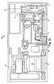
- FIG. 1Ais a schematic diagram of the heat to electricity system of the present invention
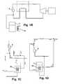
- FIGS. 1B-1Dillustrate various conduit arrangements and working fluid flow directions in the working fluid circuit.
- FIG. 2is a pressure-enthalpy diagram for carbon dioxide
- FIGS. 3A-3Mare schematic drawings of a representative embodiment of a heat engine device and heat engine skid of the present disclosure and related inventions;
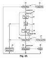
- FIG. 4Ais a flow chart of operational states of a heat engine of the disclosure.
- FIG. 4Bis a flow chart representing a representative start-up and operation sequence for a heat engine of the disclosure.
- FIG. 4Cis a flow chart representing a shut-down sequence for a heat engine of the disclosure.
- the inventive heat engine 100(also referred to herein in the alternative as a “thermal engine”, “power generation device”, “waste heat recovery system” and “heat recovery system”, “heat to electricity system”) of the present disclosure utilizes a thermodynamic cycle which has elements of the Rankine thermodynamic cycle in combination with selected working fluid(s), such as carbon dioxide, to produce power from a wide range of thermal sources.
- thermodynamic cyclewhich has elements of the Rankine thermodynamic cycle in combination with selected working fluid(s), such as carbon dioxide, to produce power from a wide range of thermal sources.
- thermodynamic cycle executed by the heat engine 100is described with reference to a pressure-enthalpy diagram for a selected working fluid, FIG. 2 .
- the thermodynamic cycleis designed to operate as a closed loop thermodynamic cycle in a working fluid circuit having a flow path defined by conduit which interconnects components of the working fluid circuit.
- the thermal engine which operates the cyclemay or may not be hermetically or otherwise entirely sealed (such that no amount of working fluid is leaked from the system into the surrounding environment).
- thermodynamic cyclethat is executed by the thermal engine is shown in its most rudimentary form in FIG. 2 which is a pressure-enthalpy diagram for carbon dioxide.
- the thermodynamic cyclemay be described for ease of understanding by referencing a working fluid at point A on this diagram.
- the working fluidhas its lowest pressure and lowest enthalpy relative to its state at any other point during the cycle and as shown on the diagram. From there, the working fluid is compressed and/or pumped to a higher pressure (point B on the diagram). From there, thermal energy is introduced to the working fluid which both increases the temperature of the working fluid and increases the enthalpy of the working fluid (point C on the diagram). The working fluid is then expanded through a mechanical process to point (D).
- each processi.e., A-B, B-C, C-D, D-A
- each step of the cyclecould be achieved in a variety of ways and/or that it is possible to achieve a variety of different coordinates on the diagram.
- each point on the diagrammay vary dynamically over time as variables within and external to the system change, i.e., ambient temperature, waste heat temperature, amount of mass in the system.
- the cycleis executed during normal, steady state operation such that the low pressure side of the system (points A and D on FIG. 2 ) is between 400 psia and 1500 psia and the high pressure side of the system is between 2500 psia and 4500 psia (points B and C FIG. 2 ).
- the low pressure side of the systempoints A and D on FIG. 2
- the high pressure side of the systemis between 2500 psia and 4500 psia (points B and C FIG. 2 ).
- the working fluidis carbon dioxide.
- carbon dioxideis not intended to be limited to carbon dioxide of any particular type, purity or grade of carbon dioxide although industrial grade carbon dioxide is the preferred working fluid.
- Carbon dioxideis a greenhouse friendly and neutral working fluid that offers benefits such as non-toxicity, non-flammability, easy availability, low price, and no need of recycling.
- the working fluidis in a supercritical state over certain portions of the system (the “high pressure side”), and in a subcritical state at other portions of the system (the “low pressure side”).
- the entire cyclemay be operated such that the working fluid is in a supercritical or subcritical state during the entire execution of the cycle.
- the working fluidmay a binary, ternary or other working fluid blend.
- the working fluid combinationwould be selected for the unique attributes possessed by the fluid combination within a heat recovery system as described herein.
- one such fluid combinationis comprised of a liquid absorbent and carbon dioxide enabling the combined fluid to be pumped in a liquid state to high pressure with less energy input than required to compress CO 2 .
- the working fluidmay be a combination of carbon dioxide and one or more other miscible fluids.
- the working fluidmay be a combination of carbon dioxide and propane, or carbon dioxide and ammonia.
- working fluidis not intended to limit the state or phase of matter that the working fluid is in.
- the working fluidmay be in a fluid phase, a gas phase, a supercritical phase, a subcritical state or any other phase or state at any one or more points within the cycle.
- the inventive heat to electricity systemmay utilize other fluids in other parts of the system, such as water, thermal oils or suitable refrigerants; these other fluids may be used within heat exchangers and equipment external to the heat engine 100 (such as at the Cooler 12 and/or Waste Heat Exchanger 5 shown in FIG. 1A ) and within cooling or other cycles and subsystems that operate within the heat to electricity system (for example at the Radiator 4 cooling loop provided at the alternator 2 of the thermal engine shown in FIG. 1A ).
- these other fluidsmay be used within heat exchangers and equipment external to the heat engine 100 (such as at the Cooler 12 and/or Waste Heat Exchanger 5 shown in FIG. 1A ) and within cooling or other cycles and subsystems that operate within the heat to electricity system (for example at the Radiator 4 cooling loop provided at the alternator 2 of the thermal engine shown in FIG. 1A ).
- a 250 kW (net) or greater skid-based systemis provided for deployment at any source or site of waste or by-product heat.
- Nominal rated output(electrical or work) is not intended to be a limiting feature of the disclosure or related inventions.
- the heat engine 100 of the disclosurehas three primary classes of equipment through which the working fluid may be circulated as the thermodynamic cycle is executed, (i) one or more heat exchangers (ii) one or more pumps and/or compressors and (iii) one or more expansion (work) devices (such as a turbine, a ramjet, or a positive displacement expander 3 such as a geroler or gerotor).
- heat exchangersii) one or more pumps and/or compressors
- expansion (work) devicessuch as a turbine, a ramjet, or a positive displacement expander 3 such as a geroler or gerotor.
- expansion (work) devicessuch as a turbine, a ramjet, or a positive displacement expander 3 such as a geroler or gerotor.
- Each of these pieces of equipmentis operatively coupled in the cycle as shown on FIG. 1A through the use of suitable conduits, couplings and fittings, for example in a working fluid circuit, as further described.
- the heat engine 100may also include a means for converting mechanical energy from the one or more expansion devices into electricity; such means may include but are not limited to a generator, alternator 2 , or other device(s) and related power conditioning or conversion equipment or devices.
- certain components of the heat engine 100may share common elements such as in the case of a turboalternator (shown on FIG. 1A ) (where an expansion device shares a common shaft with an alternator 2 ) or in the case of a turbopump, where an expansion device shares a common shaft with a pump.
- the expansion devicemay be mechanically coupled to the electrical generating means (i) by magnetically coupling the turbine shaft to the rotor of the electrical generating means and/or (ii) by a gearbox operatively coupling the turbine shaft and the rotor of the electrical generating means.
- the heat engine 100may also include other equipment and instruments such as sensors, valves (which may be on/off or variable), fittings, filters, motors, vents, pressure relief equipment, strainers, suitable conduit, and other equipment and sensors.
- the preferred heat engine 100includes the additional equipment shown on FIG. 1A .
- the preferred heat engine 100also includes a system for managing the amount of working fluid within the system such as the mass management system disclosed on FIG. 1A , as further described.
- the preferred heat engine 100also includes a control system and related equipment allowing for the automated and/or semi-automated operation of the engine, the remote control of the system and/or the monitoring of system performance.
- the preferred heat engine 100also includes one or more cooling cycle systems to remove heat from and/or provide thermal management to one or more of the expansion device, the electrical producing means and/or the power electronics 1 .
- one or more cooling cycle systemsto remove heat from and/or provide thermal management to one or more of the expansion device, the electrical producing means and/or the power electronics 1 .
- the system of the current inventionis flexible and may utilize many different types of conventional heat exchangers.
- the preferred embodiment of the inventive heat engine system 100utilizes one or more printed circuit heat exchangers (PCHE) or other construction of the heat exchanger, recuperator or cooler components, each of which may contain one or more cores where each core utilizes microchannel technology.
- PCHEprinted circuit heat exchangers
- recuperator or cooler componentseach of which may contain one or more cores where each core utilizes microchannel technology.
- microchannel technologyincludes, but is not limited to, heat exchangers that contain one or more microchannels, mesochannels, and/or minichannels.
- microchannelsAs used herein the terms “microchannels,” “mesochannels,” and/or “minichannels” are utilized interchangeably.
- the microchannels, mesochannels, and/or minichannels of the present inventionare not limited to any one particular size, width and/or length. Any suitable size, width or length can be utilized depending upon a variety of factors.
- any orientation of the microchannels, mesochannels, and/or minichannelscan be utilized in conjunction with the various embodiments of the present invention.
- the expansion devicemay be a valve or it may be a device capable of transforming high temperature and pressure fluid into mechanical energy.
- the expansion devicemay have an axial or radial construction; it may be single or multi-staged. Examples include a geroler, a gerotor, other types of positive displacement devices such as a pressure swing, a turbine, or any other device capable of transforming a pressure or pressure/enthalpy drop in a working fluid into mechanical energy.
- the deviceis a turboalternator wherein the turbine is operatively coupled to the alternator 2 by either (i) sharing a single shaft (the “single shaft design”) or by operatively coupling the turbine shaft to the alternator 2 rotor (or other shaft) by using high powered magnets to cause two shafts to operate as a single shaft.
- the turbineis physically isolated from the alternator 2 in order to minimize windage losses within the alternator 2 .
- the turbine and alternator 2do not share a common housing (or casing).
- the turbine casingis sealed at the common shaft and thereby isolated from the alternator 2 through the use of suitable shaft seals.
- suitable shaft sealsmay be any of the following, labyrinth seal, a double seal, a dynamically pressure balanced seal (sometimes called a floating ring or fluid filled seal), a dry gas seal or any other scaling mechanism.
- no shaft sealsare required because it is possible to entirely encase the turbine within its housing thereby achieving the desired isolation from the alternator 2 .
- turboalternatoruses air-foil bearings; air foil bearings are selected as the preferred design due because they reduce or eliminate secondary systems and eliminate the requirement for lubrication (which is particularly important when working with the preferred working fluid, carbon dioxide).
- air-foil bearingsair foil bearings are selected as the preferred design due because they reduce or eliminate secondary systems and eliminate the requirement for lubrication (which is particularly important when working with the preferred working fluid, carbon dioxide).
- hydrostatic bearings, aerostatic bearings, magnetic bearings and other bearing typesmay be used.
- the heat engine 100also provides for the delivery of a portion of the working fluid into the expander 3 chamber (or housing) for purposes of cooling one or more parts of the expander 3 .
- the selection of the site within the thermal engine from which to obtain this portion of the working fluidis critical because introduction of the portion of the working fluid into the turboalternator must not disturb the pressure balance (and thus stability) of the turboalternator during operation.
- turboalternatorThis is achieved by matching the pressure of the working fluid delivered into the turboalternator for purposes of cooling with the pressure of the working fluid at the inlet of the turbine; in the preferred heat engine 100 , this portion of the working fluid is obtained after the working fluid passes a valve 25 and a filter F 4 . The working fluid is then conditioned to be at the desired temperature and pressure prior to being introduced into the turboalternator housing. This portion of the working fluid exits the turboalternator at the turboalternator outlet.
- a variety of turboalternator designsare capable of working within the inventive system and to achieve different performance characteristics.
- the device for increasing the pressure of the working fluid from point A-B on FIG. 2may be a compressor, pump, a ramjet type device or other equipment capable of increasing the pressure of the selected working fluid.
- the deviceis a pump 9 , as depicted in FIGS. 1A-1D .
- the pump 9may be a positive displacement pump, a centrifugal pump or any other type or construction of pump.
- the pump 9may be coupled to a VFD (variable frequency drive) 11 to control speed which in turn can be used to control the mass flow rate of the working fluid in the system, and as a consequence of this control the high side system pressure.
- VFDvariable frequency drive
- the VFDmay be in communication with a control system, as further described.
- the pump 9may be constructed such that there is a common shaft (not shown) connecting it with an expansion device enabling the pump to be driven by the mechanical energy generated by expansion of the working fluid (e.g., a turbopump).
- a turbopumpmay be employed in place of or to supplement the pump of the preferred embodiment.
- the “common shaft”may be achieved by using a magnetic coupling between the expansion device's shaft and the pump shaft.
- a secondary expansion device(not shown) coupled to the pump by a common shaft.
- the secondary expansion deviceis located within a stream of fluid which runs parallel to the stream to the primary system expander 3 and there are two valves on either side of the secondary expander to regulate flow to the second expander. It should be noted that there need not be a second expander in order to form a turbopump.
- the common shaft of the turbopumpmay be shared with the common shaft of the primary system expander 3 and/or, in a preferred embodiment, the common shaft of the turboalternator. Similarly, if the system uses a secondary expansion device to share a common shaft with the turbopump, the secondary expansion device need not be located as described above.
- the electrical producing means of one embodiment of the thermal engineis a high speed alternator 2 that is operatively coupled to the turbine to form a turboalternator (as described above).
- the electrical producing meansmay alternatively be any known means of converting mechanical energy into electricity including a generator or alternator 2 . It may be operatively coupled to the primary system expander 3 by a gear box, by sharing a common shaft, or by any other mechanical connection.
- the electrical producing meansis operatively connected to power electronics 1 equipment set.
- the electrical output of the alternator 2is mated with a high efficiency power electronics 1 equipment set that has equipment to provide active load adjustment capability (0-100%).
- the power electronics 1 systemhas equipment to provide the capability to convert high frequency, high voltage power to grid-tie quality power at appropriate conditions with low total harmonic distortion (THD), SAG support, current and voltage following, VAR compensation, for providing torque to start the turboalternator, and dynamic braking capability for versatile and safe control of the turboalternator in the event of load loss; it has also capability of synchronizing and exporting power to the grid for a wide voltage and speed range of the alternator 2 .
- the pump 9 inlet pressurehas a direct influence on the overall system efficiency and the amount of power that can be generated. Because of the thermo-physical properties of the preferred working fluid, carbon dioxide, as the pump 9 inlet temperature rises and falls the system must control the inlet pressure over wide ranges of inlet pressure and temperature (for example, from ⁇ 4 deg F. to 104 deg F.; and 479 psia to 1334 psia). In addition, if the inlet pressure is not carefully controlled, pump 9 cavitation is possible.
- a mass management systemis provided to control the inlet pressure at the pump 9 by adding and removing mass from the system, and this in turn makes the system more efficient.
- the mass management systemoperates with the system semi-passively.
- the systemuses sensors to monitor pressures and temperatures within the high pressure side (from pump 9 outlet to expander 3 inlet) and low pressure side (from expander 3 outlet to pump 9 inlet) of the system.
- the mass management systemmay also include valves, tank heaters or other equipment to facilitate the movement of the working fluid into and out of the system and a mass control tank 7 for storage of working fluid.
- the mass management systemincludes the equipment operatively connected by the bolded lines or conduits of the diagram and at (and including) equipment at the termination points of the mass control system (e.g., 14 , 15 , 16 , 17 , 18 , 21 , 22 , and 23 ).
- the preferred mass management systemremoves higher pressure, denser working fluid (relative to the pressure, temperature, and density on the low pressure side of the system) from the thermodynamic cycle being executed by the thermal engine via valve 16 .
- the mass management systemdispenses working fluid into the main heat engine system 100 via valves 14 and 15 . By controlling the operation of the valves 14 , 15 and 16 , the mass management system adds or removes mass from the system without a pump, reducing system cost, complexity and maintenance.
- the Mass Control Tank 7is filled with working fluid. It is in fluid communication with valves 14 and 16 such that opening either or both valves 14 , 16 will deliver working fluid to the top of the Mass Control Tank 7 .
- the Mass Control Tank 7is in fluid communication with valve 15 such that opening valve 15 will remove working fluid from the bottom of the Mass Control Tank 7 .
- the working fluid contained within the Mass Control Tank 7will stratify with the higher density working fluid at the bottom of the tank and the lower density working fluid at the top of the tank.
- the working fluidmay be in liquid phase, vapor phase or both; if the working fluid is in both vapor phase and liquid phase, there will be a phase boundary separating one phase of working fluid from the other with the denser working fluid at the bottom of the Mass Control Tank 7 . In this way, valve 15 will also deliver to the system the densest working fluid within the Mass Control Tank 7 .
- this equipment setis combined with a set of sensors within the main heat engine system 100 and a control system as described within.
- this mass management systemalso includes equipment used in a variety of operating conditions such as start up, charging, shut-down and venting the heat engine system 100 as shown on FIG. 1A .
- Exemplary operation of the preferred embodiment of the mass management systemfollows.
- the pressure in the mass control tank 7must be increased, to allow for the addition of mass into the system. This can be controlled by opening the valve 14 and thereby allowing higher pressure, higher temperature, lower density supercritical working fluid to flow into the mass control tank 7 .
- Valve 15is opened to allow higher density liquid working fluid at the bottom of the mass control tank 7 to flow into the system and increase pump 9 suction pressure.
- the working fluidmay be in liquid phase, vapor phase or both. If the working fluid is in both vapor phase and liquid phase, there will be a phase boundary in the mass control tank 7 .
- the mass control tank 7will contain either a mixture of liquid and vapor phase working fluid, or a mass of supercritical fluid. In the former case, there will be a phase boundary. In the latter case, there will not be a phase boundary (because one does not exist for supercritical fluids). The fluid will still tend to stratify however, and the valve 15 can be opened to allow higher density liquid working fluid at the bottom of the mass control tank 7 to flow into the system and increase pump suction pressure.
- Working fluid massmay be added to or removed from the working fluid circuit via the mass control tank 7 .
- the mass management system of the disclosuremay be coupled to a control system such that the control of the various valves and other equipment is automated or semi-automated and reacts to system performance data obtained via sensors located throughout the system, and to ambient and environmental conditions.
- FIGS. 1B-1Dother configurations for controlling pressure and/or temperature (or both) in the mass control tank 7 in order to move mass in and out of the system (i.e., the working fluid circuit), include the use of a heater and/or a coil 32 within the vessel/tank 7 or any other means to add or remove heat from the fluid/vapor within the mass control tank 7 .
- mechanical meanssuch as providing pump may be used to get working fluid from the mass control tank 7 into the system.
- One method of controlling the pressure of the working fluid in the low side of the working fluid circuitis by control of the temperature of the working fluid vessel or mass control tank 7 .
- a basic requirementis to maintain the pump 9 inlet pressure above the boiling pressure at the pump 9 inlet. This is accomplished by maintaining the temperature of the mass control tank 7 at a higher level than the pump 9 inlet temperature.
- Exemplary methods of temperature control of the mass control tank 7are: direct electric heat; a heat exchanger coil 32 with pump 9 discharge fluid (which is at a higher temperature than at the pump 9 inlet), or a heat exchanger coil 32 with spent cooling water from the cooler/condenser (also at a temperature higher than at the pump 9 inlet).
- the waste heat recovery system of the disclosuremay be constructed in one form with the primary components described and some or all of which may be arranged on a single skid or platform or in a containment or protective enclosure, collectively referred to herein as a “skid” or “support structure”.
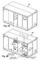
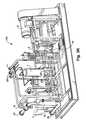
- FIGS. 3A-3Millustrate a representative embodiment of the inventive heat engine 100 with exemplary dimensions, port locations, and access panels.
- the advantages of the skid type packaging of the inventive heat engine 100include general portability and installation access at waste heat sources, protection of components by the external housing, access for repair and maintenance, and ease of connection to the inventive heat engine 100 energy output, to a grid, or to any other sink or consumer of energy produced by the inventive heat engine 100 .
- the heat engine 100is constructed upon a frame having the representative and exemplary dimensions, and within a housing on the frame. Access and connection points are provided external to the housing as indicated, in order to facilitate installation, operation and maintenance.
- FIG. 3B-3Eindicate the various operative connections to the inventive heat engine 100 including the waste heat source supply 19 , cooling water supply 27 , and waste heat source and cooling water return lines 20 , 28 , respectively ( FIG. 3B ); instrument air supply 29 and a mass management (working fluid) fill point 21 ( FIG. 3C ); expander 3 air outlet 30 and pressure relief valves exhaust 22 ( FIG. 3D ); and CO 2 pump vent 30 , high pressure side vent 23 , and additional pressure relief valve exhaust ( FIG. 3E ). Adequate ventilation, cooling via radiators 4 as required and sound-proofing is also accommodated by the housing design.
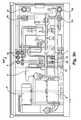
- the principle components of the systemare indicated on FIG. 3M and illustrated pipe connections.
- the variable frequency drive (VFD) 11 , programmable logic controller (PLC) and electrical power panel (Power Out)are schematically illustrated as installed within the housing.
- waste heat exchanger 5Also included on or off the skid, or otherwise in fluid or thermal communication with the working fluid circuit of the system, is at least one waste heat exchanger (WHE) 5 (also shown in FIG. 1 ).
- the WHEuses a heat transfer fluid (such as may be provided by any suitable working fluid or gas, such as for example Therminol XP), which is ported to the WHE 5 from an off-skid thermal source, through the exterior of the skid enclosure through a waste heat source supply port 19 , through the WHE 5 circuit to a waste heat source return 20 exiting the housing ( FIGS. 3A-3E ).
- heatis transferred to the system working fluid in the waste heat exchanger 5 .
- the working fluid flow and pressure entering the expander EXP 3may be controlled by the start, shutoff and bypass valves and by the control system provided herein. Also provided is a cooler 12 , where additional residual heat within the working fluid is extracted from the system, increasing the density of the working fluid, and exits the cooler 12 and into the System Pump 9 .
- the cooler 12may be located on or off the skid.
- Supercritical working fluidexits the pump 9 and flows to the recuperator (REC) 6 , where it is preheated by residual heat from the low pressure working fluid.
- the working fluidthen travels to the waste heat exchanger (WHE) 5 .
- WHE 5waste heat exchanger
- EXP 3expander
- the working fluidOn the downstream side of the EXP 3 , the working fluid is contained in a low pressure side of the cycle. From the EXP 3 the working fluid travels through the REC 6 , then to the cooler 12 and then back to the Pump 9 .
- Suitable pressure and temperature monitoring at points along the lines and at the componentsis provided and may be integrated with an automated control system.
- a control systemcan be provided in operative connection with the inventive heat engine system 100 to monitor and control the described operating parameters, including but not limited to: temperatures, pressures (including port, line and device internal pressures), flow metering and rates, port control, pump operation via the VFD, fluid levels, fluid density leak detection, valve status, filter status, vent status, energy conversion efficiency, energy output, instrumentation, monitoring and adjustment of operating parameters, alarms and shut-offs.
- a representative control systemmay include a suitably configured programmable logic controller (PLC) with inputs from the described devices, components and sensors and output for control of the operating parameters.
- PLCprogrammable logic controller
- the control systemmay be integral with and mounted directly to the inventive heat engine 100 or remote, or as part of distributed control system and integrated with other control systems such as for an electrical supply grid.
- the control systemis programmable to set, control or change any of the various operating parameters depending upon the desired performance of the system.
- Operating instrumentation displaymay be provided as a composite dashboard screen display of the control system, presenting textual and graphic data, and a virtual display of the inventive heat engine 100 and overall and specific status.
- the control systemmay further include capture and storage of heat engine 100 operational history and ranges of all parameters, with query function and report generation.
- a control system and control logic for a 250 kW nominally net power rated Thermafficient Heat Engine 100 of the disclosuremay include the following features, functions and operation: automated unmanned operation under a dedicated control system; local and remote human machine interface capability for data access, data acquisition, unit health monitoring and operation; controlled start-up, operation and shut down in the case of a loss of electrical incoming supply power or power export connection; fully automated start/stop, alarm, shut down, process adjustment, ambient temperature adjustment, data acquisition and synchronization; a controls/power management system designed for interfacing with an external distributed plant control system.
- An exemplary control system for the thermafficient heat engine 100may have multiple control states as depicted in FIG. 4A , including the following steps and functions.
- Initial fill of a working fluid at 41to purge and fill an empty system allowing system to warm for startup.
- Top-up fill at 47to add mass to the mass management tank(s) while the system is in operation.
- Standby at 40for power up of sensors and controller; no fluid circulation; and warm-up systems active if necessary.
- Startup at 42Recirculation idle at 43 with fluid circulation with turbine in bypass mode; gradually warming up recuperator, cooling down waste heat exchanger; BPVWHX initially open, but closes as hot slug is expelled from waste heat exchanger.
- Minimum idle at 44with turbine at minimum speed (.about.20 k RPM) to achieve bearing lift-off; Turbine speed maintained (closed-loop) through a combination of pump speed and valve 24 position. Full speed idle at 45 , with turbine at design speed (40 k RPM) with no load; Pump speed sets turbine speed (closed- loop). Operation at 46 , with turbine operating at design speed and produced nominal design power; switch to load control from pump speed control by ramping up pump speed while using power electronics 1 load to maintain turbine speed at 40 k RPM.
- Shutdown at 48with controlled stop of the turboexpander 3 and gradual cooling of the system.
- An emergency shutdown at 49for unexpected system shutdown; the pump 9 and turboexpander 3 brought down quickly and heat exchangers allowed to cool passively, and venting at 50 to drain the system and remove pressure for maintenance activities.
- control systemmay include an check trips and alarms 51 , with control links to shutdown 48 and emergency shutdown 49 , startup 42 , and continued operation with a recoverable alarm state.
Landscapes
- Engineering & Computer Science (AREA)
- Chemical & Material Sciences (AREA)
- Combustion & Propulsion (AREA)
- Mechanical Engineering (AREA)
- General Engineering & Computer Science (AREA)
- Chemical Kinetics & Catalysis (AREA)
- Engine Equipment That Uses Special Cycles (AREA)
Abstract
Description
Claims (53)
Priority Applications (8)
| Application Number | Priority Date | Filing Date | Title |
|---|---|---|---|
| US12/631,400US8794002B2 (en) | 2009-09-17 | 2009-12-04 | Thermal energy conversion method |
| EP10817804.7AEP2478201B1 (en) | 2009-09-17 | 2010-09-16 | Heat engine and method |
| CN201080050795.7ACN102741536B (en) | 2009-09-17 | 2010-09-16 | Heat engine and heat and power system and method |
| CA2890527ACA2890527C (en) | 2009-09-17 | 2010-09-16 | Heat engine and heat to electricity systems and methods |
| CA2774632ACA2774632C (en) | 2009-09-17 | 2010-09-16 | Heat engine and heat to electricity systems and methods |
| PCT/US2010/049042WO2011034984A1 (en) | 2009-09-17 | 2010-09-16 | Heat engine and heat to electricity systems and methods |
| BR112012006158ABR112012006158B8 (en) | 2009-09-17 | 2010-09-16 | Operating heat engine system for performing a thermodynamic cycle and method for converting thermal energy into mechanical energy by the use of a working fluid |
| US14/450,410US9816403B2 (en) | 2009-09-17 | 2014-08-04 | Thermal energy conversion method |
Applications Claiming Priority (2)
| Application Number | Priority Date | Filing Date | Title |
|---|---|---|---|
| US24320009P | 2009-09-17 | 2009-09-17 | |
| US12/631,400US8794002B2 (en) | 2009-09-17 | 2009-12-04 | Thermal energy conversion method |
Related Child Applications (1)
| Application Number | Title | Priority Date | Filing Date |
|---|---|---|---|
| US14/450,410ContinuationUS9816403B2 (en) | 2009-09-17 | 2014-08-04 | Thermal energy conversion method |
Publications (2)
| Publication Number | Publication Date |
|---|---|
| US20110061387A1 US20110061387A1 (en) | 2011-03-17 |
| US8794002B2true US8794002B2 (en) | 2014-08-05 |
Family
ID=42264905
Family Applications (6)
| Application Number | Title | Priority Date | Filing Date |
|---|---|---|---|
| US12/631,400Active2033-06-04US8794002B2 (en) | 2009-09-17 | 2009-12-04 | Thermal energy conversion method |
| US12/631,379Active2030-08-30US8096128B2 (en) | 2009-09-17 | 2009-12-04 | Heat engine and heat to electricity systems and methods |
| US12/631,412Active2030-12-11US9115605B2 (en) | 2009-09-17 | 2009-12-04 | Thermal energy conversion device |
| US12/880,428Active2030-02-16US8281593B2 (en) | 2009-09-17 | 2010-09-13 | Heat engine and heat to electricity systems and methods with working fluid fill system |
| US13/633,966Active2030-04-28US8966901B2 (en) | 2009-09-17 | 2012-10-03 | Heat engine and heat to electricity systems and methods for working fluid fill system |
| US14/450,410Active2031-06-05US9816403B2 (en) | 2009-09-17 | 2014-08-04 | Thermal energy conversion method |
Family Applications After (5)
| Application Number | Title | Priority Date | Filing Date |
|---|---|---|---|
| US12/631,379Active2030-08-30US8096128B2 (en) | 2009-09-17 | 2009-12-04 | Heat engine and heat to electricity systems and methods |
| US12/631,412Active2030-12-11US9115605B2 (en) | 2009-09-17 | 2009-12-04 | Thermal energy conversion device |
| US12/880,428Active2030-02-16US8281593B2 (en) | 2009-09-17 | 2010-09-13 | Heat engine and heat to electricity systems and methods with working fluid fill system |
| US13/633,966Active2030-04-28US8966901B2 (en) | 2009-09-17 | 2012-10-03 | Heat engine and heat to electricity systems and methods for working fluid fill system |
| US14/450,410Active2031-06-05US9816403B2 (en) | 2009-09-17 | 2014-08-04 | Thermal energy conversion method |
Country Status (6)
| Country | Link |
|---|---|
| US (6) | US8794002B2 (en) |
| EP (1) | EP2478201B1 (en) |
| CN (1) | CN102741536B (en) |
| BR (1) | BR112012006158B8 (en) |
| CA (2) | CA2774632C (en) |
| WO (1) | WO2011034984A1 (en) |
Cited By (15)
| Publication number | Priority date | Publication date | Assignee | Title |
|---|---|---|---|---|
| US20130112761A1 (en)* | 2010-07-15 | 2013-05-09 | Siemens Healthcare Diagnostics Inc. | Methods, Systems, And Apparatus Providing Temperature-Controlled Process Fluid |
| US20150000281A1 (en)* | 2009-09-17 | 2015-01-01 | Echogen Power Systems, Llc | Automated mass management control |
| US20150033737A1 (en)* | 2011-12-02 | 2015-02-05 | Mikhael Mitri | Device and method for utilizing the waste heat of an internal combustion engine, in particular for utilizing the waste heat of a vehicle engine |
| US9359919B1 (en)* | 2015-03-23 | 2016-06-07 | James E. Berry | Recuperated Rankine boost cycle |
| US9742196B1 (en)* | 2016-02-24 | 2017-08-22 | Doosan Fuel Cell America, Inc. | Fuel cell power plant cooling network integrated with a thermal hydraulic engine |
| US9982629B2 (en) | 2015-06-19 | 2018-05-29 | Rolls-Royce Corporation | Engine driven by SC02 cycle with independent shafts for combustion cycle elements and propulsion elements |
| US10060300B2 (en) | 2015-07-20 | 2018-08-28 | Rolls-Royce North American Technologies, Inc. | Sectioned gas turbine engine driven by sCO2 cycle |
| US10443544B2 (en) | 2015-06-15 | 2019-10-15 | Rolls-Royce Corporation | Gas turbine engine driven by sCO2 cycle with advanced heat rejection |
| EP3628830A1 (en) | 2018-09-26 | 2020-04-01 | Sudarshan K.C. | Production of mechanical/electrical energy from heat energy with and by the use of buoyancy factor on evaporation or sublimation and condensation |
| US20210143707A1 (en)* | 2018-07-09 | 2021-05-13 | Siemens Energy, Inc. | Supercritical co2 cooled electrical machine |
| US20220010984A1 (en)* | 2007-09-07 | 2022-01-13 | Scot M. Duncan | Cooling recovery system and method |
| US11662106B2 (en) | 2018-02-23 | 2023-05-30 | Scot M. Duncan | High efficiency dehumidification system and method |
| US11708766B2 (en) | 2019-03-06 | 2023-07-25 | Industrom Power LLC | Intercooled cascade cycle waste heat recovery system |
| US11898451B2 (en) | 2019-03-06 | 2024-02-13 | Industrom Power LLC | Compact axial turbine for high density working fluid |
| US12359613B2 (en) | 2023-01-13 | 2025-07-15 | Arbor Energy and Resources Corporation | Integrated carbon sequestration and power generation system and methods of use |
Families Citing this family (109)
| Publication number | Priority date | Publication date | Assignee | Title |
|---|---|---|---|---|
| US8616323B1 (en) | 2009-03-11 | 2013-12-31 | Echogen Power Systems | Hybrid power systems |
| WO2010121255A1 (en) | 2009-04-17 | 2010-10-21 | Echogen Power Systems | System and method for managing thermal issues in gas turbine engines |
| CN102575532B (en) | 2009-06-22 | 2015-03-18 | 艾克竣电力系统股份有限公司 | Systems and methods for temperature regulation of inlet gas |
| US9316404B2 (en) | 2009-08-04 | 2016-04-19 | Echogen Power Systems, Llc | Heat pump with integral solar collector |
| US8627663B2 (en) | 2009-09-02 | 2014-01-14 | Cummins Intellectual Properties, Inc. | Energy recovery system and method using an organic rankine cycle with condenser pressure regulation |
| US8869531B2 (en) | 2009-09-17 | 2014-10-28 | Echogen Power Systems, Llc | Heat engines with cascade cycles |
| US8794002B2 (en) | 2009-09-17 | 2014-08-05 | Echogen Power Systems | Thermal energy conversion method |
| US8613195B2 (en) | 2009-09-17 | 2013-12-24 | Echogen Power Systems, Llc | Heat engine and heat to electricity systems and methods with working fluid mass management control |
| US8459029B2 (en) | 2009-09-28 | 2013-06-11 | General Electric Company | Dual reheat rankine cycle system and method thereof |
| FR2956153B1 (en)* | 2010-02-11 | 2015-07-17 | Inst Francais Du Petrole | DEVICE FOR MONITORING A LOW FREEZING WORK FLUID CIRCULATING IN A CLOSED CIRCUIT OPERATING ACCORDING TO A RANKINE CYCLE AND METHOD USING SUCH A DEVICE |
| US10094219B2 (en) | 2010-03-04 | 2018-10-09 | X Development Llc | Adiabatic salt energy storage |
| US9046006B2 (en)* | 2010-06-21 | 2015-06-02 | Paccar Inc | Dual cycle rankine waste heat recovery cycle |
| CN103180554B (en)* | 2010-08-13 | 2016-01-20 | 康明斯知识产权公司 | Rankine Cycle Condenser Pressure Control Using Transducer Bypass Valve |
| US8857186B2 (en) | 2010-11-29 | 2014-10-14 | Echogen Power Systems, L.L.C. | Heat engine cycles for high ambient conditions |
| US8616001B2 (en) | 2010-11-29 | 2013-12-31 | Echogen Power Systems, Llc | Driven starter pump and start sequence |
| US8783034B2 (en) | 2011-11-07 | 2014-07-22 | Echogen Power Systems, Llc | Hot day cycle |
| US9249018B2 (en)* | 2011-01-23 | 2016-02-02 | Michael Gurin | Hybrid supercritical power cycle having liquid fuel reactor converting biomass and methanol, gas turbine power generator, and superheated CO2 byproduct |
| US8812264B2 (en) | 2011-03-23 | 2014-08-19 | General Electric Company | Use of wattmeter to determine hydraulic fluid parameters |
| US9388817B1 (en) | 2011-03-24 | 2016-07-12 | Sandia Corporation | Preheating of fluid in a supercritical Brayton cycle power generation system at cold startup |
| WO2012162438A2 (en)* | 2011-05-24 | 2012-11-29 | Navitasmax, Inc. | Supercritical fluids, systems and methods for use |
| US9091262B2 (en)* | 2011-05-27 | 2015-07-28 | General Electric Company | Use of wattmeter to obtain diagnostics of hydraulic system during transient-state start-up operation |
| US8813500B2 (en)* | 2011-08-03 | 2014-08-26 | Dresser-Rand Company | Combined heat exchanger expander mounting system |
| CA2843645C (en)* | 2011-08-04 | 2019-07-30 | Stephen L. Cunningham | Plasma arc furnace and applications |
| US9745899B2 (en)* | 2011-08-05 | 2017-08-29 | National Technology & Engineering Solutions Of Sandia, Llc | Enhancing power cycle efficiency for a supercritical Brayton cycle power system using tunable supercritical gas mixtures |
| DE102011109777A1 (en)* | 2011-08-09 | 2013-02-14 | Linde Aktiengesellschaft | Energy production from low-temperature heat |
| WO2013055391A1 (en) | 2011-10-03 | 2013-04-18 | Echogen Power Systems, Llc | Carbon dioxide refrigeration cycle |
| US8783035B2 (en)* | 2011-11-15 | 2014-07-22 | Shell Oil Company | System and process for generation of electrical power |
| JP2013194715A (en)* | 2012-03-22 | 2013-09-30 | Mitsubishi Heavy Ind Ltd | Solar thermal power generation facility and method of starting up the same |
| US9540960B2 (en)* | 2012-03-29 | 2017-01-10 | Lenr Cars Sarl | Low energy nuclear thermoelectric system |
| US10475980B2 (en)* | 2012-03-29 | 2019-11-12 | Lenr Cars Sa | Thermoelectric vehicle system |
| US8742604B2 (en)* | 2012-06-06 | 2014-06-03 | Energy Recovery, Inc. | Systems and methods for combined flow control and electricity generation |
| US9091278B2 (en) | 2012-08-20 | 2015-07-28 | Echogen Power Systems, Llc | Supercritical working fluid circuit with a turbo pump and a start pump in series configuration |
| US9032734B2 (en)* | 2012-09-26 | 2015-05-19 | Supercritical Technologies, Inc. | Modular power infrastructure network, and associated systems and methods |
| WO2014052927A1 (en) | 2012-09-27 | 2014-04-03 | Gigawatt Day Storage Systems, Inc. | Systems and methods for energy storage and retrieval |
| US9118226B2 (en)* | 2012-10-12 | 2015-08-25 | Echogen Power Systems, Llc | Heat engine system with a supercritical working fluid and processes thereof |
| US9341084B2 (en) | 2012-10-12 | 2016-05-17 | Echogen Power Systems, Llc | Supercritical carbon dioxide power cycle for waste heat recovery |
| US9410451B2 (en) | 2012-12-04 | 2016-08-09 | General Electric Company | Gas turbine engine with integrated bottoming cycle system |
| WO2014117068A1 (en)* | 2013-01-28 | 2014-07-31 | Echogen Power Systems, L.L.C. | Methods for reducing wear on components of a heat engine system at startup |
| WO2014117074A1 (en) | 2013-01-28 | 2014-07-31 | Echogen Power Systems, L.L.C. | Process for controlling a power turbine throttle valve during a supercritical carbon dioxide rankine cycle |
| JP2016519731A (en) | 2013-03-04 | 2016-07-07 | エコージェン パワー システムズ エル.エル.シー.Echogen Power Systems, L.L.C. | Heat engine system with high net power supercritical carbon dioxide circuit |
| US20160017758A1 (en)* | 2013-03-12 | 2016-01-21 | Echogen Power Systems, L.L.C. | Management of working fluid during heat engine system shutdown |
| WO2014165144A1 (en)* | 2013-03-13 | 2014-10-09 | Echogen Power Systems, L.L.C. | Control system for a heat engine system utilizing supercritical working fluid |
| US20160040557A1 (en)* | 2013-03-13 | 2016-02-11 | Echogen Power Systems, L.L.C. | Charging pump system for supplying a working fluid to bearings in a supercritical working fluid circuit |
| WO2014165053A1 (en)* | 2013-03-13 | 2014-10-09 | Echogen Power Systems, L.L.C. | Turbine dry gas seal system and shutdown process |
| WO2014146007A1 (en) | 2013-03-15 | 2014-09-18 | Electratherm, Inc. | Apparatus, systems, and methods for low grade waste heat management |
| KR20150017610A (en)* | 2013-08-07 | 2015-02-17 | 삼성테크윈 주식회사 | Compressor system |
| GB2521430A (en) | 2013-12-19 | 2015-06-24 | Ibm | Device and method for converting heat into mechanical energy |
| KR20150073705A (en)* | 2013-12-23 | 2015-07-01 | 현대자동차주식회사 | System of recycling exhaust heat from internal combustion engine |
| KR102297668B1 (en) | 2014-02-26 | 2021-09-06 | 페레그린 터빈 테크놀로지스, 엘엘씨 | Power generation system and method with partially recuperated flow path |
| JP6688742B2 (en) | 2014-05-09 | 2020-04-28 | カニンガム,スティーブン,エル. | Arc furnace smelting system and method |
| CA2966621C (en)* | 2014-11-03 | 2023-03-07 | Echogen Power Systems, L.L.C. | Valve network and method for controlling pressure within a supercritical working fluid circuit in a heat engine system with a turbopump |
| US10570777B2 (en) | 2014-11-03 | 2020-02-25 | Echogen Power Systems, Llc | Active thrust management of a turbopump within a supercritical working fluid circuit in a heat engine system |
| ES2541581B1 (en)* | 2015-05-07 | 2016-04-26 | Máximo PUJOL LATRE | Electric power production system |
| WO2017027480A1 (en)* | 2015-08-13 | 2017-02-16 | Echogen Power Systems, L.L.C. | Heat engine system including an integrated cooling circuit |
| US10458364B2 (en) | 2015-09-23 | 2019-10-29 | Rolls-Royce Corporation | Propulsion system using supercritical CO2 power transfer |
| EP3153690B1 (en) | 2015-10-08 | 2025-06-04 | Rolls-Royce Corporation | All co2 aircraft |
| KR101664895B1 (en)* | 2016-03-23 | 2016-10-11 | 고등기술연구원연구조합 | Power generation system based on Brayton cycle |
| FR3055923B1 (en) | 2016-09-09 | 2022-05-20 | Eric Bernard Dupont | MECHANICAL SYSTEM FOR PRODUCTION OF MECHANICAL ENERGY FROM LIQUID NITROGEN AND CORRESPONDING METHOD |
| EP3555432A4 (en)* | 2016-12-13 | 2020-08-12 | Blue Box Technology Inc. | Apparatus for extracting energy from waste heat |
| JP6771665B2 (en)* | 2016-12-22 | 2020-10-21 | シーメンス アクティエンゲゼルシャフト | Power plant with gas turbine intake system |
| US11053847B2 (en) | 2016-12-28 | 2021-07-06 | Malta Inc. | Baffled thermoclines in thermodynamic cycle systems |
| US10458284B2 (en) | 2016-12-28 | 2019-10-29 | Malta Inc. | Variable pressure inventory control of closed cycle system with a high pressure tank and an intermediate pressure tank |
| US10233833B2 (en) | 2016-12-28 | 2019-03-19 | Malta Inc. | Pump control of closed cycle power generation system |
| US10221775B2 (en) | 2016-12-29 | 2019-03-05 | Malta Inc. | Use of external air for closed cycle inventory control |
| US10436109B2 (en) | 2016-12-31 | 2019-10-08 | Malta Inc. | Modular thermal storage |
| KR101882137B1 (en) | 2017-03-20 | 2018-07-25 | 두산중공업 주식회사 | Device for supplying of sealing gas |
| KR101868271B1 (en) | 2017-03-20 | 2018-06-15 | 두산중공업 주식회사 | Device and method for suppling of working fuid |
| KR101868273B1 (en) | 2017-03-28 | 2018-06-15 | 두산중공업 주식회사 | Control device for suppling of working fluid |
| GB2563818A (en)* | 2017-05-05 | 2019-01-02 | Ceox Ltd | Mechanical/electrical power generation system |
| WO2018213080A1 (en)* | 2017-05-17 | 2018-11-22 | Cummins Inc. | Waste heat recovery systems with heat exchangers |
| EP3631173B1 (en)* | 2017-05-26 | 2024-08-28 | Echogen Power Systems (Delaware), Inc. | System and method for controlling the pressure of a working fluid at an inlet of a pressurization device of a heat engine system |
| KR102021900B1 (en) | 2017-12-13 | 2019-09-17 | 두산중공업 주식회사 | Supercritical CO2 generating system and method for operating thereof |
| KR102012480B1 (en)* | 2017-12-19 | 2019-08-20 | 한국에너지기술연구원 | Closed supercritical carbon dioxide power cycle system and method of the same |
| GB2571263B (en)* | 2018-02-16 | 2020-05-27 | Jaguar Land Rover Ltd | Apparatus and method for low grade heat recovery in an electric vehicle |
| US10883388B2 (en) | 2018-06-27 | 2021-01-05 | Echogen Power Systems Llc | Systems and methods for generating electricity via a pumped thermal energy storage system |
| US11708805B2 (en) | 2018-12-10 | 2023-07-25 | King Abdullah University Of Science And Technology | Engine and power cycles fueled by performic acid or formic acid |
| US11598284B2 (en)* | 2018-12-20 | 2023-03-07 | Swedish Stirling Ab | Recovery of energy in residue gases |
| CN109667633B (en)* | 2019-01-07 | 2024-03-19 | 苏州欧拉透平机械有限公司 | Energy output system and method applied to urea device |
| KR102172229B1 (en)* | 2019-01-17 | 2020-10-30 | 한국전력공사 | High efficiency carbon dioxide power system and its start-up method |
| US11814961B2 (en)* | 2019-05-17 | 2023-11-14 | ThermalTech Holdings, LLC | Shifting head assisted rotary positive displacement device |
| CN110273723A (en)* | 2019-06-13 | 2019-09-24 | 天津大学 | A kind of shunt carbon dioxide power circulation system for afterheat of IC engine recycling |
| US11598327B2 (en)* | 2019-11-05 | 2023-03-07 | General Electric Company | Compressor system with heat recovery |
| CN116575992A (en) | 2019-11-16 | 2023-08-11 | 马耳他股份有限公司 | Dual power system pumping thermoelectric storage state conversion |
| US11035260B1 (en) | 2020-03-31 | 2021-06-15 | Veritask Energy Systems, Inc. | System, apparatus, and method for energy conversion |
| US11435120B2 (en) | 2020-05-05 | 2022-09-06 | Echogen Power Systems (Delaware), Inc. | Split expansion heat pump cycle |
| US11286804B2 (en) | 2020-08-12 | 2022-03-29 | Malta Inc. | Pumped heat energy storage system with charge cycle thermal integration |
| US11486305B2 (en) | 2020-08-12 | 2022-11-01 | Malta Inc. | Pumped heat energy storage system with load following |
| CA3189001A1 (en) | 2020-08-12 | 2022-02-17 | Mert Geveci | Pumped heat energy storage system with modular turbomachinery |
| US11396826B2 (en) | 2020-08-12 | 2022-07-26 | Malta Inc. | Pumped heat energy storage system with electric heating integration |
| US11480067B2 (en) | 2020-08-12 | 2022-10-25 | Malta Inc. | Pumped heat energy storage system with generation cycle thermal integration |
| EP4193036A1 (en) | 2020-08-12 | 2023-06-14 | Malta Inc. | Pumped heat energy storage system with steam cycle |
| US11454167B1 (en) | 2020-08-12 | 2022-09-27 | Malta Inc. | Pumped heat energy storage system with hot-side thermal integration |
| CA3201373A1 (en) | 2020-12-09 | 2022-06-16 | Timothy Held | Three reservoir electric thermal energy storage system |
| US11421663B1 (en) | 2021-04-02 | 2022-08-23 | Ice Thermal Harvesting, Llc | Systems and methods for generation of electrical power in an organic Rankine cycle operation |
| US11326550B1 (en) | 2021-04-02 | 2022-05-10 | Ice Thermal Harvesting, Llc | Systems and methods utilizing gas temperature as a power source |
| US11592009B2 (en) | 2021-04-02 | 2023-02-28 | Ice Thermal Harvesting, Llc | Systems and methods for generation of electrical power at a drilling rig |
| US11236735B1 (en) | 2021-04-02 | 2022-02-01 | Ice Thermal Harvesting, Llc | Methods for generating geothermal power in an organic Rankine cycle operation during hydrocarbon production based on wellhead fluid temperature |
| US11493029B2 (en) | 2021-04-02 | 2022-11-08 | Ice Thermal Harvesting, Llc | Systems and methods for generation of electrical power at a drilling rig |
| US12312981B2 (en) | 2021-04-02 | 2025-05-27 | Ice Thermal Harvesting, Llc | Systems and methods utilizing gas temperature as a power source |
| US11480074B1 (en) | 2021-04-02 | 2022-10-25 | Ice Thermal Harvesting, Llc | Systems and methods utilizing gas temperature as a power source |
| US11293414B1 (en) | 2021-04-02 | 2022-04-05 | Ice Thermal Harvesting, Llc | Systems and methods for generation of electrical power in an organic rankine cycle operation |
| US11486370B2 (en) | 2021-04-02 | 2022-11-01 | Ice Thermal Harvesting, Llc | Modular mobile heat generation unit for generation of geothermal power in organic Rankine cycle operations |
| US11644015B2 (en) | 2021-04-02 | 2023-05-09 | Ice Thermal Harvesting, Llc | Systems and methods for generation of electrical power at a drilling rig |
| CN113280672B (en)* | 2021-06-18 | 2022-03-04 | 电子科技大学 | Multistage low temperature waste heat recovery system based on supercritical carbon dioxide |
| DE102021003419B3 (en)* | 2021-07-02 | 2022-08-11 | Egon Streit | Systematic CO2 gas engine |
| EP4430285A1 (en) | 2021-12-14 | 2024-09-18 | Malta Inc. | Pumped heat energy storage system integrated with coal-fired energy generation unit |
| US12180861B1 (en) | 2022-12-30 | 2024-12-31 | Ice Thermal Harvesting, Llc | Systems and methods to utilize heat carriers in conversion of thermal energy |
| WO2025010090A1 (en) | 2023-02-07 | 2025-01-09 | Supercritical Storage Company, Inc. | Waste heat integration into pumped thermal energy storage |
| DE102023202959A1 (en)* | 2023-03-30 | 2024-10-02 | Deutsches Zentrum für Luft- und Raumfahrt e.V. | Power adjustment device and method for power adjustment for a thermodynamic machine operating according to the closed Brayton cycle |
Citations (357)
| Publication number | Priority date | Publication date | Assignee | Title |
|---|---|---|---|---|
| US2575478A (en) | 1948-06-26 | 1951-11-20 | Leon T Wilson | Method and system for utilizing solar energy |
| US2634375A (en) | 1949-11-07 | 1953-04-07 | Guimbal Jean Claude | Combined turbine and generator unit |
| US2691280A (en) | 1952-08-04 | 1954-10-12 | James A Albert | Refrigeration system and drying means therefor |
| GB856985A (en) | 1957-12-16 | 1960-12-21 | Licencia Talalmanyokat | Process and device for controlling an equipment for cooling electrical generators |
| US3095274A (en) | 1958-07-01 | 1963-06-25 | Air Prod & Chem | Hydrogen liquefaction and conversion systems |
| US3105748A (en) | 1957-12-09 | 1963-10-01 | Parkersburg Rig & Reel Co | Method and system for drying gas and reconcentrating the drying absorbent |
| US3237403A (en) | 1963-03-19 | 1966-03-01 | Douglas Aircraft Co Inc | Supercritical cycle heat engine |
| US3277955A (en) | 1961-11-01 | 1966-10-11 | Heller Laszlo | Control apparatus for air-cooled steam condensation systems |
| US3401277A (en) | 1962-12-31 | 1968-09-10 | United Aircraft Corp | Two-phase fluid power generator with no moving parts |
| US3622767A (en) | 1967-01-16 | 1971-11-23 | Ibm | Adaptive control system and method |
| US3736745A (en) | 1971-06-09 | 1973-06-05 | H Karig | Supercritical thermal power system using combustion gases for working fluid |
| US3772879A (en) | 1971-08-04 | 1973-11-20 | Energy Res Corp | Heat engine |
| US3791137A (en) | 1972-05-15 | 1974-02-12 | Secr Defence | Fluidized bed powerplant with helium circuit, indirect heat exchange and compressed air bypass control |
| US3939328A (en) | 1973-11-06 | 1976-02-17 | Westinghouse Electric Corporation | Control system with adaptive process controllers especially adapted for electric power plant operation |
| US3971211A (en) | 1974-04-02 | 1976-07-27 | Mcdonnell Douglas Corporation | Thermodynamic cycles with supercritical CO2 cycle topping |
| US3982379A (en) | 1974-08-14 | 1976-09-28 | Siempelkamp Giesserei Kg | Steam-type peak-power generating system |
| US3998058A (en)* | 1974-09-16 | 1976-12-21 | Fast Load Control Inc. | Method of effecting fast turbine valving for improvement of power system stability |
| US4009575A (en) | 1975-05-12 | 1977-03-01 | said Thomas L. Hartman, Jr. | Multi-use absorption/regeneration power cycle |
| US4029255A (en) | 1972-04-26 | 1977-06-14 | Westinghouse Electric Corporation | System for operating a steam turbine with bumpless digital megawatt and impulse pressure control loop switching |
| US4030312A (en) | 1976-04-07 | 1977-06-21 | Shantzer-Wallin Corporation | Heat pumps with solar heat source |
| US4049407A (en) | 1976-08-18 | 1977-09-20 | Bottum Edward W | Solar assisted heat pump system |
| US4070870A (en) | 1976-10-04 | 1978-01-31 | Borg-Warner Corporation | Heat pump assisted solar powered absorption system |
| US4099381A (en) | 1977-07-07 | 1978-07-11 | Rappoport Marc D | Geothermal and solar integrated energy transport and conversion system |
| US4119140A (en) | 1975-01-27 | 1978-10-10 | The Marley Cooling Tower Company | Air cooled atmospheric heat exchanger |
| US4152901A (en) | 1975-12-30 | 1979-05-08 | Aktiebolaget Carl Munters | Method and apparatus for transferring energy in an absorption heating and cooling system |
| US4164849A (en) | 1976-09-30 | 1979-08-21 | The United States Of America As Represented By The United States Department Of Energy | Method and apparatus for thermal power generation |
| US4164848A (en) | 1976-12-21 | 1979-08-21 | Paul Viktor Gilli | Method and apparatus for peak-load coverage and stop-gap reserve in steam power plants |
| US4182960A (en) | 1978-05-30 | 1980-01-08 | Reuyl John S | Integrated residential and automotive energy system |
| US4183220A (en) | 1976-10-08 | 1980-01-15 | Shaw John B | Positive displacement gas expansion engine with low temperature differential |
| US4198827A (en)* | 1976-03-15 | 1980-04-22 | Schoeppel Roger J | Power cycles based upon cyclical hydriding and dehydriding of a material |
| US4208882A (en) | 1977-12-15 | 1980-06-24 | General Electric Company | Start-up attemperator |
| US4221185A (en) | 1979-01-22 | 1980-09-09 | Ball Corporation | Apparatus for applying lubricating materials to metallic substrates |
| US4233085A (en) | 1979-03-21 | 1980-11-11 | Photon Power, Inc. | Solar panel module |
| US4248049A (en) | 1979-07-09 | 1981-02-03 | Hybrid Energy Systems, Inc. | Temperature conditioning system suitable for use with a solar energy collection and storage apparatus or a low temperature energy source |
| US4257232A (en) | 1976-11-26 | 1981-03-24 | Bell Ealious D | Calcium carbide power system |
| US4287430A (en) | 1980-01-18 | 1981-09-01 | Foster Wheeler Energy Corporation | Coordinated control system for an electric power plant |
| GB2075608A (en) | 1980-04-28 | 1981-11-18 | Anderson Max Franklin | Methods of and apparatus for generating power |
| US4336692A (en) | 1980-04-16 | 1982-06-29 | Atlantic Richfield Company | Dual source heat pump |
| US4347711A (en) | 1980-07-25 | 1982-09-07 | The Garrett Corporation | Heat-actuated space conditioning unit with bottoming cycle |
| US4347714A (en) | 1980-07-25 | 1982-09-07 | The Garrett Corporation | Heat pump systems for residential use |
| US4372125A (en) | 1980-12-22 | 1983-02-08 | General Electric Company | Turbine bypass desuperheater control system |
| US4384568A (en) | 1980-11-12 | 1983-05-24 | Palmatier Everett P | Solar heating system |
| US4391101A (en) | 1981-04-01 | 1983-07-05 | General Electric Company | Attemperator-deaerator condenser |
| US4420947A (en) | 1981-07-10 | 1983-12-20 | System Homes Company, Ltd. | Heat pump air conditioning system |
| US4428190A (en)* | 1981-08-07 | 1984-01-31 | Ormat Turbines, Ltd. | Power plant utilizing multi-stage turbines |
| US4433554A (en) | 1982-07-16 | 1984-02-28 | Institut Francais Du Petrole | Process for producing cold and/or heat by use of an absorption cycle with carbon dioxide as working fluid |
| US4439687A (en) | 1982-07-09 | 1984-03-27 | Uop Inc. | Generator synchronization in power recovery units |
| US4439994A (en) | 1982-07-06 | 1984-04-03 | Hybrid Energy Systems, Inc. | Three phase absorption systems and methods for refrigeration and heat pump cycles |
| US4448033A (en) | 1982-03-29 | 1984-05-15 | Carrier Corporation | Thermostat self-test apparatus and method |
| US4450363A (en) | 1982-05-07 | 1984-05-22 | The Babcock & Wilcox Company | Coordinated control technique and arrangement for steam power generating system |
| US4455836A (en) | 1981-09-25 | 1984-06-26 | Westinghouse Electric Corp. | Turbine high pressure bypass temperature control system and method |
| US4467621A (en) | 1982-09-22 | 1984-08-28 | Brien Paul R O | Fluid/vacuum chamber to remove heat and heat vapor from a refrigerant fluid |
| US4467609A (en) | 1982-08-27 | 1984-08-28 | Loomis Robert G | Working fluids for electrical generating plants |
| US4475353A (en) | 1982-06-16 | 1984-10-09 | The Puraq Company | Serial absorption refrigeration process |
| US4489562A (en) | 1982-11-08 | 1984-12-25 | Combustion Engineering, Inc. | Method and apparatus for controlling a gasifier |
| US4489563A (en) | 1982-08-06 | 1984-12-25 | Kalina Alexander Ifaevich | Generation of energy |
| US4498289A (en) | 1982-12-27 | 1985-02-12 | Ian Osgerby | Carbon dioxide power cycle |
| US4516403A (en) | 1983-10-21 | 1985-05-14 | Mitsui Engineering & Shipbuilding Co., Ltd. | Waste heat recovery system for an internal combustion engine |
| US4549401A (en) | 1981-09-19 | 1985-10-29 | Saarbergwerke Aktiengesellschaft | Method and apparatus for reducing the initial start-up and subsequent stabilization period losses, for increasing the usable power and for improving the controllability of a thermal power plant |
| US4555905A (en) | 1983-01-26 | 1985-12-03 | Mitsui Engineering & Shipbuilding Co., Ltd. | Method of and system for utilizing thermal energy accumulator |
| US4558228A (en) | 1981-10-13 | 1985-12-10 | Jaakko Larjola | Energy converter |
| US4573321A (en) | 1984-11-06 | 1986-03-04 | Ecoenergy I, Ltd. | Power generating cycle |
| US4578953A (en) | 1984-07-16 | 1986-04-01 | Ormat Systems Inc. | Cascaded power plant using low and medium temperature source fluid |
| US4589255A (en) | 1984-10-25 | 1986-05-20 | Westinghouse Electric Corp. | Adaptive temperature control system for the supply of steam to a steam turbine |
| US4636578A (en) | 1985-04-11 | 1987-01-13 | Atlantic Richfield Company | Photocell assembly |
| US4674297A (en) | 1983-09-29 | 1987-06-23 | Vobach Arnold R | Chemically assisted mechanical refrigeration process |
| US4694189A (en) | 1985-09-25 | 1987-09-15 | Hitachi, Ltd. | Control system for variable speed hydraulic turbine generator apparatus |
| US4700543A (en) | 1984-07-16 | 1987-10-20 | Ormat Turbines (1965) Ltd. | Cascaded power plant using low and medium temperature source fluid |
| US4756162A (en) | 1987-04-09 | 1988-07-12 | Abraham Dayan | Method of utilizing thermal energy |
| US4765143A (en) | 1987-02-04 | 1988-08-23 | Cbi Research Corporation | Power plant using CO2 as a working fluid |
| US4773212A (en) | 1981-04-01 | 1988-09-27 | United Technologies Corporation | Balancing the heat flow between components associated with a gas turbine engine |
| US4798056A (en) | 1980-02-11 | 1989-01-17 | Sigma Research, Inc. | Direct expansion solar collector-heat pump system |
| US4813242A (en) | 1987-11-17 | 1989-03-21 | Wicks Frank E | Efficient heater and air conditioner |
| US4821514A (en) | 1987-06-09 | 1989-04-18 | Deere & Company | Pressure flow compensating control circuit |
| US4986071A (en) | 1989-06-05 | 1991-01-22 | Komatsu Dresser Company | Fast response load sense control system |
| US4993483A (en) | 1990-01-22 | 1991-02-19 | Charles Harris | Geothermal heat transfer system |
| US5000003A (en) | 1989-08-28 | 1991-03-19 | Wicks Frank E | Combined cycle engine |
| WO1991005145A1 (en) | 1989-10-02 | 1991-04-18 | Chicago Bridge & Iron Technical Services Company | Power generation from lng |
| US5050375A (en) | 1985-12-26 | 1991-09-24 | Dipac Associates | Pressurized wet combustion at increased temperature |
| US5098194A (en) | 1990-06-27 | 1992-03-24 | Union Carbide Chemicals & Plastics Technology Corporation | Semi-continuous method and apparatus for forming a heated and pressurized mixture of fluids in a predetermined proportion |
| US5164020A (en) | 1991-05-24 | 1992-11-17 | Solarex Corporation | Solar panel |
| US5176321A (en) | 1991-11-12 | 1993-01-05 | Illinois Tool Works Inc. | Device for applying electrostatically charged lubricant |
| US5203159A (en) | 1990-03-12 | 1993-04-20 | Hitachi Ltd. | Pressurized fluidized bed combustion combined cycle power plant and method of operating the same |
| US5228310A (en) | 1984-05-17 | 1993-07-20 | Vandenberg Leonard B | Solar heat pump |
| JPH05321612A (en) | 1992-05-18 | 1993-12-07 | Tsukishima Kikai Co Ltd | Low pressure power generating method and device therefor |
| US5291960A (en) | 1992-11-30 | 1994-03-08 | Ford Motor Company | Hybrid electric vehicle regenerative braking energy recovery system |
| US5335510A (en) | 1989-11-14 | 1994-08-09 | Rocky Research | Continuous constant pressure process for staging solid-vapor compounds |
| US5360057A (en) | 1991-09-09 | 1994-11-01 | Rocky Research | Dual-temperature heat pump apparatus and system |
| US5392606A (en) | 1994-02-22 | 1995-02-28 | Martin Marietta Energy Systems, Inc. | Self-contained small utility system |
| US5440882A (en) | 1993-11-03 | 1995-08-15 | Exergy, Inc. | Method and apparatus for converting heat from geothermal liquid and geothermal steam to electric power |
| US5444972A (en) | 1994-04-12 | 1995-08-29 | Rockwell International Corporation | Solar-gas combined cycle electrical generating system |
| US5488828A (en) | 1993-05-14 | 1996-02-06 | Brossard; Pierre | Energy generating apparatus |
| US5490386A (en) | 1991-09-06 | 1996-02-13 | Siemens Aktiengesellschaft | Method for cooling a low pressure steam turbine operating in the ventilation mode |
| WO1996009500A1 (en) | 1994-09-22 | 1996-03-28 | Thermal Energy Accumulator Products Pty. Ltd. | A temperature control system for fluids |
| US5503222A (en) | 1989-07-28 | 1996-04-02 | Uop | Carousel heat exchanger for sorption cooling process |
| US5531073A (en) | 1989-07-01 | 1996-07-02 | Ormat Turbines (1965) Ltd | Rankine cycle power plant utilizing organic working fluid |
| US5538564A (en) | 1994-03-18 | 1996-07-23 | Regents Of The University Of California | Three dimensional amorphous silicon/microcrystalline silicon solar cells |
| US5542203A (en) | 1994-08-05 | 1996-08-06 | Addco Manufacturing, Inc. | Mobile sign with solar panel |
| US5570578A (en) | 1992-12-02 | 1996-11-05 | Stein Industrie | Heat recovery method and device suitable for combined cycles |
| US5588298A (en) | 1995-10-20 | 1996-12-31 | Exergy, Inc. | Supplying heat to an externally fired power system |
| US5600967A (en) | 1995-04-24 | 1997-02-11 | Meckler; Milton | Refrigerant enhancer-absorbent concentrator and turbo-charged absorption chiller |
| US5647221A (en) | 1995-10-10 | 1997-07-15 | The George Washington University | Pressure exchanging ejector and refrigeration apparatus and method |
| US5649426A (en) | 1995-04-27 | 1997-07-22 | Exergy, Inc. | Method and apparatus for implementing a thermodynamic cycle |
| JP2641581B2 (en) | 1990-01-19 | 1997-08-13 | 東洋エンジニアリング株式会社 | Power generation method |
| US5676382A (en) | 1995-06-06 | 1997-10-14 | Freudenberg Nok General Partnership | Mechanical face seal assembly including a gasket |
| US5680753A (en) | 1994-08-19 | 1997-10-28 | Asea Brown Boveri Ag | Method of regulating the rotational speed of a gas turbine during load disconnection |
| US5738164A (en) | 1996-11-15 | 1998-04-14 | Geohil Ag | Arrangement for effecting an energy exchange between earth soil and an energy exchanger |
| US5754613A (en) | 1996-02-07 | 1998-05-19 | Kabushiki Kaisha Toshiba | Power plant |
| US5771700A (en) | 1995-11-06 | 1998-06-30 | Ecr Technologies, Inc. | Heat pump apparatus and related methods providing enhanced refrigerant flow control |
| US5789822A (en) | 1996-08-12 | 1998-08-04 | Revak Turbomachinery Services, Inc. | Speed control system for a prime mover |
| US5813215A (en) | 1995-02-21 | 1998-09-29 | Weisser; Arthur M. | Combined cycle waste heat recovery system |
| US5833876A (en) | 1992-06-03 | 1998-11-10 | Henkel Corporation | Polyol ester lubricants for refrigerating compressors operating at high temperatures |
| US5873260A (en) | 1997-04-02 | 1999-02-23 | Linhardt; Hans D. | Refrigeration apparatus and method |
| US5874039A (en) | 1997-09-22 | 1999-02-23 | Borealis Technical Limited | Low work function electrode |
| US5894836A (en) | 1997-04-26 | 1999-04-20 | Industrial Technology Research Institute | Compound solar water heating and dehumidifying device |
| US5899067A (en) | 1996-08-21 | 1999-05-04 | Hageman; Brian C. | Hydraulic engine powered by introduction and removal of heat from a working fluid |
| US5903060A (en) | 1988-07-14 | 1999-05-11 | Norton; Peter | Small heat and electricity generating plant |
| US5918460A (en) | 1997-05-05 | 1999-07-06 | United Technologies Corporation | Liquid oxygen gasifying system for rocket engines |
| US5941238A (en) | 1997-02-25 | 1999-08-24 | Ada Tracy | Heat storage vessels for use with heat pumps and solar panels |
| US5943869A (en) | 1997-01-16 | 1999-08-31 | Praxair Technology, Inc. | Cryogenic cooling of exothermic reactor |
| US5946931A (en) | 1998-02-25 | 1999-09-07 | The United States Of America As Represented By The Administrator Of The National Aeronautics And Space Administration | Evaporative cooling membrane device |
| US5973050A (en) | 1996-07-01 | 1999-10-26 | Integrated Cryoelectronic Inc. | Composite thermoelectric material |
| US6037683A (en) | 1997-11-18 | 2000-03-14 | Abb Patent Gmbh | Gas-cooled turbogenerator |
| US6041604A (en) | 1998-07-14 | 2000-03-28 | Helios Research Corporation | Rankine cycle and working fluid therefor |
| US6058930A (en) | 1999-04-21 | 2000-05-09 | Shingleton; Jefferson | Solar collector and tracker arrangement |
| US6062815A (en) | 1998-06-05 | 2000-05-16 | Freudenberg-Nok General Partnership | Unitized seal impeller thrust system |
| US6065280A (en) | 1998-04-08 | 2000-05-23 | General Electric Co. | Method of heating gas turbine fuel in a combined cycle power plant using multi-component flow mixtures |
| US6066797A (en) | 1997-03-27 | 2000-05-23 | Canon Kabushiki Kaisha | Solar cell module |
| US6070405A (en) | 1995-08-03 | 2000-06-06 | Siemens Aktiengesellschaft | Method for controlling the rotational speed of a turbine during load shedding |
| US6082110A (en) | 1999-06-29 | 2000-07-04 | Rosenblatt; Joel H. | Auto-reheat turbine system |
| US6105368A (en) | 1999-01-13 | 2000-08-22 | Abb Alstom Power Inc. | Blowdown recovery system in a Kalina cycle power generation system |
| US6112547A (en) | 1998-07-10 | 2000-09-05 | Spauschus Associates, Inc. | Reduced pressure carbon dioxide-based refrigeration system |
| US6158237A (en) | 1995-11-10 | 2000-12-12 | The University Of Nottingham | Rotatable heat transfer apparatus |
| US6164655A (en) | 1997-12-23 | 2000-12-26 | Asea Brown Boveri Ag | Method and arrangement for sealing off a separating gap, formed between a rotor and a stator, in a non-contacting manner |
| US6202782B1 (en) | 1999-05-03 | 2001-03-20 | Takefumi Hatanaka | Vehicle driving method and hybrid vehicle propulsion system |
| US6223846B1 (en) | 1998-06-15 | 2001-05-01 | Michael M. Schechter | Vehicle operating method and system |
| US6233938B1 (en) | 1998-07-14 | 2001-05-22 | Helios Energy Technologies, Inc. | Rankine cycle and working fluid therefor |
| WO2001044658A1 (en) | 1999-12-17 | 2001-06-21 | The Ohio State University | Heat engine |
| JP2001193419A (en) | 2000-01-11 | 2001-07-17 | Yutaka Maeda | Combined power generating system and its device |
| US20010015061A1 (en) | 1995-06-07 | 2001-08-23 | Fermin Viteri | Hydrocarbon combustion power generation system with CO2 sequestration |
| US6282917B1 (en) | 1998-07-16 | 2001-09-04 | Stephen Mongan | Heat exchange method and apparatus |
| US6282900B1 (en) | 2000-06-27 | 2001-09-04 | Ealious D. Bell | Calcium carbide power system with waste energy recovery |
| US6295818B1 (en) | 1999-06-29 | 2001-10-02 | Powerlight Corporation | PV-thermal solar power assembly |
| US6299690B1 (en) | 1999-11-18 | 2001-10-09 | National Research Council Of Canada | Die wall lubrication method and apparatus |
| US20010030952A1 (en) | 2000-03-15 | 2001-10-18 | Roy Radhika R. | H.323 back-end services for intra-zone and inter-zone mobility management |
| US6341781B1 (en) | 1998-04-15 | 2002-01-29 | Burgmann Dichtungswerke Gmbh & Co. Kg | Sealing element for a face seal assembly |
| US20020029558A1 (en) | 1998-09-15 | 2002-03-14 | Tamaro Robert F. | System and method for waste heat augmentation in a combined cycle plant through combustor gas diversion |
| JP2002097965A (en) | 2000-09-21 | 2002-04-05 | Mitsui Eng & Shipbuild Co Ltd | Power generation system using cold heat |
| US6374630B1 (en) | 2001-05-09 | 2002-04-23 | The United States Of America As Represented By The Administrator Of The National Aeronautics And Space Administration | Carbon dioxide absorption heat pump |
| DE10052993A1 (en) | 2000-10-18 | 2002-05-02 | Doekowa Ges Zur Entwicklung De | Process for converting thermal energy into mechanical energy in a thermal engine comprises passing a working medium through an expansion phase to expand the medium, and then passing |
| US6393851B1 (en)* | 2000-09-14 | 2002-05-28 | Xdx, Llc | Vapor compression system |
| US20020066270A1 (en) | 2000-11-06 | 2002-06-06 | Capstone Turbine Corporation | Generated system bottoming cycle |
| US20020078696A1 (en) | 2000-12-04 | 2002-06-27 | Amos Korin | Hybrid heat pump |
| US20020078697A1 (en) | 2000-12-22 | 2002-06-27 | Alexander Lifson | Pre-start bearing lubrication system employing an accumulator |
| US20020082747A1 (en) | 2000-08-11 | 2002-06-27 | Kramer Robert A. | Energy management system and methods for the optimization of distributed generation |
| US6432320B1 (en) | 1998-11-02 | 2002-08-13 | Patrick Bonsignore | Refrigerant and heat transfer fluid additive |
| US6434955B1 (en) | 2001-08-07 | 2002-08-20 | The National University Of Singapore | Electro-adsorption chiller: a miniaturized cooling cycle with applications from microelectronics to conventional air-conditioning |
| US6442951B1 (en) | 1998-06-30 | 2002-09-03 | Ebara Corporation | Heat exchanger, heat pump, dehumidifier, and dehumidifying method |
| US6446425B1 (en) | 1998-06-17 | 2002-09-10 | Ramgen Power Systems, Inc. | Ramjet engine for power generation |
| US6446465B1 (en) | 1997-12-11 | 2002-09-10 | Bhp Petroleum Pty, Ltd. | Liquefaction process and apparatus |
| US6463730B1 (en) | 2000-07-12 | 2002-10-15 | Honeywell Power Systems Inc. | Valve control logic for gas turbine recuperator |
| US6484490B1 (en)* | 2000-05-09 | 2002-11-26 | Ingersoll-Rand Energy Systems Corp. | Gas turbine system and method |
| US20030061823A1 (en) | 2001-09-25 | 2003-04-03 | Alden Ray M. | Deep cycle heating and cooling apparatus and process |
| US6571548B1 (en) | 1998-12-31 | 2003-06-03 | Ormat Industries Ltd. | Waste heat recovery in an organic energy converter using an intermediate liquid cycle |
| US6598397B2 (en) | 2001-08-10 | 2003-07-29 | Energetix Micropower Limited | Integrated micro combined heat and power system |
| US20030154718A1 (en) | 1997-04-02 | 2003-08-21 | Electric Power Research Institute | Method and system for a thermodynamic process for producing usable energy |
| US20030182946A1 (en) | 2002-03-27 | 2003-10-02 | Sami Samuel M. | Method and apparatus for using magnetic fields for enhancing heat pump and refrigeration equipment performance |
| US6644062B1 (en) | 2002-10-15 | 2003-11-11 | Energent Corporation | Transcritical turbine and method of operation |
| US20030213246A1 (en) | 2002-05-15 | 2003-11-20 | Coll John Gordon | Process and device for controlling the thermal and electrical output of integrated micro combined heat and power generation systems |
| US6657849B1 (en) | 2000-08-24 | 2003-12-02 | Oak-Mitsui, Inc. | Formation of an embedded capacitor plane using a thin dielectric |
| US20030221438A1 (en) | 2002-02-19 | 2003-12-04 | Rane Milind V. | Energy efficient sorption processes and systems |
| US6668554B1 (en) | 1999-09-10 | 2003-12-30 | The Regents Of The University Of California | Geothermal energy production with supercritical fluids |
| US20040011039A1 (en) | 2002-07-22 | 2004-01-22 | Stinger Daniel Harry | Cascading closed loop cycle (CCLC) |
| US6684625B2 (en) | 2002-01-22 | 2004-02-03 | Hy Pat Corporation | Hybrid rocket motor using a turbopump to pressurize a liquid propellant constituent |
| US20040021182A1 (en) | 2002-07-31 | 2004-02-05 | Green Bruce M. | Field plate transistor with reduced field plate resistance |
| US20040020185A1 (en) | 2002-04-16 | 2004-02-05 | Martin Brouillette | Rotary ramjet engine |
| US20040020206A1 (en) | 2001-05-07 | 2004-02-05 | Sullivan Timothy J. | Heat energy utilization system |
| US6695974B2 (en) | 2001-01-30 | 2004-02-24 | Materials And Electrochemical Research (Mer) Corporation | Nano carbon materials for enhancing thermal transfer in fluids |
| US20040035117A1 (en) | 2000-07-10 | 2004-02-26 | Per Rosen | Method and system power production and assemblies for retroactive mounting in a system for power production |
| US6715294B2 (en) | 2001-01-24 | 2004-04-06 | Drs Power Technology, Inc. | Combined open cycle system for thermal energy conversion |
| US20040083731A1 (en) | 2002-11-01 | 2004-05-06 | George Lasker | Uncoupled, thermal-compressor, gas-turbine engine |
| US6734585B2 (en) | 2001-11-16 | 2004-05-11 | Honeywell International, Inc. | Rotor end caps and a method of cooling a high speed generator |
| US6735948B1 (en) | 2002-12-16 | 2004-05-18 | Icalox, Inc. | Dual pressure geothermal system |
| US20040097388A1 (en) | 2002-11-15 | 2004-05-20 | Brask Justin K. | Highly polar cleans for removal of residues from semiconductor structures |
| US6739142B2 (en) | 2000-12-04 | 2004-05-25 | Amos Korin | Membrane desiccation heat pump |
| US20040105980A1 (en) | 2002-11-25 | 2004-06-03 | Sudarshan Tirumalai S. | Multifunctional particulate material, fluid, and composition |
| US20040107700A1 (en) | 2002-12-09 | 2004-06-10 | Tennessee Valley Authority | Simple and compact low-temperature power cycle |
| US6753948B2 (en) | 1993-04-27 | 2004-06-22 | Nikon Corporation | Scanning exposure method and apparatus |
| US6769256B1 (en) | 2003-02-03 | 2004-08-03 | Kalex, Inc. | Power cycle and system for utilizing moderate and low temperature heat sources |
| US20040159110A1 (en) | 2002-11-27 | 2004-08-19 | Janssen Terrance E. | Heat exchange apparatus, system, and methods regarding same |
| JP2004239250A (en) | 2003-02-05 | 2004-08-26 | Yoshisuke Takiguchi | Carbon dioxide closed circulation type power generating mechanism |
| US6799892B2 (en) | 2002-01-23 | 2004-10-05 | Seagate Technology Llc | Hybrid spindle bearing |
| US6810335B2 (en) | 2001-03-12 | 2004-10-26 | C.E. Electronics, Inc. | Qualifier |
| US6808179B1 (en) | 1998-07-31 | 2004-10-26 | Concepts Eti, Inc. | Turbomachinery seal |
| US20040211182A1 (en) | 2003-04-24 | 2004-10-28 | Gould Len Charles | Low cost heat engine which may be powered by heat from a phase change thermal storage material |
| US6817185B2 (en) | 2000-03-31 | 2004-11-16 | Innogy Plc | Engine with combustion and expansion of the combustion gases within the combustor |
| JP2004332626A (en) | 2003-05-08 | 2004-11-25 | Jio Service:Kk | Generating set and generating method |
| US20050056001A1 (en) | 2002-03-14 | 2005-03-17 | Frutschi Hans Ulrich | Power generation plant |
| US20050096676A1 (en) | 1995-02-24 | 2005-05-05 | Gifford Hanson S.Iii | Devices and methods for performing a vascular anastomosis |
| US20050109387A1 (en) | 2003-11-10 | 2005-05-26 | Practical Technology, Inc. | System and method for thermal to electric conversion |
| US20050137777A1 (en) | 2003-12-18 | 2005-06-23 | Kolavennu Soumitri N. | Method and system for sliding mode control of a turbocharger |
| US6910334B2 (en) | 2003-02-03 | 2005-06-28 | Kalex, Llc | Power cycle and system for utilizing moderate and low temperature heat sources |
| US6918254B2 (en) | 2003-10-01 | 2005-07-19 | The Aerospace Corporation | Superheater capillary two-phase thermodynamic power conversion cycle system |
| US6921518B2 (en) | 2000-01-25 | 2005-07-26 | Meggitt (Uk) Limited | Chemical reactor |
| US20050162018A1 (en) | 2004-01-21 | 2005-07-28 | Realmuto Richard A. | Multiple bi-directional input/output power control system |
| US20050167169A1 (en) | 2004-02-04 | 2005-08-04 | Gering Kevin L. | Thermal management systems and methods |
| US20050183421A1 (en)* | 2002-02-25 | 2005-08-25 | Kirell, Inc., Dba H & R Consulting. | System and method for generation of electricity and power from waste heat and solar sources |
| US20050196676A1 (en) | 2004-03-05 | 2005-09-08 | Honeywell International, Inc. | Polymer ionic electrolytes |
| US20050198959A1 (en) | 2004-03-15 | 2005-09-15 | Frank Schubert | Electric generation facility and method employing solar technology |
| US20050227187A1 (en) | 2002-03-04 | 2005-10-13 | Supercritical Systems Inc. | Ionic fluid in supercritical fluid for semiconductor processing |
| US6960839B2 (en) | 2000-07-17 | 2005-11-01 | Ormat Technologies, Inc. | Method of and apparatus for producing power from a heat source |
| US6960840B2 (en) | 1998-04-02 | 2005-11-01 | Capstone Turbine Corporation | Integrated turbine power generation system with catalytic reactor |
| US6962054B1 (en) | 2003-04-15 | 2005-11-08 | Johnathan W. Linney | Method for operating a heat exchanger in a power plant |
| US6964168B1 (en) | 2003-07-09 | 2005-11-15 | Tas Ltd. | Advanced heat recovery and energy conversion systems for power generation and pollution emissions reduction, and methods of using same |
| JP2005321612A (en) | 2004-05-10 | 2005-11-17 | Nikon Corp | Camera |
| US20050252235A1 (en) | 2002-07-25 | 2005-11-17 | Critoph Robert E | Thermal compressive device |
| US20050257812A1 (en) | 2003-10-31 | 2005-11-24 | Wright Tremitchell L | Multifunctioning machine and method utilizing a two phase non-aqueous extraction process |
| US6968690B2 (en) | 2004-04-23 | 2005-11-29 | Kalex, Llc | Power system and apparatus for utilizing waste heat |
| US6986251B2 (en) | 2003-06-17 | 2006-01-17 | Utc Power, Llc | Organic rankine cycle system for use with a reciprocating engine |
| US20060010868A1 (en) | 2002-07-22 | 2006-01-19 | Smith Douglas W P | Method of converting energy |
| US7013205B1 (en) | 2004-11-22 | 2006-03-14 | International Business Machines Corporation | System and method for minimizing energy consumption in hybrid vehicles |
| US20060060333A1 (en) | 2002-11-05 | 2006-03-23 | Lalit Chordia | Methods and apparatuses for electronics cooling |
| US20060066113A1 (en) | 2002-06-18 | 2006-03-30 | Ingersoll-Rand Energy Systems | Microturbine engine system |
| US7022294B2 (en) | 2000-01-25 | 2006-04-04 | Meggitt (Uk) Limited | Compact reactor |
| US7021060B1 (en) | 2005-03-01 | 2006-04-04 | Kaley, Llc | Power cycle and system for utilizing moderate temperature heat sources |
| US20060080960A1 (en) | 2004-10-19 | 2006-04-20 | Rajendran Veera P | Method and system for thermochemical heat energy storage and recovery |
| US7033533B2 (en) | 2000-04-26 | 2006-04-25 | Matthew James Lewis-Aburn | Method of manufacturing a moulded article and a product of the method |
| US7036315B2 (en)* | 2003-12-19 | 2006-05-02 | United Technologies Corporation | Apparatus and method for detecting low charge of working fluid in a waste heat recovery system |
| US7041272B2 (en) | 2000-10-27 | 2006-05-09 | Questair Technologies Inc. | Systems and processes for providing hydrogen to fuel cells |
| US7048782B1 (en) | 2003-11-21 | 2006-05-23 | Uop Llc | Apparatus and process for power recovery |
| US7047744B1 (en) | 2004-09-16 | 2006-05-23 | Robertson Stuart J | Dynamic heat sink engine |
| US20060112693A1 (en) | 2004-11-30 | 2006-06-01 | Sundel Timothy N | Method and apparatus for power generation using waste heat |
| US20060211871A1 (en) | 2003-12-31 | 2006-09-21 | Sheng Dai | Synthesis of ionic liquids |
| US20060213218A1 (en) | 2005-03-25 | 2006-09-28 | Denso Corporation | Fluid pump having expansion device and rankine cycle using the same |
| US20060225459A1 (en) | 2005-04-08 | 2006-10-12 | Visteon Global Technologies, Inc. | Accumulator for an air conditioning system |
| US7124587B1 (en) | 2003-04-15 | 2006-10-24 | Johnathan W. Linney | Heat exchange system |
| US20060249020A1 (en) | 2005-03-02 | 2006-11-09 | Tonkovich Anna L | Separation process using microchannel technology |
| US20060254281A1 (en)* | 2005-05-16 | 2006-11-16 | Badeer Gilbert H | Mobile gas turbine engine and generator assembly |
| WO2006137957A1 (en) | 2005-06-13 | 2006-12-28 | Gurin Michael H | Nano-ionic liquids and methods of use |
| US20070001766A1 (en) | 2005-06-29 | 2007-01-04 | Skyworks Solutions, Inc. | Automatic bias control circuit for linear power amplifiers |
| US20070019708A1 (en) | 2005-05-18 | 2007-01-25 | Shiflett Mark B | Hybrid vapor compression-absorption cycle |
| US20070027038A1 (en) | 2003-10-10 | 2007-02-01 | Idemitsu Losan Co., Ltd. | Lubricating oil |
| US7174715B2 (en) | 2005-02-02 | 2007-02-13 | Siemens Power Generation, Inc. | Hot to cold steam transformer for turbine systems |
| US20070056290A1 (en) | 2005-09-09 | 2007-03-15 | The Regents Of The University Of Michigan | Rotary ramjet turbo-generator |
| US7194863B2 (en) | 2004-09-01 | 2007-03-27 | Honeywell International, Inc. | Turbine speed control system and method |
| US7197876B1 (en) | 2005-09-28 | 2007-04-03 | Kalex, Llc | System and apparatus for power system utilizing wide temperature range heat sources |
| US7200996B2 (en) | 2004-05-06 | 2007-04-10 | United Technologies Corporation | Startup and control methods for an ORC bottoming plant |
| US20070089449A1 (en) | 2005-01-18 | 2007-04-26 | Gurin Michael H | High Efficiency Absorption Heat Pump and Methods of Use |
| US20070108200A1 (en) | 2005-04-22 | 2007-05-17 | Mckinzie Billy J Ii | Low temperature barrier wellbores formed using water flushing |
| WO2007056241A2 (en) | 2005-11-08 | 2007-05-18 | Mev Technology, Inc. | Dual thermodynamic cycle cryogenically fueled systems |
| US20070119175A1 (en)* | 2002-04-16 | 2007-05-31 | Frank Ruggieri | Power generation methods and systems |
| US20070130952A1 (en)* | 2005-12-08 | 2007-06-14 | Siemens Power Generation, Inc. | Exhaust heat augmentation in a combined cycle power plant |
| US7234314B1 (en) | 2003-01-14 | 2007-06-26 | Earth To Air Systems, Llc | Geothermal heating and cooling system with solar heating |
| US20070151244A1 (en) | 2005-12-29 | 2007-07-05 | Gurin Michael H | Thermodynamic Power Conversion Cycle and Methods of Use |
| US20070161095A1 (en) | 2005-01-18 | 2007-07-12 | Gurin Michael H | Biomass Fuel Synthesis Methods for Increased Energy Efficiency |
| US7249588B2 (en) | 1999-10-18 | 2007-07-31 | Ford Global Technologies, Llc | Speed control method |
| JP2007198200A (en) | 2006-01-25 | 2007-08-09 | Hitachi Ltd | Energy supply system using gas turbine, energy supply method, and energy supply system remodeling method |
| US20070195152A1 (en) | 2003-08-29 | 2007-08-23 | Sharp Kabushiki Kaisha | Electrostatic attraction fluid ejecting method and apparatus |
| US20070204620A1 (en) | 2004-04-16 | 2007-09-06 | Pronske Keith L | Zero emissions closed rankine cycle power system |
| WO2007112090A2 (en) | 2006-03-25 | 2007-10-04 | Altervia Energy, Llc | Biomass fuel synthesis methods for incresed energy efficiency |
| US20070227472A1 (en) | 2006-03-23 | 2007-10-04 | Denso Corporation | Waste heat collecting system having expansion device |
| US7279800B2 (en) | 2003-11-10 | 2007-10-09 | Bassett Terry E | Waste oil electrical generation systems |
| US7278267B2 (en) | 2004-02-24 | 2007-10-09 | Kabushiki Kaisha Toshiba | Steam turbine plant |
| US20070234722A1 (en) | 2006-04-05 | 2007-10-11 | Kalex, Llc | System and process for base load power generation |
| KR100766101B1 (en) | 2006-10-23 | 2007-10-12 | 경상대학교산학협력단 | Refrigerant using turbine generator for low temperature waste heat |
| US20070246206A1 (en) | 2006-04-25 | 2007-10-25 | Advanced Heat Transfer Llc | Heat exchangers based on non-circular tubes with tube-endplate interface for joining tubes of disparate cross-sections |
| US20070245733A1 (en) | 2005-10-05 | 2007-10-25 | Tas Ltd. | Power recovery and energy conversion systems and methods of using same |
| US7305829B2 (en) | 2003-05-09 | 2007-12-11 | Recurrent Engineering, Llc | Method and apparatus for acquiring heat from multiple heat sources |
| US20080006040A1 (en) | 2004-08-14 | 2008-01-10 | Peterson Richard B | Heat-Activated Heat-Pump Systems Including Integrated Expander/Compressor and Regenerator |
| US20080010967A1 (en) | 2004-08-11 | 2008-01-17 | Timothy Griffin | Method for Generating Energy in an Energy Generating Installation Having a Gas Turbine, and Energy Generating Installation Useful for Carrying Out the Method |
| WO2008014774A2 (en)* | 2006-07-31 | 2008-02-07 | Technikum Corporation | Method and apparatus for use of low-temperature heat for electricity generation |
| US20080053095A1 (en) | 2006-08-31 | 2008-03-06 | Kalex, Llc | Power system and apparatus utilizing intermediate temperature waste heat |
| US7340894B2 (en) | 2003-06-26 | 2008-03-11 | Bosch Corporation | Unitized spring device and master cylinder including such device |
| US20080066470A1 (en)* | 2006-09-14 | 2008-03-20 | Honeywell International Inc. | Advanced hydrogen auxiliary power unit |
| WO2008039725A2 (en) | 2006-09-25 | 2008-04-03 | Rexorce Thermionics, Inc. | Hybrid power generation and energy storage system |
| US20080135253A1 (en) | 2006-10-20 | 2008-06-12 | Vinegar Harold J | Treating tar sands formations with karsted zones |
| US20080173450A1 (en) | 2006-04-21 | 2008-07-24 | Bernard Goldberg | Time sequenced heating of multiple layers in a hydrocarbon containing formation |
| US7406830B2 (en) | 2004-12-17 | 2008-08-05 | Snecma | Compression-evaporation system for liquefied gas |
| US7416137B2 (en) | 2003-01-22 | 2008-08-26 | Vast Power Systems, Inc. | Thermodynamic cycles using thermal diluent |
| US20080211230A1 (en) | 2005-07-25 | 2008-09-04 | Rexorce Thermionics, Inc. | Hybrid power generation and energy storage system |
| US20080252078A1 (en)* | 2007-04-16 | 2008-10-16 | Turbogenix, Inc. | Recovering heat energy |
| US20080250789A1 (en)* | 2007-04-16 | 2008-10-16 | Turbogenix, Inc. | Fluid flow in a fluid expansion system |
| US7453242B2 (en) | 2005-07-27 | 2008-11-18 | Hitachi, Ltd. | Power generation apparatus using AC energization synchronous generator and method of controlling the same |
| US7458217B2 (en) | 2005-09-15 | 2008-12-02 | Kalex, Llc | System and method for utilization of waste heat from internal combustion engines |
| US7458218B2 (en) | 2004-11-08 | 2008-12-02 | Kalex, Llc | Cascade power system |
| US7469542B2 (en) | 2004-11-08 | 2008-12-30 | Kalex, Llc | Cascade power system |
| US20090021251A1 (en) | 2007-07-19 | 2009-01-22 | Simon Joseph S | Balancing circuit for a metal detector |
| US20090085709A1 (en) | 2007-10-02 | 2009-04-02 | Rainer Meinke | Conductor Assembly Including A Flared Aperture Region |
| WO2009045196A1 (en) | 2007-10-04 | 2009-04-09 | Utc Power Corporation | Cascaded organic rankine cycle (orc) system using waste heat from a reciprocating engine |
| US7516619B2 (en) | 2004-07-19 | 2009-04-14 | Recurrent Engineering, Llc | Efficient conversion of heat to useful energy |
| US20090107144A1 (en)* | 2006-05-15 | 2009-04-30 | Newcastle Innovation Limited | Method and system for generating power from a heat source |
| US20090139234A1 (en) | 2006-01-16 | 2009-06-04 | Gurin Michael H | Carbon dioxide as fuel for power generation and sequestration system |
| US20090139781A1 (en) | 2007-07-18 | 2009-06-04 | Jeffrey Brian Straubel | Method and apparatus for an electrical vehicle |
| US20090173486A1 (en) | 2006-08-11 | 2009-07-09 | Larry Copeland | Gas engine driven heat pump system with integrated heat recovery and energy saving subsystems |
| US20090173337A1 (en) | 2004-08-31 | 2009-07-09 | Yutaka Tamaura | Solar Heat Collector, Sunlight Collecting Reflector, Sunlight Collecting System and Solar Energy Utilization System |
| US20090180903A1 (en) | 2006-10-04 | 2009-07-16 | Energy Recovery, Inc. | Rotary pressure transfer device |
| US20090205892A1 (en) | 2008-02-19 | 2009-08-20 | Caterpillar Inc. | Hydraulic hybrid powertrain with exhaust-heated accumulator |
| US20090211251A1 (en) | 2008-01-24 | 2009-08-27 | E-Power Gmbh | Low-Temperature Power Plant and Process for Operating a Thermodynamic Cycle |
| JP4343738B2 (en) | 2004-03-05 | 2009-10-14 | 株式会社Ihi | Binary cycle power generation method and apparatus |
| US7621133B2 (en) | 2005-11-18 | 2009-11-24 | General Electric Company | Methods and apparatus for starting up combined cycle power systems |
| US20090293503A1 (en) | 2008-05-27 | 2009-12-03 | Expansion Energy, Llc | System and method for liquid air production, power storage and power release |
| US7654354B1 (en) | 2005-09-10 | 2010-02-02 | Gemini Energy Technologies, Inc. | System and method for providing a launch assist system |
| US20100024421A1 (en) | 2006-12-08 | 2010-02-04 | United Technologies Corporation | Supercritical co2 turbine for use in solar power plants |
| US7665304B2 (en) | 2004-11-30 | 2010-02-23 | Carrier Corporation | Rankine cycle device having multiple turbo-generators |
| US7665291B2 (en) | 2006-04-04 | 2010-02-23 | General Electric Company | Method and system for heat recovery from dirty gaseous fuel in gasification power plants |
| US20100077792A1 (en) | 2008-09-28 | 2010-04-01 | Rexorce Thermionics, Inc. | Electrostatic lubricant and methods of use |
| US20100083662A1 (en) | 2008-10-06 | 2010-04-08 | Kalex Llc | Method and apparatus for the utilization of waste heat from gaseous heat sources carrying substantial quantities of dust |
| US20100122533A1 (en) | 2008-11-20 | 2010-05-20 | Kalex, Llc | Method and system for converting waste heat from cement plant into a usable form of energy |
| US7730713B2 (en) | 2003-07-24 | 2010-06-08 | Hitachi, Ltd. | Gas turbine power plant |
| US20100146973A1 (en) | 2008-10-27 | 2010-06-17 | Kalex, Llc | Power systems and methods for high or medium initial temperature heat sources in medium and small scale power plants |
| US20100146949A1 (en) | 2006-09-25 | 2010-06-17 | The University Of Sussex | Vehicle power supply system |
| US20100156112A1 (en) | 2009-09-17 | 2010-06-24 | Held Timothy J | Heat engine and heat to electricity systems and methods |
| US20100162721A1 (en) | 2008-12-31 | 2010-07-01 | General Electric Company | Apparatus for starting a steam turbine against rated pressure |
| WO2010074173A1 (en) | 2008-12-26 | 2010-07-01 | 三菱重工業株式会社 | Control device for waste heat recovery system |
| US7770376B1 (en) | 2006-01-21 | 2010-08-10 | Florida Turbine Technologies, Inc. | Dual heat exchanger power cycle |
| US20100205962A1 (en) | 2008-10-27 | 2010-08-19 | Kalex, Llc | Systems, methods and apparatuses for converting thermal energy into mechanical and electrical power |
| US20100218513A1 (en) | 2007-08-28 | 2010-09-02 | Carrier Corporation | Thermally activated high efficiency heat pump |
| US20100218930A1 (en) | 2009-03-02 | 2010-09-02 | Richard Alan Proeschel | System and method for constructing heat exchanger |
| WO2010121255A1 (en) | 2009-04-17 | 2010-10-21 | Echogen Power Systems | System and method for managing thermal issues in gas turbine engines |
| WO2010126980A2 (en) | 2009-04-29 | 2010-11-04 | Carrier Corporation | Transcritical thermally activated cooling, heating and refrigerating system |
| US7827791B2 (en) | 2005-10-05 | 2010-11-09 | Tas, Ltd. | Advanced power recovery and energy conversion systems and methods of using same |
| US7838470B2 (en) | 2003-08-07 | 2010-11-23 | Infineum International Limited | Lubricating oil composition |
| US20100300093A1 (en) | 2007-10-12 | 2010-12-02 | Doty Scientific, Inc. | High-temperature dual-source organic Rankine cycle with gas separations |
| US7854587B2 (en) | 2005-12-28 | 2010-12-21 | Hitachi Plant Technologies, Ltd. | Centrifugal compressor and dry gas seal system for use in it |
| WO2010151560A1 (en) | 2009-06-22 | 2010-12-29 | Echogen Power Systems Inc. | System and method for managing thermal issues in one or more industrial processes |
| US20100326076A1 (en) | 2009-06-30 | 2010-12-30 | General Electric Company | Optimized system for recovering waste heat |
| US7866157B2 (en) | 2008-05-12 | 2011-01-11 | Cummins Inc. | Waste heat recovery system with constant power output |
| JP2011017268A (en) | 2009-07-08 | 2011-01-27 | Toosetsu:Kk | Method and system for converting refrigerant circulation power |
| US20110030404A1 (en) | 2009-08-04 | 2011-02-10 | Sol Xorce Llc | Heat pump with intgeral solar collector |
| WO2011017599A1 (en) | 2009-08-06 | 2011-02-10 | Echogen Power Systems, Inc. | Solar collector with expandable fluid mass management system |
| WO2011017476A1 (en) | 2009-08-04 | 2011-02-10 | Echogen Power Systems Inc. | Heat pump with integral solar collector |
| US20110048012A1 (en) | 2009-09-02 | 2011-03-03 | Cummins Intellectual Properties, Inc. | Energy recovery system and method using an organic rankine cycle with condenser pressure regulation |
| US20110088399A1 (en) | 2009-10-15 | 2011-04-21 | Briesch Michael S | Combined Cycle Power Plant Including A Refrigeration Cycle |
| US7950230B2 (en) | 2007-09-14 | 2011-05-31 | Denso Corporation | Waste heat recovery apparatus |
| US7972529B2 (en) | 2005-06-30 | 2011-07-05 | Whirlpool S.A. | Lubricant oil for a refrigeration machine, lubricant composition and refrigeration machine and system |
| US20110179799A1 (en) | 2009-02-26 | 2011-07-28 | Palmer Labs, Llc | System and method for high efficiency power generation using a carbon dioxide circulating working fluid |
| US20110192163A1 (en) | 2008-10-20 | 2011-08-11 | Junichiro Kasuya | Waste Heat Recovery System of Internal Combustion Engine |
| WO2011119650A2 (en) | 2010-03-23 | 2011-09-29 | Echogen Power Systems, Llc | Heat engines with cascade cycles |
| CN202055876U (en) | 2011-04-28 | 2011-11-30 | 罗良宜 | Supercritical low temperature air power generation device |
| US20120047892A1 (en) | 2009-09-17 | 2012-03-01 | Echogen Power Systems, Llc | Heat Engine and Heat to Electricity Systems and Methods with Working Fluid Mass Management Control |
| US20120131919A1 (en) | 2010-11-29 | 2012-05-31 | Echogen Power Systems, Llc | Driven starter pump and start sequence |
| US20120131918A1 (en) | 2009-09-17 | 2012-05-31 | Echogen Power Systems, Llc | Heat engines with cascade cycles |
| US20120131921A1 (en) | 2010-11-29 | 2012-05-31 | Echogen Power Systems, Llc | Heat engine cycles for high ambient conditions |
| WO2012074940A2 (en) | 2010-11-29 | 2012-06-07 | Echogen Power Systems, Inc. | Heat engines with cascade cycles |
| KR20120058582A (en) | 2009-11-13 | 2012-06-07 | 미츠비시 쥬고교 가부시키가이샤 | Engine waste heat recovery power-generating turbo system and reciprocating engine system provided therewith |
| KR20120068670A (en) | 2010-12-17 | 2012-06-27 | 삼성중공업 주식회사 | Waste heat recycling apparatus for ship |
| US20120159956A1 (en) | 2010-12-23 | 2012-06-28 | Michael Gurin | Top cycle power generation with high radiant and emissivity exhaust |
| US20120186219A1 (en) | 2011-01-23 | 2012-07-26 | Michael Gurin | Hybrid Supercritical Power Cycle with Decoupled High-side and Low-side Pressures |
| CN202544943U (en) | 2012-05-07 | 2012-11-21 | 任放 | Recovery system of waste heat from low-temperature industrial fluid |
| KR20120128755A (en) | 2011-05-18 | 2012-11-28 | 삼성중공업 주식회사 | Power Generation System Using Waste Heat |
| KR20120128753A (en) | 2011-05-18 | 2012-11-28 | 삼성중공업 주식회사 | Rankine cycle system for ship |
| CN202718721U (en) | 2012-08-29 | 2013-02-06 | 中材节能股份有限公司 | Efficient organic working medium Rankine cycle system |
| US20130036736A1 (en) | 2009-09-17 | 2013-02-14 | Echogen Power System, LLC | Automated mass management control |
| WO2013055391A1 (en) | 2011-10-03 | 2013-04-18 | Echogen Power Systems, Llc | Carbon dioxide refrigeration cycle |
| WO2013059695A1 (en) | 2011-10-21 | 2013-04-25 | Echogen Power Systems, Llc | Turbine drive absorption system |
| US20130113221A1 (en) | 2011-11-07 | 2013-05-09 | Echogen Power Systems, Llc | Hot day cycle |
| WO2013074907A1 (en) | 2011-11-17 | 2013-05-23 | Air Products And Chemicals, Inc. | Processes, products, and compositions having tetraalkylguanidine salt of aromatic carboxylic acid |
Family Cites Families (70)
| Publication number | Priority date | Publication date | Assignee | Title |
|---|---|---|---|---|
| GB1275753A (en) | 1968-09-14 | 1972-05-24 | Rolls Royce | Improvements in or relating to gas turbine engine power plants |
| US3830062A (en) | 1973-10-09 | 1974-08-20 | Thermo Electron Corp | Rankine cycle bottoming plant |
| DE2632777C2 (en) | 1975-07-24 | 1986-02-20 | Gilli, Paul Viktor, Prof. Dipl.-Ing. Dr.techn., Graz | Steam power plant with equipment to cover peak loads |
| GB1583648A (en) | 1976-10-04 | 1981-01-28 | Acres Consulting Services | Compressed air power storage systems |
| US4170435A (en) | 1977-10-14 | 1979-10-09 | Swearingen Judson S | Thrust controlled rotary apparatus |
| DE2852076A1 (en) | 1977-12-05 | 1979-06-07 | Fiat Spa | PLANT FOR GENERATING MECHANICAL ENERGY FROM HEAT SOURCES OF DIFFERENT TEMPERATURE |
| US4236869A (en) | 1977-12-27 | 1980-12-02 | United Technologies Corporation | Gas turbine engine having bleed apparatus with dynamic pressure recovery |
| JPS5825876B2 (en) | 1980-02-18 | 1983-05-30 | 株式会社日立製作所 | Axial thrust balance device |
| JPS58193051A (en) | 1982-05-04 | 1983-11-10 | Mitsubishi Electric Corp | Heat collector for solar heat |
| JPS6040707A (en) | 1983-08-12 | 1985-03-04 | Toshiba Corp | Low boiling point medium cycle power generation equipment |
| US4697981A (en) | 1984-12-13 | 1987-10-06 | United Technologies Corporation | Rotor thrust balancing |
| JPS61152914A (en) | 1984-12-27 | 1986-07-11 | Toshiba Corp | How to start up a thermal power plant |
| JPS61152914U (en) | 1985-03-14 | 1986-09-22 | ||
| CH669241A5 (en) | 1985-11-27 | 1989-02-28 | Sulzer Ag | AXIAL PUSH COMPENSATING DEVICE FOR LIQUID PUMP. |
| US4730977A (en) | 1986-12-31 | 1988-03-15 | General Electric Company | Thrust bearing loading arrangement for gas turbine engines |
| US4867633A (en) | 1988-02-18 | 1989-09-19 | Sundstrand Corporation | Centrifugal pump with hydraulic thrust balance and tandem axial seals |
| JPH01240705A (en) | 1988-03-18 | 1989-09-26 | Toshiba Corp | Water pump turbine equipment |
| US5483797A (en)* | 1988-12-02 | 1996-01-16 | Ormat Industries Ltd. | Method of and apparatus for controlling the operation of a valve that regulates the flow of geothermal fluid |
| NL8901348A (en) | 1989-05-29 | 1990-12-17 | Turboconsult Bv | METHOD AND APPARATUS FOR GENERATING ELECTRICAL ENERGY |
| US5102295A (en) | 1990-04-03 | 1992-04-07 | General Electric Company | Thrust force-compensating apparatus with improved hydraulic pressure-responsive balance mechanism |
| US5104284A (en) | 1990-12-17 | 1992-04-14 | Dresser-Rand Company | Thrust compensating apparatus |
| US5121607A (en)* | 1991-04-09 | 1992-06-16 | George Jr Leslie C | Energy recovery system for large motor vehicles |
| US5320482A (en) | 1992-09-21 | 1994-06-14 | The United States Of America As Represented By The Secretary Of The Navy | Method and apparatus for reducing axial thrust in centrifugal pumps |
| US5358378A (en) | 1992-11-17 | 1994-10-25 | Holscher Donald J | Multistage centrifugal compressor without seals and with axial thrust balance |
| JPH06331225A (en) | 1993-05-19 | 1994-11-29 | Nippondenso Co Ltd | Steam jetting type refrigerating device |
| JPH0828805A (en) | 1994-07-19 | 1996-02-02 | Toshiba Corp | Boiler water supply device and control method thereof |
| US5634340A (en) | 1994-10-14 | 1997-06-03 | Dresser Rand Company | Compressed gas energy storage system with cooling capability |
| JPH09100702A (en) | 1995-10-06 | 1997-04-15 | Sadajiro Sano | Carbon dioxide power generating system by high pressure exhaust |
| US6027960A (en)* | 1995-10-25 | 2000-02-22 | Semiconductor Energy Laboratory Co., Ltd. | Laser annealing method and laser annealing device |
| DE19615911A1 (en) | 1996-04-22 | 1997-10-23 | Asea Brown Boveri | Method for operating a combination system |
| US5862666A (en) | 1996-12-23 | 1999-01-26 | Pratt & Whitney Canada Inc. | Turbine engine having improved thrust bearing load control |
| JPH11270352A (en) | 1998-03-24 | 1999-10-05 | Mitsubishi Heavy Ind Ltd | Inlet-cooled gas turbine power plant and combined power plant using the same |
| US6173563B1 (en) | 1998-07-13 | 2001-01-16 | General Electric Company | Modified bottoming cycle for cooling inlet air to a gas turbine combined cycle plant |
| US6129507A (en) | 1999-04-30 | 2000-10-10 | Technology Commercialization Corporation | Method and device for reducing axial thrust in rotary machines and a centrifugal pump using same |
| AUPQ047599A0 (en) | 1999-05-20 | 1999-06-10 | Thermal Energy Accumulator Products Pty Ltd | A semi self sustaining thermo-volumetric motor |
| US7033553B2 (en) | 2000-01-25 | 2006-04-25 | Meggitt (Uk) Limited | Chemical reactor |
| WO2003048659A1 (en) | 2001-11-30 | 2003-06-12 | Cooling Technologies, Inc. | Absorption heat-transfer system |
| US6581384B1 (en) | 2001-12-10 | 2003-06-24 | Dwayne M. Benson | Cooling and heating apparatus and process utilizing waste heat and method of control |
| US7464551B2 (en) | 2002-07-04 | 2008-12-16 | Alstom Technology Ltd. | Method for operation of a power generation plant |
| US8366883B2 (en) | 2002-11-13 | 2013-02-05 | Deka Products Limited Partnership | Pressurized vapor cycle liquid distillation |
| US6892522B2 (en) | 2002-11-13 | 2005-05-17 | Carrier Corporation | Combined rankine and vapor compression cycles |
| JP4277608B2 (en) | 2003-07-10 | 2009-06-10 | 株式会社日本自動車部品総合研究所 | Rankine cycle |
| JP4152291B2 (en)* | 2003-09-30 | 2008-09-17 | 三洋電機株式会社 | Vacuum cleaner |
| US7096679B2 (en) | 2003-12-23 | 2006-08-29 | Tecumseh Products Company | Transcritical vapor compression system and method of operating including refrigerant storage tank and non-variable expansion device |
| JP4495536B2 (en) | 2004-07-23 | 2010-07-07 | サンデン株式会社 | Rankine cycle power generator |
| JP4543920B2 (en) | 2004-12-22 | 2010-09-15 | 株式会社デンソー | Waste heat utilization equipment for heat engines |
| KR20080019268A (en) | 2005-06-16 | 2008-03-03 | 유티씨 파워 코포레이션 | Organic Rankine cycles mechanically and thermally coupled to engines driving common loads |
| US7600394B2 (en) | 2006-04-05 | 2009-10-13 | Kalex, Llc | System and apparatus for complete condensation of multi-component working fluids |
| BRPI0716589A2 (en) | 2006-08-25 | 2013-10-01 | Commw Scient Ind Res Org | thermal machine system |
| US20080163625A1 (en) | 2007-01-10 | 2008-07-10 | O'brien Kevin M | Apparatus and method for producing sustainable power and heat |
| US7775758B2 (en) | 2007-02-14 | 2010-08-17 | Pratt & Whitney Canada Corp. | Impeller rear cavity thrust adjustor |
| DE102007009503B4 (en) | 2007-02-25 | 2009-08-27 | Deutsche Energie Holding Gmbh | Multi-stage ORC cycle with intermediate dehumidification |
| EP1998013A3 (en) | 2007-04-16 | 2009-05-06 | Turboden S.r.l. | Apparatus for generating electric energy using high temperature fumes |
| US8555912B2 (en)* | 2007-12-28 | 2013-10-15 | United Technologies Corporation | Dynamic leak control for system with working fluid |
| US7997076B2 (en) | 2008-03-31 | 2011-08-16 | Cummins, Inc. | Rankine cycle load limiting through use of a recuperator bypass |
| US20100102008A1 (en) | 2008-10-27 | 2010-04-29 | Hedberg Herbert J | Backpressure regulator for supercritical fluid chromatography |
| KR101069914B1 (en) | 2008-12-12 | 2011-10-05 | 삼성중공업 주식회사 | waste heat recovery system |
| US8739531B2 (en) | 2009-01-13 | 2014-06-03 | Avl Powertrain Engineering, Inc. | Hybrid power plant with waste heat recovery system |
| JP5714006B2 (en)* | 2009-07-15 | 2015-05-07 | リカレント・エンジニアリング・エルエルシー | System and method for increasing carina cycle efficiency |
| CN101614139A (en) | 2009-07-31 | 2009-12-30 | 王世英 | Multicycle power generation thermodynamic system |
| US8434994B2 (en) | 2009-08-03 | 2013-05-07 | General Electric Company | System and method for modifying rotor thrust |
| KR101103549B1 (en) | 2009-08-18 | 2012-01-09 | 삼성에버랜드 주식회사 | How to increase energy efficiency of steam turbine systems and steam turbine systems |
| JP5548697B2 (en) | 2009-11-18 | 2014-07-16 | 本田技研工業株式会社 | Vehicle control device |
| IN2012DN05179A (en) | 2010-01-26 | 2015-10-23 | Tmeic Corp | |
| US8590307B2 (en) | 2010-02-25 | 2013-11-26 | General Electric Company | Auto optimizing control system for organic rankine cycle plants |
| US8419936B2 (en) | 2010-03-23 | 2013-04-16 | Agilent Technologies, Inc. | Low noise back pressure regulator for supercritical fluid chromatography |
| US8752381B2 (en) | 2010-04-22 | 2014-06-17 | Ormat Technologies Inc. | Organic motive fluid based waste heat recovery system |
| US8801364B2 (en) | 2010-06-04 | 2014-08-12 | Honeywell International Inc. | Impeller backface shroud for use with a gas turbine engine |
| US9046006B2 (en) | 2010-06-21 | 2015-06-02 | Paccar Inc | Dual cycle rankine waste heat recovery cycle |
| US8561406B2 (en) | 2011-07-21 | 2013-10-22 | Kalex, Llc | Process and power system utilizing potential of ocean thermal energy conversion |
- 2009
- 2009-12-04USUS12/631,400patent/US8794002B2/enactiveActive
- 2009-12-04USUS12/631,379patent/US8096128B2/enactiveActive
- 2009-12-04USUS12/631,412patent/US9115605B2/enactiveActive
- 2010
- 2010-09-13USUS12/880,428patent/US8281593B2/enactiveActive
- 2010-09-16CACA2774632Apatent/CA2774632C/enactiveActive
- 2010-09-16CACA2890527Apatent/CA2890527C/enactiveActive
- 2010-09-16WOPCT/US2010/049042patent/WO2011034984A1/enactiveApplication Filing
- 2010-09-16BRBR112012006158Apatent/BR112012006158B8/enactiveIP Right Grant
- 2010-09-16CNCN201080050795.7Apatent/CN102741536B/enactiveActive
- 2010-09-16EPEP10817804.7Apatent/EP2478201B1/enactiveActive
- 2012
- 2012-10-03USUS13/633,966patent/US8966901B2/enactiveActive
- 2014
- 2014-08-04USUS14/450,410patent/US9816403B2/enactiveActive
Patent Citations (415)
| Publication number | Priority date | Publication date | Assignee | Title |
|---|---|---|---|---|
| US2575478A (en) | 1948-06-26 | 1951-11-20 | Leon T Wilson | Method and system for utilizing solar energy |
| US2634375A (en) | 1949-11-07 | 1953-04-07 | Guimbal Jean Claude | Combined turbine and generator unit |
| US2691280A (en) | 1952-08-04 | 1954-10-12 | James A Albert | Refrigeration system and drying means therefor |
| US3105748A (en) | 1957-12-09 | 1963-10-01 | Parkersburg Rig & Reel Co | Method and system for drying gas and reconcentrating the drying absorbent |
| GB856985A (en) | 1957-12-16 | 1960-12-21 | Licencia Talalmanyokat | Process and device for controlling an equipment for cooling electrical generators |
| US3095274A (en) | 1958-07-01 | 1963-06-25 | Air Prod & Chem | Hydrogen liquefaction and conversion systems |
| US3277955A (en) | 1961-11-01 | 1966-10-11 | Heller Laszlo | Control apparatus for air-cooled steam condensation systems |
| US3401277A (en) | 1962-12-31 | 1968-09-10 | United Aircraft Corp | Two-phase fluid power generator with no moving parts |
| US3237403A (en) | 1963-03-19 | 1966-03-01 | Douglas Aircraft Co Inc | Supercritical cycle heat engine |
| US3622767A (en) | 1967-01-16 | 1971-11-23 | Ibm | Adaptive control system and method |
| US3736745A (en) | 1971-06-09 | 1973-06-05 | H Karig | Supercritical thermal power system using combustion gases for working fluid |
| US3772879A (en) | 1971-08-04 | 1973-11-20 | Energy Res Corp | Heat engine |
| US4029255A (en) | 1972-04-26 | 1977-06-14 | Westinghouse Electric Corporation | System for operating a steam turbine with bumpless digital megawatt and impulse pressure control loop switching |
| US3791137A (en) | 1972-05-15 | 1974-02-12 | Secr Defence | Fluidized bed powerplant with helium circuit, indirect heat exchange and compressed air bypass control |
| US3939328A (en) | 1973-11-06 | 1976-02-17 | Westinghouse Electric Corporation | Control system with adaptive process controllers especially adapted for electric power plant operation |
| US3971211A (en) | 1974-04-02 | 1976-07-27 | Mcdonnell Douglas Corporation | Thermodynamic cycles with supercritical CO2 cycle topping |
| US3982379A (en) | 1974-08-14 | 1976-09-28 | Siempelkamp Giesserei Kg | Steam-type peak-power generating system |
| US3998058A (en)* | 1974-09-16 | 1976-12-21 | Fast Load Control Inc. | Method of effecting fast turbine valving for improvement of power system stability |
| US4119140A (en) | 1975-01-27 | 1978-10-10 | The Marley Cooling Tower Company | Air cooled atmospheric heat exchanger |
| US4009575A (en) | 1975-05-12 | 1977-03-01 | said Thomas L. Hartman, Jr. | Multi-use absorption/regeneration power cycle |
| US4152901A (en) | 1975-12-30 | 1979-05-08 | Aktiebolaget Carl Munters | Method and apparatus for transferring energy in an absorption heating and cooling system |
| US4198827A (en)* | 1976-03-15 | 1980-04-22 | Schoeppel Roger J | Power cycles based upon cyclical hydriding and dehydriding of a material |
| US4030312A (en) | 1976-04-07 | 1977-06-21 | Shantzer-Wallin Corporation | Heat pumps with solar heat source |
| US4049407A (en) | 1976-08-18 | 1977-09-20 | Bottum Edward W | Solar assisted heat pump system |
| US4164849A (en) | 1976-09-30 | 1979-08-21 | The United States Of America As Represented By The United States Department Of Energy | Method and apparatus for thermal power generation |
| US4070870A (en) | 1976-10-04 | 1978-01-31 | Borg-Warner Corporation | Heat pump assisted solar powered absorption system |
| US4183220A (en) | 1976-10-08 | 1980-01-15 | Shaw John B | Positive displacement gas expansion engine with low temperature differential |
| US4257232A (en) | 1976-11-26 | 1981-03-24 | Bell Ealious D | Calcium carbide power system |
| US4164848A (en) | 1976-12-21 | 1979-08-21 | Paul Viktor Gilli | Method and apparatus for peak-load coverage and stop-gap reserve in steam power plants |
| US4099381A (en) | 1977-07-07 | 1978-07-11 | Rappoport Marc D | Geothermal and solar integrated energy transport and conversion system |
| US4208882A (en) | 1977-12-15 | 1980-06-24 | General Electric Company | Start-up attemperator |
| US4182960A (en) | 1978-05-30 | 1980-01-08 | Reuyl John S | Integrated residential and automotive energy system |
| US4221185A (en) | 1979-01-22 | 1980-09-09 | Ball Corporation | Apparatus for applying lubricating materials to metallic substrates |
| US4233085A (en) | 1979-03-21 | 1980-11-11 | Photon Power, Inc. | Solar panel module |
| US4248049A (en) | 1979-07-09 | 1981-02-03 | Hybrid Energy Systems, Inc. | Temperature conditioning system suitable for use with a solar energy collection and storage apparatus or a low temperature energy source |
| US4287430A (en) | 1980-01-18 | 1981-09-01 | Foster Wheeler Energy Corporation | Coordinated control system for an electric power plant |
| US4798056A (en) | 1980-02-11 | 1989-01-17 | Sigma Research, Inc. | Direct expansion solar collector-heat pump system |
| US4336692A (en) | 1980-04-16 | 1982-06-29 | Atlantic Richfield Company | Dual source heat pump |
| GB2075608A (en) | 1980-04-28 | 1981-11-18 | Anderson Max Franklin | Methods of and apparatus for generating power |
| US4347711A (en) | 1980-07-25 | 1982-09-07 | The Garrett Corporation | Heat-actuated space conditioning unit with bottoming cycle |
| US4347714A (en) | 1980-07-25 | 1982-09-07 | The Garrett Corporation | Heat pump systems for residential use |
| US4384568A (en) | 1980-11-12 | 1983-05-24 | Palmatier Everett P | Solar heating system |
| US4372125A (en) | 1980-12-22 | 1983-02-08 | General Electric Company | Turbine bypass desuperheater control system |
| US4391101A (en) | 1981-04-01 | 1983-07-05 | General Electric Company | Attemperator-deaerator condenser |
| US4773212A (en) | 1981-04-01 | 1988-09-27 | United Technologies Corporation | Balancing the heat flow between components associated with a gas turbine engine |
| US4420947A (en) | 1981-07-10 | 1983-12-20 | System Homes Company, Ltd. | Heat pump air conditioning system |
| US4428190A (en)* | 1981-08-07 | 1984-01-31 | Ormat Turbines, Ltd. | Power plant utilizing multi-stage turbines |
| US4549401A (en) | 1981-09-19 | 1985-10-29 | Saarbergwerke Aktiengesellschaft | Method and apparatus for reducing the initial start-up and subsequent stabilization period losses, for increasing the usable power and for improving the controllability of a thermal power plant |
| US4455836A (en) | 1981-09-25 | 1984-06-26 | Westinghouse Electric Corp. | Turbine high pressure bypass temperature control system and method |
| US4558228A (en) | 1981-10-13 | 1985-12-10 | Jaakko Larjola | Energy converter |
| US4448033A (en) | 1982-03-29 | 1984-05-15 | Carrier Corporation | Thermostat self-test apparatus and method |
| US4450363A (en) | 1982-05-07 | 1984-05-22 | The Babcock & Wilcox Company | Coordinated control technique and arrangement for steam power generating system |
| US4475353A (en) | 1982-06-16 | 1984-10-09 | The Puraq Company | Serial absorption refrigeration process |
| US4439994A (en) | 1982-07-06 | 1984-04-03 | Hybrid Energy Systems, Inc. | Three phase absorption systems and methods for refrigeration and heat pump cycles |
| US4439687A (en) | 1982-07-09 | 1984-03-27 | Uop Inc. | Generator synchronization in power recovery units |
| US4433554A (en) | 1982-07-16 | 1984-02-28 | Institut Francais Du Petrole | Process for producing cold and/or heat by use of an absorption cycle with carbon dioxide as working fluid |
| US4489563A (en) | 1982-08-06 | 1984-12-25 | Kalina Alexander Ifaevich | Generation of energy |
| US4467609A (en) | 1982-08-27 | 1984-08-28 | Loomis Robert G | Working fluids for electrical generating plants |
| US4467621A (en) | 1982-09-22 | 1984-08-28 | Brien Paul R O | Fluid/vacuum chamber to remove heat and heat vapor from a refrigerant fluid |
| US4489562A (en) | 1982-11-08 | 1984-12-25 | Combustion Engineering, Inc. | Method and apparatus for controlling a gasifier |
| US4498289A (en) | 1982-12-27 | 1985-02-12 | Ian Osgerby | Carbon dioxide power cycle |
| US4555905A (en) | 1983-01-26 | 1985-12-03 | Mitsui Engineering & Shipbuilding Co., Ltd. | Method of and system for utilizing thermal energy accumulator |
| US4674297A (en) | 1983-09-29 | 1987-06-23 | Vobach Arnold R | Chemically assisted mechanical refrigeration process |
| US4516403A (en) | 1983-10-21 | 1985-05-14 | Mitsui Engineering & Shipbuilding Co., Ltd. | Waste heat recovery system for an internal combustion engine |
| US5228310A (en) | 1984-05-17 | 1993-07-20 | Vandenberg Leonard B | Solar heat pump |
| US4700543A (en) | 1984-07-16 | 1987-10-20 | Ormat Turbines (1965) Ltd. | Cascaded power plant using low and medium temperature source fluid |
| US4578953A (en) | 1984-07-16 | 1986-04-01 | Ormat Systems Inc. | Cascaded power plant using low and medium temperature source fluid |
| US4589255A (en) | 1984-10-25 | 1986-05-20 | Westinghouse Electric Corp. | Adaptive temperature control system for the supply of steam to a steam turbine |
| US4573321A (en) | 1984-11-06 | 1986-03-04 | Ecoenergy I, Ltd. | Power generating cycle |
| US4636578A (en) | 1985-04-11 | 1987-01-13 | Atlantic Richfield Company | Photocell assembly |
| US4694189A (en) | 1985-09-25 | 1987-09-15 | Hitachi, Ltd. | Control system for variable speed hydraulic turbine generator apparatus |
| US5050375A (en) | 1985-12-26 | 1991-09-24 | Dipac Associates | Pressurized wet combustion at increased temperature |
| US4765143A (en) | 1987-02-04 | 1988-08-23 | Cbi Research Corporation | Power plant using CO2 as a working fluid |
| JP2858750B2 (en) | 1987-02-04 | 1999-02-17 | シービーアイ・リサーチ・コーポレーション | Power generation system, method and apparatus using stored energy |
| US4756162A (en) | 1987-04-09 | 1988-07-12 | Abraham Dayan | Method of utilizing thermal energy |
| US4821514A (en) | 1987-06-09 | 1989-04-18 | Deere & Company | Pressure flow compensating control circuit |
| US4813242A (en) | 1987-11-17 | 1989-03-21 | Wicks Frank E | Efficient heater and air conditioner |
| US5903060A (en) | 1988-07-14 | 1999-05-11 | Norton; Peter | Small heat and electricity generating plant |
| US4986071A (en) | 1989-06-05 | 1991-01-22 | Komatsu Dresser Company | Fast response load sense control system |
| US5531073A (en) | 1989-07-01 | 1996-07-02 | Ormat Turbines (1965) Ltd | Rankine cycle power plant utilizing organic working fluid |
| US5503222A (en) | 1989-07-28 | 1996-04-02 | Uop | Carousel heat exchanger for sorption cooling process |
| US5000003A (en) | 1989-08-28 | 1991-03-19 | Wicks Frank E | Combined cycle engine |
| WO1991005145A1 (en) | 1989-10-02 | 1991-04-18 | Chicago Bridge & Iron Technical Services Company | Power generation from lng |
| KR100191080B1 (en) | 1989-10-02 | 1999-06-15 | 샤롯데 시이 토머버 | Power generation from lng |
| US5335510A (en) | 1989-11-14 | 1994-08-09 | Rocky Research | Continuous constant pressure process for staging solid-vapor compounds |
| JP2641581B2 (en) | 1990-01-19 | 1997-08-13 | 東洋エンジニアリング株式会社 | Power generation method |
| US4993483A (en) | 1990-01-22 | 1991-02-19 | Charles Harris | Geothermal heat transfer system |
| US5203159A (en) | 1990-03-12 | 1993-04-20 | Hitachi Ltd. | Pressurized fluidized bed combustion combined cycle power plant and method of operating the same |
| US5098194A (en) | 1990-06-27 | 1992-03-24 | Union Carbide Chemicals & Plastics Technology Corporation | Semi-continuous method and apparatus for forming a heated and pressurized mixture of fluids in a predetermined proportion |
| US5164020A (en) | 1991-05-24 | 1992-11-17 | Solarex Corporation | Solar panel |
| US5490386A (en) | 1991-09-06 | 1996-02-13 | Siemens Aktiengesellschaft | Method for cooling a low pressure steam turbine operating in the ventilation mode |
| US5360057A (en) | 1991-09-09 | 1994-11-01 | Rocky Research | Dual-temperature heat pump apparatus and system |
| US5176321A (en) | 1991-11-12 | 1993-01-05 | Illinois Tool Works Inc. | Device for applying electrostatically charged lubricant |
| JPH05321612A (en) | 1992-05-18 | 1993-12-07 | Tsukishima Kikai Co Ltd | Low pressure power generating method and device therefor |
| US5833876A (en) | 1992-06-03 | 1998-11-10 | Henkel Corporation | Polyol ester lubricants for refrigerating compressors operating at high temperatures |
| US5291960A (en) | 1992-11-30 | 1994-03-08 | Ford Motor Company | Hybrid electric vehicle regenerative braking energy recovery system |
| US5570578A (en) | 1992-12-02 | 1996-11-05 | Stein Industrie | Heat recovery method and device suitable for combined cycles |
| US6753948B2 (en) | 1993-04-27 | 2004-06-22 | Nikon Corporation | Scanning exposure method and apparatus |
| US5488828A (en) | 1993-05-14 | 1996-02-06 | Brossard; Pierre | Energy generating apparatus |
| US5440882A (en) | 1993-11-03 | 1995-08-15 | Exergy, Inc. | Method and apparatus for converting heat from geothermal liquid and geothermal steam to electric power |
| US5392606A (en) | 1994-02-22 | 1995-02-28 | Martin Marietta Energy Systems, Inc. | Self-contained small utility system |
| US5538564A (en) | 1994-03-18 | 1996-07-23 | Regents Of The University Of California | Three dimensional amorphous silicon/microcrystalline silicon solar cells |
| US5444972A (en) | 1994-04-12 | 1995-08-29 | Rockwell International Corporation | Solar-gas combined cycle electrical generating system |
| US5542203A (en) | 1994-08-05 | 1996-08-06 | Addco Manufacturing, Inc. | Mobile sign with solar panel |
| US5680753A (en) | 1994-08-19 | 1997-10-28 | Asea Brown Boveri Ag | Method of regulating the rotational speed of a gas turbine during load disconnection |
| WO1996009500A1 (en) | 1994-09-22 | 1996-03-28 | Thermal Energy Accumulator Products Pty. Ltd. | A temperature control system for fluids |
| US5813215A (en) | 1995-02-21 | 1998-09-29 | Weisser; Arthur M. | Combined cycle waste heat recovery system |
| US20050096676A1 (en) | 1995-02-24 | 2005-05-05 | Gifford Hanson S.Iii | Devices and methods for performing a vascular anastomosis |
| US5600967A (en) | 1995-04-24 | 1997-02-11 | Meckler; Milton | Refrigerant enhancer-absorbent concentrator and turbo-charged absorption chiller |
| US5649426A (en) | 1995-04-27 | 1997-07-22 | Exergy, Inc. | Method and apparatus for implementing a thermodynamic cycle |
| US5676382A (en) | 1995-06-06 | 1997-10-14 | Freudenberg Nok General Partnership | Mechanical face seal assembly including a gasket |
| US20010015061A1 (en) | 1995-06-07 | 2001-08-23 | Fermin Viteri | Hydrocarbon combustion power generation system with CO2 sequestration |
| US6070405A (en) | 1995-08-03 | 2000-06-06 | Siemens Aktiengesellschaft | Method for controlling the rotational speed of a turbine during load shedding |
| US5647221A (en) | 1995-10-10 | 1997-07-15 | The George Washington University | Pressure exchanging ejector and refrigeration apparatus and method |
| US5588298A (en) | 1995-10-20 | 1996-12-31 | Exergy, Inc. | Supplying heat to an externally fired power system |
| US5771700A (en) | 1995-11-06 | 1998-06-30 | Ecr Technologies, Inc. | Heat pump apparatus and related methods providing enhanced refrigerant flow control |
| US6158237A (en) | 1995-11-10 | 2000-12-12 | The University Of Nottingham | Rotatable heat transfer apparatus |
| US5754613A (en) | 1996-02-07 | 1998-05-19 | Kabushiki Kaisha Toshiba | Power plant |
| US5973050A (en) | 1996-07-01 | 1999-10-26 | Integrated Cryoelectronic Inc. | Composite thermoelectric material |
| US5789822A (en) | 1996-08-12 | 1998-08-04 | Revak Turbomachinery Services, Inc. | Speed control system for a prime mover |
| US5899067A (en) | 1996-08-21 | 1999-05-04 | Hageman; Brian C. | Hydraulic engine powered by introduction and removal of heat from a working fluid |
| US5738164A (en) | 1996-11-15 | 1998-04-14 | Geohil Ag | Arrangement for effecting an energy exchange between earth soil and an energy exchanger |
| US5943869A (en) | 1997-01-16 | 1999-08-31 | Praxair Technology, Inc. | Cryogenic cooling of exothermic reactor |
| US5941238A (en) | 1997-02-25 | 1999-08-24 | Ada Tracy | Heat storage vessels for use with heat pumps and solar panels |
| US6066797A (en) | 1997-03-27 | 2000-05-23 | Canon Kabushiki Kaisha | Solar cell module |
| US20030154718A1 (en) | 1997-04-02 | 2003-08-21 | Electric Power Research Institute | Method and system for a thermodynamic process for producing usable energy |
| US5873260A (en) | 1997-04-02 | 1999-02-23 | Linhardt; Hans D. | Refrigeration apparatus and method |
| US5894836A (en) | 1997-04-26 | 1999-04-20 | Industrial Technology Research Institute | Compound solar water heating and dehumidifying device |
| US5918460A (en) | 1997-05-05 | 1999-07-06 | United Technologies Corporation | Liquid oxygen gasifying system for rocket engines |
| US5874039A (en) | 1997-09-22 | 1999-02-23 | Borealis Technical Limited | Low work function electrode |
| US6037683A (en) | 1997-11-18 | 2000-03-14 | Abb Patent Gmbh | Gas-cooled turbogenerator |
| US6446465B1 (en) | 1997-12-11 | 2002-09-10 | Bhp Petroleum Pty, Ltd. | Liquefaction process and apparatus |
| US6164655A (en) | 1997-12-23 | 2000-12-26 | Asea Brown Boveri Ag | Method and arrangement for sealing off a separating gap, formed between a rotor and a stator, in a non-contacting manner |
| US5946931A (en) | 1998-02-25 | 1999-09-07 | The United States Of America As Represented By The Administrator Of The National Aeronautics And Space Administration | Evaporative cooling membrane device |
| US6960840B2 (en) | 1998-04-02 | 2005-11-01 | Capstone Turbine Corporation | Integrated turbine power generation system with catalytic reactor |
| US6065280A (en) | 1998-04-08 | 2000-05-23 | General Electric Co. | Method of heating gas turbine fuel in a combined cycle power plant using multi-component flow mixtures |
| US6341781B1 (en) | 1998-04-15 | 2002-01-29 | Burgmann Dichtungswerke Gmbh & Co. Kg | Sealing element for a face seal assembly |
| US6062815A (en) | 1998-06-05 | 2000-05-16 | Freudenberg-Nok General Partnership | Unitized seal impeller thrust system |
| US6223846B1 (en) | 1998-06-15 | 2001-05-01 | Michael M. Schechter | Vehicle operating method and system |
| US6446425B1 (en) | 1998-06-17 | 2002-09-10 | Ramgen Power Systems, Inc. | Ramjet engine for power generation |
| US6442951B1 (en) | 1998-06-30 | 2002-09-03 | Ebara Corporation | Heat exchanger, heat pump, dehumidifier, and dehumidifying method |
| US6112547A (en) | 1998-07-10 | 2000-09-05 | Spauschus Associates, Inc. | Reduced pressure carbon dioxide-based refrigeration system |
| US6041604A (en) | 1998-07-14 | 2000-03-28 | Helios Research Corporation | Rankine cycle and working fluid therefor |
| US6233938B1 (en) | 1998-07-14 | 2001-05-22 | Helios Energy Technologies, Inc. | Rankine cycle and working fluid therefor |
| US6282917B1 (en) | 1998-07-16 | 2001-09-04 | Stephen Mongan | Heat exchange method and apparatus |
| US6808179B1 (en) | 1998-07-31 | 2004-10-26 | Concepts Eti, Inc. | Turbomachinery seal |
| US20020029558A1 (en) | 1998-09-15 | 2002-03-14 | Tamaro Robert F. | System and method for waste heat augmentation in a combined cycle plant through combustor gas diversion |
| US6432320B1 (en) | 1998-11-02 | 2002-08-13 | Patrick Bonsignore | Refrigerant and heat transfer fluid additive |
| US6571548B1 (en) | 1998-12-31 | 2003-06-03 | Ormat Industries Ltd. | Waste heat recovery in an organic energy converter using an intermediate liquid cycle |
| US6105368A (en) | 1999-01-13 | 2000-08-22 | Abb Alstom Power Inc. | Blowdown recovery system in a Kalina cycle power generation system |
| US6058930A (en) | 1999-04-21 | 2000-05-09 | Shingleton; Jefferson | Solar collector and tracker arrangement |
| US6202782B1 (en) | 1999-05-03 | 2001-03-20 | Takefumi Hatanaka | Vehicle driving method and hybrid vehicle propulsion system |
| US6082110A (en) | 1999-06-29 | 2000-07-04 | Rosenblatt; Joel H. | Auto-reheat turbine system |
| US6295818B1 (en) | 1999-06-29 | 2001-10-02 | Powerlight Corporation | PV-thermal solar power assembly |
| US6668554B1 (en) | 1999-09-10 | 2003-12-30 | The Regents Of The University Of California | Geothermal energy production with supercritical fluids |
| US7249588B2 (en) | 1999-10-18 | 2007-07-31 | Ford Global Technologies, Llc | Speed control method |
| US6299690B1 (en) | 1999-11-18 | 2001-10-09 | National Research Council Of Canada | Die wall lubrication method and apparatus |
| US7062913B2 (en) | 1999-12-17 | 2006-06-20 | The Ohio State University | Heat engine |
| WO2001044658A1 (en) | 1999-12-17 | 2001-06-21 | The Ohio State University | Heat engine |
| US20030000213A1 (en) | 1999-12-17 | 2003-01-02 | Christensen Richard N. | Heat engine |
| JP2001193419A (en) | 2000-01-11 | 2001-07-17 | Yutaka Maeda | Combined power generating system and its device |
| US7022294B2 (en) | 2000-01-25 | 2006-04-04 | Meggitt (Uk) Limited | Compact reactor |
| US6921518B2 (en) | 2000-01-25 | 2005-07-26 | Meggitt (Uk) Limited | Chemical reactor |
| US20010030952A1 (en) | 2000-03-15 | 2001-10-18 | Roy Radhika R. | H.323 back-end services for intra-zone and inter-zone mobility management |
| US6817185B2 (en) | 2000-03-31 | 2004-11-16 | Innogy Plc | Engine with combustion and expansion of the combustion gases within the combustor |
| US7033533B2 (en) | 2000-04-26 | 2006-04-25 | Matthew James Lewis-Aburn | Method of manufacturing a moulded article and a product of the method |
| US6484490B1 (en)* | 2000-05-09 | 2002-11-26 | Ingersoll-Rand Energy Systems Corp. | Gas turbine system and method |
| US6282900B1 (en) | 2000-06-27 | 2001-09-04 | Ealious D. Bell | Calcium carbide power system with waste energy recovery |
| US20040035117A1 (en) | 2000-07-10 | 2004-02-26 | Per Rosen | Method and system power production and assemblies for retroactive mounting in a system for power production |
| US6463730B1 (en) | 2000-07-12 | 2002-10-15 | Honeywell Power Systems Inc. | Valve control logic for gas turbine recuperator |
| US6960839B2 (en) | 2000-07-17 | 2005-11-01 | Ormat Technologies, Inc. | Method of and apparatus for producing power from a heat source |
| US7340897B2 (en) | 2000-07-17 | 2008-03-11 | Ormat Technologies, Inc. | Method of and apparatus for producing power from a heat source |
| US20020082747A1 (en) | 2000-08-11 | 2002-06-27 | Kramer Robert A. | Energy management system and methods for the optimization of distributed generation |
| US6657849B1 (en) | 2000-08-24 | 2003-12-02 | Oak-Mitsui, Inc. | Formation of an embedded capacitor plane using a thin dielectric |
| US6393851B1 (en)* | 2000-09-14 | 2002-05-28 | Xdx, Llc | Vapor compression system |
| JP2002097965A (en) | 2000-09-21 | 2002-04-05 | Mitsui Eng & Shipbuild Co Ltd | Power generation system using cold heat |
| DE10052993A1 (en) | 2000-10-18 | 2002-05-02 | Doekowa Ges Zur Entwicklung De | Process for converting thermal energy into mechanical energy in a thermal engine comprises passing a working medium through an expansion phase to expand the medium, and then passing |
| US20060182680A1 (en) | 2000-10-27 | 2006-08-17 | Questair Technologies Inc. | Systems and processes for providing hydrogen to fuel cells |
| US7041272B2 (en) | 2000-10-27 | 2006-05-09 | Questair Technologies Inc. | Systems and processes for providing hydrogen to fuel cells |
| US20020066270A1 (en) | 2000-11-06 | 2002-06-06 | Capstone Turbine Corporation | Generated system bottoming cycle |
| US6539720B2 (en) | 2000-11-06 | 2003-04-01 | Capstone Turbine Corporation | Generated system bottoming cycle |
| US6739142B2 (en) | 2000-12-04 | 2004-05-25 | Amos Korin | Membrane desiccation heat pump |
| US20020078696A1 (en) | 2000-12-04 | 2002-06-27 | Amos Korin | Hybrid heat pump |
| US6539728B2 (en) | 2000-12-04 | 2003-04-01 | Amos Korin | Hybrid heat pump |
| US20020078697A1 (en) | 2000-12-22 | 2002-06-27 | Alexander Lifson | Pre-start bearing lubrication system employing an accumulator |
| US6715294B2 (en) | 2001-01-24 | 2004-04-06 | Drs Power Technology, Inc. | Combined open cycle system for thermal energy conversion |
| US6695974B2 (en) | 2001-01-30 | 2004-02-24 | Materials And Electrochemical Research (Mer) Corporation | Nano carbon materials for enhancing thermal transfer in fluids |
| US6810335B2 (en) | 2001-03-12 | 2004-10-26 | C.E. Electronics, Inc. | Qualifier |
| US20040020206A1 (en) | 2001-05-07 | 2004-02-05 | Sullivan Timothy J. | Heat energy utilization system |
| US6374630B1 (en) | 2001-05-09 | 2002-04-23 | The United States Of America As Represented By The Administrator Of The National Aeronautics And Space Administration | Carbon dioxide absorption heat pump |
| US6434955B1 (en) | 2001-08-07 | 2002-08-20 | The National University Of Singapore | Electro-adsorption chiller: a miniaturized cooling cycle with applications from microelectronics to conventional air-conditioning |
| US6598397B2 (en) | 2001-08-10 | 2003-07-29 | Energetix Micropower Limited | Integrated micro combined heat and power system |
| US20040083732A1 (en) | 2001-08-10 | 2004-05-06 | Hanna William Thompson | Integrated micro combined heat and power system |
| US20030061823A1 (en) | 2001-09-25 | 2003-04-03 | Alden Ray M. | Deep cycle heating and cooling apparatus and process |
| US6734585B2 (en) | 2001-11-16 | 2004-05-11 | Honeywell International, Inc. | Rotor end caps and a method of cooling a high speed generator |
| US6684625B2 (en) | 2002-01-22 | 2004-02-03 | Hy Pat Corporation | Hybrid rocket motor using a turbopump to pressurize a liquid propellant constituent |
| US6799892B2 (en) | 2002-01-23 | 2004-10-05 | Seagate Technology Llc | Hybrid spindle bearing |
| US20030221438A1 (en) | 2002-02-19 | 2003-12-04 | Rane Milind V. | Energy efficient sorption processes and systems |
| US20050183421A1 (en)* | 2002-02-25 | 2005-08-25 | Kirell, Inc., Dba H & R Consulting. | System and method for generation of electricity and power from waste heat and solar sources |
| US20050227187A1 (en) | 2002-03-04 | 2005-10-13 | Supercritical Systems Inc. | Ionic fluid in supercritical fluid for semiconductor processing |
| US20050056001A1 (en) | 2002-03-14 | 2005-03-17 | Frutschi Hans Ulrich | Power generation plant |
| US20030182946A1 (en) | 2002-03-27 | 2003-10-02 | Sami Samuel M. | Method and apparatus for using magnetic fields for enhancing heat pump and refrigeration equipment performance |
| US20040020185A1 (en) | 2002-04-16 | 2004-02-05 | Martin Brouillette | Rotary ramjet engine |
| US20070119175A1 (en)* | 2002-04-16 | 2007-05-31 | Frank Ruggieri | Power generation methods and systems |
| US20030213246A1 (en) | 2002-05-15 | 2003-11-20 | Coll John Gordon | Process and device for controlling the thermal and electrical output of integrated micro combined heat and power generation systems |
| US20060066113A1 (en) | 2002-06-18 | 2006-03-30 | Ingersoll-Rand Energy Systems | Microturbine engine system |
| US20060010868A1 (en) | 2002-07-22 | 2006-01-19 | Smith Douglas W P | Method of converting energy |
| US7096665B2 (en) | 2002-07-22 | 2006-08-29 | Wow Energies, Inc. | Cascading closed loop cycle power generation |
| US6857268B2 (en) | 2002-07-22 | 2005-02-22 | Wow Energy, Inc. | Cascading closed loop cycle (CCLC) |
| US20040011039A1 (en) | 2002-07-22 | 2004-01-22 | Stinger Daniel Harry | Cascading closed loop cycle (CCLC) |
| US20040011038A1 (en) | 2002-07-22 | 2004-01-22 | Stinger Daniel H. | Cascading closed loop cycle power generation |
| US20050252235A1 (en) | 2002-07-25 | 2005-11-17 | Critoph Robert E | Thermal compressive device |
| US20040021182A1 (en) | 2002-07-31 | 2004-02-05 | Green Bruce M. | Field plate transistor with reduced field plate resistance |
| US6644062B1 (en) | 2002-10-15 | 2003-11-11 | Energent Corporation | Transcritical turbine and method of operation |
| US20040083731A1 (en) | 2002-11-01 | 2004-05-06 | George Lasker | Uncoupled, thermal-compressor, gas-turbine engine |
| US20060060333A1 (en) | 2002-11-05 | 2006-03-23 | Lalit Chordia | Methods and apparatuses for electronics cooling |
| US20040097388A1 (en) | 2002-11-15 | 2004-05-20 | Brask Justin K. | Highly polar cleans for removal of residues from semiconductor structures |
| US20040105980A1 (en) | 2002-11-25 | 2004-06-03 | Sudarshan Tirumalai S. | Multifunctional particulate material, fluid, and composition |
| US20040159110A1 (en) | 2002-11-27 | 2004-08-19 | Janssen Terrance E. | Heat exchange apparatus, system, and methods regarding same |
| US20040107700A1 (en) | 2002-12-09 | 2004-06-10 | Tennessee Valley Authority | Simple and compact low-temperature power cycle |
| US6751959B1 (en)* | 2002-12-09 | 2004-06-22 | Tennessee Valley Authority | Simple and compact low-temperature power cycle |
| US6735948B1 (en) | 2002-12-16 | 2004-05-18 | Icalox, Inc. | Dual pressure geothermal system |
| US7234314B1 (en) | 2003-01-14 | 2007-06-26 | Earth To Air Systems, Llc | Geothermal heating and cooling system with solar heating |
| US7416137B2 (en) | 2003-01-22 | 2008-08-26 | Vast Power Systems, Inc. | Thermodynamic cycles using thermal diluent |
| US6941757B2 (en) | 2003-02-03 | 2005-09-13 | Kalex, Llc | Power cycle and system for utilizing moderate and low temperature heat sources |
| US6910334B2 (en) | 2003-02-03 | 2005-06-28 | Kalex, Llc | Power cycle and system for utilizing moderate and low temperature heat sources |
| US6769256B1 (en) | 2003-02-03 | 2004-08-03 | Kalex, Inc. | Power cycle and system for utilizing moderate and low temperature heat sources |
| JP2004239250A (en) | 2003-02-05 | 2004-08-26 | Yoshisuke Takiguchi | Carbon dioxide closed circulation type power generating mechanism |
| US7124587B1 (en) | 2003-04-15 | 2006-10-24 | Johnathan W. Linney | Heat exchange system |
| US6962054B1 (en) | 2003-04-15 | 2005-11-08 | Johnathan W. Linney | Method for operating a heat exchanger in a power plant |
| US20040211182A1 (en) | 2003-04-24 | 2004-10-28 | Gould Len Charles | Low cost heat engine which may be powered by heat from a phase change thermal storage material |
| JP2004332626A (en) | 2003-05-08 | 2004-11-25 | Jio Service:Kk | Generating set and generating method |
| US7305829B2 (en) | 2003-05-09 | 2007-12-11 | Recurrent Engineering, Llc | Method and apparatus for acquiring heat from multiple heat sources |
| US6986251B2 (en) | 2003-06-17 | 2006-01-17 | Utc Power, Llc | Organic rankine cycle system for use with a reciprocating engine |
| US7340894B2 (en) | 2003-06-26 | 2008-03-11 | Bosch Corporation | Unitized spring device and master cylinder including such device |
| US6964168B1 (en) | 2003-07-09 | 2005-11-15 | Tas Ltd. | Advanced heat recovery and energy conversion systems for power generation and pollution emissions reduction, and methods of using same |
| US7730713B2 (en) | 2003-07-24 | 2010-06-08 | Hitachi, Ltd. | Gas turbine power plant |
| US7838470B2 (en) | 2003-08-07 | 2010-11-23 | Infineum International Limited | Lubricating oil composition |
| US20070195152A1 (en) | 2003-08-29 | 2007-08-23 | Sharp Kabushiki Kaisha | Electrostatic attraction fluid ejecting method and apparatus |
| US6918254B2 (en) | 2003-10-01 | 2005-07-19 | The Aerospace Corporation | Superheater capillary two-phase thermodynamic power conversion cycle system |
| US20070027038A1 (en) | 2003-10-10 | 2007-02-01 | Idemitsu Losan Co., Ltd. | Lubricating oil |
| US20050257812A1 (en) | 2003-10-31 | 2005-11-24 | Wright Tremitchell L | Multifunctioning machine and method utilizing a two phase non-aqueous extraction process |
| US7279800B2 (en) | 2003-11-10 | 2007-10-09 | Bassett Terry E | Waste oil electrical generation systems |
| US20050109387A1 (en) | 2003-11-10 | 2005-05-26 | Practical Technology, Inc. | System and method for thermal to electric conversion |
| US7048782B1 (en) | 2003-11-21 | 2006-05-23 | Uop Llc | Apparatus and process for power recovery |
| US20050137777A1 (en) | 2003-12-18 | 2005-06-23 | Kolavennu Soumitri N. | Method and system for sliding mode control of a turbocharger |
| US7036315B2 (en)* | 2003-12-19 | 2006-05-02 | United Technologies Corporation | Apparatus and method for detecting low charge of working fluid in a waste heat recovery system |
| US20060211871A1 (en) | 2003-12-31 | 2006-09-21 | Sheng Dai | Synthesis of ionic liquids |
| US20050162018A1 (en) | 2004-01-21 | 2005-07-28 | Realmuto Richard A. | Multiple bi-directional input/output power control system |
| US20050167169A1 (en) | 2004-02-04 | 2005-08-04 | Gering Kevin L. | Thermal management systems and methods |
| US7278267B2 (en) | 2004-02-24 | 2007-10-09 | Kabushiki Kaisha Toshiba | Steam turbine plant |
| JP4343738B2 (en) | 2004-03-05 | 2009-10-14 | 株式会社Ihi | Binary cycle power generation method and apparatus |
| US20050196676A1 (en) | 2004-03-05 | 2005-09-08 | Honeywell International, Inc. | Polymer ionic electrolytes |
| US20050198959A1 (en) | 2004-03-15 | 2005-09-15 | Frank Schubert | Electric generation facility and method employing solar technology |
| US20070204620A1 (en) | 2004-04-16 | 2007-09-06 | Pronske Keith L | Zero emissions closed rankine cycle power system |
| US6968690B2 (en) | 2004-04-23 | 2005-11-29 | Kalex, Llc | Power system and apparatus for utilizing waste heat |
| US7200996B2 (en) | 2004-05-06 | 2007-04-10 | United Technologies Corporation | Startup and control methods for an ORC bottoming plant |
| JP2005321612A (en) | 2004-05-10 | 2005-11-17 | Nikon Corp | Camera |
| US7516619B2 (en) | 2004-07-19 | 2009-04-14 | Recurrent Engineering, Llc | Efficient conversion of heat to useful energy |
| US20080010967A1 (en) | 2004-08-11 | 2008-01-17 | Timothy Griffin | Method for Generating Energy in an Energy Generating Installation Having a Gas Turbine, and Energy Generating Installation Useful for Carrying Out the Method |
| US20080006040A1 (en) | 2004-08-14 | 2008-01-10 | Peterson Richard B | Heat-Activated Heat-Pump Systems Including Integrated Expander/Compressor and Regenerator |
| US20090173337A1 (en) | 2004-08-31 | 2009-07-09 | Yutaka Tamaura | Solar Heat Collector, Sunlight Collecting Reflector, Sunlight Collecting System and Solar Energy Utilization System |
| US7194863B2 (en) | 2004-09-01 | 2007-03-27 | Honeywell International, Inc. | Turbine speed control system and method |
| US7047744B1 (en) | 2004-09-16 | 2006-05-23 | Robertson Stuart J | Dynamic heat sink engine |
| US20060080960A1 (en) | 2004-10-19 | 2006-04-20 | Rajendran Veera P | Method and system for thermochemical heat energy storage and recovery |
| US7469542B2 (en) | 2004-11-08 | 2008-12-30 | Kalex, Llc | Cascade power system |
| US7458218B2 (en) | 2004-11-08 | 2008-12-02 | Kalex, Llc | Cascade power system |
| US7013205B1 (en) | 2004-11-22 | 2006-03-14 | International Business Machines Corporation | System and method for minimizing energy consumption in hybrid vehicles |
| US20060112693A1 (en) | 2004-11-30 | 2006-06-01 | Sundel Timothy N | Method and apparatus for power generation using waste heat |
| KR100844634B1 (en) | 2004-11-30 | 2008-07-07 | 캐리어 코포레이션 | Method And Apparatus for Power Generation Using Waste Heat |
| US7665304B2 (en) | 2004-11-30 | 2010-02-23 | Carrier Corporation | Rankine cycle device having multiple turbo-generators |
| US7406830B2 (en) | 2004-12-17 | 2008-08-05 | Snecma | Compression-evaporation system for liquefied gas |
| US7313926B2 (en) | 2005-01-18 | 2008-01-01 | Rexorce Thermionics, Inc. | High efficiency absorption heat pump and methods of use |
| US20070161095A1 (en) | 2005-01-18 | 2007-07-12 | Gurin Michael H | Biomass Fuel Synthesis Methods for Increased Energy Efficiency |
| US20070089449A1 (en) | 2005-01-18 | 2007-04-26 | Gurin Michael H | High Efficiency Absorption Heat Pump and Methods of Use |
| US7174715B2 (en) | 2005-02-02 | 2007-02-13 | Siemens Power Generation, Inc. | Hot to cold steam transformer for turbine systems |
| US7021060B1 (en) | 2005-03-01 | 2006-04-04 | Kaley, Llc | Power cycle and system for utilizing moderate temperature heat sources |
| US20060249020A1 (en) | 2005-03-02 | 2006-11-09 | Tonkovich Anna L | Separation process using microchannel technology |
| US20060213218A1 (en) | 2005-03-25 | 2006-09-28 | Denso Corporation | Fluid pump having expansion device and rankine cycle using the same |
| US7735335B2 (en) | 2005-03-25 | 2010-06-15 | Denso Corporation | Fluid pump having expansion device and rankine cycle using the same |
| US20060225459A1 (en) | 2005-04-08 | 2006-10-12 | Visteon Global Technologies, Inc. | Accumulator for an air conditioning system |
| US20070108200A1 (en) | 2005-04-22 | 2007-05-17 | Mckinzie Billy J Ii | Low temperature barrier wellbores formed using water flushing |
| US20060254281A1 (en)* | 2005-05-16 | 2006-11-16 | Badeer Gilbert H | Mobile gas turbine engine and generator assembly |
| US20070019708A1 (en) | 2005-05-18 | 2007-01-25 | Shiflett Mark B | Hybrid vapor compression-absorption cycle |
| US20080023666A1 (en) | 2005-06-13 | 2008-01-31 | Mr. Michael H. Gurin | Nano-Ionic Liquids and Methods of Use |
| WO2006137957A1 (en) | 2005-06-13 | 2006-12-28 | Gurin Michael H | Nano-ionic liquids and methods of use |
| US20070001766A1 (en) | 2005-06-29 | 2007-01-04 | Skyworks Solutions, Inc. | Automatic bias control circuit for linear power amplifiers |
| US7972529B2 (en) | 2005-06-30 | 2011-07-05 | Whirlpool S.A. | Lubricant oil for a refrigeration machine, lubricant composition and refrigeration machine and system |
| US8099198B2 (en) | 2005-07-25 | 2012-01-17 | Echogen Power Systems, Inc. | Hybrid power generation and energy storage system |
| US20080211230A1 (en) | 2005-07-25 | 2008-09-04 | Rexorce Thermionics, Inc. | Hybrid power generation and energy storage system |
| US7453242B2 (en) | 2005-07-27 | 2008-11-18 | Hitachi, Ltd. | Power generation apparatus using AC energization synchronous generator and method of controlling the same |
| US20070056290A1 (en) | 2005-09-09 | 2007-03-15 | The Regents Of The University Of Michigan | Rotary ramjet turbo-generator |
| US7654354B1 (en) | 2005-09-10 | 2010-02-02 | Gemini Energy Technologies, Inc. | System and method for providing a launch assist system |
| US7458217B2 (en) | 2005-09-15 | 2008-12-02 | Kalex, Llc | System and method for utilization of waste heat from internal combustion engines |
| US7197876B1 (en) | 2005-09-28 | 2007-04-03 | Kalex, Llc | System and apparatus for power system utilizing wide temperature range heat sources |
| US20070245733A1 (en) | 2005-10-05 | 2007-10-25 | Tas Ltd. | Power recovery and energy conversion systems and methods of using same |
| US7287381B1 (en) | 2005-10-05 | 2007-10-30 | Modular Energy Solutions, Ltd. | Power recovery and energy conversion systems and methods of using same |
| US7827791B2 (en) | 2005-10-05 | 2010-11-09 | Tas, Ltd. | Advanced power recovery and energy conversion systems and methods of using same |
| US20070163261A1 (en)* | 2005-11-08 | 2007-07-19 | Mev Technology, Inc. | Dual thermodynamic cycle cryogenically fueled systems |
| WO2007056241A2 (en) | 2005-11-08 | 2007-05-18 | Mev Technology, Inc. | Dual thermodynamic cycle cryogenically fueled systems |
| US7621133B2 (en) | 2005-11-18 | 2009-11-24 | General Electric Company | Methods and apparatus for starting up combined cycle power systems |
| US20070130952A1 (en)* | 2005-12-08 | 2007-06-14 | Siemens Power Generation, Inc. | Exhaust heat augmentation in a combined cycle power plant |
| US7854587B2 (en) | 2005-12-28 | 2010-12-21 | Hitachi Plant Technologies, Ltd. | Centrifugal compressor and dry gas seal system for use in it |
| US7900450B2 (en) | 2005-12-29 | 2011-03-08 | Echogen Power Systems, Inc. | Thermodynamic power conversion cycle and methods of use |
| US20070151244A1 (en) | 2005-12-29 | 2007-07-05 | Gurin Michael H | Thermodynamic Power Conversion Cycle and Methods of Use |
| WO2007079245A2 (en) | 2005-12-29 | 2007-07-12 | Rexorce Thermionics, Inc. | Thermodynamic power conversion cycle and methods of use |
| WO2007082103A2 (en) | 2006-01-16 | 2007-07-19 | Rexorce Thermionics, Inc. | High efficiency absorption heat pump and methods of use |
| US20090139234A1 (en) | 2006-01-16 | 2009-06-04 | Gurin Michael H | Carbon dioxide as fuel for power generation and sequestration system |
| US7950243B2 (en) | 2006-01-16 | 2011-05-31 | Gurin Michael H | Carbon dioxide as fuel for power generation and sequestration system |
| EP1977174A2 (en) | 2006-01-16 | 2008-10-08 | Rexorce Thermionics, Inc. | High efficiency absorption heat pump and methods of use |
| US7770376B1 (en) | 2006-01-21 | 2010-08-10 | Florida Turbine Technologies, Inc. | Dual heat exchanger power cycle |
| JP2007198200A (en) | 2006-01-25 | 2007-08-09 | Hitachi Ltd | Energy supply system using gas turbine, energy supply method, and energy supply system remodeling method |
| US20070227472A1 (en) | 2006-03-23 | 2007-10-04 | Denso Corporation | Waste heat collecting system having expansion device |
| WO2007112090A2 (en) | 2006-03-25 | 2007-10-04 | Altervia Energy, Llc | Biomass fuel synthesis methods for incresed energy efficiency |
| US7665291B2 (en) | 2006-04-04 | 2010-02-23 | General Electric Company | Method and system for heat recovery from dirty gaseous fuel in gasification power plants |
| US7685821B2 (en) | 2006-04-05 | 2010-03-30 | Kalina Alexander I | System and process for base load power generation |
| US20070234722A1 (en) | 2006-04-05 | 2007-10-11 | Kalex, Llc | System and process for base load power generation |
| US20080173450A1 (en) | 2006-04-21 | 2008-07-24 | Bernard Goldberg | Time sequenced heating of multiple layers in a hydrocarbon containing formation |
| US20070246206A1 (en) | 2006-04-25 | 2007-10-25 | Advanced Heat Transfer Llc | Heat exchangers based on non-circular tubes with tube-endplate interface for joining tubes of disparate cross-sections |
| US20090107144A1 (en)* | 2006-05-15 | 2009-04-30 | Newcastle Innovation Limited | Method and system for generating power from a heat source |
| WO2008014774A2 (en)* | 2006-07-31 | 2008-02-07 | Technikum Corporation | Method and apparatus for use of low-temperature heat for electricity generation |
| US20090266075A1 (en)* | 2006-07-31 | 2009-10-29 | Siegfried Westmeier | Process and device for using of low temperature heat for the production of electrical energy |
| US20090173486A1 (en) | 2006-08-11 | 2009-07-09 | Larry Copeland | Gas engine driven heat pump system with integrated heat recovery and energy saving subsystems |
| US20080053095A1 (en) | 2006-08-31 | 2008-03-06 | Kalex, Llc | Power system and apparatus utilizing intermediate temperature waste heat |
| US7841179B2 (en) | 2006-08-31 | 2010-11-30 | Kalex, Llc | Power system and apparatus utilizing intermediate temperature waste heat |
| US20080066470A1 (en)* | 2006-09-14 | 2008-03-20 | Honeywell International Inc. | Advanced hydrogen auxiliary power unit |
| WO2008039725A2 (en) | 2006-09-25 | 2008-04-03 | Rexorce Thermionics, Inc. | Hybrid power generation and energy storage system |
| US20100146949A1 (en) | 2006-09-25 | 2010-06-17 | The University Of Sussex | Vehicle power supply system |
| US20090180903A1 (en) | 2006-10-04 | 2009-07-16 | Energy Recovery, Inc. | Rotary pressure transfer device |
| US20080135253A1 (en) | 2006-10-20 | 2008-06-12 | Vinegar Harold J | Treating tar sands formations with karsted zones |
| KR100766101B1 (en) | 2006-10-23 | 2007-10-12 | 경상대학교산학협력단 | Refrigerant using turbine generator for low temperature waste heat |
| US20100024421A1 (en) | 2006-12-08 | 2010-02-04 | United Technologies Corporation | Supercritical co2 turbine for use in solar power plants |
| US20080250789A1 (en)* | 2007-04-16 | 2008-10-16 | Turbogenix, Inc. | Fluid flow in a fluid expansion system |
| US7841306B2 (en) | 2007-04-16 | 2010-11-30 | Calnetix Power Solutions, Inc. | Recovering heat energy |
| US20080252078A1 (en)* | 2007-04-16 | 2008-10-16 | Turbogenix, Inc. | Recovering heat energy |
| US8146360B2 (en) | 2007-04-16 | 2012-04-03 | General Electric Company | Recovering heat energy |
| US20090139781A1 (en) | 2007-07-18 | 2009-06-04 | Jeffrey Brian Straubel | Method and apparatus for an electrical vehicle |
| US20090021251A1 (en) | 2007-07-19 | 2009-01-22 | Simon Joseph S | Balancing circuit for a metal detector |
| US20100218513A1 (en) | 2007-08-28 | 2010-09-02 | Carrier Corporation | Thermally activated high efficiency heat pump |
| US7950230B2 (en) | 2007-09-14 | 2011-05-31 | Denso Corporation | Waste heat recovery apparatus |
| US20090085709A1 (en) | 2007-10-02 | 2009-04-02 | Rainer Meinke | Conductor Assembly Including A Flared Aperture Region |
| WO2009045196A1 (en) | 2007-10-04 | 2009-04-09 | Utc Power Corporation | Cascaded organic rankine cycle (orc) system using waste heat from a reciprocating engine |
| US20100263380A1 (en) | 2007-10-04 | 2010-10-21 | United Technologies Corporation | Cascaded organic rankine cycle (orc) system using waste heat from a reciprocating engine |
| US20100300093A1 (en) | 2007-10-12 | 2010-12-02 | Doty Scientific, Inc. | High-temperature dual-source organic Rankine cycle with gas separations |
| US20090211251A1 (en) | 2008-01-24 | 2009-08-27 | E-Power Gmbh | Low-Temperature Power Plant and Process for Operating a Thermodynamic Cycle |
| US20090205892A1 (en) | 2008-02-19 | 2009-08-20 | Caterpillar Inc. | Hydraulic hybrid powertrain with exhaust-heated accumulator |
| US7866157B2 (en) | 2008-05-12 | 2011-01-11 | Cummins Inc. | Waste heat recovery system with constant power output |
| US20090293503A1 (en) | 2008-05-27 | 2009-12-03 | Expansion Energy, Llc | System and method for liquid air production, power storage and power release |
| US20100077792A1 (en) | 2008-09-28 | 2010-04-01 | Rexorce Thermionics, Inc. | Electrostatic lubricant and methods of use |
| US20100083662A1 (en) | 2008-10-06 | 2010-04-08 | Kalex Llc | Method and apparatus for the utilization of waste heat from gaseous heat sources carrying substantial quantities of dust |
| US20110192163A1 (en) | 2008-10-20 | 2011-08-11 | Junichiro Kasuya | Waste Heat Recovery System of Internal Combustion Engine |
| US20100146973A1 (en) | 2008-10-27 | 2010-06-17 | Kalex, Llc | Power systems and methods for high or medium initial temperature heat sources in medium and small scale power plants |
| US20100205962A1 (en) | 2008-10-27 | 2010-08-19 | Kalex, Llc | Systems, methods and apparatuses for converting thermal energy into mechanical and electrical power |
| US20100122533A1 (en) | 2008-11-20 | 2010-05-20 | Kalex, Llc | Method and system for converting waste heat from cement plant into a usable form of energy |
| WO2010074173A1 (en) | 2008-12-26 | 2010-07-01 | 三菱重工業株式会社 | Control device for waste heat recovery system |
| US20100162721A1 (en) | 2008-12-31 | 2010-07-01 | General Electric Company | Apparatus for starting a steam turbine against rated pressure |
| US20110179799A1 (en) | 2009-02-26 | 2011-07-28 | Palmer Labs, Llc | System and method for high efficiency power generation using a carbon dioxide circulating working fluid |
| US20100218930A1 (en) | 2009-03-02 | 2010-09-02 | Richard Alan Proeschel | System and method for constructing heat exchanger |
| WO2010121255A1 (en) | 2009-04-17 | 2010-10-21 | Echogen Power Systems | System and method for managing thermal issues in gas turbine engines |
| US20120067055A1 (en) | 2009-04-17 | 2012-03-22 | Echogen Power Systems, Llc | System and method for managing thermal issues in gas turbine engines |
| EP2419621A1 (en) | 2009-04-17 | 2012-02-22 | Echogen Power Systems | System and method for managing thermal issues in gas turbine engines |
| WO2010126980A2 (en) | 2009-04-29 | 2010-11-04 | Carrier Corporation | Transcritical thermally activated cooling, heating and refrigerating system |
| US20120128463A1 (en) | 2009-06-22 | 2012-05-24 | Echogen Power Systems, Llc | System and method for managing thermal issues in one or more industrial processes |
| EP2446122A1 (en) | 2009-06-22 | 2012-05-02 | Echogen Power Systems, Inc. | System and method for managing thermal issues in one or more industrial processes |
| WO2010151560A1 (en) | 2009-06-22 | 2010-12-29 | Echogen Power Systems Inc. | System and method for managing thermal issues in one or more industrial processes |
| US20100326076A1 (en) | 2009-06-30 | 2010-12-30 | General Electric Company | Optimized system for recovering waste heat |
| JP2011017268A (en) | 2009-07-08 | 2011-01-27 | Toosetsu:Kk | Method and system for converting refrigerant circulation power |
| WO2011017476A1 (en) | 2009-08-04 | 2011-02-10 | Echogen Power Systems Inc. | Heat pump with integral solar collector |
| WO2011017450A2 (en) | 2009-08-04 | 2011-02-10 | Sol Xorce, Llc. | Heat pump with integral solar collector |
| US20120247134A1 (en) | 2009-08-04 | 2012-10-04 | Echogen Power Systems, Llc | Heat pump with integral solar collector |
| US20110030404A1 (en) | 2009-08-04 | 2011-02-10 | Sol Xorce Llc | Heat pump with intgeral solar collector |
| US20120247455A1 (en) | 2009-08-06 | 2012-10-04 | Echogen Power Systems, Llc | Solar collector with expandable fluid mass management system |
| WO2011017599A1 (en) | 2009-08-06 | 2011-02-10 | Echogen Power Systems, Inc. | Solar collector with expandable fluid mass management system |
| US20110048012A1 (en) | 2009-09-02 | 2011-03-03 | Cummins Intellectual Properties, Inc. | Energy recovery system and method using an organic rankine cycle with condenser pressure regulation |
| US8281593B2 (en) | 2009-09-17 | 2012-10-09 | Echogen Power Systems, Inc. | Heat engine and heat to electricity systems and methods with working fluid fill system |
| US20130033037A1 (en) | 2009-09-17 | 2013-02-07 | Echogen Power Systems, Inc. | Heat Engine and Heat to Electricity Systems and Methods for Working Fluid Fill System |
| EP2478201A1 (en) | 2009-09-17 | 2012-07-25 | Echogen Power Systems, Inc. | Heat engine and heat to electricity systems and methods |
| US20110061387A1 (en) | 2009-09-17 | 2011-03-17 | Held Timothy J | Thermal energy conversion method |
| US20120047892A1 (en) | 2009-09-17 | 2012-03-01 | Echogen Power Systems, Llc | Heat Engine and Heat to Electricity Systems and Methods with Working Fluid Mass Management Control |
| US20110061384A1 (en) | 2009-09-17 | 2011-03-17 | Echogen Power Systems, Inc. | Heat engine and heat to electricity systems and methods with working fluid fill system |
| US20100156112A1 (en) | 2009-09-17 | 2010-06-24 | Held Timothy J | Heat engine and heat to electricity systems and methods |
| US8096128B2 (en) | 2009-09-17 | 2012-01-17 | Echogen Power Systems | Heat engine and heat to electricity systems and methods |
| US20110185729A1 (en) | 2009-09-17 | 2011-08-04 | Held Timothy J | Thermal energy conversion device |
| US20130036736A1 (en) | 2009-09-17 | 2013-02-14 | Echogen Power System, LLC | Automated mass management control |
| US20120131918A1 (en) | 2009-09-17 | 2012-05-31 | Echogen Power Systems, Llc | Heat engines with cascade cycles |
| US20110088399A1 (en) | 2009-10-15 | 2011-04-21 | Briesch Michael S | Combined Cycle Power Plant Including A Refrigeration Cycle |
| KR20120058582A (en) | 2009-11-13 | 2012-06-07 | 미츠비시 쥬고교 가부시키가이샤 | Engine waste heat recovery power-generating turbo system and reciprocating engine system provided therewith |
| EP2500530A1 (en) | 2009-11-13 | 2012-09-19 | Mitsubishi Heavy Industries, Ltd. | Engine waste heat recovery power-generating turbo system and reciprocating engine system provided therewith |
| WO2011094294A2 (en) | 2010-01-28 | 2011-08-04 | Palmer Labs, Llc | System and method for high efficiency power generation using a carbon dioxide circulating working fluid |
| CA2794150A1 (en) | 2010-03-23 | 2011-09-29 | Echogen Power Systems, Llc | Heat engines with cascade cycles |
| EP2550436A2 (en) | 2010-03-23 | 2013-01-30 | Echogen Power Systems LLC | Heat engines with cascade cycles |
| WO2011119650A2 (en) | 2010-03-23 | 2011-09-29 | Echogen Power Systems, Llc | Heat engines with cascade cycles |
| WO2012074940A2 (en) | 2010-11-29 | 2012-06-07 | Echogen Power Systems, Inc. | Heat engines with cascade cycles |
| US20120131921A1 (en) | 2010-11-29 | 2012-05-31 | Echogen Power Systems, Llc | Heat engine cycles for high ambient conditions |
| WO2012074911A2 (en) | 2010-11-29 | 2012-06-07 | Echogen Power Systems, Inc. | Heat engine cycles for high ambient conditions |
| US20120131920A1 (en) | 2010-11-29 | 2012-05-31 | Echogen Power Systems, Llc | Parallel cycle heat engines |
| WO2012074907A2 (en) | 2010-11-29 | 2012-06-07 | Echogen Power Systems, Inc. | Driven starter pump and start sequence |
| US20120131919A1 (en) | 2010-11-29 | 2012-05-31 | Echogen Power Systems, Llc | Driven starter pump and start sequence |
| WO2012074905A2 (en) | 2010-11-29 | 2012-06-07 | Echogen Power Systems, Inc. | Parallel cycle heat engines |
| KR20120068670A (en) | 2010-12-17 | 2012-06-27 | 삼성중공업 주식회사 | Waste heat recycling apparatus for ship |
| US20120159956A1 (en) | 2010-12-23 | 2012-06-28 | Michael Gurin | Top cycle power generation with high radiant and emissivity exhaust |
| US20120159922A1 (en) | 2010-12-23 | 2012-06-28 | Michael Gurin | Top cycle power generation with high radiant and emissivity exhaust |
| US20120174558A1 (en) | 2010-12-23 | 2012-07-12 | Michael Gurin | Top cycle power generation with high radiant and emissivity exhaust |
| US20120186219A1 (en) | 2011-01-23 | 2012-07-26 | Michael Gurin | Hybrid Supercritical Power Cycle with Decoupled High-side and Low-side Pressures |
| CN202055876U (en) | 2011-04-28 | 2011-11-30 | 罗良宜 | Supercritical low temperature air power generation device |
| KR20120128755A (en) | 2011-05-18 | 2012-11-28 | 삼성중공업 주식회사 | Power Generation System Using Waste Heat |
| KR20120128753A (en) | 2011-05-18 | 2012-11-28 | 삼성중공업 주식회사 | Rankine cycle system for ship |
| WO2013055391A1 (en) | 2011-10-03 | 2013-04-18 | Echogen Power Systems, Llc | Carbon dioxide refrigeration cycle |
| WO2013059687A1 (en) | 2011-10-21 | 2013-04-25 | Echogen Power Systems, Llc | Heat engine and heat to electricity systems and methods with working fluid mass management control |
| WO2013059695A1 (en) | 2011-10-21 | 2013-04-25 | Echogen Power Systems, Llc | Turbine drive absorption system |
| US20130113221A1 (en) | 2011-11-07 | 2013-05-09 | Echogen Power Systems, Llc | Hot day cycle |
| WO2013070249A1 (en) | 2011-11-07 | 2013-05-16 | Echogen Power Systems, Inc. | Hot day cycle |
| WO2013074907A1 (en) | 2011-11-17 | 2013-05-23 | Air Products And Chemicals, Inc. | Processes, products, and compositions having tetraalkylguanidine salt of aromatic carboxylic acid |
| CN202544943U (en) | 2012-05-07 | 2012-11-21 | 任放 | Recovery system of waste heat from low-temperature industrial fluid |
| CN202718721U (en) | 2012-08-29 | 2013-02-06 | 中材节能股份有限公司 | Efficient organic working medium Rankine cycle system |
Non-Patent Citations (84)
| Title |
|---|
| Alpy, N., et al., "French Atomic Energy Commission views as regards SCO2 Cycle Development priorities and related R&D approach" Symposium on SCO2 Power Cycles, Apr. 29-30, 2009, Troy, NY, 20 pages. |
| Angelino, G., and Invernizzi, CM., "Carbon Dioxide Power Cycles using Liquid Natural Gas as Heat Sink", Applied Thermal Engineering Mar. 3, 2009, 43 pages. |
| Bryant, John C., Saari, Henry, and Zanganeh, Kourosh, "An Analysis and Comparison of the Simple and Recompression Supercritical CO2 Cycles" Supercritical CO2 Power Cycle Symposium, May 24-25, 2011, Boulder, CO, 8 pages. |
| Chapman, Daniel J., Arias, Diego A., "An Assessment of the Supercritical Carbon Dioxide Cycle for Use in a Solar Parabolic Trough Power Plant", Abengoa Solar, Apr. 29-30, 2009, Troy, NY, 20 pages. |
| Chapman, Daniel J., Arias, Diego A., "An Assessment of the Supercritical Carbon Dioxide Cycle for Use in a Solar Parabolic Trough Power Plant", Abengoa Solar, Apr. 29-30, 2009, Troy, NY, 5 pages. |
| Chen, Yang, "Thermodynamic Cycles Using Carbon Dioxide as Working Fluid", Doctoral Thesis, School of Industrial Engineering and Management, Stockholm, Oct. 2011, 150 pages, (3 parts). |
| Chen, Yang, Lundqvist, P., Johansson, A., Platell, P., "A Comparative Study of the Carbon Dioxide Transcritical Power Cycle Compared with an Organic Rankine Cycle with R123 as Working Fluid in Waste Heat Recovery", Science Direct, Applied Thermal Engineering, Jun. 12, 2006, 6 pages. |
| Chordia, Lalit, "Optimizing Equipment for Supercritical Applications", Thar Energy LLC, Supercritical CO2 Power Cycle Symposium, May 24-25, 2011, Boulder, CO, 7 pages. |
| Combs, Osie V., "An Investigation of the Supercritical CO2 Cycle (Feher cycle) for Shipboard Application", Massachusetts Institute of Technology, May 1977, 290 pages. |
| Di Bella, Francis A, "Gas Turbine Engine Exhaust Waste Heat Recovery Navy Shipboard Module Development", Supercritical CO2 Power Cycle Symposium, May 24-25, 2011, Boulder, CO, 8 pages. |
| Dostal, V., et al., A Supercritical Carbon Dioxide Cycle for Next Generation Nuclear Reactors, Mar. 10, 2004, 326 pages, (7 parts). |
| Dostal, Vaclav and Kulhanek, Martin, "Research on the Supercritical Carbon Dioxide Cycles in the Czech Republic", Czech Technical University in Prague, Symposium on SCO2 Power Cycles, Apr. 29-30, 2009, Troy, NY, 8 pages. |
| Dostal, Vaclav, and Dostal, Jan, "Supercritical CO2 Regeneration Bypass Cycle-Comparison to Traditional Layouts", Supercritical CO2 Power Cycle Symposium, May 24-25, 2011, Boulder, CO, 8 pages. |
| Eisemann, Kevin, and Fuller, Robert L, "Supercritical CO2 Brayton Cycle Design and System Start-up Options", Barber Nichols, Inc., Paper, Supercritical CO2 Power Cycle Symposium, May 24-25, 2011, Boulder, CO, 7 pages. |
| Eisemann, Kevin, and Fuller, Robert L., "Supercritical CO2 Brayton Cycle Design and System Start-up Options", Presentation, Supercritical CO2 Power Cycle Symposium, May 24-25, 2011, Boulder, CO, 11 pages. |
| Feher, E.G., et al., "Investigation of Supercritical (Feher) Cycle", Astropower Laboratory, Missile & Space Systems Division, Oct. 1968, 152 pages. |
| Fuller, Robert L, and Eisemann, Kevin, "Centrifugal Compressor Off-Design Performance for Super-Critical CO2" Supercritical CO2 Power Cycle Symposium, May 24-25, 2011, Boulder, CO, 12 pages. |
| Fuller, Robert L, and Eisemann, Kevin, "Centrifugal Compressor Off-Design Performance for Super-Critical CO2", Barber Nichols, Inc. Presentation, Supercritical CO2 Power Cycle Symposium, May 24-25, 2011, Boulder, CO, 20 pages. |
| Gokhstein, D.P. and Verkhivker, G.P. "Use of Carbon Dioxide as a Heat Carrier and Working Substance in Atomic Power Stations", Soviet Atomic Energy, Apr. 1969, vol. 26, Issue 4, pp. 430-432. |
| Gokhstein, D.P.; Taubman, E.I.; Konyaeva, G.P., "Thermodynamic Cycles of Carbon Dioxide Plant with an Additional Turbine After the Regenerator", Energy Citations Database, Mar. 1973, 1 page, Abstract only. |
| Hejzlar, P. et al., "Assessment of Gas Cooled Gas Reactor with Indirect Supercritical CO2 Cycle" Massachusetts Institute of Technology, Jan. 2006, 10 pages. |
| Hoffman, John R, and Feher, E.G., "150 kwe Supercritical Closed Cycle System", Transactions of the ASME, Jan. 1971, pp. 70-80. |
| Hoffman, John R., and Feher, E.G., "150 kwe Supercritical Closed Cycle System", Transactions of the ASME, Jan. 1971, pp. 70-80. |
| Jeong, Woo Seok, et al., "Performance of S-CO 2 Brayton Cycle with Additive Gases for SFR Application", Korea Advanced Institute of Science and Technology, Supercritical CO2 Power Cycle Symposium, May 24-25, 2011, Boulder, CO, 5 pages. |
| Johnson, Gregory A., & McDowell, Michael, "Issues Associated with Coupling Supercritical CO2 Power Cycles to Nuclear, Solar and Fossil Fuel Heat Sources", Hamilton Sundstrand, Energy Space & Defense-Rocketdyne, Apr. 29-30, 2009, Troy, NY, Presentation, 18 pages. |
| Kawakubo, Tomoki, "Unsteady Roto-Stator Interaction of a Radial-Inflow Turbine with Variable Nozzle Vanes", ASME Turbo Expo 2010: Power for Land, Sea, and Air; vol. 7: Turbomachinery, Parts A, B, and C; Glasgow, UK, Jun. 14-18, 2010, Paper No. GT2010-23677, pp. 2075-2084, (1 page, Abstract only). |
| Kulhanek, Martin, "Thermodynamic Analysis and Comparison of S-CO2 Cycles" Czech Technical University in Prague, Supercritical CO2 Power Cycle Symposium, May 24-25, 2011, Boulder, CO, 14 pages. |
| Kulhanek, Martin, "Thermodynamic Analysis and Comparison of S-CO2 Cycles", Czech Technical University in Prague, Supercritical CO2 Power Cycle Symposium, May 24-25, 2011, Boulder, CO, 7 pages. |
| Kulhanek, Martin, and Dostal, Vaclav, "Supercritical Carbon Dioxide Cycles Thermodynamic Analysis and Comparison", Abstract, Faculty Conference held in Prague, Mar. 24, 2009, 13 pages. |
| Ma, Zhiwen and Turchi, Craig S., "Advanced Supercritical Carbon Dioxide Power Cycle Configurations for Use in Concentrating Solar Power Systems", National Renewable Energy Laboratory, Supercritical CO2 Power Cycle Symposium, May 24-25, 2011, Boulder, CO, 4 pages. |
| Moisseytsev, Anton, and Sienicki, Jim, "Investigation of Alternative Layouts for the Supercritical Carbon Dioxide Brayton Cycle for a Sodium-Cooled Fast Reactor", Supercritical CO2 Power Cycle Symposium, Troy, NY, Apr. 29, 2009, 26 pages. |
| Munoz De Escalona, Jose M., "The Potential of the Supercritical Carbon Dioxide Cycle in High Temperature Fuel Cell Hybrid Systems", Thermal Power Group, University of Seville, Supercritical CO2 Power Cycle Symposium, May 24-25, 2011, Boulder, CO, 6 pages. |
| Munoz De Escalona, Jose M., et al., "The Potential of the Supercritical Carbon Dioxide Cycle in High Temperature Fuel Cell Hybrid Systems", Thermal Power Group, University of Seville, Supercritical CO2 Power Cycle Symposium, May 24-25, 2011, Boulder, CO, 19 pages. |
| Muto, Y., et al., "Application of Supercritical CO2 Gas Turbine for the Fossil Fired Thermal Plant", Journal of Energy and Power Engineering, Sep. 30, 2010, vol. 4, No. 9, 9 pages. |
| Muto, Yasushi, and Kato, Yasuyoshi, "Optimal Cycle Scheme of Direct Cycle Supercritical CO2 Gas Turbine for Nuclear Power Generation Systems", International Conference on Power Engineering-2007, Oct. 23-27, 2007, Hangzhou, China, pp. 86-87. |
| Noriega, Bahamonde J.S., "Design Method for s-CO2 Gas Turbine Power Plants", Master of Science Thesis, Delft University of Technology, Oct. 2012, 122 pages, (3 parts). |
| Oh, Chang, et al., "Development of a Supercritical Carbon Dioxide Brayton Cycle: Improving PBR Efficiency and Testing Material Compatibility" Nuclear Energy Research Initiative Report, Oct. 2004, 38 pages. |
| Oh, Chang; et al., "Development of a Supercritical Carbon Dioxide Brayton Cycle: Improving VHTR Efficiency and Testing Material Compatibility" Nuclear Energy Research Initiative Report, Final Report, Mar. 2006, 97 pages. |
| Parma Ed, et al., "Supercritical CO2 Direct Cycle Gas Fast Reactor (SC-GFR) Concept", Supercritical CO2 Power Cycle Symposium, May 24-25, 2011, Boulder, CO, 9 pages. |
| Parma, Ed, et al., "Supercritical CO2 Direct Cycle Gas Fast Reactor (SC-GFR) Concept" Presentation for Supercritical CO2 Power Cycle Symposium, May 24-25, 2011, Boulder, CO, 40 pages. |
| Parma, Edward J., et al., "Supercritical CO2 Direct Cycle Gas Fast Reactor (SC-GFR) Concept" Sandia National Laboratories, May 2011, 55 pages. |
| PCT/US2006/049623-Written Opinion of ISA dated Jan. 4, 2008, 4 pages. |
| PCT/US2007/001120-International Search Report dated Apr. 25, 2008, 5 pages. |
| PCT/US2007/001120-International Search Report dated Apr. 25, 2008, 7 pages. |
| PCT/US2007/079318-International Preliminary Report on Patentability dated Jul. 7, 2008, 5 pages. |
| PCT/US2010/031614-International Preliminary Report on Patentability dated Oct. 27, 2011, 9 pages. |
| PCT/US2010/031614-International Preliminary Report on Patentability dated Oct. 27, 2011. |
| PCT/US2010/031614-International Search Report dated Jul. 12, 2010, 24 pages. |
| PCT/US2010/031614-International Search Report dated Jul. 12, 2010, 3 pages. |
| PCT/US2010/039559-International Preliminary Report on Patentability dated Jan. 12, 2012, 7 pages. |
| PCT/US2010/039559-Notification of Transmittal of the International Search Report and Written Opinion of the International Searching Authority, or the Declaration dated Sep. 1, 2010, 6 pages. |
| PCT/US2010/044476-International Search Report dated Sep. 29, 2010, 23 pages. |
| PCT/US2010/044476-WO Publication and International Search Report dated Sep. 29, 2010, 52 pages. |
| PCT/US2010/044681-International Preliminary Report on Patentability dated Feb. 16, 2012, 9 pages. |
| PCT/US2010/044681-International Search Report and Written 0pinion mailed Oct. 7, 2010. |
| PCT/US2010/049042-International Preliminary Report on Patentability dated Mar. 29, 2012. |
| PCT/US2010/049042-International Search Report and Written Opinion dated Nov. 17, 2010, 11 pages. |
| PCT/US2010/049042-International Search Report and Written Opinion dated Nov. 17, 2010. |
| PCT/US2011/029486-International Preliminary Report on Patentability dated Sep. 25, 2012, 6 pages. |
| PCT/US2011/029486-International Preliminary Report on Patentability dated Sep. 25, 2012. |
| PCT/US2011/029486-International Search Report and Written Opinion dated Nov. 16, 2011, 9 pages. |
| PCT/US2011/029486-International Search Report and Written Opinion dated Nov. 16, 2011. |
| PCT/US2011/062198-International Search Report and Written Opinion dated Jul. 2, 2012. |
| PCT/US2011/062201-International Search Report and Written Opinion dated Jun. 26, 2012. |
| PCT/US2011/062204-International Search Report dated Nov. 1, 2012, 10 pages. |
| PCT/US2011/062266-International Search Report and Written Opinion dated Jul. 9, 2012. |
| PCT/US2011/62207-International Search Report and Written Opinion dated Jun. 28, 2012. |
| PCT/US2012/000470-International Search Report dated Mar. 8, 2013, 10 pages. |
| PCT/US2012/061151-International Search Report and Written Ppinion dated Feb. 25, 2013, 9 pages. |
| PCT/US2012/061159-International Search Report dated Mar. 2, 2013, 10 pages. |
| PCT/US2012/061159-WO Publication and International Search Report dated Mar. 2, 2013, 22 pages. |
| Persichilli, Michael, et al., "Supercritical CO2 Power Cycle Developments and Commercialization: Why sCO2 can Displace Steam" Echogen Power Systems LLC, Power-Gen India & Central Asia 2012, Apr. 19-21, 2012, New Delhi, India, 15 pages. |
| Saari, Henry, et al., "Supercritical CO2 Advanced Brayton Cycle Design", Carleton University, Supercritical CO2 Power Cycle Symposium, May 24-25, 2011, Boulder, CO, 21 pages. |
| San Andres, Luis, "Start-Up Response of Fluid Film Lubricated Cryogenic Turbopumps (Preprint)", AIAA/ASME/SAE/ASEE Joint Propulsion Conference, Cincinnati, OH, Jul. 8-11, 2007, 38 pages. |
| Sarkar, J., and Bhattacharyya Souvik, "Optimization of Recompression S-CO2 Power Cycle with Reheating" Energy Conversion and Management 50 (May 17, 2009), pp. 1939-1945. |
| Tom, Samsun Kwok Sun, "The Feasibility of Using Supercritical Carbon Dioxide as a Coolant for the Candu Reactor", The University of British Columbia, Jan. 1978, 156 pages. |
| VGB PowerTech Service GmbH, "CO2 Capture and Storage", AVGB Report on the State of the Art, Aug. 25, 2004, 112 pages. |
| Vidhi, Rachana, et al., "Study of Supercritical Carbon Dioxide Power Cycle for Power Conversion from Low Grade Heat Sources", University of South Florida and Oak Ridge National Laboratory, Supercritical CO2 Power Cycle Symposium, May 24-25, 2011, Boulder, CO, 17 pages. |
| Vidhi, Rachana, et al., "Study of Supercritical Carbon Dioxide Power Cycle for Power Conversion from Low Grade Heat Sources", University of South Florida and Oak Ridge National Laboratory, Supercritical CO2 Power Cycle Symposium, May 24-25, 2011, Boulder, CO, 8 pages. |
| Wright, Steven A, et al., "Modeling and Experimental Results for Condensing Supercritical CO2 Power Cycles", Sandia Report, Jan. 2011, 47 pages. |
| Wright, Steven A., et al., "Supercritical CO2 Power Cycle Development Summary at Sandia National Laboratories", May 24-25, 2011, (1 page, Abstract only). |
| Wright, Steven, "Mighty Mite", Mechanical Engineering, Jan. 2012, pp. 41-43. |
| Yoon, Ho Joon, et al., "Preliminary Results of Optimal Pressure Ratio for Supercritical CO2 Brayton Cycle coupled with Small Modular Water Cooled Reactor" Korea Advanced Institute of Science and Technology and Khalifa University of Science, Technology and Research, Boulder, CO, May 25, 2011, 18 Pages. |
| Yoon, Ho Joon, et al., "Preliminary Results of Optimal Pressure Ratio for Supercritical CO2 Brayton Cycle coupled with Small Modular Water Cooled Reactor", Korea Advanced Institute of Science and Technology and Khalifa University of Science, Technology and Research, May 24-25, 2011, Boulder, CO, 7 Pages. |
Cited By (22)
| Publication number | Priority date | Publication date | Assignee | Title |
|---|---|---|---|---|
| US12123619B2 (en) | 2007-09-07 | 2024-10-22 | Heds Holdings Llc | Cooling recovery system and method |
| US11732909B2 (en)* | 2007-09-07 | 2023-08-22 | Scot M. Duncan | Cooling recovery system and method |
| US20220010984A1 (en)* | 2007-09-07 | 2022-01-13 | Scot M. Duncan | Cooling recovery system and method |
| US20150000281A1 (en)* | 2009-09-17 | 2015-01-01 | Echogen Power Systems, Llc | Automated mass management control |
| US9863282B2 (en)* | 2009-09-17 | 2018-01-09 | Echogen Power System, LLC | Automated mass management control |
| US20130112761A1 (en)* | 2010-07-15 | 2013-05-09 | Siemens Healthcare Diagnostics Inc. | Methods, Systems, And Apparatus Providing Temperature-Controlled Process Fluid |
| US9423803B2 (en)* | 2010-07-15 | 2016-08-23 | Siemens Healthcare Diagnostics Inc. | Methods, systems, and apparatus providing temperature-controlled process fluid |
| US20150033737A1 (en)* | 2011-12-02 | 2015-02-05 | Mikhael Mitri | Device and method for utilizing the waste heat of an internal combustion engine, in particular for utilizing the waste heat of a vehicle engine |
| US9657601B2 (en)* | 2011-12-02 | 2017-05-23 | Mikhael Mitri | Device and method for utilizing the waste heat of an internal combustion engine, in particular for utilizing the waste heat of a vehicle engine |
| US9359919B1 (en)* | 2015-03-23 | 2016-06-07 | James E. Berry | Recuperated Rankine boost cycle |
| US10443544B2 (en) | 2015-06-15 | 2019-10-15 | Rolls-Royce Corporation | Gas turbine engine driven by sCO2 cycle with advanced heat rejection |
| US10677195B2 (en) | 2015-06-19 | 2020-06-09 | Rolls-Royce North American Technologies, Inc. | Engine driven by Sc02 cycle with independent shafts for combustion cycle elements and propulsion elements |
| US9982629B2 (en) | 2015-06-19 | 2018-05-29 | Rolls-Royce Corporation | Engine driven by SC02 cycle with independent shafts for combustion cycle elements and propulsion elements |
| US10060300B2 (en) | 2015-07-20 | 2018-08-28 | Rolls-Royce North American Technologies, Inc. | Sectioned gas turbine engine driven by sCO2 cycle |
| US9742196B1 (en)* | 2016-02-24 | 2017-08-22 | Doosan Fuel Cell America, Inc. | Fuel cell power plant cooling network integrated with a thermal hydraulic engine |
| US11662106B2 (en) | 2018-02-23 | 2023-05-30 | Scot M. Duncan | High efficiency dehumidification system and method |
| US20210143707A1 (en)* | 2018-07-09 | 2021-05-13 | Siemens Energy, Inc. | Supercritical co2 cooled electrical machine |
| US11689080B2 (en)* | 2018-07-09 | 2023-06-27 | Siemens Energy, Inc. | Supercritical CO2 cooled electrical machine |
| EP3628830A1 (en) | 2018-09-26 | 2020-04-01 | Sudarshan K.C. | Production of mechanical/electrical energy from heat energy with and by the use of buoyancy factor on evaporation or sublimation and condensation |
| US11708766B2 (en) | 2019-03-06 | 2023-07-25 | Industrom Power LLC | Intercooled cascade cycle waste heat recovery system |
| US11898451B2 (en) | 2019-03-06 | 2024-02-13 | Industrom Power LLC | Compact axial turbine for high density working fluid |
| US12359613B2 (en) | 2023-01-13 | 2025-07-15 | Arbor Energy and Resources Corporation | Integrated carbon sequestration and power generation system and methods of use |
Also Published As
| Publication number | Publication date |
|---|---|
| CN102741536B (en) | 2016-01-06 |
| US8096128B2 (en) | 2012-01-17 |
| US20110061384A1 (en) | 2011-03-17 |
| CN102741536A (en) | 2012-10-17 |
| BR112012006158B1 (en) | 2022-01-11 |
| BR112012006158A2 (en) | 2020-11-03 |
| CA2774632C (en) | 2016-04-19 |
| US20130033037A1 (en) | 2013-02-07 |
| CA2890527A1 (en) | 2011-03-24 |
| US8966901B2 (en) | 2015-03-03 |
| EP2478201B1 (en) | 2017-08-16 |
| US20110185729A1 (en) | 2011-08-04 |
| US20110061387A1 (en) | 2011-03-17 |
| EP2478201A1 (en) | 2012-07-25 |
| US8281593B2 (en) | 2012-10-09 |
| US9816403B2 (en) | 2017-11-14 |
| US20100156112A1 (en) | 2010-06-24 |
| BR112012006158B8 (en) | 2022-03-03 |
| CA2774632A1 (en) | 2011-03-24 |
| CA2890527C (en) | 2016-03-15 |
| US9115605B2 (en) | 2015-08-25 |
| WO2011034984A1 (en) | 2011-03-24 |
| EP2478201A4 (en) | 2015-09-30 |
| US20140345279A1 (en) | 2014-11-27 |
Similar Documents
| Publication | Publication Date | Title |
|---|---|---|
| US8794002B2 (en) | Thermal energy conversion method | |
| US11293309B2 (en) | Active thrust management of a turbopump within a supercritical working fluid circuit in a heat engine system | |
| US10267184B2 (en) | Valve network and method for controlling pressure within a supercritical working fluid circuit in a heat engine system with a turbopump | |
| US10077683B2 (en) | Mass management system for a supercritical working fluid circuit | |
| US9932861B2 (en) | Systems and methods for controlling backpressure in a heat engine system having hydrostaic bearings | |
| US20230417151A1 (en) | Intercooled Cascade Cycle Waste Heat Recovery System | |
| US20160040557A1 (en) | Charging pump system for supplying a working fluid to bearings in a supercritical working fluid circuit | |
| US20160017758A1 (en) | Management of working fluid during heat engine system shutdown | |
| WO2014165053A1 (en) | Turbine dry gas seal system and shutdown process |
Legal Events
| Date | Code | Title | Description |
|---|---|---|---|
| AS | Assignment | Owner name:REXORCE THERMIONICS, INC., OHIO Free format text:ASSIGNMENT OF ASSIGNORS INTEREST;ASSIGNORS:HELD, TIMOTHY J.;HOSTLER, STEPHEN;MILLER, JASON D.;AND OTHERS;SIGNING DATES FROM 20100107 TO 20100113;REEL/FRAME:024004/0157 | |
| AS | Assignment | Owner name:ECHOGEN POWER SYSTEMS, OHIO Free format text:CHANGE OF NAME;ASSIGNORS:HELD, TIMOTHY J.;HOSTLER, STEPHEN;MILLER, JASON D.;AND OTHERS;SIGNING DATES FROM 20100107 TO 20100113;REEL/FRAME:024050/0247 | |
| STCF | Information on status: patent grant | Free format text:PATENTED CASE | |
| AS | Assignment | Owner name:DRESSER-RAND COMPANY, NEW YORK Free format text:LICENSE;ASSIGNOR:ECHOGEN POWER SYSTEMS, LLC;REEL/FRAME:035245/0190 Effective date:20150318 | |
| FEPP | Fee payment procedure | Free format text:SURCHARGE FOR LATE PAYMENT, SMALL ENTITY (ORIGINAL EVENT CODE: M2554) | |
| MAFP | Maintenance fee payment | Free format text:PAYMENT OF MAINTENANCE FEE, 4TH YR, SMALL ENTITY (ORIGINAL EVENT CODE: M2551) Year of fee payment:4 | |
| MAFP | Maintenance fee payment | Free format text:PAYMENT OF MAINTENANCE FEE, 8TH YR, SMALL ENTITY (ORIGINAL EVENT CODE: M2552); ENTITY STATUS OF PATENT OWNER: SMALL ENTITY Year of fee payment:8 | |
| AS | Assignment | Owner name:MTERRA VENTURES, LLC, FLORIDA Free format text:SECURITY AGREEMENT;ASSIGNOR:ECHOGEN POWER SYSTEMS (DELAWARE), INC.;REEL/FRAME:065265/0848 Effective date:20230412 | |
| FEPP | Fee payment procedure | Free format text:ENTITY STATUS SET TO UNDISCOUNTED (ORIGINAL EVENT CODE: BIG.); ENTITY STATUS OF PATENT OWNER: LARGE ENTITY | |
| MAFP | Maintenance fee payment | Free format text:PAYMENT OF MAINTENANCE FEE, 12TH YEAR, LARGE ENTITY (ORIGINAL EVENT CODE: M1553); ENTITY STATUS OF PATENT OWNER: LARGE ENTITY Year of fee payment:12 |