US8793511B1 - Power management for power over ethernet (PoE) system based on network communication transmission rate - Google Patents
Power management for power over ethernet (PoE) system based on network communication transmission rateDownload PDFInfo
- Publication number
- US8793511B1 US8793511B1US12/722,970US72297010AUS8793511B1US 8793511 B1US8793511 B1US 8793511B1US 72297010 AUS72297010 AUS 72297010AUS 8793511 B1US8793511 B1US 8793511B1
- Authority
- US
- United States
- Prior art keywords
- power
- powered device
- poe
- pse
- port
- Prior art date
- Legal status (The legal status is an assumption and is not a legal conclusion. Google has not performed a legal analysis and makes no representation as to the accuracy of the status listed.)
- Active, expires
Links
Images


Classifications
- G—PHYSICS
- G06—COMPUTING OR CALCULATING; COUNTING
- G06F—ELECTRIC DIGITAL DATA PROCESSING
- G06F1/00—Details not covered by groups G06F3/00 - G06F13/00 and G06F21/00
- G06F1/26—Power supply means, e.g. regulation thereof
- G06F1/266—Arrangements to supply power to external peripherals either directly from the computer or under computer control, e.g. supply of power through the communication port, computer controlled power-strips
- H—ELECTRICITY
- H04—ELECTRIC COMMUNICATION TECHNIQUE
- H04L—TRANSMISSION OF DIGITAL INFORMATION, e.g. TELEGRAPHIC COMMUNICATION
- H04L12/00—Data switching networks
- H04L12/02—Details
- H04L12/10—Current supply arrangements
- Y—GENERAL TAGGING OF NEW TECHNOLOGICAL DEVELOPMENTS; GENERAL TAGGING OF CROSS-SECTIONAL TECHNOLOGIES SPANNING OVER SEVERAL SECTIONS OF THE IPC; TECHNICAL SUBJECTS COVERED BY FORMER USPC CROSS-REFERENCE ART COLLECTIONS [XRACs] AND DIGESTS
- Y02—TECHNOLOGIES OR APPLICATIONS FOR MITIGATION OR ADAPTATION AGAINST CLIMATE CHANGE
- Y02D—CLIMATE CHANGE MITIGATION TECHNOLOGIES IN INFORMATION AND COMMUNICATION TECHNOLOGIES [ICT], I.E. INFORMATION AND COMMUNICATION TECHNOLOGIES AIMING AT THE REDUCTION OF THEIR OWN ENERGY USE
- Y02D30/00—Reducing energy consumption in communication networks
Definitions
- PoEPower over Ethernet
- a network communication cablesuch as a standard category 5 network communication cable used in Ethernet networks.
- the IEEE 802.3af PoE standardprovides up to 15.4 W of DC power (minimum 44 VDC and 350 mA) to each device.
- the IEEE 802.3 at PoE standardprovides up to 25 W of power.
- numerous non-standard schemes, implemented by industry prior to adoption of the PoE standards,are still in use.
- a PoE enabled PSEis a network infrastructure device, e.g., a switch, router, hub, etc., that provides network connectivity and PoE power to another network infrastructure device and/or network cable infrastructure end-device.
- a PoE enabled PDis a network cable infrastructure end-device, such as a computer, a camera, a radio-based network access point etc., that receives PoE power from a PSE over the network cable infrastructure.
- a PoE enabled PSEmay include both PoE enabled ports and non-POE enabled ports and may provide network communication connectivity to both PoE enabled and non-POE enabled devices.
- a PoE enabled portis capable of distinguishing between PoE enabled and non-POE enabled devices, and provides PoE power only to those devices capable of receiving PoE power.
- a power sourcing equipment (PSE), a powered device (PD), and an approach for managing PoE power delivered from a PSE to a PDare described. Based on communication between the PD and the PSE, the PSE reduces the power made available to the PD in response to the PD entering an operational mode with reduced power requirements. Further, based on communication between the PD and the PSE, the PSE increases the power made available to the PD in response to the PD entering an operational mode with increased power requirements.
- the PSEcan efficiently allocate a finite PSE power supply to meet the power requirements of a greater number of PDs than could otherwise be met.
- a PSEon receiving an indication from a PD that the PD has entered into an idle state characterized by a reduced network communication transmission rate, and hence a reduced power requirement, the PSE may reduce the PoE power allocated to the PD.
- the PSEOn receiving an indication from a PD that the PD intends to resume high speed transmission, the PSE may increase the PoE power allocated to the PD.
- the described PSE, PD, and the described approachare not limited to any one type of PoE power level adjustment.
- the described PSE, PD, and the described approach for managing PoE power allocationsallows a PSE to flexibly and intelligently adapt PoE power allocations to both conserve PoE power resources and to efficiently allocate PoE power resources in response to any type or number of events that change PD PoE power demands.
- a PoE power service equipmentincludes, a PSE PoE manager that monitors a status of a PoE powered device that receives PoE power from the power service equipment, the PSE PoE manager including, an interface module for receiving data transmitted from the PoE powered device, and a power level module that determines a power requirement for the PoE powered device based, at least in part, on data received from the PoE powered device, and a PoE power source that adjusts an amount of PoE power delivered to the PoE powered device based on the determined power requirement.
- a PoE powered deviceincludes, a power converter that receives PoE power from a PoE power service equipment and uses the received power to power the PoE powered device based on an initial power level received from the PoE power service equipment, and a PD PoE manager that monitors a status of the PoE powered device, the PD PoE manager including, a PD controller that receives a status update from one of a PD transceiver, a PD processor and a PD load component indicating a change in operational status, and an interface module that generates data based at least in part on the received change in operational status for transmission to the PoE power service equipment from which the PoE powered device receives power.
- a method performed by a power service equipment to manage power provided to a PoE powered device by the power service equipmentincludes, monitoring a status of the PoE powered device based on data transmitted from the PoE powered device, determining a power requirement for the PoE powered device based, at least in part, on data received from the PoE powered device, and adjusting an amount of PoE power delivered to the PoE powered device based on the determined power requirement.
- PSEpower sourcing equipment
- PDspowered devices
- example approaches for managing PoE power delivered from a PSE to a PDwill be described with reference to the following drawings, wherein like numerals designate like elements.
- FIG. 1is a schematic diagram of an example PoE system in which an example embodiment of a PSE provides power to an example embodiment of a PD using PoE.
- FIG. 2is block diagram of an example PSE PoE manager included in the PSE shown in FIG. 1 .
- FIG. 3is block diagram of an example PD PoE manager included in the PD shown in FIG. 1 .
- FIG. 4a flow-chart of an example process for starting up a PD with power from a PSE.
- FIG. 5a flow-chart of an example process performed by a PD to inform a PSE of a reduced PD power requirement.
- FIG. 6a flow-chart of an example process performed by a PSE in response to being informed of a reduced PD power requirement.
- FIG. 7a flow-chart of an example process performed by a PD to inform a PSE of an increased PD power requirement.
- FIG. 8a flow-chart of an example process performed by a PSE in response to being informed of an increased PD power requirement.
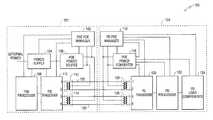
- FIG. 1is a schematic diagram of an example PoE system 100 in which an example embodiment of a PSE 101 provides power to an example embodiment of a PD 103 using PoE.
- PSE 101includes a PSE PoE manager 102 , a power supply 104 , a PoE power source 106 , a PSE processor 108 , a PSE transceiver 110 , a PSE capacitive signal first coupling transformer 112 , and a PSE capacitive signal second coupling transformer 114 .
- PSE PoE manager 102includes a PSE PoE manager 102 , a power supply 104 , a PoE power source 106 , a PSE processor 108 , a PSE transceiver 110 , a PSE capacitive signal first coupling transformer 112 , and a PSE capacitive signal second coupling transformer 114 .
- PD 103includes a PD PoE manager 116 , a POE power converter 118 , a PD transceiver 120 , a PD processor 122 , one or more PD load components 124 , a PD capacitive signal first coupling transformer 126 , and a PD capacitive signal second coupling transformer 128 .
- PSE PoE manager 102dynamically controls the PoE power applied by PoE power source 106 to selected Ethernet cable wire-pairs of one or more PoE enabled ports based on communication between the PSE 101 and one or more PDs, as described in greater detail below.
- PSE PoE manager 102is powered by power supply 104 , communicates with one or more of PSE processor 108 , PSE transceiver 110 and PoE power source 106 , and monitors POE wire-pairs on each PoE enabled port to detect cable connections/disconnection, and may monitor PoE power usage over the respective PoE enabled ports, as described in greater detail below.
- Power supply 104receives power from an external power source, not shown, and converts and/or conditions the received power. As shown in FIG. 1 , the converted/conditioned power is then used to power PSE PoE manager 102 , PoE power source 106 , PSE processor 108 , and PSE transceiver 110 .
- PSE power source 106receives power from power supply 104 and converts and/or conditions the power to produce a PoE DC voltage power signal that is transmitted to powered device 103 via selected PoE wire-pairs, e.g., first PoE power transmission wire-pair 130 and second PoE power transmission wire-pair 132 , associated with a PoE enabled port.
- PoE power source 106dynamically allocates power to a PoE enabled port based on configuration instructions received from PSE PoE manager 102 , as described below.
- first PoE power transmission wire-pair 130which includes cable conductor #1 and cable conductor #2
- second PoE power transmission wire-pair 132which includes cable conductor #3 and cable conductor #6
- the cable pairs used to transmit power from the PSE to the PDmay vary.
- PSE transceiver 110supports physical layer communication with a PD via network communication cable wire-pairs in accordance with a selected wire-based transmission protocol, e.g., 802.3 Ethernet 10/100 Mbps or other transmission protocol.
- PSE transceiver 110may be included in a network interface card (NIC) that supports one or more network ports, each port supporting data communication via a network communication cable that connects the port to a communication port on another device, e.g., a PD 103 , as shown in FIG. 1 .
- NICnetwork interface card
- PSE transceiver 110receives power from power supply 104 and communicates with one or more of PSE processor 108 and PSE PoE manager 102 to implement process flows described below with respect to FIG. 4 though FIG. 8 .
- PSE processor 108provides PSE 101 with processing capabilities based on the execution of programmed instructions stored in memory and/or in firmware. With respect to the implementation of PoE management, PSE processor 108 may receiver power from power supply 104 and may communicate with PSE PoE manager 102 and PSE transceiver 110 to implement the process flows described below with respect to FIG. 4 through FIG. 8 . For example, PSE processor 108 may communicate with PSE PoE manager 102 and may instruct PSE transceiver 110 to transmit PoE related messages generated by PSE PoE manager 102 , e.g., LLDP compliant messages, between PSE 101 and PD 103 containing information used to dynamically manage the delivery of PoE power from PSE 101 to PD 103 , as described in greater detail below. Although shown in FIG. 1 as separate modules, in on example PSE embodiment, PSE PoE manager 102 , PSE transceiver 110 and PSE processor 108 , may be implemented on a single integrated circuit system on a chip.
- PD PoE manager 116manages communication between PSE 101 and PD 103 related to the delivery of PoE power from PSE 101 to PD 103 , as described below with respect to the process flows shown in FIG. 5 and FIG. 7 .
- PD PoE manager 116communicates with one or more of PD transceiver 120 , PD processor 122 , and one or more PD load components 124 and relays requests for increases and/or decreases in power levels to PSE 101 .
- PD PoE manager 116may communicate with PoE power converter 118 to configure PoE power converter 118 to convert/condition PoE power received from PSE 101 to meet the respective power requirements of PD PoE manager 116 , PD transceiver 120 , PD processor 122 , and one or more PD load components 124 .
- POE power converter 118receives PoE power from PSE 101 via data network communication cable wire-pairs and converts and/or conditions the received power to meet the power requirements of one or more of PD PoE manager 116 , PD transceiver 120 , PD processor 122 , and one or more PD load components 124 , based on control signals received from PD PoE manager 116 .
- PoE power converter 118retrieves PoE power from center-taps included on PD capacitive signal first coupling transformer 126 attached to first PoE power transmission wire-pair 130 and PD capacitive signal second coupling transformer 128 attached to second PoE power transmission wire-pair 132 .
- the PoE powermay be received at a predetermined or dynamically negotiated voltage level and may be capable of providing a predetermined or dynamically negotiated maximum current at the designated voltage level.
- PoE power converter 118may convert and/or condition the received PoE power to meet specific power requirements of PD PoE manager 116 , PD transceiver 120 , PD processor 122 , and one or more PD load components 124 based on instructions received from PD PoE manager 116 .
- PD transceiver 120supports physical layer communication with a PSE via network communication cable wire-pairs in accordance with a selected wire-based transmission protocol, e.g., 802.3 Ethernet 10/100 Mbps or other transmission protocol.
- PD transceiver 120may be included in a network interface card (NIC) that supports a network port that supports data communication via a network communication cable that connects the port to a communication port on another device, e.g., a PSE, as shown in FIG. 1 .
- NICnetwork interface card
- NICnetwork interface card
- PD transceiver 120receives power from PoE power converter 118 and communicates with one or more of PD processor 122 and PD PoE manager 116 to implement process flows described below with respect to FIG. 4 though FIG. 8 .
- PD processor 122provides PD 103 with processing capabilities based on the execution of programmed instructions stored in memory and/or in firmware. With respect to the implementation of PoE management, PD processor 122 may receiver power from PoE power converter 118 and may communicate with PD PoE manager 116 , PD transceiver 120 and/or one or more PD load components, as described below.
- PD processor 122may communicate with PD PoE manager 116 and may instruct PD transceiver 120 to transmit PoE related messages generated by PD PoE manager 116 , e.g., LLDP compliant messages, between PD 103 and PSE 101 containing information used to dynamically manage the delivery of PoE power from PSE 101 to PD 103 , as described in greater detail below.
- PoE manager 116 , PD transceiver 120 and PD processor 122may be implemented on a single integrated circuit system on a chip.
- PD load components 124may include any embedded component or dynamically attachable component that draws power from PoE 103 .
- embedded components that may be included in a PD 103 that is a CCD cameraare a CCD imaging device, and/or an auto-focus device.
- dynamically attachable components included in such an example CCD camera that may affect the PoE power requirements of the PDmay include such items as an optional, large-sized memory chip, a flash-drive or a remote controlled pivoting base.
- the PoE power requirements of a PoE enabled portmay change based on the nature of the PD attached to the port and/or the dynamically configurable components with which the PD is configured. As the PoE requirements of the PD 103 change, the PD 103 may negotiate with PSE 101 to received either a decreased or increased PoE power allocation, as described in greater detail below.
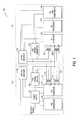
- FIG. 2is block diagram of an example PSE PoE manager 102 included in PSE 101 , described above with respect to FIG. 1 .
- PSE PoE manager 102includes a PSE controller 202 , a PSE power level module 204 , a PSE supply control module 206 , a PSE data store 208 , a PSE detection module 210 , and a PSE interface module 212 .
- PSE controller 202maintains a set of static and/or dynamically updated control parameters that can be used by PSE controller 202 to invoke the other modules included PSE PoE manager 102 to perform operations, as described below, in accordance with the control parameters and a set of predetermined process flows, such as those described below with respect to FIG. 4 through FIG. 8 .
- PSE controller 202may communicate with and receive status updates from the respective modules within PSE PoE manager 102 to allow PSE controller 202 to control operation of PSE 101 in support of the respective process flows.
- PSE data store 208is a local data store that stores a defined set of data, or protocol data unit (PDU), for each PoE enabled port supported by the PSE.
- the data included in each PoE enabled port PDUincludes configuration data and status information that is used to control operation of the port, as described below.
- each PoE port PDUmay include such values as a port identifier, a port maximum PoE voltage, a port maximum PoE current, a port maximum PoE power, and a port connection status.
- the PoE port PDUmay also include information about a PoE PD connected to the port such as a PD type, a present port PoE voltage, a present port maximum PoE current, a present port maximum PoE power, a requested port PoE voltage, a requested port maximum PoE current, and a requested port maximum PoE power.
- a description of such example PSE PDU parametersis provided in Table 1.
- Example PSE PDU ParametersExample PSE PDU Parameter Description PSE_port_identifier Unique PSE port identifier PSE_port_maximum_POE_voltage Maximum voltage that PSE will allow to be applied to port identified with port_identifier under any condition PSE_port_maximum_POE_current Maximum current that PSE will allow to pass through port identified with port_identifier under any condition PSE_port_maximum_POE_power Maximum total power that PSE will allow to pass through port identified with port_identifier under any condition PSE_port_connection_status Indicates whether the port identified with port_identifier is connected to a PD PD_type Associates a PD connected to port identified with port_identifier with a set of PD power requirements, e.g., initial power requirements and/or predefined power levels PD_present_port_POE_voltage Present voltage applied by PSE to port identified with port_identifier PD_present_port_maximum_POE_current Present maximum current that will be allowed
- portions of the PoE port PDU data stored in PSE data store 208may be stored as part of an initial PSE configuration process performed at the factory, and/or during installation of the PSE in a network configuration.
- PoE port PDU data stored in PSE data store 208may be dynamically updated based on a current status of power being delivered from the PSE to a PD and based on PoE related communication between the PSE and PDs connected to the respective ports, as described below with respect to FIG. 5 through FIG. 8 .
- a PSEreceives data related to a PD connected to a PSE port via periodic link layer discovery protocol (LLDP) broadcasts received from the PD connected to the PSE port.
- the data received in the LLDP broadcastis used to update data stored in the PSE PDU for the port on which the LLDP message was received.
- a change in the data stored in the PSE PDUcan be used to initiate action by the PSE PoE manager 102 to modify, for example, the voltage and/or maximum power assigned to a PoE enabled port, as described in greater detail below.
- Data exchanges between the PSE and PD devicesallow the PSE to negotiate PoE power assignments to meet the actual needs of the respective PD devices to the greatest extent possible with the finite amount of PoE power available for distribution by the PSE, and allows PoE power to be conserved and/or directed elsewhere when a PD does not require a previously negotiated power level.
- PSE 101 and PD 103may share a set of predefined power levels, each predefine power level associated with, for example, a port PoE voltage, a port maximum PoE current, and a port maximum PoE power.
- a predefined power levelsuch as “processor-idle-mode” may be passed from PD 103 to intelligent PSE 101 to convey one or more of a requested port PoE voltage, a requested port maximum PoE current, and a requested port maximum PoE power.
- a PSEis able to retrieve over the network a lookup table containing a set of predefined power levels associate with a PD 103 , based on a PD type received from the PD 103 .
- the lookup tableis pre-loaded into PSE 101 .
- the lookup tableis transmitted to PDE 101 from PD 103 , immediately after startup of PD 103 .
- Other techniques for establishing a common set of predefined power levels between a PSE 101 and a PD 103may also be used.
- PSE detection module 210determines whether a PoE enabled PD is connected to a PoE enabled PSE port, and determines an initial PoE power level, e.g., an initial voltage and an initial maximum current, that PSE 101 is to apply to the PoE enabled port on which the new PD is detected. For example, based on established PoE techniques, PSE detection module 210 may monitor a resistance between a predetermined set of wire-pairs on a PoE enabled port. On connection of a PD to the PoE enabled port via a communication network cable, the monitored resistance will change.
- an initial PoE power levele.g., an initial voltage and an initial maximum current
- PSE detection module 212can determine wither the device connected to the PoE enabled port is a PoE enabled PD, and can further determine, again based on the measured resistance value, an initial voltage and an initial maximum current to assign to the PoE enabled port.
- Information determined by PSE detection module 212may be stored in the PoE PDU for the port, e.g., as values stored in port connection status, PD type, present port PoE voltage, present port maximum PoE current, and present port maximum PoE power, stored in PSE data store 208 , and may be used by PSE supply control module 206 to control the voltage and power applied to the PoE enabled port by PoE power source 106 .
- PSE interface module 212coordinates communication, i.e., exchanges of data, between PSE 101 and PD 103 that are used to coordinate changes in the PoE power delivered from PSE 101 to a PD 103 .
- PSE interface module 212may parse incoming LLDP messages for data, extract and store received data in the PSE PDU corresponding to the PoE port on which the LLDP message was received, and may notify PSE controller 202 of any changes in the stored data on which action is required. Further, on request from PSE controller 202 , PSE interface module 212 may generate message content for inclusion in an LLDP broadcast from the PSE based on PDU data stored in PSE data store 208 for a port designated by PSE controller 202 .
- receipt of a requested port PoE voltage, requested port maximum PoE current, and/or requested port maximum PoE power that is less than the corresponding present port PoE voltage, present port maximum PoE current, and/or present port maximum PoE power stored in the PSE PDU for the portindicates that a power reduction has been requested by the PD, and indicates that a reassessment by the PSE of the power delivered by the PSE to the PD is required.
- Receipt of a requested port PoE voltage, requested port maximum PoE current, and/or requested port maximum PoE power that is greater than the corresponding present port PoE voltage, present port maximum PoE current, and/or present port maximum PoE power stored in the PSE PDU for the portindicates that a power increase has been requested by the PD, and indicates that a reassessment by the PSE of the power delivered by the PSE to the PD is required.
- PSE controller 202may instruct PSE interface module 212 to generate message content for inclusion in an LLDP broadcast from the PSE to the PD that includes PDU data stored in PSE data store 208 that has been updated based on the PSE's response to the request.
- the PDmay be informed whether an outstanding request for increased or decreased power has been implemented by the PSE and may update the corresponding PD PDU in PD data store 308 to reflect the updated data received in the LLDP message.
- POE power level module 204assesses new power level data received for a port from a PD device 103 , e.g., via an LLDP broadcast message transmitted from the PD 103 , based on data stored in association with the port in PSE data store 208 , and a knowledge of power constraints under which the PSE is configured to operate. For example, as described in greater detail below, in response to a request for additional power, PoE power level module 204 may determine whether the new power level can be granted based on a maximum threshold set for the respective PDs, current power commitments that have been made by the PSE 101 , required power reserve safety margins, and the priority of the power increase request.
- PSE supply control module 206generates control signals that are sent by PSE PoE manager 102 to PoE power source 106 , described above with respect to FIG. 1 , based on decisions made by PoE power level module 204 regarding the granting or denying of a change in power provided to a port.
- PoE power source 106may increase or decrease one of an applied voltage and/or maximum current cutoff level applied by PoE power source 106 to a wire-pair associated with a port based on control signals provided by PSE supply control module 206 .
- FIG. 3is block diagram of an example PD PoE manager 116 included in the PD 103 shown in FIG. 1 .
- PD PoE manager 116includes a PD controller 302 , a PD power level module 304 , a PD power monitoring module 306 , a PD data store 308 , and a PD interface module 312 .
- PD controller 302maintains a set of static and/or dynamically updated control parameters that can be used by PD controller 302 to invoke the other modules included in PD PoE manager 116 to perform operations, as described below, in accordance with the control parameters and a set of predetermined process flows, such as those described below with respect to FIG. 4 through FIG. 8 .
- PD controller 302may communicate with and receive status updates from the respective modules within PD PoE manager 116 to allow PD controller 302 to control operation of PD 103 in support of the respective process flows.
- PD data store 308is a local data store that is used to store control data and/or descriptive data related to features and/or characteristics of PD 103 . Portions of the data stored in PD data store 308 may be configured manually via a user interface. Other portions of the data stored in PD data store 308 may be dynamically maintained by, for example, PD controller 302 , based on changing operational conditions. In one example embodiment, PD data store 308 contains data similar to that described above with respect to the PoE port PDU data stored in PSE data store 208 , as described below, an example of which is described above with respect to Table 1.
- Values contained in fields such as requested port PoE voltage, requested port maximum PoE current and requested port maximum PoE powermay be calculated by, for example, PD power level module 304 , described below, based on power requirements updates received from one or more of PD transceiver 120 , PD processor 122 , and one or more PD load components 124 , and values stored in PD data store 308 fields such as present port PoE voltage, present port maximum PoE current, and present port maximum PoE power, as described in greater detail with respect to FIG. 4 , FIG. 5 , and FIG. 7 .
- PD data store 308is a local data store that stores a defined set of data, or protocol data unit (PDU), for one or more PoE enabled ports supported by the PD. Similar to a PSE port PDU described above with respect to FIG. 2 , the data included in each PD port PDU includes configuration data and status information that is used to control operation of the port, which may include PoE related communication with a PSE, as described below.
- each PD PoE port PDUmay include such values as a port identifier, a port maximum PoE voltage, a port maximum PoE current, a port maximum PoE power, and a port connection status.
- the PoE port PDUmay also include information about the PoE PD such as a PD type, a present port PoE voltage, a present port maximum PoE current, a present port maximum PoE power, a requested port PoE voltage, a requested port maximum PoE current, and a requested port maximum PoE power.
- information about the PoE PDsuch as a PD type, a present port PoE voltage, a present port maximum PoE current, a present port maximum PoE power, a requested port PoE voltage, a requested port maximum PoE current, and a requested port maximum PoE power.
- a description of such example PSE PDU parametersmay match those described above with respect to Table 1.
- portions of the PD port PDU data stored in PD data store 308may be stored as part of an initial configuration process performed at the factory, and/or during installation of the PD in a network configuration.
- Other portions of the PD port PDU data stored in PD data store 308are dynamically updated based on a current status of power consumed by the PD and based on PoE related communication between the PD and a PSE that supplies power to the PD, as described below with respect to FIG. 5 through FIG. 8 .
- the PDupdates the PD PDU and periodically generates LLDP compliant messages that are transmitted over the PD PoE port via PD transceiver 120 .
- the PDmay receive and process LLDP compliant messages transmitted from a PSE from which the PD receives PoE power.
- the data received in the LLDP broadcastis used to update data stored in the PD PDU for the PoE port.
- a change in the data stored in the PD PDUcan be used to initiate action by the PD PoE manager 116 to, for example, notify load components that a requested increase in power is available for use.
- Data exchanges between the PD and PSE devicesallow the PD to negotiate PoE power assignments to meet the actual needs of the respective PD load components based on the amount of power available from the PSE, and allows the PD to help the PSE conserve PoE power for use by other network PDs when a PD does not require a previously negotiated power level.
- PD power level module 304generates power requirements data for PD device 103 based on data stored in PD data store 308 and/or power requirements updates received from one or more of PD transceiver 120 , PD processor 122 , and one or more PD load components 124 .
- the generated power levelis stored in PD data store 308 , e.g., as requested port PoE voltage, requested port maximum PoE current and requested port maximum PoE power, and made available to PSE PoE manager 102 , as described in greater detail with respect to FIG. 5 and FIG. 7 , e.g., via an LLDP broadcast from PD 103 .
- PD power monitoring module 306monitors power received from PSE 101 and monitors the distribution of power from power converter 118 to verify that power is being received and distributed in a manner consistent with data stored in PD data store 308 .
- Error conditionssuch as the receipt of PoE power from a PSE that falls below negotiated voltage/power levels, e.g., due to cable loss, or such as power use by PD load components that exceeds one or more internal thresholds, or such as power use by PD load components that falls below one or more internal PD threshold levels, is reported to PD controller 302 and may be used to initiate action on the part of PD controller 302 to negotiate an increase and/or decrease in power received from the PSE.
- PD interface module 312coordinates communication, i.e., exchanges of data, between PD 103 and PSE 101 that are used to coordinate changes in the PoE power delivered from PSE 101 to PD 103 .
- PD interface module 312may generate message content for inclusion in an LLDP broadcast from the PD based on PD port PDU data stored in PD data store 308 for a port designated by PD controller 302 .
- PD controller 302is notified by one or more of PD transceiver 120 , PD processor 122 and one or more of PD load components 124 when the respective devices enter a mode that requires reduced power consumption, such as a power idle mode, a sleep mode, or a reduced data communication rate mode, or other mode that results in the PD requiring less power.
- PD controller 302instructs PD power level module 304 to reassess the total power requirements for PD 103 based, for example, on PD port PDU power consumption data stored in PD data store 308 and the newly received power requirements update.
- PD controller 302my instruct PD interface module 312 to generate an LLDP based message that notifies the PSE 101 of the reduced PD power requirement, e.g., via an LLDP broadcast message that includes reduced power requirements in one or more of requested port PoE voltage, requested port maximum PoE current, and/or requested port maximum PoE power.
- PD controller 302is notified by one or more of PD transceiver 120 , PD processor 122 and one or more of PD load components 124 when the respective devices enter a mode that requires increased power consumption, such as a full operational mode, activation of a math co-processor, a mode that entails the PD transceiver 120 supporting a higher transmission rate that requires increased power consumption, or other mode that results in the PD requiring more power.
- PD controller 302instructs PD power level module 304 to reassess the total power requirements for PD 103 based, for example, on PD port PDU power consumption data stored in PD data store 308 and the newly received power requirements update.
- PD controller 302my instruct PD interface module 312 to generate an LLDP based message that notifies the PSE 101 of the increased PD power requirement, e.g., via an LLDP broadcast message that includes increased power requirements in one or more of requested port PoE voltage, requested port maximum PoE current, and/or requested port maximum PoE power.
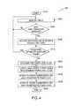
- FIG. 4is a flow-chart of an example process for starting up a PD 103 with power from a PSE 101 . As shown in FIG. 4 , operation of the process begins at S 402 and proceeds to S 404 .
- PSE detection module 210monitors PoE enabled ports provided by PSE 101 to detect connection of a network cable to one of the respective ports by, for example, monitoring a resistance between a predetermined set of wire-pairs, and operation of the process continues at S 406 .
- PSE detection module 210measures the value of the resistance detected between the monitored PoE pairs, and operation of the process continues at S 410 .
- PSE detection module 210determines the PoE power class of the attached PD and stores the determined PoE power class in PSE data store 208 , either directly or via PSE controller 202 , and operation of the process continues at S 414 .
- PSE controller 202instructs PSE supply control module 206 to control PoE power source 106 to supply power to the port based on the voltage and power requirements associated with the determined PoE power class, and operation of the process continues at S 416 .
- PSE controller 202receives, e.g., via PSE interface module 212 , a communication, e.g., an LLDP broadcast message, from the attached PD containing a set of one or more predefined power levels associated with the PD, and the power requirements associated with each, and operation of the process continues at S 418 .
- a communicatione.g., an LLDP broadcast message
- PSE controller 202stores the predefined power levels and the power requirements associated with each in PSE data store 208 , and operation of the process terminates at S 420 .
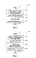
- FIG. 5a flow-chart of an example process performed by a PD to inform a PSE of a reduced PD power requirement. As shown in FIG. 5 , operation of the process begins at S 502 and proceeds to S 504 .
- PD controller 302receives a notification of reduced power consumption from PD transceiver 120 , PD processor 122 or a PD load component 124 , and operation of the process continues at S 506 .
- PD controller 302invokes PD power level module 304 to determine the new PD power level for the PD, e.g., based on the prior PD power level and the reported reduction in power requirements, and operation of the process continues at S 508 .
- PD power level module 304stores the determined power level in PD data store 308 , either directly or via PSE controller 202 , and operation of the process continues at S 510 .
- PD controller 302initiates a broadcast message over the PD communication port via, for example, PD transceiver 120 , to notify PSE 101 of the change in power requirements, and operation of the process terminates at S 512 .
- FIG. 6a flow-chart of an example process performed by a PSE 101 in response to being informed by a PD 103 of a reduced power requirement. As shown in FIG. 6 , operation of the process begins at S 602 and proceeds to S 604 .
- PSE controller 202receives a notification of a new power level indicating a reduced power requirement, and operation of the process continues at S 606 .
- PSE controller 202updates port data in PSE data store 208 associated with the port on which the notification is received with the new power level, and operation of the process continues at S 608 .
- PSE controller 202invokes PSE power level module 204 to determine the new power requirements for the PD, e.g., based on the received power level and a power level lookup table associated with the PD 103 from which the power level was received, and operation of the process continues at S 610 .
- PSE controller 202invokes PSE supply control module 206 to configure PoE power source 106 to provide PoE power to the PD 103 based on the determined power requirements for the port, and operation of the process terminates at S 612 .
- FIG. 7is a flow-chart of an example process performed by a PD 103 to inform a PSE 101 of an increased PD power requirement. As shown in FIG. 7 , operation of the process begins at S 702 and proceeds to S 704 .
- PD controller 302receives a request for increased power consumption from PD transceiver 120 , PD processor 122 or a PD load component 124 , and operation of the process continues at S 706 .
- PD controller 302invokes PD power level module 304 to determine the new PD power level for the PD, e.g., based on the prior PD power level and the reported reduction in power requirements, and operation of the process continues at S 708 .
- PD controller 302initiates a broadcast message over the PD communication port via, for example, PD transceiver 120 , to notify PSE 101 of the change in power requirements, and operation of the process continues at S 710 .
- PD controller 302notifies the requesting PD unit, e.g., PD transceiver 120 , PD processor 122 or a PD load component 124 , that the requested power increase was denied, and operation of the process terminates at S 718 .
- PD unite.g., PD transceiver 120 , PD processor 122 or a PD load component 124
- PD controller 302notifies the requesting PD unit, e.g., PD transceiver 120 , PD processor 122 or a PD load component 124 , that the requested power increase was allowed, and operation of the process continues at S 714 .
- PD unite.g., PD transceiver 120 , PD processor 122 or a PD load component 124
- PD controller 302stores the determined granted power level in PD data store 308 in association with the PD port, and operation of the process terminates at S 718 .
- FIG. 8a flow-chart of an example process performed by a PSE 101 in response to being informed of an increased PD power requirement by a PD 103 . As shown in FIG. 8 , operation of the process begins at S 802 and proceeds to S 804 .
- PSE controller 202receives a request for an increased power allocation from a PD, and operation of the process continues at S 806 .
- PSE controller 202invokes PSE power level module 204 to determine a new power level for the PD, e.g., based on the received power level and a power level lookup table associated with the PD 103 from which the power level was received, and operation of the process continues at S 808 .
- PSE controller 202determines that the determined new power level is below a maximum allowed power allocation assigned to the port, e.g., a maximum allowed power allocation stored in PSE data store 208 in association with the port, operation of the process continues at S 810 ; otherwise, operation of the process continues at S 818 .
- a maximum allowed power allocation assigned to the porte.g., a maximum allowed power allocation stored in PSE data store 208 in association with the port
- PSE controller 202notifies the requesting PD unit that the requested power increase was not allowed, and operation of the process terminates at S 820 .
- PSE controller 202updates port data in PSE data store 208 associated with the port on which the notification is received with the new power level, and operation of the process continues at S 814 .
- PSE controller 202invokes PSE supply control module 206 to configure PoE power source 106 to provide PoE power to the PD 103 based on the updated power requirements for the port, and operation of the process continues at S 816 .
- PSE controller 202notifies the requesting PD unit that the requested power increase was allowed, e.g., via an LLDP message that indicates a present power level that matches the requested power level requested by the requesting PD, and operation of the process terminates at S 820 .
- example embodiments of PSE 101may include a PSE PoE manager that tracks power usage by the PD 103 devices supported by the PSE 101 .
- PSE 101may use such information to generate day/time based usage data that maybe used by PSE 101 to refine PoE allocations. For example, if PSE 101 determines that certain PD 103 device enter a low power state after business hours and on weekends and holidays, PSE 101 may use that information when deciding whether to grant increases in PoE power from other PoE PD devices during those times.
- an PSEmay maintain a PD power requirements lookup table that includes one or more predefined PD types, each predefined PD type having one or more power level states with predetermined power requirements.
- the PSEis preconfigured with the PD power requirements lookup table during the manufacturing or installation process.
- the PSEbuilds the PD power requirements lookup table based on PD types, power level states, and predetermined power requirements reported by the respective PD devices supported by the PSE.
- the PSE port PDU datamay be made available to network management applications executed by one or more network connected devices using communication protocols other than LLDP.
- power management applicationsmay retrieve allocated power and actual use power data from the respective PSE and PD devices using the simple network management protocol (SNMP).
- SNMPsimple network management protocol
- the PDmay report to a PSE one or more of an explicit power requirement, an explicit positive incremental change in a power requirement, an explicit negative incremental change in a power requirement, a predefined power level that corresponds to a predetermined power requirement of which the PSE has been previously informed and/or has previously stored in a PD power requirements lookup table, as described above.
- a PD and a PSEmay exchange PoE power related information using any desired standard, or non-standard communication protocol, and that such communication protocols are not limited to those used in the example embodiments describe above.
Landscapes
- Engineering & Computer Science (AREA)
- General Engineering & Computer Science (AREA)
- Theoretical Computer Science (AREA)
- Computer Networks & Wireless Communication (AREA)
- Signal Processing (AREA)
- Computer Hardware Design (AREA)
- Physics & Mathematics (AREA)
- General Physics & Mathematics (AREA)
- Small-Scale Networks (AREA)
Abstract
Description
| TABLE 1 |
| Example PSE PDU Parameters |
| Example PSE PDU Parameter | Description |
| PSE_port_identifier | Unique PSE port identifier |
| PSE_port_maximum_POE_voltage | Maximum voltage that PSE will allow to be |
| applied to port identified with | |
| port_identifier under any condition | |
| PSE_port_maximum_POE_current | Maximum current that PSE will allow to |
| pass through port identified with | |
| port_identifier under any condition | |
| PSE_port_maximum_POE_power | Maximum total power that PSE will allow |
| to pass through port identified with | |
| port_identifier under any condition | |
| PSE_port_connection_status | Indicates whether the port identified with |
| port_identifier is connected to a PD | |
| PD_type | Associates a PD connected to port identified |
| with port_identifier with a set of PD power | |
| requirements, e.g., initial power | |
| requirements and/or predefined power | |
| levels | |
| PD_present_port_POE_voltage | Present voltage applied by PSE to port |
| identified with port_identifier | |
| PD_present_port_maximum_POE_current | Present maximum current that will be |
| allowed by PSE to pass through port | |
| identified with port_identifier at present | |
| voltage | |
| PD_present_port_maximum_POE_power | Present maximum power that will be |
| allowed by PSE through port identified with | |
| port_identifier | |
| PD_requested_port_POE_voltage | Voltage requested by PD for application to |
| port identified with port_identifier | |
| PD_requested_port_maximum_POE_current | Maximum current requested by PD for |
| application to port identified with | |
| port_identifier at requested voltage | |
| PD_requested_port_maximum_POE_power | Maximum power requested by PD for |
| application to port identified with | |
| port_identifier | |
Claims (14)
Priority Applications (1)
| Application Number | Priority Date | Filing Date | Title |
|---|---|---|---|
| US12/722,970US8793511B1 (en) | 2009-03-23 | 2010-03-12 | Power management for power over ethernet (PoE) system based on network communication transmission rate |
Applications Claiming Priority (2)
| Application Number | Priority Date | Filing Date | Title |
|---|---|---|---|
| US16258509P | 2009-03-23 | 2009-03-23 | |
| US12/722,970US8793511B1 (en) | 2009-03-23 | 2010-03-12 | Power management for power over ethernet (PoE) system based on network communication transmission rate |
Publications (1)
| Publication Number | Publication Date |
|---|---|
| US8793511B1true US8793511B1 (en) | 2014-07-29 |
Family
ID=51212199
Family Applications (1)
| Application Number | Title | Priority Date | Filing Date |
|---|---|---|---|
| US12/722,970Active2031-03-04US8793511B1 (en) | 2009-03-23 | 2010-03-12 | Power management for power over ethernet (PoE) system based on network communication transmission rate |
Country Status (1)
| Country | Link |
|---|---|
| US (1) | US8793511B1 (en) |
Cited By (38)
| Publication number | Priority date | Publication date | Assignee | Title |
|---|---|---|---|---|
| US20130297955A1 (en)* | 2011-03-14 | 2013-11-07 | Cisco Technology, Inc. | Directing a power signal from a port power controller to one of multiple physical ports |
| US20130314556A1 (en)* | 2012-05-28 | 2013-11-28 | Canon Kabushiki Kaisha | Network camera and control method therefor |
| US20140129854A1 (en)* | 2012-11-07 | 2014-05-08 | Broadcom Corporation | Auto-Negotiation and Advanced Classification for Power Over Ethernet (POE) Systems |
| US20140245054A1 (en)* | 2012-11-07 | 2014-08-28 | Dell Products L.P. | Power over ethernet dynamic power allocation system |
| US20150026489A1 (en)* | 2011-06-09 | 2015-01-22 | Andrew Llc | Distributed antenna system using power-over-ethernet |
| CN104618123A (en)* | 2015-01-21 | 2015-05-13 | 杭州华三通信技术有限公司 | Power supply method and device |
| US20160226667A1 (en)* | 2013-09-13 | 2016-08-04 | Nec Corporation | Radio communication device and method for controlling radio communication device |
| US9535437B1 (en)* | 2012-10-15 | 2017-01-03 | Linear Technology Corporation | Power over ethernet power sourcing equipment provides low voltage output for increased efficiency in low power mode |
| US20170068307A1 (en)* | 2015-09-03 | 2017-03-09 | Cisco Technology, Inc. | Selection of power in power over ethernet systems |
| KR20170108456A (en)* | 2016-03-17 | 2017-09-27 | 현대자동차주식회사 | Power control method for power over data lines system |
| CN107409057A (en)* | 2015-03-11 | 2017-11-28 | 飞利浦灯具控股公司 | Rapid restoration of power supply via data link after power outage |
| US9847884B2 (en) | 2014-11-04 | 2017-12-19 | Cisco Technology, Inc. | Negotiable PoE voltage for improved efficiency based on cable and powered device losses |
| US9900164B2 (en)* | 2015-06-10 | 2018-02-20 | Cisco Technology, Inc. | Dynamic power management |
| US20180062674A1 (en)* | 2015-01-13 | 2018-03-01 | Physical Optics Corporation | Integrative software radio |
| US9927864B2 (en)* | 2014-06-27 | 2018-03-27 | Dell Products L.P. | Multiple link power allocation system |
| US9990020B2 (en) | 2015-07-07 | 2018-06-05 | Aruba Networks, Inc. | Use of link layer discovery protocol-media endpoint discovery to avoid false legacy powered device detection in power over ethernet systems and networks |
| US10095662B1 (en) | 2012-06-18 | 2018-10-09 | Bromium, Inc. | Synchronizing resources of a virtualized browser |
| US10310696B1 (en)* | 2010-05-28 | 2019-06-04 | Bromium, Inc. | Supporting a consistent user interface within a virtualized environment |
| US20190179390A1 (en)* | 2017-12-11 | 2019-06-13 | Denso Corporation | POE Power Supply System |
| US10327031B2 (en)* | 2014-11-14 | 2019-06-18 | Shenzhen Skyworth Digital Technology Co., Ltd | Playing control method and terminal |
| US10374895B2 (en) | 2016-03-11 | 2019-08-06 | Hewlett Packard Enterprise Development Lp | Configuration of communication interfaces for link aggregation |
| US10417143B2 (en)* | 2015-10-08 | 2019-09-17 | Esker Technologies, LLC | Apparatus and method for sending power over synchronous serial communication wiring |
| CN110247776A (en)* | 2018-03-09 | 2019-09-17 | 深圳市优特普电子有限公司 | A kind of PoE slow power supply unit, system and method |
| US20190327100A1 (en)* | 2015-12-22 | 2019-10-24 | Forescout Technologies, Inc. | Device identification and policy enforcement using power over ethernet (poe) |
| US20210083904A1 (en)* | 2016-07-18 | 2021-03-18 | Commscope Technologies Llc | Systems and methods for high capacity power delivery to remote nodes |
| US11023088B2 (en) | 2012-06-18 | 2021-06-01 | Hewlett-Packard Development Company, L.P. | Composing the display of a virtualized web browser |
| US11061456B2 (en)* | 2019-01-23 | 2021-07-13 | Cisco Technology, Inc. | Transmission of pulse power and data over a wire pair |
| US20220283625A1 (en)* | 2019-08-29 | 2022-09-08 | Signify Holding B.V. | Control network system for power allocation |
| US11444791B2 (en) | 2019-01-23 | 2022-09-13 | Cisco Technology, Inc. | Transmission of pulse power and data in a communications network |
| US11546178B2 (en)* | 2010-04-02 | 2023-01-03 | Commscope Technologies Llc | Method and apparatus for distributing power over communication cabling |
| US11743059B2 (en) | 2015-03-10 | 2023-08-29 | Huawei Technologies Co., Ltd. | Power over ethernet (PoE) power supplying method and apparatus |
| US11757664B2 (en)* | 2017-08-04 | 2023-09-12 | Electrical Engineering Solutions Pty Limited | PoE system for the distribution of high voltage power, data and lighting and a common mode signalling system incorporated therein |
| US11916614B2 (en) | 2019-11-01 | 2024-02-27 | Cisco Technology, Inc. | Initialization and synchronization for pulse power in a network system |
| US20240129862A1 (en)* | 2022-10-14 | 2024-04-18 | Cisco Technology, Inc. | Wireless local area network access point system configuration and power improvement |
| US12001255B2 (en) | 2014-09-02 | 2024-06-04 | Cisco Technology, Inc. | Persistent Power over Ethernet |
| CN118432961A (en)* | 2024-07-05 | 2024-08-02 | 浙江大华技术股份有限公司 | A power management method, a power management device and a computer storage medium |
| US12126399B2 (en) | 2019-11-01 | 2024-10-22 | Cisco Technology, Inc. | Fault managed power with dynamic and adaptive fault sensor |
| US12126456B2 (en) | 2019-03-13 | 2024-10-22 | Cisco Technology, Inc. | Multiple phase pulse power in a network communications system |
Citations (21)
| Publication number | Priority date | Publication date | Assignee | Title |
|---|---|---|---|---|
| US20060164769A1 (en)* | 2005-01-25 | 2006-07-27 | Linear Technology Corporation | Adjusting current limit thresholds based on power requirement of powered device in system for providing power over communication link |
| US20080256371A1 (en)* | 2007-04-11 | 2008-10-16 | Broadcom Corporation | System and method for power management in a computing device for power over ethernet |
| US7441133B2 (en)* | 2002-10-15 | 2008-10-21 | Microsemi Corp. - Analog Mixed Signal Group Ltd. | Rack level power management for power over Ethernet |
| US20090052372A1 (en)* | 2007-08-23 | 2009-02-26 | Cisco Technology, Inc. | Dynamic power usage management based on historical traffic pattern data for network devices |
| US20090210725A1 (en)* | 2008-02-14 | 2009-08-20 | Broadcom Corporation | Variable power over ethernet based on link delay measurement |
| US7613939B2 (en)* | 2006-03-14 | 2009-11-03 | Cisco Technology, Inc. | Method and apparatus for changing power class for a powered device |
| US7631201B2 (en)* | 2006-05-25 | 2009-12-08 | Foundry Networks, Inc. | System software for managing power allocation to Ethernet ports in the absence of mutually exclusive detection and powering cycles in hardware |
| US7706392B2 (en)* | 2005-08-19 | 2010-04-27 | Akras Silicon Inc. | Dynamic power management in a power over ethernet system |
| US7756544B1 (en)* | 2005-01-13 | 2010-07-13 | Enterasys Networks, Inc. | Power controlled network devices for security and power conservation |
| US7774628B2 (en)* | 2006-05-25 | 2010-08-10 | Foundry Networks, Inc. | Enabling/disabling power-over-ethernet software subsystem in response to power supply status |
| US7773354B2 (en)* | 2006-12-22 | 2010-08-10 | Silicon Laboratories, Inc. | Voltage protection circuit for power supply device and method therefor |
| US7814340B2 (en)* | 2005-12-12 | 2010-10-12 | Linear Technology Corporation | Power management mechanism in system for supplying power over communication link |
| US7832820B2 (en)* | 2006-10-31 | 2010-11-16 | Hewlett-Packard Development Company, L.P. | Regulating energy based on delivered energy |
| US7849333B2 (en)* | 2006-05-08 | 2010-12-07 | Cisco Technology, Inc. | Inline power allocation for power over Ethernet applications |
| US7908494B2 (en)* | 2007-09-26 | 2011-03-15 | Broadcom Corporation | System and method for multiple PoE power supply management |
| US7936546B2 (en)* | 2006-01-17 | 2011-05-03 | Broadcom Corporation | Apparatus and method for classifying a powered device (PD) in a power source equipment (PSE) controller |
| US8149602B2 (en)* | 2008-03-27 | 2012-04-03 | Microsemi Corp.-Analog Mixed Signal Group, Ltd. | Method and apparatus for detecting end of start up phase |
| US8225124B2 (en)* | 2008-07-30 | 2012-07-17 | Symbol Technologies, Inc. | Method and system for determining power over ethernet class capabilities |
| US20120228936A1 (en)* | 2009-01-05 | 2012-09-13 | Hazem Kabbara | Intelligent power management of an intermediate network device switching circuitry and poe delivery |
| US20120287829A1 (en)* | 2011-05-12 | 2012-11-15 | Micrel, Inc. | Adaptive pause time energy efficient ethernet PHY |
| US20120311169A1 (en)* | 2007-08-27 | 2012-12-06 | Yoshihiro Nakao | Network relay apparatus |
- 2010
- 2010-03-12USUS12/722,970patent/US8793511B1/enactiveActive
Patent Citations (23)
| Publication number | Priority date | Publication date | Assignee | Title |
|---|---|---|---|---|
| US7441133B2 (en)* | 2002-10-15 | 2008-10-21 | Microsemi Corp. - Analog Mixed Signal Group Ltd. | Rack level power management for power over Ethernet |
| US7756544B1 (en)* | 2005-01-13 | 2010-07-13 | Enterasys Networks, Inc. | Power controlled network devices for security and power conservation |
| US20060164769A1 (en)* | 2005-01-25 | 2006-07-27 | Linear Technology Corporation | Adjusting current limit thresholds based on power requirement of powered device in system for providing power over communication link |
| US7706392B2 (en)* | 2005-08-19 | 2010-04-27 | Akras Silicon Inc. | Dynamic power management in a power over ethernet system |
| US7814340B2 (en)* | 2005-12-12 | 2010-10-12 | Linear Technology Corporation | Power management mechanism in system for supplying power over communication link |
| US7936546B2 (en)* | 2006-01-17 | 2011-05-03 | Broadcom Corporation | Apparatus and method for classifying a powered device (PD) in a power source equipment (PSE) controller |
| US7613939B2 (en)* | 2006-03-14 | 2009-11-03 | Cisco Technology, Inc. | Method and apparatus for changing power class for a powered device |
| US8171315B2 (en)* | 2006-03-14 | 2012-05-01 | Cisco Technology, Inc. | Method and apparatus for changing power class for a powered device |
| US7849333B2 (en)* | 2006-05-08 | 2010-12-07 | Cisco Technology, Inc. | Inline power allocation for power over Ethernet applications |
| US7774628B2 (en)* | 2006-05-25 | 2010-08-10 | Foundry Networks, Inc. | Enabling/disabling power-over-ethernet software subsystem in response to power supply status |
| US7631201B2 (en)* | 2006-05-25 | 2009-12-08 | Foundry Networks, Inc. | System software for managing power allocation to Ethernet ports in the absence of mutually exclusive detection and powering cycles in hardware |
| US8001397B2 (en)* | 2006-05-25 | 2011-08-16 | Foundry Networks, Llc | System software for managing power allocation to Ethernet ports in the absence of mutually exclusive detection and powering cycles in hardware |
| US7832820B2 (en)* | 2006-10-31 | 2010-11-16 | Hewlett-Packard Development Company, L.P. | Regulating energy based on delivered energy |
| US7773354B2 (en)* | 2006-12-22 | 2010-08-10 | Silicon Laboratories, Inc. | Voltage protection circuit for power supply device and method therefor |
| US20080256371A1 (en)* | 2007-04-11 | 2008-10-16 | Broadcom Corporation | System and method for power management in a computing device for power over ethernet |
| US20090052372A1 (en)* | 2007-08-23 | 2009-02-26 | Cisco Technology, Inc. | Dynamic power usage management based on historical traffic pattern data for network devices |
| US20120311169A1 (en)* | 2007-08-27 | 2012-12-06 | Yoshihiro Nakao | Network relay apparatus |
| US7908494B2 (en)* | 2007-09-26 | 2011-03-15 | Broadcom Corporation | System and method for multiple PoE power supply management |
| US20090210725A1 (en)* | 2008-02-14 | 2009-08-20 | Broadcom Corporation | Variable power over ethernet based on link delay measurement |
| US8149602B2 (en)* | 2008-03-27 | 2012-04-03 | Microsemi Corp.-Analog Mixed Signal Group, Ltd. | Method and apparatus for detecting end of start up phase |
| US8225124B2 (en)* | 2008-07-30 | 2012-07-17 | Symbol Technologies, Inc. | Method and system for determining power over ethernet class capabilities |
| US20120228936A1 (en)* | 2009-01-05 | 2012-09-13 | Hazem Kabbara | Intelligent power management of an intermediate network device switching circuitry and poe delivery |
| US20120287829A1 (en)* | 2011-05-12 | 2012-11-15 | Micrel, Inc. | Adaptive pause time energy efficient ethernet PHY |
Non-Patent Citations (5)
| Title |
|---|
| Adtran Inc, LLDP and LLDP-MED, Mar. 2008, pp. 1-31.* |
| The Institute of Electrical and Electronics Engineers, Inc.; IEEE Standard for Information Technology-Telecommunications and Information Exchange Between Systems-Local and Metropolitan Area Networks-Specific Requirements; Part 3: Carrier Sense Multiple Access with Collision Detection (CSMA/CD) Access Method and Physical Layer Specifications; (Sections 1-5) IEEE Std. 802.3-2005 Dec. 9, 2005; New York, NY. |
| The Institute of Electrical and Electronics Engineers, Inc.; IEEE Standard for Information Technology—Telecommunications and Information Exchange Between Systems—Local and Metropolitan Area Networks—Specific Requirements; Part 3: Carrier Sense Multiple Access with Collision Detection (CSMA/CD) Access Method and Physical Layer Specifications; (Sections 1-5) IEEE Std. 802.3-2005 Dec. 9, 2005; New York, NY. |
| The Institute of Electrical and Electronics Engineers, Inc.; IEEE Standard for Information Technology-Telecommunications and Information Exchange Between Systems-Local and Metropolitan Area Networks-Specific Requirements; Part 3: Carrier Sense Multiple Access with Collision Detection (CSMA/CD) Access method and Physical Layer Specifications; IEEE Std. 802.3af-2003 (Amendment to IEEE Std. 802.3-2002) Jun. 18, 2003; New York, NY. |
| The Institute of Electrical and Electronics Engineers, Inc.; IEEE Standard for Information Technology—Telecommunications and Information Exchange Between Systems—Local and Metropolitan Area Networks—Specific Requirements; Part 3: Carrier Sense Multiple Access with Collision Detection (CSMA/CD) Access method and Physical Layer Specifications; IEEE Std. 802.3af-2003 (Amendment to IEEE Std. 802.3-2002) Jun. 18, 2003; New York, NY. |
Cited By (71)
| Publication number | Priority date | Publication date | Assignee | Title |
|---|---|---|---|---|
| US11546178B2 (en)* | 2010-04-02 | 2023-01-03 | Commscope Technologies Llc | Method and apparatus for distributing power over communication cabling |
| US10310696B1 (en)* | 2010-05-28 | 2019-06-04 | Bromium, Inc. | Supporting a consistent user interface within a virtualized environment |
| US9501122B2 (en)* | 2011-03-14 | 2016-11-22 | Cisco Technology, Inc | Directing a power signal from a port power controller to one of multiple physical ports |
| US20130297955A1 (en)* | 2011-03-14 | 2013-11-07 | Cisco Technology, Inc. | Directing a power signal from a port power controller to one of multiple physical ports |
| US20170115714A1 (en)* | 2011-03-14 | 2017-04-27 | Cisco Technology, Inc. | Directing a power signal from a port power controller to one of multiple physical ports |
| US10437302B2 (en)* | 2011-03-14 | 2019-10-08 | Cisco Technology, Inc. | Directing a power signal from a port power controller to one of multiple physical ports |
| US9544156B2 (en)* | 2011-06-09 | 2017-01-10 | Commscope Technologies Llc | Distributed antenna system using power-over-ethernet based on a resistance of a channel |
| US10261560B2 (en) | 2011-06-09 | 2019-04-16 | Commscope Technologies Llc | Distributed antenna system using power-over-ethernet |
| US20150026489A1 (en)* | 2011-06-09 | 2015-01-22 | Andrew Llc | Distributed antenna system using power-over-ethernet |
| AU2017200861B2 (en)* | 2011-06-09 | 2018-05-17 | Commscope Technologies Llc | Distributed antenna system using power-over-ethernet |
| US20130314556A1 (en)* | 2012-05-28 | 2013-11-28 | Canon Kabushiki Kaisha | Network camera and control method therefor |
| US11023088B2 (en) | 2012-06-18 | 2021-06-01 | Hewlett-Packard Development Company, L.P. | Composing the display of a virtualized web browser |
| US10095662B1 (en) | 2012-06-18 | 2018-10-09 | Bromium, Inc. | Synchronizing resources of a virtualized browser |
| US9535437B1 (en)* | 2012-10-15 | 2017-01-03 | Linear Technology Corporation | Power over ethernet power sourcing equipment provides low voltage output for increased efficiency in low power mode |
| US9110972B2 (en)* | 2012-11-07 | 2015-08-18 | Dell Products L.P. | Power over ethernet dynamic power allocation system |
| US20140245054A1 (en)* | 2012-11-07 | 2014-08-28 | Dell Products L.P. | Power over ethernet dynamic power allocation system |
| US20140129854A1 (en)* | 2012-11-07 | 2014-05-08 | Broadcom Corporation | Auto-Negotiation and Advanced Classification for Power Over Ethernet (POE) Systems |
| US10133648B2 (en) | 2012-11-07 | 2018-11-20 | Dell Products L.P. | Power over ethernet dynamic power allocation system |
| US20160226667A1 (en)* | 2013-09-13 | 2016-08-04 | Nec Corporation | Radio communication device and method for controlling radio communication device |
| US10177925B2 (en)* | 2013-09-13 | 2019-01-08 | Nec Corporation | Radio communication device and method for controlling radio communication device |
| US9927864B2 (en)* | 2014-06-27 | 2018-03-27 | Dell Products L.P. | Multiple link power allocation system |
| US12001255B2 (en) | 2014-09-02 | 2024-06-04 | Cisco Technology, Inc. | Persistent Power over Ethernet |
| US9847884B2 (en) | 2014-11-04 | 2017-12-19 | Cisco Technology, Inc. | Negotiable PoE voltage for improved efficiency based on cable and powered device losses |
| US10327031B2 (en)* | 2014-11-14 | 2019-06-18 | Shenzhen Skyworth Digital Technology Co., Ltd | Playing control method and terminal |
| US10511337B2 (en)* | 2015-01-13 | 2019-12-17 | Physical Optics Corporation | Integrative software radio |
| US20180062674A1 (en)* | 2015-01-13 | 2018-03-01 | Physical Optics Corporation | Integrative software radio |
| CN104618123A (en)* | 2015-01-21 | 2015-05-13 | 杭州华三通信技术有限公司 | Power supply method and device |
| CN104618123B (en)* | 2015-01-21 | 2018-10-26 | 新华三技术有限公司 | A kind of method of supplying power to and device |
| US12119946B2 (en) | 2015-03-10 | 2024-10-15 | Huawei Technologies Co., Ltd. | Power over ethernet (PoE) power supplying via two sets of cable pairs |
| US11743059B2 (en) | 2015-03-10 | 2023-08-29 | Huawei Technologies Co., Ltd. | Power over ethernet (PoE) power supplying method and apparatus |
| CN107409057A (en)* | 2015-03-11 | 2017-11-28 | 飞利浦灯具控股公司 | Rapid restoration of power supply via data link after power outage |
| US20180052504A1 (en)* | 2015-03-11 | 2018-02-22 | Philips Lighting Holding B.V. | Rapid resumption of a power supply via a data link after power outage |
| US10539994B2 (en)* | 2015-03-11 | 2020-01-21 | Signify Holding B.V. | Rapid resumption of a power supply via a data link after power outage |
| RU2718004C2 (en)* | 2015-03-11 | 2020-03-27 | Филипс Лайтинг Холдинг Б.В. | Fast power restoration along data transmission line after power disconnection |
| US9900164B2 (en)* | 2015-06-10 | 2018-02-20 | Cisco Technology, Inc. | Dynamic power management |
| US20180131531A1 (en)* | 2015-06-10 | 2018-05-10 | Cisco Technology, Inc. | Dynamic Power Management |
| US10756910B2 (en)* | 2015-06-10 | 2020-08-25 | Cisco Technology, Inc. | Dynamic power management |
| US9990020B2 (en) | 2015-07-07 | 2018-06-05 | Aruba Networks, Inc. | Use of link layer discovery protocol-media endpoint discovery to avoid false legacy powered device detection in power over ethernet systems and networks |
| US9874930B2 (en)* | 2015-09-03 | 2018-01-23 | Cisco Technology, Inc. | Selection of power in power over ethernet systems |
| US20170068307A1 (en)* | 2015-09-03 | 2017-03-09 | Cisco Technology, Inc. | Selection of power in power over ethernet systems |
| US10732704B2 (en) | 2015-09-03 | 2020-08-04 | Cisco Technology, Inc. | Selection of power in power over Ethernet systems |
| US10417143B2 (en)* | 2015-10-08 | 2019-09-17 | Esker Technologies, LLC | Apparatus and method for sending power over synchronous serial communication wiring |
| US20190327100A1 (en)* | 2015-12-22 | 2019-10-24 | Forescout Technologies, Inc. | Device identification and policy enforcement using power over ethernet (poe) |
| US12009936B2 (en)* | 2015-12-22 | 2024-06-11 | Forescout Technologies, Inc. | Device identification and policy enforcement using power over ethernet (PoE) |
| US10374895B2 (en) | 2016-03-11 | 2019-08-06 | Hewlett Packard Enterprise Development Lp | Configuration of communication interfaces for link aggregation |
| KR20170108456A (en)* | 2016-03-17 | 2017-09-27 | 현대자동차주식회사 | Power control method for power over data lines system |
| KR102525573B1 (en) | 2016-03-17 | 2023-04-24 | 현대자동차주식회사 | Power control method for power over data lines system |
| US20210083904A1 (en)* | 2016-07-18 | 2021-03-18 | Commscope Technologies Llc | Systems and methods for high capacity power delivery to remote nodes |
| US11695593B2 (en)* | 2016-07-18 | 2023-07-04 | Commscope Technologies Llc | Systems and methods for high capacity power delivery to remote nodes |
| US11894935B2 (en) | 2017-08-04 | 2024-02-06 | Poe-X Pty Ltd | PoE system for the distribution of high voltage power |
| US11757664B2 (en)* | 2017-08-04 | 2023-09-12 | Electrical Engineering Solutions Pty Limited | PoE system for the distribution of high voltage power, data and lighting and a common mode signalling system incorporated therein |
| US20190179390A1 (en)* | 2017-12-11 | 2019-06-13 | Denso Corporation | POE Power Supply System |
| US10908664B2 (en)* | 2017-12-11 | 2021-02-02 | Denso Corporation | POE power supply system |
| CN110247776A (en)* | 2018-03-09 | 2019-09-17 | 深圳市优特普电子有限公司 | A kind of PoE slow power supply unit, system and method |
| US11630497B2 (en) | 2019-01-23 | 2023-04-18 | Cisco Technology, Inc. | Transmission of pulse power and data over a wire pair |
| US12061506B2 (en) | 2019-01-23 | 2024-08-13 | Cisco Technology, Inc. | Transmission of pulse power and data over a wire pair |
| US11848790B2 (en) | 2019-01-23 | 2023-12-19 | Cisco Technology, Inc. | Transmission of pulse power and data in a communications network |
| US12339721B2 (en) | 2019-01-23 | 2025-06-24 | Cisco Technology, Inc. | Transmission of pulse power and data over a wire pair |
| US12218770B2 (en) | 2019-01-23 | 2025-02-04 | Cisco Technology, Inc. | Transmission of pulse power and data in a communications network |
| US11061456B2 (en)* | 2019-01-23 | 2021-07-13 | Cisco Technology, Inc. | Transmission of pulse power and data over a wire pair |
| US11444791B2 (en) | 2019-01-23 | 2022-09-13 | Cisco Technology, Inc. | Transmission of pulse power and data in a communications network |
| US12126456B2 (en) | 2019-03-13 | 2024-10-22 | Cisco Technology, Inc. | Multiple phase pulse power in a network communications system |
| US20220283625A1 (en)* | 2019-08-29 | 2022-09-08 | Signify Holding B.V. | Control network system for power allocation |
| US11886269B2 (en)* | 2019-08-29 | 2024-01-30 | Signify Holding B.V. | Control network system for power allocation |
| US12113588B2 (en) | 2019-11-01 | 2024-10-08 | Cisco Technology, Inc. | Initialization and synchronization for pulse power in a network system |
| US11990952B2 (en) | 2019-11-01 | 2024-05-21 | Cisco Technology, Inc. | Initialization and synchronization for pulse power in a network system |
| US12126399B2 (en) | 2019-11-01 | 2024-10-22 | Cisco Technology, Inc. | Fault managed power with dynamic and adaptive fault sensor |
| US11916614B2 (en) | 2019-11-01 | 2024-02-27 | Cisco Technology, Inc. | Initialization and synchronization for pulse power in a network system |
| US12407375B2 (en) | 2019-11-01 | 2025-09-02 | Cisco Technology, Inc. | Initialization and synchronization for pulse power in a network system |
| US20240129862A1 (en)* | 2022-10-14 | 2024-04-18 | Cisco Technology, Inc. | Wireless local area network access point system configuration and power improvement |
| CN118432961A (en)* | 2024-07-05 | 2024-08-02 | 浙江大华技术股份有限公司 | A power management method, a power management device and a computer storage medium |
Similar Documents
| Publication | Publication Date | Title |
|---|---|---|
| US8793511B1 (en) | Power management for power over ethernet (PoE) system based on network communication transmission rate | |
| US9130677B2 (en) | Communication system, station-side optical line terminating apparatus, user-side optical line terminating apparatus, control apparatus, and communication method | |
| US10715341B2 (en) | Powered device in power-over-ethernet network system, and methods therefore | |
| US20070135086A1 (en) | Providing detailed information on powered device in system for supplying power over communication link | |
| US20210247832A1 (en) | Intermediary device for extracting power supplied over a data connection | |
| US10324871B2 (en) | Method and system for buffer state based low power operation in a MoCA network | |
| US10887116B2 (en) | Ethernet power distribution | |
| US7898406B2 (en) | Powered device with priority indicator | |
| US20080288794A1 (en) | Method and system for managing power delivery for power over ethernet systems | |
| US20050136989A1 (en) | Method and system for distributing power to networked devices | |
| US20100211806A1 (en) | System and method for dynamic power provisioning for a wireless access point | |
| EP1958375A1 (en) | Dynamic power allocation in system for providing power over communication link | |
| US20230134181A1 (en) | Device Control Method, Device, and Communication System | |
| US12088094B2 (en) | DC-power supply device, DC-powered device, and operating methods | |
| CN102064956A (en) | Method for regulating aging time, system and modulator-demodulator | |
| WO2017030530A1 (en) | In-line device | |
| CN112202570A (en) | Switch equipment and compatible power supply method | |
| US12206513B2 (en) | Power allotment adjustment in a power sourcing equipment (PSE) of a power over ethernet system based on event detection at another PSE | |
| JP2012039249A (en) | Station side apparatus for optical access system |
Legal Events
| Date | Code | Title | Description |
|---|---|---|---|
| AS | Assignment | Owner name:MARVELL SEMICONDUCTOR, INC., CALIFORNIA Free format text:ASSIGNMENT OF ASSIGNORS INTEREST;ASSIGNOR:BISHARA, NAFEA;REEL/FRAME:024144/0449 Effective date:20100310 Owner name:MARVELL INTERNATIONAL LTD., BERMUDA Free format text:ASSIGNMENT OF ASSIGNORS INTEREST;ASSIGNOR:MARVELL SEMICONDUCTOR, INC.;REEL/FRAME:024144/0461 Effective date:20100315 | |
| STCF | Information on status: patent grant | Free format text:PATENTED CASE | |
| MAFP | Maintenance fee payment | Free format text:PAYMENT OF MAINTENANCE FEE, 4TH YEAR, LARGE ENTITY (ORIGINAL EVENT CODE: M1551) Year of fee payment:4 | |
| AS | Assignment | Owner name:CAVIUM INTERNATIONAL, CAYMAN ISLANDS Free format text:ASSIGNMENT OF ASSIGNORS INTEREST;ASSIGNOR:MARVELL INTERNATIONAL LTD.;REEL/FRAME:052918/0001 Effective date:20191231 | |
| AS | Assignment | Owner name:MARVELL ASIA PTE, LTD., SINGAPORE Free format text:ASSIGNMENT OF ASSIGNORS INTEREST;ASSIGNOR:CAVIUM INTERNATIONAL;REEL/FRAME:053475/0001 Effective date:20191231 | |
| MAFP | Maintenance fee payment | Free format text:PAYMENT OF MAINTENANCE FEE, 8TH YEAR, LARGE ENTITY (ORIGINAL EVENT CODE: M1552); ENTITY STATUS OF PATENT OWNER: LARGE ENTITY Year of fee payment:8 |