US8792964B2 - Method and apparatus for conducting an interventional procedure involving heart valves using a robot-based X-ray device - Google Patents
Method and apparatus for conducting an interventional procedure involving heart valves using a robot-based X-ray deviceDownload PDFInfo
- Publication number
- US8792964B2 US8792964B2US12/046,727US4672708AUS8792964B2US 8792964 B2US8792964 B2US 8792964B2US 4672708 AUS4672708 AUS 4672708AUS 8792964 B2US8792964 B2US 8792964B2
- Authority
- US
- United States
- Prior art keywords
- image
- catheter
- patient
- robot
- intracorporeal
- Prior art date
- Legal status (The legal status is an assumption and is not a legal conclusion. Google has not performed a legal analysis and makes no representation as to the accuracy of the status listed.)
- Active, expires
Links
Images

Classifications
- B—PERFORMING OPERATIONS; TRANSPORTING
- B25—HAND TOOLS; PORTABLE POWER-DRIVEN TOOLS; MANIPULATORS
- B25J—MANIPULATORS; CHAMBERS PROVIDED WITH MANIPULATION DEVICES
- B25J15/00—Gripping heads and other end effectors
- B25J15/0019—End effectors other than grippers
- A—HUMAN NECESSITIES
- A61—MEDICAL OR VETERINARY SCIENCE; HYGIENE
- A61B—DIAGNOSIS; SURGERY; IDENTIFICATION
- A61B34/00—Computer-aided surgery; Manipulators or robots specially adapted for use in surgery
- A61B34/20—Surgical navigation systems; Devices for tracking or guiding surgical instruments, e.g. for frameless stereotaxis
- A—HUMAN NECESSITIES
- A61—MEDICAL OR VETERINARY SCIENCE; HYGIENE
- A61B—DIAGNOSIS; SURGERY; IDENTIFICATION
- A61B34/00—Computer-aided surgery; Manipulators or robots specially adapted for use in surgery
- A61B34/30—Surgical robots
- A—HUMAN NECESSITIES
- A61—MEDICAL OR VETERINARY SCIENCE; HYGIENE
- A61B—DIAGNOSIS; SURGERY; IDENTIFICATION
- A61B34/00—Computer-aided surgery; Manipulators or robots specially adapted for use in surgery
- A61B34/70—Manipulators specially adapted for use in surgery
- A61B34/71—Manipulators operated by drive cable mechanisms
- A—HUMAN NECESSITIES
- A61—MEDICAL OR VETERINARY SCIENCE; HYGIENE
- A61B—DIAGNOSIS; SURGERY; IDENTIFICATION
- A61B5/00—Measuring for diagnostic purposes; Identification of persons
- A61B5/41—Detecting, measuring or recording for evaluating the immune or lymphatic systems
- A61B5/411—Detecting or monitoring allergy or intolerance reactions to an allergenic agent or substance
- A—HUMAN NECESSITIES
- A61—MEDICAL OR VETERINARY SCIENCE; HYGIENE
- A61B—DIAGNOSIS; SURGERY; IDENTIFICATION
- A61B5/00—Measuring for diagnostic purposes; Identification of persons
- A61B5/48—Other medical applications
- A61B5/4821—Determining level or depth of anaesthesia
- A—HUMAN NECESSITIES
- A61—MEDICAL OR VETERINARY SCIENCE; HYGIENE
- A61B—DIAGNOSIS; SURGERY; IDENTIFICATION
- A61B6/00—Apparatus or devices for radiation diagnosis; Apparatus or devices for radiation diagnosis combined with radiation therapy equipment
- A61B6/44—Constructional features of apparatus for radiation diagnosis
- A61B6/4429—Constructional features of apparatus for radiation diagnosis related to the mounting of source units and detector units
- A61B6/4435—Constructional features of apparatus for radiation diagnosis related to the mounting of source units and detector units the source unit and the detector unit being coupled by a rigid structure
- A61B6/4441—Constructional features of apparatus for radiation diagnosis related to the mounting of source units and detector units the source unit and the detector unit being coupled by a rigid structure the rigid structure being a C-arm or U-arm
- A—HUMAN NECESSITIES
- A61—MEDICAL OR VETERINARY SCIENCE; HYGIENE
- A61B—DIAGNOSIS; SURGERY; IDENTIFICATION
- A61B6/00—Apparatus or devices for radiation diagnosis; Apparatus or devices for radiation diagnosis combined with radiation therapy equipment
- A61B6/44—Constructional features of apparatus for radiation diagnosis
- A61B6/4429—Constructional features of apparatus for radiation diagnosis related to the mounting of source units and detector units
- A61B6/4458—Constructional features of apparatus for radiation diagnosis related to the mounting of source units and detector units the source unit or the detector unit being attached to robotic arms
- A—HUMAN NECESSITIES
- A61—MEDICAL OR VETERINARY SCIENCE; HYGIENE
- A61B—DIAGNOSIS; SURGERY; IDENTIFICATION
- A61B6/00—Apparatus or devices for radiation diagnosis; Apparatus or devices for radiation diagnosis combined with radiation therapy equipment
- A61B6/50—Apparatus or devices for radiation diagnosis; Apparatus or devices for radiation diagnosis combined with radiation therapy equipment specially adapted for specific body parts; specially adapted for specific clinical applications
- A61B6/503—Apparatus or devices for radiation diagnosis; Apparatus or devices for radiation diagnosis combined with radiation therapy equipment specially adapted for specific body parts; specially adapted for specific clinical applications for diagnosis of the heart
- A—HUMAN NECESSITIES
- A61—MEDICAL OR VETERINARY SCIENCE; HYGIENE
- A61B—DIAGNOSIS; SURGERY; IDENTIFICATION
- A61B6/00—Apparatus or devices for radiation diagnosis; Apparatus or devices for radiation diagnosis combined with radiation therapy equipment
- A61B6/54—Control of apparatus or devices for radiation diagnosis
- A61B6/541—Control of apparatus or devices for radiation diagnosis involving acquisition triggered by a physiological signal
- A—HUMAN NECESSITIES
- A61—MEDICAL OR VETERINARY SCIENCE; HYGIENE
- A61B—DIAGNOSIS; SURGERY; IDENTIFICATION
- A61B8/00—Diagnosis using ultrasonic, sonic or infrasonic waves
- A61B8/44—Constructional features of the ultrasonic, sonic or infrasonic diagnostic device
- A61B8/4416—Constructional features of the ultrasonic, sonic or infrasonic diagnostic device related to combined acquisition of different diagnostic modalities, e.g. combination of ultrasound and X-ray acquisitions
- A—HUMAN NECESSITIES
- A61—MEDICAL OR VETERINARY SCIENCE; HYGIENE
- A61B—DIAGNOSIS; SURGERY; IDENTIFICATION
- A61B1/00—Instruments for performing medical examinations of the interior of cavities or tubes of the body by visual or photographical inspection, e.g. endoscopes; Illuminating arrangements therefor
- A61B1/313—Instruments for performing medical examinations of the interior of cavities or tubes of the body by visual or photographical inspection, e.g. endoscopes; Illuminating arrangements therefor for introducing through surgical openings, e.g. laparoscopes
- A61B1/3137—Instruments for performing medical examinations of the interior of cavities or tubes of the body by visual or photographical inspection, e.g. endoscopes; Illuminating arrangements therefor for introducing through surgical openings, e.g. laparoscopes for examination of the interior of blood vessels
- A—HUMAN NECESSITIES
- A61—MEDICAL OR VETERINARY SCIENCE; HYGIENE
- A61B—DIAGNOSIS; SURGERY; IDENTIFICATION
- A61B34/00—Computer-aided surgery; Manipulators or robots specially adapted for use in surgery
- A61B34/30—Surgical robots
- A61B2034/301—Surgical robots for introducing or steering flexible instruments inserted into the body, e.g. catheters or endoscopes
- A—HUMAN NECESSITIES
- A61—MEDICAL OR VETERINARY SCIENCE; HYGIENE
- A61B—DIAGNOSIS; SURGERY; IDENTIFICATION
- A61B90/00—Instruments, implements or accessories specially adapted for surgery or diagnosis and not covered by any of the groups A61B1/00 - A61B50/00, e.g. for luxation treatment or for protecting wound edges
- A61B90/36—Image-producing devices or illumination devices not otherwise provided for
- A61B2090/364—Correlation of different images or relation of image positions in respect to the body
- A—HUMAN NECESSITIES
- A61—MEDICAL OR VETERINARY SCIENCE; HYGIENE
- A61B—DIAGNOSIS; SURGERY; IDENTIFICATION
- A61B90/00—Instruments, implements or accessories specially adapted for surgery or diagnosis and not covered by any of the groups A61B1/00 - A61B50/00, e.g. for luxation treatment or for protecting wound edges
- A61B90/36—Image-producing devices or illumination devices not otherwise provided for
- A61B90/37—Surgical systems with images on a monitor during operation
- A61B2090/376—Surgical systems with images on a monitor during operation using X-rays, e.g. fluoroscopy
- A—HUMAN NECESSITIES
- A61—MEDICAL OR VETERINARY SCIENCE; HYGIENE
- A61B—DIAGNOSIS; SURGERY; IDENTIFICATION
- A61B5/00—Measuring for diagnostic purposes; Identification of persons
- A61B5/01—Measuring temperature of body parts ; Diagnostic temperature sensing, e.g. for malignant or inflamed tissue
- A—HUMAN NECESSITIES
- A61—MEDICAL OR VETERINARY SCIENCE; HYGIENE
- A61B—DIAGNOSIS; SURGERY; IDENTIFICATION
- A61B5/00—Measuring for diagnostic purposes; Identification of persons
- A61B5/08—Measuring devices for evaluating the respiratory organs
- A—HUMAN NECESSITIES
- A61—MEDICAL OR VETERINARY SCIENCE; HYGIENE
- A61B—DIAGNOSIS; SURGERY; IDENTIFICATION
- A61B5/00—Measuring for diagnostic purposes; Identification of persons
- A61B5/145—Measuring characteristics of blood in vivo, e.g. gas concentration or pH-value ; Measuring characteristics of body fluids or tissues, e.g. interstitial fluid or cerebral tissue
- A—HUMAN NECESSITIES
- A61—MEDICAL OR VETERINARY SCIENCE; HYGIENE
- A61B—DIAGNOSIS; SURGERY; IDENTIFICATION
- A61B5/00—Measuring for diagnostic purposes; Identification of persons
- A61B5/24—Detecting, measuring or recording bioelectric or biomagnetic signals of the body or parts thereof
- A61B5/316—Modalities, i.e. specific diagnostic methods
- A61B5/318—Heart-related electrical modalities, e.g. electrocardiography [ECG]
- A—HUMAN NECESSITIES
- A61—MEDICAL OR VETERINARY SCIENCE; HYGIENE
- A61B—DIAGNOSIS; SURGERY; IDENTIFICATION
- A61B6/00—Apparatus or devices for radiation diagnosis; Apparatus or devices for radiation diagnosis combined with radiation therapy equipment
- A61B6/12—Arrangements for detecting or locating foreign bodies
- A—HUMAN NECESSITIES
- A61—MEDICAL OR VETERINARY SCIENCE; HYGIENE
- A61B—DIAGNOSIS; SURGERY; IDENTIFICATION
- A61B6/00—Apparatus or devices for radiation diagnosis; Apparatus or devices for radiation diagnosis combined with radiation therapy equipment
- A61B6/44—Constructional features of apparatus for radiation diagnosis
- A61B6/4417—Constructional features of apparatus for radiation diagnosis related to combined acquisition of different diagnostic modalities
- A—HUMAN NECESSITIES
- A61—MEDICAL OR VETERINARY SCIENCE; HYGIENE
- A61B—DIAGNOSIS; SURGERY; IDENTIFICATION
- A61B6/00—Apparatus or devices for radiation diagnosis; Apparatus or devices for radiation diagnosis combined with radiation therapy equipment
- A61B6/44—Constructional features of apparatus for radiation diagnosis
- A61B6/4429—Constructional features of apparatus for radiation diagnosis related to the mounting of source units and detector units
- A61B6/4464—Constructional features of apparatus for radiation diagnosis related to the mounting of source units and detector units the source unit or the detector unit being mounted to ceiling
- A—HUMAN NECESSITIES
- A61—MEDICAL OR VETERINARY SCIENCE; HYGIENE
- A61B—DIAGNOSIS; SURGERY; IDENTIFICATION
- A61B8/00—Diagnosis using ultrasonic, sonic or infrasonic waves
- A61B8/08—Clinical applications
- A61B8/0883—Clinical applications for diagnosis of the heart
- A—HUMAN NECESSITIES
- A61—MEDICAL OR VETERINARY SCIENCE; HYGIENE
- A61B—DIAGNOSIS; SURGERY; IDENTIFICATION
- A61B8/00—Diagnosis using ultrasonic, sonic or infrasonic waves
- A61B8/12—Diagnosis using ultrasonic, sonic or infrasonic waves in body cavities or body tracts, e.g. by using catheters
Definitions
- the present inventionconcerns a method as well as an apparatus allowing an interventional procedure involving heart valves to be conducted using a robot-based x-ray device.
- cardiac insufficiencyThe reduction of the pumping power of one or both heart chambers is generally designated as a cardiac insufficiency.
- Cardiac insufficiencyis not an actual illness, but rather is the result of various disease/pathology symptoms.
- cardiac insufficiencythe body and its organs do not receive the necessary amount of blood per unit of time.
- the vital organsare only insufficiently supplied with oxygen and nutrients.
- cardiac insufficiencyAmong the most important causes of cardiac insufficiency are illness of the coronary vessels (often after extended infarctions), hypertension that is insufficiently medically regulated, heart muscle illness, heart muscle infection (myocarditis), illness of the pericardium, and illness of the heart valves.
- Various types of interventional surgical proceduresare known for addressing one or more of the above causes of cardiac insufficiency.
- the leaflets of the pulmonary valveare thickened, so that the opening of the valve is hindered.
- the right chambertherefore works against an increased resistance, and forms more muscle mass, i.e. it becomes hypertrophic.
- a narrowing or constriction of the discharge path of the left chamberoccurs.
- the causeis a thickening of the valvular cusp and/or an underdevelopment of the aortic root.
- the constrictionmay be below the valve (sub-valvular), at the valve (valvular) or above the valve (supra-valvular).
- the left chamberworks against an increased resistance and becomes thicker (becomes hypertrophic).
- Sub-valvular and supra-valvular aortic stenosescan generally be treated using balloon catheters.
- Mitral stenosisis normally an acquired valve defect, and is almost always the result of rheumatic endocarditis.
- heart valve stenosesnormally were therapeutically treated by open heart procedures. Such procedures have high risks associated therewith as well as long recovery (convalescence) times for the patient.
- the heart valvescan be damaged by other illnesses, for example inflammation, influenza or cardiac infarction, to the extent that the valve must be replaced or surgically modeled.
- a replacement of a heart valverequired an open heart procedure.
- Mechanical or biological heart valve prostheseswere implanted (aortic valve, pulmonary valve) or the existing valve opening was surgically shaped (mitral valve and tricuspid valve). Such procedures also were associated with high risks and long recovery times (up to six weeks) for the patient.
- a relatively rigid guide wireis introduced.
- a special dilation cathetervalvuloplasty catheter
- valvuloplasty cathetercan be advanced via this guide wire after the catheter has been retracted.
- Balloon dilation in the case of aortic valve stenosisresembles the procedure for balloon dilation in the case of pulmonary valve stenosis, in that a balloon catheter is advanced via a guide wire to the location of the valve.
- the probingis implemented in a retrograde manner, since the left ventricle is accessible via the stenotic aortic valve.
- the balloon cathetercan be inserted into the mitral valve either in an antegrade manner from the left atrium (after transseptal puncture) or in a retrograde manner from the left ventricle. More recently, the antegrade procedure has prevailed.
- the size (area) of the opening (aperture) of the mitral valvecan be doubled, for example, by means of balloon dilation.
- the shape of the mitral valve and/or the valve opening thereofcan be modeled with catheter-based tools, for example with the commercially available Carillon Mitral Contour System, available from www.cardiacdimension.com. This catheter is conducted through the coronary sinus, and the procedure is known as percutaneous mitral annuloplasty.
- a catheter device for insertion in an annuloplasty ringis described in PCT Application WO 2004/103233.
- diseases of the tricuspid valveare rare, but when found to exist, can be treated in procedures similar to those described above concerning the mitral valve.
- a significant disadvantage of all of the recently developed minimally-invasive proceduresis that they must be implemented using x-ray fluoroscopy, which shows only a 2D image of the heart and the catheter and tools located therein or proximate thereto. It is very difficult for a surgeon or cardiologist to mentally form spatial associations from such 2D images.
- a further disadvantage associated with such known proceduresis that when the catheter is clearly visible in such an x-ray image, the opening of the heart valve in question is only poorly visible, or vice versa. The opening can be shown more clearly by the injection of a contrast agent, but a significant number of patients are at risk of having an allergic reaction to conventional contrast agents.
- imaging in the context of the aforementioned known procedurescould be improved by the use of a C-arm x-ray device, such as the CardDynaCT available from Siemens Medical Solutions.
- a C-arm x-ray devicesuch as the CardDynaCT available from Siemens Medical Solutions.
- 2D soft tissue exposures as well as 3D high contrast exposures (with the injection of contrast agent) of a beating heartcan be produced.
- An object of the present inventionis to provide a method and an apparatus that allows minimally-invasive interventional procedures of the type described above to be conducted with improved imaging support.
- the above objectis achieved in accordance with the present invention by a method and an apparatus for conducting minimally-invasive procedures involving heart valves wherein at least one multi-axis articulated x-ray imaging robot is employed that allows a radiation detector carried by the robot to be moved in arbitrary paths, such as in circle, an ellipse, or along a spiral, around a patient in order to generate multiple projection exposures of the relevant region of the patient.
- the articulated robothas four degrees of freedom, and preferably has six degrees of freedom.
- 3D imagesincluding 3D soft tissue images, can be reconstructed from the projection exposures obtained with the articulated robot x-ray imaging system.
- a multi-axis articulated robot suitable for use in the inventive method and apparatusis described in DE 10 2005 012 700 A1, the teachings of which are incorporated herein by reference. In that document, however, there is no mention or discussion of the use of such a robot imaging system for procedures involving heart valves.
- the respective points in time at which the projection exposures are generatedcan be registered, so that a 4D presentation can be reconstructed therefrom.
- the robotic imaging devicehas at least one x-ray source and at least one x-ray detector.
- the x-ray sourcecan be positioned over or under the patient support (patient bed). It is also possible for the x-ray source to be mounted on a first robot and the x-ray detector to be mounted on a second robot.
- the robot arm or armscan be arranged on mobile carriers that allow flexible positioning in space by means of rollers, wheels, chain drive, etc. The movement in space of robot arm or arms can be accomplished by motorized actuators.
- the x-ray source and the detectorcan be mounted at the robot arm by a C-arm, a U-frame, or some other type of common holder.
- the base of the robotcan be permanently mounted in the operating facility, such as on the ceiling, wall or floor of the operating room.
- the patient supporthas an x-ray-transparent support surface, as is common.
- the supporting surface of the patient supportcan be spatially shifted manually, or in a motorized manner, in terms of height, longitudinal direction and transverse direction.
- the patient supportcan be floor-mounted, or can be supported by a further robot arm.
- the patient supportcan be tilted as needed in any of the x, y or z directions of a Cartesian coordinate system.
- the patient supportcan be rotatable around an isocenter.
- the patient supportmay additionally be able to execute circular or elliptical rotational movements around a fixed point in a plane, or a fixed point in space.
- the basic components of the overall deviceare at least one x-ray tube with a radiation diaphragm, a patient table, a digital imaging system for fluoroscopic exposures, and system controller, a voltage generator, a radiation detector, as well as operating and display units.
- the x-ray detectoris preferably an aSi detector.
- the operating unitspreferably allow standardized selection possibilities, know as organ programs or examination programs. If an examination program (for example, aortic valve replacement) is selected, all system components, the image processing, the x-ray source, the radiation detector, and the table positions are set by the system controller, and are automatically assumed.
- an examination programfor example, aortic valve replacement
- a collision-avoidance unit or systemcan be provided that monitors critical positions of the movable components, and generates an alarm if and when a collision between components, or with operating personnel, is imminent, and may also prevent further movement after a limit range has been reached.
- a patient proximate operating unitcan be provided that allows manual operation, supported by motors, of the robot arm by an operator.
- measurement sensorsare connected into the robot arm that activate the motorized components or increase the motorized force, after exceeding a defined limit.
- a small, articulated robotcan be provided to take over or support the control guidance of the heart valve catheter. This small robot can be mounted in proximity to the patient.
- An ultrasound devicecan additionally be integrated into the system, to which an extracorporeal transducer and an intracorporeal transducer can be connected for operation in a known manner.
- the x-ray exposurescan be superimposed with the ultrasound exposures by an image fusion unit.
- Interfaces and image processing unitscan be provided to integrate further endoscopic or catheter-based image processing devices, such as any of OCT, IVUS, IVMRI, ICE or TEE, as well as to superimpose such images with the x-ray images.
- endoscopic or catheter-based image processing devicessuch as any of OCT, IVUS, IVMRI, ICE or TEE, as well as to superimpose such images with the x-ray images.
- a device for spatial tracking of the catheter and instrumentscan be provided, such a tracking device operating with electromagnetic position sensors, as described in U.S. Pat. No. 5,042,486, or operating using ultrasound, as described in DE 198 52 467 A1.
- an ablation devicecan be integrated into the system to implement ablation procedures at the heart valve, for example, HF procedures or cryo procedures.
- a heart pacemaker unitcan be provided to temporarily artificially beat the heart as needed.
- An anesthesia ventilatorcan also be provided in the system.
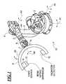
- FIG. 1in perspective view, shows a robot arm x-ray image acquisition system suitable for use in accordance with the inventive method system.
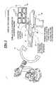
- FIG. 2illustrates the basic structural components of a system constructed and operating in accordance with the present invention.
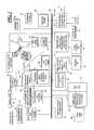
- FIG. 3is a detailed block diagram of an exemplary embodiment of the system of FIG. 2 .
- a robot arm x-ray image acquisition system 13is shown in FIG. 1 of the type described in DE 10 2005 012 700 A1, for purposes other than implementing minimally invasive procedures involving heart valves.
- the robotic portion of the device 13is mounted to a base 1 which, in this embodiment, is shown as a base affixable to the floor of a room in which the device 13 is used.
- the device 13may also be wall-mounted or sealing-mounted.
- a shoulder articulation 2is rotatably mounted on the base 1 , so as to be rotatable around a substantially vertical axis A 1 .
- the shoulder articulationis connected to a first arm portion 3 of an arm articulation, so that the first arm portion 3 is rotatable around a substantially horizontal axis A 2 .
- the first arm portion 3is connected via an elbow articulation 4 to a second arm portion 5 .
- the first arm portion 3 and the second arm portion 5are rotatable relative to each other around a substantially horizontal axis A 3 of the elbow articulation 4 .
- the second arm portion 5carries a wrist articulation 6 , which is rotatable relative to the second arm portion 5 around an axis A 4 .
- the wrist articulation 6also includes a further articulation joint connected to a mount 7 for, in this embodiment, a C-arm 11 .
- the holder 7 and the C-arm 11 connected theretoare rotatable around an articulation axis A 5 in the wrist articulation 6 , and the holder 7 and the C-arm 11 are also rotatable around a further articulation axis A 6 .
- the C-arm 11includes a curved support 8 , to which an x-ray source 9 and a radiation detector 12 are mounted for co-rotation with the support arm 8 .
- a beam gating diaphragm 10is disposed in front of the x-ray source 9 , so as to be in the path of an x-ray beam that is emitted from the x-ray source 10 that propagates to the radiation detector 12 .
- a beam gating diaphragmcould be placed in proximity to the radiation detector 12 .
- the robotic imaging device 13is usable in combination with a table support 14 for a patient 15 . Because of the numerous degrees of freedom provided by the robotic arm imaging device 13 , and the non-restrictive access that is associated therewith, the system shown in FIG. 2 is suitable for implementing the various types of minimally-invasive procedures involving heart valves that were initially described. Many of these procedures require implementation of a catheter 17 , which in the inventive system can be automatically or semi-automatically operated by a catheter control robot 16 .
- a bank 18 of monitors or displaysis provided that includes displays for separately displaying conventional types of images that are used in the aforementioned procedures.
- these displaysinclude a display for fused images 19 and a display for ultrasonic or catheter imaging 20 .
- One or more of the displays in the bank 18can display a three-dimensional image that is generated from multiple projections of the region of interest of the patient 15 acquired by the robotic image acquisition system 13 .
- the systemcan be provided with a plug & play ultrasonic or catheter interface 21 , if an ultrasound catheter is used.
- the systemcan also be provided with a patient-proximal control unit 22 , for operating the x-ray system, the ultrasound system and the catheter system from a single location.
- FIG. 3A more detailed block diagram presentation of the system of FIG. 2 is shown in FIG. 3 . All components are connected to a data bus 23 , which serves for transferring data as well as control instructions, as needed, between and among the various components.
- These componentsinclude an image processing unit 24 for processing images obtained with an imaging catheter, such as an IVUS catheter or an optical catheter.
- an image processing unit 25for a tracking sensor that is associated with the image catheter, or another interventional instrument.
- an image processing unit 26 for x-ray imageswhich includes a soft tissue processor, for generating images wherein soft tissue is accurately displayed.
- an image fusion unit 27Also connected to the data bus 23 is an image fusion unit 27 connected to the aforementioned display for fused images 19 .
- the data bus 23is also in communication with a DICOM interface 30 for patient data, such as obtained from and transmitted to a hospital information system HIS, and for receiving and transmitting images such as CT exposures and/or MR exposures.
- patient datasuch as obtained from and transmitted to a hospital information system HIS
- imagessuch as CT exposures and/or MR exposures.
- the image fusion 27is capable of performing functions such as image segmentation, auto-segmentation, image registration and image reconstruction based on data supplied thereto, such as from the robotic imaging device 13 or from archived images received via the DICOM interface 30 .
- the image fusion unitis connected to an image correction unit 28 which is, in turn connected to a calibration unit 29 , the latter also being in direct communication with the data bus 23 .
- An image data storage 44is also connected to the data bus 23 , for storing any images generated during the minimally-invasive procedure involving heart valves, and for supplying images for display during that procedure, that have been previously obtained and stored.
- Each of the image processing units 24 , 25 , 26 , and the image fusion unit 27 , and the image data storage 44communicate with the display bank 18 (shown in FIG. 2 ) via the data bus 30 .
- a user I/o unit 47is also in communication with other components via the data bus 30 .
- All units requiring power for operation thereofare supplied by a power supply unit 48 .
- FIG. 3Other components that will be most likely physically present in the operating room are shown above the data bus 23 in FIG. 3 .
- theseinclude a high-voltage generator 41 that supplies the necessary voltages and currents to the x-ray source 9 , under the control of a system controller 40 , which also operates the patient table 14 .
- a preprocessing unit 39 for processing the x-ray image data obtained from the radiation detector 12is in direct or wireless communication with the radiation detector 12 .
- a physiological signal processor 37is provided for monitoring functions such as ECG, respiration, body temperature, blood oxygen concentration, etc.
- This processor 37has an interface 38 for connection to appropriate physiological sensors.
- a preprocessing unit 34 for processing image data from the imaging catheteris also connected to the data bus 23 , which has a signal interface 35 for the tracking sensor of the catheter or other instruments.
- FIG. 3also shows a further preprocessing unit 31 for the imaging catheter, having a signal interface 32 , and connections 33 to the imaging catheter.
- the systemmay also be provided with an ablation device 36 , which is connected to the data bus 23 so that it can be operated by the system controller 40 .
- ablation device 36which is connected to the data bus 23 so that it can be operated by the system controller 40 .
- defibrillator/pacemaker 45a defibrillator/pacemaker 45 .
- An extracorporeal ultrasound system 42may also be provided, in the form of a 2D ultrasound system or a 3D color Doppler system, also connected to the data bus 23 so that it can be communicate with the image fusion unit 27 .
- a receiver/transmitter 43is provided that can operate electromagnetically or according to any other known tracking mode.
- An anesthesia ventilator 46can also be provided with appropriate user interfaces and interfaces to the patient. Since such a unit is typically a stand-alone unit operated by an anesthesiologist, it is not shown as being connected to the data bus 23 , although such a connection is possible, if desired.
Landscapes
- Health & Medical Sciences (AREA)
- Life Sciences & Earth Sciences (AREA)
- Engineering & Computer Science (AREA)
- Medical Informatics (AREA)
- Surgery (AREA)
- Animal Behavior & Ethology (AREA)
- Public Health (AREA)
- Heart & Thoracic Surgery (AREA)
- Veterinary Medicine (AREA)
- Molecular Biology (AREA)
- Biomedical Technology (AREA)
- General Health & Medical Sciences (AREA)
- Nuclear Medicine, Radiotherapy & Molecular Imaging (AREA)
- Pathology (AREA)
- Physics & Mathematics (AREA)
- Biophysics (AREA)
- Robotics (AREA)
- Radiology & Medical Imaging (AREA)
- Optics & Photonics (AREA)
- High Energy & Nuclear Physics (AREA)
- Oral & Maxillofacial Surgery (AREA)
- Dentistry (AREA)
- Cardiology (AREA)
- Physiology (AREA)
- Anesthesiology (AREA)
- Immunology (AREA)
- Vascular Medicine (AREA)
- Automation & Control Theory (AREA)
- Mechanical Engineering (AREA)
- Apparatus For Radiation Diagnosis (AREA)
- Ultra Sonic Daignosis Equipment (AREA)
- Surgical Instruments (AREA)
Abstract
Description
Claims (19)
Priority Applications (3)
| Application Number | Priority Date | Filing Date | Title |
|---|---|---|---|
| US12/046,727US8792964B2 (en) | 2008-03-12 | 2008-03-12 | Method and apparatus for conducting an interventional procedure involving heart valves using a robot-based X-ray device |
| CN200910126239ACN101530338A (en) | 2008-03-12 | 2009-03-09 | Method and apparatus for conducting an interventional procedure involving heart valves using a robot-based x-ray device |
| JP2009058522AJP2009213892A (en) | 2008-03-12 | 2009-03-11 | Method and apparatus for conducting an interventional procedure involving heart valves |
Applications Claiming Priority (1)
| Application Number | Priority Date | Filing Date | Title |
|---|---|---|---|
| US12/046,727US8792964B2 (en) | 2008-03-12 | 2008-03-12 | Method and apparatus for conducting an interventional procedure involving heart valves using a robot-based X-ray device |
Publications (2)
| Publication Number | Publication Date |
|---|---|
| US20090234444A1 US20090234444A1 (en) | 2009-09-17 |
| US8792964B2true US8792964B2 (en) | 2014-07-29 |
Family
ID=41063896
Family Applications (1)
| Application Number | Title | Priority Date | Filing Date |
|---|---|---|---|
| US12/046,727Active2032-10-31US8792964B2 (en) | 2008-03-12 | 2008-03-12 | Method and apparatus for conducting an interventional procedure involving heart valves using a robot-based X-ray device |
Country Status (3)
| Country | Link |
|---|---|
| US (1) | US8792964B2 (en) |
| JP (1) | JP2009213892A (en) |
| CN (1) | CN101530338A (en) |
Cited By (5)
| Publication number | Priority date | Publication date | Assignee | Title |
|---|---|---|---|---|
| WO2021086950A1 (en)* | 2019-10-28 | 2021-05-06 | Khadivi Bahram | Systems and methods for deploying transcatheter heart valves |
| USD935609S1 (en) | 2019-11-19 | 2021-11-09 | Siemens Healthcare Gmbh | Robotic catheter manipulator |
| US11213273B2 (en) | 2012-12-03 | 2022-01-04 | Koninklijke Philips N.V. | Integration of ultrasound and x-ray modalities |
| US20230078240A1 (en)* | 2022-08-02 | 2023-03-16 | BEIJING WEMED MEDICAL EQUIPMENT Co.,Ltd. | Interventional unmanned operation chanmber system |
| US20230278217A1 (en)* | 2022-03-01 | 2023-09-07 | Alcon Inc. | Robotic imaging system with force-based collision avoidance mode |
Families Citing this family (36)
| Publication number | Priority date | Publication date | Assignee | Title |
|---|---|---|---|---|
| US9517106B2 (en) | 1999-09-17 | 2016-12-13 | Intuitive Surgical Operations, Inc. | Systems and methods for commanded reconfiguration of a surgical manipulator using the null-space |
| US8004229B2 (en) | 2005-05-19 | 2011-08-23 | Intuitive Surgical Operations, Inc. | Software center and highly configurable robotic systems for surgery and other uses |
| US9043018B2 (en)* | 2007-12-27 | 2015-05-26 | Intuitive Surgical Operations, Inc. | Medical device with orientable tip for robotically directed laser cutting and biomaterial application |
| DE102011077753B4 (en)* | 2011-06-17 | 2020-06-10 | Siemens Healthcare Gmbh | Device for planning a transcatheter aortic valve implantation |
| JP5011455B1 (en)* | 2011-06-30 | 2012-08-29 | 医療法人社団神▲崎▼循環器クリニック | X-ray diagnostic equipment |
| WO2013063674A1 (en) | 2011-11-04 | 2013-05-10 | Titan Medical Inc. | Apparatus and method for controlling an end-effector assembly |
| EP2785267B1 (en)* | 2011-11-30 | 2022-01-12 | Titan Medical Inc. | Apparatus and method for supporting a robotic arm |
| EP2854687B1 (en) | 2012-06-01 | 2022-08-24 | Intuitive Surgical Operations, Inc. | Systems for avoiding collisions between manipulator arms using a null-space |
| CN104334109B (en) | 2012-06-01 | 2017-06-23 | 直观外科手术操作公司 | Systems and methods for reconfiguration of commands of a surgical manipulator using null space |
| CN107595392B (en) | 2012-06-01 | 2020-11-27 | 直观外科手术操作公司 | Avoidance of manipulator arm collisions with patient using null space |
| CN104411248B (en)* | 2012-06-28 | 2017-09-26 | 皇家飞利浦有限公司 | It is used for the C-arm trajectory planning that optimized image is gathered in endo-surgical |
| CN105188590B (en) | 2012-12-10 | 2019-04-26 | 直观外科手术操作公司 | Collision avoidance during controlled movement of an image capture device and an actuatable device movable arm |
| CN104853680B (en) | 2012-12-11 | 2018-04-10 | 皇家飞利浦有限公司 | The Spatial Dimension of Spatial Dimension for determining the object component in object determines equipment |
| WO2014091380A1 (en)* | 2012-12-13 | 2014-06-19 | Koninklijke Philips N.V. | Interventional system |
| US10028788B2 (en) | 2012-12-31 | 2018-07-24 | Mako Surgical Corp. | System for image-based robotic surgery |
| US9943958B2 (en)* | 2013-03-15 | 2018-04-17 | Corindus, Inc. | System and method for controlling a position of an articulated robotic arm |
| US10864629B2 (en) | 2013-03-15 | 2020-12-15 | Corindus, Inc. | System and method for controlling a position of an articulated robotic arm |
| US9691966B2 (en) | 2013-11-11 | 2017-06-27 | Siemens Aktiengesellschaft | Surface-mounted collision sensor, and method for collision detection |
| CN104873211A (en)* | 2014-02-27 | 2015-09-02 | 上海联影医疗科技有限公司 | Image positioning system and linear accelerator system |
| US9208559B1 (en) | 2014-07-25 | 2015-12-08 | Siemens Aktiengesellschaft | Method and apparatus for gastric artery chemical embolization |
| JP6511238B2 (en)* | 2014-09-08 | 2019-05-15 | ミズホ株式会社 | Operating table |
| EP3261545B1 (en)* | 2015-02-27 | 2019-12-11 | Siemens Aktiengesellschaft | Robust calcification tracking in fluoroscopic imaging |
| KR102055313B1 (en)* | 2015-06-29 | 2019-12-12 | 카와사키 주코교 카부시키 카이샤 | Robotic systems |
| CN105078581A (en)* | 2015-09-07 | 2015-11-25 | 四川大学 | Mobile robot-assisted surgical system having positioning function |
| US10034716B2 (en)* | 2015-09-14 | 2018-07-31 | Globus Medical, Inc. | Surgical robotic systems and methods thereof |
| CN105496562A (en)* | 2015-12-10 | 2016-04-20 | 杜茂芳 | Anesthesia nursing device for operating room |
| DE102016209389A1 (en)* | 2016-05-31 | 2017-11-30 | Siemens Healthcare Gmbh | Arrangement for monitoring a positioning of a heart valve prosthesis and corresponding method |
| EP3515288B1 (en)* | 2016-09-23 | 2021-06-23 | Koninklijke Philips N.V. | Visualization of an image object relating to an instrument in an extracorporeal image |
| EP3409230B1 (en) | 2017-05-31 | 2019-05-22 | Siemens Healthcare GmbH | Movement of a robot arm |
| EP3709885B1 (en)* | 2017-11-13 | 2024-06-12 | Koninklijke Philips N.V. | Autonomous x-ray control for robotic navigation |
| KR102051429B1 (en)* | 2017-12-27 | 2019-12-03 | 주식회사 매경 | Mattress with cold and warm air for bedsore prevention |
| CA3092259A1 (en)* | 2018-02-28 | 2019-09-06 | Live Vue Technologies Inc. | Apparatus and method for in vivo imaging of soft and hard tissue interfaces |
| CN110448378B (en)* | 2019-08-13 | 2021-03-02 | 北京唯迈医疗设备有限公司 | Immersive intervention operation integrated console |
| JP7412259B2 (en) | 2020-04-10 | 2024-01-12 | 川崎重工業株式会社 | Medical support robots and medical robot systems |
| CN111493912B (en)* | 2020-06-02 | 2021-05-04 | 广东中科天机医疗装备有限公司 | DR robot system and operation steps using same |
| CN117944070B (en)* | 2024-03-26 | 2024-06-04 | 首都医科大学附属北京同仁医院 | A medical robotic arm for thyroid monitoring |
Citations (19)
| Publication number | Priority date | Publication date | Assignee | Title |
|---|---|---|---|---|
| US4819751A (en) | 1987-10-16 | 1989-04-11 | Baxter Travenol Laboratories, Inc. | Valvuloplasty catheter and method |
| US5042486A (en) | 1989-09-29 | 1991-08-27 | Siemens Aktiengesellschaft | Catheter locatable with non-ionizing field and method for locating same |
| US5345940A (en) | 1991-11-08 | 1994-09-13 | Mayo Foundation For Medical Education And Research | Transvascular ultrasound hemodynamic and interventional catheter and method |
| US6059731A (en) | 1998-08-19 | 2000-05-09 | Mayo Foundation For Medical Education And Research | Simultaneous side-and-end viewing underfluid catheter |
| US20010005410A1 (en)* | 1999-12-07 | 2001-06-28 | Volker Rasche | X-ray device provided with a robot arm |
| US6298261B1 (en) | 1997-11-15 | 2001-10-02 | Roke Manor Research Limited | Catheter tracking system |
| US20020045817A1 (en)* | 2000-10-17 | 2002-04-18 | Masahide Ichihashi | Radiographic image diagnosis apparatus |
| WO2004103223A1 (en) | 2003-05-20 | 2004-12-02 | The Cleveland Clinic Foundation | Apparatus and methods for repair of a cardiac valve |
| US20050161051A1 (en)* | 2003-01-08 | 2005-07-28 | Cyberheart, Inc. | System for non-invasive heart treatment |
| US20060074485A1 (en) | 2004-05-17 | 2006-04-06 | Fidel Realyvasquez | Method and apparatus for percutaneous valve repair |
| US20060120507A1 (en) | 2004-11-26 | 2006-06-08 | Thomas Brunner | Angiographic x-ray diagnostic device for rotation angiography |
| US7087023B2 (en) | 2003-02-14 | 2006-08-08 | Sensant Corporation | Microfabricated ultrasonic transducers with bias polarity beam profile control and method of operating the same |
| US20070016108A1 (en)* | 2005-07-14 | 2007-01-18 | Siemens Aktiengesellschaft | Method for 3D visualization of vascular inserts in the human body using the C-arm |
| US20070027390A1 (en)* | 2005-07-13 | 2007-02-01 | Michael Maschke | System for performing and monitoring minimally invasive interventions |
| US20070030945A1 (en) | 2005-04-08 | 2007-02-08 | Siemens Aktiengesellschaft | Operating method for X-ray equipment |
| US20070173861A1 (en)* | 2006-01-10 | 2007-07-26 | Mediguide Ltd. | System and method for positioning an artificial heart valve at the position of a malfunctioning valve of a heart through a percutaneous route |
| US20080218770A1 (en)* | 2007-02-02 | 2008-09-11 | Hansen Medical, Inc. | Robotic surgical instrument and methods using bragg fiber sensors |
| US20080243064A1 (en)* | 2007-02-15 | 2008-10-02 | Hansen Medical, Inc. | Support structure for robotic medical instrument |
| US20080240363A1 (en) | 2005-03-18 | 2008-10-02 | Siemens Aktiengesellschaft | X-ray device |
Family Cites Families (10)
| Publication number | Priority date | Publication date | Assignee | Title |
|---|---|---|---|---|
| JP2907963B2 (en)* | 1990-06-21 | 1999-06-21 | 株式会社東芝 | Magnetic resonance monitoring therapy device |
| US6298731B1 (en)* | 1999-08-18 | 2001-10-09 | Fasco Controls Corporation | Combination pressure sensor and regulator for direct injection engine fuel system |
| DE10003524B4 (en)* | 2000-01-27 | 2006-07-13 | Siemens Ag | Mobile X-ray device and method for the determination of projection geometries |
| FR2847797B1 (en)* | 2002-11-28 | 2005-09-23 | Ge Med Sys Global Tech Co Llc | IMPROVEMENTS IN FLUOROSCOPIC IMAGING METHODS AND DEVICES |
| EP1673131B1 (en)* | 2003-07-17 | 2010-03-10 | Cordis Corporation | Devices for percutaneously treating aortic valve stenosis |
| WO2005087128A1 (en)* | 2004-03-05 | 2005-09-22 | Hansen Medical, Inc. | Robotic catheter system |
| DE102005045071A1 (en)* | 2005-09-21 | 2007-04-12 | Siemens Ag | Catheter device with a position sensor system for the treatment of a partial and / or complete vascular occlusion under image monitoring |
| DE102005030609A1 (en)* | 2005-06-30 | 2007-01-04 | Siemens Ag | Method or X-ray device for creating a series recording of medical X-ray images of a possibly moving patient during the series recording |
| EP1986563B1 (en)* | 2006-02-22 | 2012-12-26 | Hansen Medical, Inc. | System and apparatus for measuring distal forces on a working instrument |
| WO2007146864A2 (en)* | 2006-06-13 | 2007-12-21 | Rhythmia Medical, Inc. | Non-contact cardiac mapping, including moving catheter and multi-beat integration |
- 2008
- 2008-03-12USUS12/046,727patent/US8792964B2/enactiveActive
- 2009
- 2009-03-09CNCN200910126239Apatent/CN101530338A/enactivePending
- 2009-03-11JPJP2009058522Apatent/JP2009213892A/enactivePending
Patent Citations (19)
| Publication number | Priority date | Publication date | Assignee | Title |
|---|---|---|---|---|
| US4819751A (en) | 1987-10-16 | 1989-04-11 | Baxter Travenol Laboratories, Inc. | Valvuloplasty catheter and method |
| US5042486A (en) | 1989-09-29 | 1991-08-27 | Siemens Aktiengesellschaft | Catheter locatable with non-ionizing field and method for locating same |
| US5345940A (en) | 1991-11-08 | 1994-09-13 | Mayo Foundation For Medical Education And Research | Transvascular ultrasound hemodynamic and interventional catheter and method |
| US6298261B1 (en) | 1997-11-15 | 2001-10-02 | Roke Manor Research Limited | Catheter tracking system |
| US6059731A (en) | 1998-08-19 | 2000-05-09 | Mayo Foundation For Medical Education And Research | Simultaneous side-and-end viewing underfluid catheter |
| US20010005410A1 (en)* | 1999-12-07 | 2001-06-28 | Volker Rasche | X-ray device provided with a robot arm |
| US20020045817A1 (en)* | 2000-10-17 | 2002-04-18 | Masahide Ichihashi | Radiographic image diagnosis apparatus |
| US20050161051A1 (en)* | 2003-01-08 | 2005-07-28 | Cyberheart, Inc. | System for non-invasive heart treatment |
| US7087023B2 (en) | 2003-02-14 | 2006-08-08 | Sensant Corporation | Microfabricated ultrasonic transducers with bias polarity beam profile control and method of operating the same |
| WO2004103223A1 (en) | 2003-05-20 | 2004-12-02 | The Cleveland Clinic Foundation | Apparatus and methods for repair of a cardiac valve |
| US20060074485A1 (en) | 2004-05-17 | 2006-04-06 | Fidel Realyvasquez | Method and apparatus for percutaneous valve repair |
| US20060120507A1 (en) | 2004-11-26 | 2006-06-08 | Thomas Brunner | Angiographic x-ray diagnostic device for rotation angiography |
| US20080240363A1 (en) | 2005-03-18 | 2008-10-02 | Siemens Aktiengesellschaft | X-ray device |
| US20070030945A1 (en) | 2005-04-08 | 2007-02-08 | Siemens Aktiengesellschaft | Operating method for X-ray equipment |
| US20070027390A1 (en)* | 2005-07-13 | 2007-02-01 | Michael Maschke | System for performing and monitoring minimally invasive interventions |
| US20070016108A1 (en)* | 2005-07-14 | 2007-01-18 | Siemens Aktiengesellschaft | Method for 3D visualization of vascular inserts in the human body using the C-arm |
| US20070173861A1 (en)* | 2006-01-10 | 2007-07-26 | Mediguide Ltd. | System and method for positioning an artificial heart valve at the position of a malfunctioning valve of a heart through a percutaneous route |
| US20080218770A1 (en)* | 2007-02-02 | 2008-09-11 | Hansen Medical, Inc. | Robotic surgical instrument and methods using bragg fiber sensors |
| US20080243064A1 (en)* | 2007-02-15 | 2008-10-02 | Hansen Medical, Inc. | Support structure for robotic medical instrument |
Non-Patent Citations (5)
| Title |
|---|
| "Percutaneous Valve Repair: Update on Mitral Regurgitation and Endovascular Approaches to the Mitral Valve," Dieter, Applications in Imaging-Cardiac Interventions (2003) pp. 11-14. |
| "Percutaneous Valve Repair: Update on Mitral Regurgitation and Endovascular Approaches to the Mitral Valve," Dieter, Applications in Imaging—Cardiac Interventions (2003) pp. 11-14. |
| "Percutaneous Valve Therapies: Where We Are and Where We Are Going," Feldman, Complex Coronary Intervention (2006). |
| "Realization of Silicon Based Ultrasound Micro-Systems," Diss. ETH No. 13202-A Dissertation Submitted to the Swiss Federal Institute of Technology-Zurich-1999-Presented by Christoph Kuratli. |
| "Realization of Silicon Based Ultrasound Micro-Systems," Diss. ETH No. 13202—A Dissertation Submitted to the Swiss Federal Institute of Technology—Zurich—1999—Presented by Christoph Kuratli. |
Cited By (6)
| Publication number | Priority date | Publication date | Assignee | Title |
|---|---|---|---|---|
| US11213273B2 (en) | 2012-12-03 | 2022-01-04 | Koninklijke Philips N.V. | Integration of ultrasound and x-ray modalities |
| WO2021086950A1 (en)* | 2019-10-28 | 2021-05-06 | Khadivi Bahram | Systems and methods for deploying transcatheter heart valves |
| USD935609S1 (en) | 2019-11-19 | 2021-11-09 | Siemens Healthcare Gmbh | Robotic catheter manipulator |
| US20230278217A1 (en)* | 2022-03-01 | 2023-09-07 | Alcon Inc. | Robotic imaging system with force-based collision avoidance mode |
| US12390930B2 (en)* | 2022-03-01 | 2025-08-19 | Alcon Inc. | Robotic imaging system with force-based collision avoidance mode |
| US20230078240A1 (en)* | 2022-08-02 | 2023-03-16 | BEIJING WEMED MEDICAL EQUIPMENT Co.,Ltd. | Interventional unmanned operation chanmber system |
Also Published As
| Publication number | Publication date |
|---|---|
| US20090234444A1 (en) | 2009-09-17 |
| JP2009213892A (en) | 2009-09-24 |
| CN101530338A (en) | 2009-09-16 |
Similar Documents
| Publication | Publication Date | Title |
|---|---|---|
| US8792964B2 (en) | Method and apparatus for conducting an interventional procedure involving heart valves using a robot-based X-ray device | |
| US8252049B2 (en) | Method for therapy of heart valves with a robot-based X-ray device | |
| US20230248942A1 (en) | Systems and methods for 3d stereoscopic angiovision, angionavigation and angiotherapeutics | |
| CN116725669B (en) | System and computer readable storage medium for facilitating navigation of anatomical endoluminal networks | |
| US10010373B2 (en) | Navigation system for cardiac therapies using gating | |
| Shi et al. | Three-dimensional intravascular reconstruction techniques based on intravascular ultrasound: A technical review | |
| JP5797763B2 (en) | Gated image acquisition and patient model structure | |
| JP5294545B2 (en) | Medical system for inserting a catheter into a vessel | |
| US10524865B2 (en) | Combination of 3D ultrasound and computed tomography for guidance in interventional medical procedures | |
| JP7049325B6 (en) | Visualization of image objects related to instruments in in-vitro images | |
| US20100022873A1 (en) | Navigation System for Cardiac Therapies | |
| US20070233238A1 (en) | Devices for Imaging and Navigation During Minimally Invasive Non-Bypass Cardiac Procedures | |
| US20080247506A1 (en) | System for carrying out and monitoring minimally-invasive interventions | |
| JP2015155048A (en) | Heart treatment kit, system, and method for radiosurgically alleviating arhythmia | |
| JP2010155098A (en) | Method and system to align medical information relating to first coordinate system in second coordinate system using mps system | |
| JP2009532127A (en) | Nested catheter with electromagnetic coil for imaging and navigation during cardiac procedures | |
| CN102319117A (en) | Large-vessel interventional device implantation system based on magnetic navigation fusion of real-time ultrasound information | |
| US20090306500A1 (en) | Workflow for minimally invasive heart treatment | |
| US8177835B2 (en) | Method of imaging for heart valve implant procedure | |
| JP2023512203A (en) | Real-Time Fusion Holographic Visualization and Guidance for Deployment of Structural Heart Repair or Replacement Products | |
| Li et al. | Advances of surgical robotics: image-guided classification and application | |
| JP6445593B2 (en) | Control of X-ray system operation and image acquisition for 3D / 4D aligned rendering of the targeted anatomy | |
| Lang | Candles to computers: the story of minimally invasive procedures | |
| Ovcharenko et al. | Visual and robotic guidance systems for transcatheter implantation of heart value prostheses |
Legal Events
| Date | Code | Title | Description |
|---|---|---|---|
| AS | Assignment | Owner name:SIEMENS AKTIENGESELLSCHAFT, GERMANY Free format text:ASSIGNMENT OF ASSIGNORS INTEREST;ASSIGNOR:MASCHKE, MICHAEL;REEL/FRAME:020640/0195 Effective date:20071019 | |
| STCF | Information on status: patent grant | Free format text:PATENTED CASE | |
| AS | Assignment | Owner name:SIEMENS HEALTHCARE GMBH, GERMANY Free format text:ASSIGNMENT OF ASSIGNORS INTEREST;ASSIGNOR:SIEMENS AKTIENGESELLSCHAFT;REEL/FRAME:039271/0561 Effective date:20160610 | |
| MAFP | Maintenance fee payment | Free format text:PAYMENT OF MAINTENANCE FEE, 4TH YEAR, LARGE ENTITY (ORIGINAL EVENT CODE: M1551) Year of fee payment:4 | |
| MAFP | Maintenance fee payment | Free format text:PAYMENT OF MAINTENANCE FEE, 8TH YEAR, LARGE ENTITY (ORIGINAL EVENT CODE: M1552); ENTITY STATUS OF PATENT OWNER: LARGE ENTITY Year of fee payment:8 | |
| AS | Assignment | Owner name:SIEMENS HEALTHINEERS AG, GERMANY Free format text:ASSIGNMENT OF ASSIGNORS INTEREST;ASSIGNOR:SIEMENS HEALTHCARE GMBH;REEL/FRAME:066088/0256 Effective date:20231219 | |
| AS | Assignment | Owner name:SIEMENS HEALTHINEERS AG, GERMANY Free format text:CORRECTIVE ASSIGNMENT TO CORRECT THE ASSIGNEE PREVIOUSLY RECORDED AT REEL: 066088 FRAME: 0256. ASSIGNOR(S) HEREBY CONFIRMS THE ASSIGNMENT;ASSIGNOR:SIEMENS HEALTHCARE GMBH;REEL/FRAME:071178/0246 Effective date:20231219 |