US8792699B2 - Motion tracking for clinical parameter derivation and adaptive flow acquisition in magnetic resonance imaging - Google Patents
Motion tracking for clinical parameter derivation and adaptive flow acquisition in magnetic resonance imagingDownload PDFInfo
- Publication number
- US8792699B2 US8792699B2US13/239,530US201113239530AUS8792699B2US 8792699 B2US8792699 B2US 8792699B2US 201113239530 AUS201113239530 AUS 201113239530AUS 8792699 B2US8792699 B2US 8792699B2
- Authority
- US
- United States
- Prior art keywords
- landmarks
- images
- sequence
- plane
- propagation
- Prior art date
- Legal status (The legal status is an assumption and is not a legal conclusion. Google has not performed a legal analysis and makes no representation as to the accuracy of the status listed.)
- Active, expires
Links
Images


Classifications
- G—PHYSICS
- G01—MEASURING; TESTING
- G01R—MEASURING ELECTRIC VARIABLES; MEASURING MAGNETIC VARIABLES
- G01R33/00—Arrangements or instruments for measuring magnetic variables
- G01R33/20—Arrangements or instruments for measuring magnetic variables involving magnetic resonance
- G01R33/44—Arrangements or instruments for measuring magnetic variables involving magnetic resonance using nuclear magnetic resonance [NMR]
- G01R33/48—NMR imaging systems
- G01R33/54—Signal processing systems, e.g. using pulse sequences ; Generation or control of pulse sequences; Operator console
- G01R33/56—Image enhancement or correction, e.g. subtraction or averaging techniques, e.g. improvement of signal-to-noise ratio and resolution
- G01R33/563—Image enhancement or correction, e.g. subtraction or averaging techniques, e.g. improvement of signal-to-noise ratio and resolution of moving material, e.g. flow contrast angiography
- G01R33/56308—Characterization of motion or flow; Dynamic imaging
- G01R33/56316—Characterization of motion or flow; Dynamic imaging involving phase contrast techniques
Definitions
- the present disclosurerelates to magnetic resonance imaging (MRI) and, more specifically, to motion tracking for clinical parameter derivation and adaptive flow acquisition in MRI.
- MRImagnetic resonance imaging
- Magnetic resonance angiographyis a field of medical imaging that uses magnetic resonance imaging (MRI) to study blood vessels.
- MRAMagnetic resonance angiography
- phase-contrast flow acquisitionalso known as phase-contrast MRA.
- phase-contrast flow acquisitionthe flow of blood through vessels may be imaged and analyzed to provide imagery and to quantify various parameters such as the speed of blood flow.
- the resulting imagery and quantified parametersmay have significant diagnostic value and may facilitate life-saving intervention.
- a method for performing flow acquisition within a sequence of magnetic resonance imagesincludes commencing an acquisition of a sequence of images.
- One or more landmarksare automatically detected from within one or more images of the sequence of images.
- the detected one or more landmarksare propagated across subsequent images of the sequence of images.
- An image acquisition planeis fitted to the propagation of landmarks.
- One or more flow propertiesare determined from the sequence of images within the fitted image acquisition plane.
- a method for determining tissue velocities within a sequence of magnetic resonance imagesincludes commencing an acquisition of a sequence of images.
- One or more landmarksare automatically detected from within one or more images of the sequence of images.
- the detected one or more landmarksare propagated across subsequent images of the sequence of images.
- An image acquisition planeis fitted to the propagation of landmarks.
- One or more tissue velocitiesare determined from the sequence of images within the fitted image acquisition plane.
- Determining one or more tissue velocitiesmay include determining one or more clinical parameters. Additionally, or alternatively, determining one or more tissue velocities includes determining an S′ velocity, an A′ velocity, or an E′ velocity.
- the sequence of imagesmay include a sequence of magnetic resonance (MR) image frames.
- the one or more landmarksmay include a point of the mitral valve, a point of the tricuspid valve, or a point of the aortic valve.
- the detection of the landmarksmay be performed in conjunction with detection of one or more apex points of the myocardium and the detection of the apex points may be used to bolster the detection of the valve points by providing additional anchoring points.
- the detected one or more landmarksmay be propagated over all phases of a cardiac cycle.
- the propagation of the one or more landmarksmay include transforming a landmark from a starting phase to another phase using deformation fields.
- the deformation fieldsmay be computed using an inverse-consistent deformable registration algorithm.
- Determining the one or more flow propertiesmay include determining a mitral valve annulus velocity. Determining the one or more flow properties may include determining a velocity of each landmark computed from the propagated movement of the landmark from one phase to another within the image acquisition plane. Determining the one or more flow properties may include determining an S′ velocity, an A′ velocity, or an E′ velocity.
- the one or more landmarksmay include a mitral valve insertion point and an extent of a left ventricle may be derived from the propagated location of the mitral valve insertion point.
- Propagating the detected one or more landmarksmay include modeling or forecasting where each of the landmarks are likely to be found based on where they have been most recently and at other occasions at a similar point within the cardiac cycle.
- Fitting the image acquisition plane to the propagation of landmarksmay include finding a plane that minimizes an orthogonal distance between the landmarks and the plane and occupies a point that is calculated to be the center of all landmarks taken together.
- a system for performing flow acquisition within a sequence of magnetic resonance imagesincludes a medical imaging device for commencing an acquisition of a sequence of images.
- An image processing deviceincludes a landmark detection module, a propagation module, and a structure fitting module.
- the landmark detection moduleautomatically detects one or more landmarks from within one or more images of the sequence of images.
- the propagation modulepropagates the detected one or more landmarks across subsequent images of the sequence of images.
- the structure fitting modulefits a geometric plane to the propagation of landmarks.
- a method for deriving mitral annulus velocity within a sequence of magnetic resonance imagesincludes commencing an acquisition of a sequence of images, automatically detecting one or more mitral valve insertion points, propagating the detected mitral valve insertion points across subsequent images of the sequence of images, fitting a plane to the propagation of valve insertion points, and determining a velocity of the mitral annulus from the sequence of images within the fitted plane.
- the methodmay additionally include determining an extent of a left ventricle from the determined velocity of the mitral annulus.
- Fitting the valve plane to the propagation of the mitral valve insertion pointsmay include finding a plane that minimizes an orthogonal distance between the mitral valve insertion points and the plane and occupies a point that is calculated to be the center of all mitral valve insertion points taken together.
- the detection of the mitral valve insertion pointsmay be performed in conjunction with detection of one or more apex points of the myocardium and the detection of the apex points may be used to bolster the detection of the mitral valve insertion points by providing additional anchoring points.
- Propagation of the one or more mitral valve insertion pointsmay include transforming the mitral valve insertion points from a starting phase to another phase using deformation fields that are computed using an inverse-consistent deformable registration algorithm.
- a method for determining clinical parameters within a sequence of imagesincludes commencing an acquisition of a sequence of images, automatically detecting one or more landmarks from within one or more images of the sequence of images, propagating the detected one or more landmarks across subsequent images of the sequence of images, and determining one or more clinical parameters from the propagation of landmarks.
- FIG. 1is a flowchart illustrating an approach for performing phase-contrast flow acquisition within a medical image according to exemplary embodiments of the present invention
- FIG. 2is a flowchart illustrating an approach for determining mitral valve annulus velocity according to exemplary embodiments of the present invention
- FIG. 3is a chart illustrating mitral annulus velocity over trigger time according to an exemplary embodiment of the present invention
- FIG. 4is a diagram illustrating a relationship of the various modules according to exemplary embodiments of the present invention.
- FIG. 5shows an example of a computer system capable of implementing the method and apparatus according to embodiments of the present disclosure.
- Exemplary embodiments of the present inventionseek to provide phase-contrast flow acquisition for vessels and valves that may be subject to cardiac motion.
- Phase-contrast flow acquisitionmay be used to measure the frame-to-frame velocity of each pixel within a sequence of medical image frames.
- Phase-contrast acquisitionmay be performed directly at the location of the cardiac valves in order to determine and/or measure the flow velocity of blood through the valves.
- Phase-contrastmay be acquired as a 2D flow measurement by measuring the flow through individual pixels at the acquisition location. From this data, parameters such as average blood velocity, peak blood velocity, and peak blood flow through a blood vessel may be determined.
- the shunt flow, or the aortic or pulmonary regurgitationmay be determined. Accordingly, significant diagnostic value may be gleamed from phase-contrast flow acquisition.
- Phase-contrast flow acquisitionmay be particularly difficult to perform when used to analyze the flow characteristics of blood traveling through vessels and valves that are themselves subject to motion such as cardiac motion.
- cardiac motionthe valves may move up and down over time due to the beating of the heart. Therefore, if an acquisition plane of the medical imaging device remains fixed, the valves of interest may move in and out of the image plane and the flow measurement may become inaccurate.
- Exemplary embodiments of the present inventionprovide for a dynamic acquisition plane within cine acquisitions for performing phase-contrast flow acquisition.
- the motion of the image planemay be automatically tracked by automatically determining the position of the valves, for example, at the valve plane, for which phase-contrast flow acquisition is to be performed within. Then, the position of the valves over time may be tracked in long-axis images of the heart.
- the valve planemay be tracked in three-dimensions and its motion may be effectively modeled so that phase-contrast flow acquisition may be accurately performed even as the valve continues to move in accordance with the heartbeat.
- Exemplary embodiments of the present inventionmay utilize three core components.
- the first componentis landmark detection. It is here that key anatomical landmarks are identified within medial image data.
- the landmarks usedmay include cardiac valves.
- the second componentis propagation of landmarks. It is here that the location and movement of each of the detected landmarks are analyzed and expected motion predicted.
- the third componentis shape fitting. It is here that a geometric shape is fitted to the propagated landmarks.
- Exemplary embodiments of the present inventionmay utilize one or more of the above-described components to perform one or more of the following objectives.
- the first objectiveis flow acquisition.
- Flow acquisitionmay be performed by first detecting valves as landmarks within an image frame. Then, the valve landmarks may be propagated through subsequent image frames. Next, a geometric plane may be fitted to the propagated valve landmarks and its coordinates may then be used to determine the acquisition plane. Then, within the acquisition plane, the velocity of each pixel may be analyzed to determine various flow acquisition parameters.
- the second objectiveis mitral annulus velocity determination.
- Exemplary embodiments of the present inventionmay perform mitral annulus velocity determination by first detecting, within an image frame, the lateral and septal mitral valve insertion points as landmarks. Then, the insertion points may be propagated through subsequent image frames. Then, a 3D valve plane may be fitted to all propagated insertion points. The velocity of the tracked insertion points may then be determined based on the tracking of the valve planes.
- FIG. 1is a flowchart illustrating an approach for performing phase-contrast flow acquisition within a medical image according to exemplary embodiments of the present invention.
- acquisition of a cine medical imagemay be commenced (Step S 11 ).
- the cine medical imagemay be a set of several medical image frames acquired over time, for example, using an MRI, although exemplary embodiments of the present invention may be applied to other forms of medical imaging such as ultrasounds, fluoroscopic images, computed tomography (CT) images and the like.
- CTcomputed tomography
- Automatic landmark detectionmay then be used to automatically extract one or more landmarks from frames of the acquired medical image sequence (Step S 12 ).
- the landmarksmay include one or more valves or valve points. For example, the mitral valve may be used as the landmark.
- a suitable landmarkis the tricuspid valve.
- the aortic valvemay also be used as a suitable landmark. It should be understood that while cardiac valves are offered as examples of suitable landmarks, other anatomical structures may be used in accordance with exemplary embodiments of the present invention.
- the extracted landmarksmay be propagated over time over all phases of the cardiac cycle (Step S 13 ).
- Propagation of the extracted landmarksmay include determining the location of the landmarks in subsequent image frames based on the known location of the landmarks from a prior image frame.
- propagationmay include the transformation of a landmark or contour from one starting phase to other phases and/or frames using deformation fields that may be computed by an inverse-consistent deformable registration algorithm.
- Propagationmay be said to span all phases of the cardiac cycle when the one or more landmarks have been effectively located within image frames that span at least one full cardiac cycle, including systole and diastole periods.
- Propagation of the landmarksmay be performed geometrically. Accordingly, the propagated landmarks may be fitted to a high-dimensional structure, for example, a plane. Propagation may be two fold, first the deformation fields may be used and then, the landmark propagation may be further constrained by a geometric structure. The geometrically propagated, detected landmarks may be fitted to a high-dimensional structure as part of the image sequence. By doing so, the geometric consistency may be provided by the propagation function and outliers may be treated or prevented by the fitting.
- One such geometrical objectmay be a plane that may then be fitted to the cine medical image frames based on the locations of the propagated landmarks (Step S 14 ).
- the planemay be fitted to multiple long axis slices of the medical image such as those that cross the locations of the propagated landmarks.
- the planemay include the mitral valve plane.
- the planemay include the tricuspid valve plane as imaged in the 4-chamber long axis view of the heart.
- the planemay include the aortic valve as imaged by 3-chamber long axis images or left ventricular outflow tract (LVOT) images.
- LVOTleft ventricular outflow tract
- Phase-contrast flow acquisitionmay then be performed within the fitted plane that may be translated to a format understood by the phase-contrast acquisition algorithm (Step S 15 ).
- exemplary embodiments of the present inventionare not limited to performing phase-contrast flow acquisitions.
- exemplary embodiments of the present inventionmay be used to determine mitral valve annulus velocity.
- Mitral valve annulus velocityis an increasingly important index of diastolic function.
- mitral valve annulus velocitymay be determined from echo data such as tissue Doppler imaging (TDI).
- TDItissue Doppler imaging
- exemplary embodiments of the present inventionmay be used to determine mitral valve annulus velocity from routine MR acquisitions.
- FIG. 2is a flowchart illustrating an approach for determining mitral valve annulus velocity according to exemplary embodiments of the present invention.
- the cine MR imagemay be, for example, a routine MR acquisition such as a cardiac MR image sequence. While the MR acquisition may utilize any practical temporal resolution, a temporal resolution of one MR image frame acquisition every 30 ms may be suitable.
- Automatic landmark detectionmay then be used to automatically extract one or more landmarks from frames of the acquired medical image (Step S 22 ). In particular, one or more points of the mitral valve may be used as landmarks and accordingly, the mitral valve may be automatically identified within the medical image. Examples of suitable landmarks include the lateral and septal mitral valve insertion points.
- the extracted mitral valve landmark(s)may be propagated over time over all phases of the cardiac cycle (Step S 23 ).
- propagation of the landmarksmay include a tracking of each landmark within the medical image set based on prior identified locations such as prior locations during corresponding points within the cardiac cycle. Tracking of the lateral and septal mitral valve insertion points may be performed, for example, using an inverse-consistent deformable registration algorithm. It should be noted that the same algorithm may be used to track the flow acquisition plane may be used to propagate the landmarks over time. In this way, a single algorithm may serve both applications. A detailed description of the propagation/registration algorithm is provided below.
- the inverse-consistent deformable registration algorithmmay be a registration method for computing symmetric and inverse-consistent image alignment efficiently while preserving high accuracy and consistency of the transformation. This may be achieved by optimizing a symmetric energy functional estimating forward and backward transformations constrained by the transformations being inverse to each other.
- the inverse-consistent deformable registration algorithmmay be employed to provide consistent, highly accurate image alignment within a practically accepted timeframe.
- the inverse-consistent deformable registration algorithmmay be implemented as a quasi-symmetric cost function resulting in a quasi-symmetric registration.
- the registration directionmay be swapped after each iteration step until convergence is reached.
- an inverse transformationmay be estimated and used as the input forward deformation field for the next iteration.
- the formulationmay also include an inverse consistency error energy that may be enforced after convergence is reached by eliminating any residual error between forward and estimated inverse transformation.
- a planemay then be fitted to the cine medical image frames based on the locations of the propagated landmarks (Step S 24 ).
- the planemay include the mitral valve plane.
- Landmark velocitiesmay be calculated throughout the cardiac MR image sequence (Step S 25 ).
- Each landmark velocitymay be defined as the rate of change of position of the landmark with respect to the plane.
- the planemay be defined in 3D space and the velocity of each landmark may be computed from the movement of the landmark from one phase to another with respect to that plane.
- Landmark velocitiesmay accordingly be calculated throughout at least one full cardiac cycle.
- the resultsmay be graphed as a curve illustrating the mitral annulus velocity, for example, in cm/s, over the cardiac cycle, for example, as measured in trigger times.
- the resolution of the points on the curvemay represent the temporal resolution of the image acquisition, for example, there may be a data point every 30 ms where the selected temporal resolution for the MR scan is 30 ms.
- FIG. 3is a chart illustrating mitral annulus velocity over trigger time according to an exemplary embodiment of the present invention.
- Tissue velocitiesmay be determined from the tracked landmarks. Tissue velocities may reflect, for example, how tissue, such as that of the heart chambers, moves. These tissue velocities may be expressed as clinical parameters. Accordingly, clinical parameters may additionally or alternatively be derived from the valve point tracking (Step S 26 ). Examples of clinical parameters that may be so derived include S′, A′ as well as E′ tissue velocities. All three velocities may be measured as the mitral annulus movement toward or away from the apex.
- S′refers to a “forward” velocity during systole
- E′, or Em, and A′, or Amare two “away’ velocities during the early (E′) and the atrial (A′) phases of the diastole.
- the derived clinical parameters and/or the derived mitral annulus velocitiesmay then be used to assess left and/or right ventricular diastolic function. Accordingly, the assessment may be performed by a clinician based on automated derivation of the clinical parameters. Additionally, the extent of the LV may be derived from the location of the mitral valve insertion point.
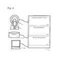
- FIG. 4is a diagram illustrating a relationship of the various modules according to exemplary embodiments of the present invention.
- a medical imaging device 41for example, an MRI scanner, may be used to image a patient 42 .
- the acquired image sequencemay be transmitted to an image processing device 43 .
- the image processing device 43may include multiple modules 44 - 46 .
- Each of the included modulesmay be implemented by software running on a data processing device such as a computer. The same image processing device may be used for executing the software for one or more of the modules.
- a landmark detection module 44may be responsible for automatically detecting one or more landmarks within the acquired image.
- a propagation module 45may then be responsible for automatically propagating the detected landmarks throughout the image sequence.
- a structure fitting module 46may then be used to fit a structure to the image sequence based on the propagated landmarks.
- the structure fitting modulemay be responsible for fitting the imaging plane.
- exemplary embodiments of the present inventionare not limited to the fitting of an imaging plane, and any arbitrary structure may be fit as the need arises.
- plane fittingmay be substituted by line fitting or mesh fitting depending upon the underlying structure that is to be estimated.
- modulesmay also be included within the image processing device 43 .
- modulesmay be used to calculate landmark velocities and other diagnostic parameters.
- the image processing device 43may be able to output diagnostic information such as a graph of landmark velocities to a medical records database 47 and/or a display/console device 48 .
- the landmark detection modulemay be responsible for automatically detecting one or more landmarks within the acquired image. Accordingly, the landmark detection module may be used to automatically detect the valve insertion points for the landmark used on a long axis cardiac cine image of the left ventricle.
- the landmarks usedmay include the mitral valve, the aortic valve, or the tricuspid valve.
- the landmark detection modulemay employ an anchoring component to locate the presence of a specific landmark, which may be in this case; the valve insertion points for the landmark used, for example, the mitral valve insertion points.
- the valve insertion pointmay be represented as a bounding box with various parameters such as two parameters of translation, one parameter of orientation, and two parameters of scale.
- a probabilistic boosting treemay then be used to classify each pixel of the image as either object or background.
- a probabilistic boosting tree (PBT)is an example of a generic classifier that may be used; however, other forms of classifiers may be used in addition to or in place of the PBT. Performance of PBT varies for different parameter settings such as the tree depth and the number of weak classifiers in each node. These parameters may be adjusted for individual applications.
- Marginal space learningmay be used to reduce the computational cost associated with searching through the relatively large five-dimensional parameter space. While any search order may be used in the marginal space learning, a suitable order may include position followed by orientation, and then scale.
- Detection of the valve pointsmay be performed in conjunction with a detection of the apex points of the myocardium.
- the detection of the apex pointsmay be used to bolster the detection of the valve points by providing additional anchoring points; however, both anchoring components may first be detected independently in a first stage and then multiple hypotheses may be maintained at each stage of the marginal space learning algorithm used. Those hypotheses that satisfy the joint contextual model for apex and valve points may be maintained.
- the propagation modulemay be responsible for automatically propagating the detected landmarks throughout the image sequence.
- the propagation modulemay serve to propagate each of the detected valve points from image to all other images on a frame-to-frame basis.
- Propagationmay include a modeling and/or forecasting of where the landmarks are likely to be found based on where they have been most recently and at other occasions at a similar point within the cardiac cycle.
- Propagationmay employ, for example, an inverse-consistent image registration algorithm or another suitable registration approach.
- the structure fitting modulemay be used to fit a structure to the image sequence based on the propagated landmarks.
- the structure to be fittedmay be a geometric plane. Landmark detection may be performed on one image frame at a time. The structure may then be fitted to the detected and propagated landmarks.
- stepsmay be taken to ensure that the propagated valve points are consistent. This may be accomplished, for example, by measuring a distance in three dimensions between the centers of the detected valve points along each of the multiple long axis planes. Valve points may be retained provided that the distance between their centers is below a predetermined threshold, which may be, for example, less than a short axis slice spacing.
- a predetermined thresholdwhich may be, for example, less than a short axis slice spacing.
- Such an approach, or other approachesmay be used to prevent gross errors such as the inclusion of the papillary muscles within the fitted imaging plane.
- the planemay be fit through the N mitral valve landmarks.
- the location of each mitral valve landmarkmay be defined as existing at the coordinates (x i , y i , z i ) where i is a number between zero and N that represents the particular mitral valve landmark. Fitting may be performed using a least squares approach or another suitable approach to fitting.
- a covariance matrix Amay be defined as:
- (x c , y c , z c )represents the center of all landmarks taken together.
- Least squares fitting of a plane to a set of pointsmay be solved by minimizing the orthogonal distance between the points and the plane.
- the plane that minimizes this distancemay go through the center of the points and its normal may be the eigenvector corresponding to the smallest eigenvalue.
- the singular value decomposition of a matrix Agenerates the eigenvalues in the diagonal matrix W and the eigenvectors in the matrices U and V.
- exemplary embodiments of the present inventionare not limited to the fitting of a plane of image acquisition to the tracked landmarks and indeed any desired shape may be fitted to the tracked landmarks or the landmarks may be tracked for other purposes that do not require shape fitting.
- any desired shapemay be fitted to the tracked landmarks or the landmarks may be tracked for other purposes that do not require shape fitting.
- Each of these permutationsshould be understood as falling within the scope of the present inventive concept.
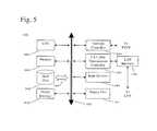
- FIG. 5shows an example of a computer system which may implement a method and system of the present disclosure.
- the system and method of the present disclosuremay be implemented in the form of a software application running on a computer system, for example, a mainframe, personal computer (PC), handheld computer, server, etc.
- the software applicationmay be stored on a recording media locally accessible by the computer system and accessible via a hard wired or wireless connection to a network, for example, a local area network, or the Internet.
- the computer system referred to generally as system 1000may include, for example, a central processing unit (CPU) 1001 , random access memory (RAM) 1004 , a printer interface 1010 , a display unit 1011 , a local area network (LAN) data transmission controller 1005 , a LAN interface 1006 , a network controller 1003 , an internal bus 1002 , and one or more input devices 1009 , for example, a keyboard, mouse etc.
- the system 1000may be connected to a data storage device, for example, a hard disk, 1008 via a link 1007 .
Landscapes
- Physics & Mathematics (AREA)
- Health & Medical Sciences (AREA)
- Nuclear Medicine, Radiotherapy & Molecular Imaging (AREA)
- Vascular Medicine (AREA)
- General Health & Medical Sciences (AREA)
- Radiology & Medical Imaging (AREA)
- Engineering & Computer Science (AREA)
- Signal Processing (AREA)
- High Energy & Nuclear Physics (AREA)
- Condensed Matter Physics & Semiconductors (AREA)
- General Physics & Mathematics (AREA)
- Magnetic Resonance Imaging Apparatus (AREA)
Abstract
Description
Claims (19)
Priority Applications (1)
| Application Number | Priority Date | Filing Date | Title |
|---|---|---|---|
| US13/239,530US8792699B2 (en) | 2010-09-29 | 2011-09-22 | Motion tracking for clinical parameter derivation and adaptive flow acquisition in magnetic resonance imaging |
Applications Claiming Priority (5)
| Application Number | Priority Date | Filing Date | Title |
|---|---|---|---|
| US38759010P | 2010-09-29 | 2010-09-29 | |
| US38814010P | 2010-09-30 | 2010-09-30 | |
| US39064810P | 2010-10-07 | 2010-10-07 | |
| US41245510P | 2010-11-11 | 2010-11-11 | |
| US13/239,530US8792699B2 (en) | 2010-09-29 | 2011-09-22 | Motion tracking for clinical parameter derivation and adaptive flow acquisition in magnetic resonance imaging |
Publications (2)
| Publication Number | Publication Date |
|---|---|
| US20120076382A1 US20120076382A1 (en) | 2012-03-29 |
| US8792699B2true US8792699B2 (en) | 2014-07-29 |
Family
ID=45870713
Family Applications (1)
| Application Number | Title | Priority Date | Filing Date |
|---|---|---|---|
| US13/239,530Active2032-06-04US8792699B2 (en) | 2010-09-29 | 2011-09-22 | Motion tracking for clinical parameter derivation and adaptive flow acquisition in magnetic resonance imaging |
Country Status (1)
| Country | Link |
|---|---|
| US (1) | US8792699B2 (en) |
Cited By (20)
| Publication number | Priority date | Publication date | Assignee | Title |
|---|---|---|---|---|
| US9034032B2 (en) | 2011-10-19 | 2015-05-19 | Twelve, Inc. | Prosthetic heart valve devices, prosthetic mitral valves and associated systems and methods |
| US9125740B2 (en) | 2011-06-21 | 2015-09-08 | Twelve, Inc. | Prosthetic heart valve devices and associated systems and methods |
| US9421098B2 (en) | 2010-12-23 | 2016-08-23 | Twelve, Inc. | System for mitral valve repair and replacement |
| US9579198B2 (en) | 2012-03-01 | 2017-02-28 | Twelve, Inc. | Hydraulic delivery systems for prosthetic heart valve devices and associated methods |
| US9655722B2 (en) | 2011-10-19 | 2017-05-23 | Twelve, Inc. | Prosthetic heart valve devices, prosthetic mitral valves and associated systems and methods |
| US9763780B2 (en) | 2011-10-19 | 2017-09-19 | Twelve, Inc. | Devices, systems and methods for heart valve replacement |
| US9901443B2 (en) | 2011-10-19 | 2018-02-27 | Twelve, Inc. | Prosthetic heart valve devices, prosthetic mitral valves and associated systems and methods |
| US10111747B2 (en) | 2013-05-20 | 2018-10-30 | Twelve, Inc. | Implantable heart valve devices, mitral valve repair devices and associated systems and methods |
| US10238490B2 (en) | 2015-08-21 | 2019-03-26 | Twelve, Inc. | Implant heart valve devices, mitral valve repair devices and associated systems and methods |
| US10265172B2 (en) | 2016-04-29 | 2019-04-23 | Medtronic Vascular, Inc. | Prosthetic heart valve devices with tethered anchors and associated systems and methods |
| US10433961B2 (en) | 2017-04-18 | 2019-10-08 | Twelve, Inc. | Delivery systems with tethers for prosthetic heart valve devices and associated methods |
| US10575950B2 (en) | 2017-04-18 | 2020-03-03 | Twelve, Inc. | Hydraulic systems for delivering prosthetic heart valve devices and associated methods |
| US10646338B2 (en) | 2017-06-02 | 2020-05-12 | Twelve, Inc. | Delivery systems with telescoping capsules for deploying prosthetic heart valve devices and associated methods |
| US10702378B2 (en) | 2017-04-18 | 2020-07-07 | Twelve, Inc. | Prosthetic heart valve device and associated systems and methods |
| US10702380B2 (en) | 2011-10-19 | 2020-07-07 | Twelve, Inc. | Devices, systems and methods for heart valve replacement |
| US10709591B2 (en) | 2017-06-06 | 2020-07-14 | Twelve, Inc. | Crimping device and method for loading stents and prosthetic heart valves |
| US10729541B2 (en) | 2017-07-06 | 2020-08-04 | Twelve, Inc. | Prosthetic heart valve devices and associated systems and methods |
| US10786352B2 (en) | 2017-07-06 | 2020-09-29 | Twelve, Inc. | Prosthetic heart valve devices and associated systems and methods |
| US10792151B2 (en) | 2017-05-11 | 2020-10-06 | Twelve, Inc. | Delivery systems for delivering prosthetic heart valve devices and associated methods |
| US11202704B2 (en) | 2011-10-19 | 2021-12-21 | Twelve, Inc. | Prosthetic heart valve devices, prosthetic mitral valves and associated systems and methods |
Families Citing this family (3)
| Publication number | Priority date | Publication date | Assignee | Title |
|---|---|---|---|---|
| EP3086287B1 (en)* | 2015-04-24 | 2017-10-11 | Pie Medical Imaging BV | Flow analysis in 4d mr image data |
| EP3621028B1 (en)* | 2018-09-07 | 2021-10-06 | 3mensio Medical Imaging B.V. | Method, device and system for dynamic analysis from sequences of volumetric images |
| KR102847471B1 (en)* | 2025-01-20 | 2025-08-21 | 주식회사 메디픽셀 | Method for determining frame through cardiac cycle prediction, method for generating 3d data, and electronic device performing the same |
Citations (14)
| Publication number | Priority date | Publication date | Assignee | Title |
|---|---|---|---|---|
| US5435310A (en)* | 1993-06-23 | 1995-07-25 | University Of Washington | Determining cardiac wall thickness and motion by imaging and three-dimensional modeling |
| US20020072672A1 (en)* | 2000-12-07 | 2002-06-13 | Roundhill David N. | Analysis of cardiac performance using ultrasonic diagnostic images |
| US20030031357A1 (en)* | 2001-06-25 | 2003-02-13 | Lothar Wenzel | System and method for analyzing an image |
| US20030153823A1 (en)* | 1998-08-25 | 2003-08-14 | Geiser Edward A. | Method for automated analysis of apical four-chamber images of the heart |
| US20030160786A1 (en)* | 2002-02-28 | 2003-08-28 | Johnson Richard K. | Automatic determination of borders of body structures |
| US20040223636A1 (en)* | 1999-11-19 | 2004-11-11 | Edic Peter Michael | Feature quantification from multidimensional image data |
| US20070014452A1 (en)* | 2003-12-01 | 2007-01-18 | Mitta Suresh | Method and system for image processing and assessment of a state of a heart |
| US20080085043A1 (en)* | 2004-12-24 | 2008-04-10 | Nozomi Watanabe | Cardiac Valve Data Measuring Method And Device |
| US20090231335A1 (en)* | 2006-07-05 | 2009-09-17 | Koninklijke Philips Electronics N.V. | Prediction of cardiac shape by a motion model |
| US7963925B1 (en)* | 2005-01-26 | 2011-06-21 | Schecter Stuart O | Method and apparatus for defining the effect of atrial arrhythmias on cardiac performance and directing therapy using a plurality of intrinsically and extrinsically derived signals |
| US8131043B2 (en)* | 2005-09-16 | 2012-03-06 | The Ohio State University | Method and apparatus for detecting interventricular dyssynchrony |
| US20120087561A1 (en)* | 2010-10-12 | 2012-04-12 | Siemens Corporation | Interaction method for regions of-interest in time series images |
| US8199994B2 (en)* | 2009-03-13 | 2012-06-12 | International Business Machines Corporation | Automatic analysis of cardiac M-mode views |
| US8280136B2 (en)* | 2005-09-16 | 2012-10-02 | The Ohio State University | Method and apparatus for detecting intraventricular dyssynchrony |
- 2011
- 2011-09-22USUS13/239,530patent/US8792699B2/enactiveActive
Patent Citations (14)
| Publication number | Priority date | Publication date | Assignee | Title |
|---|---|---|---|---|
| US5435310A (en)* | 1993-06-23 | 1995-07-25 | University Of Washington | Determining cardiac wall thickness and motion by imaging and three-dimensional modeling |
| US20030153823A1 (en)* | 1998-08-25 | 2003-08-14 | Geiser Edward A. | Method for automated analysis of apical four-chamber images of the heart |
| US20040223636A1 (en)* | 1999-11-19 | 2004-11-11 | Edic Peter Michael | Feature quantification from multidimensional image data |
| US20020072672A1 (en)* | 2000-12-07 | 2002-06-13 | Roundhill David N. | Analysis of cardiac performance using ultrasonic diagnostic images |
| US20030031357A1 (en)* | 2001-06-25 | 2003-02-13 | Lothar Wenzel | System and method for analyzing an image |
| US20030160786A1 (en)* | 2002-02-28 | 2003-08-28 | Johnson Richard K. | Automatic determination of borders of body structures |
| US20070014452A1 (en)* | 2003-12-01 | 2007-01-18 | Mitta Suresh | Method and system for image processing and assessment of a state of a heart |
| US20080085043A1 (en)* | 2004-12-24 | 2008-04-10 | Nozomi Watanabe | Cardiac Valve Data Measuring Method And Device |
| US7963925B1 (en)* | 2005-01-26 | 2011-06-21 | Schecter Stuart O | Method and apparatus for defining the effect of atrial arrhythmias on cardiac performance and directing therapy using a plurality of intrinsically and extrinsically derived signals |
| US8131043B2 (en)* | 2005-09-16 | 2012-03-06 | The Ohio State University | Method and apparatus for detecting interventricular dyssynchrony |
| US8280136B2 (en)* | 2005-09-16 | 2012-10-02 | The Ohio State University | Method and apparatus for detecting intraventricular dyssynchrony |
| US20090231335A1 (en)* | 2006-07-05 | 2009-09-17 | Koninklijke Philips Electronics N.V. | Prediction of cardiac shape by a motion model |
| US8199994B2 (en)* | 2009-03-13 | 2012-06-12 | International Business Machines Corporation | Automatic analysis of cardiac M-mode views |
| US20120087561A1 (en)* | 2010-10-12 | 2012-04-12 | Siemens Corporation | Interaction method for regions of-interest in time series images |
Cited By (64)
| Publication number | Priority date | Publication date | Assignee | Title |
|---|---|---|---|---|
| US11571303B2 (en) | 2010-12-23 | 2023-02-07 | Twelve, Inc. | System for mitral valve repair and replacement |
| US12178702B2 (en) | 2010-12-23 | 2024-12-31 | Twelve, Inc. | System for mitral valve repair and replacement |
| US10517725B2 (en) | 2010-12-23 | 2019-12-31 | Twelve, Inc. | System for mitral valve repair and replacement |
| US9421098B2 (en) | 2010-12-23 | 2016-08-23 | Twelve, Inc. | System for mitral valve repair and replacement |
| US9572662B2 (en) | 2011-06-21 | 2017-02-21 | Twelve, Inc. | Prosthetic heart valve devices and associated systems and methods |
| US9125740B2 (en) | 2011-06-21 | 2015-09-08 | Twelve, Inc. | Prosthetic heart valve devices and associated systems and methods |
| US10028827B2 (en) | 2011-06-21 | 2018-07-24 | Twelve, Inc. | Prosthetic heart valve devices and associated systems and methods |
| US11523900B2 (en) | 2011-06-21 | 2022-12-13 | Twelve, Inc. | Prosthetic heart valve devices and associated systems and methods |
| US9579196B2 (en) | 2011-06-21 | 2017-02-28 | Twelve, Inc. | Prosthetic heart valve devices and associated systems and methods |
| US9585751B2 (en) | 2011-06-21 | 2017-03-07 | Twelve, Inc. | Prosthetic heart valve devices and associated systems and methods |
| US10751173B2 (en) | 2011-06-21 | 2020-08-25 | Twelve, Inc. | Prosthetic heart valve devices and associated systems and methods |
| US11712334B2 (en) | 2011-06-21 | 2023-08-01 | Twelve, Inc. | Prosthetic heart valve devices and associated systems and methods |
| US10034750B2 (en) | 2011-06-21 | 2018-07-31 | Twelve, Inc. | Prosthetic heart valve devices and associated systems and methods |
| US11628063B2 (en) | 2011-10-19 | 2023-04-18 | Twelve, Inc. | Prosthetic heart valve devices, prosthetic mitral valves and associated systems and methods |
| US9039757B2 (en) | 2011-10-19 | 2015-05-26 | Twelve, Inc. | Prosthetic heart valve devices, prosthetic mitral valves and associated systems and methods |
| US9901443B2 (en) | 2011-10-19 | 2018-02-27 | Twelve, Inc. | Prosthetic heart valve devices, prosthetic mitral valves and associated systems and methods |
| US10052204B2 (en) | 2011-10-19 | 2018-08-21 | Twelve, Inc. | Prosthetic heart valve devices, prosthetic mitral valves and associated systems and methods |
| US12370042B2 (en) | 2011-10-19 | 2025-07-29 | Twelve, Inc. | Devices, systems and methods for heart valve replacement |
| US9034033B2 (en) | 2011-10-19 | 2015-05-19 | Twelve, Inc. | Prosthetic heart valve devices, prosthetic mitral valves and associated systems and methods |
| US11826249B2 (en) | 2011-10-19 | 2023-11-28 | Twelve, Inc. | Devices, systems and methods for heart valve replacement |
| US10299917B2 (en) | 2011-10-19 | 2019-05-28 | Twelve, Inc. | Prosthetic heart valve devices, prosthetic mitral valves and associated systems and methods |
| US10299927B2 (en) | 2011-10-19 | 2019-05-28 | Twelve, Inc. | Prosthetic heart valve devices, prosthetic mitral valves and associated systems and methods |
| US10335278B2 (en) | 2011-10-19 | 2019-07-02 | Twelve, Inc. | Prosthetic heart valve devices, prosthetic mitral valves and associated systems and methods |
| US10016271B2 (en) | 2011-10-19 | 2018-07-10 | Twelve, Inc. | Prosthetic heart valve devices, prosthetic mitral valves and associated systems and methods |
| US9763780B2 (en) | 2011-10-19 | 2017-09-19 | Twelve, Inc. | Devices, systems and methods for heart valve replacement |
| US9034032B2 (en) | 2011-10-19 | 2015-05-19 | Twelve, Inc. | Prosthetic heart valve devices, prosthetic mitral valves and associated systems and methods |
| US11617648B2 (en) | 2011-10-19 | 2023-04-04 | Twelve, Inc. | Prosthetic heart valve devices, prosthetic mitral valves and associated systems and methods |
| US9295552B2 (en) | 2011-10-19 | 2016-03-29 | Twelve, Inc. | Prosthetic heart valve devices, prosthetic mitral valves and associated systems and methods |
| US10702380B2 (en) | 2011-10-19 | 2020-07-07 | Twelve, Inc. | Devices, systems and methods for heart valve replacement |
| US11497603B2 (en) | 2011-10-19 | 2022-11-15 | Twelve, Inc. | Prosthetic heart valve devices, prosthetic mitral valves and associated systems and methods |
| US11202704B2 (en) | 2011-10-19 | 2021-12-21 | Twelve, Inc. | Prosthetic heart valve devices, prosthetic mitral valves and associated systems and methods |
| US9655722B2 (en) | 2011-10-19 | 2017-05-23 | Twelve, Inc. | Prosthetic heart valve devices, prosthetic mitral valves and associated systems and methods |
| US11197758B2 (en) | 2011-10-19 | 2021-12-14 | Twelve, Inc. | Prosthetic heart valve devices, prosthetic mitral valves and associated systems and methods |
| US10945835B2 (en) | 2011-10-19 | 2021-03-16 | Twelve, Inc. | Prosthetic heart valve devices, prosthetic mitral valves and associated systems and methods |
| US11129714B2 (en) | 2012-03-01 | 2021-09-28 | Twelve, Inc. | Hydraulic delivery systems for prosthetic heart valve devices and associated methods |
| US12161552B2 (en) | 2012-03-01 | 2024-12-10 | Twelve, Inc. | Hydraulic delivery systems for prosthetic heart valve devices and associated methods |
| US9579198B2 (en) | 2012-03-01 | 2017-02-28 | Twelve, Inc. | Hydraulic delivery systems for prosthetic heart valve devices and associated methods |
| US10111747B2 (en) | 2013-05-20 | 2018-10-30 | Twelve, Inc. | Implantable heart valve devices, mitral valve repair devices and associated systems and methods |
| US11234821B2 (en) | 2013-05-20 | 2022-02-01 | Twelve, Inc. | Implantable heart valve devices, mitral valve repair devices and associated systems and methods |
| US10820996B2 (en) | 2015-08-21 | 2020-11-03 | Twelve, Inc. | Implantable heart valve devices, mitral valve repair devices and associated systems and methods |
| US11576782B2 (en) | 2015-08-21 | 2023-02-14 | Twelve, Inc. | Implantable heart valve devices, mitral valve repair devices and associated systems and methods |
| US10238490B2 (en) | 2015-08-21 | 2019-03-26 | Twelve, Inc. | Implant heart valve devices, mitral valve repair devices and associated systems and methods |
| US12109113B2 (en) | 2016-04-29 | 2024-10-08 | Medtronic Vascular, Inc. | Prosthetic heart valve devices with tethered anchors and associated systems and methods |
| US11033390B2 (en) | 2016-04-29 | 2021-06-15 | Medtronic Vascular, Inc. | Prosthetic heart valve devices with tethered anchors and associated systems and methods |
| US10265172B2 (en) | 2016-04-29 | 2019-04-23 | Medtronic Vascular, Inc. | Prosthetic heart valve devices with tethered anchors and associated systems and methods |
| US12201523B2 (en) | 2017-04-18 | 2025-01-21 | Twelve, Inc. | Hydraulic systems for delivering prosthetic heart valve devices and associated methods |
| US10702378B2 (en) | 2017-04-18 | 2020-07-07 | Twelve, Inc. | Prosthetic heart valve device and associated systems and methods |
| US11389295B2 (en) | 2017-04-18 | 2022-07-19 | Twelve, Inc. | Delivery systems with tethers for prosthetic heart valve devices and associated methods |
| US10575950B2 (en) | 2017-04-18 | 2020-03-03 | Twelve, Inc. | Hydraulic systems for delivering prosthetic heart valve devices and associated methods |
| US11654021B2 (en) | 2017-04-18 | 2023-05-23 | Twelve, Inc. | Prosthetic heart valve device and associated systems and methods |
| US10433961B2 (en) | 2017-04-18 | 2019-10-08 | Twelve, Inc. | Delivery systems with tethers for prosthetic heart valve devices and associated methods |
| US11737873B2 (en) | 2017-04-18 | 2023-08-29 | Twelve, Inc. | Hydraulic systems for delivering prosthetic heart valve devices and associated methods |
| US10792151B2 (en) | 2017-05-11 | 2020-10-06 | Twelve, Inc. | Delivery systems for delivering prosthetic heart valve devices and associated methods |
| US11786370B2 (en) | 2017-05-11 | 2023-10-17 | Twelve, Inc. | Delivery systems for delivering prosthetic heart valve devices and associated methods |
| US10646338B2 (en) | 2017-06-02 | 2020-05-12 | Twelve, Inc. | Delivery systems with telescoping capsules for deploying prosthetic heart valve devices and associated methods |
| US11559398B2 (en) | 2017-06-02 | 2023-01-24 | Twelve, Inc. | Delivery systems with telescoping capsules for deploying prosthetic heart valve devices and associated methods |
| US12329639B2 (en) | 2017-06-02 | 2025-06-17 | Twelve, Inc. | Delivery systems with telescoping capsules for deploying prosthetic heart valve devices and associated methods |
| US10709591B2 (en) | 2017-06-06 | 2020-07-14 | Twelve, Inc. | Crimping device and method for loading stents and prosthetic heart valves |
| US11464659B2 (en) | 2017-06-06 | 2022-10-11 | Twelve, Inc. | Crimping device for loading stents and prosthetic heart valves |
| US12274632B2 (en) | 2017-06-06 | 2025-04-15 | Twelve, Inc. | Crimping device for loading stents and prosthetic heart valves |
| US11877926B2 (en) | 2017-07-06 | 2024-01-23 | Twelve, Inc. | Prosthetic heart valve devices and associated systems and methods |
| US12016772B2 (en) | 2017-07-06 | 2024-06-25 | Twelve, Inc. | Prosthetic heart valve devices and associated systems and methods |
| US10729541B2 (en) | 2017-07-06 | 2020-08-04 | Twelve, Inc. | Prosthetic heart valve devices and associated systems and methods |
| US10786352B2 (en) | 2017-07-06 | 2020-09-29 | Twelve, Inc. | Prosthetic heart valve devices and associated systems and methods |
Also Published As
| Publication number | Publication date |
|---|---|
| US20120076382A1 (en) | 2012-03-29 |
Similar Documents
| Publication | Publication Date | Title |
|---|---|---|
| US8792699B2 (en) | Motion tracking for clinical parameter derivation and adaptive flow acquisition in magnetic resonance imaging | |
| US20240346652A1 (en) | Flow analysis in 4d mr image data | |
| JP5108905B2 (en) | Method and apparatus for automatically identifying image views in a 3D dataset | |
| Tsang et al. | Transthoracic 3D echocardiographic left heart chamber quantification using an automated adaptive analytics algorithm | |
| Luijnenburg et al. | Intra-observer and interobserver variability of biventricular function, volumes and mass in patients with congenital heart disease measured by CMR imaging | |
| US9629615B1 (en) | Combined B-mode / tissue doppler approach for improved cardiac motion estimation in echocardiographic images | |
| Kaku et al. | Age-related normal range of left ventricular strain and torsion using three-dimensional speckle-tracking echocardiography | |
| Gopal et al. | Freehand three-dimensional echocardiography for measurement of left ventricular mass: in vivo anatomic validation using explanted human hearts | |
| EP2392942B1 (en) | Cardiac flow quantification with volumetric imaging data | |
| Dragulescu et al. | Echocardiographic assessment of right ventricular volumes after surgical repair of tetralogy of Fallot: clinical validation of a new echocardiographic method | |
| US20160314587A1 (en) | Processing apparatus, processing method, and non-transitory computer-readable storage medium | |
| Kim et al. | Automatic segmentation of the left ventricle in echocardiographic images using convolutional neural networks | |
| Mazaheri et al. | Echocardiography image segmentation: A survey | |
| US20160358328A1 (en) | Method for post-processing flow-sensitive phase contrast magnetic resonance images | |
| Zhao et al. | MITEA: A dataset for machine learning segmentation of the left ventricle in 3D echocardiography using subject-specific labels from cardiac magnetic resonance imaging | |
| Lu et al. | Automatic delineation of left and right ventricles in cardiac MRI sequences using a joint ventricular model | |
| EP2498222B1 (en) | Method and system for regression-based 4D mitral valve segmentation from 2D+T magnetic resonance imaging slices | |
| Bäck et al. | Assessment of transmitral and left atrial appendage flow rate from cardiac 4D-CT | |
| Tavakoli et al. | Tissue Doppler imaging optical flow (TDIOF): A combined B-mode and tissue Doppler approach for cardiac motion estimation in echocardiographic images | |
| Corsi et al. | Left ventricular endocardial surface detection based on real-time 3D echocardiographic data | |
| Linguraru et al. | Real-time tracking and shape analysis of atrial septal defects in 3D echocardiography | |
| Perperidis | Spatio-temporal registration and modelling of the heart using cardiovascular MR imaging | |
| Nyns et al. | Evaluation of knowledge-based reconstruction for magnetic resonance volumetry of the right ventricle in tetralogy of Fallot | |
| Garson et al. | Guiding automated left ventricular chamber segmentation in cardiac imaging using the concept of conserved myocardial volume | |
| Lakshmi | Anatomical photo representations for cardiac imaging training |
Legal Events
| Date | Code | Title | Description |
|---|---|---|---|
| AS | Assignment | Owner name:SIEMENS CORPORATION, NEW JERSEY Free format text:ASSIGNMENT OF ASSIGNORS INTEREST;ASSIGNORS:GUETTER, CHRISTOPH;GUEHRING, JENS;JOLLY, MARIE-PIERRE;AND OTHERS;SIGNING DATES FROM 20130731 TO 20130924;REEL/FRAME:031277/0027 | |
| AS | Assignment | Owner name:SIEMENS MEDICAL SOLUTIONS USA, INC., PENNSYLVANIA Free format text:ASSIGNMENT OF ASSIGNORS INTEREST;ASSIGNOR:WEALE, PETER;REEL/FRAME:033056/0873 Effective date:20140602 | |
| AS | Assignment | Owner name:SIEMENS AKTIENGESELLSCHAFT, GERMANY Free format text:ASSIGNMENT OF ASSIGNORS INTEREST;ASSIGNOR:SIEMENS CORPORATION;REEL/FRAME:033084/0363 Effective date:20140409 Owner name:SIEMENS AKTIENGESELLSCHAFT, GERMANY Free format text:ASSIGNMENT OF ASSIGNORS INTEREST;ASSIGNOR:SIEMENS MEDICAL SOLUTIONS USA, INC.;REEL/FRAME:033084/0205 Effective date:20140606 | |
| STCF | Information on status: patent grant | Free format text:PATENTED CASE | |
| AS | Assignment | Owner name:SIEMENS HEALTHCARE GMBH, GERMANY Free format text:ASSIGNMENT OF ASSIGNORS INTEREST;ASSIGNOR:SIEMENS AKTIENGESELLSCHAFT;REEL/FRAME:039271/0561 Effective date:20160610 | |
| MAFP | Maintenance fee payment | Free format text:PAYMENT OF MAINTENANCE FEE, 4TH YEAR, LARGE ENTITY (ORIGINAL EVENT CODE: M1551) Year of fee payment:4 | |
| MAFP | Maintenance fee payment | Free format text:PAYMENT OF MAINTENANCE FEE, 8TH YEAR, LARGE ENTITY (ORIGINAL EVENT CODE: M1552); ENTITY STATUS OF PATENT OWNER: LARGE ENTITY Year of fee payment:8 | |
| AS | Assignment | Owner name:SIEMENS HEALTHINEERS AG, GERMANY Free format text:ASSIGNMENT OF ASSIGNORS INTEREST;ASSIGNOR:SIEMENS HEALTHCARE GMBH;REEL/FRAME:066088/0256 Effective date:20231219 | |
| AS | Assignment | Owner name:SIEMENS HEALTHINEERS AG, GERMANY Free format text:CORRECTIVE ASSIGNMENT TO CORRECT THE ASSIGNEE PREVIOUSLY RECORDED AT REEL: 066088 FRAME: 0256. ASSIGNOR(S) HEREBY CONFIRMS THE ASSIGNMENT;ASSIGNOR:SIEMENS HEALTHCARE GMBH;REEL/FRAME:071178/0246 Effective date:20231219 |