US8792256B2 - Controller for a switch and method of operating the same - Google Patents
Controller for a switch and method of operating the sameDownload PDFInfo
- Publication number
- US8792256B2 US8792256B2US13/360,516US201213360516AUS8792256B2US 8792256 B2US8792256 B2US 8792256B2US 201213360516 AUS201213360516 AUS 201213360516AUS 8792256 B2US8792256 B2US 8792256B2
- Authority
- US
- United States
- Prior art keywords
- voltage
- switch
- mode
- controller
- recited
- Prior art date
- Legal status (The legal status is an assumption and is not a legal conclusion. Google has not performed a legal analysis and makes no representation as to the accuracy of the status listed.)
- Active, expires
Links
- 238000000034methodMethods0.000titleclaimsabstractdescription25
- 230000005669field effectEffects0.000claimsdescription4
- 230000000977initiatory effectEffects0.000claims1
- 238000004804windingMethods0.000description19
- 239000003990capacitorSubstances0.000description10
- 238000010586diagramMethods0.000description9
- 230000000295complement effectEffects0.000description7
- 230000008901benefitEffects0.000description6
- 230000008569processEffects0.000description6
- 238000004519manufacturing processMethods0.000description4
- 230000001419dependent effectEffects0.000description3
- 238000001514detection methodMethods0.000description3
- 239000000203mixtureSubstances0.000description3
- 230000001276controlling effectEffects0.000description2
- 238000005070samplingMethods0.000description2
- 230000007704transitionEffects0.000description2
- 230000002159abnormal effectEffects0.000description1
- 230000004075alterationEffects0.000description1
- 230000033228biological regulationEffects0.000description1
- 230000008859changeEffects0.000description1
- 238000010276constructionMethods0.000description1
- 230000007423decreaseEffects0.000description1
- 230000005347demagnetizationEffects0.000description1
- 238000002955isolationMethods0.000description1
- 229910044991metal oxideInorganic materials0.000description1
- 150000004706metal oxidesChemical class0.000description1
- 230000001105regulatory effectEffects0.000description1
- 230000004044responseEffects0.000description1
- 239000004065semiconductorSubstances0.000description1
- 238000006467substitution reactionMethods0.000description1
- 230000001360synchronised effectEffects0.000description1
Images


Classifications
- H—ELECTRICITY
- H02—GENERATION; CONVERSION OR DISTRIBUTION OF ELECTRIC POWER
- H02M—APPARATUS FOR CONVERSION BETWEEN AC AND AC, BETWEEN AC AND DC, OR BETWEEN DC AND DC, AND FOR USE WITH MAINS OR SIMILAR POWER SUPPLY SYSTEMS; CONVERSION OF DC OR AC INPUT POWER INTO SURGE OUTPUT POWER; CONTROL OR REGULATION THEREOF
- H02M3/00—Conversion of DC power input into DC power output
- H02M3/22—Conversion of DC power input into DC power output with intermediate conversion into AC
- H02M3/24—Conversion of DC power input into DC power output with intermediate conversion into AC by static converters
- H02M3/28—Conversion of DC power input into DC power output with intermediate conversion into AC by static converters using discharge tubes with control electrode or semiconductor devices with control electrode to produce the intermediate AC
- H02M3/325—Conversion of DC power input into DC power output with intermediate conversion into AC by static converters using discharge tubes with control electrode or semiconductor devices with control electrode to produce the intermediate AC using devices of a triode or a transistor type requiring continuous application of a control signal
- H02M3/335—Conversion of DC power input into DC power output with intermediate conversion into AC by static converters using discharge tubes with control electrode or semiconductor devices with control electrode to produce the intermediate AC using devices of a triode or a transistor type requiring continuous application of a control signal using semiconductor devices only
- H—ELECTRICITY
- H02—GENERATION; CONVERSION OR DISTRIBUTION OF ELECTRIC POWER
- H02M—APPARATUS FOR CONVERSION BETWEEN AC AND AC, BETWEEN AC AND DC, OR BETWEEN DC AND DC, AND FOR USE WITH MAINS OR SIMILAR POWER SUPPLY SYSTEMS; CONVERSION OF DC OR AC INPUT POWER INTO SURGE OUTPUT POWER; CONTROL OR REGULATION THEREOF
- H02M1/00—Details of apparatus for conversion
- H02M1/36—Means for starting or stopping converters
Definitions
- the present inventionis directed, in general, to power electronics and, more specifically, to a controller for a switch and method of operating the same.
- a switched-mode power converter(also referred to as a “power converter”) is a power supply or power processing circuit that converts an input voltage waveform into a specified output voltage waveform.
- DC-DC power convertersconvert a direct current (“DC”) input voltage into a DC output voltage.
- Controllers associated with the power convertersmanage an operation thereof by controlling conduction periods of power switches employed therein.
- the controllersare coupled between an input and output of the power converter in a feedback loop configuration (also referred to as a “control loop” or “closed control loop”).
- the controllermeasures an output characteristic (e.g., an output voltage, an output current, or a combination of an output voltage and an output current) of the power converter, and based thereon modifies a duty cycle of a power switch of the power converter.
- the duty cycle “D”is a ratio represented by a conduction period of a power switch to a switching period thereof.
- the switching periodincludes the conduction period of the power switch (represented by the duty cycle “D”) and a non-conduction period of the power switch (represented by the complementary duty cycle (“1-D”).
- the duty cycle for the power switchwould be 0.5 (or 50 percent).
- the switched-mode power converterscan be constructed with different types of power switches such as bipolar transistors, metal-oxide semiconductor field-effect transistors (“MOSFETs”) or insulated gate bipolar transistors (“IGBTs”). At low power levels, for example, an output power less than 100 watts (“W”), the MOSFETs and bipolar transistors are most commonly used for power switches. While MOSFETs can work at higher switching frequency, which enables smaller designs, bipolar transistors are available at lower cost. Additionally, the different switches employ different drivers for their respective control terminals. As a result, separate driver integrated circuits are inventoried to accommodate the use of different switches in a design of a circuit (e.g., a power converter) employing the same.
- a circuite.g., a power converter
- the controlleris configured to measure a voltage of a control terminal of the switch and select a first mode of operation if the voltage of the control terminal is greater than a threshold voltage, and a second mode of operation if the voltage of the control terminal is less than the threshold voltage.
- FIGS. 1 and 2illustrate schematic diagrams of embodiments of power converters constructed according to the principles of the present invention
- FIG. 3illustrates a schematic diagram of different switches demonstrating the principles of the present invention
- FIGS. 4 and 5illustrate graphical representations representing the differences between switches according to the principles of the present invention
- FIG. 6illustrates a block diagram of an embodiment of a controller constructed according to the principles of the present invention.
- FIGS. 7 to 12illustrated diagrams of embodiments of portions of a controller constructed according to the principles of the present invention.
- the present inventionwill be described with respect to exemplary embodiments in a specific context, namely, a controller operable with different types of switches such as a MOSFET or bipolar transistor. While the principles of the present invention will be described in the environment of a power converter, any application that may benefit from the controller as described herein including a power amplifier or a motor controller is well within the broad scope of the present invention.
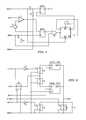
- FIG. 1illustrated is a schematic diagram of an embodiment of a power converter constructed according to the principles of the present invention.
- the power converteris configured to convert AC mains voltage (designated “Vac in”) to a regulated DC output voltage Vout.
- a power train (e.g., a flyback power train) of the power converter(also referred to as a “flyback power converter”) includes a power switch Q 1 coupled to a source of electrical power (e.g., the AC mains) via an input filter (including capacitors C 1 , C 2 and an inductor L 2 ) to provide a filtered DC input voltage Vin to a magnetic device (e.g., an isolating transformer or transformer TX 1 ).
- a magnetic devicee.g., an isolating transformer or transformer TX 1
- a resistor R 1represents an impedance of the AC mains.
- the power convertermay also include an electromagnetic interference filter between the AC mains voltage Vac and a bridge rectifier 110 .
- the transformer TX 1has a primary winding P 1 and a secondary winding S 1 with a turns ratio that is selected to provide the output voltage Vout with consideration of a resulting duty cycle and stress on power train components.
- the power switch Q 1(e.g., a MOSFET) is controlled by a controller (e.g., an application specific integrated circuit (“ASIC”)) 120 that controls the power switch Q 1 to be conducting for a duty cycle.
- the power switch Q 1conducts in response to drive signal such as a gate drive voltage dry produced by the controller 120 with a switching frequency (often designated as “f s ”).
- the duty cycleis controlled (e.g., adjusted) by the controller 120 to regulate an output characteristic of the power converter such as an output voltage Vout, an output current lout, or a combination thereof.
- a feedback signal FBtraverses a feedback path (a portion of which is identified as 130 ) emanating from a bias winding P 2 of the transformer TX 1 to enable the controller 120 to control the duty cycle to regulate the output characteristic of the power converter proportional to a bias voltage VP from the bias winding P 2 .
- a series circuit arrangement of resistors R 14 , R 23provides a voltage divider function to scale the voltage produced for the feedback signal FB by the bias winding P 2 of the transformer TX 1 .
- the bias voltage VPis substantially proportional to a voltage across the secondary winding S 1 depending on a turns ratio between the primary winding P 1 and the secondary winding S 1 .
- the voltage produced across the winding P 2is rectified by a diode D 6 and charges a capacitor C 4 to provide an bias voltage VP for the controller 120 .
- a resistor R 25provides a current-limit function to limit a charging current into the capacitor C 4 .
- a resistor R 8provides a start-up charge for the capacitor C 4 .
- the AC voltage or alternating voltage appearing on the secondary winding S 1 of the transformer TX 1is rectified by an auxiliary power switch (e.g., diode D 7 or, alternatively, by a synchronous rectifier, not shown), and the DC component of the resulting waveform is coupled to the output through the low-pass output filter including an output filter capacitor C 9 to produce the output voltage Vout.
- a resistor R 18is included in the circuit to ensure that there is still power consumption when a load is disconnected from the output terminals out+, out ⁇ of the power converter. This ensures that the switching frequency at no load is high enough to react sufficiently to a change in the load.
- a current sensor R 15is coupled to the power switch Q 1 and provides a voltage that is proportional to a current in the primary switch (Ip ⁇ Ipri, wherein Ipri is a primary current flowing through the primary winding P 1 of the transformer TX 1 ) for the controller 120 . This voltage is used to determine the duration of the conduction period of the power switch Q 1 .
- a primary current Ipri(e.g., an inductor current) flowing through the primary winding P 1 of the transformer TX 1 increases as current flows from the input through the power switch Q 1 .
- the power switch Q 1is transitioned to a non-conducting state. Residual magnetic energy stored in the transformer TX 1 causes conduction of a secondary current Isec through the diode D 7 when the power switch Q 1 is off.
- the diode D 7which is coupled to the output filter capacitor C 9 , provides a path to maintain continuity of a magnetizing current of the transformer TX 1 .
- the magnetizing current flowing through the secondary winding S 1 of the transformer TX 1decreases.
- the duty cycle of the power switch Q 1may be controlled (e.g., adjusted) to maintain a regulation of or regulate the output voltage Vout of the power converter.
- a value or a scaled value of the feedback signal FBis compared with a reference voltage within the controller 120 to control the duty cycle D.
- a larger duty cycleimplies that the power switch Q 1 is closed for a longer fraction of the switching period of the power converter.
- the power converteris operable with a switching cycle wherein an input voltage Vin is coupled to the transformer TX 1 for a fraction of a switching period by the power switch Q 1 controlled by controller 120 .
- a voltage produced by the bias winding P 2 during a flyback portion of a switching cyclecan be related to the output voltage Vout by accounting for a turns ratio of the transformer TX 1 and voltage drops in diodes and other circuit elements.
- the voltage produced across the bias winding P 2is employed to produce an estimate of the output voltage Vout, which in turn is used to regulate the same without crossing the isolation boundary of the transformer TX 1 .
- FIG. 2illustrated is a schematic diagram of another embodiment of a power converter constructed according to the principles of the present invention.
- the power switch Q 2 of FIG. 2is a bipolar transistor in lieu of the MOSFET power switch Q 1 illustrated in FIG. 1 .
- the controller 120 of FIGS. 1 and 2is configured to operate with different types of switches as set forth below. As a result, the controller 120 can select first and second modes of operation depending on the type of power switch employed in the power converter. For instance, the controller can select the first mode of operation if the power switch is a MOSFET (see, MOSFET power switch Q 1 in FIG. 1 ) and a second mode of operation if the power switch is a bipolar transistor (see, bipolar transistor power switch Q 2 in FIG. 2 ). It should be understood that the principles of the present invention are not limited to only MOSFETs and bipolar transistors.
- the power converters of FIGS. 1 and 2otherwise include like components that operate in similar ways and, as such, will not hereinafter be described again.
- the first switchis an npn bipolar transistor Q 1 with a base terminal Q 1 -base driven by a drive signal such as a positive drive voltage V 1 through a resistor R 1 .
- the second switchis an n-channel MOSFET Q 2 with a gate terminal Q 2 -G driven by the positive drive voltage V 1 through resistor R 2 .
- the resistors R 1 , R 2are each one kilohm (“k ⁇ ”) resistors. Since the bipolar transistor Q 1 presents a forward-biased junction at its base terminal Q 1 -base, the voltage of the base terminal does not rise more than about 0.7 volts (“V”).
- the gate terminal Q 2 -G of the MOSFET Q 2presents a substantially open circuit to a driver, the voltage thereof rises substantially to the voltage of the drive voltage V 1 , which can be about 10 volts. Accordingly, the voltage at the respective control terminal of each switch can be employed to detect whether the switch is a bipolar transistor or a MOSFET.
- FIGS. 4 and 5illustrated are graphical representations illustrating the differences between switches according to the principles of the present invention.
- FIG. 4illustrates a drive signal such as a drive voltage dry vs. time produced by a pulse-width modulator controller with a drive voltage of 10 volts, and the respective voltages VQ 2 -G, VQ 1 -base at the control terminals of a MOSFET and a bipolar transistor, respectively.
- the voltage VQ 2 -G at the control terminal of the MOSFETrises to about 10 volts
- the voltage VQ 1 -base at the control terminal of the bipolar transistorrises only to about 0.7 volts.
- FIG. 5illustrates current flowing IQ 2 -G into the gate terminal of the MOSFET and current IQ 1 -base flowing into the base terminal of the bipolar transistor.
- a brief pulse of currentflows into the gate terminal of the MOSFET as its gate-to-source capacitance is charged.
- a continuous current of about 10 milliamperes (“mA”)flows into the base terminal of the bipolar transistor. Accordingly, the current flowing into the control terminal of a switch can also be employed to detect the type of switch being used in a circuit.
- FIG. 6illustrated is a block diagram of an embodiment of a controller (e.g., an application specific integrated circuit (“ASIC”)) constructed according to the principles of the present invention.
- the controllerprovides an adaptable drive function dependent on a detected switch embodied in a circuit employing the same (see, e.g., the power converter of FIGS. 1 and 2 ).
- Other types of controllersthat provide an adaptable drive function for a switch dependent on the detected switch are well within the broad scope of the present invention.
- the controllerincludes a sample and hold circuit SundH that estimates the output voltage by sampling a voltage of a bias winding of a transformer (e.g., the bias winding P 2 of the transformer TX 1 in FIGS. 1 and 2 ).
- a comparator circuit Compincludes several comparators to compare a voltage VSuH produced by the sample and hold circuit SundH with a ramp voltage Ref_exp to determine the off time of the drive voltage drv.
- An output of the comparator circuitis a signal designated Freig. When the signal Freig is high, demagnetization of the transformer has been detected and the drive voltage dry of the controller can be switched on.
- a timer (designated “Timer”) of the controllerproduces a pulse-width modulated signal Gin, which determines various conditions under which the drive voltage dry is switched on.
- the comparator circuit Comp and timer “Timer”determine when the drive voltage dry can be switched on for a switch.
- a reference circuit(designated “Reference”) generates various reference voltages used internally by the controller.
- a timing circuit SuHclkprovides timing when sampling is being performed.
- the timing circuit SuHclkuses the output of the timer “Timer” to control the timing when a feedback signal FB (e.g., the feedback signal FB produced by the bias winding P 2 of the transformer Tx 1 of FIGS. 1 and 2 ) is sampled.
- a feedback signal FBe.g., the feedback signal FB produced by the bias winding P 2 of the transformer Tx 1 of FIGS. 1 and 2
- Various circuit configurations to control timing of a feedback signal FBmay be employed to advantage.
- a current control circuit CC_controlcalculates when the controller can be switched on to provide a constant output current because the controller can be employed to control a combination of constant voltage/constant current characteristic of a circuit such as a power converter.
- the off time of the drive voltage dry for a switchis controlled by a combination of the timing circuit SuHclk and the current control circuit CC_control.
- the longer of the off times calculated by the timing circuit SuHclk and the current control circuit CC_controlis taken as controlling for the off time of the drive voltage dry for a switch.
- the calculation of the off timeis longer in the timing circuit SuHclk.
- the timing of the current control circuit CC_controlis longer.
- the comparator circuit Comp, timing circuit SuHclk and the current control circuit CC_controloperate to determine the timing of the drive voltage dry for the switch.
- An overvoltage protection circuit OVP of the controllerprovides overvoltage protection for the power converter, and transitions the controller to a safe mode (i.e., the drive voltage dry is switched off), when an abnormal condition of the bias voltage VP is detected.
- the controlleralso includes a startup circuit (designated “startup”), a switch detector (designated “switch_detector”) and driver (designated “driver”) that will be described in more detail below.
- FIGS. 7 to 11illustrated are diagrams of embodiments of portions of a controller constructed according to the principles of the present invention.
- a startup circuitemployable as the startup circuit (designated “startup”) of FIG. 6 .
- the startup circuitmeasures the bias voltage VP and when the bias voltage VP is higher than a startup level, a start signal “start” is set high to enable operation of the controller.
- the start signal “start”is set low to disable operation of the controller.
- the under-voltage lockout levelis dependent on a switch detect signal FET that represents whether a MOSFET or a bipolar transistor was detected in the circuit such as a power converter.
- the detection of a MOSFETcauses the controller to select a first mode of operation
- the detection of a bipolar transistorcauses the controller to select a second mode of operation.
- the under-voltage lockout levelis set to a higher level when the controller operates in the first mode of operation than when the controller operates in the second mode of operation.
- the startup levelis higher than the under voltage lockout level to ensure that enough energy is stored in the capacitor C 4 to maintain operation of the controller 120 after startup until the voltage at the output has risen high enough to power the controller 120 via the bias winding P 2 of the transformer TX 1 .
- the circuitry 710provides a level shifting function to set the under-voltage lockout level lower when a bipolar transistor is detected.
- the circuitry 710includes comparator U 2 , inverter U 3 , 5-volt voltage-reference V 1 and resistors R 2 , R 3 , R 4 , R 5 , R 6 , R 7 .
- a MOSFETfrequently requires a higher drive voltage at its gate terminal then the base terminal of a bipolar transistor to completely turn the MOSFET on. Accordingly, the under-voltage lockout level at which the controller is enabled to operate is set higher when a MOSFET is detected.
- the circuit illustrated in FIG. 7is configured to produce a lower switch-off voltage than a switch-on voltage.
- the circuitry 720produces a logical output coupled to the non-inverting input of a comparator E 1 .
- the output of the comparator E 1is coupled to both inputs of an OR gate U 1 , the output of which is coupled to the non-inverting input of a comparator E 2 .
- the output of the comparator E 2produces the start signal “start”.
- the comparator E 2 and OR gate U 1increase the slope of the start signal during transition between high and low state.
- the circuitry 720represents a simulated current consumed by the controller to improve accuracy of its operation.
- switch_detectoremployable as the switch detector (designated “switch_detector”) of FIG. 6 .
- the switch detectordetects whether a switch coupled to a drive signal such as the drive voltage dry is, for instance, a MOSFET or a bipolar transistor.
- start signal “start”goes high, which is coupled to a “set” input terminal of latch 2 through the high-pass network formed with a capacitor C 1 and a resistor R 1 , the output Q of latch 2 is set high to initially signal operation in a MOSFET mode (a first mode of operation).
- a pulse-width modulated signal Ginalso referred to as “GIN”
- the output Q of latch 2can be reset low to indicate a bipolar transistor (for a bipolar mode or second mode of operation) if the drive voltage dry of the driver becomes less than a threshold level (e.g., three volts), when the pulse-width modulated signal GIN is high.
- a threshold levele.g., three volts
- the output Q of latch 2is left or can be set high to indicate a MOSFET if the drive voltage dry of the driver becomes greater than the threshold level when the pulse-width modulated signal GIN is high. Timing for these operations is controlled by a comparator U 1 with 3-volt reference Vref coupled to its inverting input.
- the output of the comparator U 1is coupled to the “set” input of latch 1 , the output of which is coupled to an OR gate U 2 to signal when the drive voltage dry is greater than three volts.
- the output of the OR gate U 2is coupled to a D flip-flop U 5 .
- the output of the D flip-flop U 5is coupled to the “reset” input of latch 2 .
- pulse-width modulated signal GINthat is coupled through the high-pass network formed with the capacitor C 2 and the resistor R 2 , the output of which is coupled to the “reset” input of latch 1 .
- the pulse-width modulated signal GINis also coupled to the reset input of the D flip-flop U 5 .
- the driverproduces a series of pulses for the drive signal such as the drive voltage dry to control a switch.
- the switch detect signal FETindicates whether the switch is a MOSFET (for a first mode of operation) or a bipolar transistor (for a second mode of operation). If the switch detect signal FET is high, the switch has been detected as a MOSFET; otherwise, the switch has been detected as a bipolar transistor.
- the pulse-width modulated signal Ginis the signal that determines when the drive voltage dry is high or low. When the pulse-width modulated signal Gin is high, the drive voltage dry is high, and vice versa.
- the complement pulse-width modulated signal GinNis the complement of the pulse-width modulated signal Gin.
- the start signal “start”is a signal that is set high when the controller is in an active mode.
- the signal GNDrepresents local circuit ground.
- a switch S 6In operation, when the switch detect signal FET is high, a switch S 6 is off and a switch S 5 is on.
- An inverter U 2provides signal inversion to control the switches S 5 , S 6 . Accordingly, a current limiter “current_limiter” or the voltage limiter “voltage_limiter” is selected by the switch detect signal FET to control a characteristic of the drive voltage drv.
- the switch detect signal FETis set high, thereby representing the first mode of operation (i.e., the driven switch is assumed to be a MOSFET).
- a switch S 4is switched on when the start signal “start” is high to enable operation of the driver.
- the switch S 4is configured to connect or disconnect the bias voltage VP from the current limiter current_limiter or the voltage limiter voltage_limiter.
- a switch S 3is to ensure the drive voltage dry is low when the start signal “start” is low, and a switch S 1 pulls the drive voltage dry low when the complement pulse-width modulated signal GinN is high. Thus, the driver produces the drive voltage dry for the switch based on the pulse-width modulated signal Gin.
- FIG. 10illustrated is a schematic drawing of the current limiter “current_limiter” illustrated in FIG. 9 that limits a current of the drive voltage dry when a bipolar transistor has been detected by the controller (during the second mode of operation), as indicated by the switch detect signal FET set low.
- the pulse-width modulated signal Ginis coupled through a resistor R 2 to the base of a bipolar transistor Q 1 .
- the signal Vddis coupled to the bias voltage VP by switches S 4 , S 6 when the switch detect signal FET is set low, as indicated in FIG. 9 .
- An output of the current limiteris the drive voltage drv.
- the bipolar transistor Q 1is an active device to limit a current produced at the output of the current limiter.
- a pair of diodes D 1 , D 2limit a base voltage of the bipolar transistor Q 1 with respect to the drive voltage dry to about one diode drop (i.e., to about 0.7 volts). Accordingly, a constant voltage is produced across a resistor R 1 when the pulse-width modulated signal Gin is high, thereby limiting a current that can flow from the output of the current limiter.
- the current limiteris configured to limit a current for the control terminal of the switch (via the drive voltage drv) to a current limit when the controller operates in the second mode of operation.
- FIG. 11illustrated is a schematic drawing of the voltage limiter “voltage_limiter” illustrated in FIG. 9 that limits a voltage of the drive voltage dry when a MOSFET has been detected by the controller (during the first mode of operation), as indicated by the switch detect signal FET set high.
- an input to the voltage limiteris the pulse-width modulated signal Gin and an output signal is the drive voltage drv.
- the signal Vddis coupled to the bias voltage VP by switches S 4 , S 5 when the switch detect signal FET is set high, as indicated in FIG. 9 .
- the level shifter E 1shifts the voltage level of the pulse-width modulated signal Gin, which is about five volts, by a factor of three to produce a 15-volt signal on the left terminal of a resistor R 1 .
- the resistor R 1in conjunction with Zener diode D 1 (e.g., a 10 volt Zener diode) produces a 10 volt signal at the base of bipolar transistor Q 1 , the collector of which is coupled through a resistor R 2 to the signal Vdd. Accordingly the signal Vdd, which is the same as the drive voltage drv, is clamped at the emitter of bipolar transistor Q 1 to about 10 volts minus a diode drop produced between the base and emitter of transistor Q 1 .
- the circuit illustrated in FIG. 11is operative as a voltage limiter when the switch detect signal FET is set high indicating detection of a MOSFET.
- the voltage limiteris configured to limit a voltage for the control terminal of the switch (via the via the drive voltage drv) to a voltage limit when the controller operates in the first mode of operation.
- FIG. 12illustrated is another embodiment of a switch detector. While the switch detector of FIG. 12 may be embodied in a controller according to the principles of the present invention, the initial state of a switch detect signal Q M-B is opposite to that of the switch detect signal FET described previously above. In either case, however, the switch detector detects whether a switch coupled to a drive signal such as the drive voltage dry is, for instance, a MOSFET or a bipolar transistor. Upon initial application of bias voltage Vp to the controller, the bias voltage Vp rises, eventually exceeding a threshold voltage of, for instance, two volts. This condition is detected by a comparator C 04 , which produces an output signal coupled to high pass filter F 05 .
- a comparator C 04Upon initial application of bias voltage Vp to the controller, the bias voltage Vp rises, eventually exceeding a threshold voltage of, for instance, two volts. This condition is detected by a comparator C 04 , which produces an output signal coupled to high pass filter F 05 .
- the output of high-pass filter F 05is coupled to the reset input of a flip-flop FF 03 .
- the flip-flop FF 03accordingly resets the switch detect signal Q M-B to a low state, indicating that the switch is initially assumed to be a bipolar transistor.
- the switch detect signal Q M-Bremains in a low state until the drive voltage drv, which is connected to low-pass filter F 01 , exhibits a voltage greater than two volts, which is detected by comparator C 02 .
- the low-pass filter F 01is included in the circuit to remove possible extraneous noise from the drive voltage drv.
- comparator C 02detects the filtered drive voltage dry greater than two volts, its output goes high, which is coupled to the set input of the flip-flop FF 03 .
- the flip-flop FF 03sets the switch detect signal Q M-B high, indicating the switch is a MOSFET.
- the controlleris configured to measure a voltage of a control terminal of the switch and select a first mode of operation (e.g., indicating that the switch is a MOSFET) if the voltage of the control terminal is greater than a threshold voltage, and a second mode of operation (e.g., indicating that the switch is a bipolar transistor) if the voltage of the control terminal is less than the threshold voltage.
- the controllermay include a voltage limiter configured to limit a voltage for the control terminal of the switch to a voltage limit during the first mode of operation.
- the controllermay include a current limiter configured to limit a current for the control terminal of the switch to a current limit during the second mode of operation.
- An under-voltage lockout level of the controllermay be set to a higher level during the first mode of operation than during the second mode of operation.
- the controllermay include a timer configured to produce a pulse-width modulated signal.
- the controlleris configured to control a duty cycle of the switch to regulate an output voltage of a power converter.
- the controllermay initiate operation in the first mode of operation at startup.
Landscapes
- Engineering & Computer Science (AREA)
- Power Engineering (AREA)
- Dc-Dc Converters (AREA)
Abstract
Description
The present invention is directed, in general, to power electronics and, more specifically, to a controller for a switch and method of operating the same.
A switched-mode power converter (also referred to as a “power converter”) is a power supply or power processing circuit that converts an input voltage waveform into a specified output voltage waveform. DC-DC power converters convert a direct current (“DC”) input voltage into a DC output voltage. Controllers associated with the power converters manage an operation thereof by controlling conduction periods of power switches employed therein. Generally, the controllers are coupled between an input and output of the power converter in a feedback loop configuration (also referred to as a “control loop” or “closed control loop”).
Typically, the controller measures an output characteristic (e.g., an output voltage, an output current, or a combination of an output voltage and an output current) of the power converter, and based thereon modifies a duty cycle of a power switch of the power converter. The duty cycle “D” is a ratio represented by a conduction period of a power switch to a switching period thereof. In other words, the switching period includes the conduction period of the power switch (represented by the duty cycle “D”) and a non-conduction period of the power switch (represented by the complementary duty cycle (“1-D”). Thus, if a power switch conducts for half of the switching period, the duty cycle for the power switch would be 0.5 (or 50 percent).
The switched-mode power converters can be constructed with different types of power switches such as bipolar transistors, metal-oxide semiconductor field-effect transistors (“MOSFETs”) or insulated gate bipolar transistors (“IGBTs”). At low power levels, for example, an output power less than 100 watts (“W”), the MOSFETs and bipolar transistors are most commonly used for power switches. While MOSFETs can work at higher switching frequency, which enables smaller designs, bipolar transistors are available at lower cost. Additionally, the different switches employ different drivers for their respective control terminals. As a result, separate driver integrated circuits are inventoried to accommodate the use of different switches in a design of a circuit (e.g., a power converter) employing the same.
Accordingly, what is needed in the art is a circuit and related method for a switch that enables a driver to be used for different types of switches such as MOSFETs and bipolar transistors that can be adapted to high-volume manufacturing techniques for a power converter or the like employing the same.
These and other problems are generally solved or circumvented, and technical advantages are generally achieved, by advantageous embodiments of the present invention, including a controller for a switch and a method of operating the same. In one embodiment, the controller is configured to measure a voltage of a control terminal of the switch and select a first mode of operation if the voltage of the control terminal is greater than a threshold voltage, and a second mode of operation if the voltage of the control terminal is less than the threshold voltage.
The foregoing has outlined rather broadly the features and technical advantages of the present invention in order that the detailed description of the invention that follows may be better understood. Additional features and advantages of the invention will be described hereinafter, which form the subject of the claims of the invention. It should be appreciated by those skilled in the art that the conception and specific embodiment disclosed may be readily utilized as a basis for modifying or designing other structures or processes for carrying out the same purposes of the present invention. It should also be realized by those skilled in the art that such equivalent constructions do not depart from the spirit and scope of the invention as set forth in the appended claims.
For a more complete understanding of the present invention, reference is now made to the following descriptions taken in conjunction with the accompanying drawings, in which:
Corresponding numerals and symbols in the different figures generally refer to corresponding parts unless otherwise indicated, and may not be redescribed in the interest of brevity after the first instance. The FIGUREs are drawn to illustrate the relevant aspects of exemplary embodiments.
The making and using of the present exemplary embodiments are discussed in detail below. It should be appreciated, however, that the present invention provides many applicable inventive concepts that can be embodied in a wide variety of specific contexts. The specific embodiments discussed are merely illustrative of specific ways to make and use the invention, and do not limit the scope of the invention.
The present invention will be described with respect to exemplary embodiments in a specific context, namely, a controller operable with different types of switches such as a MOSFET or bipolar transistor. While the principles of the present invention will be described in the environment of a power converter, any application that may benefit from the controller as described herein including a power amplifier or a motor controller is well within the broad scope of the present invention.
Turning now toFIG. 1 , illustrated is a schematic diagram of an embodiment of a power converter constructed according to the principles of the present invention. The power converter is configured to convert AC mains voltage (designated “Vac in”) to a regulated DC output voltage Vout. A power train (e.g., a flyback power train) of the power converter (also referred to as a “flyback power converter”) includes a power switch Q1 coupled to a source of electrical power (e.g., the AC mains) via an input filter (including capacitors C1, C2 and an inductor L2) to provide a filtered DC input voltage Vin to a magnetic device (e.g., an isolating transformer or transformer TX1). A resistor R1 represents an impedance of the AC mains. Although not illustrated, the power converter may also include an electromagnetic interference filter between the AC mains voltage Vac and abridge rectifier 110. The transformer TX1 has a primary winding P1 and a secondary winding S1 with a turns ratio that is selected to provide the output voltage Vout with consideration of a resulting duty cycle and stress on power train components.
The power switch Q1 (e.g., a MOSFET) is controlled by a controller (e.g., an application specific integrated circuit (“ASIC”))120 that controls the power switch Q1 to be conducting for a duty cycle. The power switch Q1 conducts in response to drive signal such as a gate drive voltage dry produced by thecontroller 120 with a switching frequency (often designated as “fs”). The duty cycle is controlled (e.g., adjusted) by thecontroller 120 to regulate an output characteristic of the power converter such as an output voltage Vout, an output current lout, or a combination thereof. A feedback signal FB traverses a feedback path (a portion of which is identified as130) emanating from a bias winding P2 of the transformer TX1 to enable thecontroller 120 to control the duty cycle to regulate the output characteristic of the power converter proportional to a bias voltage VP from the bias winding P2. A series circuit arrangement of resistors R14, R23 provides a voltage divider function to scale the voltage produced for the feedback signal FB by the bias winding P2 of the transformer TX1. The bias voltage VP is substantially proportional to a voltage across the secondary winding S1 depending on a turns ratio between the primary winding P1 and the secondary winding S1.
The voltage produced across the winding P2 is rectified by a diode D6 and charges a capacitor C4 to provide an bias voltage VP for thecontroller 120. A resistor R25 provides a current-limit function to limit a charging current into the capacitor C4. A resistor R8 provides a start-up charge for the capacitor C4. The AC voltage or alternating voltage appearing on the secondary winding S1 of the transformer TX1 is rectified by an auxiliary power switch (e.g., diode D7 or, alternatively, by a synchronous rectifier, not shown), and the DC component of the resulting waveform is coupled to the output through the low-pass output filter including an output filter capacitor C9 to produce the output voltage Vout. A resistor R18 is included in the circuit to ensure that there is still power consumption when a load is disconnected from the output terminals out+, out− of the power converter. This ensures that the switching frequency at no load is high enough to react sufficiently to a change in the load. A current sensor R15 is coupled to the power switch Q1 and provides a voltage that is proportional to a current in the primary switch (Ip≅Ipri, wherein Ipri is a primary current flowing through the primary winding P1 of the transformer TX1) for thecontroller 120. This voltage is used to determine the duration of the conduction period of the power switch Q1.
During a first portion of the duty cycle, a primary current Ipri (e.g., an inductor current) flowing through the primary winding P1 of the transformer TX1 increases as current flows from the input through the power switch Q1. During a complementary portion of the duty cycle (generally co-existent with a complementary duty cycle 1-D of the power switch Q1), the power switch Q1 is transitioned to a non-conducting state. Residual magnetic energy stored in the transformer TX1 causes conduction of a secondary current Isec through the diode D7 when the power switch Q1 is off. The diode D7, which is coupled to the output filter capacitor C9, provides a path to maintain continuity of a magnetizing current of the transformer TX1. During the complementary portion of the duty cycle, the magnetizing current flowing through the secondary winding S1 of the transformer TX1 decreases. In general, the duty cycle of the power switch Q1 may be controlled (e.g., adjusted) to maintain a regulation of or regulate the output voltage Vout of the power converter.
In order to regulate the output voltage Vout, a value or a scaled value of the feedback signal FB is compared with a reference voltage within thecontroller 120 to control the duty cycle D. A larger duty cycle implies that the power switch Q1 is closed for a longer fraction of the switching period of the power converter. Thus, the power converter is operable with a switching cycle wherein an input voltage Vin is coupled to the transformer TX1 for a fraction of a switching period by the power switch Q1 controlled bycontroller 120.
In a switch-mode power converter constructed with a flyback power train, a voltage produced by the bias winding P2 during a flyback portion of a switching cycle can be related to the output voltage Vout by accounting for a turns ratio of the transformer TX1 and voltage drops in diodes and other circuit elements. The voltage produced across the bias winding P2 is employed to produce an estimate of the output voltage Vout, which in turn is used to regulate the same without crossing the isolation boundary of the transformer TX1.
Turning now toFIG. 2 , illustrated is a schematic diagram of another embodiment of a power converter constructed according to the principles of the present invention. The power switch Q2 ofFIG. 2 is a bipolar transistor in lieu of the MOSFET power switch Q1 illustrated inFIG. 1 . Thecontroller 120 ofFIGS. 1 and 2 is configured to operate with different types of switches as set forth below. As a result, thecontroller 120 can select first and second modes of operation depending on the type of power switch employed in the power converter. For instance, the controller can select the first mode of operation if the power switch is a MOSFET (see, MOSFET power switch Q1 inFIG. 1 ) and a second mode of operation if the power switch is a bipolar transistor (see, bipolar transistor power switch Q2 inFIG. 2 ). It should be understood that the principles of the present invention are not limited to only MOSFETs and bipolar transistors. The power converters ofFIGS. 1 and 2 otherwise include like components that operate in similar ways and, as such, will not hereinafter be described again.
Turning now toFIG. 3 , illustrated is a schematic diagram of different switches demonstrating the principles of the present invention. The first switch is an npn bipolar transistor Q1 with a base terminal Q1-base driven by a drive signal such as a positive drive voltage V1 through a resistor R1. The second switch is an n-channel MOSFET Q2 with a gate terminal Q2-G driven by the positive drive voltage V1 through resistor R2. The resistors R1, R2 are each one kilohm (“kΩ”) resistors. Since the bipolar transistor Q1 presents a forward-biased junction at its base terminal Q1-base, the voltage of the base terminal does not rise more than about 0.7 volts (“V”). The gate terminal Q2-G of the MOSFET Q2 presents a substantially open circuit to a driver, the voltage thereof rises substantially to the voltage of the drive voltage V1, which can be about 10 volts. Accordingly, the voltage at the respective control terminal of each switch can be employed to detect whether the switch is a bipolar transistor or a MOSFET.
Turning now toFIGS. 4 and 5 , illustrated are graphical representations illustrating the differences between switches according to the principles of the present invention.FIG. 4 illustrates a drive signal such as a drive voltage dry vs. time produced by a pulse-width modulator controller with a drive voltage of 10 volts, and the respective voltages VQ2-G, VQ1-base at the control terminals of a MOSFET and a bipolar transistor, respectively. As demonstrated, the voltage VQ2-G at the control terminal of the MOSFET rises to about 10 volts, and the voltage VQ1-base at the control terminal of the bipolar transistor rises only to about 0.7 volts.
In addition to the drive voltage dry vs. time,FIG. 5 illustrates current flowing IQ2-G into the gate terminal of the MOSFET and current IQ1-base flowing into the base terminal of the bipolar transistor. As demonstrated, a brief pulse of current flows into the gate terminal of the MOSFET as its gate-to-source capacitance is charged. Also, a continuous current of about 10 milliamperes (“mA”) flows into the base terminal of the bipolar transistor. Accordingly, the current flowing into the control terminal of a switch can also be employed to detect the type of switch being used in a circuit.
Turning now toFIG. 6 , illustrated is a block diagram of an embodiment of a controller (e.g., an application specific integrated circuit (“ASIC”)) constructed according to the principles of the present invention. The controller provides an adaptable drive function dependent on a detected switch embodied in a circuit employing the same (see, e.g., the power converter ofFIGS. 1 and 2 ). Other types of controllers that provide an adaptable drive function for a switch dependent on the detected switch are well within the broad scope of the present invention.
The controller includes a sample and hold circuit SundH that estimates the output voltage by sampling a voltage of a bias winding of a transformer (e.g., the bias winding P2 of the transformer TX1 inFIGS. 1 and 2 ). A comparator circuit Comp includes several comparators to compare a voltage VSuH produced by the sample and hold circuit SundH with a ramp voltage Ref_exp to determine the off time of the drive voltage drv. An output of the comparator circuit is a signal designated Freig. When the signal Freig is high, demagnetization of the transformer has been detected and the drive voltage dry of the controller can be switched on. A timer (designated “Timer”) of the controller produces a pulse-width modulated signal Gin, which determines various conditions under which the drive voltage dry is switched on. Thus, the comparator circuit Comp and timer “Timer” determine when the drive voltage dry can be switched on for a switch. A reference circuit (designated “Reference”) generates various reference voltages used internally by the controller.
A timing circuit SuHclk provides timing when sampling is being performed. The timing circuit SuHclk uses the output of the timer “Timer” to control the timing when a feedback signal FB (e.g., the feedback signal FB produced by the bias winding P2 of the transformer Tx1 ofFIGS. 1 and 2 ) is sampled. Various circuit configurations to control timing of a feedback signal FB may be employed to advantage. A current control circuit CC_control calculates when the controller can be switched on to provide a constant output current because the controller can be employed to control a combination of constant voltage/constant current characteristic of a circuit such as a power converter. Thus, the off time of the drive voltage dry for a switch is controlled by a combination of the timing circuit SuHclk and the current control circuit CC_control.
In the controller, the longer of the off times calculated by the timing circuit SuHclk and the current control circuit CC_control is taken as controlling for the off time of the drive voltage dry for a switch. In a voltage-control mode, the calculation of the off time is longer in the timing circuit SuHclk. In a constant-current mode, the timing of the current control circuit CC_control is longer. Thus, the comparator circuit Comp, timing circuit SuHclk and the current control circuit CC_control operate to determine the timing of the drive voltage dry for the switch. An overvoltage protection circuit OVP of the controller provides overvoltage protection for the power converter, and transitions the controller to a safe mode (i.e., the drive voltage dry is switched off), when an abnormal condition of the bias voltage VP is detected. The controller also includes a startup circuit (designated “startup”), a switch detector (designated “switch_detector”) and driver (designated “driver”) that will be described in more detail below.
Turning now toFIGS. 7 to 11 , illustrated are diagrams of embodiments of portions of a controller constructed according to the principles of the present invention. Beginning withFIG. 7 , illustrated is a startup circuit employable as the startup circuit (designated “startup”) ofFIG. 6 . The startup circuit measures the bias voltage VP and when the bias voltage VP is higher than a startup level, a start signal “start” is set high to enable operation of the controller. When the bias voltage VP is lower than an under-voltage lockout level, the start signal “start” is set low to disable operation of the controller. The under-voltage lockout level is dependent on a switch detect signal FET that represents whether a MOSFET or a bipolar transistor was detected in the circuit such as a power converter. Again, the detection of a MOSFET causes the controller to select a first mode of operation, whereas the detection of a bipolar transistor causes the controller to select a second mode of operation. The under-voltage lockout level is set to a higher level when the controller operates in the first mode of operation than when the controller operates in the second mode of operation. In the environment illustrated inFIGS. 1 and 2 , the startup level is higher than the under voltage lockout level to ensure that enough energy is stored in the capacitor C4 to maintain operation of thecontroller 120 after startup until the voltage at the output has risen high enough to power thecontroller 120 via the bias winding P2 of the transformer TX1.
Thecircuitry 710 provides a level shifting function to set the under-voltage lockout level lower when a bipolar transistor is detected. Thecircuitry 710 includes comparator U2, inverter U3, 5-volt voltage-reference V1 and resistors R2, R3, R4, R5, R6, R7. A MOSFET frequently requires a higher drive voltage at its gate terminal then the base terminal of a bipolar transistor to completely turn the MOSFET on. Accordingly, the under-voltage lockout level at which the controller is enabled to operate is set higher when a MOSFET is detected. The circuit illustrated inFIG. 7 is configured to produce a lower switch-off voltage than a switch-on voltage. Thecircuitry 720 produces a logical output coupled to the non-inverting input of a comparator E1. The output of the comparator E1 is coupled to both inputs of an OR gate U1, the output of which is coupled to the non-inverting input of a comparator E2. The output of the comparator E2 produces the start signal “start”. The comparator E2 and OR gate U1 increase the slope of the start signal during transition between high and low state. Thecircuitry 720 represents a simulated current consumed by the controller to improve accuracy of its operation.
Turning now toFIG. 8 , illustrated is a switch detector employable as the switch detector (designated “switch_detector”) ofFIG. 6 . In the illustrated embodiment, the switch detector detects whether a switch coupled to a drive signal such as the drive voltage dry is, for instance, a MOSFET or a bipolar transistor. When the start signal “start” goes high, which is coupled to a “set” input terminal oflatch 2 through the high-pass network formed with a capacitor C1 and a resistor R1, the output Q oflatch 2 is set high to initially signal operation in a MOSFET mode (a first mode of operation). The logic indicated inFIG. 8 is operative so that for each pulse, as determined by a pulse-width modulated signal Gin (also referred to as “GIN”), the output Q oflatch 2 can be reset low to indicate a bipolar transistor (for a bipolar mode or second mode of operation) if the drive voltage dry of the driver becomes less than a threshold level (e.g., three volts), when the pulse-width modulated signal GIN is high.
Inversely, the output Q oflatch 2 is left or can be set high to indicate a MOSFET if the drive voltage dry of the driver becomes greater than the threshold level when the pulse-width modulated signal GIN is high. Timing for these operations is controlled by a comparator U1 with 3-volt reference Vref coupled to its inverting input. The output of the comparator U1 is coupled to the “set” input oflatch 1, the output of which is coupled to an OR gate U2 to signal when the drive voltage dry is greater than three volts. The output of the OR gate U2 is coupled to a D flip-flop U5. The output of the D flip-flop U5 is coupled to the “reset” input oflatch 2. Further timing for these operations is controlled by the pulse-width modulated signal GIN that is coupled through the high-pass network formed with the capacitor C2 and the resistor R2, the output of which is coupled to the “reset” input oflatch 1. The pulse-width modulated signal GIN is also coupled to the reset input of the D flip-flop U5.
Turning now toFIG. 9 , illustrated is a driver employable as the driver (designated “driver”) ofFIG. 6 . The driver produces a series of pulses for the drive signal such as the drive voltage dry to control a switch. The switch detect signal FET indicates whether the switch is a MOSFET (for a first mode of operation) or a bipolar transistor (for a second mode of operation). If the switch detect signal FET is high, the switch has been detected as a MOSFET; otherwise, the switch has been detected as a bipolar transistor. The pulse-width modulated signal Gin is the signal that determines when the drive voltage dry is high or low. When the pulse-width modulated signal Gin is high, the drive voltage dry is high, and vice versa. The complement pulse-width modulated signal GinN is the complement of the pulse-width modulated signal Gin. The start signal “start” is a signal that is set high when the controller is in an active mode. The signal GND represents local circuit ground.
In operation, when the switch detect signal FET is high, a switch S6 is off and a switch S5 is on. An inverter U2 provides signal inversion to control the switches S5, S6. Accordingly, a current limiter “current_limiter” or the voltage limiter “voltage_limiter” is selected by the switch detect signal FET to control a characteristic of the drive voltage drv. When the controller initiates operation at startup, the switch detect signal FET is set high, thereby representing the first mode of operation (i.e., the driven switch is assumed to be a MOSFET). A switch S4 is switched on when the start signal “start” is high to enable operation of the driver. The switch S4 is configured to connect or disconnect the bias voltage VP from the current limiter current_limiter or the voltage limiter voltage_limiter. A switch S3 is to ensure the drive voltage dry is low when the start signal “start” is low, and a switch S1 pulls the drive voltage dry low when the complement pulse-width modulated signal GinN is high. Thus, the driver produces the drive voltage dry for the switch based on the pulse-width modulated signal Gin.
Turning now toFIG. 10 , illustrated is a schematic drawing of the current limiter “current_limiter” illustrated inFIG. 9 that limits a current of the drive voltage dry when a bipolar transistor has been detected by the controller (during the second mode of operation), as indicated by the switch detect signal FET set low. The pulse-width modulated signal Gin is coupled through a resistor R2 to the base of a bipolar transistor Q1. The signal Vdd is coupled to the bias voltage VP by switches S4, S6 when the switch detect signal FET is set low, as indicated inFIG. 9 . An output of the current limiter is the drive voltage drv. The bipolar transistor Q1 is an active device to limit a current produced at the output of the current limiter. A pair of diodes D1, D2 limit a base voltage of the bipolar transistor Q1 with respect to the drive voltage dry to about one diode drop (i.e., to about 0.7 volts). Accordingly, a constant voltage is produced across a resistor R1 when the pulse-width modulated signal Gin is high, thereby limiting a current that can flow from the output of the current limiter. Thus, the current limiter is configured to limit a current for the control terminal of the switch (via the drive voltage drv) to a current limit when the controller operates in the second mode of operation.
Turning now toFIG. 11 , illustrated is a schematic drawing of the voltage limiter “voltage_limiter” illustrated inFIG. 9 that limits a voltage of the drive voltage dry when a MOSFET has been detected by the controller (during the first mode of operation), as indicated by the switch detect signal FET set high. As described previously with reference toFIG. 10 , an input to the voltage limiter is the pulse-width modulated signal Gin and an output signal is the drive voltage drv. The signal Vdd is coupled to the bias voltage VP by switches S4, S5 when the switch detect signal FET is set high, as indicated inFIG. 9 . The level shifter E1 shifts the voltage level of the pulse-width modulated signal Gin, which is about five volts, by a factor of three to produce a 15-volt signal on the left terminal of a resistor R1. The resistor R1 in conjunction with Zener diode D1 (e.g., a 10 volt Zener diode) produces a 10 volt signal at the base of bipolar transistor Q1, the collector of which is coupled through a resistor R2 to the signal Vdd. Accordingly the signal Vdd, which is the same as the drive voltage drv, is clamped at the emitter of bipolar transistor Q1 to about 10 volts minus a diode drop produced between the base and emitter of transistor Q1. Thus, the circuit illustrated inFIG. 11 is operative as a voltage limiter when the switch detect signal FET is set high indicating detection of a MOSFET. Thus, the voltage limiter is configured to limit a voltage for the control terminal of the switch (via the via the drive voltage drv) to a voltage limit when the controller operates in the first mode of operation.
Turning now toFIG. 12 , illustrated is another embodiment of a switch detector. While the switch detector ofFIG. 12 may be embodied in a controller according to the principles of the present invention, the initial state of a switch detect signal QM-Bis opposite to that of the switch detect signal FET described previously above. In either case, however, the switch detector detects whether a switch coupled to a drive signal such as the drive voltage dry is, for instance, a MOSFET or a bipolar transistor. Upon initial application of bias voltage Vp to the controller, the bias voltage Vp rises, eventually exceeding a threshold voltage of, for instance, two volts. This condition is detected by a comparator C04, which produces an output signal coupled to high pass filter F05. The output of high-pass filter F05 is coupled to the reset input of a flip-flop FF03. The flip-flop FF03 accordingly resets the switch detect signal QM-Bto a low state, indicating that the switch is initially assumed to be a bipolar transistor. The switch detect signal QM-Bremains in a low state until the drive voltage drv, which is connected to low-pass filter F01, exhibits a voltage greater than two volts, which is detected by comparator C02. The low-pass filter F01 is included in the circuit to remove possible extraneous noise from the drive voltage drv. If comparator C02 detects the filtered drive voltage dry greater than two volts, its output goes high, which is coupled to the set input of the flip-flop FF03. In this case, the flip-flop FF03 sets the switch detect signal QM-Bhigh, indicating the switch is a MOSFET.
Thus, a controller for a switch and a method of operating the same has been introduced herein. In one embodiment, the controller is configured to measure a voltage of a control terminal of the switch and select a first mode of operation (e.g., indicating that the switch is a MOSFET) if the voltage of the control terminal is greater than a threshold voltage, and a second mode of operation (e.g., indicating that the switch is a bipolar transistor) if the voltage of the control terminal is less than the threshold voltage. The controller may include a voltage limiter configured to limit a voltage for the control terminal of the switch to a voltage limit during the first mode of operation. The controller may include a current limiter configured to limit a current for the control terminal of the switch to a current limit during the second mode of operation. An under-voltage lockout level of the controller may be set to a higher level during the first mode of operation than during the second mode of operation. The controller may include a timer configured to produce a pulse-width modulated signal. The controller is configured to control a duty cycle of the switch to regulate an output voltage of a power converter. The controller may initiate operation in the first mode of operation at startup.
Those skilled in the art should understand that the previously described embodiments of a switched-capacitor power converter and related methods of operating the same are submitted for illustrative purposes only. While the principles of the present invention have been described in the environment of a power converter, these principles may also be applied to other systems such as, without limitation, a power amplifier or a motor controller. For a better understanding of power converters, see “Modern DC-to-DC Power Switch-mode Power Converter Circuits,” by Rudolph P. Severns and Gordon Bloom, Van Nostrand Reinhold Company, New York, N.Y. (1985) and “Principles of Power Electronics,” by J. G. Kassakian, M. F. Schlecht and G. C. Verghese, Addison-Wesley (1991).
Also, although the present invention and its advantages have been described in detail, it should be understood that various changes, substitutions and alterations can be made herein without departing from the spirit and scope of the invention as defined by the appended claims. For example, many of the processes discussed above can be implemented in different methodologies and replaced by other processes, or a combination thereof.
Moreover, the scope of the present application is not intended to be limited to the particular embodiments of the process, machine, manufacture, composition of matter, means, methods, and steps described in the specification. As one of ordinary skill in the art will readily appreciate from the disclosure of the present invention, processes, machines, manufacture, compositions of matter, means, methods, or steps, presently existing or later to be developed, that perform substantially the same function or achieve substantially the same result as the corresponding embodiments described herein may be utilized according to the present invention. Accordingly, the appended claims are intended to include within their scope such processes, machines, manufacture, compositions of matter, means, methods, or steps.
Claims (20)
1. A controller for a switch configured to measure a voltage of a control terminal of said switch and select a first mode of operation if said voltage of said control terminal is greater than a threshold voltage, and a second mode of operation if said voltage of said control terminal is less than said threshold voltage, wherein said first mode of operation signifies that said switch is a field-effect transistor and said second mode of operation signifies that said switch is a bipolar transistor.
2. The controller as recited inclaim 1 further comprising a voltage limiter configured to limit a voltage for said control terminal of said switch to a voltage limit during said first mode of operation.
3. The controller as recited inclaim 1 further comprising a current limiter configured to limit a current for said control terminal of said switch to a current limit during said second mode of operation.
4. The controller as recited inclaim 1 wherein an under-voltage lockout level is configured to be set to a higher level during said first mode of operation than during said second mode of operation.
5. The controller as recited inclaim 1 further comprising a timer configured to produce a pulse-width modulated signal.
6. The controller as recited inclaim 1 wherein said controller is configured to control a duty cycle of said switch to regulate an output voltage of a power converter.
7. The controller as recited inclaim 1 wherein said controller is configured to initiate operation in said first mode of operation at startup.
8. A method, comprising:
measuring a voltage of a control terminal of a switch; and
selecting a first mode of operation if said voltage of said control terminal is greater than a threshold voltage, and a second mode of operation if said voltage of said control terminal is less than said threshold voltage, wherein said first mode of operation signifies that said switch is a field-effect transistor and said second mode of operation signifies that said switch is a bipolar transistor.
9. The method as recited inclaim 8 further comprising limiting a voltage for said control terminal of said switch to a voltage limit during said first mode of operation.
10. The method as recited inclaim 8 further comprising limiting a current for said control terminal of said switch to a current limit during said second mode of operation.
11. The method as recited inclaim 8 further comprising setting an under-voltage lockout level to a higher level during said first mode of operation than during said second mode of operation.
12. The method as recited inclaim 8 further comprising producing a pulse-width modulated signal.
13. The method as recited inclaim 8 further comprising controlling a duty cycle of said switch to regulate an output voltage of a power converter.
14. The method as recited inclaim 8 further comprising initiating operation in said first mode of operation at startup.
15. A power converter, comprising:
a power switch coupled to an input of said power converter;
a transformer interposed between said power switch and an output of said power converter; and
controller for said power switch configured to measure a voltage of a control terminal of said power switch and select a first mode of operation if said voltage of said control terminal is greater than a threshold voltage, and a second mode of operation if said voltage of said control terminal is less than said threshold voltage, wherein said first mode of operation signifies that said power switch is a field-effect transistor and said second mode of operation signifies that said power switch is a bipolar transistor.
16. The power converter as recited inclaim 15 wherein said controller comprises a voltage limiter configured to limit a voltage for said control terminal of said switch to a voltage limit during said first mode of operation.
17. The power converter as recited inclaim 15 wherein said controller comprises a current limiter configured to limit a current for said control terminal of said switch to a current limit during said second mode of operation.
18. The power converter as recited inclaim 15 wherein an under-voltage lockout level is configured to be set to a higher level during said first mode of operation than during said second mode of operation.
19. The power converter as recited inclaim 15 wherein said controller comprises a timer configured to produce a pulse-width modulated signal.
20. The power converter as recited inclaim 15 wherein said controller is configured to initiate operation in said first mode of operation at startup.
Priority Applications (1)
| Application Number | Priority Date | Filing Date | Title |
|---|---|---|---|
| US13/360,516US8792256B2 (en) | 2012-01-27 | 2012-01-27 | Controller for a switch and method of operating the same |
Applications Claiming Priority (1)
| Application Number | Priority Date | Filing Date | Title |
|---|---|---|---|
| US13/360,516US8792256B2 (en) | 2012-01-27 | 2012-01-27 | Controller for a switch and method of operating the same |
Publications (2)
| Publication Number | Publication Date |
|---|---|
| US20130194826A1 US20130194826A1 (en) | 2013-08-01 |
| US8792256B2true US8792256B2 (en) | 2014-07-29 |
Family
ID=48870068
Family Applications (1)
| Application Number | Title | Priority Date | Filing Date |
|---|---|---|---|
| US13/360,516Active2032-10-20US8792256B2 (en) | 2012-01-27 | 2012-01-27 | Controller for a switch and method of operating the same |
Country Status (1)
| Country | Link |
|---|---|
| US (1) | US8792256B2 (en) |
Cited By (8)
| Publication number | Priority date | Publication date | Assignee | Title |
|---|---|---|---|---|
| US20110205763A1 (en)* | 2006-12-01 | 2011-08-25 | Artusi Daniel A | Power Converter with an Adaptive Controller and Method of Operating the Same |
| US8976549B2 (en) | 2009-12-03 | 2015-03-10 | Power Systems Technologies, Ltd. | Startup circuit including first and second Schmitt triggers and power converter employing the same |
| US9077248B2 (en) | 2009-06-17 | 2015-07-07 | Power Systems Technologies Ltd | Start-up circuit for a power adapter |
| US9088216B2 (en) | 2009-01-19 | 2015-07-21 | Power Systems Technologies, Ltd. | Controller for a synchronous rectifier switch |
| US9240712B2 (en) | 2012-12-13 | 2016-01-19 | Power Systems Technologies Ltd. | Controller including a common current-sense device for power switches of a power converter |
| US9246391B2 (en) | 2010-01-22 | 2016-01-26 | Power Systems Technologies Ltd. | Controller for providing a corrected signal to a sensed peak current through a circuit element of a power converter |
| US9300206B2 (en) | 2013-11-15 | 2016-03-29 | Power Systems Technologies Ltd. | Method for estimating power of a power converter |
| KR20180073636A (en)* | 2015-11-24 | 2018-07-02 | 콘티넨탈 테베스 아게 운트 코. 오하게 | Method for controlling the current of an inductive load |
Families Citing this family (3)
| Publication number | Priority date | Publication date | Assignee | Title |
|---|---|---|---|---|
| CN103458579B (en)* | 2013-08-29 | 2015-06-10 | 矽力杰半导体技术(杭州)有限公司 | Load driving circuit and method |
| TWI514745B (en)* | 2013-10-30 | 2015-12-21 | Novatek Microelectronics Corp | Ac-dc converting apparatus and operating method thereof |
| US10797608B2 (en)* | 2019-02-14 | 2020-10-06 | Dialog Semiconductor Inc. | Flyback converter with edge-based isolated communication |
Citations (363)
| Publication number | Priority date | Publication date | Assignee | Title |
|---|---|---|---|---|
| US1376978A (en) | 1917-11-24 | 1921-05-03 | Cutler Hammer Mfg Co | Regulator for alternating currents |
| US3007060A (en) | 1959-03-23 | 1961-10-31 | Gen Dynamics Corp | Circuitry for independently delaying the leading and trailing edges of an input pulse |
| US3346798A (en) | 1963-08-08 | 1967-10-10 | Gen Electric | Regulator for inverter |
| US3358210A (en) | 1964-06-25 | 1967-12-12 | Gen Electric | Voltage regulator |
| US3433998A (en) | 1965-04-24 | 1969-03-18 | Philips Corp | Circuit arrangement for frame correction |
| US3484562A (en) | 1966-09-21 | 1969-12-16 | Nortronics Co | Magnetic transducer with clamped body sections to hold core pieces |
| US3553620A (en) | 1967-09-14 | 1971-01-05 | Ibm | Combined transformer and indicator device |
| US3622868A (en) | 1970-02-06 | 1971-11-23 | Joachim H Todt | Regulating power transformer with magnetic shunt |
| US3681679A (en) | 1971-05-07 | 1972-08-01 | Kheemoy Chung | Constant voltage transformer three-phase ferro resonant |
| US3708742A (en) | 1971-06-30 | 1973-01-02 | Ibm | High dc to low dc voltage converter |
| US3708744A (en) | 1971-08-18 | 1973-01-02 | Westinghouse Electric Corp | Regulating and filtering transformer |
| US4011498A (en) | 1975-06-26 | 1977-03-08 | General Electric Company | Controlling circuit |
| US4019122A (en) | 1974-08-14 | 1977-04-19 | Telcon-Magnetic Cores Limited | Stabilized power supplies |
| US4075547A (en) | 1975-07-23 | 1978-02-21 | Frequency Technology, Inc. | Voltage regulating transformer |
| US4202031A (en) | 1978-11-01 | 1980-05-06 | General Electric Company | Static inverter employing an assymetrically energized inductor |
| US4257087A (en) | 1979-04-02 | 1981-03-17 | California Institute Of Technology | DC-to-DC switching converter with zero input and output current ripple and integrated magnetics circuits |
| US4274071A (en) | 1979-11-16 | 1981-06-16 | Bell Telephone Laboratories, Incorporated | Three-phase ferroresonant transformer structure embodied in one unitary transformer construction |
| US4327348A (en) | 1977-05-20 | 1982-04-27 | Tdk Electronics Co., Ltd. | Variable leakage transformer |
| US4471423A (en) | 1982-02-17 | 1984-09-11 | Hase A M | Multi-voltage DC output with single reactor voltage control |
| US4499481A (en) | 1983-09-14 | 1985-02-12 | The United States Of America As Represented By The Secretary Of The Navy | Heterojunction Schottky gate MESFET with lower channel ridge barrier |
| US4570174A (en) | 1981-08-21 | 1986-02-11 | The United States Of America As Represented By The Secretary Of The Army | Vertical MESFET with air spaced gate electrode |
| US4577268A (en) | 1982-12-20 | 1986-03-18 | Rca Corporation | Switching dc-to-dc converters |
| US4581691A (en) | 1984-04-23 | 1986-04-08 | At&T Bell Laboratories | Balanced constant current sensing circuit inherently immune to longitudinal currents |
| US4613841A (en) | 1983-11-30 | 1986-09-23 | General Electric Company | Integrated transformer and inductor |
| US4636823A (en) | 1984-06-05 | 1987-01-13 | California Institute Of Technology | Vertical Schottky barrier gate field-effect transistor in GaAs/GaAlAs |
| US4660136A (en) | 1985-01-24 | 1987-04-21 | Honeywell Inc. | Single regulation power supply with load compensation of an auxiliary voltage output |
| US4672245A (en)* | 1984-10-30 | 1987-06-09 | Mitsubishi Denki Kabushiki Kaisha | High frequency diverse semiconductor switch |
| US4770667A (en) | 1982-12-07 | 1988-09-13 | Board Of Regents, U T Systems | Use of substituted 2-(2'-hydroxyaryl)-2H-benzotriazolesulfonates as photostabilizing agents for natural and synthetic fibres |
| US4770668A (en) | 1988-01-19 | 1988-09-13 | National Starch And Chemical Corporation | Ethylene urea compositions useful as permanent press promoting chemicals |
| US4780653A (en) | 1987-03-05 | 1988-10-25 | Pulse Electronics, Inc. | Anti-stall motor drive |
| US4785387A (en) | 1986-04-28 | 1988-11-15 | Virginia Tech Intellectual Properties, Inc. | Resonant converters with secondary-side resonance |
| US4799138A (en) | 1986-09-26 | 1989-01-17 | Kabelmetal Electro Gesellschaft Mit Beschrankter Haftung | Circuit for producing an alternating voltage |
| US4803609A (en) | 1985-10-31 | 1989-02-07 | International Business Machines Corporation | D. C. to D. C. converter |
| US4823249A (en) | 1987-04-27 | 1989-04-18 | American Telephone And Telegraph Company At&T Bell Laboratories | High-frequency resonant power converter |
| US4837496A (en) | 1988-03-28 | 1989-06-06 | Linear Technology Corporation | Low voltage current source/start-up circuit |
| US4866367A (en) | 1988-04-11 | 1989-09-12 | Virginia Tech Intellectual Properties, Inc. | Multi-loop control for quasi-resonant converters |
| US4876638A (en) | 1988-02-10 | 1989-10-24 | Electronic Research Group, Inc. | Low-noise switching power supply having variable reluctance transformer |
| US4887061A (en) | 1988-01-18 | 1989-12-12 | Tdk Corporation | Transformer for a flyback type converter |
| US4899271A (en) | 1987-07-22 | 1990-02-06 | Scanpower | Power supply circuit |
| US4903089A (en) | 1988-02-02 | 1990-02-20 | Massachusetts Institute Of Technology | Vertical transistor device fabricated with semiconductor regrowth |
| US4922400A (en) | 1989-08-03 | 1990-05-01 | Sundstrand Corporation | Neutral forming circuit |
| US4962354A (en) | 1989-07-25 | 1990-10-09 | Superconductivity, Inc. | Superconductive voltage stabilizer |
| US4964028A (en) | 1989-10-26 | 1990-10-16 | Plessey Electronic Systems Corp. | Current limited quasi-resonant voltage converting power supply |
| US4999759A (en) | 1989-09-27 | 1991-03-12 | Cavagnolo Gian P | Multiple output switching power supply having one controlled output voltage and load compensation |
| US5003277A (en) | 1988-08-15 | 1991-03-26 | Mitsubishi Denki Kabushiki Kaisha | Phase-shifting transformer with a six-phase core |
| US5014178A (en) | 1990-05-14 | 1991-05-07 | Power Integrations, Inc. | Self powering technique for integrated switched mode power supply |
| US5027264A (en) | 1989-09-29 | 1991-06-25 | Wisconsin Alumni Research Foundation | Power conversion apparatus for DC/DC conversion using dual active bridges |
| US5055991A (en) | 1990-10-12 | 1991-10-08 | Compaq Computer Corporation | Lossless snubber |
| US5068756A (en) | 1989-02-16 | 1991-11-26 | Texas Instruments Incorporated | Integrated circuit composed of group III-V compound field effect and bipolar semiconductors |
| US5106778A (en) | 1988-02-02 | 1992-04-21 | Massachusetts Institute Of Technology | Vertical transistor device fabricated with semiconductor regrowth |
| US5126714A (en) | 1990-12-20 | 1992-06-30 | The United States Of America As Represented By The Secretary Of The Navy | Integrated circuit transformer |
| US5132888A (en) | 1991-01-07 | 1992-07-21 | Unisys Corporation | Interleaved bridge converter |
| US5134771A (en) | 1991-07-05 | 1992-08-04 | General Electric Company | Method for manufacturing and amorphous metal core for a transformer that includes steps for reducing core loss |
| US5172309A (en) | 1991-08-07 | 1992-12-15 | General Electric Company | Auxiliary quasi-resonant dc link converter |
| US5177460A (en) | 1990-01-04 | 1993-01-05 | Dhyanchand P John | Summing transformer for star-delta inverter having a single secondary winding for each group of primary windings |
| US5182535A (en) | 1989-12-19 | 1993-01-26 | Dhyanchand P John | Summing transformer core for star-delta inverter having a separate secondary winding for each primary winding |
| US5204809A (en) | 1992-04-03 | 1993-04-20 | International Business Machines Corporation | H-driver DC-to-DC converter utilizing mutual inductance |
| US5206621A (en) | 1990-07-02 | 1993-04-27 | General Electric Company | Barrel-wound conductive film transformer |
| US5208739A (en) | 1992-01-07 | 1993-05-04 | Powercube Corporation | Integrated magnetic power converter |
| US5223449A (en) | 1989-02-16 | 1993-06-29 | Morris Francis J | Method of making an integrated circuit composed of group III-V compound field effect and bipolar semiconductors |
| US5225971A (en) | 1992-01-08 | 1993-07-06 | International Business Machines Corporation | Three coil bridge transformer |
| US5231037A (en) | 1992-04-30 | 1993-07-27 | Texas Instruments Incorporated | Method of making a power VFET device using a p+ carbon doped gate layer |
| US5244829A (en) | 1992-07-09 | 1993-09-14 | Texas Instruments Incorporated | Organometallic vapor-phase epitaxy process using (CH3)3 As and CCl4 for improving stability of carbon-doped GaAs |
| US5262930A (en) | 1992-06-12 | 1993-11-16 | The Center For Innovative Technology | Zero-voltage transition PWM converters |
| US5291382A (en) | 1991-04-10 | 1994-03-01 | Lambda Electronics Inc. | Pulse width modulated DC/DC converter with reduced ripple current coponent stress and zero voltage switching capability |
| US5303138A (en) | 1993-04-29 | 1994-04-12 | At&T Bell Laboratories | Low loss synchronous rectifier for application to clamped-mode power converters |
| US5305191A (en) | 1992-04-20 | 1994-04-19 | At&T Bell Laboratories | Drive circuit for zero-voltage switching power converter with controlled power switch turn-on |
| US5335163A (en) | 1990-11-14 | 1994-08-02 | Scanpower | Power supply circuit with integrated magnetic components |
| US5336985A (en) | 1992-11-09 | 1994-08-09 | Compaq Computer Corp. | Tapped inductor slave regulating circuit |
| US5343140A (en) | 1992-12-02 | 1994-08-30 | Motorola, Inc. | Zero-voltage-switching quasi-resonant converters with multi-resonant bipolar switch |
| US5342795A (en) | 1992-04-30 | 1994-08-30 | Texas Instruments Incorporated | Method of fabricating power VFET gate-refill |
| US5353001A (en) | 1991-01-24 | 1994-10-04 | Burr-Brown Corporation | Hybrid integrated circuit planar transformer |
| US5369042A (en) | 1993-03-05 | 1994-11-29 | Texas Instruments Incorporated | Enhanced performance bipolar transistor process |
| US5374887A (en) | 1993-11-12 | 1994-12-20 | Northern Telecom Limited | Inrush current limiting circuit |
| US5399968A (en) | 1992-01-31 | 1995-03-21 | Northrop Grumman Corporation | Eddy current probe having body of high permeability supporting drive coil and plural sensors |
| US5453923A (en) | 1991-08-30 | 1995-09-26 | Alcatel Bell-Sdt S.A. | AC current detector and power supply circuit |
| US5459652A (en) | 1994-01-28 | 1995-10-17 | Compaq Computer Corp. | Boot strap circuit for power up control of power supplies |
| US5468661A (en) | 1993-06-17 | 1995-11-21 | Texas Instruments Incorporated | Method of making power VFET device |
| US5477175A (en) | 1993-10-25 | 1995-12-19 | Motorola | Off-line bootstrap startup circuit |
| US5508903A (en) | 1995-04-21 | 1996-04-16 | Alexndrov; Felix | Interleaved DC to DC flyback converters with reduced current and voltage stresses |
| US5523673A (en) | 1994-03-04 | 1996-06-04 | Marelco Power Systems, Inc. | Electrically controllable inductor |
| US5539630A (en) | 1993-11-15 | 1996-07-23 | California Institute Of Technology | Soft-switching converter DC-to-DC isolated with voltage bidirectional switches on the secondary side of an isolation transformer |
| US5554561A (en) | 1993-04-30 | 1996-09-10 | Texas Instruments Incorporated | Epitaxial overgrowth method |
| US5555494A (en) | 1993-09-13 | 1996-09-10 | Morris; George Q. | Magnetically integrated full wave DC to DC converter |
| US5581224A (en) | 1994-10-14 | 1996-12-03 | Murata Manufacturing Co., Ltd. | Choke coil for eliminating common mode noise and differential mode noise |
| US5610085A (en) | 1993-11-29 | 1997-03-11 | Texas Instruments Incorporated | Method of making a vertical FET using epitaxial overgrowth |
| US5624860A (en) | 1993-04-30 | 1997-04-29 | Texas Instruments Incorporated | Vertical field effect transistor and method |
| EP0665634B1 (en) | 1994-01-31 | 1997-05-14 | Siemens Aktiengesellschaft | Circuit arrangement with a field effect transistor |
| US5661642A (en) | 1995-03-23 | 1997-08-26 | Ricoh Company, Ltd. | Switching power supply |
| US5663876A (en) | 1995-09-25 | 1997-09-02 | Lucent Technologies Inc. | Circuit and method for achieving zero ripple current in the output of a converter |
| US5671131A (en) | 1995-08-25 | 1997-09-23 | Dell U.S.A. L.P. | Method and apparatus for detecting an isolated power switch |
| US5700703A (en) | 1996-08-06 | 1997-12-23 | Motorola | Method of fabricating buried control elements in semiconductor devices |
| US5712189A (en) | 1993-04-30 | 1998-01-27 | Texas Instruments Incorporated | Epitaxial overgrowth method |
| US5719544A (en) | 1991-09-13 | 1998-02-17 | Vlt Corporation | Transformer with controlled interwinding coupling and controlled leakage inducances and circuit using such transformer |
| US5734564A (en) | 1996-07-26 | 1998-03-31 | Lucent Technologies Inc. | High-efficiency switching power converter |
| US5736842A (en) | 1996-07-11 | 1998-04-07 | Delta Electronics, Inc. | Technique for reducing rectifier reverse-recovery-related losses in high-voltage high power converters |
| US5742491A (en) | 1995-08-09 | 1998-04-21 | Lucent Technologies Inc. | Power converter adaptively driven |
| US5756375A (en) | 1995-06-14 | 1998-05-26 | Texas Instruments Incorporated | Semiconductor growth method with thickness control |
| US5760671A (en) | 1995-09-15 | 1998-06-02 | Celestica Inc. | Transformer with dual flux path |
| US5784266A (en) | 1996-06-14 | 1998-07-21 | Virginia Power Technologies, Inc | Single magnetic low loss high frequency converter |
| US5783984A (en) | 1995-06-16 | 1998-07-21 | Hughes Electronics | Method and means for combining a transformer and inductor on a single core structure |
| US5804943A (en) | 1995-05-12 | 1998-09-08 | Texas Instruments Incorporated | Resonant bilateral charging and discharging circuit |
| US5815386A (en) | 1997-06-19 | 1998-09-29 | Factor One, Inc. | Snubber for zero current switched networks |
| US5864110A (en) | 1996-11-22 | 1999-01-26 | Sansha Electric Manufacturing Company, Limited | Power supply apparatus for plasma arc utilizing equipment |
| US5870299A (en) | 1997-05-28 | 1999-02-09 | Lucent Technologies Inc. | Method and apparatus for damping ringing in self-driven synchronous rectifiers |
| US5886508A (en) | 1997-08-29 | 1999-03-23 | Computer Products, Inc. | Multiple output voltages from a cascaded buck converter topology |
| US5889660A (en) | 1997-03-06 | 1999-03-30 | Eaton Corporation | Isolated power supply for indicator light |
| US5900822A (en) | 1991-10-11 | 1999-05-04 | Helix Technology Corporation | Cryopump synchronous motor load monitor |
| US5907481A (en) | 1997-10-31 | 1999-05-25 | Telefonaktiebolaget Lm Ericsson | Double ended isolated D.C.--D.C. converter |
| US5909110A (en) | 1996-12-17 | 1999-06-01 | Texas Insturments Incorporated | Integrated voltage regulator circuit with vertical transistor |
| US5910665A (en) | 1995-12-29 | 1999-06-08 | Texas Instruments Incorporated | Low capacitance power VFET method and device |
| US5920475A (en) | 1995-05-04 | 1999-07-06 | Lucent Technologies Inc. | Circuit and method for controlling a synchronous rectifier converter |
| US5925088A (en) | 1995-01-30 | 1999-07-20 | Toyota Jidosha Kabushiki Kaisha | Air-fuel ratio detecting device and method |
| US5929665A (en) | 1997-04-22 | 1999-07-27 | Kabushiki Kaisha Toshiba | Power converter with voltage drive switching device monitored by device parameters and electric parameters |
| US5933338A (en) | 1997-10-14 | 1999-08-03 | Peco Ii, Inc. | Dual coupled current doubler rectification circuit |
| US5940287A (en) | 1998-07-14 | 1999-08-17 | Lucent Technologies Inc. | Controller for a synchronous rectifier and power converter employing the same |
| US5946207A (en) | 1997-08-04 | 1999-08-31 | U.S. Philips Corporation | Power supply having a synchronous rectifier circuit for improved switching timing |
| US5956578A (en) | 1997-04-23 | 1999-09-21 | Motorola, Inc. | Method of fabricating vertical FET with Schottky diode |
| US5959850A (en) | 1997-11-18 | 1999-09-28 | Samsung Electro-Mechanics Co., Ltd. | Asymmetrical duty cycle flyback converter |
| US5977853A (en) | 1995-02-03 | 1999-11-02 | Murata Manufacturing Co., Ltd. | Choke coil for eliminating common mode noise and normal mode noise |
| US5982640A (en) | 1998-02-03 | 1999-11-09 | Philips Electronics North America Corporation | Arrangement for reducing the effects of capacitive coupling in a control circuit for a switched-mode power supply |
| US5999066A (en) | 1996-09-06 | 1999-12-07 | Toko Kabushiki Kaisha | Interface module for a sending section and a receiving section |
| US5999429A (en) | 1997-12-19 | 1999-12-07 | Dell Usa, L.P. | Bulk filter capacitor discharge in a switching power supply |
| US6003139A (en) | 1996-09-26 | 1999-12-14 | Compaq Computer Corporation | Computer system including power supply circuit with controlled output power |
| US6008519A (en) | 1996-12-16 | 1999-12-28 | Texas Instruments Incorporated | Vertical transistor and method |
| US6011703A (en) | 1997-07-30 | 2000-01-04 | Lucent Technologies Inc. | Self-synchronized gate drive for power converter employing self-driven synchronous rectifier and method of operation thereof |
| US6046664A (en) | 1998-03-05 | 2000-04-04 | Century Manufacturing Company | Welding power supply transformer apparatus and method |
| US6060943A (en) | 1998-04-14 | 2000-05-09 | Nmb (Usa) Inc. | Circuit simulating a diode |
| US6067237A (en) | 1997-08-21 | 2000-05-23 | Gec Alsthom Transport Sa | Reversible direct current power converter device capable of providing output voltages greater than the floating voltage of the secondary winding of the transformer |
| US6069799A (en) | 1997-05-14 | 2000-05-30 | Lucent Technologies Inc. | Self-synchronized drive circuit for a synchronous rectifier in a clamped-mode power converter |
| US6069798A (en) | 1999-01-14 | 2000-05-30 | Lucent Technologies Inc. | Asymmetrical power converter and method of operation thereof |
| US6078510A (en) | 1998-09-23 | 2000-06-20 | Stmicroelectronics S.R.L. | Wholly integrated switch-on control loop of a high voltage power transistor of a quasi resonant flyback converter |
| US6084792A (en) | 1998-08-21 | 2000-07-04 | Vpt, Inc. | Power converter with circuits for providing gate driving |
| US6094038A (en) | 1999-06-28 | 2000-07-25 | Semtech Corporation | Buck converter with inductive turn ratio optimization |
| US6097046A (en) | 1993-04-30 | 2000-08-01 | Texas Instruments Incorporated | Vertical field effect transistor and diode |
| US6125046A (en) | 1998-11-10 | 2000-09-26 | Fairfield Korea Semiconductor Ltd. | Switching power supply having a high efficiency starting circuit |
| US6144187A (en) | 1998-11-12 | 2000-11-07 | Fairchild Semiconductor Corporation | Power measurement for adaptive battery charger |
| US6147886A (en) | 1999-05-15 | 2000-11-14 | Technical Witts, Inc. | Dual opposed interleaved coupled inductor soft switching converters |
| US6156611A (en) | 1998-07-20 | 2000-12-05 | Motorola, Inc. | Method of fabricating vertical FET with sidewall gate electrode |
| US6160721A (en) | 1997-06-10 | 2000-12-12 | Lucent Technologies Inc. | Micromagnetic device for power processing applications and method of manufacture therefor |
| US6163466A (en) | 1999-09-16 | 2000-12-19 | Lucent Technologies, Inc. | Asymmetrical DC/DC converter having output current doubler |
| US6181231B1 (en) | 1998-04-06 | 2001-01-30 | Silicon Graphics, Inc. | Diamond-based transformers and power convertors |
| US6188586B1 (en) | 2000-04-21 | 2001-02-13 | Lucent Technologies Inc. | Asymmetrical half-bridge power converter having reduced input ripple and method of manufacturing the same |
| US6208535B1 (en) | 1994-10-31 | 2001-03-27 | Texas Instruments Incorporated | Resonant gate driver |
| US6212084B1 (en) | 1999-05-17 | 2001-04-03 | Page Aerospace Limited | Active rectifier |
| US6215290B1 (en) | 1999-11-15 | 2001-04-10 | Semtech Corporation | Multi-phase and multi-module power supplies with balanced current between phases and modules |
| US6218891B1 (en) | 2000-07-28 | 2001-04-17 | Lucent Technologies Inc. | Integrated circuit including a driver for a metal-semiconductor field-effect transistor |
| US6229197B1 (en) | 1993-04-30 | 2001-05-08 | Texas Instruments Incorporated | Epitaxial overgrowth method and devices |
| US6262564B1 (en) | 2000-11-10 | 2001-07-17 | Lucent Technologies Inc. | Driver for a controllable switch in a power converter |
| US6288501B1 (en) | 1999-05-26 | 2001-09-11 | Matsushita Electric Works, Ltd. | Ballast for a discharge lamp |
| US6288920B1 (en) | 1998-10-21 | 2001-09-11 | Mark E. Jacobs | Drive compensation circuit for synchronous rectifier and method of operating the same |
| US20010020886A1 (en) | 1999-03-11 | 2001-09-13 | Murata Manufacturing Co., Ltd. | Coil device and switching power supply apparatus using the same |
| US6295217B1 (en) | 1999-03-26 | 2001-09-25 | Sarnoff Corporation | Low power dissipation power supply and controller |
| US20010024373A1 (en) | 2000-03-24 | 2001-09-27 | Slobodan Cuk | Lossless switching dc to dc converter with dc transformer |
| JP3215911B2 (en) | 1996-11-01 | 2001-10-09 | 株式会社呉竹精昇堂 | Multi-color ink for Japanese paper written with a brush |
| US6304460B1 (en) | 2000-05-05 | 2001-10-16 | Slobodan Cuk | Switching DC-to-DC converter utilizing a soft switching technique |
| US6309918B1 (en) | 1998-09-21 | 2001-10-30 | Motorola, Inc. | Manufacturable GaAs VFET process |
| US6317337B1 (en) | 1998-11-10 | 2001-11-13 | Sony Corporation | Switching power supply circuit |
| US6317021B1 (en) | 1998-05-18 | 2001-11-13 | Nmb (Usa) Inc. | Variable inductor |
| US6320490B1 (en) | 1999-08-13 | 2001-11-20 | Space Systems/Loral, Inc. | Integrated planar transformer and inductor assembly |
| US6323090B1 (en) | 1999-06-09 | 2001-11-27 | Ixys Corporation | Semiconductor device with trenched substrate and method |
| US6325035B1 (en) | 1999-09-30 | 2001-12-04 | Caterpillar Inc. | Method and apparatus for starting an engine using capacitor supplied voltage |
| US20010055216A1 (en) | 2000-04-07 | 2001-12-27 | Keiji Shirato | Power supply apparatus |
| US6344986B1 (en) | 2000-06-15 | 2002-02-05 | Astec International Limited | Topology and control method for power factor correction |
| US6348848B1 (en) | 2000-05-04 | 2002-02-19 | Edward Herbert | Transformer having fractional turn windings |
| US6351396B1 (en) | 2000-03-04 | 2002-02-26 | Mark Elliott Jacobs | Method and apparatus for dynamically altering operation of a converter device to improve conversion efficiency |
| US6356462B1 (en) | 2000-08-31 | 2002-03-12 | Delta Electronics, Inc. | Soft-switched full-bridge converters |
| US6362986B1 (en) | 2001-03-22 | 2002-03-26 | Volterra, Inc. | Voltage converter with coupled inductive windings, and associated methods |
| US6373734B1 (en) | 2000-09-15 | 2002-04-16 | Artesyn Technologies, Inc. | Power factor correction control circuit and power supply including same |
| US6373727B1 (en) | 2000-03-10 | 2002-04-16 | Telefonaktiebolaget Lm Ericsson (Publ) | Synchronous rectification in a flyback converter |
| US20020044463A1 (en) | 2000-07-31 | 2002-04-18 | Stmicroelectronics S.R.L. | Power supply device with detection of malfunctioning |
| US6388898B1 (en) | 2001-01-22 | 2002-05-14 | Delta Electronics, Inc. | Dc/dc power processor with distributed rectifier stage |
| US20020057080A1 (en) | 2000-06-02 | 2002-05-16 | Iwatt | Optimized digital regulation of switching power supply |
| US6396718B1 (en) | 2000-12-19 | 2002-05-28 | Semiconductor Components Industries Llc | Switch mode power supply using transformer flux sensing for duty cycle control |
| US20020071295A1 (en) | 2000-12-11 | 2002-06-13 | Yukihiro Nishikawa | Method of controlling DC/DC converter |
| US6414578B1 (en) | 2000-12-18 | 2002-07-02 | Ascom Energy Systems Ag | Method and apparatus for transmitting a signal through a power magnetic structure |
| US6418039B2 (en) | 2000-04-10 | 2002-07-09 | Stmicroelectronics, S.R.L. | Method and apparatus to digitally control turn-off time of synchronous rectifiers in isolated topologies for switched mode power supplies |
| US20020101741A1 (en) | 2001-02-01 | 2002-08-01 | Brkovic Milivoje S. | Isolated drive circuitry used in switch-mode power converters |
| US20020110005A1 (en) | 2001-02-09 | 2002-08-15 | Hengchun Mao | Power converter including circuits for improved operational contol of synchronous rectifiers therein |
| US6438009B2 (en) | 2000-03-24 | 2002-08-20 | Telefonaktiebolaget Lm Ericsson (Publ) | Reducing voltage transients across a MOSFET in a synchronous rectifier in a DC/DC converter |
| US20020114172A1 (en) | 2001-02-19 | 2002-08-22 | Rockwell Scientific Company, Llc | Converter circuit and method with auxiliary supply voltage |
| US6445598B1 (en) | 1999-12-09 | 2002-09-03 | Sanken Electric Co., Ltd. | Dc-dc converter |
| US6462965B1 (en) | 2000-09-06 | 2002-10-08 | Densei-Lambda Kabushiki Kaisha | Switching power supply |
| US20020145888A1 (en) | 2001-04-09 | 2002-10-10 | Mitsutomo Yoshinaga | Switching power supply |
| US6466461B2 (en) | 2001-02-09 | 2002-10-15 | Netpower Technologies, Inc. | Method and circuit for reducing voltage level variation in a bias voltage in a power converter |
| US6469564B1 (en) | 1998-04-14 | 2002-10-22 | Minebea Co., Ltd. | Circuit simulating a diode |
| US20020167385A1 (en) | 2001-04-19 | 2002-11-14 | Bernd Ackermann | Transformer with integrated inductor |
| US6483724B1 (en) | 2002-02-15 | 2002-11-19 | Valere Power, Inc. | DC/DC ZVS full bridge converter power supply method and apparatus |
| US20020176262A1 (en) | 2001-05-25 | 2002-11-28 | Koninklijke Philips Electronics N.V. | Power supply for LEDs |
| US6489754B2 (en) | 2000-11-01 | 2002-12-03 | Koninklijke Philips Electronics N.V. | Switched mode power supply having a boost converter operatively combined with a flyback converter |
| US6498367B1 (en) | 1999-04-01 | 2002-12-24 | Apd Semiconductor, Inc. | Discrete integrated circuit rectifier device |
| US6501193B1 (en) | 2001-09-07 | 2002-12-31 | Power-One, Inc. | Power converter having regulated dual outputs |
| US6504321B2 (en) | 2001-02-06 | 2003-01-07 | Koninklijke Philips Electronics N.V. | Universal hardware/software feedback control for high-frequency signals |
| US6512352B2 (en) | 2001-06-07 | 2003-01-28 | Koninklijke Philips Electronics N.V. | Active clamp step-down converter with power switch voltage clamping function |
| US20030026115A1 (en) | 2000-04-21 | 2003-02-06 | Takahiro Miyazaki | Switching-type DC-DC converter |
| US20030030422A1 (en) | 2001-08-07 | 2003-02-13 | Salcomp Oy | Use of a rectified image voltage for controlling the switch on the primary side of a switched-mode power supply |
| US6525603B1 (en) | 2001-01-05 | 2003-02-25 | Remec, Inc. | Feedforward amplifier linearization adapting off modulation |
| US6539299B2 (en) | 2000-02-18 | 2003-03-25 | Optimum Power Technology | Apparatus and method for calibrating an engine management system |
| US20030063483A1 (en) | 2001-10-03 | 2003-04-03 | Carsten Bruce W. | Apparatus and method for turning off bjt used as controlled rectifier |
| US20030063484A1 (en) | 2001-10-03 | 2003-04-03 | Carsten Bruce W. | Apparatus and method for control and driving bjt used as synchronous rectifier |
| US6545453B2 (en) | 2001-04-03 | 2003-04-08 | Abb Inc. | Systems and methods for providing voltage regulation externally to a power transformer |
| US6548992B1 (en) | 2001-10-18 | 2003-04-15 | Innoveta Technologies, Inc. | Integrated power supply protection circuit |
| US6549436B1 (en) | 2002-02-21 | 2003-04-15 | Innovative Technology Licensing Llc | Integrated magnetic converter circuit and method with improved filtering |
| US6552917B1 (en) | 2001-11-05 | 2003-04-22 | Koninklijke Philips Electronics N.V. | System and method for regulating multiple outputs in a DC-DC converter |
| US6559689B1 (en)* | 2000-10-02 | 2003-05-06 | Allegro Microsystems, Inc. | Circuit providing a control voltage to a switch and including a capacitor |
| US6570268B1 (en) | 2000-11-20 | 2003-05-27 | Artesyn Technologies, Inc. | Synchronous rectifier drive circuit and power supply including same |
| US6580627B2 (en) | 2001-01-29 | 2003-06-17 | International Rectifier Corporation | Voltage sensing with high and low side signals for deadtime compensation and shutdown for short circuit protection |
| US6611132B2 (en) | 2001-03-07 | 2003-08-26 | Fujitsu Limited | DC-DC converter, power supply circuit, method for controlling DC-DC converter, and method for controlling power supply circuit |
| US6614206B1 (en) | 2002-05-23 | 2003-09-02 | Palm, Inc. | Universal USB charging accessory |
| US20030198067A1 (en) | 2002-04-18 | 2003-10-23 | Innovative Technology Licensing, Llc | Core structure and interleaved DC-DC converter topology |
| US20030197585A1 (en) | 2002-04-18 | 2003-10-23 | Innovative Technology Licensing, Llc | Core structure |
| US6654259B2 (en) | 2000-12-22 | 2003-11-25 | Sony Corporation | Resonance type switching power supply unit |
| US6661276B1 (en) | 2002-07-29 | 2003-12-09 | Lovoltech Inc. | MOSFET driver matching circuit for an enhancement mode JFET |
| US6683797B2 (en) | 2002-01-24 | 2004-01-27 | Tdk Corporation | Multi-stage DC—DC converter |
| US20040017689A1 (en) | 2002-07-25 | 2004-01-29 | General Electric Company | Cross current control for power converter systems and integrated magnetic choke assembly |
| US6687137B1 (en) | 2000-05-10 | 2004-02-03 | Sony Corporation | Resonant switching power supply circuit with voltage doubler output |
| US20040032754A1 (en) | 2002-08-19 | 2004-02-19 | Jian Yang | Multiple output power supply having soft start protection for load over-current or short circuit conditions |
| US20040034555A1 (en) | 2002-03-18 | 2004-02-19 | Dismukes John P. | Hierarchical methodology for productivity measurement and improvement of complex production systems |
| US6696910B2 (en) | 2001-07-12 | 2004-02-24 | Custom One Design, Inc. | Planar inductors and method of manufacturing thereof |
| US20040064621A1 (en) | 2000-06-30 | 2004-04-01 | Dougherty Michael J. | Powering a notebook across a USB interface |
| US6731486B2 (en) | 2001-12-19 | 2004-05-04 | Fairchild Semiconductor Corporation | Output-powered over-voltage protection circuit |
| US6741099B1 (en) | 2003-01-31 | 2004-05-25 | Power-One Limited | Transistor driver circuit |
| US6753723B2 (en) | 2002-04-03 | 2004-06-22 | International Rectifier Corporation | Synchronous buck converter with improved transient performance |
| US6765810B2 (en) | 2002-08-02 | 2004-07-20 | Artesyn Technologies, Inc. | Full-wave coupled inductor power converter having synchronous rectifiers and two input switches that are simultaneously off for a time period of each switching cycle |
| US20040148047A1 (en) | 2001-12-18 | 2004-07-29 | Dismukes John P | Hierarchical methodology for productivity measurement and improvement of productions systems |
| US20040156220A1 (en) | 2002-11-26 | 2004-08-12 | Lg Electronics Inc. | Power supply |
| US6784644B2 (en) | 2001-02-22 | 2004-08-31 | Virginia Tech Intellectual Properties, Inc. | Multiphase clamp coupled-buck converter and magnetic integration |
| DE10310361A1 (en) | 2003-03-10 | 2004-09-23 | Friwo Mobile Power Gmbh | Control circuit for switched mode power supply has circuit arrangement with sampling time point determined on basis of duration of voltage pulse induced in auxiliary transformer winding |
| US20040196672A1 (en) | 2003-02-03 | 2004-10-07 | Smk Corporation | Constant current output control method and constant current output control device for switching power supply circuit |
| US20040200631A1 (en) | 2003-04-10 | 2004-10-14 | Lei Chen | Cable and connection module for a universal serial bus interface |
| US20040217794A1 (en) | 2003-04-30 | 2004-11-04 | Mark Strysko | Propagation delay adjustment circuit |
| US6831847B2 (en) | 2000-11-20 | 2004-12-14 | Artesyn Technologies, Inc. | Synchronous rectifier drive circuit and power supply including same |
| US20040257095A1 (en) | 2003-06-19 | 2004-12-23 | Niko Semiconductor Co., Ltd | Current detecting circuit AC/DC flyback switching power supply |
| US6839247B1 (en) | 2003-07-10 | 2005-01-04 | System General Corp. | PFC-PWM controller having a power saving means |
| US20050024179A1 (en) | 2002-04-18 | 2005-02-03 | Rockwell Scientific Licensing, Llc | Extended E matrix integrated magnetics (MIM) core |
| US6862194B2 (en) | 2003-06-18 | 2005-03-01 | System General Corp. | Flyback power converter having a constant voltage and a constant current output under primary-side PWM control |
| US20050046404A1 (en) | 2003-09-03 | 2005-03-03 | Tyco Electronics Power Systems, Inc. | Controller for complementary switches of a power converter and method of operation thereof |
| US20050052886A1 (en) | 2003-09-04 | 2005-03-10 | Ta-Yung Yang | Integrated start-up circuit with reduced power consumption |
| US20050052224A1 (en) | 2003-09-08 | 2005-03-10 | Skyworks Solutions, Inc. | Quiescent current control circuit for high-power amplifiers |
| US6867678B2 (en) | 2003-01-28 | 2005-03-15 | Entrust Power Co., Ltd. | Transformer structure |
| US6882548B1 (en) | 2003-02-24 | 2005-04-19 | Tyco Electronics Power Systems, Inc. | Auxiliary active clamp circuit, a method of clamping a voltage of a rectifier switch and a power converter employing the circuit or method |
| US6943553B2 (en) | 2002-08-23 | 2005-09-13 | Forschungszentrum Julich Gmbh | Method and apparatus for rapid tomographic measurements of the electrical conductivity distribution of a sample |
| US6944033B1 (en) | 2002-11-08 | 2005-09-13 | Va Tech Intellectual Properties | Multi-phase interleaving isolated DC/DC converter |
| US20050207189A1 (en) | 2002-04-18 | 2005-09-22 | Weibin Chen | Green switch power supply with standby function and its ic |
| US20050245658A1 (en) | 2004-04-30 | 2005-11-03 | Rockwell Scientific Licensing Llc | Synthesis of magnetic, dielectric or phosphorescent NANO composites |
| US20050254266A1 (en) | 2002-03-29 | 2005-11-17 | Jitaru Ionel D | Method and apparatus for controlling a synchronous rectifier |
| US6977824B1 (en) | 2004-08-09 | 2005-12-20 | System General Corp. | Control circuit for controlling output current at the primary side of a power converter |
| US20050281058A1 (en) | 2004-06-21 | 2005-12-22 | Issa Batarseh | Dynamic optimization of efficiency using dead time and FET drive control |
| US6980077B1 (en) | 2004-08-19 | 2005-12-27 | Coldwatt, Inc. | Composite magnetic core for switch-mode power converters |
| US20050286270A1 (en) | 2004-06-24 | 2005-12-29 | Petkov Roumen D | Full wave series resonant type DC to DC power converter with integrated magnetics |
| US6982887B2 (en) | 2004-04-26 | 2006-01-03 | Astec International Limited | DC-DC converter with coupled-inductors current-doubler |
| US20060006976A1 (en) | 2004-07-07 | 2006-01-12 | Veris Industries, Llc | Split core sensing transformer |
| US20060007713A1 (en) | 2004-07-06 | 2006-01-12 | International Rectifier Corporation | Method and apparatus for intelligently setting dead time |
| US20060006975A1 (en) | 2002-04-12 | 2006-01-12 | Jitaru Ionel D | Low profile magnetic element |
| US20060018136A1 (en) | 2004-07-20 | 2006-01-26 | Matsushita Electric Industrial Co., Ltd. | Switching power supply unit and semiconductor device for switching power supply |
| US20060038650A1 (en) | 2004-08-19 | 2006-02-23 | Rockwell Scientific Licensing, Llc | Vertical winding structures for planar magnetic switched-mode power converters |
| US20060038649A1 (en) | 2004-08-19 | 2006-02-23 | Rockwell Scientific Licensing, Llc | Winding structure for efficient switch-mode power converters |
| US20060038549A1 (en) | 2004-08-19 | 2006-02-23 | Rockwell Scientific Licensing, Llc | Vertically packaged switched-mode power converter |
| US20060044845A1 (en) | 2002-09-30 | 2006-03-02 | Infineon Technologies Ag | Switching mode power supplies |
| US7009486B1 (en) | 2003-09-18 | 2006-03-07 | Keithley Instruments, Inc. | Low noise power transformer |
| US7016204B2 (en) | 2004-08-12 | 2006-03-21 | System General Corp. | Close-loop PWM controller for primary-side controlled power converters |
| US7026807B2 (en) | 2003-01-31 | 2006-04-11 | Agilent Technologies, Inc. | Power measurement system |
| US7034647B2 (en) | 2001-10-12 | 2006-04-25 | Northeastern University | Integrated magnetics for a DC-DC converter with flexible output inductor |
| US7034586B2 (en) | 2004-03-05 | 2006-04-25 | Intersil Americas Inc. | Startup circuit for converter with pre-biased load |
| US20060091430A1 (en) | 2004-10-29 | 2006-05-04 | Saptharishi Sriram | Metal-semiconductor field effect transistors (MESFETs) having drains coupled to the substrate and methods of fabricating the same |
| US20060109698A1 (en) | 2004-11-23 | 2006-05-25 | Dayu Qu | Self-driven synchronous rectifier circuit |
| US7061358B1 (en) | 2005-09-12 | 2006-06-13 | Sen-Tai Yang | Structure of inductance core and wire frame |
| US7076360B1 (en) | 2005-03-15 | 2006-07-11 | Thomas Tsoi Hei Ma | Auto-ignition timing control and calibration method |
| US20060187684A1 (en) | 2005-02-08 | 2006-08-24 | Sriram Chandrasekaran | Power converter employing integrated magnetics with a current multiplier rectifier and method of operating the same |
| US7099163B1 (en) | 2005-11-14 | 2006-08-29 | Bcd Semiconductor Manufacturing Limited | PWM controller with constant output power limit for a power supply |
| US20060197510A1 (en) | 2005-02-23 | 2006-09-07 | Sriram Chandrasekaran | Power converter employing a tapped inductor and integrated magnetics and method of operating the same |
| US20060198173A1 (en) | 2005-02-23 | 2006-09-07 | Rozman Allen F | Control circuit for a depletion mode switch and method of operating the same |
| US20060226477A1 (en) | 2005-03-29 | 2006-10-12 | Brar Berinder P S | Substrate driven field-effect transistor |
| US20060226478A1 (en) | 2005-03-29 | 2006-10-12 | Brar Berinder P S | Semiconductor device having a lateral channel and contacts on opposing surfaces thereof |
| US20060227576A1 (en) | 2005-04-08 | 2006-10-12 | Sony Corporation | Switching power supply circuit |
| US20060237968A1 (en) | 2005-04-20 | 2006-10-26 | Rockwell Scientific Licensing, Llc | High efficiency power converter for energy harvesting devices |
| US20060255360A1 (en) | 2005-05-13 | 2006-11-16 | Brar Berinder P S | Semiconductor device having multiple lateral channels and method of forming the same |
| US20060271315A1 (en) | 2005-05-27 | 2006-11-30 | Savi Technology, Inc. | Method and apparatus for monitoring battery discharge state |
| US7148669B2 (en) | 2004-02-02 | 2006-12-12 | The Regents Of The University Of Colorado, A Body Corporate | Predictive digital current controllers for switching power converters |
| US20070010298A1 (en) | 2005-07-08 | 2007-01-11 | Pchome Online Inc. | Phone connected to a personal computer |
| US20070007945A1 (en) | 2005-07-08 | 2007-01-11 | Microchip Technology Incorporated | Automatic non-linear phase response calibration and compensation for a power measurement device |
| US20070019356A1 (en) | 2005-07-21 | 2007-01-25 | Smc Kabushiki Kaisha | Solenoid-Operated Valve Actuating Controller |
| US7170268B2 (en) | 2004-08-09 | 2007-01-30 | Lite-On Technology Corporation | DC to DC converter with high frequency zigzag transformer |
| US20070030717A1 (en) | 2003-10-31 | 2007-02-08 | Andreas Luger | Method for setting switching times, in particular idle times, of an inverter based on detected power, and inverter |
| US20070041224A1 (en) | 2005-07-06 | 2007-02-22 | Moyse Philip J | Switch mode power supply control systems |
| US20070045765A1 (en) | 2005-08-25 | 2007-03-01 | Brar Berinder P | Semiconductor device having substrate-driven field-effect transistor and schottky diode and method of forming the same |
| US20070058402A1 (en) | 2005-09-12 | 2007-03-15 | Sampat Shekhawat | Vrms and rectified current sense full-bridge synchronous-rectification integrated with PFC |
| US20070069286A1 (en) | 2005-09-27 | 2007-03-29 | Brar Berinder P S | Semiconductor device having an interconnect with sloped walls and method of forming the same |
| US7209024B2 (en) | 2005-03-31 | 2007-04-24 | Tdk Corporation | Filter circuit and power supply unit |
| US20070120953A1 (en) | 2005-09-15 | 2007-05-31 | Matsushita Electric Industrial Co., Ltd. | Communication apparatus, communication system, image capture apparatus, video capture apparatus, and setting method thereof |
| US20070121351A1 (en) | 2005-11-28 | 2007-05-31 | Bel Power (Hangzhou) Co., Ltd. | Dc-dc flyback converter having a synchronous rectification self-driven circuit |
| US20070159857A1 (en) | 2006-01-10 | 2007-07-12 | Samsung Electronics Co., Ltd. | DC to DC converter |
| US20070206523A1 (en) | 2005-09-30 | 2007-09-06 | Huynh Phuong T | Power control feedback loop for adjusting a magnitude of an output signal |
| US20070222463A1 (en) | 2006-03-23 | 2007-09-27 | Qahouq Jaber A | Power conversion efficiency management |
| US20070241721A1 (en) | 2005-03-21 | 2007-10-18 | Eveready Battery Company, Inc. | Direct current power supply |
| US7301785B2 (en) | 2005-01-25 | 2007-11-27 | Sony Corporation | Switching power supply circuit |
| US20070274106A1 (en) | 2006-05-23 | 2007-11-29 | David Robert Coulson | Switch mode power supply controllers |
| US20070274107A1 (en) | 2006-05-23 | 2007-11-29 | Garner David M | Switch mode power supply controllers |
| US20070298559A1 (en) | 2006-06-21 | 2007-12-27 | Brar Berinder P S | Vertical Field-Effect Transistor and Method of Forming the Same |
| US20070298564A1 (en) | 2006-06-21 | 2007-12-27 | Brar Berinder P S | Vertical Field-Effect Transistor and Method of Forming the Same |
| US20070296028A1 (en) | 2006-06-21 | 2007-12-27 | Brar Berinder P S | Vertical Field-Effect Transistor and Method of Forming the Same |
| US20070296383A1 (en) | 2006-06-27 | 2007-12-27 | Ming Xu | Non-Isolated Bus Converters with Voltage Divider Topology |
| US20080012423A1 (en) | 2006-07-13 | 2008-01-17 | Emile Mimran | USB connector devices for charging |
| US20080024094A1 (en) | 2004-05-07 | 2008-01-31 | Matsushita Electric Industrial Co., Ltd. | Resonant Switching Power Supply Device |
| US20080031021A1 (en) | 2004-05-11 | 2008-02-07 | Thierry Ros | Ac/Dc Converter with Low Anharmonic Currents |
| US20080037294A1 (en) | 2006-05-23 | 2008-02-14 | Cambridge Semiconductor Limited | Switch mode power supply controllers |
| US7332992B2 (en) | 2006-04-07 | 2008-02-19 | Sony Corporation | Transformer |
| US20080043503A1 (en) | 2006-08-15 | 2008-02-21 | System General Corp. | Method and apparatus for detecting demagnetizing time of magnetic device |
| US20080054874A1 (en) | 2006-08-31 | 2008-03-06 | Sriram Chandrasekaran | Power Converter Employing Regulators with a Coupled Inductor |
| CN101141099A (en) | 2007-10-17 | 2008-03-12 | 葛铮 | Capacitance decompression AC-DC switch power source |
| US20080080219A1 (en) | 2006-09-29 | 2008-04-03 | Shohtaroh Sohma | Synchronous rectification switching regulator, control circuit for synchronous rectification switching regulator, and control method for same |
| US7362593B2 (en) | 2004-09-16 | 2008-04-22 | System General Corp. | Switching control circuit having off-time modulation to improve efficiency of primary-side controlled power supply |
| US7362592B2 (en) | 2004-09-16 | 2008-04-22 | System General Corp. | Switching control circuit for primary-side controlled power converters |
| US7375607B2 (en) | 2004-04-30 | 2008-05-20 | Hon Hai Precision Industry Co., Ltd. | DC transformer with an output inductance integrated on a magnetic core thereof and a DC/DC converter employing the same |
| US20080130321A1 (en) | 2006-12-01 | 2008-06-05 | Artusi Daniel A | Power converter with an adaptive controller and method of operating the same |
| US20080130322A1 (en) | 2006-12-01 | 2008-06-05 | Artusi Daniel A | Power system with power converters having an adaptive controller |
| US20080137381A1 (en) | 2006-12-12 | 2008-06-12 | Matthew Beasley | Generation of auxiliary voltages in a ballast |
| US20080150666A1 (en) | 2005-02-23 | 2008-06-26 | Sriram Chandrasekaran | Power Converter Employing a Tapped Inductor and Integrated Magnetics and Method of Operating the Same |
| US7393247B1 (en) | 2005-03-08 | 2008-07-01 | Super Talent Electronics, Inc. | Architectures for external SATA-based flash memory devices |
| US20080175026A1 (en) | 2007-01-19 | 2008-07-24 | System General Corp. | Control circuit having an impedance modulation controlling power converter for saving power |
| US20080205104A1 (en) | 1998-12-07 | 2008-08-28 | Systel Development & Industries Ltd. | Digital power controller |
| US20080224812A1 (en) | 2007-03-14 | 2008-09-18 | Coldwatt, Inc. | Isolated power converter |
| US20080232141A1 (en) | 2006-12-01 | 2008-09-25 | Artusi Daniel A | Power System with Power Converters Having an Adaptive Controller |
| US7453709B2 (en) | 2005-07-08 | 2008-11-18 | Power Integrations, Inc. | Method and apparatus for increasing the power capability of a power supply |
| US20080298106A1 (en) | 2007-05-30 | 2008-12-04 | Texas Instruments Incorporated | Adaptive rectifier Architecture and method for switching regulators |
| US20080315852A1 (en) | 2007-06-19 | 2008-12-25 | Chandrasekaran Jayaraman | System and Method for Estimating Input Power for a Power Processing Circuit |
| US20090002054A1 (en) | 2007-06-27 | 2009-01-01 | Mitsubishi Electric Corporation | Gate drive apparatus |
| US20090027926A1 (en) | 2007-07-25 | 2009-01-29 | System General Corp. | Method and apparatus to provide synchronous rectifying circuit for flyback power converters |
| US7489225B2 (en) | 2003-11-17 | 2009-02-10 | Pulse Engineering, Inc. | Precision inductive devices and methods |
| US20090046486A1 (en) | 2007-08-16 | 2009-02-19 | Delta Electronics, Inc. | Magnetic integrated circuit for multiphase interleaved flyback converter and controlling method thereof |
| US20090109711A1 (en) | 2007-10-26 | 2009-04-30 | Ta-Ching Hsu | Three-pin integrated synchronous rectifier and a flyback synchronous rectifying circuit |
| CN201252294Y (en) | 2008-07-29 | 2009-06-03 | 黄金富 | SUPER-USB connecting device provided with load power supply terminal |
| US20090257250A1 (en) | 2008-04-15 | 2009-10-15 | Green Mark Technology Inc. | Synchronous rectifier dc/dc converters using a controlled-coupling sense winding |
| US20090273957A1 (en) | 2008-05-05 | 2009-11-05 | Martin Feldtkeller | System and Method for Providing Adaptive Dead Times |
| US20090284994A1 (en) | 2008-05-14 | 2009-11-19 | Tzu-Chen Lin | Control circuit and method for a flyback converter |
| US20090289557A1 (en) | 2005-12-14 | 2009-11-26 | Sharp Kabushiki Kaisha | Discharge lamp lighting device |
| US7626370B1 (en) | 2007-09-21 | 2009-12-01 | National Semiconductor Corporation | Apparatus and method for hysteretic boost DC-DC converter |
| US20090310388A1 (en) | 2008-06-13 | 2009-12-17 | System General Corporation | Method and apparatus for measuring the switching current of power converter operated at continuous current mode |
| US20090315530A1 (en) | 2008-06-18 | 2009-12-24 | Shailendra Kumar Baranwal | Pulse controlled soft start scheme for buck converter |
| US7715217B2 (en) | 2005-03-31 | 2010-05-11 | Toyota Jidosha Kabushiki Kaisha | Voltage conversion device and vehicle |
| US20100123486A1 (en) | 2008-11-14 | 2010-05-20 | Berghegger Ralf Schroeder Genannt | Driver for a Synchronous Rectifier and Power Converter Employing the Same |
| US20100164443A1 (en) | 2008-12-31 | 2010-07-01 | Stmicroelectronics S.R.L. | Method for controlling a switching regulator and related switching regulator |
| US20100182806A1 (en) | 2009-01-19 | 2010-07-22 | Paul Garrity | Controller for a Power Converter |
| WO2010083514A1 (en) | 2009-01-19 | 2010-07-22 | Flextronics International Usa, Inc. | Controller for a power converter |
| US20100202165A1 (en)* | 2007-09-28 | 2010-08-12 | Iwatt Inc. | Dynamic Drive of Switching Transistor of Switching Power Converter |
| US7778050B2 (en) | 2007-12-07 | 2010-08-17 | Panasonic Corporation | Energy transfer device and energy transfer control semiconductor device |
| US7778051B2 (en) | 2007-03-14 | 2010-08-17 | System General Corp. | Output current control circuit for power converter with a changeable switching frequency |
| US20100213989A1 (en)* | 2007-10-02 | 2010-08-26 | Mitsubishi Electric Corporation | Gate driving circuit |
| US20100254168A1 (en) | 2009-03-31 | 2010-10-07 | Sriram Chandrasekaran | Magnetic Device Formed with U-Shaped Core Pieces and Power Converter Employing the Same |
| US7847535B2 (en) | 2005-07-05 | 2010-12-07 | Centre National De La Recherche Scientifique (C.N.R.S.) | Method and device for supply to a magnetic coupler |
| US20100321964A1 (en) | 2009-06-17 | 2010-12-23 | Antony Brinlee | Power Adapter Employing a Power Reducer |
| US20100321958A1 (en) | 2009-06-17 | 2010-12-23 | Antony Brinlee | Power Converter Employing a Variable Switching Frequency and a Magnetic Device with a Non-Uniform Gap |
| US7889517B2 (en) | 2006-12-01 | 2011-02-15 | Flextronics International Usa, Inc. | Power system with power converters having an adaptive controller |
| US20110038179A1 (en) | 2009-08-14 | 2011-02-17 | Xiaoyang Zhang | Power Converter Including a Charge Pump Employable in a Power Adapter |
| US20110089917A1 (en) | 2009-10-20 | 2011-04-21 | Ke-Horng Chen | Inductive conversion device and energy control method |
| US20110134664A1 (en) | 2009-12-03 | 2011-06-09 | Berghegger Ralf Schroeder Genannt | Startup Circuit and Power Converter Employing the Same |
| US20110149607A1 (en) | 2009-12-18 | 2011-06-23 | Aaron Jungreis | Controller for a Power Converter |
| US20110182089A1 (en) | 2010-01-22 | 2011-07-28 | Genannt Berghegger Ralf Schroeder | Controller for a Power Converter and Method of Operating the Same |
| WO2011116225A1 (en) | 2010-03-17 | 2011-09-22 | Power Systems Technologies, Ltd. | Control system for a power converter and method of operating the same |
| US20110239008A1 (en) | 2010-03-26 | 2011-09-29 | Lam Kean W | Power Adapter Having a Universal Serial Bus Hub |
| US20110241738A1 (en) | 2010-03-30 | 2011-10-06 | Shuji Tamaoka | Switching device driving unit and semiconductor apparatus |
| US20120243271A1 (en) | 2011-03-25 | 2012-09-27 | Berghegger Ralf Schroeder Genannt | Power Converter with Reduced Power Dissipation |
| US20120294048A1 (en) | 2009-06-17 | 2012-11-22 | Power Systems Technologies, Ltd. | Start-Up Circuit for a Power Adapter |
- 2012
- 2012-01-27USUS13/360,516patent/US8792256B2/enactiveActive
Patent Citations (457)
| Publication number | Priority date | Publication date | Assignee | Title |
|---|---|---|---|---|
| US1376978A (en) | 1917-11-24 | 1921-05-03 | Cutler Hammer Mfg Co | Regulator for alternating currents |
| US3007060A (en) | 1959-03-23 | 1961-10-31 | Gen Dynamics Corp | Circuitry for independently delaying the leading and trailing edges of an input pulse |
| US3346798A (en) | 1963-08-08 | 1967-10-10 | Gen Electric | Regulator for inverter |
| US3358210A (en) | 1964-06-25 | 1967-12-12 | Gen Electric | Voltage regulator |
| US3433998A (en) | 1965-04-24 | 1969-03-18 | Philips Corp | Circuit arrangement for frame correction |
| US3484562A (en) | 1966-09-21 | 1969-12-16 | Nortronics Co | Magnetic transducer with clamped body sections to hold core pieces |
| US3553620A (en) | 1967-09-14 | 1971-01-05 | Ibm | Combined transformer and indicator device |
| US3622868A (en) | 1970-02-06 | 1971-11-23 | Joachim H Todt | Regulating power transformer with magnetic shunt |
| US3681679A (en) | 1971-05-07 | 1972-08-01 | Kheemoy Chung | Constant voltage transformer three-phase ferro resonant |
| US3708742A (en) | 1971-06-30 | 1973-01-02 | Ibm | High dc to low dc voltage converter |
| US3708744A (en) | 1971-08-18 | 1973-01-02 | Westinghouse Electric Corp | Regulating and filtering transformer |
| US4019122A (en) | 1974-08-14 | 1977-04-19 | Telcon-Magnetic Cores Limited | Stabilized power supplies |
| US4011498A (en) | 1975-06-26 | 1977-03-08 | General Electric Company | Controlling circuit |
| US4075547A (en) | 1975-07-23 | 1978-02-21 | Frequency Technology, Inc. | Voltage regulating transformer |
| US4327348A (en) | 1977-05-20 | 1982-04-27 | Tdk Electronics Co., Ltd. | Variable leakage transformer |
| US4202031A (en) | 1978-11-01 | 1980-05-06 | General Electric Company | Static inverter employing an assymetrically energized inductor |
| US4257087A (en) | 1979-04-02 | 1981-03-17 | California Institute Of Technology | DC-to-DC switching converter with zero input and output current ripple and integrated magnetics circuits |
| US4274071A (en) | 1979-11-16 | 1981-06-16 | Bell Telephone Laboratories, Incorporated | Three-phase ferroresonant transformer structure embodied in one unitary transformer construction |
| US4570174A (en) | 1981-08-21 | 1986-02-11 | The United States Of America As Represented By The Secretary Of The Army | Vertical MESFET with air spaced gate electrode |
| US4471423A (en) | 1982-02-17 | 1984-09-11 | Hase A M | Multi-voltage DC output with single reactor voltage control |
| US4770667A (en) | 1982-12-07 | 1988-09-13 | Board Of Regents, U T Systems | Use of substituted 2-(2'-hydroxyaryl)-2H-benzotriazolesulfonates as photostabilizing agents for natural and synthetic fibres |
| US4577268A (en) | 1982-12-20 | 1986-03-18 | Rca Corporation | Switching dc-to-dc converters |
| US4499481A (en) | 1983-09-14 | 1985-02-12 | The United States Of America As Represented By The Secretary Of The Navy | Heterojunction Schottky gate MESFET with lower channel ridge barrier |
| US4613841A (en) | 1983-11-30 | 1986-09-23 | General Electric Company | Integrated transformer and inductor |
| US4581691A (en) | 1984-04-23 | 1986-04-08 | At&T Bell Laboratories | Balanced constant current sensing circuit inherently immune to longitudinal currents |
| US4636823A (en) | 1984-06-05 | 1987-01-13 | California Institute Of Technology | Vertical Schottky barrier gate field-effect transistor in GaAs/GaAlAs |
| US4672245A (en)* | 1984-10-30 | 1987-06-09 | Mitsubishi Denki Kabushiki Kaisha | High frequency diverse semiconductor switch |
| US4660136A (en) | 1985-01-24 | 1987-04-21 | Honeywell Inc. | Single regulation power supply with load compensation of an auxiliary voltage output |
| US4803609A (en) | 1985-10-31 | 1989-02-07 | International Business Machines Corporation | D. C. to D. C. converter |
| US4785387A (en) | 1986-04-28 | 1988-11-15 | Virginia Tech Intellectual Properties, Inc. | Resonant converters with secondary-side resonance |
| US4799138A (en) | 1986-09-26 | 1989-01-17 | Kabelmetal Electro Gesellschaft Mit Beschrankter Haftung | Circuit for producing an alternating voltage |
| US4780653A (en) | 1987-03-05 | 1988-10-25 | Pulse Electronics, Inc. | Anti-stall motor drive |
| US4823249A (en) | 1987-04-27 | 1989-04-18 | American Telephone And Telegraph Company At&T Bell Laboratories | High-frequency resonant power converter |
| US4899271A (en) | 1987-07-22 | 1990-02-06 | Scanpower | Power supply circuit |
| US4887061A (en) | 1988-01-18 | 1989-12-12 | Tdk Corporation | Transformer for a flyback type converter |
| US4770668A (en) | 1988-01-19 | 1988-09-13 | National Starch And Chemical Corporation | Ethylene urea compositions useful as permanent press promoting chemicals |
| US4903089A (en) | 1988-02-02 | 1990-02-20 | Massachusetts Institute Of Technology | Vertical transistor device fabricated with semiconductor regrowth |
| US5106778A (en) | 1988-02-02 | 1992-04-21 | Massachusetts Institute Of Technology | Vertical transistor device fabricated with semiconductor regrowth |
| US4876638A (en) | 1988-02-10 | 1989-10-24 | Electronic Research Group, Inc. | Low-noise switching power supply having variable reluctance transformer |
| US4837496A (en) | 1988-03-28 | 1989-06-06 | Linear Technology Corporation | Low voltage current source/start-up circuit |
| US4866367A (en) | 1988-04-11 | 1989-09-12 | Virginia Tech Intellectual Properties, Inc. | Multi-loop control for quasi-resonant converters |
| US5003277A (en) | 1988-08-15 | 1991-03-26 | Mitsubishi Denki Kabushiki Kaisha | Phase-shifting transformer with a six-phase core |
| US5223449A (en) | 1989-02-16 | 1993-06-29 | Morris Francis J | Method of making an integrated circuit composed of group III-V compound field effect and bipolar semiconductors |
| US5068756A (en) | 1989-02-16 | 1991-11-26 | Texas Instruments Incorporated | Integrated circuit composed of group III-V compound field effect and bipolar semiconductors |
| US4962354A (en) | 1989-07-25 | 1990-10-09 | Superconductivity, Inc. | Superconductive voltage stabilizer |
| US4922400A (en) | 1989-08-03 | 1990-05-01 | Sundstrand Corporation | Neutral forming circuit |
| US4999759A (en) | 1989-09-27 | 1991-03-12 | Cavagnolo Gian P | Multiple output switching power supply having one controlled output voltage and load compensation |
| US5027264A (en) | 1989-09-29 | 1991-06-25 | Wisconsin Alumni Research Foundation | Power conversion apparatus for DC/DC conversion using dual active bridges |
| US4964028A (en) | 1989-10-26 | 1990-10-16 | Plessey Electronic Systems Corp. | Current limited quasi-resonant voltage converting power supply |
| US5182535A (en) | 1989-12-19 | 1993-01-26 | Dhyanchand P John | Summing transformer core for star-delta inverter having a separate secondary winding for each primary winding |
| US5177460A (en) | 1990-01-04 | 1993-01-05 | Dhyanchand P John | Summing transformer for star-delta inverter having a single secondary winding for each group of primary windings |
| US5014178A (en) | 1990-05-14 | 1991-05-07 | Power Integrations, Inc. | Self powering technique for integrated switched mode power supply |
| US5206621A (en) | 1990-07-02 | 1993-04-27 | General Electric Company | Barrel-wound conductive film transformer |
| US5055991A (en) | 1990-10-12 | 1991-10-08 | Compaq Computer Corporation | Lossless snubber |
| US5335163A (en) | 1990-11-14 | 1994-08-02 | Scanpower | Power supply circuit with integrated magnetic components |
| US5126714A (en) | 1990-12-20 | 1992-06-30 | The United States Of America As Represented By The Secretary Of The Navy | Integrated circuit transformer |
| US5132888A (en) | 1991-01-07 | 1992-07-21 | Unisys Corporation | Interleaved bridge converter |
| US5353001A (en) | 1991-01-24 | 1994-10-04 | Burr-Brown Corporation | Hybrid integrated circuit planar transformer |
| US5291382A (en) | 1991-04-10 | 1994-03-01 | Lambda Electronics Inc. | Pulse width modulated DC/DC converter with reduced ripple current coponent stress and zero voltage switching capability |
| US5134771A (en) | 1991-07-05 | 1992-08-04 | General Electric Company | Method for manufacturing and amorphous metal core for a transformer that includes steps for reducing core loss |
| US5172309A (en) | 1991-08-07 | 1992-12-15 | General Electric Company | Auxiliary quasi-resonant dc link converter |
| US5453923A (en) | 1991-08-30 | 1995-09-26 | Alcatel Bell-Sdt S.A. | AC current detector and power supply circuit |
| US5719544A (en) | 1991-09-13 | 1998-02-17 | Vlt Corporation | Transformer with controlled interwinding coupling and controlled leakage inducances and circuit using such transformer |
| US5900822A (en) | 1991-10-11 | 1999-05-04 | Helix Technology Corporation | Cryopump synchronous motor load monitor |
| US5208739A (en) | 1992-01-07 | 1993-05-04 | Powercube Corporation | Integrated magnetic power converter |
| US5225971A (en) | 1992-01-08 | 1993-07-06 | International Business Machines Corporation | Three coil bridge transformer |
| US5399968A (en) | 1992-01-31 | 1995-03-21 | Northrop Grumman Corporation | Eddy current probe having body of high permeability supporting drive coil and plural sensors |
| US5204809A (en) | 1992-04-03 | 1993-04-20 | International Business Machines Corporation | H-driver DC-to-DC converter utilizing mutual inductance |
| US5305191A (en) | 1992-04-20 | 1994-04-19 | At&T Bell Laboratories | Drive circuit for zero-voltage switching power converter with controlled power switch turn-on |
| US5231037A (en) | 1992-04-30 | 1993-07-27 | Texas Instruments Incorporated | Method of making a power VFET device using a p+ carbon doped gate layer |
| US5342795A (en) | 1992-04-30 | 1994-08-30 | Texas Instruments Incorporated | Method of fabricating power VFET gate-refill |
| US5262930A (en) | 1992-06-12 | 1993-11-16 | The Center For Innovative Technology | Zero-voltage transition PWM converters |
| US5244829A (en) | 1992-07-09 | 1993-09-14 | Texas Instruments Incorporated | Organometallic vapor-phase epitaxy process using (CH3)3 As and CCl4 for improving stability of carbon-doped GaAs |
| US5336985A (en) | 1992-11-09 | 1994-08-09 | Compaq Computer Corp. | Tapped inductor slave regulating circuit |
| US5343140A (en) | 1992-12-02 | 1994-08-30 | Motorola, Inc. | Zero-voltage-switching quasi-resonant converters with multi-resonant bipolar switch |
| US5407842A (en) | 1993-03-05 | 1995-04-18 | Texas Intruments Incorporated | Enhanced performance bipolar transistor process |
| US5369042A (en) | 1993-03-05 | 1994-11-29 | Texas Instruments Incorporated | Enhanced performance bipolar transistor process |
| US5303138A (en) | 1993-04-29 | 1994-04-12 | At&T Bell Laboratories | Low loss synchronous rectifier for application to clamped-mode power converters |
| US6229197B1 (en) | 1993-04-30 | 2001-05-08 | Texas Instruments Incorporated | Epitaxial overgrowth method and devices |
| US5712189A (en) | 1993-04-30 | 1998-01-27 | Texas Instruments Incorporated | Epitaxial overgrowth method |
| US5554561A (en) | 1993-04-30 | 1996-09-10 | Texas Instruments Incorporated | Epitaxial overgrowth method |
| US5889298A (en) | 1993-04-30 | 1999-03-30 | Texas Instruments Incorporated | Vertical JFET field effect transistor |
| US6097046A (en) | 1993-04-30 | 2000-08-01 | Texas Instruments Incorporated | Vertical field effect transistor and diode |
| US5624860A (en) | 1993-04-30 | 1997-04-29 | Texas Instruments Incorporated | Vertical field effect transistor and method |
| US5747842A (en) | 1993-04-30 | 1998-05-05 | Texas Instruments Incorporated | Epitaxial overgrowth method and devices |
| US5468661A (en) | 1993-06-17 | 1995-11-21 | Texas Instruments Incorporated | Method of making power VFET device |
| US5555494A (en) | 1993-09-13 | 1996-09-10 | Morris; George Q. | Magnetically integrated full wave DC to DC converter |
| US5477175A (en) | 1993-10-25 | 1995-12-19 | Motorola | Off-line bootstrap startup circuit |
| US5374887A (en) | 1993-11-12 | 1994-12-20 | Northern Telecom Limited | Inrush current limiting circuit |
| US5539630A (en) | 1993-11-15 | 1996-07-23 | California Institute Of Technology | Soft-switching converter DC-to-DC isolated with voltage bidirectional switches on the secondary side of an isolation transformer |
| US5610085A (en) | 1993-11-29 | 1997-03-11 | Texas Instruments Incorporated | Method of making a vertical FET using epitaxial overgrowth |
| US5459652A (en) | 1994-01-28 | 1995-10-17 | Compaq Computer Corp. | Boot strap circuit for power up control of power supplies |
| EP0665634B1 (en) | 1994-01-31 | 1997-05-14 | Siemens Aktiengesellschaft | Circuit arrangement with a field effect transistor |
| US5523673A (en) | 1994-03-04 | 1996-06-04 | Marelco Power Systems, Inc. | Electrically controllable inductor |
| US5581224A (en) | 1994-10-14 | 1996-12-03 | Murata Manufacturing Co., Ltd. | Choke coil for eliminating common mode noise and differential mode noise |
| US6208535B1 (en) | 1994-10-31 | 2001-03-27 | Texas Instruments Incorporated | Resonant gate driver |
| US6477065B2 (en) | 1994-10-31 | 2002-11-05 | Texas Instruments Incorporated | Resonant gate driver |
| US5925088A (en) | 1995-01-30 | 1999-07-20 | Toyota Jidosha Kabushiki Kaisha | Air-fuel ratio detecting device and method |
| US5977853A (en) | 1995-02-03 | 1999-11-02 | Murata Manufacturing Co., Ltd. | Choke coil for eliminating common mode noise and normal mode noise |
| US5661642A (en) | 1995-03-23 | 1997-08-26 | Ricoh Company, Ltd. | Switching power supply |
| US5508903A (en) | 1995-04-21 | 1996-04-16 | Alexndrov; Felix | Interleaved DC to DC flyback converters with reduced current and voltage stresses |
| US6191964B1 (en) | 1995-05-04 | 2001-02-20 | Lucent Technologies Inc. | Circuit and method for controlling a synchronous rectifier converter |
| US5920475A (en) | 1995-05-04 | 1999-07-06 | Lucent Technologies Inc. | Circuit and method for controlling a synchronous rectifier converter |
| US6038154A (en) | 1995-05-04 | 2000-03-14 | Lucent Technologies Inc. | Circuit and method for controlling a synchronous rectifier converter |
| US5956245A (en) | 1995-05-04 | 1999-09-21 | Lucent Technologies Inc. | Circuit and method for controlling a synchronous rectifier converter |
| US5804943A (en) | 1995-05-12 | 1998-09-08 | Texas Instruments Incorporated | Resonant bilateral charging and discharging circuit |
| US5756375A (en) | 1995-06-14 | 1998-05-26 | Texas Instruments Incorporated | Semiconductor growth method with thickness control |
| US5783984A (en) | 1995-06-16 | 1998-07-21 | Hughes Electronics | Method and means for combining a transformer and inductor on a single core structure |
| US5742491A (en) | 1995-08-09 | 1998-04-21 | Lucent Technologies Inc. | Power converter adaptively driven |
| US5671131A (en) | 1995-08-25 | 1997-09-23 | Dell U.S.A. L.P. | Method and apparatus for detecting an isolated power switch |
| US5760671A (en) | 1995-09-15 | 1998-06-02 | Celestica Inc. | Transformer with dual flux path |
| US5663876A (en) | 1995-09-25 | 1997-09-02 | Lucent Technologies Inc. | Circuit and method for achieving zero ripple current in the output of a converter |
| US5910665A (en) | 1995-12-29 | 1999-06-08 | Texas Instruments Incorporated | Low capacitance power VFET method and device |
| US5784266A (en) | 1996-06-14 | 1998-07-21 | Virginia Power Technologies, Inc | Single magnetic low loss high frequency converter |
| US5736842A (en) | 1996-07-11 | 1998-04-07 | Delta Electronics, Inc. | Technique for reducing rectifier reverse-recovery-related losses in high-voltage high power converters |
| US5734564A (en) | 1996-07-26 | 1998-03-31 | Lucent Technologies Inc. | High-efficiency switching power converter |
| US5700703A (en) | 1996-08-06 | 1997-12-23 | Motorola | Method of fabricating buried control elements in semiconductor devices |
| US5999066A (en) | 1996-09-06 | 1999-12-07 | Toko Kabushiki Kaisha | Interface module for a sending section and a receiving section |
| US6003139A (en) | 1996-09-26 | 1999-12-14 | Compaq Computer Corporation | Computer system including power supply circuit with controlled output power |
| JP3215911B2 (en) | 1996-11-01 | 2001-10-09 | 株式会社呉竹精昇堂 | Multi-color ink for Japanese paper written with a brush |
| US5864110A (en) | 1996-11-22 | 1999-01-26 | Sansha Electric Manufacturing Company, Limited | Power supply apparatus for plasma arc utilizing equipment |
| US6008519A (en) | 1996-12-16 | 1999-12-28 | Texas Instruments Incorporated | Vertical transistor and method |
| US5909110A (en) | 1996-12-17 | 1999-06-01 | Texas Insturments Incorporated | Integrated voltage regulator circuit with vertical transistor |
| US5889660A (en) | 1997-03-06 | 1999-03-30 | Eaton Corporation | Isolated power supply for indicator light |
| US5929665A (en) | 1997-04-22 | 1999-07-27 | Kabushiki Kaisha Toshiba | Power converter with voltage drive switching device monitored by device parameters and electric parameters |
| US5956578A (en) | 1997-04-23 | 1999-09-21 | Motorola, Inc. | Method of fabricating vertical FET with Schottky diode |
| US6069799A (en) | 1997-05-14 | 2000-05-30 | Lucent Technologies Inc. | Self-synchronized drive circuit for a synchronous rectifier in a clamped-mode power converter |
| US5870299A (en) | 1997-05-28 | 1999-02-09 | Lucent Technologies Inc. | Method and apparatus for damping ringing in self-driven synchronous rectifiers |
| US6160721A (en) | 1997-06-10 | 2000-12-12 | Lucent Technologies Inc. | Micromagnetic device for power processing applications and method of manufacture therefor |
| US5815386A (en) | 1997-06-19 | 1998-09-29 | Factor One, Inc. | Snubber for zero current switched networks |
| US6011703A (en) | 1997-07-30 | 2000-01-04 | Lucent Technologies Inc. | Self-synchronized gate drive for power converter employing self-driven synchronous rectifier and method of operation thereof |
| US5946207A (en) | 1997-08-04 | 1999-08-31 | U.S. Philips Corporation | Power supply having a synchronous rectifier circuit for improved switching timing |
| US6067237A (en) | 1997-08-21 | 2000-05-23 | Gec Alsthom Transport Sa | Reversible direct current power converter device capable of providing output voltages greater than the floating voltage of the secondary winding of the transformer |
| US5886508A (en) | 1997-08-29 | 1999-03-23 | Computer Products, Inc. | Multiple output voltages from a cascaded buck converter topology |
| US5933338A (en) | 1997-10-14 | 1999-08-03 | Peco Ii, Inc. | Dual coupled current doubler rectification circuit |
| US5907481A (en) | 1997-10-31 | 1999-05-25 | Telefonaktiebolaget Lm Ericsson | Double ended isolated D.C.--D.C. converter |
| US5959850A (en) | 1997-11-18 | 1999-09-28 | Samsung Electro-Mechanics Co., Ltd. | Asymmetrical duty cycle flyback converter |
| US5999429A (en) | 1997-12-19 | 1999-12-07 | Dell Usa, L.P. | Bulk filter capacitor discharge in a switching power supply |
| US5982640A (en) | 1998-02-03 | 1999-11-09 | Philips Electronics North America Corporation | Arrangement for reducing the effects of capacitive coupling in a control circuit for a switched-mode power supply |
| US6046664A (en) | 1998-03-05 | 2000-04-04 | Century Manufacturing Company | Welding power supply transformer apparatus and method |
| US6181231B1 (en) | 1998-04-06 | 2001-01-30 | Silicon Graphics, Inc. | Diamond-based transformers and power convertors |
| US6060943A (en) | 1998-04-14 | 2000-05-09 | Nmb (Usa) Inc. | Circuit simulating a diode |
| US6469564B1 (en) | 1998-04-14 | 2002-10-22 | Minebea Co., Ltd. | Circuit simulating a diode |
| US6317021B1 (en) | 1998-05-18 | 2001-11-13 | Nmb (Usa) Inc. | Variable inductor |
| US5940287A (en) | 1998-07-14 | 1999-08-17 | Lucent Technologies Inc. | Controller for a synchronous rectifier and power converter employing the same |
| US6156611A (en) | 1998-07-20 | 2000-12-05 | Motorola, Inc. | Method of fabricating vertical FET with sidewall gate electrode |
| US6084792A (en) | 1998-08-21 | 2000-07-04 | Vpt, Inc. | Power converter with circuits for providing gate driving |
| US6309918B1 (en) | 1998-09-21 | 2001-10-30 | Motorola, Inc. | Manufacturable GaAs VFET process |
| US6078510A (en) | 1998-09-23 | 2000-06-20 | Stmicroelectronics S.R.L. | Wholly integrated switch-on control loop of a high voltage power transistor of a quasi resonant flyback converter |
| US6288920B1 (en) | 1998-10-21 | 2001-09-11 | Mark E. Jacobs | Drive compensation circuit for synchronous rectifier and method of operating the same |
| US6125046A (en) | 1998-11-10 | 2000-09-26 | Fairfield Korea Semiconductor Ltd. | Switching power supply having a high efficiency starting circuit |
| US6317337B1 (en) | 1998-11-10 | 2001-11-13 | Sony Corporation | Switching power supply circuit |
| US6144187A (en) | 1998-11-12 | 2000-11-07 | Fairchild Semiconductor Corporation | Power measurement for adaptive battery charger |
| US20080205104A1 (en) | 1998-12-07 | 2008-08-28 | Systel Development & Industries Ltd. | Digital power controller |
| US6069798A (en) | 1999-01-14 | 2000-05-30 | Lucent Technologies Inc. | Asymmetrical power converter and method of operation thereof |
| US6380836B2 (en) | 1999-03-11 | 2002-04-30 | Murata Manufacturing Co., Ltd. | Coil device and switching power supply apparatus using the same |
| US20010020886A1 (en) | 1999-03-11 | 2001-09-13 | Murata Manufacturing Co., Ltd. | Coil device and switching power supply apparatus using the same |
| US6295217B1 (en) | 1999-03-26 | 2001-09-25 | Sarnoff Corporation | Low power dissipation power supply and controller |
| US6498367B1 (en) | 1999-04-01 | 2002-12-24 | Apd Semiconductor, Inc. | Discrete integrated circuit rectifier device |
| US6147886A (en) | 1999-05-15 | 2000-11-14 | Technical Witts, Inc. | Dual opposed interleaved coupled inductor soft switching converters |
| US6212084B1 (en) | 1999-05-17 | 2001-04-03 | Page Aerospace Limited | Active rectifier |
| US6288501B1 (en) | 1999-05-26 | 2001-09-11 | Matsushita Electric Works, Ltd. | Ballast for a discharge lamp |
| US6323090B1 (en) | 1999-06-09 | 2001-11-27 | Ixys Corporation | Semiconductor device with trenched substrate and method |
| US6094038A (en) | 1999-06-28 | 2000-07-25 | Semtech Corporation | Buck converter with inductive turn ratio optimization |
| US6320490B1 (en) | 1999-08-13 | 2001-11-20 | Space Systems/Loral, Inc. | Integrated planar transformer and inductor assembly |
| US6163466A (en) | 1999-09-16 | 2000-12-19 | Lucent Technologies, Inc. | Asymmetrical DC/DC converter having output current doubler |
| US6325035B1 (en) | 1999-09-30 | 2001-12-04 | Caterpillar Inc. | Method and apparatus for starting an engine using capacitor supplied voltage |
| US6215290B1 (en) | 1999-11-15 | 2001-04-10 | Semtech Corporation | Multi-phase and multi-module power supplies with balanced current between phases and modules |
| US6445598B1 (en) | 1999-12-09 | 2002-09-03 | Sanken Electric Co., Ltd. | Dc-dc converter |
| US6539299B2 (en) | 2000-02-18 | 2003-03-25 | Optimum Power Technology | Apparatus and method for calibrating an engine management system |
| US6351396B1 (en) | 2000-03-04 | 2002-02-26 | Mark Elliott Jacobs | Method and apparatus for dynamically altering operation of a converter device to improve conversion efficiency |
| US6373727B1 (en) | 2000-03-10 | 2002-04-16 | Telefonaktiebolaget Lm Ericsson (Publ) | Synchronous rectification in a flyback converter |
| US6438009B2 (en) | 2000-03-24 | 2002-08-20 | Telefonaktiebolaget Lm Ericsson (Publ) | Reducing voltage transients across a MOSFET in a synchronous rectifier in a DC/DC converter |
| US6400579B2 (en) | 2000-03-24 | 2002-06-04 | Slobodan Cuk | Lossless switching DC to DC converter with DC transformer |
| US20010024373A1 (en) | 2000-03-24 | 2001-09-27 | Slobodan Cuk | Lossless switching dc to dc converter with dc transformer |
| US20010055216A1 (en) | 2000-04-07 | 2001-12-27 | Keiji Shirato | Power supply apparatus |
| US6418039B2 (en) | 2000-04-10 | 2002-07-09 | Stmicroelectronics, S.R.L. | Method and apparatus to digitally control turn-off time of synchronous rectifiers in isolated topologies for switched mode power supplies |
| US20030026115A1 (en) | 2000-04-21 | 2003-02-06 | Takahiro Miyazaki | Switching-type DC-DC converter |
| US6188586B1 (en) | 2000-04-21 | 2001-02-13 | Lucent Technologies Inc. | Asymmetrical half-bridge power converter having reduced input ripple and method of manufacturing the same |
| US6348848B1 (en) | 2000-05-04 | 2002-02-19 | Edward Herbert | Transformer having fractional turn windings |
| US6304460B1 (en) | 2000-05-05 | 2001-10-16 | Slobodan Cuk | Switching DC-to-DC converter utilizing a soft switching technique |
| US6687137B1 (en) | 2000-05-10 | 2004-02-03 | Sony Corporation | Resonant switching power supply circuit with voltage doubler output |
| US20020057080A1 (en) | 2000-06-02 | 2002-05-16 | Iwatt | Optimized digital regulation of switching power supply |
| US6344986B1 (en) | 2000-06-15 | 2002-02-05 | Astec International Limited | Topology and control method for power factor correction |
| US20040064621A1 (en) | 2000-06-30 | 2004-04-01 | Dougherty Michael J. | Powering a notebook across a USB interface |
| US6218891B1 (en) | 2000-07-28 | 2001-04-17 | Lucent Technologies Inc. | Integrated circuit including a driver for a metal-semiconductor field-effect transistor |
| US20020044463A1 (en) | 2000-07-31 | 2002-04-18 | Stmicroelectronics S.R.L. | Power supply device with detection of malfunctioning |
| US6392902B1 (en) | 2000-08-31 | 2002-05-21 | Delta Electronics, Inc. | Soft-switched full-bridge converter |
| US6356462B1 (en) | 2000-08-31 | 2002-03-12 | Delta Electronics, Inc. | Soft-switched full-bridge converters |
| US6462965B1 (en) | 2000-09-06 | 2002-10-08 | Densei-Lambda Kabushiki Kaisha | Switching power supply |
| US6373734B1 (en) | 2000-09-15 | 2002-04-16 | Artesyn Technologies, Inc. | Power factor correction control circuit and power supply including same |
| US6559689B1 (en)* | 2000-10-02 | 2003-05-06 | Allegro Microsystems, Inc. | Circuit providing a control voltage to a switch and including a capacitor |
| US6489754B2 (en) | 2000-11-01 | 2002-12-03 | Koninklijke Philips Electronics N.V. | Switched mode power supply having a boost converter operatively combined with a flyback converter |
| US6262564B1 (en) | 2000-11-10 | 2001-07-17 | Lucent Technologies Inc. | Driver for a controllable switch in a power converter |
| US6831847B2 (en) | 2000-11-20 | 2004-12-14 | Artesyn Technologies, Inc. | Synchronous rectifier drive circuit and power supply including same |
| US6570268B1 (en) | 2000-11-20 | 2003-05-27 | Artesyn Technologies, Inc. | Synchronous rectifier drive circuit and power supply including same |
| US20020071295A1 (en) | 2000-12-11 | 2002-06-13 | Yukihiro Nishikawa | Method of controlling DC/DC converter |
| US6414578B1 (en) | 2000-12-18 | 2002-07-02 | Ascom Energy Systems Ag | Method and apparatus for transmitting a signal through a power magnetic structure |
| US6396718B1 (en) | 2000-12-19 | 2002-05-28 | Semiconductor Components Industries Llc | Switch mode power supply using transformer flux sensing for duty cycle control |
| US6654259B2 (en) | 2000-12-22 | 2003-11-25 | Sony Corporation | Resonance type switching power supply unit |
| US6525603B1 (en) | 2001-01-05 | 2003-02-25 | Remec, Inc. | Feedforward amplifier linearization adapting off modulation |
| US6388898B1 (en) | 2001-01-22 | 2002-05-14 | Delta Electronics, Inc. | Dc/dc power processor with distributed rectifier stage |
| US6580627B2 (en) | 2001-01-29 | 2003-06-17 | International Rectifier Corporation | Voltage sensing with high and low side signals for deadtime compensation and shutdown for short circuit protection |
| US20020101741A1 (en) | 2001-02-01 | 2002-08-01 | Brkovic Milivoje S. | Isolated drive circuitry used in switch-mode power converters |
| US6804125B2 (en) | 2001-02-01 | 2004-10-12 | Di/Dt Inc. | Isolated drive circuitry used in switch-mode power converters |
| US6504321B2 (en) | 2001-02-06 | 2003-01-07 | Koninklijke Philips Electronics N.V. | Universal hardware/software feedback control for high-frequency signals |
| US6674658B2 (en) | 2001-02-09 | 2004-01-06 | Netpower Technologies, Inc. | Power converter including circuits for improved operational control of synchronous rectifiers therein |
| US6466461B2 (en) | 2001-02-09 | 2002-10-15 | Netpower Technologies, Inc. | Method and circuit for reducing voltage level variation in a bias voltage in a power converter |
| US20020110005A1 (en) | 2001-02-09 | 2002-08-15 | Hengchun Mao | Power converter including circuits for improved operational contol of synchronous rectifiers therein |
| US6775159B2 (en) | 2001-02-19 | 2004-08-10 | Rockwell Scientific Company, Llc. | Switching power converter circuits providing main and auxiliary output voltages |
| US20020114172A1 (en) | 2001-02-19 | 2002-08-22 | Rockwell Scientific Company, Llc | Converter circuit and method with auxiliary supply voltage |
| US6784644B2 (en) | 2001-02-22 | 2004-08-31 | Virginia Tech Intellectual Properties, Inc. | Multiphase clamp coupled-buck converter and magnetic integration |
| US6611132B2 (en) | 2001-03-07 | 2003-08-26 | Fujitsu Limited | DC-DC converter, power supply circuit, method for controlling DC-DC converter, and method for controlling power supply circuit |
| US6362986B1 (en) | 2001-03-22 | 2002-03-26 | Volterra, Inc. | Voltage converter with coupled inductive windings, and associated methods |
| US6545453B2 (en) | 2001-04-03 | 2003-04-08 | Abb Inc. | Systems and methods for providing voltage regulation externally to a power transformer |
| US20020145888A1 (en) | 2001-04-09 | 2002-10-10 | Mitsutomo Yoshinaga | Switching power supply |
| US20020167385A1 (en) | 2001-04-19 | 2002-11-14 | Bernd Ackermann | Transformer with integrated inductor |
| US20020176262A1 (en) | 2001-05-25 | 2002-11-28 | Koninklijke Philips Electronics N.V. | Power supply for LEDs |
| US6512352B2 (en) | 2001-06-07 | 2003-01-28 | Koninklijke Philips Electronics N.V. | Active clamp step-down converter with power switch voltage clamping function |
| US6696910B2 (en) | 2001-07-12 | 2004-02-24 | Custom One Design, Inc. | Planar inductors and method of manufacturing thereof |
| US20030030422A1 (en) | 2001-08-07 | 2003-02-13 | Salcomp Oy | Use of a rectified image voltage for controlling the switch on the primary side of a switched-mode power supply |
| US6608768B2 (en) | 2001-08-07 | 2003-08-19 | Salcomp Oy | Use of a rectified image voltage for controlling the switch on the primary side of a switched-mode power supply |
| US6501193B1 (en) | 2001-09-07 | 2002-12-31 | Power-One, Inc. | Power converter having regulated dual outputs |
| US20030063484A1 (en) | 2001-10-03 | 2003-04-03 | Carsten Bruce W. | Apparatus and method for control and driving bjt used as synchronous rectifier |
| US6563725B2 (en) | 2001-10-03 | 2003-05-13 | Bruce W. Carsten | Apparatus and method for control and driving BJT used as synchronous rectifier |
| US20030063483A1 (en) | 2001-10-03 | 2003-04-03 | Carsten Bruce W. | Apparatus and method for turning off bjt used as controlled rectifier |
| US7034647B2 (en) | 2001-10-12 | 2006-04-25 | Northeastern University | Integrated magnetics for a DC-DC converter with flexible output inductor |
| US6548992B1 (en) | 2001-10-18 | 2003-04-15 | Innoveta Technologies, Inc. | Integrated power supply protection circuit |
| US6552917B1 (en) | 2001-11-05 | 2003-04-22 | Koninklijke Philips Electronics N.V. | System and method for regulating multiple outputs in a DC-DC converter |
| US20030086279A1 (en) | 2001-11-05 | 2003-05-08 | Laurence Bourdillon | System and method for regulating multiple outputs in a dc-dc converter |
| US20040148047A1 (en) | 2001-12-18 | 2004-07-29 | Dismukes John P | Hierarchical methodology for productivity measurement and improvement of productions systems |
| US6731486B2 (en) | 2001-12-19 | 2004-05-04 | Fairchild Semiconductor Corporation | Output-powered over-voltage protection circuit |
| US6683797B2 (en) | 2002-01-24 | 2004-01-27 | Tdk Corporation | Multi-stage DC—DC converter |
| US6483724B1 (en) | 2002-02-15 | 2002-11-19 | Valere Power, Inc. | DC/DC ZVS full bridge converter power supply method and apparatus |
| US6549436B1 (en) | 2002-02-21 | 2003-04-15 | Innovative Technology Licensing Llc | Integrated magnetic converter circuit and method with improved filtering |
| US20040034555A1 (en) | 2002-03-18 | 2004-02-19 | Dismukes John P. | Hierarchical methodology for productivity measurement and improvement of complex production systems |
| US7558082B2 (en) | 2002-03-29 | 2009-07-07 | Det International Holding Limited | Method and apparatus for controlling a synchronous rectifier |
| US20050254266A1 (en) | 2002-03-29 | 2005-11-17 | Jitaru Ionel D | Method and apparatus for controlling a synchronous rectifier |
| US6753723B2 (en) | 2002-04-03 | 2004-06-22 | International Rectifier Corporation | Synchronous buck converter with improved transient performance |
| US20060006975A1 (en) | 2002-04-12 | 2006-01-12 | Jitaru Ionel D | Low profile magnetic element |
| US7046523B2 (en) | 2002-04-18 | 2006-05-16 | Coldwatt, Inc. | Core structure and interleaved DC—DC converter topology |
| US7633369B2 (en) | 2002-04-18 | 2009-12-15 | Flextronics International Usa, Inc. | Extended E matrix integrated magnetics (MIM) core |
| US20030197585A1 (en) | 2002-04-18 | 2003-10-23 | Innovative Technology Licensing, Llc | Core structure |
| US20080024259A1 (en) | 2002-04-18 | 2008-01-31 | Sriram Chandrasekaran | Extended E Matrix Integrated Magnetics (MIM) Core |
| US20050207189A1 (en) | 2002-04-18 | 2005-09-22 | Weibin Chen | Green switch power supply with standby function and its ic |
| US20030198067A1 (en) | 2002-04-18 | 2003-10-23 | Innovative Technology Licensing, Llc | Core structure and interleaved DC-DC converter topology |
| US8134443B2 (en) | 2002-04-18 | 2012-03-13 | Flextronics International Usa, Inc. | Extended E matrix integrated magnetics (MIM) core |
| US7280026B2 (en) | 2002-04-18 | 2007-10-09 | Coldwatt, Inc. | Extended E matrix integrated magnetics (MIM) core |
| US20050024179A1 (en) | 2002-04-18 | 2005-02-03 | Rockwell Scientific Licensing, Llc | Extended E matrix integrated magnetics (MIM) core |
| US20100091522A1 (en) | 2002-04-18 | 2010-04-15 | Sriram Chandrasekaran | Extended E Matrix Integrated Magnetics (MIM) Core |
| US6873237B2 (en) | 2002-04-18 | 2005-03-29 | Innovative Technology Licensing, Llc | Core structure |
| US6614206B1 (en) | 2002-05-23 | 2003-09-02 | Palm, Inc. | Universal USB charging accessory |
| US6751106B2 (en) | 2002-07-25 | 2004-06-15 | General Electric Company | Cross current control for power converter systems and integrated magnetic choke assembly |
| US20040017689A1 (en) | 2002-07-25 | 2004-01-29 | General Electric Company | Cross current control for power converter systems and integrated magnetic choke assembly |
| US6661276B1 (en) | 2002-07-29 | 2003-12-09 | Lovoltech Inc. | MOSFET driver matching circuit for an enhancement mode JFET |
| US6765810B2 (en) | 2002-08-02 | 2004-07-20 | Artesyn Technologies, Inc. | Full-wave coupled inductor power converter having synchronous rectifiers and two input switches that are simultaneously off for a time period of each switching cycle |
| US6813170B2 (en) | 2002-08-19 | 2004-11-02 | Semtech Corporation | Multiple output power supply having soft start protection for load over-current or short circuit conditions |
| US20040032754A1 (en) | 2002-08-19 | 2004-02-19 | Jian Yang | Multiple output power supply having soft start protection for load over-current or short circuit conditions |
| US6943553B2 (en) | 2002-08-23 | 2005-09-13 | Forschungszentrum Julich Gmbh | Method and apparatus for rapid tomographic measurements of the electrical conductivity distribution of a sample |
| US20060044845A1 (en) | 2002-09-30 | 2006-03-02 | Infineon Technologies Ag | Switching mode power supplies |
| US6944033B1 (en) | 2002-11-08 | 2005-09-13 | Va Tech Intellectual Properties | Multi-phase interleaving isolated DC/DC converter |
| US7072189B2 (en) | 2002-11-26 | 2006-07-04 | Lg Electronics Inc. | Power supply |
| US20040156220A1 (en) | 2002-11-26 | 2004-08-12 | Lg Electronics Inc. | Power supply |
| US6867678B2 (en) | 2003-01-28 | 2005-03-15 | Entrust Power Co., Ltd. | Transformer structure |
| US6741099B1 (en) | 2003-01-31 | 2004-05-25 | Power-One Limited | Transistor driver circuit |
| US7026807B2 (en) | 2003-01-31 | 2006-04-11 | Agilent Technologies, Inc. | Power measurement system |
| US6867986B2 (en) | 2003-02-03 | 2005-03-15 | Smk Corporation | Constant current output control method and constant current output control device for switching power supply circuit |
| US20040196672A1 (en) | 2003-02-03 | 2004-10-07 | Smk Corporation | Constant current output control method and constant current output control device for switching power supply circuit |
| US6882548B1 (en) | 2003-02-24 | 2005-04-19 | Tyco Electronics Power Systems, Inc. | Auxiliary active clamp circuit, a method of clamping a voltage of a rectifier switch and a power converter employing the circuit or method |
| DE10310361A1 (en) | 2003-03-10 | 2004-09-23 | Friwo Mobile Power Gmbh | Control circuit for switched mode power supply has circuit arrangement with sampling time point determined on basis of duration of voltage pulse induced in auxiliary transformer winding |
| US20050254268A1 (en) | 2003-03-10 | 2005-11-17 | Friwo Mobile Power Gmbh | Control circuit for switched mode power supply unit |
| US20040200631A1 (en) | 2003-04-10 | 2004-10-14 | Lei Chen | Cable and connection module for a universal serial bus interface |
| US20040217794A1 (en) | 2003-04-30 | 2004-11-04 | Mark Strysko | Propagation delay adjustment circuit |
| US6862194B2 (en) | 2003-06-18 | 2005-03-01 | System General Corp. | Flyback power converter having a constant voltage and a constant current output under primary-side PWM control |
| US20040257095A1 (en) | 2003-06-19 | 2004-12-23 | Niko Semiconductor Co., Ltd | Current detecting circuit AC/DC flyback switching power supply |
| US6856149B2 (en) | 2003-06-19 | 2005-02-15 | Niko Semiconductor Co., Ltd. | Current detecting circuit AC/DC flyback switching power supply |
| US6839247B1 (en) | 2003-07-10 | 2005-01-04 | System General Corp. | PFC-PWM controller having a power saving means |
| US20050046404A1 (en) | 2003-09-03 | 2005-03-03 | Tyco Electronics Power Systems, Inc. | Controller for complementary switches of a power converter and method of operation thereof |
| US7095638B2 (en) | 2003-09-03 | 2006-08-22 | Tyco Electronics Power Systems, Inc. | Controller for complementary switches of a power converter and method of operation thereof |
| US6906934B2 (en) | 2003-09-04 | 2005-06-14 | System General Corp. | Integrated start-up circuit with reduced power consumption |
| US20050052886A1 (en) | 2003-09-04 | 2005-03-10 | Ta-Yung Yang | Integrated start-up circuit with reduced power consumption |
| US20050052224A1 (en) | 2003-09-08 | 2005-03-10 | Skyworks Solutions, Inc. | Quiescent current control circuit for high-power amplifiers |
| US7009486B1 (en) | 2003-09-18 | 2006-03-07 | Keithley Instruments, Inc. | Low noise power transformer |
| US7733679B2 (en) | 2003-10-31 | 2010-06-08 | Fronius International Gmbh | Method for setting switching times, in particular idle times, of an inverter based on detected power, and inverter |
| US20070030717A1 (en) | 2003-10-31 | 2007-02-08 | Andreas Luger | Method for setting switching times, in particular idle times, of an inverter based on detected power, and inverter |
| US7489225B2 (en) | 2003-11-17 | 2009-02-10 | Pulse Engineering, Inc. | Precision inductive devices and methods |
| US7148669B2 (en) | 2004-02-02 | 2006-12-12 | The Regents Of The University Of Colorado, A Body Corporate | Predictive digital current controllers for switching power converters |
| US7034586B2 (en) | 2004-03-05 | 2006-04-25 | Intersil Americas Inc. | Startup circuit for converter with pre-biased load |
| US6982887B2 (en) | 2004-04-26 | 2006-01-03 | Astec International Limited | DC-DC converter with coupled-inductors current-doubler |
| US7375607B2 (en) | 2004-04-30 | 2008-05-20 | Hon Hai Precision Industry Co., Ltd. | DC transformer with an output inductance integrated on a magnetic core thereof and a DC/DC converter employing the same |
| US20050245658A1 (en) | 2004-04-30 | 2005-11-03 | Rockwell Scientific Licensing Llc | Synthesis of magnetic, dielectric or phosphorescent NANO composites |
| US7431862B2 (en) | 2004-04-30 | 2008-10-07 | Coldwatt, Inc. | Synthesis of magnetic, dielectric or phosphorescent NANO composites |
| US7446512B2 (en) | 2004-05-07 | 2008-11-04 | Matsushita Electric Industrial Co., Ltd. | Resonant switching power supply device |
| US20080024094A1 (en) | 2004-05-07 | 2008-01-31 | Matsushita Electric Industrial Co., Ltd. | Resonant Switching Power Supply Device |
| US20080031021A1 (en) | 2004-05-11 | 2008-02-07 | Thierry Ros | Ac/Dc Converter with Low Anharmonic Currents |
| US20050281058A1 (en) | 2004-06-21 | 2005-12-22 | Issa Batarseh | Dynamic optimization of efficiency using dead time and FET drive control |
| US20050286270A1 (en) | 2004-06-24 | 2005-12-29 | Petkov Roumen D | Full wave series resonant type DC to DC power converter with integrated magnetics |
| US7136293B2 (en) | 2004-06-24 | 2006-11-14 | Petkov Roumen D | Full wave series resonant type DC to DC power converter with integrated magnetics |
| US20060007713A1 (en) | 2004-07-06 | 2006-01-12 | International Rectifier Corporation | Method and apparatus for intelligently setting dead time |
| US20060006976A1 (en) | 2004-07-07 | 2006-01-12 | Veris Industries, Llc | Split core sensing transformer |
| US7312686B2 (en) | 2004-07-07 | 2007-12-25 | Veris Industries, Llc | Split core sensing transformer |
| US20060018136A1 (en) | 2004-07-20 | 2006-01-26 | Matsushita Electric Industrial Co., Ltd. | Switching power supply unit and semiconductor device for switching power supply |
| US6977824B1 (en) | 2004-08-09 | 2005-12-20 | System General Corp. | Control circuit for controlling output current at the primary side of a power converter |
| US7170268B2 (en) | 2004-08-09 | 2007-01-30 | Lite-On Technology Corporation | DC to DC converter with high frequency zigzag transformer |
| US7016204B2 (en) | 2004-08-12 | 2006-03-21 | System General Corp. | Close-loop PWM controller for primary-side controlled power converters |
| US7321283B2 (en) | 2004-08-19 | 2008-01-22 | Coldwatt, Inc. | Vertical winding structures for planar magnetic switched-mode power converters |
| US7427910B2 (en) | 2004-08-19 | 2008-09-23 | Coldwatt, Inc. | Winding structure for efficient switch-mode power converters |
| US6980077B1 (en) | 2004-08-19 | 2005-12-27 | Coldwatt, Inc. | Composite magnetic core for switch-mode power converters |
| US20060038549A1 (en) | 2004-08-19 | 2006-02-23 | Rockwell Scientific Licensing, Llc | Vertically packaged switched-mode power converter |
| US20060038649A1 (en) | 2004-08-19 | 2006-02-23 | Rockwell Scientific Licensing, Llc | Winding structure for efficient switch-mode power converters |
| US7012414B1 (en) | 2004-08-19 | 2006-03-14 | Coldwatt, Inc. | Vertically packaged switched-mode power converter |
| US7554430B2 (en) | 2004-08-19 | 2009-06-30 | Flextronics International Usa, Inc. | Vertical winding structures for planar magnetic switched-mode power converters |
| US20080111657A1 (en) | 2004-08-19 | 2008-05-15 | Vivek Mehrotra | Vertical Winding Structures for Planar Magnetic Switched-Mode Power Converters |
| US20060038650A1 (en) | 2004-08-19 | 2006-02-23 | Rockwell Scientific Licensing, Llc | Vertical winding structures for planar magnetic switched-mode power converters |
| US7362593B2 (en) | 2004-09-16 | 2008-04-22 | System General Corp. | Switching control circuit having off-time modulation to improve efficiency of primary-side controlled power supply |
| US7362592B2 (en) | 2004-09-16 | 2008-04-22 | System General Corp. | Switching control circuit for primary-side controlled power converters |
| US20060091430A1 (en) | 2004-10-29 | 2006-05-04 | Saptharishi Sriram | Metal-semiconductor field effect transistors (MESFETs) having drains coupled to the substrate and methods of fabricating the same |
| US7348612B2 (en) | 2004-10-29 | 2008-03-25 | Cree, Inc. | Metal-semiconductor field effect transistors (MESFETs) having drains coupled to the substrate and methods of fabricating the same |
| US7075799B2 (en) | 2004-11-23 | 2006-07-11 | Power-One, Inc. | Self-driven synchronous rectifier circuit |
| US20060109698A1 (en) | 2004-11-23 | 2006-05-25 | Dayu Qu | Self-driven synchronous rectifier circuit |
| US7301785B2 (en) | 2005-01-25 | 2007-11-27 | Sony Corporation | Switching power supply circuit |
| US20080310190A1 (en) | 2005-02-08 | 2008-12-18 | Sriram Chandrasekaran | Power Converter Employing Integrated Magnetics with a Current Multiplier Rectifier and Method of Operating the Same |
| US20060187684A1 (en) | 2005-02-08 | 2006-08-24 | Sriram Chandrasekaran | Power converter employing integrated magnetics with a current multiplier rectifier and method of operating the same |
| US7675764B2 (en) | 2005-02-08 | 2010-03-09 | Flextronics International Usa, Inc. | Power converter employing integrated magnetics with a current multiplier rectifier and method of operating the same |
| US7417875B2 (en) | 2005-02-08 | 2008-08-26 | Coldwatt, Inc. | Power converter employing integrated magnetics with a current multiplier rectifier and method of operating the same |
| US7385375B2 (en) | 2005-02-23 | 2008-06-10 | Coldwatt, Inc. | Control circuit for a depletion mode switch and method of operating the same |
| US7876191B2 (en) | 2005-02-23 | 2011-01-25 | Flextronics International Usa, Inc. | Power converter employing a tapped inductor and integrated magnetics and method of operating the same |
| US7176662B2 (en) | 2005-02-23 | 2007-02-13 | Coldwatt, Inc. | Power converter employing a tapped inductor and integrated magnetics and method of operating the same |
| US20080150666A1 (en) | 2005-02-23 | 2008-06-26 | Sriram Chandrasekaran | Power Converter Employing a Tapped Inductor and Integrated Magnetics and Method of Operating the Same |
| US7298118B2 (en) | 2005-02-23 | 2007-11-20 | Coldwatt, Inc. | Power converter employing a tapped inductor and integrated magnetics and method of operating the same |
| US20060197510A1 (en) | 2005-02-23 | 2006-09-07 | Sriram Chandrasekaran | Power converter employing a tapped inductor and integrated magnetics and method of operating the same |
| US20070114979A1 (en) | 2005-02-23 | 2007-05-24 | Sriram Chandrasekaran | Power converter employing a tapped inductor and integrated magnetics and method of operating the same |
| US20060198173A1 (en) | 2005-02-23 | 2006-09-07 | Rozman Allen F | Control circuit for a depletion mode switch and method of operating the same |
| US7393247B1 (en) | 2005-03-08 | 2008-07-01 | Super Talent Electronics, Inc. | Architectures for external SATA-based flash memory devices |
| US7076360B1 (en) | 2005-03-15 | 2006-07-11 | Thomas Tsoi Hei Ma | Auto-ignition timing control and calibration method |
| US20070241721A1 (en) | 2005-03-21 | 2007-10-18 | Eveready Battery Company, Inc. | Direct current power supply |
| US7439557B2 (en) | 2005-03-29 | 2008-10-21 | Coldwatt, Inc. | Semiconductor device having a lateral channel and contacts on opposing surfaces thereof |
| US20060226477A1 (en) | 2005-03-29 | 2006-10-12 | Brar Berinder P S | Substrate driven field-effect transistor |
| US7439556B2 (en) | 2005-03-29 | 2008-10-21 | Coldwatt, Inc. | Substrate driven field-effect transistor |
| US20060226478A1 (en) | 2005-03-29 | 2006-10-12 | Brar Berinder P S | Semiconductor device having a lateral channel and contacts on opposing surfaces thereof |
| US7715217B2 (en) | 2005-03-31 | 2010-05-11 | Toyota Jidosha Kabushiki Kaisha | Voltage conversion device and vehicle |
| US7209024B2 (en) | 2005-03-31 | 2007-04-24 | Tdk Corporation | Filter circuit and power supply unit |
| US7339801B2 (en) | 2005-04-08 | 2008-03-04 | Sony Corporation | Switching power supply circuit |
| US20060227576A1 (en) | 2005-04-08 | 2006-10-12 | Sony Corporation | Switching power supply circuit |
| US20060237968A1 (en) | 2005-04-20 | 2006-10-26 | Rockwell Scientific Licensing, Llc | High efficiency power converter for energy harvesting devices |
| US7339208B2 (en) | 2005-05-13 | 2008-03-04 | Coldwatt, Inc. | Semiconductor device having multiple lateral channels and method of forming the same |
| US20060255360A1 (en) | 2005-05-13 | 2006-11-16 | Brar Berinder P S | Semiconductor device having multiple lateral channels and method of forming the same |
| US20060271315A1 (en) | 2005-05-27 | 2006-11-30 | Savi Technology, Inc. | Method and apparatus for monitoring battery discharge state |
| US7386404B2 (en) | 2005-05-27 | 2008-06-10 | Savi Technology, Inc. | Method and apparatus for monitoring battery discharge state |
| US7847535B2 (en) | 2005-07-05 | 2010-12-07 | Centre National De La Recherche Scientifique (C.N.R.S.) | Method and device for supply to a magnetic coupler |
| US20070041224A1 (en) | 2005-07-06 | 2007-02-22 | Moyse Philip J | Switch mode power supply control systems |
| US7453709B2 (en) | 2005-07-08 | 2008-11-18 | Power Integrations, Inc. | Method and apparatus for increasing the power capability of a power supply |
| US20070010298A1 (en) | 2005-07-08 | 2007-01-11 | Pchome Online Inc. | Phone connected to a personal computer |
| US20070007945A1 (en) | 2005-07-08 | 2007-01-11 | Microchip Technology Incorporated | Automatic non-linear phase response calibration and compensation for a power measurement device |
| US20070019356A1 (en) | 2005-07-21 | 2007-01-25 | Smc Kabushiki Kaisha | Solenoid-Operated Valve Actuating Controller |
| US7813101B2 (en) | 2005-07-21 | 2010-10-12 | Smc Kabushiki Kaisha | Solenoid-operated valve actuating controller |
| US7285807B2 (en) | 2005-08-25 | 2007-10-23 | Coldwatt, Inc. | Semiconductor device having substrate-driven field-effect transistor and Schottky diode and method of forming the same |
| US20070045765A1 (en) | 2005-08-25 | 2007-03-01 | Brar Berinder P | Semiconductor device having substrate-driven field-effect transistor and schottky diode and method of forming the same |
| US7504673B2 (en) | 2005-08-25 | 2009-03-17 | Flextronics International Usa, Inc. | Semiconductor device including a lateral field-effect transistor and Schottky diode |
| US7061358B1 (en) | 2005-09-12 | 2006-06-13 | Sen-Tai Yang | Structure of inductance core and wire frame |
| US7269038B2 (en) | 2005-09-12 | 2007-09-11 | Fairchild Semiconductor Corporation | Vrms and rectified current sense full-bridge synchronous-rectification integrated with PFC |
| US20070058402A1 (en) | 2005-09-12 | 2007-03-15 | Sampat Shekhawat | Vrms and rectified current sense full-bridge synchronous-rectification integrated with PFC |
| US20070120953A1 (en) | 2005-09-15 | 2007-05-31 | Matsushita Electric Industrial Co., Ltd. | Communication apparatus, communication system, image capture apparatus, video capture apparatus, and setting method thereof |
| US8004112B2 (en) | 2005-09-15 | 2011-08-23 | Panasonic Corporation | Communication apparatus, communication system, image capture apparatus, video capture apparatus, and setting method thereof |
| US20070069286A1 (en) | 2005-09-27 | 2007-03-29 | Brar Berinder P S | Semiconductor device having an interconnect with sloped walls and method of forming the same |
| US7462891B2 (en) | 2005-09-27 | 2008-12-09 | Coldwatt, Inc. | Semiconductor device having an interconnect with sloped walls and method of forming the same |
| US20070206523A1 (en) | 2005-09-30 | 2007-09-06 | Huynh Phuong T | Power control feedback loop for adjusting a magnitude of an output signal |
| US7099163B1 (en) | 2005-11-14 | 2006-08-29 | Bcd Semiconductor Manufacturing Limited | PWM controller with constant output power limit for a power supply |
| US20070121351A1 (en) | 2005-11-28 | 2007-05-31 | Bel Power (Hangzhou) Co., Ltd. | Dc-dc flyback converter having a synchronous rectification self-driven circuit |
| US7791903B2 (en) | 2005-11-28 | 2010-09-07 | Bel Power (Hangzhou) Co., Ltd. | DC-DC flyback converter having a synchronous rectification self-driven circuit |
| US20090289557A1 (en) | 2005-12-14 | 2009-11-26 | Sharp Kabushiki Kaisha | Discharge lamp lighting device |
| US20070159857A1 (en) | 2006-01-10 | 2007-07-12 | Samsung Electronics Co., Ltd. | DC to DC converter |
| US7630219B2 (en) | 2006-01-10 | 2009-12-08 | Samsung Electronics Co., Ltd. | DC to DC converter for decreasing switching loss according to the turn-on/turn-off state of a switch |
| US20070222463A1 (en) | 2006-03-23 | 2007-09-27 | Qahouq Jaber A | Power conversion efficiency management |
| US7332992B2 (en) | 2006-04-07 | 2008-02-19 | Sony Corporation | Transformer |
| US20070274106A1 (en) | 2006-05-23 | 2007-11-29 | David Robert Coulson | Switch mode power supply controllers |
| US7499295B2 (en) | 2006-05-23 | 2009-03-03 | Cambridge Semiconductor Limited | Switch mode power supply controllers |
| US20070274107A1 (en) | 2006-05-23 | 2007-11-29 | Garner David M | Switch mode power supply controllers |
| US7567445B2 (en) | 2006-05-23 | 2009-07-28 | Cambridge Semiconductor Limited | Switch mode power supply controllers |
| US20080037294A1 (en) | 2006-05-23 | 2008-02-14 | Cambridge Semiconductor Limited | Switch mode power supply controllers |
| US7447049B2 (en) | 2006-05-23 | 2008-11-04 | Cambridge Semiconductor Limited | Single ended flyback power supply controllers with integrator to integrate the difference between feedback signal a reference signal |
| US20070298559A1 (en) | 2006-06-21 | 2007-12-27 | Brar Berinder P S | Vertical Field-Effect Transistor and Method of Forming the Same |
| US20070296028A1 (en) | 2006-06-21 | 2007-12-27 | Brar Berinder P S | Vertical Field-Effect Transistor and Method of Forming the Same |
| US7663183B2 (en) | 2006-06-21 | 2010-02-16 | Flextronics International Usa, Inc. | Vertical field-effect transistor and method of forming the same |
| US20070298564A1 (en) | 2006-06-21 | 2007-12-27 | Brar Berinder P S | Vertical Field-Effect Transistor and Method of Forming the Same |
| US7746041B2 (en) | 2006-06-27 | 2010-06-29 | Virginia Tech Intellectual Properties, Inc. | Non-isolated bus converters with voltage divider topology |
| US20070296383A1 (en) | 2006-06-27 | 2007-12-27 | Ming Xu | Non-Isolated Bus Converters with Voltage Divider Topology |
| US20080012423A1 (en) | 2006-07-13 | 2008-01-17 | Emile Mimran | USB connector devices for charging |
| US20080043503A1 (en) | 2006-08-15 | 2008-02-21 | System General Corp. | Method and apparatus for detecting demagnetizing time of magnetic device |
| US7471523B2 (en) | 2006-08-15 | 2008-12-30 | System General Corp. | Method and apparatus for detecting demagnetizing time of magnetic device |
| US20080054874A1 (en) | 2006-08-31 | 2008-03-06 | Sriram Chandrasekaran | Power Converter Employing Regulators with a Coupled Inductor |
| US8125205B2 (en) | 2006-08-31 | 2012-02-28 | Flextronics International Usa, Inc. | Power converter employing regulators with a coupled inductor |
| US7795849B2 (en) | 2006-09-29 | 2010-09-14 | Ricoh Company, Ltd. | Synchronous rectification switching regulator, control circuit for synchronous rectification switching regulator, and control method for synchronous rectification switching regulator |
| US20080080219A1 (en) | 2006-09-29 | 2008-04-03 | Shohtaroh Sohma | Synchronous rectification switching regulator, control circuit for synchronous rectification switching regulator, and control method for same |
| US20080130322A1 (en) | 2006-12-01 | 2008-06-05 | Artusi Daniel A | Power system with power converters having an adaptive controller |
| US20100149838A1 (en) | 2006-12-01 | 2010-06-17 | Artusi Daniel A | Power System with Power Converters Having an Adaptive Controller |
| US7675759B2 (en) | 2006-12-01 | 2010-03-09 | Flextronics International Usa, Inc. | Power system with power converters having an adaptive controller |
| US7675758B2 (en) | 2006-12-01 | 2010-03-09 | Flextronics International Usa, Inc. | Power converter with an adaptive controller and method of operating the same |
| US20080130321A1 (en) | 2006-12-01 | 2008-06-05 | Artusi Daniel A | Power converter with an adaptive controller and method of operating the same |
| US7889517B2 (en) | 2006-12-01 | 2011-02-15 | Flextronics International Usa, Inc. | Power system with power converters having an adaptive controller |
| US7667986B2 (en) | 2006-12-01 | 2010-02-23 | Flextronics International Usa, Inc. | Power system with power converters having an adaptive controller |
| US20080232141A1 (en) | 2006-12-01 | 2008-09-25 | Artusi Daniel A | Power System with Power Converters Having an Adaptive Controller |
| US20080137381A1 (en) | 2006-12-12 | 2008-06-12 | Matthew Beasley | Generation of auxiliary voltages in a ballast |
| US7940035B2 (en) | 2007-01-19 | 2011-05-10 | System General Corp. | Control circuit having an impedance modulation controlling power converter for saving power |
| US20080175026A1 (en) | 2007-01-19 | 2008-07-24 | System General Corp. | Control circuit having an impedance modulation controlling power converter for saving power |
| US20090097290A1 (en) | 2007-03-14 | 2009-04-16 | Sriram Chandrasekaran | Isolated Power Converter |
| US7778051B2 (en) | 2007-03-14 | 2010-08-17 | System General Corp. | Output current control circuit for power converter with a changeable switching frequency |
| US7468649B2 (en) | 2007-03-14 | 2008-12-23 | Flextronics International Usa, Inc. | Isolated power converter |
| US20080224812A1 (en) | 2007-03-14 | 2008-09-18 | Coldwatt, Inc. | Isolated power converter |
| US20080298106A1 (en) | 2007-05-30 | 2008-12-04 | Texas Instruments Incorporated | Adaptive rectifier Architecture and method for switching regulators |
| US8278889B2 (en) | 2007-05-30 | 2012-10-02 | Texas Instruments Incorporated | Adaptive rectifier architecture and method for switching regulators |
| US20080316779A1 (en) | 2007-06-19 | 2008-12-25 | Chandrasekaran Jayaraman | System and method for estimating input power for a power processing circuit |
| US20080315852A1 (en) | 2007-06-19 | 2008-12-25 | Chandrasekaran Jayaraman | System and Method for Estimating Input Power for a Power Processing Circuit |
| US7906941B2 (en) | 2007-06-19 | 2011-03-15 | Flextronics International Usa, Inc. | System and method for estimating input power for a power processing circuit |
| US20090002054A1 (en) | 2007-06-27 | 2009-01-01 | Mitsubishi Electric Corporation | Gate drive apparatus |
| US7787264B2 (en) | 2007-07-25 | 2010-08-31 | System General Corp. | Apparatus to provide synchronous rectifying circuit for flyback power converters |
| US20090027926A1 (en) | 2007-07-25 | 2009-01-29 | System General Corp. | Method and apparatus to provide synchronous rectifying circuit for flyback power converters |
| CN101202509B (en) | 2007-07-25 | 2010-11-24 | 崇贸科技股份有限公司 | Synchronous rectification circuit for flyback power converter and method thereof |
| US7983063B2 (en) | 2007-08-16 | 2011-07-19 | Delta Electrronics, Inc. | Magnetic integrated circuit for multiphase interleaved flyback converter and controlling method thereof |
| US20090046486A1 (en) | 2007-08-16 | 2009-02-19 | Delta Electronics, Inc. | Magnetic integrated circuit for multiphase interleaved flyback converter and controlling method thereof |
| US7626370B1 (en) | 2007-09-21 | 2009-12-01 | National Semiconductor Corporation | Apparatus and method for hysteretic boost DC-DC converter |
| US20100202165A1 (en)* | 2007-09-28 | 2010-08-12 | Iwatt Inc. | Dynamic Drive of Switching Transistor of Switching Power Converter |
| US20100213989A1 (en)* | 2007-10-02 | 2010-08-26 | Mitsubishi Electric Corporation | Gate driving circuit |
| CN101141099A (en) | 2007-10-17 | 2008-03-12 | 葛铮 | Capacitance decompression AC-DC switch power source |
| US7889521B2 (en) | 2007-10-26 | 2011-02-15 | Niko Semiconductor Co., Ltd. | Three-pin integrated synchronous rectifier and a flyback synchronous rectifying circuit |
| US20090109711A1 (en) | 2007-10-26 | 2009-04-30 | Ta-Ching Hsu | Three-pin integrated synchronous rectifier and a flyback synchronous rectifying circuit |
| US7778050B2 (en) | 2007-12-07 | 2010-08-17 | Panasonic Corporation | Energy transfer device and energy transfer control semiconductor device |
| US20090257250A1 (en) | 2008-04-15 | 2009-10-15 | Green Mark Technology Inc. | Synchronous rectifier dc/dc converters using a controlled-coupling sense winding |
| US20090273957A1 (en) | 2008-05-05 | 2009-11-05 | Martin Feldtkeller | System and Method for Providing Adaptive Dead Times |
| US20090284994A1 (en) | 2008-05-14 | 2009-11-19 | Tzu-Chen Lin | Control circuit and method for a flyback converter |
| US7965528B2 (en) | 2008-06-13 | 2011-06-21 | System General Corporation | Method and apparatus for measuring the switching current of power converter operated at continuous current mode |
| US20090310388A1 (en) | 2008-06-13 | 2009-12-17 | System General Corporation | Method and apparatus for measuring the switching current of power converter operated at continuous current mode |
| US20090315530A1 (en) | 2008-06-18 | 2009-12-24 | Shailendra Kumar Baranwal | Pulse controlled soft start scheme for buck converter |
| CN201252294Y (en) | 2008-07-29 | 2009-06-03 | 黄金富 | SUPER-USB connecting device provided with load power supply terminal |
| US20100123486A1 (en) | 2008-11-14 | 2010-05-20 | Berghegger Ralf Schroeder Genannt | Driver for a Synchronous Rectifier and Power Converter Employing the Same |
| US8179699B2 (en) | 2008-12-31 | 2012-05-15 | Stmicroelectronics S.R.L. | Method for controlling a switching regulator and related switching regulator |
| US20100164443A1 (en) | 2008-12-31 | 2010-07-01 | Stmicroelectronics S.R.L. | Method for controlling a switching regulator and related switching regulator |
| US20100182806A1 (en) | 2009-01-19 | 2010-07-22 | Paul Garrity | Controller for a Power Converter |
| WO2010083511A1 (en) | 2009-01-19 | 2010-07-22 | Flextronics International Usa, Inc. | Controller for a power converter |
| WO2010083514A1 (en) | 2009-01-19 | 2010-07-22 | Flextronics International Usa, Inc. | Controller for a power converter |
| US20100188876A1 (en) | 2009-01-19 | 2010-07-29 | Paul Garrity | Controller for a Power Converter |
| WO2010114914A1 (en) | 2009-03-31 | 2010-10-07 | Flextronics International Usa, Inc. | Magnetic device formed with u-shaped core pieces and power converter employing the same |
| US20100254168A1 (en) | 2009-03-31 | 2010-10-07 | Sriram Chandrasekaran | Magnetic Device Formed with U-Shaped Core Pieces and Power Converter Employing the Same |
| US20100321964A1 (en) | 2009-06-17 | 2010-12-23 | Antony Brinlee | Power Adapter Employing a Power Reducer |
| US8643222B2 (en) | 2009-06-17 | 2014-02-04 | Power Systems Technologies Ltd | Power adapter employing a power reducer |
| US20120294048A1 (en) | 2009-06-17 | 2012-11-22 | Power Systems Technologies, Ltd. | Start-Up Circuit for a Power Adapter |
| US20100321958A1 (en) | 2009-06-17 | 2010-12-23 | Antony Brinlee | Power Converter Employing a Variable Switching Frequency and a Magnetic Device with a Non-Uniform Gap |
| US8638578B2 (en) | 2009-08-14 | 2014-01-28 | Power System Technologies, Ltd. | Power converter including a charge pump employable in a power adapter |
| US20110038179A1 (en) | 2009-08-14 | 2011-02-17 | Xiaoyang Zhang | Power Converter Including a Charge Pump Employable in a Power Adapter |
| US20110089917A1 (en) | 2009-10-20 | 2011-04-21 | Ke-Horng Chen | Inductive conversion device and energy control method |
| US20110134664A1 (en) | 2009-12-03 | 2011-06-09 | Berghegger Ralf Schroeder Genannt | Startup Circuit and Power Converter Employing the Same |
| US20110149607A1 (en) | 2009-12-18 | 2011-06-23 | Aaron Jungreis | Controller for a Power Converter |
| US20110182089A1 (en) | 2010-01-22 | 2011-07-28 | Genannt Berghegger Ralf Schroeder | Controller for a Power Converter and Method of Operating the Same |
| WO2011116225A1 (en) | 2010-03-17 | 2011-09-22 | Power Systems Technologies, Ltd. | Control system for a power converter and method of operating the same |
| US20110239008A1 (en) | 2010-03-26 | 2011-09-29 | Lam Kean W | Power Adapter Having a Universal Serial Bus Hub |
| US20110241738A1 (en) | 2010-03-30 | 2011-10-06 | Shuji Tamaoka | Switching device driving unit and semiconductor apparatus |
| US20120243271A1 (en) | 2011-03-25 | 2012-09-27 | Berghegger Ralf Schroeder Genannt | Power Converter with Reduced Power Dissipation |
Non-Patent Citations (65)
| Title |
|---|
| "AN100: Application Note using Lx100 Family of High Performance N-Ch JFET Transistors," AN100.Rev 1.01, Sep. 2003, 5 pp., Lovoltech, Inc., Santa Clara, CA. |
| "AN101A: Gate Drive Network for a Power JFET," AN101A.Rev 1.2, Nov. 2003, 2 pp., Lovoltech, Inc., Santa Clara, CA. |
| "AN108: Applications Note: How to Use Power JFETs® and MOSFETs Interchangeably in Low-Side Applications," Rev. 1.0.1, Feb. 14, 2005, 4 pp., Lovoltech, Inc., Santa Clara, CA. |
| Ajram, S., et al., "Ultrahigh Frequency DC-to-DC Converters Using GaAs Power Switches," IEEE Transactions on Power Electronics, Sep. 2001, pp. 594-602, vol. 16, No. 5, IEEE, Los Alamitos, CA. |
| Balogh, L., et al., "Power-Factor Correction with Interleaved Boost Converters in Continuous-Inductor-Current Mode," IEEE Proceedings of APEC, pp. 168-174, 1993, IEEE, Los Alamitos, CA. |
| Biernacki, J., et al., "Radio Frequency DC-DC Flyback Converter," Proceedings of the 43rd IEEE Midwest Symposium on Circuits and Systems, Aug. 8-11, 2000, pp. 94-97, vol. 1, IEEE, Los Alamitos, CA. |
| Bill Andreycak, Active Clamp and Reset Technique Enhances Forward Converter Performance, Oct. 1994, Texas Instruments, 19 pages. |
| Chen, W., et al., "Design of High Efficiency, Low Profile, Low Voltage Converter with Integrated Magnetics," Proceedings of 1997 IEEE Applied Power Electronics Conference (APEC '97), 1997, pp. 911-917, IEEE, Los Alamitos, CA. |
| Chen, W., et al., "Integrated Planar Inductor Scheme for Multi-module Interleaved Quasi-Square-Wave (QSW) DC/DC Converter," 30th Annual IEEE Power Electronics Specialists Conference (PESC '99), 1999, pp. 759-762, vol. 2, IEEE, Los Alamitos, CA. |
| Chhawchharia, P., et al., "On the Reduction of Component Count in Switched Capacitor DC/DC Convertors," Hong Kong Polytechnic University, IEEE, 1997, Hung Hom, Kowloon, Hong King, pp. 1395-1401. |
| Curtis, K., "Advances in Microcontroller Peripherals Facilitate Current-Mode for Digital Power Supplies," Digital Power Forum '06, 4 pp., Sep. 2006, Darnell Group, Richardson, TX. |
| Eisenbeiser, K., et al., "Manufacturable GaAs VFET for Power Switching Applications," IEEE Electron Device Letters, Apr. 2000, pp. 144-145, vol. 21, No. 4, IEEE. |
| Freescale Semiconductor, "56F8323 Evaluation Module User Manual, 56F8300 16-bit Digital Signal Controllers", MC56F8323EVMUM, Rev. 2, Jul. 2005 (72 pages). |
| Freescale Semiconductor, "56F8323/56F8123 Data Sheet Preliminary Technical Data, 56F8300 16-bit Digital Signal Controllers," MC56F8323 Rev. 17, Apr. 2007 (140 pages). |
| Freescale Semiconductor, "Design of a Digital AC/DC SMPS using the 56F8323 Device, Designer Reference Manual, 56800E 16-bit Digital Signal Controllers", DRM074, Rev. 0, Aug. 2005 (108 pages). |
| Freescale Semiconductor, "Implementing a Digital AC/DC Switched-Mode Power Supply using a 56F8300 Digital Signal Controller," Application Note AN3115, Aug. 2005, 24 pp., Chandler, AZ. |
| Gaye, M., et al., "A 50-100MHz 5V to −5V, 1W Cuk Converter Using Gallium Arsenide Power Switches," ISCAS 2000—IEEE International Symposium on Circuits and Systems, May 28-31, 2000, pp. I-264-I-267, vol. 1, IEEE, Geneva, Switzerland. |
| Gaye, M., et al., "A 50-100MHz 5V to -5V, 1W Cuk Converter Using Gallium Arsenide Power Switches," ISCAS 2000-IEEE International Symposium on Circuits and Systems, May 28-31, 2000, pp. I-264-I-267, vol. 1, IEEE, Geneva, Switzerland. |
| Goldberg, A.F., et al., "Finite-Element Analysis of Copper Loss in 1-10-MHz Transformers," IEEE Transactions on Power Electronics, Apr. 1989, pp. 157-167, vol. 4, No. 2, IEEE, Los Alamitos, CA. |
| Goldberg, A.F., et al., "Issues Related to 1-10-MHz Transformer Design," IEEE Transactions on Power Electronics, Jan. 1989, pp. 113-123, vol. 4, No. 1, IEEE, Los Alamitos, CA. |
| Jitaru, I.D., et al., "Quasi-Integrated Magnetic an Avenue for Higher Power Density and Efficiency in Power Converters," 12th Annual Applied Power Electronics Conference and Exposition, Feb. 23-27, 1997, pp. 395-402, vol. 1, IEEE, Los Alamitos, CA. |
| Kollman, R., et al., "10 MHz PWM Converters with GaAs VFETs," IEEE 11th Annual Applied Power Electronics Conference and Exposition, Mar. 1996, pp. 264-269, vol. 1, IEEE. |
| Kuwabara, K., et al., "Switched-Capacitor DC-DC Converters," Fujitsu Limited, IEEE, 1988, Kawasaki, Japan, pp. 213-218. |
| Lee, P.-W., et al., "Steady-State Analysis of an Interleaved Boost Converter with Coupled Inductors," IEEE Transactions on Industrial Electronics, Aug. 2000, pp. 787-795, vol. 47, No. 4, IEEE, Los Alamitos, CA. |
| Lenk, R., "Introduction to the Tapped Buck Converter," PCIM 2000, HFPC 2000 Proceedings, Oct. 2000, pp. 155-166. |
| Liu, W., "Fundamentals of III-V Devices: HBTs, MESFETs, and HFETs/HEMTs," §5-5: Modulation Doping, 1999, pp. 323-330, John Wiley & Sons, New York, NY. |
| Maksimovic, D., et al., "Switching Converters with Wide DC Conversion Range," IEEE Transactions on Power Electronics, Jan. 1991, pp. 151-157, vol. 6, No. 1, IEEE, Los Alamitos, CA. |
| Maksimović, D., et al., "Switching Converters with Wide DC Conversion Range," IEEE Transactions on Power Electronics, Jan. 1991, pp. 151-157, vol. 6, No. 1, IEEE, Los Alamitos, CA. |
| Maxim, Application Note 725, www.maxim-ic.com/an725, Maxim Integrated Products, Nov. 29, 2001, 8 pages. |
| Middlebrook, R.D., "Transformerless DC-to-DC Converters with Large Conversion Ratios," IEEE Transactions on Power Electronics, Oct. 1988, pp. 484-488, vol. 3, No. 4, IEEE, Los Alamitos, CA. |
| Miwa, B.A., et al., "High Efficiency Power Factor Correction Using Interleaving Techniques," IEEE Proceedings of APEC, 1992, pp. 557-568, IEEE, Los Alamitos, CA. |
| National Semiconductor Corporation, "LM2665 Switched Capacitor Voltage Converter," www.national.com, Sep. 2005, 9 pages. |
| National Semiconductor Corporation, "LMC7660 Switched Capacitor Voltage Converter," www.national.com, Apr. 1997, 12 pages. |
| Nguyen, L.D., et al., "Ultra-High-Speed Modulation-Doped Field-Effect Transistors: A Tutorial Review," Proceedings of the IEEE, Apr. 1992, pp. 494-518, vol. 80, No. 4, IEEE. |
| Niemela, V.A., et al., "Comparison of GaAs and Silicon Synchronous Rectifiers in a 3.3V Out, 50W DC-DC Converter," 27th Annual IEEE Power Electronics Specialists Conference, Jun. 1996, pp. 861-867, vol. 1, IEEE. |
| Ninomiya, T., et al., "Static and Dynamic Analysis of Zero-Voltage-Switched Half-Bridge Converter with PWM Control," Proceedings of 1991 IEEE Power Electronics Specialists Conference (PESC '91), 1991, pp. 230-237, IEEE, Los Alamitos, CA. |
| O'Meara, K., "A New Output Rectifier Configuration Optimized for High Frequency Operation," Proceedings of 1991 High Frequency Power Conversion (HFPC '91) Conference, Jun. 1991, pp. 219-225, Toronto, CA. |
| Peng, C., et al., "A New Efficient High Frequency Rectifier Circuit," Proceedings of 1991 High Frequency Power Conversion (HFPC '91) Conference, Jun. 1991, pp. 236-243, Toronto, CA. |
| Pietkiewicz, A., et al. "Coupled-Inductor Current-Doubler Topology in Phase-Shifted Full-Bridge DC-DC Converter," 20th International Telecommunications Energy Conference (INTELEC), Oct. 1998, pp. 41-48, IEEE, Los Alamitos, CA. |
| Plumton, D.L., et al., "A Low On-Resistance High-Current GaAs Power VFET," IEEE Electron Device Letters, Apr. 1995, pp. 142-144, vol. 16, No. 4, IEEE. |
| Rajeev, M., "An Input Current Shaper with Boost and Flyback Converter Using Integrated Magnetics," Power Electronics and Drive Systems, 5th International Conference on Power Electronics and Drive Systems 2003, Nov. 17-20, 2003, pp. 327-331, vol. 1, IEEE, Los Alamitos, CA. |
| Rico, M., et al., "Static and Dynamic Modeling of Tapped-Inductor DC-to-DC Converters," 1987, pp. 281-288, IEEE, Los Alamitos, CA. |
| Ridley, R., Designing with the TL431, Switching Power Magazine, Designer Series XV, pp. 1-5, 2005. |
| Severns, R., "Circuit Reinvention in Power Electronics and Identification of Prior Work," IEEE Transactions on Power Electronics, Jan. 2001, pp. 1-7, vol. 16, No. 1, IEEE, Los Alamitos, CA. |
| Severns, R., "Circuit Reinvention in Power Electronics and Identification of Prior Work," Proceedings of 1997 IEEE Applied Power Electronics Conference (APEC '97), 1997, pp. 3-9, IEEE, Los Alamitos, CA. |
| Sun, J., et al., "An Improved Current-Doubler Rectifier with Integrated Magnetics," 17th Annual Applied Power Electronics Conference and Exposition (APEC), 2002, pp. 831-837, vol. 2, IEEE, Dallas, TX. |
| Sun, J., et al., "Unified Analysis of Half-Bridge Converters with Current-Doubler Rectifier," Proceedings of 2001 IEEE Applied Power Electronics Conference, 2001, pp. 514-520, IEEE, Los Alamitos, CA. |
| Texas Instruments Incorporated, "LT1054, LT1054Y Switched-Capacitor Voltage Converters With Regulators," SLVS033C, Feb. 1990-Revised Jul. 1998, 25 pages. |
| Thaker, M., et al., "Adaptive/Intelligent Control and Power Management Reduce Power Dissipation and Consumption," Digital Power Forum '06, 11 pp., Sep. 2006, Darnell Group, Richardson, TX. |
| U.S. Appl. No. 11/211,964, filed Aug. 25, 2005, Brar, et al. |
| U.S. Appl. No. 11/236,376, filed Sep. 27, 2005, Brar, et al. |
| Vallamkonda, S., "Limitations of Switching Voltage Regulators," A Thesis in Electrical Engineering, Texas Tech University, May 2004, 89 pages. |
| Wei, J., et al., "Comparison of Three Topology Candidates for 12V VRM," IEEE APEC, 2001, pp. 245-251, IEEE, Los Alamitos, CA. |
| Weitzel, C.E., "RF Power Devices for Wireless Communications," 2002 IEEE MTT-S CDROM, 2002, pp. 285-288, paper TU4B-1, IEEE, Los Alamitos, CA. |
| Williams, R., "Modern GaAs Processing Methods," 1990, pp. 66-67, Artech House, Inc., Norwood, MA. |
| Wong, P.-L., et al., "Investigating Coupling Inductors in the Interleaving QSW VRM," 15th Annual Applied Power Electronics Conference and Exposition (APEC 2000), Feb. 2000, pp. 973-978, vol. 2, IEEE, Los Alamitos, CA. |
| Xu, M., et al., "Voltage Divider and its Application in the Two-stage Power Architecture," Center for Power Electronics Systems, Virginia Polytechnic Institute and State University, IEEE, 2006, Blacksburg, Virginia, pp. 499-505. |
| Xu, P., et al "Design and Performance Evaluation of Multi-Channel Interleaved Quasi-Square-Wave Buck Voltage Regulator Module," HFPC 2000 Proceedings, Oct. 2000, pp. 82-88. |
| Xu, P., et al., "A Family of Novel Interleaved DC/DC Converters for Low-Voltage High-Current Voltage Regulator Module Applications," IEEE Power Electronics Specialists Conference, Jun. 2001, pp. 1507-1511, IEEE, Los Alamitos, CA. |
| Xu, P., et al., "A Novel Integrated Current Doubler Rectifier," IEEE 2000 Applied Power Electronics Conference, Mar. 2000, pp. 735-740, IEEE, Los Alamitos, CA. |
| Xu, P., et al., "Design of 48 V Voltage Regulator Modules with a Novel Integrated Magnetics," IEEE Transactions on Power Electronics, Nov. 2002, pp. 990-998, vol. 17, No. 6, IEEE, Los Alamitos, CA. |
| Yan, L., et al., "Integrated Magnetic Full Wave Converter with Flexible Output Inductor," 17th Annual Applied Power Electronics Conference and Exposition (APEC), 2002, pp. 824-830, vol. 2, IEEE, Dallas, TX. |
| Yan, L., et al., "Integrated Magnetic Full Wave Converter with Flexible Output Inductor," IEEE Transactions on Power Electronics, Mar. 2003, pp. 670-678, vol. 18, No. 2, IEEE, Los Alamitos, CA. |
| Zhou, X., et al., "A High Power Density, High Efficiency and Fast Transient Voltage Regulator Module with a Novel Current Sensing and Current Sharing Technique," IEEE Applied Power Electronics Conference, Mar. 1999, pp. 289-294, IEEE, Los Alamitos, CA. |
| Zhou, X., et al., "Investigation of Candidate VRM Topologies for Future Microprocessors," IEEE Applied Power Electronics Conference, Mar. 1998, pp. 145-150, IEEE, Los Alamitos, CA. |
Cited By (13)
| Publication number | Priority date | Publication date | Assignee | Title |
|---|---|---|---|---|
| US20110205763A1 (en)* | 2006-12-01 | 2011-08-25 | Artusi Daniel A | Power Converter with an Adaptive Controller and Method of Operating the Same |
| US9197132B2 (en) | 2006-12-01 | 2015-11-24 | Flextronics International Usa, Inc. | Power converter with an adaptive controller and method of operating the same |
| US9088216B2 (en) | 2009-01-19 | 2015-07-21 | Power Systems Technologies, Ltd. | Controller for a synchronous rectifier switch |
| US9077248B2 (en) | 2009-06-17 | 2015-07-07 | Power Systems Technologies Ltd | Start-up circuit for a power adapter |
| US8976549B2 (en) | 2009-12-03 | 2015-03-10 | Power Systems Technologies, Ltd. | Startup circuit including first and second Schmitt triggers and power converter employing the same |
| US9246391B2 (en) | 2010-01-22 | 2016-01-26 | Power Systems Technologies Ltd. | Controller for providing a corrected signal to a sensed peak current through a circuit element of a power converter |
| US9240712B2 (en) | 2012-12-13 | 2016-01-19 | Power Systems Technologies Ltd. | Controller including a common current-sense device for power switches of a power converter |
| US9300206B2 (en) | 2013-11-15 | 2016-03-29 | Power Systems Technologies Ltd. | Method for estimating power of a power converter |
| KR20180073636A (en)* | 2015-11-24 | 2018-07-02 | 콘티넨탈 테베스 아게 운트 코. 오하게 | Method for controlling the current of an inductive load |
| CN108292900A (en)* | 2015-11-24 | 2018-07-17 | 大陆-特韦斯贸易合伙股份公司及两合公司 | Method for the electric current for adjusting inductive load |
| US20180342963A1 (en)* | 2015-11-24 | 2018-11-29 | Continental Teves Ag & Co. Ohg | Method for controlling the current of an inductive load |
| US10270373B2 (en)* | 2015-11-24 | 2019-04-23 | Continental Teves Ag & Co. Ohg | Method for controlling the current of an inductive load |
| CN108292900B (en)* | 2015-11-24 | 2021-05-25 | 大陆-特韦斯贸易合伙股份公司及两合公司 | Method for regulating current of inductive load |
Also Published As
| Publication number | Publication date |
|---|---|
| US20130194826A1 (en) | 2013-08-01 |
Similar Documents
| Publication | Publication Date | Title |
|---|---|---|
| US8792256B2 (en) | Controller for a switch and method of operating the same | |
| US11201556B2 (en) | Accurate peak detection architecture for secondary controlled AC-DC converter | |
| US11848603B2 (en) | Auxiliary power supply apparatus and method for isolated power converters | |
| US9991802B2 (en) | Systems and methods for regulating output currents of power conversion systems | |
| TWI483524B (en) | A system and method for adjusting a power conversion system | |
| TWI542134B (en) | System controller and method for adjusting the power conversion system | |
| CN104967328B (en) | System and method for the output current of regulation power supply transformation system | |
| US20170187294A1 (en) | Systems and methods for regulating output currents of power conversion systems | |
| TW201640800A (en) | Flyback power converter and controller and driver thereof | |
| CN105245112B (en) | A kind of adaptive high-accuracy and constant current circuit and Switching Power Supply | |
| CN110445376B (en) | Hysteretic control DC/DC converter device and operation method thereof | |
| US9742289B2 (en) | Integrated circuit and switching power-supply device | |
| CN104953838B (en) | Switching power unit | |
| TW201436403A (en) | System and method for protecting power transformation system based on at least feedback signal | |
| JP2014504494A (en) | Driver circuit with primary side state estimator for inferred output current feedback detection | |
| CN110679206B (en) | Converter device | |
| US9866136B2 (en) | Isolated power supply with input voltage monitor | |
| US20140293660A1 (en) | Switched Mode Power Supply | |
| CN107834857B (en) | Power supply control device and insulated switching power supply device | |
| CN107078634B (en) | Zero voltage switching detection device and method | |
| US9590615B1 (en) | Integrated circuit and switching power-supply device performing output control through switching operation | |
| CN204559393U (en) | A kind of Switching Power Supply control chip and inverse-excitation type AC-DC converter | |
| US20220407428A1 (en) | Voltage detection circuit, switching converter and integrated circuit | |
| CN104184307A (en) | Controller for switch and operating method thereof |
Legal Events
| Date | Code | Title | Description |
|---|---|---|---|
| AS | Assignment | Owner name:POWER SYSTEMS TECHNOLOGIES, LTD., MAURITIUS Free format text:ASSIGNMENT OF ASSIGNORS INTEREST;ASSIGNORS:GENNANT BERGHEGGER, RALF SCHROEDER;FREY, MICHAEL;SIGNING DATES FROM 20120124 TO 20120125;REEL/FRAME:027633/0893 | |
| STCF | Information on status: patent grant | Free format text:PATENTED CASE | |
| MAFP | Maintenance fee payment | Free format text:PAYMENT OF MAINTENANCE FEE, 4TH YEAR, LARGE ENTITY (ORIGINAL EVENT CODE: M1551) Year of fee payment:4 | |
| MAFP | Maintenance fee payment | Free format text:PAYMENT OF MAINTENANCE FEE, 8TH YEAR, LARGE ENTITY (ORIGINAL EVENT CODE: M1552); ENTITY STATUS OF PATENT OWNER: LARGE ENTITY Year of fee payment:8 |