US8792212B1 - Robust gimbal design for head gimbal assembly - Google Patents
Robust gimbal design for head gimbal assemblyDownload PDFInfo
- Publication number
- US8792212B1 US8792212B1US12/881,834US88183410AUS8792212B1US 8792212 B1US8792212 B1US 8792212B1US 88183410 AUS88183410 AUS 88183410AUS 8792212 B1US8792212 B1US 8792212B1
- Authority
- US
- United States
- Prior art keywords
- flexure
- trace
- head
- layer
- pair
- Prior art date
- Legal status (The legal status is an assumption and is not a legal conclusion. Google has not performed a legal analysis and makes no representation as to the accuracy of the status listed.)
- Active, expires
Links
- 239000002184metalSubstances0.000claimsabstractdescription12
- 229910052751metalInorganic materials0.000claimsabstractdescription12
- 239000000725suspensionSubstances0.000claimsabstractdescription10
- 229910000679solderInorganic materials0.000claimsdescription18
- 239000004642PolyimideSubstances0.000claimsdescription10
- 229920001721polyimidePolymers0.000claimsdescription10
- 229910001220stainless steelInorganic materials0.000claimsdescription5
- 239000010935stainless steelSubstances0.000claimsdescription5
- RYGMFSIKBFXOCR-UHFFFAOYSA-NCopperChemical compound[Cu]RYGMFSIKBFXOCR-UHFFFAOYSA-N0.000claimsdescription3
- 229910052802copperInorganic materials0.000claimsdescription3
- 239000010949copperSubstances0.000claimsdescription3
- 238000000034methodMethods0.000description4
- 238000005476solderingMethods0.000description4
- 230000007613environmental effectEffects0.000description2
- 230000003068static effectEffects0.000description2
- ATJFFYVFTNAWJD-UHFFFAOYSA-NTinChemical compound[Sn]ATJFFYVFTNAWJD-UHFFFAOYSA-N0.000description1
- 239000000853adhesiveSubstances0.000description1
- 230000001070adhesive effectEffects0.000description1
- 230000002411adverseEffects0.000description1
- 239000003989dielectric materialSubstances0.000description1
- 238000002955isolationMethods0.000description1
- LQBJWKCYZGMFEV-UHFFFAOYSA-Nlead tinChemical compound[Sn].[Pb]LQBJWKCYZGMFEV-UHFFFAOYSA-N0.000description1
- 239000000155meltSubstances0.000description1
- 238000009736wettingMethods0.000description1
Images


Classifications
- G—PHYSICS
- G11—INFORMATION STORAGE
- G11B—INFORMATION STORAGE BASED ON RELATIVE MOVEMENT BETWEEN RECORD CARRIER AND TRANSDUCER
- G11B5/00—Recording by magnetisation or demagnetisation of a record carrier; Reproducing by magnetic means; Record carriers therefor
- G11B5/48—Disposition or mounting of heads or head supports relative to record carriers ; arrangements of heads, e.g. for scanning the record carrier to increase the relative speed
- G11B5/4806—Disposition or mounting of heads or head supports relative to record carriers ; arrangements of heads, e.g. for scanning the record carrier to increase the relative speed specially adapted for disk drive assemblies, e.g. assembly prior to operation, hard or flexible disk drives
- G11B5/4826—Mounting, aligning or attachment of the transducer head relative to the arm assembly, e.g. slider holding members, gimbals, adhesive
- G—PHYSICS
- G11—INFORMATION STORAGE
- G11B—INFORMATION STORAGE BASED ON RELATIVE MOVEMENT BETWEEN RECORD CARRIER AND TRANSDUCER
- G11B5/00—Recording by magnetisation or demagnetisation of a record carrier; Reproducing by magnetic means; Record carriers therefor
- G11B5/48—Disposition or mounting of heads or head supports relative to record carriers ; arrangements of heads, e.g. for scanning the record carrier to increase the relative speed
- G11B5/4806—Disposition or mounting of heads or head supports relative to record carriers ; arrangements of heads, e.g. for scanning the record carrier to increase the relative speed specially adapted for disk drive assemblies, e.g. assembly prior to operation, hard or flexible disk drives
- G11B5/4853—Constructional details of the electrical connection between head and arm
Definitions
- Disk drivesstore and retrieve data for digital electronic apparatuses such as computers.
- a typical magnetic disk drivecomprises a head, including a slider and a transducer, in very close proximity to a surface of a rotatable magnetic disk.
- the transducerincludes a write element and/or a read element.
- a very thin air bearingis formed between the surface of the magnetic disk and an air bearing surface of the slider.
- the write element and the read elementcan be alternately employed to write and read data while an actuator assembly positions the heads along desired magnetic “tracks” on the magnetic disk.
- disk drivesIn order to keep the head properly oriented and at the correct height above the disk while in flight, disk drives employ a head gimbal assembly (HGA) that comprises the head and a suspension that further includes a load beam and a flexure that attaches the head to the load beam.
- HGAhead gimbal assembly
- the typical flexureis a layered structure that includes a thin metal support, electrical traces, and an insulating layer to keep the electrical traces from contacting the metal support.
- bonding pads of the head's transducerare connected to corresponding termination pads of the electrical traces on the flexure, for example by soldering.
- PSApitch static angle
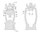
- FIG. 1shows a top view of an exemplary head/gimbal assembly (HGA) suspension according to one embodiment of the invention.
- HGAhead/gimbal assembly
- FIG. 2Ashows a top view of a metal base layer according to one embodiment of the invention.
- FIG. 2Bshows a top view of a dielectric layer according to one embodiment of the invention.
- FIG. 2Cshows a top view of a trace layer according to one embodiment of the invention.
- FIG. 2Dshows a top view of a cover layer according to one embodiment of the invention.
- FIG. 3Ashows a top view of the flexure according to one embodiment of the invention.
- FIG. 3Bshows a bottom view of the flexure according to one embodiment of the invention.
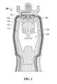
- FIG. 4shows a top view of the flexure illustrating a thinning zone section according to one embodiment of the invention.
- FIG. 5shows a perspective view of an exemplary head/gimbal assembly according to one embodiment of the invention.
- FIG. 1shows a top view of an exemplary head gimbal assembly (HGA) suspension 100 according to one embodiment of the invention.
- the HGA suspension 100comprises four layers, shown side-by-side in FIGS. 2A-2D .
- the HGA suspension 100comprises a metal base layer 110 ( FIG. 2A ), a trace layer 120 ( FIG. 2C ) disposed over the base layer 110 , a dielectric layer 130 ( FIG. 2B ) disposed between the trace layer 120 and the base layer 110 , and a cover layer 150 ( FIG. 2D ) that covers the trace layer 120 .
- cover layer 150is see-through and not shown in FIG. 1 .
- the base layer 110 , trace layer 120 , dielectric layer 130 and cover layer 150can be formed by conventional processes know in the art.
- the base layer 110comprises a metal such as stainless steel.
- the thickness of the base layer 110may be in range of about 10 ⁇ m to 25 ⁇ m, for example, 20 ⁇ m.
- the base layer 110may include two outrigger beams 200 , 204 and a first cross beam 210 disposed between the two outrigger beams 200 , 204 at a trailing end 215 of the flexure 100 and therefore also of base layer 110 .
- the base layer 110also includes a pair of second angled cross beams 220 extending from the two outrigger beams 200 and 204 , respectively.
- a flexure tongue 230extends from the pair of second angled cross beams 220 in the direction of the leading end 225 .
- the flexure tongue 230includes a slider mounting surface 235 for attaching the slider of a head to flexure 100 .
- leading end 225 and trailing end 215are used in conformity with their conventional usage in the art. In their conventional usage, these terms take their meaning from the orientation of the head as secured to the flexure 100 .
- the headmay comprise a slider and a transducer. The side of the head that includes the transducer is designated as the trailing end of the head.
- These designationsare extended to the flexure 100 , and its sub-components, such that the end of the flexure that attaches to the load beam is the leading end of the flexure 100 , while the free end of the flexure 100 is the trailing end of the flexure.
- “towards the leading end” and “towards the trailing end”designate opposing directions in the plane of the flexure 100 along a longitudinal axis thereof (see FIG. 1 ).
- a first approximately U-shaped base layer window 240is defined between the first cross beam 210 , the second pair of angled cross beams 220 , and the flexure tongue 230 .
- a second window 245defined around the flexure tongue 230 , separates the flexure tongue 230 from the two outrigger beams 200 , 204 .
- the base layer 110includes a support island 250 disposed between the two cross beams 200 and 204 and is located within the first U-shaped base layer window 240 .
- the support island 250is supported by a pair of beams 255 extending from the flexure tongue 230 .
- the support island 255is sized to fully support the trace termination pads 122 of the conductive traces 120 (see also FIG. 2C ).
- the support island 250may act as a heat sink portion to provide a heat sink during the process of forming the electrical interconnect between the trace termination pads and bonding pads of the transducer, such as during soldering.
- the trace layer 120includes a plurality of conductive traces 260 of a metal such as copper.
- a thickness of the trace layer 120is in the range of about 5 ⁇ m to 20 ⁇ m, for example, 12 ⁇ m.
- Each conductive trace 260terminates in a trace termination pad 122 , and each trace termination pad 122 has a leading edge 270 disposed closest to the flexure tongue 230 .
- the trace layer 120 including the plurality of conductive traces 260is disposed over the base layer 110 and each conductive trace 260 includes a curve section 263 that terminates in a trace termination pad 270 .
- the curve section 253 of each of the conductive traces 260extends over the U-shaped base layer window 240 of the base layer 110 .
- the dielectric layer 130may be disposed between the trace layer 120 and the base layer 110 and comprises a dielectric material such as a polyimide. In one embodiment, as will be described hereinafter, the dielectric layer 130 may be approximately 5 ⁇ m.
- the dielectric layer 130includes a portion 280 that both underlies the leading edges 270 of the trace termination pads 122 and also overlays the support island 250 , as can be seen in FIGS. 3A-3B .
- the portion 280 of the dielectric layer 130serves to electrically insulate the trace termination pads 122 from the support island 250 . Additionally, during the soldering operation that electrically connects bonding pads on a transducer of the head to the conductive traces 260 , portion 280 may prevent molten solder from wetting the underside of the trace termination pads 122 . Accordingly, in some embodiments, the portion 280 not only underlies the leading edges 270 of the trace termination path 122 but also extends beyond the leading edge 270 as can be seen in FIGS. 1-3 .
- a cover layer 150may be used to cover the trace layer 120 .
- the trace layer 150is basically see-through and thus cannot be seen in FIGS. 1 , 3 , and 4 .
- the cover layer 150may comprise a polyimide.
- the thickness of the dielectric layer 103 in the gimbal regionapproximately matches the thickness of the cover layer 150 in the gimbal region.
- the thickness of the dielectric layer 130may be approximately 5 ⁇ m and the thickness of the cover layer 150 may be approximately 5 ⁇ m.
- the thinning zone section 401is referred to as the polyimide (PI) thinning zone as these layers are thinned to match one another.
- a partially-isolated stainless steel support island 250is provided that fully supports the trace termination pads 122 of the conductive traces 120 .
- the thickness of the dielectric layer 103is configured to match the thickness of the cover layer 150 (e.g., both set at 5 ⁇ m) in the thinning zone section 402 .
- This matched thickness of the dielectric layer 130 and cover layer 150balances gimbal distortion due to temperature and humidity during assembly.
- the trace layer 120is mover approximately 5 ⁇ m closer to the stainless steel metal base layer 110 which further reduces gimbal pitch stiffness.
- pitch static angle (PSA) variationmay be minimized through the HGA assembly process including slider bonding, adhesive curing, and solder bonding.
- PSA changesmay be minimized due to different environmental conditions including both temperature and humidity changes by utilizing this new design.
- Trace pad isolation at the gimbal slider bond area and the balanced polyimide thickness of the dielectric layer 130 and cover layer 150helps to achieve these goals.
- FIG. 5shows a perspective view of the HGA 500 comprising the head 520 mounted to the HGA suspension 510 .
- the head 520includes bonding pads 530 that can be electrically connected to trace termination pads 540 by solder balls 550 .
- solder balls 550are represented as wedges, however those skilled in the art will understand that solder balls 550 assume more complex shapes as the wet the surfaces of the bonding pads 530 and the trace termination pads 540 .
- the solder balls 550comprise a solder suitable for use in solder ball bonding (SBB) or solder jet bonding (SJB) processes. Examples include tin-lead solders and lead-free equivalents such as lead-free tin solders.
- SBBsolder ball bonding
- SJBsolder jet bonding
- tin-lead solderssolder ball bonding
- lead-free equivalentssuch as lead-free tin solders.
Landscapes
- Supporting Of Heads In Record-Carrier Devices (AREA)
- Adjustment Of The Magnetic Head Position Track Following On Tapes (AREA)
Abstract
Description
Claims (24)
Priority Applications (1)
| Application Number | Priority Date | Filing Date | Title |
|---|---|---|---|
| US12/881,834US8792212B1 (en) | 2010-09-14 | 2010-09-14 | Robust gimbal design for head gimbal assembly |
Applications Claiming Priority (1)
| Application Number | Priority Date | Filing Date | Title |
|---|---|---|---|
| US12/881,834US8792212B1 (en) | 2010-09-14 | 2010-09-14 | Robust gimbal design for head gimbal assembly |
Publications (1)
| Publication Number | Publication Date |
|---|---|
| US8792212B1true US8792212B1 (en) | 2014-07-29 |
Family
ID=51212123
Family Applications (1)
| Application Number | Title | Priority Date | Filing Date |
|---|---|---|---|
| US12/881,834Active2031-08-11US8792212B1 (en) | 2010-09-14 | 2010-09-14 | Robust gimbal design for head gimbal assembly |
Country Status (1)
| Country | Link |
|---|---|
| US (1) | US8792212B1 (en) |
Cited By (41)
| Publication number | Priority date | Publication date | Assignee | Title |
|---|---|---|---|---|
| US8929180B1 (en) | 2013-04-25 | 2015-01-06 | Western Digital Technologies, Inc. | Energy-assisted magnetic recording device having laser driving signal and magnetic write signal sharing same electrical conductor |
| US8934199B1 (en) | 2014-03-31 | 2015-01-13 | Western Digital Technologies, Inc. | Disk drive head suspension tail with bond pad edge alignment features |
| US8976491B1 (en) | 2013-05-09 | 2015-03-10 | Western Digital Technologies, Inc. | Disk drive head suspension distal non-op shock limiter with branched arms |
| US9042048B1 (en) | 2014-09-30 | 2015-05-26 | Western Digital (Fremont), Llc | Laser-ignited reactive HAMR bonding |
| US9064513B1 (en) | 2014-03-07 | 2015-06-23 | Western Digital Technologies, Inc. | Disk drive suspension assembly with flexure having dual conductive layers with staggered traces |
| US9070387B1 (en) | 2013-08-23 | 2015-06-30 | Western Digital Technologies, Inc. | Integrated heat-assisted magnetic recording head/laser assembly |
| US9093102B1 (en) | 2013-03-12 | 2015-07-28 | Western Digital Technologies, Inc. | Systems and methods for tuning seed layer hardness in components of magnetic recording systems |
| US9099145B1 (en) | 2013-12-24 | 2015-08-04 | Western Digital (Fremont), Llc | High contrast alignment marker |
| US9105282B1 (en) | 2013-05-20 | 2015-08-11 | Western Digital Technologies, Inc. | Head gimbal assembly carrier with adjustable protective bar |
| US9135935B1 (en) | 2013-10-11 | 2015-09-15 | Western Digital Technologies, Inc. | Customized head gimbal assembly bonding skew angle for adjusting two-dimensional magnetic recording reader alignment |
| US9165579B1 (en) | 2014-09-26 | 2015-10-20 | Western Digital (Fremont), Llc | Air bearing area configuration for reducing flying height hump across a stroke |
| US9171562B1 (en) | 2015-03-19 | 2015-10-27 | Western Digital (Fremont), Llc | Patterned metal layer to control solder connection between laser and submount in a magnetic head |
| US9183859B1 (en) | 2014-11-11 | 2015-11-10 | Western Digital (Fremont), Llc | HAMR writer pole length characterization |
| US9190089B1 (en) | 2014-12-24 | 2015-11-17 | Western Digital (Fremont), Llc | Air bearing area configuration for contaminating particle removal |
| US9190090B1 (en) | 2014-12-24 | 2015-11-17 | Western Digital (Fremont), Llc | Multi step lube blocking air bearing area configuration |
| US9202478B1 (en) | 2015-02-10 | 2015-12-01 | Western Digital (Fremont), Llc | Method and structure for soldering a laser submount to a mounting face of a slider |
| US9230580B1 (en) | 2010-06-30 | 2016-01-05 | Western Digital Technologies, Inc. | Suspension assembly having a microactuator grounded to a flexure |
| US9242340B1 (en) | 2013-03-12 | 2016-01-26 | Western Digital Technologies, Inc. | Method to stress relieve a magnetic recording head transducer utilizing ultrasonic cavitation |
| US9257138B1 (en) | 2014-10-28 | 2016-02-09 | Western Digital (Fremont), Llc | Slider assembly and method of manufacturing same |
| US9293157B1 (en) | 2012-06-28 | 2016-03-22 | Western Digital Technologies, Inc. | Automated active feedback slice and view milling of magnetic head cross-sections |
| US9315008B1 (en) | 2013-07-16 | 2016-04-19 | Western Digital Technologies, Inc. | Method and apparatus for aligning an illumination unit to a slider for a magnetic recording device |
| US9343084B2 (en) | 2012-03-14 | 2016-05-17 | Western Digital Technologies, Inc. | Systems and methods for correcting slider parallelism error using compensation lapping |
| US9361916B1 (en) | 2014-03-13 | 2016-06-07 | Western Digital (Fremont) | Electrical lapping guide for dimensional control of back side of heat assisted magnetic recording device |
| US9368139B1 (en) | 2015-03-20 | 2016-06-14 | Western Digital (Fremont), Llc | Slider back side etching to increase shear strength between suspension and slider |
| US9372078B1 (en) | 2014-06-20 | 2016-06-21 | Western Digital (Fremont), Llc | Detecting thickness variation and quantitative depth utilizing scanning electron microscopy with a surface profiler |
| US9387568B1 (en) | 2013-02-27 | 2016-07-12 | Western Digital Technologies, Inc. | Systems and methods for correcting fabrication error in magnetic recording heads using magnetic write width measurements |
| US9431044B1 (en) | 2014-05-07 | 2016-08-30 | Western Digital (Fremont), Llc | Slider having shock and particle resistance |
| US9431037B2 (en) | 2013-03-12 | 2016-08-30 | Western Digitatl (Fremont), LLC | Systems and methods for monitoring the power of a light source utilized in energy-assisted magnetic recording |
| US9659589B2 (en) | 2015-09-29 | 2017-05-23 | Western Digital (Fremont), Llc | Free-standing reflector usable in heat assisted magnetic recording technology |
| US9659587B1 (en) | 2015-11-06 | 2017-05-23 | Western Digital (Fremont), Llc | Magnetic head having a reader overcoat with DLC and a recessed writer overcoat without DLC |
| US9685187B1 (en) | 2014-09-26 | 2017-06-20 | Western Digital (Fremont), Llc | Bonding tool and method for high accuracy chip-to-chip bonding |
| US9805748B1 (en) | 2014-06-24 | 2017-10-31 | Western Digital (Fremont), Llc | System and method for providing a protective layer having a graded intermediate layer |
| US9870788B2 (en) | 2014-01-08 | 2018-01-16 | Western Digital (Fremont), Llc | Method of adjusting tilt using magnetic erase width feedback |
| US11069375B1 (en) | 2020-05-27 | 2021-07-20 | Western Digital Technologies, Inc. | Suspension standoff arrangement for confining adhesive |
| US11081130B1 (en) | 2020-01-31 | 2021-08-03 | Western Digital Technologies, Inc. | Suspension standoff arrangement for confining adhesive |
| US20220262395A1 (en)* | 2021-02-17 | 2022-08-18 | Magnecomp Corporation | Hard Disk Drive Gimbal Design with High Yaw Mode |
| US20220310116A1 (en)* | 2021-03-26 | 2022-09-29 | Magnecomp Corporation | Hard Disk Drive Gimbal Design With High Torsion Frequencies |
| JP2023512245A (en)* | 2020-01-31 | 2023-03-24 | マグネコンプ コーポレーション | suspension damping |
| US11631426B1 (en)* | 2021-12-15 | 2023-04-18 | Western Digital Technologies, Inc. | Hard disk drive suspension pad peel-prevention configuration |
| US11705153B1 (en) | 2022-03-23 | 2023-07-18 | Western Digital Technologies, Inc. | Hard disk drive suspension pad pre-solder formation and guiding |
| US12367899B2 (en) | 2020-10-20 | 2025-07-22 | Magnecomp Corporation | Gimbal strut configuration for high yaw suspension design |
Citations (58)
| Publication number | Priority date | Publication date | Assignee | Title |
|---|---|---|---|---|
| US5870258A (en) | 1996-02-12 | 1999-02-09 | Read-Rite Corporation | Conductive trace flexure for a magnetic head suspension assembly |
| US5883758A (en) | 1996-08-07 | 1999-03-16 | Hutchinson Technology Incorporated | Lead structure with stainless steel base for attachment to a suspension |
| US5956212A (en) | 1997-12-29 | 1999-09-21 | Headway Technologies, Inc. | Static attitude adjustment of a trace-suspension assembly |
| US5959807A (en) | 1996-06-24 | 1999-09-28 | Hutchinson Technology, Inc. | Head suspension with motion restraining tethers |
| US6249404B1 (en) | 1999-02-04 | 2001-06-19 | Read-Rite Corporation | Head gimbal assembly with a flexible printed circuit having a serpentine substrate |
| US6320730B1 (en) | 1998-09-26 | 2001-11-20 | Seagate Technology Llc | Low-stress disc drive microactuator cradle |
| US6351354B1 (en) | 1999-05-07 | 2002-02-26 | Seagate Technology Llc | Head to flexure interconnection for disc drive microactuator |
| US6421211B1 (en) | 1999-10-20 | 2002-07-16 | Read-Rite Corporation | Disk drive actuator arm with microactuated read/write head positioning |
| US6459549B1 (en) | 1999-07-15 | 2002-10-01 | International Business Machines Corporation | Hard disk drive with slider support structure and head gimbal assembly |
| US6515832B1 (en) | 2000-04-19 | 2003-02-04 | Applied Kinetics, Inc. | Gimbal stiffness control for head suspension assemblies |
| US6661619B2 (en) | 2000-12-15 | 2003-12-09 | Nhk Spring Co., Ltd. | Suspension for disc drive |
| US20040226164A1 (en) | 2001-03-09 | 2004-11-18 | Applied Kinetics, Inc. | Method and apparatus for improved static attitude of head suspension assemblies with electrical interconnects |
| US20040246625A1 (en)* | 2003-04-23 | 2004-12-09 | Hitachi Global Storage Technologies Netherlands, B.V. | Suspension assembly and rotary disk storage device |
| US20050047019A1 (en) | 2003-08-28 | 2005-03-03 | Hitachi Global Storage Technologies Netherlands B.V. | Disk drive with controlled pitch static attitude of sliders on integrated lead suspensions by improved plastic deformation processing |
| US6870709B2 (en) | 2001-11-16 | 2005-03-22 | Fujitsu Limited | Head slider having piezoelectric actuator |
| US20050117257A1 (en) | 2003-12-01 | 2005-06-02 | Kr Precision Public Company Limited | Method to form electrostatic discharge protection on flexible circuits |
| US6965499B1 (en) | 2002-04-25 | 2005-11-15 | Hutchinson Technology Incorporated | Head suspension configured for improved thermal performance during solder ball bonding to head slider |
| US6993824B2 (en) | 2003-08-28 | 2006-02-07 | Hitachi Global Storage Technologies Netherlands B.V. | Method of controlling pitch static attitude of sliders on integrated lead suspensions by improved plastic deformation processing |
| US7002780B2 (en) | 2000-11-01 | 2006-02-21 | Seagate Technology Llc | Suspension design for elevated slider attachment |
| US7006330B1 (en) | 2003-03-10 | 2006-02-28 | Western Digital Technologies, Inc. | Head stack assembly including a ground conductive pad for grounding a slider to a gimbal |
| US7006331B1 (en) | 2003-09-30 | 2006-02-28 | Western Digital Technologies, Inc. | Head gimbal assembly including a trace suspension assembly backing layer with a conductive layer formed upon a gimbal having a lower oxidation rate |
| US7023663B2 (en) | 2001-11-03 | 2006-04-04 | Sae Magnetice (H.K.) Ltd. | Method and apparatus for improved attachment of a micro-actuator to a slider device |
| US7113372B2 (en) | 2001-11-09 | 2006-09-26 | Seagate Technology Llc | HGA plateau gimbal design |
| US20060262456A1 (en) | 2005-05-17 | 2006-11-23 | Wang Jeffery L | Gimbal design with solder ball bond pads and trailing edge limiter tab for a recording head |
| US7159300B2 (en) | 2002-08-26 | 2007-01-09 | Sae Magnetics (H.K.) Ltd. | Method for manufacturing a suspension design for a co-located PZT micro-actuator |
| US20070263325A1 (en) | 2006-05-10 | 2007-11-15 | Nhk Spring Co., Ltd. | Slider supporting apparatus and manufacturing method therefor |
| US7301731B2 (en) | 2002-06-18 | 2007-11-27 | Fujitsu Limited | Head assembly having microactuator |
| US20080030900A1 (en) | 2006-08-01 | 2008-02-07 | Sae Magnetics (Hk) Ltd. | Suspension gimbal designs with better dynamic performances |
| US7345851B2 (en) | 2004-08-26 | 2008-03-18 | Hitachi Global Storage Technologies Netherlands B.V. | Disk drive with rotary piezoelectric microactuator |
| US7382583B2 (en) | 2004-08-26 | 2008-06-03 | Hitachi Global Storage Technologies Netherlands B.V. | Rotary piezoelectric microactuator and disk drive head-suspension assembly |
| US20080144225A1 (en) | 2006-12-14 | 2008-06-19 | Sae Magnetics (H.K.) Ltd. | Techniques for reducing flexure distortion and gimbal separation for thin-film PZT micro-actuators of head gimbal assemblies |
| US20080144223A1 (en)* | 2006-12-14 | 2008-06-19 | Hitachi Global Storage Technologies Netherlands B. V. | Magnetic disk drive and suspension assembly adopted therein |
| US7403357B1 (en) | 2004-08-05 | 2008-07-22 | Maxtor Corporation | Disk drive flexure assembly with a plurality of support bond pad apertures with a bond pad disposed over a bond pad support and part of each support bond pad aperture |
| US20080180850A1 (en) | 2007-01-26 | 2008-07-31 | Hutchinson Technology Incorporated | Head suspension flexure with inline lead portions |
| US7411764B2 (en) | 2005-09-30 | 2008-08-12 | Sae Magnetics (H.K.) Ltd. | Head gimbal assembly with precise positioning actuator for read/write head and disk drive device with the head gimbal assembly |
| US7417831B2 (en) | 2005-11-03 | 2008-08-26 | Sae Magnetics (H.K.) Ltd. | Micro-actuator and head gimbal assembly for a disk drive device |
| US7466520B2 (en) | 2004-10-07 | 2008-12-16 | Seagate Technology Llc | Co-located microactuator lever assembly |
| US7471490B2 (en) | 2006-03-21 | 2008-12-30 | Sae Magnetics (H.K.) Ltd. | Micro-actuator including U-shaped frame and metal support frame, and manufacturing method thereof |
| US7474512B2 (en) | 2005-12-15 | 2009-01-06 | Sae Magnetics (H.K.) Ltd. | Miro-actuator, head gimbal assembly, and disk drive unit with the same |
| US20090080116A1 (en) | 2007-09-19 | 2009-03-26 | Haruhide Takahashi | Microactuator,head gimbal assembly, and magnetic disk drive |
| US7525769B2 (en) | 2003-11-27 | 2009-04-28 | Sae Magnetics (H.K.) Ltd. | Micro-actuator having swing support to allow horizontal swinging movement of slider support |
| US7535680B2 (en) | 2005-06-29 | 2009-05-19 | Sae Magnetics (H.K.) Ltd. | Micro-actuator with integrated trace and bonding pad support |
| US7538984B2 (en) | 2005-12-16 | 2009-05-26 | Sae Magnetics (H.K.) Ltd. | Rotational PZT micro-actuator with a rotatable plate |
| US7545605B2 (en) | 2005-06-15 | 2009-06-09 | Hitachi Global Storage Technologies Netherlands B.V. | Method for reducing PSA tilt through standoff relocation |
| US7554773B2 (en) | 2005-02-28 | 2009-06-30 | Sae Magnetics (H.K.) Ltd. | Micro-actuator, head gimbal assembly and disk drive unit with the same |
| US7567410B1 (en)* | 2006-10-31 | 2009-07-28 | Western Digital Technologies, Inc. | Flexure including a heat sink and a dielectric layer under trace termination pads |
| US7593190B1 (en) | 2001-12-21 | 2009-09-22 | Western Digital (Fremont), Llc | Flexure design and assembly process for attachment of slider using solder and laser reflow |
| US7609487B2 (en) | 2005-11-16 | 2009-10-27 | Sae Magnetics (H.K.) Ltd. | Thin-film PZT micro-actuator integral with suspension of head gimbal assembly, and disk drive unit with the same |
| US7663843B2 (en) | 2005-11-02 | 2010-02-16 | Sae Magnetics (H.K.) Ltd. | Flex cable frame assembly for micro-actuator and flex cable suspension assembly for HGA of disk drive device |
| US7688553B1 (en) | 2004-08-05 | 2010-03-30 | Seagate Technology Llc | Thermally-compensating attachment of disk drive slider to flexure |
| US7697237B1 (en) | 2007-01-11 | 2010-04-13 | Hutchinson Technology Incorporated | Shielded copper-dielectric flexure for disk drive head suspensions |
| US7701675B2 (en) | 2005-12-16 | 2010-04-20 | Sae Magnetics (H.K.) Ltd. | Micro-actuator mounting structure capable of maintaining a substantially constant gap between a top support of a micro-actuator and a suspension during use |
| US7719798B2 (en) | 2006-02-14 | 2010-05-18 | Sae Magnetics (H.K.) Ltd. | Rotational micro-actuator integrated with suspension of head gimbal assembly, and disk drive unit with the same |
| US7733607B2 (en) | 2006-03-24 | 2010-06-08 | Sae Magnetics (H.K.) Ltd. | Suspension with strengthening plate, head gimbal assembly, and disk drive unit with the same |
| US8027128B2 (en)* | 2008-04-21 | 2011-09-27 | Hitachi Global Storage Technologies, Netherlands, B.V. | Suspension and disk drive |
| US8054585B2 (en) | 2006-11-28 | 2011-11-08 | Sae Magnetics (Hk) Ltd. | Gimbal with assymmetric dynamic stiffness |
| US8208224B1 (en) | 2011-08-29 | 2012-06-26 | Western Digital Technologies, Inc. | Suspension assemblies for minimizing stress on slider solder joints |
| US8605389B1 (en) | 2006-06-09 | 2013-12-10 | Western Digital Technologies, Inc. | Head gimbal assembly including a conductive trace disposed upon a continuous dielectric layer segment without overlying a gimbal arm |
- 2010
- 2010-09-14USUS12/881,834patent/US8792212B1/enactiveActive
Patent Citations (60)
| Publication number | Priority date | Publication date | Assignee | Title |
|---|---|---|---|---|
| US5870258A (en) | 1996-02-12 | 1999-02-09 | Read-Rite Corporation | Conductive trace flexure for a magnetic head suspension assembly |
| US5959807A (en) | 1996-06-24 | 1999-09-28 | Hutchinson Technology, Inc. | Head suspension with motion restraining tethers |
| US5883758A (en) | 1996-08-07 | 1999-03-16 | Hutchinson Technology Incorporated | Lead structure with stainless steel base for attachment to a suspension |
| US5956212A (en) | 1997-12-29 | 1999-09-21 | Headway Technologies, Inc. | Static attitude adjustment of a trace-suspension assembly |
| US6320730B1 (en) | 1998-09-26 | 2001-11-20 | Seagate Technology Llc | Low-stress disc drive microactuator cradle |
| US6249404B1 (en) | 1999-02-04 | 2001-06-19 | Read-Rite Corporation | Head gimbal assembly with a flexible printed circuit having a serpentine substrate |
| US6351354B1 (en) | 1999-05-07 | 2002-02-26 | Seagate Technology Llc | Head to flexure interconnection for disc drive microactuator |
| US6459549B1 (en) | 1999-07-15 | 2002-10-01 | International Business Machines Corporation | Hard disk drive with slider support structure and head gimbal assembly |
| US6421211B1 (en) | 1999-10-20 | 2002-07-16 | Read-Rite Corporation | Disk drive actuator arm with microactuated read/write head positioning |
| US6515832B1 (en) | 2000-04-19 | 2003-02-04 | Applied Kinetics, Inc. | Gimbal stiffness control for head suspension assemblies |
| US7002780B2 (en) | 2000-11-01 | 2006-02-21 | Seagate Technology Llc | Suspension design for elevated slider attachment |
| US6661619B2 (en) | 2000-12-15 | 2003-12-09 | Nhk Spring Co., Ltd. | Suspension for disc drive |
| US20040226164A1 (en) | 2001-03-09 | 2004-11-18 | Applied Kinetics, Inc. | Method and apparatus for improved static attitude of head suspension assemblies with electrical interconnects |
| US7023663B2 (en) | 2001-11-03 | 2006-04-04 | Sae Magnetice (H.K.) Ltd. | Method and apparatus for improved attachment of a micro-actuator to a slider device |
| US7113372B2 (en) | 2001-11-09 | 2006-09-26 | Seagate Technology Llc | HGA plateau gimbal design |
| US6870709B2 (en) | 2001-11-16 | 2005-03-22 | Fujitsu Limited | Head slider having piezoelectric actuator |
| US7593190B1 (en) | 2001-12-21 | 2009-09-22 | Western Digital (Fremont), Llc | Flexure design and assembly process for attachment of slider using solder and laser reflow |
| US6965499B1 (en) | 2002-04-25 | 2005-11-15 | Hutchinson Technology Incorporated | Head suspension configured for improved thermal performance during solder ball bonding to head slider |
| US7301731B2 (en) | 2002-06-18 | 2007-11-27 | Fujitsu Limited | Head assembly having microactuator |
| US7159300B2 (en) | 2002-08-26 | 2007-01-09 | Sae Magnetics (H.K.) Ltd. | Method for manufacturing a suspension design for a co-located PZT micro-actuator |
| US7006330B1 (en) | 2003-03-10 | 2006-02-28 | Western Digital Technologies, Inc. | Head stack assembly including a ground conductive pad for grounding a slider to a gimbal |
| US20040246625A1 (en)* | 2003-04-23 | 2004-12-09 | Hitachi Global Storage Technologies Netherlands, B.V. | Suspension assembly and rotary disk storage device |
| US20050047019A1 (en) | 2003-08-28 | 2005-03-03 | Hitachi Global Storage Technologies Netherlands B.V. | Disk drive with controlled pitch static attitude of sliders on integrated lead suspensions by improved plastic deformation processing |
| US6993824B2 (en) | 2003-08-28 | 2006-02-07 | Hitachi Global Storage Technologies Netherlands B.V. | Method of controlling pitch static attitude of sliders on integrated lead suspensions by improved plastic deformation processing |
| US7006331B1 (en) | 2003-09-30 | 2006-02-28 | Western Digital Technologies, Inc. | Head gimbal assembly including a trace suspension assembly backing layer with a conductive layer formed upon a gimbal having a lower oxidation rate |
| US7525769B2 (en) | 2003-11-27 | 2009-04-28 | Sae Magnetics (H.K.) Ltd. | Micro-actuator having swing support to allow horizontal swinging movement of slider support |
| US20050117257A1 (en) | 2003-12-01 | 2005-06-02 | Kr Precision Public Company Limited | Method to form electrostatic discharge protection on flexible circuits |
| US7688553B1 (en) | 2004-08-05 | 2010-03-30 | Seagate Technology Llc | Thermally-compensating attachment of disk drive slider to flexure |
| US7403357B1 (en) | 2004-08-05 | 2008-07-22 | Maxtor Corporation | Disk drive flexure assembly with a plurality of support bond pad apertures with a bond pad disposed over a bond pad support and part of each support bond pad aperture |
| US7345851B2 (en) | 2004-08-26 | 2008-03-18 | Hitachi Global Storage Technologies Netherlands B.V. | Disk drive with rotary piezoelectric microactuator |
| US7382583B2 (en) | 2004-08-26 | 2008-06-03 | Hitachi Global Storage Technologies Netherlands B.V. | Rotary piezoelectric microactuator and disk drive head-suspension assembly |
| US7466520B2 (en) | 2004-10-07 | 2008-12-16 | Seagate Technology Llc | Co-located microactuator lever assembly |
| US7554773B2 (en) | 2005-02-28 | 2009-06-30 | Sae Magnetics (H.K.) Ltd. | Micro-actuator, head gimbal assembly and disk drive unit with the same |
| US20060262456A1 (en) | 2005-05-17 | 2006-11-23 | Wang Jeffery L | Gimbal design with solder ball bond pads and trailing edge limiter tab for a recording head |
| US7545605B2 (en) | 2005-06-15 | 2009-06-09 | Hitachi Global Storage Technologies Netherlands B.V. | Method for reducing PSA tilt through standoff relocation |
| US7535680B2 (en) | 2005-06-29 | 2009-05-19 | Sae Magnetics (H.K.) Ltd. | Micro-actuator with integrated trace and bonding pad support |
| US7411764B2 (en) | 2005-09-30 | 2008-08-12 | Sae Magnetics (H.K.) Ltd. | Head gimbal assembly with precise positioning actuator for read/write head and disk drive device with the head gimbal assembly |
| US7663843B2 (en) | 2005-11-02 | 2010-02-16 | Sae Magnetics (H.K.) Ltd. | Flex cable frame assembly for micro-actuator and flex cable suspension assembly for HGA of disk drive device |
| US7417831B2 (en) | 2005-11-03 | 2008-08-26 | Sae Magnetics (H.K.) Ltd. | Micro-actuator and head gimbal assembly for a disk drive device |
| US7609487B2 (en) | 2005-11-16 | 2009-10-27 | Sae Magnetics (H.K.) Ltd. | Thin-film PZT micro-actuator integral with suspension of head gimbal assembly, and disk drive unit with the same |
| US7474512B2 (en) | 2005-12-15 | 2009-01-06 | Sae Magnetics (H.K.) Ltd. | Miro-actuator, head gimbal assembly, and disk drive unit with the same |
| US7701675B2 (en) | 2005-12-16 | 2010-04-20 | Sae Magnetics (H.K.) Ltd. | Micro-actuator mounting structure capable of maintaining a substantially constant gap between a top support of a micro-actuator and a suspension during use |
| US7538984B2 (en) | 2005-12-16 | 2009-05-26 | Sae Magnetics (H.K.) Ltd. | Rotational PZT micro-actuator with a rotatable plate |
| US7719798B2 (en) | 2006-02-14 | 2010-05-18 | Sae Magnetics (H.K.) Ltd. | Rotational micro-actuator integrated with suspension of head gimbal assembly, and disk drive unit with the same |
| US7471490B2 (en) | 2006-03-21 | 2008-12-30 | Sae Magnetics (H.K.) Ltd. | Micro-actuator including U-shaped frame and metal support frame, and manufacturing method thereof |
| US7733607B2 (en) | 2006-03-24 | 2010-06-08 | Sae Magnetics (H.K.) Ltd. | Suspension with strengthening plate, head gimbal assembly, and disk drive unit with the same |
| US20070263325A1 (en) | 2006-05-10 | 2007-11-15 | Nhk Spring Co., Ltd. | Slider supporting apparatus and manufacturing method therefor |
| US8605389B1 (en) | 2006-06-09 | 2013-12-10 | Western Digital Technologies, Inc. | Head gimbal assembly including a conductive trace disposed upon a continuous dielectric layer segment without overlying a gimbal arm |
| US20080030900A1 (en) | 2006-08-01 | 2008-02-07 | Sae Magnetics (Hk) Ltd. | Suspension gimbal designs with better dynamic performances |
| US7567410B1 (en)* | 2006-10-31 | 2009-07-28 | Western Digital Technologies, Inc. | Flexure including a heat sink and a dielectric layer under trace termination pads |
| US8054585B2 (en) | 2006-11-28 | 2011-11-08 | Sae Magnetics (Hk) Ltd. | Gimbal with assymmetric dynamic stiffness |
| US20080144225A1 (en) | 2006-12-14 | 2008-06-19 | Sae Magnetics (H.K.) Ltd. | Techniques for reducing flexure distortion and gimbal separation for thin-film PZT micro-actuators of head gimbal assemblies |
| US8130470B2 (en)* | 2006-12-14 | 2012-03-06 | Hitachi Global Storage Technologies, Netherlands B.V. | Suspension assembly including a limiter having a gross length larger than a between-coupling-portions distance between coupling portions |
| US20080144223A1 (en)* | 2006-12-14 | 2008-06-19 | Hitachi Global Storage Technologies Netherlands B. V. | Magnetic disk drive and suspension assembly adopted therein |
| US7697237B1 (en) | 2007-01-11 | 2010-04-13 | Hutchinson Technology Incorporated | Shielded copper-dielectric flexure for disk drive head suspensions |
| US20080180850A1 (en) | 2007-01-26 | 2008-07-31 | Hutchinson Technology Incorporated | Head suspension flexure with inline lead portions |
| US7813082B2 (en) | 2007-01-26 | 2010-10-12 | Hutchinson Technology Incorporated | Head suspension flexure with inline lead portions positioned at a level between levels of first and second surfaces of the spring metal layer |
| US20090080116A1 (en) | 2007-09-19 | 2009-03-26 | Haruhide Takahashi | Microactuator,head gimbal assembly, and magnetic disk drive |
| US8027128B2 (en)* | 2008-04-21 | 2011-09-27 | Hitachi Global Storage Technologies, Netherlands, B.V. | Suspension and disk drive |
| US8208224B1 (en) | 2011-08-29 | 2012-06-26 | Western Digital Technologies, Inc. | Suspension assemblies for minimizing stress on slider solder joints |
Cited By (47)
| Publication number | Priority date | Publication date | Assignee | Title |
|---|---|---|---|---|
| US9230580B1 (en) | 2010-06-30 | 2016-01-05 | Western Digital Technologies, Inc. | Suspension assembly having a microactuator grounded to a flexure |
| US9343084B2 (en) | 2012-03-14 | 2016-05-17 | Western Digital Technologies, Inc. | Systems and methods for correcting slider parallelism error using compensation lapping |
| US9293157B1 (en) | 2012-06-28 | 2016-03-22 | Western Digital Technologies, Inc. | Automated active feedback slice and view milling of magnetic head cross-sections |
| US9387568B1 (en) | 2013-02-27 | 2016-07-12 | Western Digital Technologies, Inc. | Systems and methods for correcting fabrication error in magnetic recording heads using magnetic write width measurements |
| US9431037B2 (en) | 2013-03-12 | 2016-08-30 | Western Digitatl (Fremont), LLC | Systems and methods for monitoring the power of a light source utilized in energy-assisted magnetic recording |
| US9449631B2 (en) | 2013-03-12 | 2016-09-20 | Western Digital Technologies, Inc. | Slider for magnetic recording system |
| US9093102B1 (en) | 2013-03-12 | 2015-07-28 | Western Digital Technologies, Inc. | Systems and methods for tuning seed layer hardness in components of magnetic recording systems |
| US9242340B1 (en) | 2013-03-12 | 2016-01-26 | Western Digital Technologies, Inc. | Method to stress relieve a magnetic recording head transducer utilizing ultrasonic cavitation |
| US8929180B1 (en) | 2013-04-25 | 2015-01-06 | Western Digital Technologies, Inc. | Energy-assisted magnetic recording device having laser driving signal and magnetic write signal sharing same electrical conductor |
| US8976491B1 (en) | 2013-05-09 | 2015-03-10 | Western Digital Technologies, Inc. | Disk drive head suspension distal non-op shock limiter with branched arms |
| US9105282B1 (en) | 2013-05-20 | 2015-08-11 | Western Digital Technologies, Inc. | Head gimbal assembly carrier with adjustable protective bar |
| US9315008B1 (en) | 2013-07-16 | 2016-04-19 | Western Digital Technologies, Inc. | Method and apparatus for aligning an illumination unit to a slider for a magnetic recording device |
| US9070387B1 (en) | 2013-08-23 | 2015-06-30 | Western Digital Technologies, Inc. | Integrated heat-assisted magnetic recording head/laser assembly |
| US9135935B1 (en) | 2013-10-11 | 2015-09-15 | Western Digital Technologies, Inc. | Customized head gimbal assembly bonding skew angle for adjusting two-dimensional magnetic recording reader alignment |
| US9099145B1 (en) | 2013-12-24 | 2015-08-04 | Western Digital (Fremont), Llc | High contrast alignment marker |
| US9870788B2 (en) | 2014-01-08 | 2018-01-16 | Western Digital (Fremont), Llc | Method of adjusting tilt using magnetic erase width feedback |
| US9064513B1 (en) | 2014-03-07 | 2015-06-23 | Western Digital Technologies, Inc. | Disk drive suspension assembly with flexure having dual conductive layers with staggered traces |
| US9361916B1 (en) | 2014-03-13 | 2016-06-07 | Western Digital (Fremont) | Electrical lapping guide for dimensional control of back side of heat assisted magnetic recording device |
| US8934199B1 (en) | 2014-03-31 | 2015-01-13 | Western Digital Technologies, Inc. | Disk drive head suspension tail with bond pad edge alignment features |
| US9431044B1 (en) | 2014-05-07 | 2016-08-30 | Western Digital (Fremont), Llc | Slider having shock and particle resistance |
| US9372078B1 (en) | 2014-06-20 | 2016-06-21 | Western Digital (Fremont), Llc | Detecting thickness variation and quantitative depth utilizing scanning electron microscopy with a surface profiler |
| US9805748B1 (en) | 2014-06-24 | 2017-10-31 | Western Digital (Fremont), Llc | System and method for providing a protective layer having a graded intermediate layer |
| US9685187B1 (en) | 2014-09-26 | 2017-06-20 | Western Digital (Fremont), Llc | Bonding tool and method for high accuracy chip-to-chip bonding |
| US9165579B1 (en) | 2014-09-26 | 2015-10-20 | Western Digital (Fremont), Llc | Air bearing area configuration for reducing flying height hump across a stroke |
| US9042048B1 (en) | 2014-09-30 | 2015-05-26 | Western Digital (Fremont), Llc | Laser-ignited reactive HAMR bonding |
| US9257138B1 (en) | 2014-10-28 | 2016-02-09 | Western Digital (Fremont), Llc | Slider assembly and method of manufacturing same |
| US9183859B1 (en) | 2014-11-11 | 2015-11-10 | Western Digital (Fremont), Llc | HAMR writer pole length characterization |
| US9190090B1 (en) | 2014-12-24 | 2015-11-17 | Western Digital (Fremont), Llc | Multi step lube blocking air bearing area configuration |
| US9190089B1 (en) | 2014-12-24 | 2015-11-17 | Western Digital (Fremont), Llc | Air bearing area configuration for contaminating particle removal |
| US9202478B1 (en) | 2015-02-10 | 2015-12-01 | Western Digital (Fremont), Llc | Method and structure for soldering a laser submount to a mounting face of a slider |
| US9171562B1 (en) | 2015-03-19 | 2015-10-27 | Western Digital (Fremont), Llc | Patterned metal layer to control solder connection between laser and submount in a magnetic head |
| US9368139B1 (en) | 2015-03-20 | 2016-06-14 | Western Digital (Fremont), Llc | Slider back side etching to increase shear strength between suspension and slider |
| US9659589B2 (en) | 2015-09-29 | 2017-05-23 | Western Digital (Fremont), Llc | Free-standing reflector usable in heat assisted magnetic recording technology |
| US9659587B1 (en) | 2015-11-06 | 2017-05-23 | Western Digital (Fremont), Llc | Magnetic head having a reader overcoat with DLC and a recessed writer overcoat without DLC |
| US12002497B2 (en)* | 2020-01-31 | 2024-06-04 | Magnecomp Corporation | Suspension damping |
| US11081130B1 (en) | 2020-01-31 | 2021-08-03 | Western Digital Technologies, Inc. | Suspension standoff arrangement for confining adhesive |
| JP2023512245A (en)* | 2020-01-31 | 2023-03-24 | マグネコンプ コーポレーション | suspension damping |
| US12387752B2 (en) | 2020-01-31 | 2025-08-12 | Magnecomp Corporation | Suspension damping |
| US11069375B1 (en) | 2020-05-27 | 2021-07-20 | Western Digital Technologies, Inc. | Suspension standoff arrangement for confining adhesive |
| US12367899B2 (en) | 2020-10-20 | 2025-07-22 | Magnecomp Corporation | Gimbal strut configuration for high yaw suspension design |
| US20220262395A1 (en)* | 2021-02-17 | 2022-08-18 | Magnecomp Corporation | Hard Disk Drive Gimbal Design with High Yaw Mode |
| US11688421B2 (en)* | 2021-02-17 | 2023-06-27 | Magnecomp Corporation | Hard disk drive gimbal design with high yaw mode |
| US20220310116A1 (en)* | 2021-03-26 | 2022-09-29 | Magnecomp Corporation | Hard Disk Drive Gimbal Design With High Torsion Frequencies |
| US11715490B2 (en)* | 2021-03-26 | 2023-08-01 | Magnecomp Corporation | Hard disk drive gimbal design with high torsion frequencies |
| US12300281B2 (en) | 2021-03-26 | 2025-05-13 | Magnecomp Corporation | Hard disk drive gimbal design with high torsion frequencies |
| US11631426B1 (en)* | 2021-12-15 | 2023-04-18 | Western Digital Technologies, Inc. | Hard disk drive suspension pad peel-prevention configuration |
| US11705153B1 (en) | 2022-03-23 | 2023-07-18 | Western Digital Technologies, Inc. | Hard disk drive suspension pad pre-solder formation and guiding |
Similar Documents
| Publication | Publication Date | Title |
|---|---|---|
| US8792212B1 (en) | Robust gimbal design for head gimbal assembly | |
| US7567410B1 (en) | Flexure including a heat sink and a dielectric layer under trace termination pads | |
| US8780504B1 (en) | Disk drive head suspension assembly with load beam inner rails between piezo actuator elements | |
| US7372669B2 (en) | Magnetic disk drive, wiring connection structure and terminal structure | |
| US8792213B1 (en) | Tethered gimbal on suspension for improved flyability | |
| US7777991B2 (en) | Head gimbal assembly with improved interconnection between head slider and suspension, fabricating method thereof, and magnetic disk drive with the same | |
| US7391594B2 (en) | Apparatus for providing an additional ground pad and electrical connection for grounding a magnetic recording head | |
| US8295013B1 (en) | Disk drive head stack assembly having a flexible printed circuit with heat transfer limiting features | |
| US10373635B2 (en) | Magnetic head suspension assembly having flexible wiring member with connection terminal including center hole and cover layer and disk device provided with the same | |
| US8941952B1 (en) | Disk drive head stack assembly having a flexible printed circuit with bond pads having reduced capacitance | |
| US10381028B2 (en) | Circuit member of disk drive suspension | |
| US9514773B2 (en) | Head stack assembly with a flexible printed circuit having a mouth centered between arms | |
| US6417997B1 (en) | Mechanically formed standoffs in a circuit interconnect | |
| US9953667B2 (en) | Disk drive system | |
| US10388309B2 (en) | Circuit member of disk drive suspension having a metal base and a side pad portion electrically insulated from the metal base | |
| CN105976834A (en) | Suspension assembly, head suspension assembly and disk device with the same | |
| CN101206868B (en) | Improved magnetic head tabs combination and its manufacturing method and disk drive unit | |
| US11670328B2 (en) | Disk-drive suspension, electronic component, and connection method of suspension and electronic component | |
| US8472142B2 (en) | Method of making a bonded structure for an electrical component, and/or head gimbal assembly, head stack assembly, and disk drive unit incorporating the same | |
| US9496625B2 (en) | Terminal connection structure with elevated terminals | |
| JP4106315B2 (en) | Low cost head and gimbal assembly | |
| US7542242B2 (en) | FPC with via holes with filler being welded to suspension and drive apparatus | |
| JP5974824B2 (en) | Suspension substrate, suspension, suspension with head, hard disk drive, and method for manufacturing suspension substrate | |
| US20050141138A1 (en) | Suspension, head gimbal assembly and disk drive apparatus with head gimbal assembly | |
| US9564156B1 (en) | Head gimbal assembly having a flexure tail with cover layer standoff islands |
Legal Events
| Date | Code | Title | Description |
|---|---|---|---|
| AS | Assignment | Owner name:WESTERN DIGITAL (FREMONT), LLC, CALIFORNIA Free format text:ASSIGNMENT OF ASSIGNORS INTEREST;ASSIGNORS:PAN, TZONG-SHII;PETDEE, THEERAWAT;REEL/FRAME:025391/0079 Effective date:20100915 | |
| STCF | Information on status: patent grant | Free format text:PATENTED CASE | |
| AS | Assignment | Owner name:JPMORGAN CHASE BANK, N.A., AS COLLATERAL AGENT, IL Free format text:SECURITY AGREEMENT;ASSIGNOR:WESTERN DIGITAL (FREMONT), LLC;REEL/FRAME:038710/0845 Effective date:20160512 Owner name:U.S. BANK NATIONAL ASSOCIATION, AS COLLATERAL AGEN Free format text:SECURITY AGREEMENT;ASSIGNOR:WESTERN DIGITAL (FREMONT), LLC;REEL/FRAME:038744/0675 Effective date:20160512 Owner name:JPMORGAN CHASE BANK, N.A., AS COLLATERAL AGENT, IL Free format text:SECURITY AGREEMENT;ASSIGNOR:WESTERN DIGITAL (FREMONT), LLC;REEL/FRAME:038744/0755 Effective date:20160512 | |
| MAFP | Maintenance fee payment | Free format text:PAYMENT OF MAINTENANCE FEE, 4TH YEAR, LARGE ENTITY (ORIGINAL EVENT CODE: M1551) Year of fee payment:4 | |
| AS | Assignment | Owner name:WESTERN DIGITAL (FREMONT), LLC, CALIFORNIA Free format text:RELEASE BY SECURED PARTY;ASSIGNOR:U.S. BANK NATIONAL ASSOCIATION, AS COLLATERAL AGENT;REEL/FRAME:045501/0158 Effective date:20180227 | |
| AS | Assignment | Owner name:WESTERN DIGITAL TECHNOLOGIES, INC., CALIFORNIA Free format text:ASSIGNMENT OF ASSIGNORS INTEREST;ASSIGNOR:WESTERN DIGITAL (FREMONT), LLC;REEL/FRAME:050450/0582 Effective date:20190508 | |
| MAFP | Maintenance fee payment | Free format text:PAYMENT OF MAINTENANCE FEE, 8TH YEAR, LARGE ENTITY (ORIGINAL EVENT CODE: M1552); ENTITY STATUS OF PATENT OWNER: LARGE ENTITY Year of fee payment:8 | |
| AS | Assignment | Owner name:WESTERN DIGITAL TECHNOLOGIES, INC., CALIFORNIA Free format text:RELEASE OF SECURITY INTEREST AT REEL 038710 FRAME 0845;ASSIGNOR:JPMORGAN CHASE BANK, N.A.;REEL/FRAME:058965/0445 Effective date:20220203 Owner name:WESTERN DIGITAL (FREMONT), LLC, CALIFORNIA Free format text:RELEASE OF SECURITY INTEREST AT REEL 038710 FRAME 0845;ASSIGNOR:JPMORGAN CHASE BANK, N.A.;REEL/FRAME:058965/0445 Effective date:20220203 | |
| AS | Assignment | Owner name:JPMORGAN CHASE BANK, N.A., ILLINOIS Free format text:PATENT COLLATERAL AGREEMENT - A&R LOAN AGREEMENT;ASSIGNOR:WESTERN DIGITAL TECHNOLOGIES, INC.;REEL/FRAME:064715/0001 Effective date:20230818 Owner name:JPMORGAN CHASE BANK, N.A., ILLINOIS Free format text:PATENT COLLATERAL AGREEMENT - DDTL LOAN AGREEMENT;ASSIGNOR:WESTERN DIGITAL TECHNOLOGIES, INC.;REEL/FRAME:067045/0156 Effective date:20230818 |