US8791829B2 - Visualisation arrangement - Google Patents
Visualisation arrangementDownload PDFInfo
- Publication number
- US8791829B2 US8791829B2US11/885,697US88569706AUS8791829B2US 8791829 B2US8791829 B2US 8791829B2US 88569706 AUS88569706 AUS 88569706AUS 8791829 B2US8791829 B2US 8791829B2
- Authority
- US
- United States
- Prior art keywords
- arrangement
- shaped illuminator
- wire
- electrical quantity
- wire shaped
- Prior art date
- Legal status (The legal status is an assumption and is not a legal conclusion. Google has not performed a legal analysis and makes no representation as to the accuracy of the status listed.)
- Active, expires
Links
- 238000012800visualizationMethods0.000titledescription6
- 238000005286illuminationMethods0.000claimsabstractdescription14
- 239000004020conductorSubstances0.000claimsabstractdescription10
- 238000000034methodMethods0.000claimsabstractdescription10
- 230000000007visual effectEffects0.000claimsabstractdescription6
- 239000000463materialSubstances0.000claimsdescription13
- 239000013307optical fiberSubstances0.000claimsdescription9
- 239000011248coating agentSubstances0.000claimsdescription8
- 238000000576coating methodMethods0.000claimsdescription8
- 230000005611electricityEffects0.000claimsdescription4
- RYGMFSIKBFXOCR-UHFFFAOYSA-NCopperChemical compound[Cu]RYGMFSIKBFXOCR-UHFFFAOYSA-N0.000claimsdescription3
- OAICVXFJPJFONN-UHFFFAOYSA-NPhosphorusChemical compound[P]OAICVXFJPJFONN-UHFFFAOYSA-N0.000claimsdescription2
- 229910052698phosphorusInorganic materials0.000claimsdescription2
- 239000011574phosphorusSubstances0.000claimsdescription2
- 125000000391vinyl groupChemical group[H]C([*])=C([H])[H]0.000claimsdescription2
- 229920002554vinyl polymerPolymers0.000claimsdescription2
- 238000005259measurementMethods0.000claims3
- BHEPBYXIRTUNPN-UHFFFAOYSA-Nhydridophosphorus(.) (triplet)Chemical compound[PH]BHEPBYXIRTUNPN-UHFFFAOYSA-N0.000claims1
- 238000004020luminiscence typeMethods0.000description5
- 229920005989resinPolymers0.000description4
- 239000011347resinSubstances0.000description4
- 239000000126substanceSubstances0.000description3
- 238000010586diagramMethods0.000description2
- 239000000835fiberSubstances0.000description2
- 230000003287optical effectEffects0.000description2
- 238000010276constructionMethods0.000description1
- 239000008391electroluminescent agentSubstances0.000description1
- 238000004519manufacturing processMethods0.000description1
- 239000002184metalSubstances0.000description1
- 229910052751metalInorganic materials0.000description1
- 239000000203mixtureSubstances0.000description1
- 229910052754neonInorganic materials0.000description1
- GKAOGPIIYCISHV-UHFFFAOYSA-Nneon atomChemical compound[Ne]GKAOGPIIYCISHV-UHFFFAOYSA-N0.000description1
- 230000007935neutral effectEffects0.000description1
- 230000010363phase shiftEffects0.000description1
- 239000000843powderSubstances0.000description1
- 230000008054signal transmissionEffects0.000description1
- 229910052710siliconInorganic materials0.000description1
- 239000010703siliconSubstances0.000description1
- 238000001228spectrumMethods0.000description1
- 229920005992thermoplastic resinPolymers0.000description1
- 229920001187thermosetting polymerPolymers0.000description1
Images

Classifications
- G—PHYSICS
- G01—MEASURING; TESTING
- G01R—MEASURING ELECTRIC VARIABLES; MEASURING MAGNETIC VARIABLES
- G01R13/00—Arrangements for displaying electric variables or waveforms
- G01R13/02—Arrangements for displaying electric variables or waveforms for displaying measured electric variables in digital form
- G01R13/0218—Circuits therefor
- G01R13/0227—Controlling the intensity or colour of the display
- G—PHYSICS
- G01—MEASURING; TESTING
- G01R—MEASURING ELECTRIC VARIABLES; MEASURING MAGNETIC VARIABLES
- G01R13/00—Arrangements for displaying electric variables or waveforms
- G01R13/40—Arrangements for displaying electric variables or waveforms using modulation of a light beam otherwise than by mechanical displacement, e.g. by Kerr effect
- G01R13/401—Arrangements for displaying electric variables or waveforms using modulation of a light beam otherwise than by mechanical displacement, e.g. by Kerr effect for continuous analogue, or simulated analogue, display
- G01R13/402—Arrangements for displaying electric variables or waveforms using modulation of a light beam otherwise than by mechanical displacement, e.g. by Kerr effect for continuous analogue, or simulated analogue, display using active, i.e. light-emitting display devices, e.g. electroluminescent display
- G—PHYSICS
- G01—MEASURING; TESTING
- G01R—MEASURING ELECTRIC VARIABLES; MEASURING MAGNETIC VARIABLES
- G01R19/00—Arrangements for measuring currents or voltages or for indicating presence or sign thereof
- G01R19/145—Indicating the presence of current or voltage
- G—PHYSICS
- G01—MEASURING; TESTING
- G01R—MEASURING ELECTRIC VARIABLES; MEASURING MAGNETIC VARIABLES
- G01R19/00—Arrangements for measuring currents or voltages or for indicating presence or sign thereof
- G01R19/25—Arrangements for measuring currents or voltages or for indicating presence or sign thereof using digital measurement techniques
- G01R19/2513—Arrangements for monitoring electric power systems, e.g. power lines or loads; Logging
- G—PHYSICS
- G02—OPTICS
- G02B—OPTICAL ELEMENTS, SYSTEMS OR APPARATUS
- G02B6/00—Light guides; Structural details of arrangements comprising light guides and other optical elements, e.g. couplings
- G02B6/0001—Light guides; Structural details of arrangements comprising light guides and other optical elements, e.g. couplings specially adapted for lighting devices or systems
- G02B6/0005—Light guides; Structural details of arrangements comprising light guides and other optical elements, e.g. couplings specially adapted for lighting devices or systems the light guides being of the fibre type
- G02B6/001—Light guides; Structural details of arrangements comprising light guides and other optical elements, e.g. couplings specially adapted for lighting devices or systems the light guides being of the fibre type the light being emitted along at least a portion of the lateral surface of the fibre
- G—PHYSICS
- G02—OPTICS
- G02B—OPTICAL ELEMENTS, SYSTEMS OR APPARATUS
- G02B6/00—Light guides; Structural details of arrangements comprising light guides and other optical elements, e.g. couplings
- G02B6/44—Mechanical structures for providing tensile strength and external protection for fibres, e.g. optical transmission cables
- H—ELECTRICITY
- H05—ELECTRIC TECHNIQUES NOT OTHERWISE PROVIDED FOR
- H05B—ELECTRIC HEATING; ELECTRIC LIGHT SOURCES NOT OTHERWISE PROVIDED FOR; CIRCUIT ARRANGEMENTS FOR ELECTRIC LIGHT SOURCES, IN GENERAL
- H05B33/00—Electroluminescent light sources
- H05B33/12—Light sources with substantially two-dimensional radiating surfaces
- H—ELECTRICITY
- H01—ELECTRIC ELEMENTS
- H01B—CABLES; CONDUCTORS; INSULATORS; SELECTION OF MATERIALS FOR THEIR CONDUCTIVE, INSULATING OR DIELECTRIC PROPERTIES
- H01B7/00—Insulated conductors or cables characterised by their form
- H01B7/36—Insulated conductors or cables characterised by their form with distinguishing or length marks
- H01B7/366—Insulated conductors or cables characterised by their form with distinguishing or length marks being a tape, thread or wire extending the full length of the conductor or cable
Definitions
- the present inventionrelates to a visualisation arrangement, especially formed as a cable or wire surrounding, for visualisation of current and/or power consumption.
- Electricityis an invisible phenomenon.
- the state of the electrical equipmentis indicated using some form of illuminator such as LEDs arranged in a housing.
- the light from the illuminatorindicates whether the equipment is on or off.
- the optically observable cableincludes a conduit for conducting signals and a side-emitting optical fiber disposed on a periphery of the conduit and extending along a length of the conduit, and a cable jacket encapsulating the conduit and the side-emitting optical fiber, wherein the cable jacket is at least partially translucent such that the side-emitting optical fiber is optically exposed through the cable jacket.
- a method of detecting individual cables from amongst a plurality of signal transmission cables each having a side-emitting optical fiberincludes positioning a light source at an interface which houses and end of a cable to be detected, transmitting light from the light source into the interface, and observing light emitted from an axis of a cable to be detected.
- This inventionaims to solve the problem of identifying different cables in a large number of cable structures.
- Typical electroluminescent devicescomprise an anode, normally of an electrically light transmitting material, a layer of a hole transporting material, a layer of the electroluminescent material, optionally a layer of an electron transmitting material and a metal cathode.
- anodenormally of an electrically light transmitting material
- a layer of a hole transporting materialnormally of an electrically light transmitting material
- a layer of the electroluminescent materialoptionally a layer of an electron transmitting material and a metal cathode.
- WO 03/093394relates to an electroluminescent device having a layer which emits light in the blue, purple/blue or ultraviolet section of the spectrum and a layer which contains a fluorescent material and optionally a layer comprising one or more color filters so that light emitted by the electroluminescent layer excites the fluorescent material causing light to be emitted at a longer wavelength.
- US 2002/0039666relates to an electric luminescence fiber, which can be maintained in any desired shape and can be used in wider applications.
- the inventionprovides a flexible luminescence substance produced by arranging electrode wires in electric luminescence powder, said electric luminescence substance is coated with thermoplastic resin, thermosetting resin, or UV-setting resin.
- the coated resinis hardened and stabilized in linear or other desired shape, and the electric luminescence substance inside the coated resin is maintained in the desired shape.
- the present inventionprovides a novel method and arrangement for indicating the level of current and/or power consumption of one or several apparatuses. Mainly, the invention provides an arrangement and method for indicating the load a power cable is exposed to.
- an arrangementfor visual indication of an electrical quantity, being one or several of power, current and/or voltage through a conductor.
- the arrangementcomprises a substantially wire shaped illuminator and a controller which is adapted to control at least one illumination characteristic of the illuminator with respect to the electrical feature.
- the wire shaped illuminatoris arranged along the conductor.
- the wire shaped illuminatoris electroluminescent.
- the wire shaped illuminatoris an optical fibre.
- the controlleris further adapted to measure the electrical quantity and adopt a control signal to control the illuminator.
- the controllermay comprise a processing arrangement and a measuring arrangement and a driver for driving the illuminator receiving control signals from the processing arrangement.
- the illumination featureis one or several of intensity, colour or frequency.
- the inventionalso relates to a cord comprising at least one electric wire and an illuminating arrangement, at least partly arranged along extension of said electric wire, said illuminating arrangement having means for illumination when energized.
- the cordfurther comprising a substantially translucent coating, covering said wire and illuminating arrangement.
- the illuminating arrangementis electroluminescent wire.
- the illuminating arrangementis an optical fibre. The illuminating arrangement indicates current and/or power consuming through said electric wire.
- the inventionalso relates to a method of visually indicating an electrical quantity, being one or several of power, current and/or voltage through a conductor, the method comprising the steps of energizing a substantially wire shaped illuminator and controlling at least one illumination characteristic of said illuminator with respect to said electrical feature.
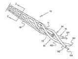
- FIG. 1schematically illustrates a part of an arrangement according to a preferred embodiment of the invention in perspective
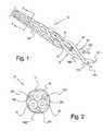
- FIG. 2is a cross sectional view through a cord arrangement of FIG. 1 along line 2 - 2 ,
- FIG. 3is a schematic illustration of a cord, according to the invention, connected to a distributor, and
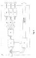
- FIG. 4is an exemplary block diagram of a controlling arrangement.
- FIGS. 1 and 2illustrate an exemplary embodiment of the invention comprising a cord arrangement 10 including three ordinary electrical wires 11 , 12 and 13 arranged around a centre axis.
- the electrical wiresmay extend parallel to the centre axis, as shown in FIG. 1 , but may also be arranged in a twisted configuration around the centre axis.
- the three wiresmay be arranged as power, ground and neutral.
- the inventioncan be realised by twisting a number of illuminating wires 14 , 15 and 16 , which include conductors 141 , 151 and 161 coated by an illuminating coating 142 , 152 and 162 , respectively.
- the illuminating wiresmay be of the type known as electroluminescents, such as described in US 2005037233, WO 031/05538, US 2004067387, WO 03/093394, US 2002/0039666, U.S. Pat. No. 5,485,355 etc.
- the illuminating wiresmay also comprise of wires manufactured under trademark Lytec® by ELAM ltd.
- the illuminating wiresmay also comprise optical fibres, preferably side-emitting optical fibres.
- the twisted electrical wires and illuminating wiresare covered by a light transparent or semi transparent coating 18 , for example made of silicon, rubber etc.
- the present inventionis not limited to three illuminating wires and the invention may be applied using any number of illuminating wires and/or electrical wires.
- FIG. 3illustrates one application of the invention as a cord 30 of a distributor 31 .
- the distributor 31is connected to a wall socket 32 .
- An electric equipment(not shown) is connected to the distributor through a plug 33 .
- the cordis provided with the illuminating wires as mentioned earlier. It is also possible to provide the distributor and the wall plug itself with illuminating wires and consequently using them as part of the indicator.
- the illuminating wiresare connected to a controlling arrangement 34 , in this case arranged inside the distributor.
- Power to the controlling arrangement 40is supplied through a power supply 41 , which is connected to, for example, a wall socket through the cord 30 .
- the poweris adapted to the power level of the electronics in the controlling arrangement.
- the power supplierconverts the power from AC to DC.
- a processing unit 42such as a micro computer is arranged to process the information on power level or current amount received from a measuring arrangement 43 .
- the measuring arrangement 43is arranged between the wall socket and before connection to an electric equipment so that the power and/or current consumption can be measured.
- the measuring arrangementmay sample current and voltage cautiously and provide data to the micro computer.
- the poweris product of current multiplied with voltage. In the event of stable voltage, the phase shift can be ignored and the current can be measured and used to approximate the power. Thus, the difference between the visualisation of current consumption and power consumption can be minimized.
- the micro computercontrols, in this example, three pulse width modulators (PWMs) 44 a - 44 c for controlling analog circuits with a processor's digital outputs.
- the number of PWMscorresponds to the number of illuminating wires.
- the PWMsare connected to drivers 45 a - 45 c, which operate in a suitable range, e.g. 0-110 V, 8 KHz.
- the illuminating wiresare connected to the drivers and thus operate in the output range of the inverter modules.
- the driversmay be inverter modules.
- the driversmay be connected to intensity and/or pulse controlled light sources, such as light emitting diodes (LED) connected to one end of the fibers.
- LEDlight emitting diodes
- the micro computerwill output suitable control signal to the drivers, which feeds the illuminating wires with varying current, voltage and frequency corresponding to the consumed current/voltage through the electrical wires.
- the electroluminescent wiresincludes a central copper wire coated with a phosphorus material coating and two tiny transmitter wires wrapped around it, and covered by a PVC coating and finally a colored vinyl coat.
- the drivertakes the voltage from a DC power source and inverts it to, e.g. 110 volts AC. When connected to a power source and driver, the charge creates a glow in the wire, e.g. very similar to neon.
- the controlling arrangementcontrols the illuminating characteristics, e.g. intensity, color and/or pulsing (frequency) of the illuminating wires in relation to the consumed power and/or current through the electric wires. This allows obtaining a simultaneous characteristic change, shifting the pulsing in the wires to obtain visual effects such as flowing light, etc.
- controlling arrangementand input and output values are given as an example and other types of controlling arrangement operating with different electrical values may occur.
- the inventionis not limited to applications in cables and cords, especially distributor cords; the invention may likewise be applied in household appliance for providing visual indication of poser consumption of different appliances.
- the visualizationmay be used for indicating overload. Especially, if many apparatuses are connected, it is possible to track a particular apparatus being overloaded or consuming high power by following the visually indicating cable.
- the visualizationallows finding cables in limited sight situations.
Landscapes
- Physics & Mathematics (AREA)
- General Physics & Mathematics (AREA)
- Optics & Photonics (AREA)
- Engineering & Computer Science (AREA)
- Power Engineering (AREA)
- Electroluminescent Light Sources (AREA)
- Illuminated Signs And Luminous Advertising (AREA)
- Circuit Arrangement For Electric Light Sources In General (AREA)
- Eye Examination Apparatus (AREA)
Abstract
Description
Claims (17)
Applications Claiming Priority (4)
| Application Number | Priority Date | Filing Date | Title |
|---|---|---|---|
| SE0500523-6 | 2005-03-07 | ||
| SE0500523 | 2005-03-07 | ||
| SE0500523ASE528408C2 (en) | 2005-03-07 | 2005-03-07 | A method and apparatus for visual indication of power or power consumption in an electrical cable |
| PCT/SE2006/000283WO2006096115A1 (en) | 2005-03-07 | 2006-03-06 | Visualisation arrangement |
Publications (2)
| Publication Number | Publication Date |
|---|---|
| US20080191890A1 US20080191890A1 (en) | 2008-08-14 |
| US8791829B2true US8791829B2 (en) | 2014-07-29 |
Family
ID=36953638
Family Applications (1)
| Application Number | Title | Priority Date | Filing Date |
|---|---|---|---|
| US11/885,697Active2031-01-07US8791829B2 (en) | 2005-03-07 | 2006-03-06 | Visualisation arrangement |
Country Status (10)
| Country | Link |
|---|---|
| US (1) | US8791829B2 (en) |
| EP (1) | EP1856543B1 (en) |
| DK (1) | DK1856543T3 (en) |
| ES (1) | ES2860762T3 (en) |
| HU (1) | HUE053753T2 (en) |
| LT (1) | LT1856543T (en) |
| PL (1) | PL1856543T3 (en) |
| PT (1) | PT1856543T (en) |
| SE (1) | SE528408C2 (en) |
| WO (1) | WO2006096115A1 (en) |
Cited By (13)
| Publication number | Priority date | Publication date | Assignee | Title |
|---|---|---|---|---|
| US20160139353A1 (en)* | 2014-11-18 | 2016-05-19 | Corning Optical Communications LLC | Traceable optical fiber cable and filtered viewing device for enhanced traceability |
| US10101553B2 (en) | 2015-05-20 | 2018-10-16 | Corning Optical Communications LLC | Traceable cable with side-emitting optical fiber and method of forming the same |
| US10101545B2 (en) | 2015-10-30 | 2018-10-16 | Corning Optical Communications LLC | Traceable cable assembly and connector |
| US10107983B2 (en) | 2016-04-29 | 2018-10-23 | Corning Optical Communications LLC | Preferential mode coupling for enhanced traceable patch cord performance |
| US10185111B2 (en) | 2016-04-08 | 2019-01-22 | Corning Optical Communications LLC | Traceable end point cable assembly |
| US10222561B2 (en) | 2016-12-21 | 2019-03-05 | Corning Research & Development Corporation | Light launch device for transmitting light into a traceable fiber optic cable assembly with tracing optical fibers |
| US10228526B2 (en) | 2015-03-31 | 2019-03-12 | Corning Optical Communications LLC | Traceable cable with side-emitting optical fiber and method of forming the same |
| US10234614B2 (en) | 2017-01-20 | 2019-03-19 | Corning Research & Development Corporation | Light source assemblies and systems and methods with mode homogenization |
| US10338317B2 (en) | 2015-07-17 | 2019-07-02 | Corning Optical Communications LLC | Systems and methods for traceable cables |
| US10534135B2 (en) | 2015-07-17 | 2020-01-14 | Corning Optical Communications LLC | Systems and methods for tracing cables and cables for such systems and methods |
| US10539747B2 (en) | 2017-12-05 | 2020-01-21 | Corning Research & Development Corporation | Bend induced light scattering fiber and cable assemblies and method of making |
| US10539758B2 (en) | 2017-12-05 | 2020-01-21 | Corning Research & Development Corporation | Traceable fiber optic cable assembly with indication of polarity |
| US11137518B2 (en)* | 2014-12-16 | 2021-10-05 | Koninklijke Philips N.V. | Marine cable device adapted for the prevention of fouling |
Families Citing this family (2)
| Publication number | Priority date | Publication date | Assignee | Title |
|---|---|---|---|---|
| CN114556116A (en)* | 2019-10-15 | 2022-05-27 | 沃尔沃建筑设备公司 | Device for indicating the state of a cable |
| EP4220210A1 (en)* | 2022-01-28 | 2023-08-02 | Volvo Construction Equipment AB | An apparatus for indicating a status of an electrical cable |
Citations (22)
| Publication number | Priority date | Publication date | Assignee | Title |
|---|---|---|---|---|
| US3819973A (en)* | 1972-11-02 | 1974-06-25 | A Hosford | Electroluminescent filament |
| US5122733A (en) | 1986-01-15 | 1992-06-16 | Karel Havel | Variable color digital multimeter |
| US5485355A (en) | 1992-12-10 | 1996-01-16 | Elam-Electroluminescent Industries Ltd. | Electroluminescent light sources |
| US6169491B1 (en) | 1999-09-30 | 2001-01-02 | Hubbell Incorporated | Multiport power monitor |
| US6347172B1 (en) | 2000-06-28 | 2002-02-12 | Alcatel | Cable having side-emitting fiber under transparent or translucent cable jacket |
| US20020039666A1 (en) | 2000-10-03 | 2002-04-04 | Hideichi Nakamura | Electric luminescence fiber |
| US6377054B1 (en) | 1999-07-20 | 2002-04-23 | Ch. Beha Gmbh | Test device for electrical voltages with integrated illumination unit |
| WO2003093394A1 (en) | 2002-05-03 | 2003-11-13 | Elam-T Limited | Electroluminescent devices |
| WO2003105538A1 (en) | 2002-06-06 | 2003-12-18 | Siba Spelcialty Chemicals Holding Inc. | Electroluminescent device |
| US20040067387A1 (en) | 2002-05-07 | 2004-04-08 | Ji-Eun Kim | Organic compounds for electroluminescence and organic electroluminescent devices using the same |
| US6742909B2 (en)* | 2001-03-07 | 2004-06-01 | The United States Of America As Represented By The Secretary Of The Department Of Health And Human Services | Lighted line |
| US6758314B2 (en)* | 2002-10-31 | 2004-07-06 | George Woodruff | Portable light reel system |
| US20050037233A1 (en) | 2000-06-30 | 2005-02-17 | Dobbs Kerwin D. | Electroluminescent iridium compounds with fluorinated phenylpyridine ligands, and devices made with such compounds |
| US20050040954A1 (en)* | 2003-08-19 | 2005-02-24 | Mcnally Terry C. | Pressure sensitive doorbell mat |
| US20050057942A1 (en)* | 2003-09-12 | 2005-03-17 | Chris Mako | Illumination and reflective strips |
| US20050141237A1 (en)* | 2003-12-26 | 2005-06-30 | Toki Corporation | Illuminating apparatus using full-color LEDs |
| US7068893B2 (en)* | 2003-12-03 | 2006-06-27 | Lg Cable Ltd. | Optical fiber composite electrical power cable |
| US20060291136A1 (en)* | 2005-06-24 | 2006-12-28 | Sanyo Tecnica Co., Ltd. | Lighting equipment |
| US7195561B2 (en)* | 2002-09-24 | 2007-03-27 | Intec, Inc. | Video game controller with illuminated cable |
| US7270442B2 (en)* | 2004-09-30 | 2007-09-18 | General Electric Company | System and method for monitoring status of a visual signal device |
| US7324006B2 (en)* | 2003-11-12 | 2008-01-29 | The Wiremold Company | Remote display ammeter for power plug or power strip |
| US7401961B2 (en)* | 2002-05-02 | 2008-07-22 | Fatzer Ag | Luminous wire rope |
Family Cites Families (9)
| Publication number | Priority date | Publication date | Assignee | Title |
|---|---|---|---|---|
| US5781015A (en)* | 1997-04-03 | 1998-07-14 | Duffin; Stewart R. | Extension cord with integral monitoring system |
| US5917288A (en)* | 1997-06-11 | 1999-06-29 | Feldman; Harold | Sound responsive electroluminescent visual display |
| US5900804A (en)* | 1997-07-11 | 1999-05-04 | Yewell; Ronald E. | Indicating power cord system |
| KR200225528Y1 (en)* | 1997-10-21 | 2001-06-01 | 주석화 | Safety power strip |
| US6147484A (en)* | 1998-07-08 | 2000-11-14 | Smith; Richard T. | Device for measuring power using switchable impedance |
| JP2000195682A (en)* | 1998-12-25 | 2000-07-14 | Hiroyuki Kurokawa | Electroluminescence lighting device |
| US6945663B2 (en) | 2002-06-14 | 2005-09-20 | Tseng-Lu Chien | Tubular electro-luminescent light incorporated with device(s) |
| CN2599895Y (en)* | 2003-01-29 | 2004-01-14 | 何文政 | Variable colour electroluminescent wire |
| WO2005052443A1 (en)* | 2003-11-28 | 2005-06-09 | All Innovations Pty Ltd | Illuminated articles and devices |
- 2005
- 2005-03-07SESE0500523Apatent/SE528408C2/ennot_activeIP Right Cessation
- 2006
- 2006-03-06EPEP06716969.8Apatent/EP1856543B1/enactiveActive
- 2006-03-06DKDK06716969.8Tpatent/DK1856543T3/enactive
- 2006-03-06HUHUE06716969Apatent/HUE053753T2/enunknown
- 2006-03-06PTPT67169698Tpatent/PT1856543T/enunknown
- 2006-03-06PLPL06716969Tpatent/PL1856543T3/enunknown
- 2006-03-06USUS11/885,697patent/US8791829B2/enactiveActive
- 2006-03-06ESES06716969Tpatent/ES2860762T3/enactiveActive
- 2006-03-06WOPCT/SE2006/000283patent/WO2006096115A1/enactiveApplication Filing
- 2006-03-06LTLTEP06716969.8Tpatent/LT1856543T/enunknown
Patent Citations (22)
| Publication number | Priority date | Publication date | Assignee | Title |
|---|---|---|---|---|
| US3819973A (en)* | 1972-11-02 | 1974-06-25 | A Hosford | Electroluminescent filament |
| US5122733A (en) | 1986-01-15 | 1992-06-16 | Karel Havel | Variable color digital multimeter |
| US5485355A (en) | 1992-12-10 | 1996-01-16 | Elam-Electroluminescent Industries Ltd. | Electroluminescent light sources |
| US6377054B1 (en) | 1999-07-20 | 2002-04-23 | Ch. Beha Gmbh | Test device for electrical voltages with integrated illumination unit |
| US6169491B1 (en) | 1999-09-30 | 2001-01-02 | Hubbell Incorporated | Multiport power monitor |
| US6347172B1 (en) | 2000-06-28 | 2002-02-12 | Alcatel | Cable having side-emitting fiber under transparent or translucent cable jacket |
| US20050037233A1 (en) | 2000-06-30 | 2005-02-17 | Dobbs Kerwin D. | Electroluminescent iridium compounds with fluorinated phenylpyridine ligands, and devices made with such compounds |
| US20020039666A1 (en) | 2000-10-03 | 2002-04-04 | Hideichi Nakamura | Electric luminescence fiber |
| US6742909B2 (en)* | 2001-03-07 | 2004-06-01 | The United States Of America As Represented By The Secretary Of The Department Of Health And Human Services | Lighted line |
| US7401961B2 (en)* | 2002-05-02 | 2008-07-22 | Fatzer Ag | Luminous wire rope |
| WO2003093394A1 (en) | 2002-05-03 | 2003-11-13 | Elam-T Limited | Electroluminescent devices |
| US20040067387A1 (en) | 2002-05-07 | 2004-04-08 | Ji-Eun Kim | Organic compounds for electroluminescence and organic electroluminescent devices using the same |
| WO2003105538A1 (en) | 2002-06-06 | 2003-12-18 | Siba Spelcialty Chemicals Holding Inc. | Electroluminescent device |
| US7195561B2 (en)* | 2002-09-24 | 2007-03-27 | Intec, Inc. | Video game controller with illuminated cable |
| US6758314B2 (en)* | 2002-10-31 | 2004-07-06 | George Woodruff | Portable light reel system |
| US20050040954A1 (en)* | 2003-08-19 | 2005-02-24 | Mcnally Terry C. | Pressure sensitive doorbell mat |
| US20050057942A1 (en)* | 2003-09-12 | 2005-03-17 | Chris Mako | Illumination and reflective strips |
| US7324006B2 (en)* | 2003-11-12 | 2008-01-29 | The Wiremold Company | Remote display ammeter for power plug or power strip |
| US7068893B2 (en)* | 2003-12-03 | 2006-06-27 | Lg Cable Ltd. | Optical fiber composite electrical power cable |
| US20050141237A1 (en)* | 2003-12-26 | 2005-06-30 | Toki Corporation | Illuminating apparatus using full-color LEDs |
| US7270442B2 (en)* | 2004-09-30 | 2007-09-18 | General Electric Company | System and method for monitoring status of a visual signal device |
| US20060291136A1 (en)* | 2005-06-24 | 2006-12-28 | Sanyo Tecnica Co., Ltd. | Lighting equipment |
Non-Patent Citations (1)
| Title |
|---|
| International Search Report for PCT/SE2006/000283, mailed Jun. 4, 2006. |
Cited By (16)
| Publication number | Priority date | Publication date | Assignee | Title |
|---|---|---|---|---|
| US10379309B2 (en)* | 2014-11-18 | 2019-08-13 | Corning Optical Communications LLC | Traceable optical fiber cable and filtered viewing device for enhanced traceability |
| US20160139353A1 (en)* | 2014-11-18 | 2016-05-19 | Corning Optical Communications LLC | Traceable optical fiber cable and filtered viewing device for enhanced traceability |
| US11137518B2 (en)* | 2014-12-16 | 2021-10-05 | Koninklijke Philips N.V. | Marine cable device adapted for the prevention of fouling |
| US10228526B2 (en) | 2015-03-31 | 2019-03-12 | Corning Optical Communications LLC | Traceable cable with side-emitting optical fiber and method of forming the same |
| US10101553B2 (en) | 2015-05-20 | 2018-10-16 | Corning Optical Communications LLC | Traceable cable with side-emitting optical fiber and method of forming the same |
| US10338317B2 (en) | 2015-07-17 | 2019-07-02 | Corning Optical Communications LLC | Systems and methods for traceable cables |
| US10534135B2 (en) | 2015-07-17 | 2020-01-14 | Corning Optical Communications LLC | Systems and methods for tracing cables and cables for such systems and methods |
| US10101545B2 (en) | 2015-10-30 | 2018-10-16 | Corning Optical Communications LLC | Traceable cable assembly and connector |
| US10185111B2 (en) | 2016-04-08 | 2019-01-22 | Corning Optical Communications LLC | Traceable end point cable assembly |
| US10107983B2 (en) | 2016-04-29 | 2018-10-23 | Corning Optical Communications LLC | Preferential mode coupling for enhanced traceable patch cord performance |
| US10222560B2 (en) | 2016-12-21 | 2019-03-05 | Corning Research & Development Corporation | Traceable fiber optic cable assembly with fiber guide and tracing optical fibers for carrying light received from a light launch device |
| US10222561B2 (en) | 2016-12-21 | 2019-03-05 | Corning Research & Development Corporation | Light launch device for transmitting light into a traceable fiber optic cable assembly with tracing optical fibers |
| US10545298B2 (en) | 2016-12-21 | 2020-01-28 | Corning Research & Development Corporation | Traceable fiber optic cable assembly with illumination structure and tracing optical fibers for carrying light received from a light launch device |
| US10234614B2 (en) | 2017-01-20 | 2019-03-19 | Corning Research & Development Corporation | Light source assemblies and systems and methods with mode homogenization |
| US10539758B2 (en) | 2017-12-05 | 2020-01-21 | Corning Research & Development Corporation | Traceable fiber optic cable assembly with indication of polarity |
| US10539747B2 (en) | 2017-12-05 | 2020-01-21 | Corning Research & Development Corporation | Bend induced light scattering fiber and cable assemblies and method of making |
Also Published As
| Publication number | Publication date |
|---|---|
| PL1856543T3 (en) | 2021-06-28 |
| EP1856543A4 (en) | 2013-01-02 |
| HUE053753T2 (en) | 2021-07-28 |
| EP1856543A1 (en) | 2007-11-21 |
| WO2006096115A1 (en) | 2006-09-14 |
| EP1856543B1 (en) | 2020-12-30 |
| SE0500523L (en) | 2006-09-08 |
| US20080191890A1 (en) | 2008-08-14 |
| DK1856543T3 (en) | 2021-03-29 |
| PT1856543T (en) | 2021-03-01 |
| ES2860762T3 (en) | 2021-10-05 |
| SE528408C2 (en) | 2006-11-07 |
| LT1856543T (en) | 2021-03-25 |
Similar Documents
| Publication | Publication Date | Title |
|---|---|---|
| US8791829B2 (en) | Visualisation arrangement | |
| CN1917731B (en) | Calibrated led light module | |
| US7406231B1 (en) | Electroluminescent patch cable | |
| US8322871B1 (en) | Optical fiber tracing system | |
| US20170259676A1 (en) | Charging cable for an electric or hybrid vehicle and charging system having such a charging cable | |
| CN103327667B (en) | Flexible LED pixel string with two shielding ground lines | |
| US7936279B2 (en) | Apparatus and method of illuminating indicator lights | |
| RU2475905C2 (en) | Identifiable cable | |
| US7217012B2 (en) | Illuminated signage employing light emitting diodes | |
| US6347172B1 (en) | Cable having side-emitting fiber under transparent or translucent cable jacket | |
| US7671279B2 (en) | Current-seen cable | |
| US20090284169A1 (en) | Systems and Methods for Communicating in a Lighting Network | |
| JP6457509B2 (en) | NETWORK CABLE INCLUDING VISUAL MARKING DEVICE AND VISUAL MARKING DEVICE OF END | |
| EP2735211A1 (en) | Light source comprising a led strip | |
| CN103916999B (en) | A kind of electro luminescence line with direction of arrow instruction | |
| US20220113014A1 (en) | Connection Module for a Luminaire | |
| CN108885127B (en) | Automation field device | |
| US20220344879A1 (en) | Single pair ethernet connector | |
| US20070152842A1 (en) | Micro-processor controlled indicator device | |
| CN110809840B (en) | Cable coupler with power indicator light | |
| CN202696941U (en) | Electroluminescent display device for high voltage measurement | |
| CN108431495B (en) | equipment for image display | |
| JP2008034243A (en) | Light emitting cable | |
| CN117941477A (en) | Electrical device with housing | |
| JP3541381B2 (en) | Probe with input identification function |
Legal Events
| Date | Code | Title | Description |
|---|---|---|---|
| AS | Assignment | Owner name:THE INTERACTIVE INSTITUTE II AB, SWEDEN Free format text:ASSIGNMENT OF ASSIGNORS INTEREST;ASSIGNORS:GUSTAFSSON, ANTON;GYLLENSWARD, MAGNUS;OHMAN, CHRISTINA;AND OTHERS;REEL/FRAME:019832/0656;SIGNING DATES FROM 20070815 TO 20070906 Owner name:THE INTERACTIVE INSTITUTE II AB, SWEDEN Free format text:ASSIGNMENT OF ASSIGNORS INTEREST;ASSIGNORS:GUSTAFSSON, ANTON;GYLLENSWARD, MAGNUS;OHMAN, CHRISTINA;AND OTHERS;SIGNING DATES FROM 20070815 TO 20070906;REEL/FRAME:019832/0656 | |
| STCF | Information on status: patent grant | Free format text:PATENTED CASE | |
| AS | Assignment | Owner name:COUNTERFLO AB, SWEDEN Free format text:NUNC PRO TUNC ASSIGNMENT;ASSIGNOR:INTERACTIVE INSTITUTE SWEDISH ICT AB;REEL/FRAME:037514/0425 Effective date:20150213 | |
| MAFP | Maintenance fee payment | Free format text:PAYMENT OF MAINTENANCE FEE, 4TH YR, SMALL ENTITY (ORIGINAL EVENT CODE: M2551) Year of fee payment:4 | |
| MAFP | Maintenance fee payment | Free format text:PAYMENT OF MAINTENANCE FEE, 8TH YR, SMALL ENTITY (ORIGINAL EVENT CODE: M2552); ENTITY STATUS OF PATENT OWNER: SMALL ENTITY Year of fee payment:8 | |
| IPR | Aia trial proceeding filed before the patent and appeal board: inter partes review | Free format text:TRIAL NO: IPR2023-00362 Opponent name:AMAZON.COM, INC., ANDAMAZON.COM SERVICES LLC Effective date:20221222 |