US8791367B2 - Network cabinet fitting system - Google Patents
Network cabinet fitting systemDownload PDFInfo
- Publication number
- US8791367B2 US8791367B2US12/902,861US90286110AUS8791367B2US 8791367 B2US8791367 B2US 8791367B2US 90286110 AUS90286110 AUS 90286110AUS 8791367 B2US8791367 B2US 8791367B2
- Authority
- US
- United States
- Prior art keywords
- fitting
- grommet
- assembly
- partial cover
- fitting system
- Prior art date
- Legal status (The legal status is an assumption and is not a legal conclusion. Google has not performed a legal analysis and makes no representation as to the accuracy of the status listed.)
- Expired - Fee Related, expires
Links
Images


Classifications
- H—ELECTRICITY
- H02—GENERATION; CONVERSION OR DISTRIBUTION OF ELECTRIC POWER
- H02G—INSTALLATION OF ELECTRIC CABLES OR LINES, OR OF COMBINED OPTICAL AND ELECTRIC CABLES OR LINES
- H02G3/00—Installations of electric cables or lines or protective tubing therefor in or on buildings, equivalent structures or vehicles
- H02G3/22—Installations of cables or lines through walls, floors or ceilings, e.g. into buildings
- H—ELECTRICITY
- H04—ELECTRIC COMMUNICATION TECHNIQUE
- H04Q—SELECTING
- H04Q1/00—Details of selecting apparatus or arrangements
- H04Q1/02—Constructional details
- H04Q1/06—Cable ducts or mountings specially adapted for exchange installations
- H—ELECTRICITY
- H04—ELECTRIC COMMUNICATION TECHNIQUE
- H04Q—SELECTING
- H04Q1/00—Details of selecting apparatus or arrangements
- H04Q1/02—Constructional details
- H04Q1/10—Exchange station construction
- H—ELECTRICITY
- H05—ELECTRIC TECHNIQUES NOT OTHERWISE PROVIDED FOR
- H05K—PRINTED CIRCUITS; CASINGS OR CONSTRUCTIONAL DETAILS OF ELECTRIC APPARATUS; MANUFACTURE OF ASSEMBLAGES OF ELECTRICAL COMPONENTS
- H05K7/00—Constructional details common to different types of electric apparatus
- H05K7/14—Mounting supporting structure in casing or on frame or rack
- H05K7/1485—Servers; Data center rooms, e.g. 19-inch computer racks
- H05K7/1488—Cabinets therefor, e.g. chassis or racks or mechanical interfaces between blades and support structures
- H05K7/1491—Cabinets therefor, e.g. chassis or racks or mechanical interfaces between blades and support structures having cable management arrangements
Definitions
- the present inventionrelates to a network cabinet fitting system. More particularly, the present invention relates to a fitting system for openings in a top cap of a network cabinet.
- network cabinetshave knockouts or removable openings of various sizes to allow cables to enter and exit the cabinet.
- air within the cabinetmay escape through the openings and around the cables and adversely affect the cabinet cooling systems.
- a fitting system for sealing an opening in a top cap of a network cabinetincludes a grommet and at least one of a fitting assembly and a cover.
- the grommetis secured to the opening in the top cap of the network cabinet.
- the fitting assembly and the coverare secured to the grommet and may include at least one finger lift.
- a sleeve or a tubemay be secured to the fitting assembly.
- FIG. 1is a top perspective view of a network cabinet fitting system according to a first preferred embodiment of the present invention
- FIG. 2is a top perspective view of the fitting system of FIG. 1 , showing t he covers removed from the grommets;
- FIG. 3is a bottom perspective view of a small grommet for the fitting system of FIG. 1 ;
- FIG. 4is a bottom perspective view of a large grommet for the fitting system of FIG. 1 ;
- FIG. 5is a top perspective view of a small cover for the fitting system of FIG. 1 ;
- FIG. 6is an enlarged view of the small cover of FIG. 5 , showing a latch
- FIG. 7is a top perspective view of a large cover for the fitting system of FIG. 1 ;
- FIG. 8is a top perspective view of a network cabinet fitting system according to a second preferred embodiment of the present invention.
- FIG. 9is a cross-sectional view of a boot fitting assembly for the fitting system of FIG. 8 ;
- FIG. 10is a top perspective view of a first fitting for the boot fitting assembly of FIG. 9 ;
- FIG. 11is a top perspective view of a second fitting for the boot fitting assembly of FIG. 9 ;
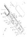
- FIG. 12is a top perspective view of a network cabinet fitting system according to a third preferred embodiment of the present invention.
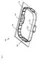
- FIG. 13is a top perspective view of a first fitting for the corrugated tube fitting assembly of FIG. 12 ;
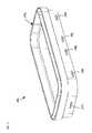
- FIG. 14is a bottom perspective view of a partial cover for the corrugated tube fitting assembly of FIG. 12 ;
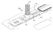
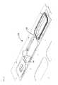
- FIG. 15is a top perspective view of the fitting system of FIG. 12 , showing the first fitting secured to the large grommet;
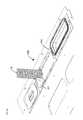
- FIG. 16is a top perspective view of the fitting system of FIG. 12 , showing the corrugated tube positioned in the first fitting;
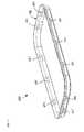
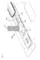
- FIG. 17is a top perspective view of the fitting system of FIG. 12 , showing the second fitting secured to the large grommet;
- FIG. 18is a top perspective view of the fitting system of FIG. 12 , showing the partial cover secured to the large grommet.
- FIGS. 1-7illustrate a network cabinet fitting system 100 according to a first preferred embodiment of the present invention.
- the fitting system 100includes a small grommet 110 , a small cover 120 , a large grommet 130 , and a large cover 140 .
- the small grommet 110is secured to a small opening 11 , such as a 3.5 inch by 5.0 inch opening, in a top cap 10 of a network cabinet (not shown), such as the NET-ACCESSTM network cabinet (Panduit Corp., Tinley Park, Ill.) disclosed in U.S. Pat. No. 7,498,512, the subject matter of which is incorporated by reference in its entirety, and includes radius edges 114 for protecting cables routed therethrough.
- the large grommet 130is secured to a large opening 12 , such as a 3.5 inch by 8.0 inch opening, in the top cap 10 and includes radius edges 134 for protecting cables routed therethrough.
- the small grommet 110includes guides 111 , for inserting the small grommet 110 into the small opening 11 and latches 112 for securing the small grommet 110 to the small opening 11 . Additionally, the small grommet 110 includes stops 113 for locating the corrugated tube fitting assembly 350 ( FIGS. 12-18 ).
- the large grommet 130includes guides 131 , latches 132 , and stops 133 , which are similar to the guides 111 , latches 112 , and stops 113 of the small grommet 110 ( FIG. 3 ).
- the small cover 120includes guides 121 for inserting the small cover 120 into the small grommet 110 and latches 122 for securing the small cover 120 to the small grommet 110 . Additionally, the small cover 120 includes a finger lift 123 for removing the small cover 120 from the small grommet 110 .
- the latches 122include a lead-in angle 124 for inserting the small cover 120 into the small grommet 110 and a ramp angle 125 for removing the small cover 120 from the small grommet 110 without having to manually deflect the latches 122 .
- the large cover 140includes guides 141 , latches 142 , and finger lifts 143 , which are similar to the guides 121 , the latches 122 , and the finger lift 123 of the small cover 120 ( FIGS. 5-6 ).
- FIGS. 8-11illustrate a network cabinet fitting system 200 according to a second preferred embodiment of the present invention.
- the fitting system 200includes the small grommet 110 , the small cover 120 , and the large grommet 130 . Additionally, the fitting system 200 includes a boot fitting assembly 240 . The boot fitting assembly 240 is secured to the large grommet 130 .
- the boot fitting assembly 240includes a first fitting 241 and a second fitting 242 . Together, the fittings 241 , 242 form a channel 243 for receiving a sleeve (not shown), such as the COOL BOOTTM sleeve (Panduit Corp., Tinley Park, Ill.) disclosed in U.S. Pat. No. 7,723,622, the subject matter of which is incorporated by reference in its entirety.
- a sleevesuch as the COOL BOOTTM sleeve (Panduit Corp., Tinley Park, Ill.) disclosed in U.S. Pat. No. 7,723,622, the subject matter of which is incorporated by reference in its entirety.
- the first fitting 241includes latches 244 for securing the first fitting 241 to the large grommet 130 and latches 245 ( FIG. 9 ) for securing the second fitting 242 to the first fitting 241 . Additionally, the first fitting 241 includes a split 246 for installing the first fitting 241 around existing cables.
- the second fitting 242includes openings 247 for securing the second fitting 242 to the first fitting 241 .
- the latches 245 of the first fitting 241are received within the openings 247 of the second fitting 242 .
- the second fitting 242includes a split 248 for installing the second fitting 242 around existing cables.
- FIGS. 12-18illustrate a network cabinet fitting system 300 according to a third preferred embodiment of the present invention.
- the fitting system 300includes the small grommet 110 , the small cover 120 , the large grommet 130 , and the boot fitting assembly 240 .
- the fitting system 300includes a corrugated tube fitting assembly 350 .
- the corrugated tube fitting assembly 350is secured to the large grommet 130 and includes a first fitting 351 , a second fitting 352 , and a partial cover 353 . Together, the fittings 351 , 352 form an opening 354 for receiving a corrugated tube 13 ( FIGS. 16-18 ), for example, from a cable routing system, such as the FIBERRUNNER® cable routing system (Panduit Corp., Tinley Park, Ill.).
- the first fitting 351includes guides 355 , latches 356 , and a finger lift 357 , which are similar to the guides 121 , the latches 122 , and the finger lift 123 of the small cover 120 ( FIGS. 5-6 ).
- the first fitting 351 and the second fitting 352are identical.
- the partial cover 353includes guides 358 , latches 359 , and a finger lift 360 ( FIG. 12 ), which are similar to the guides 121 , the latches 122 , and the finger lift 123 of the small cover 120 ( FIGS. 5-6 ). Additionally, the partial cover 353 includes a lip 361 that overlaps the second fitting 352 and seals the gap between the partial cover 353 and the second fitting 352 .
- FIGS. 15-18illustrate the installation of the corrugated tube fitting assembly 350 .
- the first fitting 351is secured to the large grommet 130 .
- the corrugated tube 13is positioned in the first fitting 351 .
- the corrugated tube 13includes a slit (not shown) for installing the corrugated tube 13 around existing cables.
- the second fitting 352is secured to the large grommet 130 , securing the corrugated tube 13 in the opening 354 ( FIG. 12 ).
- the partial cover 353is secured to the large grommet 130 , sealing the remaining open space 14 ( FIG. 17 ) in the large grommet 130 .
- the corrugated tube fitting assembly 350may be secured to the small grommet 110 , eliminating the need for the partial cover 353 .
- the components of the fitting systems 100 - 300may be combined to form additional embodiments of the present invention.
- the components of the fitting systems 100 - 300such as the small grommet 110 , the small cover 120 , the large grommet 130 , the boot fitting assembly 240 , and the corrugated tube fitting assembly 350 , may be combined to form additional embodiments of the present invention.
- all of the openings 11 , 12 in the top cap 10include a grommet 110 , 130 and at least one of a cover 120 , 140 , a boot fitting assembly 240 , and a corrugated tube fitting assembly 350 .
Landscapes
- Engineering & Computer Science (AREA)
- Computer Networks & Wireless Communication (AREA)
- Architecture (AREA)
- Civil Engineering (AREA)
- Structural Engineering (AREA)
- Computer Hardware Design (AREA)
- General Engineering & Computer Science (AREA)
- Microelectronics & Electronic Packaging (AREA)
- Insulating Bodies (AREA)
- Installation Of Indoor Wiring (AREA)
Abstract
Description
This application claims the benefit of U.S. Provisional Patent Application No. 61/251,429, filed on Oct. 14, 2009, the subject matter of which is incorporated by reference in its entirety.
The present invention relates to a network cabinet fitting system. More particularly, the present invention relates to a fitting system for openings in a top cap of a network cabinet.
Typically, network cabinets have knockouts or removable openings of various sizes to allow cables to enter and exit the cabinet. When cables are run in or out of the cabinet, air within the cabinet may escape through the openings and around the cables and adversely affect the cabinet cooling systems.
Therefore, there is a need for a network cabinet fitting system that seals around cables to reduce air leaks.
A fitting system for sealing an opening in a top cap of a network cabinet. The fitting system includes a grommet and at least one of a fitting assembly and a cover. The grommet is secured to the opening in the top cap of the network cabinet. The fitting assembly and the cover are secured to the grommet and may include at least one finger lift. A sleeve or a tube may be secured to the fitting assembly.
As best seen inFIG. 1 , thefitting system 100 includes asmall grommet 110, asmall cover 120, alarge grommet 130, and alarge cover 140.
As best seen inFIG. 2 , thesmall grommet 110 is secured to asmall opening 11, such as a 3.5 inch by 5.0 inch opening, in atop cap 10 of a network cabinet (not shown), such as the NET-ACCESS™ network cabinet (Panduit Corp., Tinley Park, Ill.) disclosed in U.S. Pat. No. 7,498,512, the subject matter of which is incorporated by reference in its entirety, and includesradius edges 114 for protecting cables routed therethrough. Similarly, thelarge grommet 130 is secured to alarge opening 12, such as a 3.5 inch by 8.0 inch opening, in thetop cap 10 and includesradius edges 134 for protecting cables routed therethrough.
As best seen inFIG. 3 , thesmall grommet 110 includes guides111, for inserting thesmall grommet 110 into thesmall opening 11 andlatches 112 for securing thesmall grommet 110 to thesmall opening 11. Additionally, thesmall grommet 110 includesstops 113 for locating the corrugated tube fitting assembly350 (FIGS. 12-18 ).
As best seen inFIG. 4 , thelarge grommet 130 includesguides 131,latches 132, andstops 133, which are similar to the guides111,latches 112, and stops113 of the small grommet110 (FIG. 3 ).
As best seen inFIG. 5 , thesmall cover 120 includesguides 121 for inserting thesmall cover 120 into thesmall grommet 110 andlatches 122 for securing thesmall cover 120 to thesmall grommet 110. Additionally, thesmall cover 120 includes afinger lift 123 for removing thesmall cover 120 from thesmall grommet 110.
As best seen inFIG. 6 , thelatches 122 include a lead-inangle 124 for inserting thesmall cover 120 into thesmall grommet 110 and aramp angle 125 for removing thesmall cover 120 from thesmall grommet 110 without having to manually deflect thelatches 122.
As best seen inFIG. 7 , thelarge cover 140 includesguides 141,latches 142, andfinger lifts 143, which are similar to theguides 121, thelatches 122, and thefinger lift 123 of the small cover120 (FIGS. 5-6 ).
As best seen inFIG. 9 , theboot fitting assembly 240 includes afirst fitting 241 and asecond fitting 242. Together, thefittings channel 243 for receiving a sleeve (not shown), such as the COOL BOOT™ sleeve (Panduit Corp., Tinley Park, Ill.) disclosed in U.S. Pat. No. 7,723,622, the subject matter of which is incorporated by reference in its entirety.
As best seen inFIG. 10 , thefirst fitting 241 includeslatches 244 for securing thefirst fitting 241 to thelarge grommet 130 and latches245 (FIG. 9 ) for securing thesecond fitting 242 to thefirst fitting 241. Additionally, thefirst fitting 241 includes asplit 246 for installing the first fitting241 around existing cables.
As best seen inFIG. 11 , thesecond fitting 242 includesopenings 247 for securing thesecond fitting 242 to thefirst fitting 241. For example, as shown inFIG. 9 , thelatches 245 of thefirst fitting 241 are received within theopenings 247 of thesecond fitting 242. Additionally, thesecond fitting 242 includes asplit 248 for installing the second fitting242 around existing cables.
As best seen inFIG. 13 , thefirst fitting 351 includesguides 355,latches 356, and afinger lift 357, which are similar to theguides 121, thelatches 122, and thefinger lift 123 of the small cover120 (FIGS. 5-6 ). Preferably, thefirst fitting 351 and thesecond fitting 352 are identical.
As best seen inFIG. 14 , thepartial cover 353 includesguides 358, latches359, and a finger lift360 (FIG. 12 ), which are similar to theguides 121, thelatches 122, and thefinger lift 123 of the small cover120 (FIGS. 5-6 ). Additionally, thepartial cover 353 includes alip 361 that overlaps thesecond fitting 352 and seals the gap between thepartial cover 353 and thesecond fitting 352.
Preferably, the components of the fitting systems100-300, such as thesmall grommet 110, thesmall cover 120, thelarge grommet 130, the bootfitting assembly 240, and the corrugated tubefitting assembly 350, may be combined to form additional embodiments of the present invention.
Preferably, all of theopenings top cap 10 include agrommet cover fitting assembly 240, and a corrugated tubefitting assembly 350.
While the particular preferred embodiments of the present invention have been shown and described, it will be obvious to those skilled in the art that changes and modifications may be made without departing from the teaching of the invention. The matter set forth in the foregoing description and accompanying drawings is offered by way of illustration only and not as limitation. The illustrated embodiments are examples only and should not be taken as limiting the scope of the present invention. The claims should not be read as limited to the described order or elements unless stated to that effect. Therefore, all embodiments that come within the scope and spirit of the following claims and equivalents thereto are claimed as the invention.
Claims (18)
1. A fitting system for sealing a top cap opening in a network cabinet, the fitting system comprising:
a grommet removably connected to the top cap opening;
a fitting assembly removably connected to the grommet, the fitting assembly including a fitting assembly opening and at least one fitting assembly finger lift for removing the fitting assembly from the grommet;
a corrugated tube removably connected to the fitting assembly opening, the corrugated tube defining a cable pathway through the fitting assembly; and
a partial cover removably connected to the grommet adjacent to and independent of the fitting assembly.
2. The fitting system ofclaim 1 , wherein the grommet includes at least one guide for positioning the grommet in the top cap opening.
3. The fitting system ofclaim 1 , wherein the grommet includes at least one latch for securing the grommet to the top cap opening.
4. The fitting system ofclaim 1 , wherein the grommet includes at least one stop for positioning the fitting assembly in the grommet.
5. The fitting system ofclaim 1 , wherein the fitting assembly includes a first fitting removable connected to the grommet and a second fitting removably connected to the grommet.
6. The fitting system ofclaim 5 , wherein the first fitting and the second fitting are identical.
7. The fitting system ofclaim 5 , wherein the first fitting and the second fitting form the fitting assembly opening.
8. The fitting system ofclaim 5 , wherein the first fitting includes at least one first fitting guide for positioning the first fitting in the grommet.
9. The fitting system ofclaim 5 , wherein the first fitting includes at least one first fitting latch for securing the first fitting to the grommet.
10. The fitting system ofclaim 5 , wherein the first fitting includes at least one first fitting finger lift for removing the first fitting from the grommet.
11. The fitting system ofclaim 8 , wherein the second fitting includes at least one second fitting guide for positioning the second fitting in the grommet.
12. The fitting system ofclaim 9 , wherein the second fitting includes at least one second fitting latch for securing the second fitting to the grommet.
13. The fitting system ofclaim 10 , wherein the second fitting includes at least one second fitting finger lift for removing the second fitting from the grommet.
14. The fitting system ofclaim 1 , wherein the partial cover includes a lip that overlaps a portion of the fitting assembly such that the partial cover further secures the fitting assembly to the grommet.
15. The fitting system ofclaim 1 , wherein the partial cover includes at least one guide for positioning the partial cover in the grommet.
16. The fitting system ofclaim 1 , wherein the partial cover includes at least one latch for securing the partial cover to the grommet.
17. The fitting system ofclaim 1 , wherein the partial cover includes at least one partial cover finger lift for removing the partial cover from the grommet.
18. The fitting system ofclaim 17 , wherein the at least one partial cover finger lift is recessed.
Priority Applications (1)
| Application Number | Priority Date | Filing Date | Title |
|---|---|---|---|
| US12/902,861US8791367B2 (en) | 2009-10-14 | 2010-10-12 | Network cabinet fitting system |
Applications Claiming Priority (2)
| Application Number | Priority Date | Filing Date | Title |
|---|---|---|---|
| US25142909P | 2009-10-14 | 2009-10-14 | |
| US12/902,861US8791367B2 (en) | 2009-10-14 | 2010-10-12 | Network cabinet fitting system |
Publications (2)
| Publication Number | Publication Date |
|---|---|
| US20110083873A1 US20110083873A1 (en) | 2011-04-14 |
| US8791367B2true US8791367B2 (en) | 2014-07-29 |
Family
ID=43853922
Family Applications (1)
| Application Number | Title | Priority Date | Filing Date |
|---|---|---|---|
| US12/902,861Expired - Fee RelatedUS8791367B2 (en) | 2009-10-14 | 2010-10-12 | Network cabinet fitting system |
Country Status (1)
| Country | Link |
|---|---|
| US (1) | US8791367B2 (en) |
Cited By (3)
| Publication number | Priority date | Publication date | Assignee | Title |
|---|---|---|---|---|
| US20130130613A1 (en)* | 2010-07-30 | 2013-05-23 | Panasonic Corporation | Fire damper for ventilating fan |
| US20190132986A1 (en)* | 2017-10-31 | 2019-05-02 | King Slide Works Co., Ltd. | Slide rail mechanism |
| US11613171B2 (en)* | 2019-05-08 | 2023-03-28 | Webasto SE | Top comprising a cable guide |
Families Citing this family (12)
| Publication number | Priority date | Publication date | Assignee | Title |
|---|---|---|---|---|
| EP2429272A2 (en) | 2010-09-10 | 2012-03-14 | Chatsworth Products, Inc. | Cable pass-through panel for electronic equipment enclosure |
| US8787023B2 (en) | 2010-09-10 | 2014-07-22 | Chatsworth Products, Inc. | Rail mounting clamp for electronic equipment enclosure |
| US8901438B2 (en) | 2010-09-10 | 2014-12-02 | Chatsworth Products, Inc. | Electronic equipment cabinet structure |
| JP2017520887A (en) | 2014-06-05 | 2017-07-27 | チャッツワース プロダクツ、インク. | Electrical outlet with locking mechanism |
| WO2018022721A1 (en)* | 2016-07-26 | 2018-02-01 | Chatsworth Products, Inc. | Features for cable managers and other electronic equipment structures |
| US10547145B2 (en) | 2018-02-05 | 2020-01-28 | Chatworth Products, Inc. | Electric receptacle with locking feature |
| US11527877B2 (en)* | 2019-11-25 | 2022-12-13 | Te Connectivity Solutions Gmbh | Electrical element pass through plate constructions |
| US11622458B1 (en)* | 2020-12-15 | 2023-04-04 | Chatsworth Products, Inc. | Brush port assembly and method for installing same |
| US12048108B1 (en) | 2020-12-15 | 2024-07-23 | Chatsworth Products, Inc. | Caster attachment system using mating features |
| US11678456B1 (en) | 2020-12-15 | 2023-06-13 | Chatsworth Products, Inc. | Slidable mounting hardware for electronic equipment enclosure and method for installing same |
| US11818860B1 (en) | 2020-12-15 | 2023-11-14 | Chatsworth Products, Inc. | Frame structure for electronic equipment enclosure |
| US11920392B1 (en) | 2021-02-02 | 2024-03-05 | Chatsworth Products, Inc. | Electrical bonding door hinges |
Citations (70)
| Publication number | Priority date | Publication date | Assignee | Title |
|---|---|---|---|---|
| US3951228A (en) | 1975-01-06 | 1976-04-20 | Continental Can Company, Inc. | Noise reduction enclosure for a machine |
| US4403106A (en) | 1981-09-21 | 1983-09-06 | Northern Telecom Limited | Terminal enclosure for cable stubs, with variable entry positions |
| US4432520A (en)* | 1981-02-13 | 1984-02-21 | Hans Simon | Strain relief assembly |
| US4656689A (en)* | 1986-04-01 | 1987-04-14 | Molded Products Company | Grommet |
| US4688491A (en)* | 1986-09-08 | 1987-08-25 | Allsteel Inc. | Grommet arrangement for office furniture desk tops |
| US4717358A (en)* | 1986-07-31 | 1988-01-05 | Amp Incorporated | Cover plates for power distribution system |
| US4730363A (en) | 1986-09-17 | 1988-03-15 | Illinois Tool Works, Inc. | Wiring grommet with retractable lid |
| US4731501A (en) | 1985-06-19 | 1988-03-15 | Northern Telecom Limited | Entrance terminals for telecommunications cable |
| USD298494S (en) | 1985-08-27 | 1988-11-15 | Mockett Douglas A J | Cord access grommet set for office furniture use |
| US4814547A (en) | 1987-10-06 | 1989-03-21 | Cooper Industries, Inc. | Cable connector |
| US4864080A (en) | 1987-06-01 | 1989-09-05 | The Carlon Company | Terminator connector fitting for electrical box and conduit system |
| US4928349A (en) | 1987-07-15 | 1990-05-29 | Yazaki Corporation | Grommet structure |
| US5101079A (en) | 1990-07-11 | 1992-03-31 | Thomas & Betts Corporation | Enclosure for an electrical terminal block including barrier means for a cable entry opening |
| US5113475A (en) | 1990-03-14 | 1992-05-12 | Smiths Industries Public Limited Co. | Fibre-optic entry to an enclosure |
| US5167047A (en) | 1991-10-01 | 1992-12-01 | Plumley Roger K | Wire management grommet |
| US5170008A (en) | 1991-08-29 | 1992-12-08 | International Business Machines Corp. | External cable grommet for cable entry of EMI protected cabinets |
| GB2262397A (en) | 1991-12-03 | 1993-06-16 | Sumitomo Wall Systems Ltd | A grommet |
| US5254808A (en) | 1990-07-11 | 1993-10-19 | Thomas & Betts Corporation | Enclosure for an electrical terminal block including barrier means for a cable entry opening |
| USD355110S (en)* | 1992-08-10 | 1995-02-07 | Hon Industries Inc. | Wire management grommet |
| DE4326242A1 (en) | 1993-08-02 | 1995-02-09 | Siemens Ag | Device for the sealed introduction of a cable into a switching cabinet |
| US5442140A (en)* | 1993-10-05 | 1995-08-15 | Homac Mfg. Company | Conduit and cable sealer |
| US5546495A (en) | 1993-04-16 | 1996-08-13 | The Whitaker Corporation | Splice tray rack and cabinet for fiber optic cables |
| US5589663A (en) | 1992-12-23 | 1996-12-31 | Elkay Electrical Manufacturing Company Limited | Earthed cable gland |
| US5675124A (en) | 1996-04-30 | 1997-10-07 | Stough; Robert Eugene | Grommet for a fiber optic enclosure |
| US5686700A (en) | 1994-11-14 | 1997-11-11 | Carpin Manufacturing, Inc. | Adjustable cable management grommet |
| US5696351A (en) | 1995-03-10 | 1997-12-09 | Ericsson Raynet | Cable retention and sealing device |
| US5732180A (en) | 1995-06-09 | 1998-03-24 | Multilink, Inc. | Method and apparatus for sealing fiber optic entryways to a sealed enclosure |
| US5806140A (en) | 1996-05-23 | 1998-09-15 | The Siemon Company | Rotatable grommet |
| US5860713A (en)* | 1997-06-04 | 1999-01-19 | Anderson Hickey Company | Wire management arrangement |
| US5886300A (en) | 1996-04-30 | 1999-03-23 | The Whitaker Corporation | Plug for a sealing grommet |
| US5908180A (en)* | 1998-03-19 | 1999-06-01 | Lucent Technologies Inc. | Symmetrical cable bracketing and strain relieving mechanism and method |
| US5959250A (en) | 1998-06-25 | 1999-09-28 | Lucent Technologies Inc. | Sealing device for telecommunications equipment enclosures |
| US6015197A (en) | 1998-02-28 | 2000-01-18 | 3Com Corp. | Protective grommet apparatus and method |
| US6044193A (en) | 1998-07-10 | 2000-03-28 | Siecor Operations, Llc | Fiber optic interconnection enclosure having a forced air system |
| US6162989A (en) | 1998-06-22 | 2000-12-19 | Honeywell Inc | Cable entry shield (EMI-RFI) for electronic units |
| US6194659B1 (en) | 1997-05-14 | 2001-02-27 | Legrand | Cable entry device |
| US6248952B1 (en) | 1999-03-15 | 2001-06-19 | Delphi Technologies, Inc. | Wiring protection dress for automotive electrical wiring extending between a splash shield and tubular conduits |
| US6263634B1 (en) | 1999-09-23 | 2001-07-24 | Rotary Press Systems Inc. | Grommet for use with sheet metal structural member |
| DE10027486A1 (en) | 2000-06-02 | 2001-12-13 | Rapp Wildner Heike | Cable bush system penetrating casing walls, comprises snap-in outer sleeve, cone plug and split bush with variable opening |
| US6351592B1 (en) | 1998-06-12 | 2002-02-26 | Netrix Technologies, Inc. | Multi-purpose communications cabinet |
| US6376777B1 (en) | 1999-05-27 | 2002-04-23 | Sumitomo Wiring Systems, Ltd. | Grommet |
| US6383034B1 (en) | 2001-02-23 | 2002-05-07 | Corning Cable Systems Llc | Network access terminal |
| US6393658B1 (en) | 1999-01-29 | 2002-05-28 | The Marvel Group, Inc. | Cable port grommet for modular office furniture |
| US6554697B1 (en)* | 1998-12-30 | 2003-04-29 | Engineering Equipment And Services, Inc. | Computer cabinet design |
| US6686540B2 (en)* | 2000-06-08 | 2004-02-03 | Carlo Compagnone, Jr. | Temporary protective cover for an electrical box |
| US6694566B1 (en) | 1992-06-22 | 2004-02-24 | Douglas A. J. Mockett | Grommet |
| US6776707B2 (en) | 1998-12-30 | 2004-08-17 | Engineering Equipment And Services, Inc. | Computer cabinet |
| US6950593B2 (en) | 2001-05-21 | 2005-09-27 | Wave7 Optics, Inc. | Cable splice enclosure |
| US6995316B1 (en)* | 2004-08-04 | 2006-02-07 | Tyco Electronics Canada, Ltd. | Overmolded wire sealing assembly |
| US7010210B2 (en) | 2002-06-21 | 2006-03-07 | Nortel Networks Limited | Entry and internal fiber clips for a fiber management system |
| US7046521B2 (en) | 2002-03-13 | 2006-05-16 | Garmong Victor H | Enclosure with shielded power compartment and methods of shielding enclosures |
| US7266281B1 (en) | 2005-07-07 | 2007-09-04 | Flatau Joseph G | Optical fiber patch box |
| US7276659B2 (en) | 2005-05-31 | 2007-10-02 | Hoffman Enclosures, Inc. | Enclosure having a closure member |
| US7293666B2 (en) | 2004-11-17 | 2007-11-13 | American Power Conversion Corporation | Equipment enclosure kit and assembly method |
| US20070273256A1 (en) | 2006-05-23 | 2007-11-29 | Martin Kirt D | Grommet cover assembly |
| US20070278005A1 (en) | 2005-04-01 | 2007-12-06 | Adc Telecommunications, Inc. | Split cable seal |
| USD560114S1 (en) | 1992-06-22 | 2008-01-22 | Mockett Douglas A J | Grommet cap |
| US20080118216A1 (en) | 2006-11-22 | 2008-05-22 | Alcatel Lucent | Cable entry seal |
| US7388156B2 (en)* | 2005-12-15 | 2008-06-17 | Teleflex Automotive Germany Gmbh | Gasket for a cable control line in an engine compartment |
| US20080253730A1 (en) | 2007-04-10 | 2008-10-16 | Terry Dean Cox | Grommet and plate assembly for sealing fiber optic closures |
| US7496268B2 (en) | 2006-12-13 | 2009-02-24 | Corning Cable Systems Llc | High density fiber optic hardware |
| US7498512B2 (en)* | 2006-03-13 | 2009-03-03 | Panduit Corp. | Network cabinet |
| US7507912B1 (en) | 2007-10-01 | 2009-03-24 | Upsite Technologies, Inc. | Grommet for cables |
| US7615714B2 (en)* | 2005-07-21 | 2009-11-10 | Thomas & Betts International, Inc. | Button style cord connector |
| WO2009142885A1 (en) | 2008-05-20 | 2009-11-26 | Panduit Corp. | Cable drop system |
| US20090302034A1 (en) | 2006-05-15 | 2009-12-10 | Maekelae Keijo | Enclosure with a Lead-Through and a Grommet |
| US20100148015A1 (en) | 2008-12-08 | 2010-06-17 | Matsuno Hiroto | Clamp for corrugated tube |
| US20110001408A1 (en) | 2009-07-06 | 2011-01-06 | Panduit Corp. | Network Cabinet Fitting System |
| US7871079B2 (en)* | 2007-05-22 | 2011-01-18 | Panduit Corp. | Sealing assembly |
| US8249411B2 (en)* | 2010-04-22 | 2012-08-21 | Channell Commercial Corporation | Portable optical fiber distribution enclosure |
- 2010
- 2010-10-12USUS12/902,861patent/US8791367B2/ennot_activeExpired - Fee Related
Patent Citations (79)
| Publication number | Priority date | Publication date | Assignee | Title |
|---|---|---|---|---|
| US3951228A (en) | 1975-01-06 | 1976-04-20 | Continental Can Company, Inc. | Noise reduction enclosure for a machine |
| US4432520A (en)* | 1981-02-13 | 1984-02-21 | Hans Simon | Strain relief assembly |
| US4403106A (en) | 1981-09-21 | 1983-09-06 | Northern Telecom Limited | Terminal enclosure for cable stubs, with variable entry positions |
| US4731501A (en) | 1985-06-19 | 1988-03-15 | Northern Telecom Limited | Entrance terminals for telecommunications cable |
| USD298494S (en) | 1985-08-27 | 1988-11-15 | Mockett Douglas A J | Cord access grommet set for office furniture use |
| US4656689A (en)* | 1986-04-01 | 1987-04-14 | Molded Products Company | Grommet |
| US4717358A (en)* | 1986-07-31 | 1988-01-05 | Amp Incorporated | Cover plates for power distribution system |
| US4688491A (en)* | 1986-09-08 | 1987-08-25 | Allsteel Inc. | Grommet arrangement for office furniture desk tops |
| US4730363A (en) | 1986-09-17 | 1988-03-15 | Illinois Tool Works, Inc. | Wiring grommet with retractable lid |
| US4864080A (en) | 1987-06-01 | 1989-09-05 | The Carlon Company | Terminator connector fitting for electrical box and conduit system |
| US4928349A (en) | 1987-07-15 | 1990-05-29 | Yazaki Corporation | Grommet structure |
| US4814547A (en) | 1987-10-06 | 1989-03-21 | Cooper Industries, Inc. | Cable connector |
| US5113475A (en) | 1990-03-14 | 1992-05-12 | Smiths Industries Public Limited Co. | Fibre-optic entry to an enclosure |
| US5101079A (en) | 1990-07-11 | 1992-03-31 | Thomas & Betts Corporation | Enclosure for an electrical terminal block including barrier means for a cable entry opening |
| US5254808A (en) | 1990-07-11 | 1993-10-19 | Thomas & Betts Corporation | Enclosure for an electrical terminal block including barrier means for a cable entry opening |
| US5170008A (en) | 1991-08-29 | 1992-12-08 | International Business Machines Corp. | External cable grommet for cable entry of EMI protected cabinets |
| US5167047A (en) | 1991-10-01 | 1992-12-01 | Plumley Roger K | Wire management grommet |
| GB2262397A (en) | 1991-12-03 | 1993-06-16 | Sumitomo Wall Systems Ltd | A grommet |
| US6694566B1 (en) | 1992-06-22 | 2004-02-24 | Douglas A. J. Mockett | Grommet |
| US7788766B2 (en)* | 1992-06-22 | 2010-09-07 | Mockett Douglas A J | Wire management grommet with non-captive closure member |
| US20080178421A1 (en) | 1992-06-22 | 2008-07-31 | Mockett Douglas A J | Wire management grommet with non-captive closure member |
| US7155775B2 (en) | 1992-06-22 | 2007-01-02 | Mockett Douglas A J | Wire management grommet with non-captive closure member |
| US7383610B2 (en) | 1992-06-22 | 2008-06-10 | Mockett Douglas A J | Wire management grommet with non-captive closure member |
| US7124468B2 (en) | 1992-06-22 | 2006-10-24 | Mockett Douglas A J | Wire management grommet with non-captive closure member and sleeve |
| USD560114S1 (en) | 1992-06-22 | 2008-01-22 | Mockett Douglas A J | Grommet cap |
| US6877184B2 (en) | 1992-06-22 | 2005-04-12 | Douglas A. J. Mockett | Grommet |
| USD355110S (en)* | 1992-08-10 | 1995-02-07 | Hon Industries Inc. | Wire management grommet |
| US5589663A (en) | 1992-12-23 | 1996-12-31 | Elkay Electrical Manufacturing Company Limited | Earthed cable gland |
| US5546495A (en) | 1993-04-16 | 1996-08-13 | The Whitaker Corporation | Splice tray rack and cabinet for fiber optic cables |
| DE4326242A1 (en) | 1993-08-02 | 1995-02-09 | Siemens Ag | Device for the sealed introduction of a cable into a switching cabinet |
| US5442140A (en)* | 1993-10-05 | 1995-08-15 | Homac Mfg. Company | Conduit and cable sealer |
| US5686700A (en) | 1994-11-14 | 1997-11-11 | Carpin Manufacturing, Inc. | Adjustable cable management grommet |
| US5696351A (en) | 1995-03-10 | 1997-12-09 | Ericsson Raynet | Cable retention and sealing device |
| US5732180A (en) | 1995-06-09 | 1998-03-24 | Multilink, Inc. | Method and apparatus for sealing fiber optic entryways to a sealed enclosure |
| US5886300A (en) | 1996-04-30 | 1999-03-23 | The Whitaker Corporation | Plug for a sealing grommet |
| US5675124A (en) | 1996-04-30 | 1997-10-07 | Stough; Robert Eugene | Grommet for a fiber optic enclosure |
| US5806140A (en) | 1996-05-23 | 1998-09-15 | The Siemon Company | Rotatable grommet |
| US6194659B1 (en) | 1997-05-14 | 2001-02-27 | Legrand | Cable entry device |
| US5860713A (en)* | 1997-06-04 | 1999-01-19 | Anderson Hickey Company | Wire management arrangement |
| US6015197A (en) | 1998-02-28 | 2000-01-18 | 3Com Corp. | Protective grommet apparatus and method |
| US5908180A (en)* | 1998-03-19 | 1999-06-01 | Lucent Technologies Inc. | Symmetrical cable bracketing and strain relieving mechanism and method |
| US6351592B1 (en) | 1998-06-12 | 2002-02-26 | Netrix Technologies, Inc. | Multi-purpose communications cabinet |
| US6162989A (en) | 1998-06-22 | 2000-12-19 | Honeywell Inc | Cable entry shield (EMI-RFI) for electronic units |
| US5959250A (en) | 1998-06-25 | 1999-09-28 | Lucent Technologies Inc. | Sealing device for telecommunications equipment enclosures |
| US6044193A (en) | 1998-07-10 | 2000-03-28 | Siecor Operations, Llc | Fiber optic interconnection enclosure having a forced air system |
| US6554697B1 (en)* | 1998-12-30 | 2003-04-29 | Engineering Equipment And Services, Inc. | Computer cabinet design |
| US6776707B2 (en) | 1998-12-30 | 2004-08-17 | Engineering Equipment And Services, Inc. | Computer cabinet |
| US6393658B1 (en) | 1999-01-29 | 2002-05-28 | The Marvel Group, Inc. | Cable port grommet for modular office furniture |
| US6248952B1 (en) | 1999-03-15 | 2001-06-19 | Delphi Technologies, Inc. | Wiring protection dress for automotive electrical wiring extending between a splash shield and tubular conduits |
| US6376777B1 (en) | 1999-05-27 | 2002-04-23 | Sumitomo Wiring Systems, Ltd. | Grommet |
| US6263634B1 (en) | 1999-09-23 | 2001-07-24 | Rotary Press Systems Inc. | Grommet for use with sheet metal structural member |
| DE10027486A1 (en) | 2000-06-02 | 2001-12-13 | Rapp Wildner Heike | Cable bush system penetrating casing walls, comprises snap-in outer sleeve, cone plug and split bush with variable opening |
| US6686540B2 (en)* | 2000-06-08 | 2004-02-03 | Carlo Compagnone, Jr. | Temporary protective cover for an electrical box |
| US6383034B1 (en) | 2001-02-23 | 2002-05-07 | Corning Cable Systems Llc | Network access terminal |
| US6950593B2 (en) | 2001-05-21 | 2005-09-27 | Wave7 Optics, Inc. | Cable splice enclosure |
| US7046521B2 (en) | 2002-03-13 | 2006-05-16 | Garmong Victor H | Enclosure with shielded power compartment and methods of shielding enclosures |
| US7010210B2 (en) | 2002-06-21 | 2006-03-07 | Nortel Networks Limited | Entry and internal fiber clips for a fiber management system |
| US6995316B1 (en)* | 2004-08-04 | 2006-02-07 | Tyco Electronics Canada, Ltd. | Overmolded wire sealing assembly |
| US7293666B2 (en) | 2004-11-17 | 2007-11-13 | American Power Conversion Corporation | Equipment enclosure kit and assembly method |
| US20070278005A1 (en) | 2005-04-01 | 2007-12-06 | Adc Telecommunications, Inc. | Split cable seal |
| US7276659B2 (en) | 2005-05-31 | 2007-10-02 | Hoffman Enclosures, Inc. | Enclosure having a closure member |
| US7266281B1 (en) | 2005-07-07 | 2007-09-04 | Flatau Joseph G | Optical fiber patch box |
| US7615714B2 (en)* | 2005-07-21 | 2009-11-10 | Thomas & Betts International, Inc. | Button style cord connector |
| US7388156B2 (en)* | 2005-12-15 | 2008-06-17 | Teleflex Automotive Germany Gmbh | Gasket for a cable control line in an engine compartment |
| US7498512B2 (en)* | 2006-03-13 | 2009-03-03 | Panduit Corp. | Network cabinet |
| US20090302034A1 (en) | 2006-05-15 | 2009-12-10 | Maekelae Keijo | Enclosure with a Lead-Through and a Grommet |
| US20070273256A1 (en) | 2006-05-23 | 2007-11-29 | Martin Kirt D | Grommet cover assembly |
| US20080118216A1 (en) | 2006-11-22 | 2008-05-22 | Alcatel Lucent | Cable entry seal |
| US7751676B2 (en) | 2006-11-22 | 2010-07-06 | Alcatel Lucent | Cable entry seal |
| US7496268B2 (en) | 2006-12-13 | 2009-02-24 | Corning Cable Systems Llc | High density fiber optic hardware |
| US7668431B2 (en) | 2007-04-10 | 2010-02-23 | Corning Cable Systems Llc | Grommet and plate assembly for sealing fiber optic closures |
| US20080253730A1 (en) | 2007-04-10 | 2008-10-16 | Terry Dean Cox | Grommet and plate assembly for sealing fiber optic closures |
| US7871079B2 (en)* | 2007-05-22 | 2011-01-18 | Panduit Corp. | Sealing assembly |
| US20090151983A1 (en) | 2007-10-01 | 2009-06-18 | Sempliner Arthur T | Grommet for cables |
| US7507912B1 (en) | 2007-10-01 | 2009-03-24 | Upsite Technologies, Inc. | Grommet for cables |
| WO2009142885A1 (en) | 2008-05-20 | 2009-11-26 | Panduit Corp. | Cable drop system |
| US20100148015A1 (en) | 2008-12-08 | 2010-06-17 | Matsuno Hiroto | Clamp for corrugated tube |
| US20110001408A1 (en) | 2009-07-06 | 2011-01-06 | Panduit Corp. | Network Cabinet Fitting System |
| US8249411B2 (en)* | 2010-04-22 | 2012-08-21 | Channell Commercial Corporation | Portable optical fiber distribution enclosure |
Cited By (6)
| Publication number | Priority date | Publication date | Assignee | Title |
|---|---|---|---|---|
| US20130130613A1 (en)* | 2010-07-30 | 2013-05-23 | Panasonic Corporation | Fire damper for ventilating fan |
| US9533179B2 (en)* | 2010-07-30 | 2017-01-03 | Panasonic Ecology Systems Guangdong Co., Ltd. | Fire damper for ventilating fan |
| US9868003B2 (en) | 2010-07-30 | 2018-01-16 | Panasonic Ecology Systems Guangdong Co., Ltd. | Fire damper for ventilating fan |
| US20190132986A1 (en)* | 2017-10-31 | 2019-05-02 | King Slide Works Co., Ltd. | Slide rail mechanism |
| US10888014B2 (en)* | 2017-10-31 | 2021-01-05 | King Slide Works Co., Ltd. | Slide rail mechanism |
| US11613171B2 (en)* | 2019-05-08 | 2023-03-28 | Webasto SE | Top comprising a cable guide |
Also Published As
| Publication number | Publication date |
|---|---|
| US20110083873A1 (en) | 2011-04-14 |
Similar Documents
| Publication | Publication Date | Title |
|---|---|---|
| US8791367B2 (en) | Network cabinet fitting system | |
| US20110001408A1 (en) | Network Cabinet Fitting System | |
| US9520703B2 (en) | Electrical busway splice connector | |
| US7829797B2 (en) | Three channel raceway | |
| US6664467B1 (en) | Raceway non-metallic overlapping faceplate mounting bracket | |
| US8848367B2 (en) | Thermal management system | |
| DE502004001730D1 (en) | CABLE MANAGEMENT DEVICE | |
| US7390977B2 (en) | Hanging box and faceplate adapter | |
| CN102844950A (en) | Cable sealing device | |
| US10268010B2 (en) | Clamping and attachment device for cable element | |
| JP5748432B2 (en) | Cover for cable fitting base | |
| US9957978B2 (en) | Ventilation system and ventilation fan housing thereof | |
| JP2009071257A (en) | Box for multimedia port and multimedia port | |
| US20100237757A1 (en) | Distribution Hubs | |
| US9291786B2 (en) | Grommet for fiber optic enclosures | |
| US20250239846A1 (en) | Cable glands | |
| US9485890B2 (en) | Electrical connector system | |
| US7671277B2 (en) | Fitting divider wall for a multi-channel metal raceway | |
| AU2014401308A1 (en) | Cable channel adapter and cable distribution system | |
| US20120024876A1 (en) | Sealed enclosure and system | |
| US20110056722A1 (en) | Wiring Duct Cover With Foam Insert | |
| CA2830401C (en) | Junction box and combined junction box and cable tray assembly | |
| KR101598541B1 (en) | Wall apparatus for pipe line | |
| JP6364632B2 (en) | Ventilator for electrical equipment storage box | |
| CN204349275U (en) | With the distribution box of at least two chambers |
Legal Events
| Date | Code | Title | Description |
|---|---|---|---|
| AS | Assignment | Owner name:PANDUIT CORP., ILLINOIS Free format text:ASSIGNMENT OF ASSIGNORS INTEREST;ASSIGNORS:HARTMAN, SCOTT R.;BLOCK, DALE A.;BLOMQUIST, EDWARD G.;AND OTHERS;SIGNING DATES FROM 20101019 TO 20101027;REEL/FRAME:025208/0316 | |
| STCF | Information on status: patent grant | Free format text:PATENTED CASE | |
| MAFP | Maintenance fee payment | Free format text:PAYMENT OF MAINTENANCE FEE, 4TH YEAR, LARGE ENTITY (ORIGINAL EVENT CODE: M1551) Year of fee payment:4 | |
| FEPP | Fee payment procedure | Free format text:MAINTENANCE FEE REMINDER MAILED (ORIGINAL EVENT CODE: REM.); ENTITY STATUS OF PATENT OWNER: LARGE ENTITY | |
| LAPS | Lapse for failure to pay maintenance fees | Free format text:PATENT EXPIRED FOR FAILURE TO PAY MAINTENANCE FEES (ORIGINAL EVENT CODE: EXP.); ENTITY STATUS OF PATENT OWNER: LARGE ENTITY | |
| STCH | Information on status: patent discontinuation | Free format text:PATENT EXPIRED DUE TO NONPAYMENT OF MAINTENANCE FEES UNDER 37 CFR 1.362 | |
| FP | Lapsed due to failure to pay maintenance fee | Effective date:20220729 |