US8790369B2 - Apparatus and method for repairing tissue - Google Patents
Apparatus and method for repairing tissueDownload PDFInfo
- Publication number
- US8790369B2 US8790369B2US12/609,448US60944809AUS8790369B2US 8790369 B2US8790369 B2US 8790369B2US 60944809 AUS60944809 AUS 60944809AUS 8790369 B2US8790369 B2US 8790369B2
- Authority
- US
- United States
- Prior art keywords
- fixation member
- suture
- fixation
- knot
- opening
- Prior art date
- Legal status (The legal status is an assumption and is not a legal conclusion. Google has not performed a legal analysis and makes no representation as to the accuracy of the status listed.)
- Active, expires
Links
- 238000000034methodMethods0.000titleabstractdescription27
- 230000007547defectEffects0.000claimsabstractdescription38
- -1polyethylenePolymers0.000claimsdescription7
- 239000004698PolyethyleneSubstances0.000claimsdescription6
- 229920000573polyethylenePolymers0.000claimsdescription6
- 229920000642polymerPolymers0.000claimsdescription5
- 230000008878couplingEffects0.000claimsdescription4
- 238000010168coupling processMethods0.000claimsdescription4
- 238000005859coupling reactionMethods0.000claimsdescription4
- 229920002463poly(p-dioxanone) polymerPolymers0.000claimsdescription4
- 239000000622polydioxanoneSubstances0.000claimsdescription4
- 230000008439repair processEffects0.000abstractdescription28
- 238000000429assemblyMethods0.000abstractdescription17
- 230000000712assemblyEffects0.000abstractdescription17
- 210000001519tissueAnatomy0.000description131
- 210000003414extremityAnatomy0.000description76
- 230000017423tissue regenerationEffects0.000description54
- 230000005499meniscusEffects0.000description14
- 210000000988bone and boneAnatomy0.000description9
- 238000004873anchoringMethods0.000description8
- 230000000717retained effectEffects0.000description8
- 230000006378damageEffects0.000description7
- 208000014674injuryDiseases0.000description6
- 210000004872soft tissueAnatomy0.000description6
- 238000001356surgical procedureMethods0.000description6
- 210000003127kneeAnatomy0.000description5
- 239000000463materialSubstances0.000description5
- 208000027418Wounds and injuryDiseases0.000description4
- 230000006835compressionEffects0.000description4
- 238000007906compressionMethods0.000description4
- 238000010276constructionMethods0.000description4
- 230000035876healingEffects0.000description4
- 238000000926separation methodMethods0.000description4
- 210000000689upper legAnatomy0.000description4
- 239000004696Poly ether ether ketoneSubstances0.000description3
- 238000003780insertionMethods0.000description3
- 230000037431insertionEffects0.000description3
- 229920002530polyetherether ketonePolymers0.000description3
- 238000004904shorteningMethods0.000description3
- 208000024288Rotator Cuff injuryDiseases0.000description2
- 230000008901benefitEffects0.000description2
- 230000000149penetrating effectEffects0.000description2
- 230000002093peripheral effectEffects0.000description2
- 229920000139polyethylene terephthalatePolymers0.000description2
- 239000005020polyethylene terephthalateSubstances0.000description2
- 239000000126substanceSubstances0.000description2
- 210000002435tendonAnatomy0.000description2
- 230000008733traumaEffects0.000description2
- 229920010741Ultra High Molecular Weight Polyethylene (UHMWPE)Polymers0.000description1
- 239000004699Ultra-high molecular weight polyethyleneSubstances0.000description1
- 239000000560biocompatible materialSubstances0.000description1
- 239000002775capsuleSubstances0.000description1
- 210000000845cartilageAnatomy0.000description1
- 230000003247decreasing effectEffects0.000description1
- 230000001419dependent effectEffects0.000description1
- 238000005553drillingMethods0.000description1
- 238000010304firingMethods0.000description1
- 210000002758humerusAnatomy0.000description1
- 238000002513implantationMethods0.000description1
- 210000005067joint tissueAnatomy0.000description1
- 210000000629knee jointAnatomy0.000description1
- 210000003041ligamentAnatomy0.000description1
- 238000007726management methodMethods0.000description1
- 238000002324minimally invasive surgeryMethods0.000description1
- 239000000203mixtureSubstances0.000description1
- 229920000728polyesterPolymers0.000description1
- 229920001296polysiloxanePolymers0.000description1
- 230000008569processEffects0.000description1
- 230000004044responseEffects0.000description1
- 210000000513rotator cuffAnatomy0.000description1
- 229920002994synthetic fiberPolymers0.000description1
- 210000002303tibiaAnatomy0.000description1
- 230000000451tissue damageEffects0.000description1
- 231100000827tissue damageToxicity0.000description1
- 230000007704transitionEffects0.000description1
- 229920000785ultra high molecular weight polyethylenePolymers0.000description1
Images


Classifications
- A—HUMAN NECESSITIES
- A61—MEDICAL OR VETERINARY SCIENCE; HYGIENE
- A61B—DIAGNOSIS; SURGERY; IDENTIFICATION
- A61B17/00—Surgical instruments, devices or methods
- A61B17/04—Surgical instruments, devices or methods for suturing wounds; Holders or packages for needles or suture materials
- A61B17/0401—Suture anchors, buttons or pledgets, i.e. means for attaching sutures to bone, cartilage or soft tissue; Instruments for applying or removing suture anchors
- A—HUMAN NECESSITIES
- A61—MEDICAL OR VETERINARY SCIENCE; HYGIENE
- A61B—DIAGNOSIS; SURGERY; IDENTIFICATION
- A61B17/00—Surgical instruments, devices or methods
- A61B17/04—Surgical instruments, devices or methods for suturing wounds; Holders or packages for needles or suture materials
- A61B17/0469—Suturing instruments for use in minimally invasive surgery, e.g. endoscopic surgery
- A—HUMAN NECESSITIES
- A61—MEDICAL OR VETERINARY SCIENCE; HYGIENE
- A61B—DIAGNOSIS; SURGERY; IDENTIFICATION
- A61B17/00—Surgical instruments, devices or methods
- A61B2017/00004—(bio)absorbable, (bio)resorbable or resorptive
- A—HUMAN NECESSITIES
- A61—MEDICAL OR VETERINARY SCIENCE; HYGIENE
- A61B—DIAGNOSIS; SURGERY; IDENTIFICATION
- A61B17/00—Surgical instruments, devices or methods
- A61B17/04—Surgical instruments, devices or methods for suturing wounds; Holders or packages for needles or suture materials
- A61B17/0401—Suture anchors, buttons or pledgets, i.e. means for attaching sutures to bone, cartilage or soft tissue; Instruments for applying or removing suture anchors
- A61B2017/0409—Instruments for applying suture anchors
- A—HUMAN NECESSITIES
- A61—MEDICAL OR VETERINARY SCIENCE; HYGIENE
- A61B—DIAGNOSIS; SURGERY; IDENTIFICATION
- A61B17/00—Surgical instruments, devices or methods
- A61B17/04—Surgical instruments, devices or methods for suturing wounds; Holders or packages for needles or suture materials
- A61B17/0401—Suture anchors, buttons or pledgets, i.e. means for attaching sutures to bone, cartilage or soft tissue; Instruments for applying or removing suture anchors
- A61B2017/0417—T-fasteners
- A—HUMAN NECESSITIES
- A61—MEDICAL OR VETERINARY SCIENCE; HYGIENE
- A61B—DIAGNOSIS; SURGERY; IDENTIFICATION
- A61B17/00—Surgical instruments, devices or methods
- A61B17/04—Surgical instruments, devices or methods for suturing wounds; Holders or packages for needles or suture materials
- A61B17/0401—Suture anchors, buttons or pledgets, i.e. means for attaching sutures to bone, cartilage or soft tissue; Instruments for applying or removing suture anchors
- A61B2017/0446—Means for attaching and blocking the suture in the suture anchor
- A61B2017/0459—Multiple holes in the anchor through which the suture extends and locking the suture when tension is applied
- A—HUMAN NECESSITIES
- A61—MEDICAL OR VETERINARY SCIENCE; HYGIENE
- A61B—DIAGNOSIS; SURGERY; IDENTIFICATION
- A61B17/00—Surgical instruments, devices or methods
- A61B17/04—Surgical instruments, devices or methods for suturing wounds; Holders or packages for needles or suture materials
- A61B17/0401—Suture anchors, buttons or pledgets, i.e. means for attaching sutures to bone, cartilage or soft tissue; Instruments for applying or removing suture anchors
- A61B2017/0464—Suture anchors, buttons or pledgets, i.e. means for attaching sutures to bone, cartilage or soft tissue; Instruments for applying or removing suture anchors for soft tissue
- A—HUMAN NECESSITIES
- A61—MEDICAL OR VETERINARY SCIENCE; HYGIENE
- A61B—DIAGNOSIS; SURGERY; IDENTIFICATION
- A61B17/00—Surgical instruments, devices or methods
- A61B17/04—Surgical instruments, devices or methods for suturing wounds; Holders or packages for needles or suture materials
- A61B17/0469—Suturing instruments for use in minimally invasive surgery, e.g. endoscopic surgery
- A61B2017/0475—Suturing instruments for use in minimally invasive surgery, e.g. endoscopic surgery using sutures having a slip knot
- A—HUMAN NECESSITIES
- A61—MEDICAL OR VETERINARY SCIENCE; HYGIENE
- A61B—DIAGNOSIS; SURGERY; IDENTIFICATION
- A61B17/00—Surgical instruments, devices or methods
- A61B17/04—Surgical instruments, devices or methods for suturing wounds; Holders or packages for needles or suture materials
- A61B17/06—Needles ; Sutures; Needle-suture combinations; Holders or packages for needles or suture materials
- A61B2017/06052—Needle-suture combinations in which a suture is extending inside a hollow tubular needle, e.g. over the entire length of the needle
Definitions
- the inventionrelates generally to devices and methods for repairing tissue. More specifically, the invention relates to suture anchoring devices and methods for arthroscopic repair of tissue defects.
- a variety of injuries and conditionsrequire repair of soft tissue damage, or reattachment of soft tissue to bone and/or surrounding tissue.
- tissue damageor reattachment of soft tissue to bone and/or surrounding tissue.
- surgeryis often required to reattach the tissue to the bone, to allow healing and a natural reattachment to occur.
- suture anchorsor, generically, “suture fixation members,” which typically include an anchor body having one or more suture attachment feature, and a tissue or bone engaging feature for retaining the suture anchor within or adjacent to the tissue or bone.
- suture fixation memberstypically include an anchor body having one or more suture attachment feature, and a tissue or bone engaging feature for retaining the suture anchor within or adjacent to the tissue or bone.
- suture anchorstypically include an anchor body having one or more suture attachment feature, and a tissue or bone engaging feature for retaining the suture anchor within or adjacent to the tissue or bone.
- suture fixation memberstypically include an anchor body having one or more suture attachment feature, and a tissue or bone engaging feature for retaining the suture anchor within or adjacent to the tissue or bone.
- one or more suture anchor connected to, or interconnected by, one or more segment of suturemay used to perform the repair.
- Surgerycan also be required when a tear occurs in the substance of a single type of tissue, for example in the meniscus of the knee (a meniscal tear).
- a tearoccurs in the substance of a single type of tissue, for example in the meniscus of the knee (a meniscal tear).
- One method of repairing such a tearis to stitch it closed by passing a length of suture through the tissue and tying the suture.
- Suturecan also be used in conjunction with one or more suture anchor to repair such tissue tears.
- Suturescan be fastened to suture anchors and to tissue using knots tied by the surgeon during a repair procedure, or using “knotless” devices and methods, where one or more anchor and one or more suture can be connected and tensioned without the surgeon needing to tie knots during the surgery.
- Knotless anchoringis of particular utility for minimally invasive surgeries such as endoscopic or arthroscopic repairs, where the surgeon must remotely manipulate the suture at the surgical site using tools inserted through a small diameter cannula or endoscopic tube, which can make the knotting process difficult and tedious.
- knotless anchoringincluding anchors that automatically lock a suture in position as the anchor is deployed in tissue, anchor components that can controllably lock a suture to the anchor after the anchor is deployed, devices that enable a suture to slide through them in one direction only, and preformed knots that can be tightened by the surgeon using a simple tool, or by tensioning one or more suture strand extending from the knot.
- suture anchoring systemsWhile many suture anchoring systems have been developed for repairing torn tissue, current devices are not without their drawbacks. Some knots or other anchor components may “stand proud” above the repaired tissue's surface especially that surface facing weight bearing contact with bone such as the interface between the femur and the meniscus and interfere with movement and healing of, for example, articulating joint tissue, or the knot's position relative to the anchor or nearby tissue may not be fully under the surgeon's control, in some situations providing a less than optimal repair. In surgeries where two or more suture anchors are joined by suture to repair an injury, any knots or joined suture segments positioned along the suture connecting the anchors to one another can become stress points that limit the ultimate strength of the surgical repair or contribute to surgical trauma.
- An apparatuscomprises first and second fixation members, with each of the first and the second fixation members having a first surface, an opposing second surface, first and second through openings defined between the first surface and the second surface.
- a flexible elementcouples the first and the second fixation members, the flexible element having a first end, a second end and a length therebetween which extends from the first end, in order, along a first end section of suture, through the first opening in the first fixation member from the respective first surface to the respective second surface, through the first opening in the second fixation member from the respective second surface to the respective first surface, through the second opening in the second fixation member from the respective first surface to the respective second surface, through the second opening in the first fixation member from the respective second surface to the respective first surface, and along a second end section of suture.
- the first fixation memberhas a third through opening defined between the respective first and second surface.
- a sliding, locking knotis formed between the first end section and the second end section, with the first end section positioned slidably through the knot and extending from the knot and through the third opening from the first surface to the second surface.
- the first, second and third openings through the first fixation memberare arranged in substantially a straight line along the respective first and second surface.
- the first and the second fixation memberscomprise rounded surfaces between adjacent openings on each respective surface, for sliding the flexible element therealong.
- each of the openingshas a substantially circular cross section.
- one or more of the openingshas an elongated cross section.
- tension applied to the second end section with respect to the first fixation memberis effective to decrease a distance between the first and the second fixation member along the flexible member coupling the first and the second fixation member.
- the first and the second fixation membersfurther comprises a substantially linear groove in each of the respective first and second surfaces, the groove extending from a first end of the respective surface to an opposite end of the respective surface, the groove in the second surface being substantially parallel to the groove in the first surface.
- a delivery devicehas an elongated delivery member within which at least a portion of each of the first and the second fixation members, coupled by the flexible element, is longitudinally and slidably received, preferably with their grooves slidably engaged with a slot in the delivery member.
- the flexible elementcomprises a suture.
- the flexible elementcomprises polyethylene.
- the flexible elementcomprises polyethylene and a bioabsorbable polymer, preferably the bioabsorbable polymer comprises polydioxanone.
- the sliding, locking knotis a bunt line knot.
- a delivery devicewhich comprises a cannula having a proximal end and a distal end, and a longitudinal slot in a wall of the cannula which extends from the distal end toward the proximal end, the cannula is defined by opposing longitudinal edges along the slot.
- the first and the second fixation deviceare received in the cannula along the slot, with the slot edges slidingly engaged in respective grooves in each of the first and the second fixation device.
- a deployment rodis positioned in the cannula, a handle mechanically couples to the proximal end of the cannula, and a manually actuable member is associated with the handle to translate the deployment rod distally in the cannula for expelling one of the first and the second fixation device slidingly from the distal end of the cannula.
- An apparatuscomprises first and second fixation members.
- Each of the first and the second fixation membershaving a first surface and an opposing second surface, first, second and third through openings defined between the first surface and the second surface of the first fixation device, and one or more through openings defined between the first surface and the second surface of the second fixation device.
- a flexible elementcouples the first and the second fixation members.
- Ithas a first end, a second end and a length therebetween, the length extending from the first end, in order, along a first end section of suture, through the first opening in the first fixation member from the respective first surface to the respective second surface, through at least one of the one or more opening in the second fixation member from the respective second surface to the respective first surface, through the second opening in the first fixation member from the respective second surface to the respective first surface, and along a second end section of suture.
- a sliding, locking knotis formed between the first end section and the second end section, the second end section extending from the knot and through the third opening from the first surface to the second surface.
- An apparatuscomprises first and second fixation members coupled by two continuous sections of suture extending therebetween.
- the first fixation memberhas a first surface and an opposing second surface.
- the two suture sectionsare continuous with one another and slidable through an opening through the second fixation member.
- Each of the two sections of sutureextend through respective first and second through openings in the first fixation member from the second surface to the first surface.
- a sliding, locking knotjoins the two continuous sections of suture adjacent to the first surface.
- a third through openingextends between the first surface and the second surface and one of the two continuous sections of suture extends from the knot and through the third opening from the first surface to the second surface.
- An apparatusprovides for repairing a defect in a body tissue. It comprises a first fixation member having a first surface and an opposing second surface, and first, second and third through openings between the first and the second surface.
- a second fixation memberhas one or more through openings.
- the first and the second fixation membersare coupled by a continuous length of suture defining a loop joined by a sliding, locking knot positioned substantially adjacent to the first side of the first fixation member.
- the loopextends from the knot slidably through, in order, the first opening in the first fixation member, at least one of the one or more openings in the second fixation member, the second opening of the first fixation member, and returns to the knot.
- An end section of the continuous length of sutureextends from the knot and through the third opening of the first fixation member from the first side to the second side. Tensioning the end section with respect to the first fixation member is effective to shorten the loop.
- the knotis a bunt line knot, and also preferably the second surface is adapted to contact the tissue being repaired, and the knot is maintained adjacent to the first surface.
- a methodprovides for repairing a defect in a body tissue.
- the methodcomprises the steps of: passing a first fixation member along a first delivery path through the tissue to a first location on a first surface area of the tissue, the first fixation member having opposing first and second surfaces, a sliding and locking suture knot adjacent to the first surface, the suture knot comprising suture, three limbs of suture extending from the second surface along the delivery path, the three limbs of suture each continuous with the suture comprising the knot, a first two of the three limbs together comprising a continuous loop of suture slidingly connected to a second fixation member, the loop having a loop length; tensioning at least one of the three sections of suture to deploy the second surface against the tissue at the first location; passing the second fixation member along a second delivery path through the tissue to a second location on a second surface area of the tissue; and tensioning the third limb of suture to reduce the loop length between the first fixation member and the second fixation member.
- tensioning the third limb of suturedeploys the second fixation member against the tissue at the second location and also applies a compressive force to reduce the tissue defect.
- the first fixation membercomprises a first, a second, and a third through opening between the first side and the second side, each of the first, second and third limb positioned through the respective opening and the second fixation member comprises two through openings, and the loop passes slidingly through both openings.
- first location and the second locationare on a single surface of the tissue. In another aspect of the invention the first location and the second location are on opposing surfaces of the tissue.
- An apparatuscomprises a first fixation member having opposing first and second surfaces.
- a sliding and locking suture knotsits adjacent to the first surface. It comprises suture, three limbs of which extend from the second surface, are continuous with the suture comprising the knot, each of which are positioned through a respective through opening between the first surface and the second surface.
- a first two of the three limbs togethercomprise a continuous loop of suture slidingly connected to a second fixation member.
- the loophas a loop length.
- the knotis configured so that tension applied to the third limb with respect to the first fixation member is effective to reduce the loop length
- An apparatuscomprises a first fixation member having opposing first and second surfaces, with first, second and third through openings extending between the first and the second surfaces, and respective first, second and third limbs of suture positioned through the respective first, second and third openings.
- the first and the third limbsare positioned slidably through the respective first and third opening and the first and the second limbs are continuous with one another to form a suture loop extending from the second surface.
- a second fixation memberhas one or more opening therethrough with the loop positioned slidably through at least one of the one or more openings through the second fixation member.
- a restriction elementis associated with the first fixation member and is adapted to slidably pass suture therethrough in a first direction, but not in a second, opposite direction.
- the first and the third limbsare continuous with one passing through the restriction member adjacent the first surface.
- Tension applied to the third limb with respect to the first fixation memberis effective to reduce the loop length by sliding the third and the first limb through the respective third and first opening.
- An apparatuscomprises a first fixation member and a second fixation member, with at least one opening through the second fixation member.
- Two limbs of sutureform a continuous loop of suture extending from the first fixation member with a portion of the loop positioned slidably through the at least one opening through the second fixation member.
- the first fixation membercomprises a restriction element through which an extension of one of the two limbs is positioned to pass slidingly in a first longitudinal direction, but is restricted from sliding in a second, opposite longitudinal direction. The two limbs and the extension extending from a common surface of the first fixation member.
- An apparatusprovides for repairing a body tissue having a surface.
- the apparatuscomprises first and second fixation members, each of the first and the second fixation members having a respective contact surface adapted to be positioned in contact with the tissue surface.
- a continuous loop of sutureextends between respective contact surfaces of the first and the second fixation member, the loop having a length, and being slidably positioned through one or more opening through the second fixation member.
- a tensioning limb of sutureextends from the contact surface of the first fixation member so that tension applied to the tensioning limb with respect to the first fixation member is effective to reduce the length of the loop.
- the tensioning limbis continuous with the suture comprising the loop.
- the first fixation membercomprises a locking, sliding knot through which the tensioning limb is positioned.
- the sliding knotis position adjacent a non-contact surface on the first fixation member, the non-contact surface being opposed and opposite to the contact surface.
- the tensioning limbcan pass slidingly through the knot in a first longitudinal direction along the suture, and is restricted from sliding through the knot in an opposite longitudinal direction.
- a method according to the present inventionprovides for repairing a defect in meniscus.
- the meniscushas a first surface facing an associated femur and a second, opposing surface away from the femur and away from a tibia.
- the methodcomprises the steps of: placing a first fixation member against the second surface at a first location adjacent the defect; placing a second fixation member against the second surface at a second location adjacent the defect; arranging a flexible member between the first fixation member and the second fixation member across the defect, the flexible member passing through the meniscus and comprising a loop upon which the second fixation member is slidably affixed and which comprises a slip knot affixed to the flexible member adjacent the first fixation member beyond the second surface; and tensioning a portion of the flexible member through the slip knot to shorten the loop and close the defect.
- the first fixation memberhas a first side and a second side with the slip knot abutting the first side and wherein the method comprises the step of placing the second side against the second surface on the meniscus.
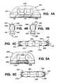
- FIG. 1is a cross sectional view of an exemplary embodiment of a tissue repair assembly of the present invention, implanted in a body tissue;
- FIG. 2Ais a side elevation view of an exemplary embodiment of a tissue repair assembly of the present invention, disposed on a delivery device of the present invention;
- FIGS. 2B and 2Care side elevation and top views, respectively, of a distal portion of the delivery tool illustrated in FIG. 2A ;
- FIGS. 3A-3Fare cross-sectional views of an exemplary embodiment of a method for repairing a tissue defect according to the present invention.
- FIGS. 4A-4Care respective top plan, end elevation and side elevation views of an exemplary embodiment of an fixation member of the present invention having three through openings for receiving suture;
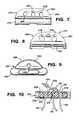
- FIGS. 5A-5Care top plan, end elevation and side elevation views of another embodiment of an fixation member of the present invention having two through openings for receiving suture;
- FIG. 6is a perspective view of a tissue repair assembly of the present invention employing the fixation members of FIGS. 4A-4C and FIGS. 5A-5C ;
- FIG. 7is a side elevation view of an alternative embodiment of an fixation member of the present invention having three through openings for receiving suture;
- FIG. 8is a side elevation view of an alternative embodiment of an fixation member of the present invention having two through openings for receiving suture;
- FIG. 9is a side elevation view of a further embodiment of an fixation member of the present invention having one through opening for receiving suture;
- FIG. 10is a cut-away view taken along lines 10 - 10 of FIG. 6 ;
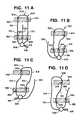
- FIGS. 11A-11Fare top cut-away views of further embodiments of tissue repair assemblies of the present invention.
- Devices and methods of the present inventionenable a surgeon to consistently and reliably repair tissue tears and separations using two fixation members interconnected by continuous segments of suture.
- Surgeries using the devices of the present inventionare performed without the surgeon having to tie any suture knots, and are particularly suitable for performing arthroscopic or endoscopic repairs.
- Repairs performed using the present inventionleave no knots, suture joints or other potential stress points along the suture interconnecting the fixation devices, reproducibly position any knots away from tissue areas that are particularly susceptible to post-surgical damage, for example, articulating tissue surfaces.
- FIG. 1schematically illustrates a cross sectional view of an exemplary embodiment of a tissue repair assembly 100 of the present invention implanted in a body tissue 102 , for repairing a defect 104 in the tissue 102 .
- the tissue 102is a meniscus in a knee and the defect 104 is a meniscal tear.
- the tissue 102is another type of body tissue.
- the defect 104is a separation between two different types of body tissue.
- the repair assembly 100is seen to comprise a first fixation member 106 , a second fixation member 108 and a continuous flexible element 110 interconnecting and extending through the first 106 and the second fixation member 108 .
- the flexible element 110can comprise any type of flexible element suitable for implantation and use in making surgical repairs, and is hereinafter referred to as “suture.”
- the suture 110can be any type of suture including suture fabricated using natural materials such as silk, and synthetic materials such as polyethylene terephthalate (PET) or other polyester materials.
- PETpolyethylene terephthalate
- the suture 110can be bioabsorbable, partially bioabsorbable, or nonabsorbable, and can have a circular cross section or another cross section. In one embodiment, the suture 110 is partially bioabsorbable, comprising polyethylene as a nonabsorbable component, and polydioxanone as a bioabsorbable component.
- the first fixation member 106is seen to comprise a first tissue-contact surface 112 , a first back surface 114 and a first 116 , a second 118 and a third through opening 120 between the first tissue-contact surface 112 and the first back surface 114 .
- the second fixation member 108is seen to comprise a second tissue contact surface 122 , a second back surface 124 and a respective first 126 and second through opening 128 between the respective tissue contact 122 and back surface 124 .
- one or more of the respective through openingsis adapted for slidably passing the suture 110 therethrough.
- the respective tissue contact and back surfaces between adjacent openings through each the first 106 and the second anchor 108are rounded to optimize the slidability of the suture 110 through and among the respective openings.
- the cross section of each of the openingsis round.
- one or more of the openingsis elongated in a direction transverse to a line connecting the one or more opening with an adjacent opening through the respective fixation member.
- the suture 110is seen to comprise a locking, sliding knot 120 adjacent to the back surface 114 of the first fixation member 106 .
- the sutureis seen to comprise a continuous loop section 132 extending from the locking, sliding knot 130 , the loop section 132 comprising a first limb 134 and a second limb 136 .
- the first limb 134is seen to extend from the locking, sliding knot 130 toward and through the respective first opening 116 in the first fixation member 106 from the respective back surface 114 to the respective tissue-contact surface 112 , toward and through the respective first opening 126 in the second fixation member 108 , from the respective tissue-contact surface 122 to the respective back surface 124 .
- the first limb 134is seen to be continuous with the second limb 136 in the loop 132 , returning through the respective second opening 128 from the back surface 124 to the tissue-contact surface 122 of the second fixation member 108 , toward and through the respective second opening 118 in the first fixation member 106 , to the locking, sliding knot 130 , completing the loop 132 .
- the loop 132is positioned slidably through each of the respective first and second opening through each of the first 106 and the second fixation member 108 .
- the second limb 136is connected fixedly to the locking, sliding knot 130 and the first limb 134 extends slidably through the locking, sliding knot 130 , to and continuous with a tensioning limb 138 that extends from the locking, sliding knot 130 toward and through the third opening 140 from the respective back side 114 to the tissue contact side 112 of the first anchor 106 .
- An application of tension to the tensioning limb 138 with respect to the first anchor 106is effective to slidingly draw suture from the loop 132 through the respective first opening in the first fixation member, the locking, sliding knot 130 and the third opening 120 , shortening the loop 132 as the transmitted tension further draws a portion of the second limb 136 slidingly through the respective second 128 and first opening 126 in the second fixation member 108 .
- shortening the loop 132applies a compressive force for closing the defect 104 in the tissue 102 . It is to be noted that for illustrative purposes in FIG.
- the various suture limbs 134 , 136 and 138are shown laterally separated from one another through the tissue 102 , but that in an actual tissue repair using the tissue repair assembly 100 , the various suture limbs 134 , 136 , 138 follow a substantially common path adjacent to one another through the tissue 102 .
- FIG. 2Aschematically illustrates a side view of an exemplary embodiment of the tissue repair assembly 100 , disposed on a delivery device 150 of the present invention, the delivery device 150 having a distal end 152 and a proximal end 154 .
- the delivery device 150is seen to comprise a substantially tubular distal delivery member 156 extending distally from a proximal handle 158 .
- FIGS. 2B and 2Cillustrate more detailed views of a distal portion of the delivery member 156 with the tissue repair assembly 100 disposed thereon, in respective side and top views.
- the first 106 and the second fixation member 108are seen to be slidably retained along and at least partially within the delivery member 156 .
- the delivery device 150is also seen to comprise at least one deployment rod 160 distally slidable in the delivery member 156 for sequentially expelling the first 106 and the second fixation member 108 distally from the delivery member 156 .
- the handle 158is seen to comprise at least one manually actuable trigger 162 , actuable for distally sliding one of the at least one deployment rod 160 .
- the delivery member 156comprises a curve 164 along its length. In another embodiment (not shown), the delivery member 156 is substantially straight between the handle 158 and the distal end 152 .
- each of the first 106 and the second fixation members 108is slidably retained in a longitudinal slot 166 in the delivery member 156 , the slot 166 extending proximally from the distal end 152 toward the handle 158 , and having opposing longitudinal edges 168 for slidably retaining the first 106 and the second fixation member 108 .
- the deployment rod 160initially rides underneath the second fixation member 108 outside of the lumen at the distal end of the delivery member 156 through which the rod 160 slides.
- a second trigger 163is engaged which causes a second deployment rod 161 to move distally and push the second fixation member 108 along the slot into a firing position (the position initially occupied by the first fixation member 106 ) within the lumen and ready to be deployed by the rod 160 when the trigger 162 is engaged.
- the delivery member 156terminates distally in a tissue-penetrating tip 170 .
- the delivery member 156terminates distally in a blunt tip.
- each of the first 106 and the second fixation member 108is retained on the delivery member 156 in an orientation that presents a minimum cross section of the respective fixation member for insertion into or through tissue along with the delivery member 156 .
- a resilient tube 172is shown in FIG. 2A positioned about the delivery member 156 .
- the resilient tube 172is fabricated from a resilient, transparent silicone material.
- the tube 172is omitted from FIGS. 2B and C for clarity.
- the resilient tubeis seen to be positioned about the delivery member 156 along a portion of the delivery member encompassing the locations along the delivery member 156 of the first 106 and the second 108 fixation member and at least a portion of the suture therebetween. Friction between the resilient tube 172 and the fixation members 106 , 108 and suture retained therein, retains the first 106 and the second fixation members 108 at predetermined longitudinal positions along the delivery member 156 before delivery of the respective fixation members to tissue.
- the resilient tube 172similarly provides suture management for the tissue repair assembly 100 by maintaining the suture along the delivery member.
- a distal end 174 of the resilient tube 172provides a soft depth stop for insertion of the delivery member 156 into tissue before deploying either or both of the first 106 and the second fixation member 108
- FIGS. 3A-3Fillustrate an exemplary embodiment of a method for repairing a tissue defect according to the present invention.
- the delivery member 156the tissue repair assembly 100 retained thereon, is seen to have been passed through a damaged body tissue 180 having a first tissue surface 182 and a second tissue surface 184 , to a first location 186 at the second tissue surface 184 , where the first fixation member 106 is seen to have been slidingly expelled from the distal end of the delivery member 156 , positioning the first fixation member 106 proximate to the first location 186 .
- the damaged body tissue 180is seen to comprise a tissue defect 188 .
- the first location 186is selected by the surgeon so that the completed repair will apply compression to the defect 188 .
- the tissue defect 188is a meniscal tear and the compression is effective to close the tear. It is to be noted that for illustrative purposes in FIG. 3A through FIG. 3F , as also noted for FIG. 1 hereinabove, various suture limbs extending from individual fixation members are shown laterally separated from one another through the tissue 180 between the first 182 and the second tissue surface 184 , but that in an actual tissue repair, the various suture limbs, follow a substantially common path adjacent to one another through the tissue 102 .
- the first fixation member 106can be expelled from the delivery member 156 within the material of the damaged body tissue 180 , or within or adjacent to a surface of another body tissue.
- the surgeonmay elect to pass the deployment member 156 to the first location 186 directly through the tissue defect 188 , adjacent to the tissue defect 188 , or through another area of tissue where the deployed tissue repair assembly 100 will be effective to apply compression across the tissue defect 188 .
- the delivery member 156is seen to have been retracted from the damaged body tissue 180 , leaving the first fixation member 106 proximate to the first location 186 .
- the first fixation member 106while slidably retained on the delivery member 156 , presents a minimum cross section for penetrating tissue.
- the first fixation member 106will toggle so that the respective tissue contact surface 112 lodges against the second tissue surface 184 at the first location 186 , presenting a maximum cross section of the first fixation device 106 to resist pullout through the damaged tissue 180 .
- the delivery member 156the second fixation member 108 still retained thereon, is seen to have been passed a second time through the damaged body tissue 180 , to a second location 190 at the second tissue surface 184 , where the second fixation member 108 is seen to have been slidingly expelled from the distal end of the delivery member 156 , positioning the second fixation member proximate to the second location 190 .
- the criteria by which the surgeon selects the second location 190 and the path of the delivery member 156 through tissueare parallel to the criteria used to select the first location 186 and the associated path through tissue.
- each of the first 186 and the second location 190is selected by the surgeon so that the completed repair will apply compression to the tissue defect 188 .
- the second fixation member 108can be expelled from the delivery member 156 within the material of the damaged body tissue 188 , or within or adjacent to a surface of another body tissue.
- the delivery member 156is seen to have been retracted from the damaged body tissue 188 , leaving the second fixation member 108 proximate to the second location, and leaving a portion of the suture loop 132 comprising the first suture limb 134 and the second limb 136 positioned adjacent a spanned section 192 of the first tissue surface 182 .
- the second fixation member 108while slidably retained on the delivery member 156 , presents a minimum cross section for penetrating tissue.
- the second fixation member 108Upon expulsion from the delivery member 156 , and in response to tension applied to one or both of the first limb 134 the second limb 136 , the second fixation member 108 toggles so that the respective tissue contact surface 122 lodges against the second tissue surface 184 at the second location 190 , presenting a maximum cross section of the second fixation device 108 to resist pullout through the damaged tissue 180 .
- the tensioning limb 138is seen to have been tensioned with respect to the first fixation member 106 , shortening the suture loop 132 and applying a compressive force to the tissue defect 188 .
- the tissue defect 188is a meniscal tear and the compressive force is effective to close the tear.
- the portion of the suture loop 132 adjacent the spanned section 192 of the first tissue surface 182remains substantially on the first tissue surface 182 after the tensioning.
- the tensioningcauses the suture comprising the loop 132 to locally compress the first tissue surface 182 , so that no suture is exposed above the remainder of the first tissue surface 182 with sufficient tensioning the suture comprising the loop 132 embeds into the damaged tissue 180 below the first tissue surface 182 , so that no suture is exposed above the remainder of the first tissue surface 182 .
- the tensioning limb 138is seen to have been trimmed at or below the first tissue surface 182 , leaving none of the tensioning limb 138 proud of the first tissue surface 182 .
- the damaged tissue 180is a meniscus of a knee
- the tissue defectis a meniscal tear
- the first tissue surface 182is the articulating surface of the meniscus
- the second tissue surface 184is the peripheral rim of the meniscus
- each of the first 106 and the second fixation member 108is deployed in the peripheral meniscal capsule.
- two or more tissue repair assemblies of the present inventionare used to repair a tissue defect, or to repair physically adjacent defects in a tissue.
- first and second locations for the respective first 106 and second fixation member 108is dependent on many factors including, but not limited to the type of tissue comprising the defect, the nature and extent of the defect, its location in the tissue, and its proximity to other tissues and other defects that may be present near the surgical site.
- the first and second locations for respective first and second fixation memberscan be on a single continuous surface of a damaged tissue.
- the first and the second locationare on opposite sides of a tissue defect along a tissue surface.
- the first and the second locationcan be on opposing tissue surfaces, the tissue defect therebetween.
- the first location and the second locationcould be on different tissues.
- FIGS. 4A-4Cschematically illustrate respective top, end and side views of an exemplary embodiment of a three-opening fixation member 200 of the present invention.
- the three-opening fixation member 200is the first fixation member 106 of the tissue repair assembly 100 disclosed hereinabove.
- the three-opening fixation member 200is seen to comprise a first body 202 having a respective first surface 204 , a respective second surface 206 , and three through openings comprising a first 208 , a second 210 , and a third opening 212 through the body 202 between the respective first surface 204 and second surface 206 .
- the three-opening fixation member 200is the first fixation member 106 , the respective first surface 204 is the tissue contact surface 112 and the respective second surface 206 is the back surface 114 .
- the three-opening fixation member 200is symmetrical about a plane 214 between the respective first 204 and second surface 206 .
- the respective first 204 and second surface 206can be asymmetrical about the plane 214 .
- Each of the three through openings 208 , 210 , 212 , and one or both of the respective first 204 and second surface 206 adjacent to and therebetweenis smoothly rounded to optimize slidability of suture through and between the openings.
- One or more of the three through openings 208 , 210 , 212is elongated in a direction perpendicular to a line interconnecting the one or more opening with an adjacent one of the three through openings. Elongation of the one or more opening enhances the slidability of suture through the respective opening.
- the first body 202is also seen to comprise a longitudinal groove 216 on each of the respective first 204 and second surface 206 . Each groove 216 is adapted to slidingly engage with one of the edges 168 of the longitudinal slot 166 in the delivery member 156 , to retain the three-opening fixation member 200 in the delivery member 156 .
- FIGS. 5A-5Cschematically illustrate respective top, end and side views of a further embodiment of a two-opening fixation member 220 of the present invention.
- the two-opening fixation member 220is the second fixation member 108 of the tissue repair assembly 100 disclosed hereinabove.
- the two-opening fixation member 220is seen to comprise a second body 222 having a respective first surface 224 , a respective second surface 226 , and two through openings comprising a respective first 228 and second opening 230 through the second body 222 between the respective first surface 224 and second surface 226 .
- the two-opening fixation member 220is the second fixation member 108 , the respective first surface 224 is the tissue contact surface 122 and the respective second surface 226 is the respective back surface 124 .
- the two-opening fixation member 220is symmetrical about a respective plane 232 between the respective first 224 and second surface 226 .
- the respective first 224 and second surface 226are asymmetrical about the respective plane 232 .
- the first 228 and the second through opening 230 in the two-opening fixation member and one or both of the respective first 224 and second surface 226 adjacent to and therebetweenare smoothly rounded to optimize slidability of suture through and between the openings.
- One or both of the two through openings 228 , 230can be elongated in a direction perpendicular to a line interconnecting the two through openings 228 , 230 to enhance slidability of suture through the respective openings.
- the second body 222is also seen to comprise a respective longitudinal groove 234 on each of the respective first 224 and second surface 226 . Each respective groove 234 is adapted to slidingly engage with one of the edges 168 of the longitudinal slot 166 in the delivery member 156 , to retain the two-opening fixation member 220 in the delivery member 156 .
- the three-opening fixation member 200 and the two-opening fixation member 220can be fabricated from any biocompatible material, and can be of the same, or of a different composition from one another.
- at least one of the fixation members 200 , 220is nonabsorbable.
- at least one of the fixation members 200 , 220is fabricated from polyetheretherketone (PEEK) polymer.
- PEEKpolyetheretherketone
- at least one of the fixation members 200 , 220is bioabsorbable.
- FIG. 6schematically illustrates a perspective view of an exemplary embodiment of a tissue repair assembly 250 of the present invention comprising the three-opening fixation member 200 and the two-opening fixation member 220 . It has the same construction as the tissue repair assembly 100 disclosed hereinabove, wherein the suture 110 comprises the locking, sliding knot 130 , the first 134 the second 136 and the tensioning limb 138 , the first 134 and the second limb 136 comprising the suture loop 132 .
- An engagement portion of the suture 110is positioned slidingly through the locking, sliding knot 130 at a location, hereinafter, a “post” 252 along the suture 110 , substantially adjacent to the respective second surface 206 of the first fixation member 200 , between the first 208 and the third opening 212 , the post 252 comprising a slidable transition between the first limb 134 and the tensioning limb 136 along the suture 110 .
- the locking, sliding knot 130locks the post 252 therein, substantially preventing the loop 132 from lengthening again. Locking, sliding knots are well known in the surgical art.
- the locking, sliding knotis a bunt line sliding knot, a type of locking, sliding knot known in the surgical arts, as well as in other arts such as nautical arts.
- itfurther comprises a stopper knot 254 to stabilize a suture tail 256 extending from the locking, sliding knot 130 .
- the stopper knot 254can comprise a single figure eight knot.
- the three-opening fixation member 200 and the two-opening fixation member 220are preferably each fabricated from PEEK, and the suture 110 is a partially bioabsorbable, high strength suture comprising ultra high molecular weight polyethylene (UHMWPE) and polydioxanone (PDS). More preferably, the UHMWPE and PDS suture is an OrthocordTM suture, distributed by Depuy Mitek, of Raynham, Mass.
- UHMWPEultra high molecular weight polyethylene
- PDSpolydioxanone
- FIG. 7 through FIG. 9schematically illustrate top views of various alternative embodiments of fixation members that can comprise tissue repair assemblies of the present invention.
- FIG. 7illustrates a top view another embodiment of a three-opening fixation member 260 that resembles the fixation member 200 of FIGS. 4A-4C and FIG. 6 , except that in the three-opening fixation member 260 illustrated in FIG. 7 , each of three openings 262 , 264 , 266 through a respective body 268 between a respective first 270 and second surface 272 , are circular in cross section.
- FIG. 8illustrates a top view another embodiment of a two-opening fixation member 274 that resembles the fixation member 220 of FIGS. 5A-5C and FIG. 6 , except that in the two-opening fixation member 274 illustrated in FIG. 8 , each of two openings 276 , 278 through a respective body 280 between a respective first 282 and second surface 284 are circular in cross section.
- FIG. 9schematically illustrates an embodiment of a single-opening fixation member 286 of the present invention.
- the single-opening fixation member 286is seen to resemble the two-opening fixation member 274 and the three-opening fixation member 260 , but having only a single opening 288 through a respective body 290 between a respective first 292 and second surface 294 .
- the two-opening fixation member 220is replaced with the single-opening fixation member 286 , and a suture loop extending between the three-opening fixation member 200 and the single opening fixation member 286 , is positioned through the single opening 288 .
- a suture loop extending from a substantially three-opening fixation membercomprises two or more fixation members therealong, through each of which the suture loop is positioned.
- sutureis passed substantially in one longitudinal direction only through a locking, sliding element (a restriction element) associated with a fixation member from which three limbs of suture extend.
- the restriction elementcan be any type of restriction element through which suture can pass in a preferred longitudinal direction, and is restricted from passing in an opposite longitudinal direction.
- the restriction elementis a locking, sliding suture knot.
- the restriction elementcomprises one or more opening in the fixation member adapted to pass a barbed suture having a preferred direction of sliding through the one or more opening.
- the restriction elementis a unidirectional passage through or around the fixation member itself.
- FIG. 10schematically illustrates a cross sectional side view of a portion of the tissue repair assembly 250 of FIG. 6 , showing a cross-sectional view of the three-opening fixation member 200 , and the portion of a the suture 110 positioned therethrough, with the locking, sliding knot 130 lodged against the second surface 206 .
- the internal surfaces of the three openings 208 , 210 , 212 through the three-opening fixation member 200 and the portions of the respective first 204 and second surface 206 therebetweenare seen to be rounded to optimize sliding of the suture 110 therethrough and therealong, respectively.
- Tissue repair assemblies of the present inventioncan be constructed in a variety of configurations, comprising fixation members of any size and proportions suited to repairing a particular tissue defect, selection of the size and type of suture used, and variations in the routing of suture with respect to the fixation members.
- the number of through openings required in fixation members used to construct a tissue repair assembly of the present inventionis in turn selected based on the routing of the suture.
- FIGS. 11A-11Fschematically illustrate various alternative embodiments of tissue repair assemblies of the present invention, differing in configuration from the embodiments illustrated hereinabove with regard to one or both of suture routing between two fixation members, and the number of openings provided through the respective fixation members. It is to be noted that the total number of openings provided through any of the fixation members disclosed herein can exceed the number of openings required for a particular suture routing without deviating from the intent or scope of the present invention.
- FIG. 11Aillustrates a first alternative embodiment tissue repair assembly 300 comprising a first fixation member 302 and a second fixation member 304 .
- the tissue repair assembly 300 of FIG. 11Ais also seen to comprise a length of suture 306 and a restriction element 308 .
- the restriction element 308is a locking, sliding knot formed from the suture 306 .
- the length of suture 306further comprises a first limb 310 continuous with a second limb 312 , the first 310 and the second limb 312 together comprising a suture loop 314 connecting the first 302 to the second fixation member 304 .
- the second limb 312is substantially fixedly connected to the restriction member 308 .
- the second limb 312extends through the restriction member 308 and is continuous with a suture tail 316 that is terminated by a stopper knot 318 as disclosed hereinabove.
- the first limb 310is routed slidingly through the restriction member 308 and is continuous with a tensioning limb 320 .
- sutureis routed through one or more opening through various fixation members.
- the sutureis generally slidingly routed through the one or more opening to ensure smooth operation of the assembly, for deploying the respective fixation members in tissue, and for sliding suture through the assembly to approximate a tissue defect.
- the various alternative embodiments illustrated in each of FIG. 11A through FIG. 11Fcomprise the length of suture 306 and components thereof, but vary in their routing about and between respective first and second fixation members.
- the first fixation member 302is seen to comprise a first 322 , a second 324 and a third opening 326 therethrough.
- the second fixation member 304is seen to comprise two openings 328 , 330 therethrough.
- the suture loop 314is seen to be routed through each of the two openings 328 , 330 in the second fixation member 304 .
- the first limb 310is seen to be routed through the first opening 322 in the first fixation member 302 and to the restriction element 308 .
- the second limb 312is seen to be routed through the third opening 326 in the first fixation member 302 , and to the restriction element 308 .
- the tensioning limb 320is seen to be routed from the restriction element 308 and through the second opening 324 in the first fixation member 302 .
- Tension applied to the tensioning limb 320 with respect to the first fixation member 302is effective to draw suture through the restriction member 308 , thereby decreasing the size of the loop 314 .
- the tissue repair assembly 300is seen to resemble the tissue repair assemblies 100 , 250 disclosed hereinabove, except that in the embodiment of FIG. 11A , the tensioning limb 320 is routed through a central opening in the respective fixation member 302 , as opposed to being routed through a differently positioned in the earlier disclosed tissue repair assemblies 100 , 250 .
- FIG. 11Billustrates a second alternative embodiment of a tissue repair assembly 332 comprising the first 302 and the second fixation member 304 of the embodiment of FIG. 11A , but differing in the suture routing about and through the first fixation member 302 , and in construction of the restriction element 308 .
- the restriction element 308is a locking, sliding suture knot affixed to the first fixation element 302 by the suture tail 316 being routed through the third opening 326 in the first fixation device 302 and secured therethrough by the stopper knot 318 .
- Each of the first 310 and the second limbs of suture 312are seen to be routed through one of the first 322 and the second openings 324 in the first fixation member 302 .
- the tensioning limb 320is seen to be routed around the first fixation member 302 , as opposed to being routed through an opening in the first fixation member 302 , as illustrated for the first alternative embodiment of the tissue repair assembly 300 illustrated in FIG. 11A .
- FIG. 11Cillustrates a third alternative embodiment of a tissue repair assembly 334 .
- the tissue repair assembly 334 of FIG. 11Cis seen to comprise a first fixation member 336 having a first 338 and a second opening 340 therethrough.
- the tissue repair assembly 334is also seen to comprise a second fixation member 342 having a single opening 344 therethrough.
- the suture loop 314is seen to be routed through the single opening 344 in the second fixation member 342 , and each of the first 310 and the second limb 312 of suture is seen to be routed through one of the first 338 and the second opening 340 in the first fixation member 336 .
- the tensioning limb 320is seen to be routed around the first fixation member 336 .
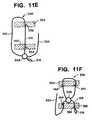
- FIG. 11DA fourth alternative embodiment of a tissue repair assembly 346 is illustrated in FIG. 11D .
- the tissue repair assembly 346 illustrated in FIG. 11Dresembles the tissue repair assembly 334 illustrated in FIG. 11C , except that in the embodiment illustrated in FIG. 11D , the tensioning limb 320 is routed from the restriction element 314 , through the second opening 340 in the first fixation member 336 .
- one of the first 310 and the second limb of suture 312is seen to be routed through the first opening 338 in the first fixation member 336
- the other of the first 310 and the second limb of suture 312is seen to be routed around the first fixation member 336 .
- FIG. 11Eillustrates a fifth alternative embodiment of a tissue repair assembly 348 comprising a first 350 and a second fixation member 352 each having a single respective opening 354 , 356 therethrough.
- the suture loop 320is seen to be routed through the single opening 356 in the second fixation member 352 .
- One of the first 310 and the second limb of suture 312is seen to be routed through the single opening 354 in the first fixation member 350
- the other of the first 310 and the second limb of suture 312is seen to be routed around the first fixation member 350 .
- the tensioning limb 320is seen to be routed around the first fixation member 350 .
- FIG. 11Fillustrates a sixth alternative embodiment of a tissue repair assembly 358 comprising a first 360 and a second fixation member 362 , each having two respective openings 364 , 366 , 368 , 370 therethrough.
- the suture loop 314is seen to be routed through each of the two openings 368 , 370 in the second fixation member 362 and each of the first 310 and the second suture limb 312 is routed directly to the restriction member 308 , which is positioned adjacent to the first fixation member 360 , between the first 360 and the second fixation member 362 .
- the restriction element 308is a locking, sliding suture knot affixed to the first fixation member 360 by the suture tail 316 being routed through one 366 of the two respective openings 364 , 366 in the first fixation device 360 and secured therethrough by the stopper knot 318 .
- the tensioning limb 320is seen to be routed through the other 364 of the two respected openings 364 , 366 in the first fixation device 360 .
- any of the embodiments of respective second fixation memberscan be combined with any of the embodiments of respective first fixation members, associated restriction elements and suture routing to provide additional embodiments within the intent and scope if the present invention.
- Tissue repair assemblies and methods of the present inventionhave several advantages.
- a meniscal repair procedure using a tissue repair assembly of the present inventioncan provide a finished tissue repair where only suture, no hard bodies or knots, are left on the articulating (that surface facing the femur) surface of the meniscus in the knee, thus supporting healing and minimizing the probability that articulating cartilage contacting the meniscus will be damaged when the patient flexes the knee joint after the surgery.
- the repairscan be performed in any orientation with respect to a damaged tissue and the associated tissue defect.
- Tissue repair assemblies of the present inventionprovide additional flexibility for the surgeon because the tissue repair assemblies include no fixed lengths of suture to limit the relative locations of the two tissue fixation members.
- tissue repair assemblies of the present inventiondo not restrict the minimum distance between the two fixation members.
- tissue repair assemblies of the present inventionan entire meniscal repair can be performed from the articulating side of the meniscus, an approach that minimizes surgical trauma to surrounding tissue.
- Another advantageis that the strength and stability of a repair performed using tissue repair assemblies of the present invention is provided by two uninterrupted, continuous limbs of suture, the limbs including no joints, knots, or retainers therealong between first and second anchoring members. Further advantageously, providing two sutures that completely span the anchoring locations provides superior distribution of forces on the repaired tissue, relative to single, knotted or joined suture segments spanning the anchoring locations.
- Tissue repair assemblies of the present inventionare also very versatile in their application, including applicability to meniscal repairs, approximation of partial shoulder rotator cuff tears, and any other soft tissue repair where two tissues, or damage within a tissue, requires surgical approximation.
- the tissue repair assembliescould be used to anchor soft tissue to bone
Landscapes
- Health & Medical Sciences (AREA)
- Surgery (AREA)
- Life Sciences & Earth Sciences (AREA)
- Medical Informatics (AREA)
- Nuclear Medicine, Radiotherapy & Molecular Imaging (AREA)
- Engineering & Computer Science (AREA)
- Biomedical Technology (AREA)
- Heart & Thoracic Surgery (AREA)
- Molecular Biology (AREA)
- Animal Behavior & Ethology (AREA)
- General Health & Medical Sciences (AREA)
- Public Health (AREA)
- Veterinary Medicine (AREA)
- Rheumatology (AREA)
- Surgical Instruments (AREA)
- Prostheses (AREA)
Abstract
Description
Claims (28)
Priority Applications (5)
| Application Number | Priority Date | Filing Date | Title |
|---|---|---|---|
| US12/609,448US8790369B2 (en) | 2009-07-24 | 2009-10-30 | Apparatus and method for repairing tissue |
| US14/306,299US9421012B2 (en) | 2009-07-24 | 2014-06-17 | Apparatus and method for repairing tissue |
| US15/236,824US10149675B2 (en) | 2009-07-24 | 2016-08-15 | Apparatus and method for repairing tissue |
| US16/214,236US11071537B2 (en) | 2009-07-24 | 2018-12-10 | Apparatus and method for repairing tissue |
| US17/384,899US20210346009A1 (en) | 2009-07-24 | 2021-07-26 | Apparatus and method for repairing tissue |
Applications Claiming Priority (2)
| Application Number | Priority Date | Filing Date | Title |
|---|---|---|---|
| US22839609P | 2009-07-24 | 2009-07-24 | |
| US12/609,448US8790369B2 (en) | 2009-07-24 | 2009-10-30 | Apparatus and method for repairing tissue |
Related Child Applications (1)
| Application Number | Title | Priority Date | Filing Date |
|---|---|---|---|
| US14/306,299DivisionUS9421012B2 (en) | 2009-07-24 | 2014-06-17 | Apparatus and method for repairing tissue |
Publications (2)
| Publication Number | Publication Date |
|---|---|
| US20110022061A1 US20110022061A1 (en) | 2011-01-27 |
| US8790369B2true US8790369B2 (en) | 2014-07-29 |
Family
ID=43016114
Family Applications (5)
| Application Number | Title | Priority Date | Filing Date |
|---|---|---|---|
| US12/609,448Active2032-09-14US8790369B2 (en) | 2009-07-24 | 2009-10-30 | Apparatus and method for repairing tissue |
| US14/306,299ActiveUS9421012B2 (en) | 2009-07-24 | 2014-06-17 | Apparatus and method for repairing tissue |
| US15/236,824ActiveUS10149675B2 (en) | 2009-07-24 | 2016-08-15 | Apparatus and method for repairing tissue |
| US16/214,236Active2030-12-12US11071537B2 (en) | 2009-07-24 | 2018-12-10 | Apparatus and method for repairing tissue |
| US17/384,899AbandonedUS20210346009A1 (en) | 2009-07-24 | 2021-07-26 | Apparatus and method for repairing tissue |
Family Applications After (4)
| Application Number | Title | Priority Date | Filing Date |
|---|---|---|---|
| US14/306,299ActiveUS9421012B2 (en) | 2009-07-24 | 2014-06-17 | Apparatus and method for repairing tissue |
| US15/236,824ActiveUS10149675B2 (en) | 2009-07-24 | 2016-08-15 | Apparatus and method for repairing tissue |
| US16/214,236Active2030-12-12US11071537B2 (en) | 2009-07-24 | 2018-12-10 | Apparatus and method for repairing tissue |
| US17/384,899AbandonedUS20210346009A1 (en) | 2009-07-24 | 2021-07-26 | Apparatus and method for repairing tissue |
Country Status (6)
| Country | Link |
|---|---|
| US (5) | US8790369B2 (en) |
| EP (1) | EP2277456B1 (en) |
| JP (1) | JP5769938B2 (en) |
| CN (2) | CN101961256A (en) |
| AU (2) | AU2010202954A1 (en) |
| CA (1) | CA2710909A1 (en) |
Cited By (25)
| Publication number | Priority date | Publication date | Assignee | Title |
|---|---|---|---|---|
| US9757116B2 (en) | 2012-05-07 | 2017-09-12 | Medos International Sárl | Systems, devices, and methods for securing tissue |
| US9763655B2 (en) | 2012-09-20 | 2017-09-19 | Medos International Sarl | Systems, devices, and methods for securing tissue using hard anchors |
| US9795373B2 (en) | 2012-05-07 | 2017-10-24 | Medos International Sàrl | Systems, devices, and methods for securing tissue using a suture having one or more protrusions |
| US9833229B2 (en) | 2010-12-23 | 2017-12-05 | Medos International Sàrl | Adjustable anchor systems and methods |
| US9872678B2 (en) | 2012-03-30 | 2018-01-23 | Medos International Sarl | Surgical filament assemblies |
| US9895145B2 (en) | 2010-11-23 | 2018-02-20 | Medos International Sàrl | Surgical filament snare assemblies |
| US9949732B2 (en) | 2005-02-07 | 2018-04-24 | Ivy Sports Medicine, Llc | System and method for all-inside suture fixation for implant attachment and soft tissue repair |
| US20190015091A1 (en)* | 2017-07-12 | 2019-01-17 | Ethicon, Inc. | Systems, devices and methods for delivering transfascial suture implants for securing surgical mesh to tissue |
| US10245169B2 (en)* | 2014-06-20 | 2019-04-02 | Endo Tools Therapeutics S.A. | Assembly for securing gastrointestinal tissue folds |
| US10258321B2 (en) | 2012-12-27 | 2019-04-16 | Medos International Sàrl | Surgical constructs and methods for securing tissue |
| US10271833B2 (en) | 2012-05-07 | 2019-04-30 | Medos International Sàrl | Systems, devices, and methods for securing tissue using snare assemblies and soft anchors |
| US10292695B2 (en) | 2010-11-23 | 2019-05-21 | Medos International Sàrl | Surgical filament snare assemblies |
| US10548590B2 (en) | 2005-02-07 | 2020-02-04 | Ivy Sports Medicine, Llc | System and method for all-inside suture fixation for implant attachment and soft tissue repair |
| US10603028B2 (en) | 2017-06-14 | 2020-03-31 | Medos International Sarl | Finger traps for collapsible suture loops |
| US10631848B2 (en) | 2013-03-15 | 2020-04-28 | Medos International Sàrl | Surgical constructs with collapsing suture loop and methods for securing tissue |
| US10653409B2 (en) | 2015-12-04 | 2020-05-19 | Crossroads Extremity Systems, Llc | Devices and methods for anchoring tissue |
| WO2020118087A1 (en)* | 2018-12-05 | 2020-06-11 | Paragon 28, Inc. | Soft tissue implant systems, instruments and related methods |
| US10758224B2 (en) | 2017-03-27 | 2020-09-01 | Trimed, Incorporated | System and method controlling a relationship between first and second bodies on a person |
| US10932769B2 (en) | 2016-05-26 | 2021-03-02 | Ivy Sports Medicine, Llc | System and method for all-inside suture fixation for implant attachment and soft tissue repair |
| US11337689B2 (en)* | 2020-08-31 | 2022-05-24 | Yoon Ho CHUNG | Benign prostatic hyperplasia treatment device |
| US20220249219A1 (en)* | 2020-08-31 | 2022-08-11 | Yoon Ho CHUNG | Benign prostatic hyperplasia treatment device |
| US11419599B2 (en) | 2016-04-20 | 2022-08-23 | Medos International Sarl | Meniscal repair devices, systems, and methods |
| US11534154B2 (en) | 2017-08-31 | 2022-12-27 | Medos International Sarl | Devices and methods for tissue repair |
| US20240315689A1 (en)* | 2016-11-03 | 2024-09-26 | Smith & Nephew, Inc. | Tissue repair assembly and system with soft anchoring implant |
| US12433581B2 (en) | 2021-08-23 | 2025-10-07 | Arthrex, Inc. | Tensionable interconnected anchors with double punch inserter |
Families Citing this family (86)
| Publication number | Priority date | Publication date | Assignee | Title |
|---|---|---|---|---|
| US7972337B2 (en) | 2005-12-28 | 2011-07-05 | Intrinsic Therapeutics, Inc. | Devices and methods for bone anchoring |
| EP1624832A4 (en)* | 1999-08-18 | 2008-12-24 | Intrinsic Therapeutics Inc | Devices and method for augmenting a vertebral disc nucleus |
| US7094258B2 (en)* | 1999-08-18 | 2006-08-22 | Intrinsic Therapeutics, Inc. | Methods of reinforcing an annulus fibrosis |
| US8323341B2 (en) | 2007-09-07 | 2012-12-04 | Intrinsic Therapeutics, Inc. | Impaction grafting for vertebral fusion |
| US7553329B2 (en)* | 1999-08-18 | 2009-06-30 | Intrinsic Therapeutics, Inc. | Stabilized intervertebral disc barrier |
| US7717961B2 (en)* | 1999-08-18 | 2010-05-18 | Intrinsic Therapeutics, Inc. | Apparatus delivery in an intervertebral disc |
| CA2425951C (en)* | 1999-08-18 | 2008-09-16 | Intrinsic Therapeutics, Inc. | Devices and method for nucleus pulposus augmentation and retention |
| US7998213B2 (en)* | 1999-08-18 | 2011-08-16 | Intrinsic Therapeutics, Inc. | Intervertebral disc herniation repair |
| US7722644B2 (en) | 2003-06-11 | 2010-05-25 | Medicine Lodge, Inc. | Compact line locks and methods |
| JP2007515988A (en)* | 2003-06-20 | 2007-06-21 | イントリンジック セラピューティックス インコーポレイテッド | Device and method for delivering an implant from an annular defect of an intervertebral disc |
| US9314234B2 (en) | 2007-07-03 | 2016-04-19 | Ceterix Orthopaedics, Inc. | Pre-tied surgical knots for use with suture passers |
| US9861354B2 (en) | 2011-05-06 | 2018-01-09 | Ceterix Orthopaedics, Inc. | Meniscus repair |
| US10441273B2 (en) | 2007-07-03 | 2019-10-15 | Ceterix Orthopaedics, Inc. | Pre-tied surgical knots for use with suture passers |
| US8465505B2 (en) | 2011-05-06 | 2013-06-18 | Ceterix Orthopaedics, Inc. | Suture passer devices and methods |
| US9211119B2 (en) | 2007-07-03 | 2015-12-15 | Ceterix Orthopaedics, Inc. | Suture passers and methods of passing suture |
| US20110196492A1 (en)* | 2007-09-07 | 2011-08-11 | Intrinsic Therapeutics, Inc. | Bone anchoring systems |
| US9717581B2 (en)* | 2009-02-05 | 2017-08-01 | Coloplast A/S | Incontinence treatment device including a system of anchors |
| US8864797B2 (en)* | 2009-07-02 | 2014-10-21 | Coorstek Medical Llc | Systems and methods for intra-operative tension and fixation of zipknot ACL fixation |
| US9011454B2 (en)* | 2009-11-09 | 2015-04-21 | Ceterix Orthopaedics, Inc. | Suture passer with radiused upper jaw |
| US9848868B2 (en) | 2011-01-10 | 2017-12-26 | Ceterix Orthopaedics, Inc. | Suture methods for forming locking loops stitches |
| US11744575B2 (en) | 2009-11-09 | 2023-09-05 | Ceterix Orthopaedics, Inc. | Suture passer devices and methods |
| US10010439B2 (en)* | 2010-06-13 | 2018-07-03 | Synerz Medical, Inc. | Intragastric device for treating obesity |
| US9913638B2 (en) | 2011-01-10 | 2018-03-13 | Ceterix Orthopaedics, Inc. | Transosteal anchoring methods for tissue repair |
| US8795334B2 (en) | 2011-01-28 | 2014-08-05 | Smith & Nephew, Inc. | Tissue repair |
| US8926661B2 (en)* | 2011-06-02 | 2015-01-06 | Smith & Nephew, Inc. | Surgical fastening |
| US9198648B2 (en) | 2011-06-20 | 2015-12-01 | Ethicon, Inc. | Method and device for approximating tissue |
| US10667895B2 (en)* | 2011-06-30 | 2020-06-02 | Boston Scientific Scimed, Inc. | Implants, tools, and methods for treatments of pelvic conditions |
| US9192368B2 (en) | 2011-08-04 | 2015-11-24 | Smith & Nephew, Inc. | Suspension device to anchor tissue graft |
| US10524778B2 (en) | 2011-09-28 | 2020-01-07 | Ceterix Orthopaedics | Suture passers adapted for use in constrained regions |
| US9492162B2 (en) | 2013-12-16 | 2016-11-15 | Ceterix Orthopaedics, Inc. | Automatically reloading suture passer devices and methods |
| TWI481380B (en)* | 2011-12-15 | 2015-04-21 | Pergolas Medical Technology | Minimally invasive tendon suturing surgical kit |
| US9439644B2 (en) | 2011-12-20 | 2016-09-13 | Medos International Sàrl | Systems and methods for repairing tissue |
| US9084597B2 (en)* | 2012-03-09 | 2015-07-21 | Smith & Nephew, Inc. | Suture-based knotless repair |
| US9517060B2 (en) | 2012-09-27 | 2016-12-13 | Ethicon, Inc. | Method and device for approximating tissue |
| US8986327B2 (en) | 2012-10-18 | 2015-03-24 | Smith & Nephew, Inc. | Flexible anchor delivery system |
| US10111651B2 (en) | 2012-11-02 | 2018-10-30 | Coloplast A/S | System and method of anchoring support material to tissue |
| US20140128913A1 (en)* | 2012-11-02 | 2014-05-08 | Coloplast A/S | Surgical system including an anchor insertable into a cannula of an introducer |
| US9795426B2 (en)* | 2013-03-07 | 2017-10-24 | DePuy Synthes Products, Inc. | Implants |
| US10052094B2 (en) | 2013-03-11 | 2018-08-21 | Medos International Sàrl | Implant having adjustable filament coils |
| US9974643B2 (en) | 2013-03-11 | 2018-05-22 | Medos International Sàrl | Implant having adjustable filament coils |
| US12064329B2 (en)* | 2013-03-15 | 2024-08-20 | Boston Scientific Scimed, Inc. | Surgical implant system and method |
| AU2014228420B2 (en) | 2013-03-15 | 2018-11-08 | Smith & Nephew, Inc. | Surgical fastening |
| WO2014190080A1 (en)* | 2013-05-21 | 2014-11-27 | Ams Research Corporation | Surgical implant system and method |
| CN109394320B (en)* | 2013-07-30 | 2021-12-31 | 阿库洛医药有限公司 | Ligation device, kit and method |
| US9757113B2 (en) | 2013-07-31 | 2017-09-12 | Medos International Sàrl | Adjustable graft fixation device |
| US9480546B2 (en) | 2013-08-05 | 2016-11-01 | Coloplast A/S | Hysteropexy mesh apparatuses and methods |
| US9247935B2 (en) | 2013-09-23 | 2016-02-02 | Ceterix Orthopaedics, Inc. | Arthroscopic knot pusher and suture cutter |
| US10405968B2 (en) | 2013-12-11 | 2019-09-10 | Medos International Sarl | Implant having filament limbs of an adjustable loop disposed in a shuttle suture |
| US20150282803A1 (en)* | 2014-04-02 | 2015-10-08 | Vishal M. Mehta | Surgical device for repairing tissue |
| CN204951031U (en) | 2014-04-08 | 2016-01-13 | 赛特里克斯整形公司 | Ware device is worn to draw by suture |
| JP6661600B2 (en)* | 2014-07-18 | 2020-03-11 | エシコン・インコーポレイテッドEthicon, Inc. | Mechanical retraction by mooring for lung volume reduction |
| CN104274220B (en)* | 2014-10-22 | 2017-01-18 | 陕西福泰医疗科技有限公司 | Fastening device for memory alloy suture line |
| US9687223B2 (en) | 2014-12-04 | 2017-06-27 | Coloplast A/S | Tissue anchor system |
| US10226245B2 (en) | 2015-07-21 | 2019-03-12 | Ceterix Orthopaedics, Inc. | Automatically reloading suture passer devices that prevent entanglement |
| US20170027617A1 (en)* | 2015-07-31 | 2017-02-02 | Intrepid Orthopedics | Odontoid bullet |
| US10405853B2 (en) | 2015-10-02 | 2019-09-10 | Ceterix Orthpaedics, Inc. | Knot tying accessory |
| EP4241697A3 (en)* | 2015-10-21 | 2024-01-17 | Coremedic AG | Medical implant for heart valve repair |
| US10251639B1 (en) | 2015-11-20 | 2019-04-09 | Ronald Yamada | Meniscus repair system |
| US10085830B2 (en)* | 2016-05-13 | 2018-10-02 | Medos International Sarl | Device, system, and method for delivery of a tissue fixation device |
| US20180049734A1 (en)* | 2016-08-16 | 2018-02-22 | Conmed Corporation | Method and Device for Securing Suture to an Anchor Body of a Suture Anchor |
| CN108201455B (en)* | 2018-01-23 | 2023-07-18 | 上海利格泰生物科技股份有限公司 | Suture orifice mechanism and threading system |
| WO2020069486A1 (en)* | 2018-09-28 | 2020-04-02 | Conmed Corporation | System for repairing soft tissue tears |
| CN109350151B (en)* | 2018-11-29 | 2024-05-17 | 北京天星医疗股份有限公司 | A meniscus suture device |
| EP3905967A4 (en)* | 2019-01-04 | 2022-10-05 | The Texas A&M University System | Approximating anchor device |
| FR3094625A1 (en)* | 2019-04-02 | 2020-10-09 | Jean-Luc Raynier | Device for reinserting soft tissue to a bone support |
| FR3095586B1 (en)* | 2019-05-05 | 2023-09-29 | Missana Marie Christine | BREAST IMPLANT WITH A FIXATION CLIP |
| CN111557701B (en)* | 2019-05-10 | 2024-09-20 | 华中科技大学同济医学院附属协和医院 | A meniscus repair suture puncture needle |
| US12295563B2 (en)* | 2019-10-09 | 2025-05-13 | Board Of Supervisors Of Louisiana State University And Agricultural And Mechanical College | Button for anchoring of multiple sutures |
| US12194575B2 (en) | 2020-01-13 | 2025-01-14 | Milwaukee Electric Tool Corporation | Portable battery pack-powered welder |
| USD980424S1 (en) | 2020-04-29 | 2023-03-07 | Coloplast A/S | Tissue anchor |
| US11944288B2 (en) | 2020-04-29 | 2024-04-02 | Coloplast A/S | Tissue anchor system including a fixation device and a delivery tool |
| JP7736699B2 (en) | 2020-04-30 | 2025-09-09 | アキュームド・エルエルシー | Friction-reduced knotless suture routing |
| US20220280148A1 (en)* | 2021-03-03 | 2022-09-08 | Carilion Clinic | Soft tissue fixation devices and methods |
| CN113057699B (en)* | 2021-03-12 | 2022-09-02 | 杭州锐健马斯汀医疗器材有限公司 | Implant, implant forming method, and suture instrument |
| AU2022254721B2 (en)* | 2021-04-08 | 2024-12-12 | Integrity Orthopaedics, Inc. | Cartridge device for suture anchor and suture management during implantation of a micro suture anchor array |
| CA3214365A1 (en)* | 2021-04-08 | 2022-10-13 | Integrity Orthopaedics, Inc. | Tensionable and lockable micro suture anchors and anchor arrays for anatomical attachment of soft tissue to bone |
| US11382611B1 (en)* | 2021-04-08 | 2022-07-12 | Integrity Orthopaedics, Inc. | Knotless micro-suture anchors and anchor arrays for anatomical attachment of soft tissue to bone |
| US11389154B1 (en)* | 2021-04-08 | 2022-07-19 | Integrity Orthopaedics, Inc. | Knotless micro suture anchor array for high density anatomical attachment of soft tissue to bone |
| US20220323198A1 (en)* | 2021-04-08 | 2022-10-13 | Integrity Orthopaedics, Inc. | Tensionable and lockable micro suture anchors and anchor arrays for anatomical attachment of soft tissue to bone |
| US11375992B1 (en)* | 2021-04-08 | 2022-07-05 | Integrity Orthopaedics, Inc. | Cartridge device for suture anchor and suture management during implantation of a micro suture anchor array |
| US11382613B1 (en)* | 2021-04-08 | 2022-07-12 | Integrity Orthopaedics, Inc. | Methods for transtendinous implantation of knotless micro suture anchors and anchor arrays |
| US11375995B1 (en)* | 2021-04-08 | 2022-07-05 | Integrity Orthopaedics, Inc. | Locking suture construct for tensioned suture to suture stitches in anchor arrays for attaching soft tissue to bone |
| US12226307B2 (en)* | 2021-04-08 | 2025-02-18 | Integrity Orthopaedics, Inc. | Individually lockable cinch loop micro suture anchor array for high density anatomical attachment of soft tissue to bone |
| US12426871B2 (en) | 2022-08-24 | 2025-09-30 | Globus Medical, Inc. | Systems, devices and methods for implanting suture buttons |
| CN115778457A (en)* | 2022-11-10 | 2023-03-14 | 上海利格泰生物科技有限公司 | A bone implant, positioning sleeve, inserter and implantation system |
| CN119632735A (en)* | 2024-11-08 | 2025-03-18 | 常州市第一人民医院 | A meniscus implant |
Citations (45)
| Publication number | Priority date | Publication date | Assignee | Title |
|---|---|---|---|---|
| US233475A (en) | 1880-10-19 | l vandermark | ||
| US261501A (en) | 1882-07-18 | Bag and sail tie | ||
| US4235238A (en) | 1978-05-11 | 1980-11-25 | Olympus Optical Co., Ltd. | Apparatus for suturing coeliac tissues |
| US5085661A (en) | 1990-10-29 | 1992-02-04 | Gerald Moss | Surgical fastener implantation device |
| US5320633A (en) | 1992-12-10 | 1994-06-14 | William C. Allen | Method and system for repairing a tear in the meniscus |
| US5467786A (en) | 1992-12-10 | 1995-11-21 | William C. Allen | Method for repairing tears and incisions in soft tissue |
| US5470337A (en) | 1994-05-17 | 1995-11-28 | Moss; Gerald | Surgical fastener |
| US5549631A (en) | 1993-05-14 | 1996-08-27 | Bonutti; Peter M. | Method of closing discontinuity in tissue |
| US5601571A (en) | 1994-05-17 | 1997-02-11 | Moss; Gerald | Surgical fastener implantation device |
| US5643319A (en) | 1991-05-13 | 1997-07-01 | United States Surgical Corporation | Device for applying a meniscal staple |
| US5810848A (en) | 1996-08-21 | 1998-09-22 | Hayhurst; John O. | Suturing system |
| US5891168A (en) | 1997-01-31 | 1999-04-06 | Thal; Raymond | Process for attaching tissue to bone using a captured-loop knotless suture anchor assembly |
| US6056320A (en) | 1998-10-23 | 2000-05-02 | Chrysler Corporation | Energy absorbing occupant restraint system |
| US6126578A (en) | 1998-01-02 | 2000-10-03 | Lapointe; Brian | Jumping device having a flexible tether and method of using the jumping device |
| US6143006A (en) | 1998-04-18 | 2000-11-07 | Chan; Kwan-Ho | Apparatus and method for tying and tensioning knots |
| US6306159B1 (en) | 1998-12-23 | 2001-10-23 | Depuy Orthopaedics, Inc. | Meniscal repair device |
| US20020019649A1 (en) | 1999-12-02 | 2002-02-14 | Smith & Nephew, Inc., Delaware Corporation | Closure device and method for tissue repair |
| US6500184B1 (en) | 2001-01-31 | 2002-12-31 | Yung C. Chan | Suturing apparatus and method of suturing |
| US20030130694A1 (en) | 1999-12-02 | 2003-07-10 | Ray Bojarski | Soft tissue attachment and repair |
| US6635073B2 (en) | 2000-05-03 | 2003-10-21 | Peter M. Bonutti | Method of securing body tissue |
| US6767037B2 (en) | 2001-09-27 | 2004-07-27 | Depuy Mitek, Inc. | Sliding and locking surgical knot |
| US20040210241A1 (en) | 2001-07-04 | 2004-10-21 | Adam James | Method and apparatus for stitching |
| US20050251205A1 (en) | 2004-05-07 | 2005-11-10 | Usgi Medical Inc. | Apparatus and methods for positioning and securing anchors |
| US6972027B2 (en) | 2002-06-26 | 2005-12-06 | Stryker Endoscopy | Soft tissue repair system |
| US20060178680A1 (en) | 2005-02-07 | 2006-08-10 | Regen Biologics, Inc. | System and method for all-inside suture fixation for implant attachment and soft tissue repair |
| US20060190042A1 (en) | 2004-11-05 | 2006-08-24 | Arthrotek, Inc. | Tissue repair assembly |
| US20060217762A1 (en) | 2004-06-09 | 2006-09-28 | Usgi Medical, Inc. | Compressible tissue anchor assemblies |
| US20060229623A1 (en) | 2004-10-26 | 2006-10-12 | Bonutti Peter M | Tissue fixation system and method |
| US20060253132A1 (en) | 2005-05-06 | 2006-11-09 | International Business Machines Corporation | System and devices for the repair of a vertebral disc defect |
| US7150750B2 (en) | 2002-01-10 | 2006-12-19 | Boston Scientific Scimed, Inc. | Method and device for endoscopic suturing |
| US20060293709A1 (en) | 2005-06-24 | 2006-12-28 | Bojarski Raymond A | Tissue repair device |
| US7163563B2 (en) | 2001-07-16 | 2007-01-16 | Depuy Products, Inc. | Unitary surgical device and method |
| US20070027476A1 (en) | 2005-02-07 | 2007-02-01 | Regen Biologics, Inc. | System and method for all-inside suture fixation for implant attachment and soft tissue repair |
| US20070083236A1 (en) | 2005-06-24 | 2007-04-12 | Smith & Nephew, Inc. | Methods and devices for tissue repair |
| US20070112425A1 (en) | 2005-04-22 | 2007-05-17 | Laurent Schaller | Catheter-based tissue remodeling devices and methods |
| US20070112383A1 (en) | 2005-11-15 | 2007-05-17 | Conlon Sean P | Self-shielding suture anchor |
| US7235091B2 (en) | 2002-06-20 | 2007-06-26 | Brian Thornes | Apparatus and method for fixation of ankle syndesmosis |
| US20080065114A1 (en) | 2006-02-03 | 2008-03-13 | Biomet Sports Medicine, Inc. | Method for Tissue Fixation |
| US20080077182A1 (en) | 2004-02-26 | 2008-03-27 | Depuy Mitek, Inc. | Methods and devices for repairing triangular fibrocartilage complex tears |
| US20080140093A1 (en) | 2006-02-03 | 2008-06-12 | Stone Kevin T | Soft tissue repair device and associated methods |
| US20080140092A1 (en) | 2006-02-03 | 2008-06-12 | Stone Kevin T | Soft tissue repair device and associated methods |
| US7390332B2 (en) | 2004-02-24 | 2008-06-24 | Depuy Mitek, Inc. | Methods and devices for repairing tissue |
| US7422596B2 (en) | 2001-06-21 | 2008-09-09 | Sofradim Production | Kit comprising a medical fixing element and a device for placing said fixing element |
| US20090228042A1 (en) | 2008-03-04 | 2009-09-10 | Koogle Jr David C | Method and system for meniscal repair using suture implant cinch construct |
| US7601165B2 (en) | 2006-09-29 | 2009-10-13 | Biomet Sports Medicine, Llc | Method and apparatus for forming a self-locking adjustable suture loop |
Family Cites Families (16)
| Publication number | Priority date | Publication date | Assignee | Title |
|---|---|---|---|---|
| US5693060A (en)* | 1992-11-17 | 1997-12-02 | Smith & Nephew, Inc. | Suture securing device and method |
| US6045551A (en)* | 1998-02-06 | 2000-04-04 | Bonutti; Peter M. | Bone suture |
| US7226467B2 (en) | 1999-04-09 | 2007-06-05 | Evalve, Inc. | Fixation device delivery catheter, systems and methods of use |
| EP2221007B1 (en)* | 1999-12-02 | 2015-05-20 | Smith & Nephew, Inc. | Wound closure device |
| US7594923B2 (en)* | 2003-06-11 | 2009-09-29 | Medicine Lodge, Inc | Line lock suture attachment systems and methods |
| US7357810B2 (en)* | 2003-12-18 | 2008-04-15 | Ethicon, Inc. | High strength suture with absorbable core and suture anchor combination |
| US20050251208A1 (en)* | 2004-05-07 | 2005-11-10 | Usgi Medical Inc. | Linear anchors for anchoring to tissue |
| US8257394B2 (en)* | 2004-05-07 | 2012-09-04 | Usgi Medical, Inc. | Apparatus and methods for positioning and securing anchors |
| WO2005110244A1 (en) | 2004-05-07 | 2005-11-24 | Usgi Medical Inc. | Apparatus and methods for positioning and securing anchors |
| US7572275B2 (en)* | 2004-12-08 | 2009-08-11 | Stryker Endoscopy | System and method for anchoring suture to bone |
| US7981140B2 (en)* | 2005-03-30 | 2011-07-19 | Arthrex, Inc. | Knotless fixation of tissue to bone with suture chain |
| CA2605251C (en)* | 2005-04-20 | 2014-09-30 | Arthroscopic Innovations Llc | Suture fixation device and method for surgical repair |
| US20060287676A1 (en)* | 2005-06-15 | 2006-12-21 | Rita Prajapati | Method of intra-operative coating therapeutic agents onto sutures, composite sutures and methods of use |
| US20080033487A1 (en) | 2006-08-07 | 2008-02-07 | Bioduct, Llc | Medical device for repair of tissue and method for implantation and fixation |
| US20090229623A1 (en)* | 2008-03-13 | 2009-09-17 | Raymond Fricker | Nail Grooming Appartus |
| US9445806B2 (en)* | 2009-02-06 | 2016-09-20 | Karl Storz Gmbh & Co. Kg | Suture holder delivery system |
- 2009
- 2009-10-30USUS12/609,448patent/US8790369B2/enactiveActive
- 2010
- 2010-07-13AUAU2010202954Apatent/AU2010202954A1/ennot_activeAbandoned
- 2010-07-22CACA2710909Apatent/CA2710909A1/ennot_activeAbandoned
- 2010-07-23CNCN2010102365878Apatent/CN101961256A/enactivePending
- 2010-07-23CNCN202210310636.0Apatent/CN114931408A/enactivePending
- 2010-07-23JPJP2010165578Apatent/JP5769938B2/enactiveActive
- 2010-07-26EPEP10251323.1Apatent/EP2277456B1/enactiveActive
- 2014
- 2014-06-17USUS14/306,299patent/US9421012B2/enactiveActive
- 2016
- 2016-01-20AUAU2016200321Apatent/AU2016200321B2/enactiveActive
- 2016-08-15USUS15/236,824patent/US10149675B2/enactiveActive
- 2018
- 2018-12-10USUS16/214,236patent/US11071537B2/enactiveActive
- 2021
- 2021-07-26USUS17/384,899patent/US20210346009A1/ennot_activeAbandoned
Patent Citations (57)
| Publication number | Priority date | Publication date | Assignee | Title |
|---|---|---|---|---|
| US233475A (en) | 1880-10-19 | l vandermark | ||
| US261501A (en) | 1882-07-18 | Bag and sail tie | ||
| US4235238A (en) | 1978-05-11 | 1980-11-25 | Olympus Optical Co., Ltd. | Apparatus for suturing coeliac tissues |
| US5085661A (en) | 1990-10-29 | 1992-02-04 | Gerald Moss | Surgical fastener implantation device |
| US5643319A (en) | 1991-05-13 | 1997-07-01 | United States Surgical Corporation | Device for applying a meniscal staple |
| US5467786A (en) | 1992-12-10 | 1995-11-21 | William C. Allen | Method for repairing tears and incisions in soft tissue |
| US5320633A (en) | 1992-12-10 | 1994-06-14 | William C. Allen | Method and system for repairing a tear in the meniscus |
| US5549631A (en) | 1993-05-14 | 1996-08-27 | Bonutti; Peter M. | Method of closing discontinuity in tissue |
| US5470337A (en) | 1994-05-17 | 1995-11-28 | Moss; Gerald | Surgical fastener |
| US5601571A (en) | 1994-05-17 | 1997-02-11 | Moss; Gerald | Surgical fastener implantation device |
| US5810848A (en) | 1996-08-21 | 1998-09-22 | Hayhurst; John O. | Suturing system |
| US5891168A (en) | 1997-01-31 | 1999-04-06 | Thal; Raymond | Process for attaching tissue to bone using a captured-loop knotless suture anchor assembly |
| US6126578A (en) | 1998-01-02 | 2000-10-03 | Lapointe; Brian | Jumping device having a flexible tether and method of using the jumping device |
| US6143006A (en) | 1998-04-18 | 2000-11-07 | Chan; Kwan-Ho | Apparatus and method for tying and tensioning knots |
| US6056320A (en) | 1998-10-23 | 2000-05-02 | Chrysler Corporation | Energy absorbing occupant restraint system |
| US6306159B1 (en) | 1998-12-23 | 2001-10-23 | Depuy Orthopaedics, Inc. | Meniscal repair device |
| US20050033363A1 (en) | 1999-12-02 | 2005-02-10 | Ray Bojarski | Methods and devices for tissue repair |
| US20100114162A1 (en) | 1999-12-02 | 2010-05-06 | Smith & Nephew, Inc. | Methods for Tissue Repair |
| US20030130694A1 (en) | 1999-12-02 | 2003-07-10 | Ray Bojarski | Soft tissue attachment and repair |
| US20100114161A1 (en) | 1999-12-02 | 2010-05-06 | Smith & Nephew, Inc. | Apparatus for Tissue Repair |
| US7153312B1 (en) | 1999-12-02 | 2006-12-26 | Smith & Nephew Inc. | Closure device and method for tissue repair |
| US20020019649A1 (en) | 1999-12-02 | 2002-02-14 | Smith & Nephew, Inc., Delaware Corporation | Closure device and method for tissue repair |
| US7887551B2 (en) | 1999-12-02 | 2011-02-15 | Smith & Nephew, Inc. | Soft tissue attachment and repair |
| US7651509B2 (en) | 1999-12-02 | 2010-01-26 | Smith & Nephew, Inc. | Methods and devices for tissue repair |
| US20120016386A1 (en) | 1999-12-02 | 2012-01-19 | Smith & Nephew, Inc. | Apparatus for tissue repair |
| US20050283192A1 (en) | 1999-12-02 | 2005-12-22 | Torrie Paul A | Closure device and method for tissue repair |
| US6635073B2 (en) | 2000-05-03 | 2003-10-21 | Peter M. Bonutti | Method of securing body tissue |
| US6500184B1 (en) | 2001-01-31 | 2002-12-31 | Yung C. Chan | Suturing apparatus and method of suturing |
| US7422596B2 (en) | 2001-06-21 | 2008-09-09 | Sofradim Production | Kit comprising a medical fixing element and a device for placing said fixing element |
| US20040210241A1 (en) | 2001-07-04 | 2004-10-21 | Adam James | Method and apparatus for stitching |
| US7163563B2 (en) | 2001-07-16 | 2007-01-16 | Depuy Products, Inc. | Unitary surgical device and method |
| US6767037B2 (en) | 2001-09-27 | 2004-07-27 | Depuy Mitek, Inc. | Sliding and locking surgical knot |
| US7150750B2 (en) | 2002-01-10 | 2006-12-19 | Boston Scientific Scimed, Inc. | Method and device for endoscopic suturing |
| US7235091B2 (en) | 2002-06-20 | 2007-06-26 | Brian Thornes | Apparatus and method for fixation of ankle syndesmosis |
| US20060064126A1 (en) | 2002-06-26 | 2006-03-23 | Fallin T W | Soft tissue repair system |
| US6972027B2 (en) | 2002-06-26 | 2005-12-06 | Stryker Endoscopy | Soft tissue repair system |
| US20080188893A1 (en) | 2004-02-24 | 2008-08-07 | Depuy Mitek, Inc. | Methods and devices for repairing tissue |
| US7390332B2 (en) | 2004-02-24 | 2008-06-24 | Depuy Mitek, Inc. | Methods and devices for repairing tissue |
| US20080077182A1 (en) | 2004-02-26 | 2008-03-27 | Depuy Mitek, Inc. | Methods and devices for repairing triangular fibrocartilage complex tears |
| US20050251205A1 (en) | 2004-05-07 | 2005-11-10 | Usgi Medical Inc. | Apparatus and methods for positioning and securing anchors |
| US20060217762A1 (en) | 2004-06-09 | 2006-09-28 | Usgi Medical, Inc. | Compressible tissue anchor assemblies |
| US20060229623A1 (en) | 2004-10-26 | 2006-10-12 | Bonutti Peter M | Tissue fixation system and method |
| US20060190042A1 (en) | 2004-11-05 | 2006-08-24 | Arthrotek, Inc. | Tissue repair assembly |
| US20060178680A1 (en) | 2005-02-07 | 2006-08-10 | Regen Biologics, Inc. | System and method for all-inside suture fixation for implant attachment and soft tissue repair |
| US20070027476A1 (en) | 2005-02-07 | 2007-02-01 | Regen Biologics, Inc. | System and method for all-inside suture fixation for implant attachment and soft tissue repair |
| US20070112425A1 (en) | 2005-04-22 | 2007-05-17 | Laurent Schaller | Catheter-based tissue remodeling devices and methods |
| US20060253132A1 (en) | 2005-05-06 | 2006-11-09 | International Business Machines Corporation | System and devices for the repair of a vertebral disc defect |
| US20060253152A1 (en) | 2005-05-06 | 2006-11-09 | Evans Douglas G | System and devices for the repair of a vertebral disc defect |
| US20070083236A1 (en) | 2005-06-24 | 2007-04-12 | Smith & Nephew, Inc. | Methods and devices for tissue repair |
| US20060293709A1 (en) | 2005-06-24 | 2006-12-28 | Bojarski Raymond A | Tissue repair device |
| US20070112383A1 (en) | 2005-11-15 | 2007-05-17 | Conlon Sean P | Self-shielding suture anchor |
| US20070112384A1 (en) | 2005-11-15 | 2007-05-17 | Conlon Sean P | Suture anchor applicator |
| US20080065114A1 (en) | 2006-02-03 | 2008-03-13 | Biomet Sports Medicine, Inc. | Method for Tissue Fixation |
| US20080140092A1 (en) | 2006-02-03 | 2008-06-12 | Stone Kevin T | Soft tissue repair device and associated methods |
| US20080140093A1 (en) | 2006-02-03 | 2008-06-12 | Stone Kevin T | Soft tissue repair device and associated methods |
| US7601165B2 (en) | 2006-09-29 | 2009-10-13 | Biomet Sports Medicine, Llc | Method and apparatus for forming a self-locking adjustable suture loop |
| US20090228042A1 (en) | 2008-03-04 | 2009-09-10 | Koogle Jr David C | Method and system for meniscal repair using suture implant cinch construct |
Non-Patent Citations (3)
| Title |
|---|
| DePuy Mitek, Inc. Orthocord Just Tie It, KNOTS, Arthroscopic Knot Tying Manual 2005. |
| F. Alan Barber, M.D. et al., Load to Failure Testing of New Meniscal Repair Devices, Arthroscopy: The Journal of Arthroscopic and Related Surgery, Jan. 2004, pp. 45-50, vol. 20, No. 1. |
| F. Alan Barber, M.D. et al., Meniscal Repair Devices, Arthroscopy: The Journal of Arthroscopic and Related Surgery, Sep. 2000, pp. 613-618, vol. 16, No. 6. |
Cited By (50)
| Publication number | Priority date | Publication date | Assignee | Title |
|---|---|---|---|---|
| US9949732B2 (en) | 2005-02-07 | 2018-04-24 | Ivy Sports Medicine, Llc | System and method for all-inside suture fixation for implant attachment and soft tissue repair |
| US10548590B2 (en) | 2005-02-07 | 2020-02-04 | Ivy Sports Medicine, Llc | System and method for all-inside suture fixation for implant attachment and soft tissue repair |
| US11039827B2 (en) | 2010-11-23 | 2021-06-22 | Medos International Sàrl | Surgical filament snare assemblies |
| US12357294B2 (en) | 2010-11-23 | 2025-07-15 | Medos International Sàrl | Surgical filament snare assemblies |
| US9895145B2 (en) | 2010-11-23 | 2018-02-20 | Medos International Sàrl | Surgical filament snare assemblies |
| US10292695B2 (en) | 2010-11-23 | 2019-05-21 | Medos International Sàrl | Surgical filament snare assemblies |
| US10912549B2 (en) | 2010-11-23 | 2021-02-09 | Medos International Sàrl | Surgical filament snare assemblies |
| US12329371B2 (en) | 2010-11-23 | 2025-06-17 | Medos International Sarl | Surgical filament snare assemblies |
| US9833229B2 (en) | 2010-12-23 | 2017-12-05 | Medos International Sàrl | Adjustable anchor systems and methods |
| US10835231B2 (en) | 2010-12-23 | 2020-11-17 | Medos International Sàrl | Adjustable anchor systems and methods |
| US9872678B2 (en) | 2012-03-30 | 2018-01-23 | Medos International Sarl | Surgical filament assemblies |
| US11771414B2 (en) | 2012-03-30 | 2023-10-03 | Medos International Sarl | Surgical filament assemblies |
| US10751041B2 (en) | 2012-03-30 | 2020-08-25 | Medos International Sarl | Surgical filament assemblies |
| US12310573B2 (en) | 2012-05-07 | 2025-05-27 | Medos International Sàrl | Systems, devices, and methods for securing tissue using snare assemblies and soft anchors |
| US10271833B2 (en) | 2012-05-07 | 2019-04-30 | Medos International Sàrl | Systems, devices, and methods for securing tissue using snare assemblies and soft anchors |
| US9795373B2 (en) | 2012-05-07 | 2017-10-24 | Medos International Sàrl | Systems, devices, and methods for securing tissue using a suture having one or more protrusions |
| US10524777B2 (en) | 2012-05-07 | 2020-01-07 | Medos International Sàrl | Systems, devices, and methods for securing tissue |
| US11564676B2 (en) | 2012-05-07 | 2023-01-31 | Medos International Sarl | Systems, devices, and methods for securing tissue |
| US12336700B2 (en) | 2012-05-07 | 2025-06-24 | Medos International Sarl | Systems, devices, and methods for securing tissue |
| US11272915B2 (en) | 2012-05-07 | 2022-03-15 | Medos International Sarl | Systems, devices, and methods for securing tissue using snare assemblies and soft anchors |
| US9757116B2 (en) | 2012-05-07 | 2017-09-12 | Medos International Sárl | Systems, devices, and methods for securing tissue |
| US10695047B2 (en) | 2012-09-20 | 2020-06-30 | Medos International Sarl | Systems, devices, and methods for securing tissue using hard anchors |
| US9763655B2 (en) | 2012-09-20 | 2017-09-19 | Medos International Sarl | Systems, devices, and methods for securing tissue using hard anchors |
| US12369902B2 (en) | 2012-09-20 | 2025-07-29 | Medos International Sàrl | Systems, devices, and methods for securing tissue using hard anchors |
| US11672523B2 (en) | 2012-09-20 | 2023-06-13 | Medos International Sarl | Systems, devices, and methods for securing tissue using hard anchors |
| US10258321B2 (en) | 2012-12-27 | 2019-04-16 | Medos International Sàrl | Surgical constructs and methods for securing tissue |
| US11369361B2 (en) | 2012-12-27 | 2022-06-28 | Medos International Sarl | Surgical constructs and methods for securing tissue |
| US12402874B2 (en) | 2013-03-15 | 2025-09-02 | Medos International Sàrl | Surgical constructs with collapsing suture loop and methods for securing tissue |
| US10631848B2 (en) | 2013-03-15 | 2020-04-28 | Medos International Sàrl | Surgical constructs with collapsing suture loop and methods for securing tissue |
| US11672522B2 (en) | 2013-03-15 | 2023-06-13 | Medos International Sarl | Surgical constructs with collapsing suture loop and methods for securing tissue |
| US10245169B2 (en)* | 2014-06-20 | 2019-04-02 | Endo Tools Therapeutics S.A. | Assembly for securing gastrointestinal tissue folds |
| US10653409B2 (en) | 2015-12-04 | 2020-05-19 | Crossroads Extremity Systems, Llc | Devices and methods for anchoring tissue |
| US11806005B2 (en) | 2015-12-04 | 2023-11-07 | Crossroads Extremity Systems, Llc | Devices and methods for anchoring tissue |
| US11826037B2 (en) | 2016-04-20 | 2023-11-28 | Medos International Sarl | Meniscal repair devices, systems, and methods |
| US11419599B2 (en) | 2016-04-20 | 2022-08-23 | Medos International Sarl | Meniscal repair devices, systems, and methods |
| US11672521B2 (en) | 2016-04-20 | 2023-06-13 | Medos International Sarl | Meniscal repair devices, systems, and methods |
| US12016546B2 (en) | 2016-04-20 | 2024-06-25 | Medos International Sarl | Meniscal repair devices, systems, and methods |
| US11696752B2 (en) | 2016-05-26 | 2023-07-11 | Stryker Corporation | Systems and methods for all-inside suture fixation for implant attachment and soft tissue repair |
| US10932769B2 (en) | 2016-05-26 | 2021-03-02 | Ivy Sports Medicine, Llc | System and method for all-inside suture fixation for implant attachment and soft tissue repair |
| US20240315689A1 (en)* | 2016-11-03 | 2024-09-26 | Smith & Nephew, Inc. | Tissue repair assembly and system with soft anchoring implant |
| US10758224B2 (en) | 2017-03-27 | 2020-09-01 | Trimed, Incorporated | System and method controlling a relationship between first and second bodies on a person |
| US10603028B2 (en) | 2017-06-14 | 2020-03-31 | Medos International Sarl | Finger traps for collapsible suture loops |
| US10675015B2 (en)* | 2017-07-12 | 2020-06-09 | Ethicon, Inc. | Systems, devices and methods for delivering transfascial suture implants for securing surgical mesh to tissue |
| US20190015091A1 (en)* | 2017-07-12 | 2019-01-17 | Ethicon, Inc. | Systems, devices and methods for delivering transfascial suture implants for securing surgical mesh to tissue |
| US11534154B2 (en) | 2017-08-31 | 2022-12-27 | Medos International Sarl | Devices and methods for tissue repair |
| WO2020118087A1 (en)* | 2018-12-05 | 2020-06-11 | Paragon 28, Inc. | Soft tissue implant systems, instruments and related methods |
| US20220249219A1 (en)* | 2020-08-31 | 2022-08-11 | Yoon Ho CHUNG | Benign prostatic hyperplasia treatment device |
| US11337689B2 (en)* | 2020-08-31 | 2022-05-24 | Yoon Ho CHUNG | Benign prostatic hyperplasia treatment device |
| US12357443B2 (en)* | 2020-08-31 | 2025-07-15 | Cedars Health Inc. | Benign prostatic hyperplasia treatment device |
| US12433581B2 (en) | 2021-08-23 | 2025-10-07 | Arthrex, Inc. | Tensionable interconnected anchors with double punch inserter |
Also Published As
| Publication number | Publication date |
|---|---|
| AU2016200321B2 (en) | 2017-08-31 |
| CN114931408A (en) | 2022-08-23 |
| US9421012B2 (en) | 2016-08-23 |
| EP2277456A1 (en) | 2011-01-26 |
| US11071537B2 (en) | 2021-07-27 |
| AU2016200321A1 (en) | 2016-02-11 |
| US20210346009A1 (en) | 2021-11-11 |
| CA2710909A1 (en) | 2011-01-24 |
| US20110022061A1 (en) | 2011-01-27 |
| US20160345957A1 (en) | 2016-12-01 |
| US20190105030A1 (en) | 2019-04-11 |
| EP2277456B1 (en) | 2018-04-18 |
| JP5769938B2 (en) | 2015-08-26 |
| US10149675B2 (en) | 2018-12-11 |
| US20140296913A1 (en) | 2014-10-02 |
| AU2010202954A1 (en) | 2011-02-10 |
| CN101961256A (en) | 2011-02-02 |
| US20160206305A9 (en) | 2016-07-21 |
| JP2011025036A (en) | 2011-02-10 |
Similar Documents
| Publication | Publication Date | Title |
|---|---|---|
| US20210346009A1 (en) | Apparatus and method for repairing tissue | |
| US11690610B2 (en) | Soft suture-based anchors | |
| US20240090891A1 (en) | Filamentary Fixation Device | |
| US11612391B2 (en) | Soft tissue repair device and associated methods | |
| US20160022261A1 (en) | Soft tissue repair device and associated methods | |
| JP2002177285A (en) | Knotless suture fixing system without knot and using method | |
| US20230104079A1 (en) | Devices and methods for tissue repair | |
| US20160174961A1 (en) | Methods of soft tissue fixation using filamentary tissue anchors | |
| CN120813309A (en) | Tensionable knotless surgical technique |
Legal Events
| Date | Code | Title | Description |
|---|---|---|---|
| AS | Assignment | Owner name:DEPUY MITEK, INC., MASSACHUSETTS Free format text:ASSIGNMENT OF ASSIGNORS INTEREST;ASSIGNORS:ORPHANOS, STEPHEN J.;ROOSA, WILLIAM ARTHUR;HELMICK, MARC R.;AND OTHERS;SIGNING DATES FROM 20091214 TO 20100111;REEL/FRAME:023804/0341 | |
| AS | Assignment | Owner name:DEPUY MITEK, LLC, MASSACHUSETTS Free format text:CHANGE OF NAME;ASSIGNOR:DEPUY MITEK, INC.;REEL/FRAME:031408/0865 Effective date:20120613 | |
| STCF | Information on status: patent grant | Free format text:PATENTED CASE | |
| MAFP | Maintenance fee payment | Free format text:PAYMENT OF MAINTENANCE FEE, 4TH YEAR, LARGE ENTITY (ORIGINAL EVENT CODE: M1551) Year of fee payment:4 | |
| AS | Assignment | Owner name:DEPUY SYNTHES SALES, INC., MASSACHUSETTS Free format text:ASSIGNMENT OF ASSIGNORS INTEREST;ASSIGNOR:DEPUY MITEK, LLC;REEL/FRAME:048197/0069 Effective date:20141229 Owner name:DEPUY MITEK HOLDING CORPORATION, MASSACHUSETTS Free format text:ASSIGNMENT OF ASSIGNORS INTEREST;ASSIGNOR:DEPUY MITEK, LLC;REEL/FRAME:048197/0861 Effective date:20141229 Owner name:DEPUY SYNTHES PRODUCTS, INC., MASSACHUSETTS Free format text:ASSIGNMENT OF ASSIGNORS INTEREST;ASSIGNOR:DEPUY SYNTHES SALES INC.;REEL/FRAME:048197/0142 Effective date:20141229 Owner name:DEPUY SYNTHES PRODUCTS, LLC, MASSACHUSETTS Free format text:ASSIGNMENT OF ASSIGNORS INTEREST;ASSIGNOR:DEPUY SPINE, LLC;REEL/FRAME:048198/0497 Effective date:20141229 Owner name:SYNTHES USA, LLC, PENNSYLVANIA Free format text:ASSIGNMENT OF ASSIGNORS INTEREST;ASSIGNOR:DEPUY MITEK HOLDING CORPORATION;REEL/FRAME:048198/0860 Effective date:20141219 Owner name:DEPUY SYNTHES PRODUCTS, INC, MASSACHUSETTS Free format text:CHANGE OF NAME;ASSIGNOR:DEPUY SYNTHES PRODUCTS, LLC;REEL/FRAME:048198/0563 Effective date:20141219 Owner name:DEPUY SPINE, LLC, MASSACHUSETTS Free format text:ASSIGNMENT OF ASSIGNORS INTEREST;ASSIGNOR:SYNTHES USA, LLC;REEL/FRAME:048829/0673 Effective date:20141229 | |
| MAFP | Maintenance fee payment | Free format text:PAYMENT OF MAINTENANCE FEE, 8TH YEAR, LARGE ENTITY (ORIGINAL EVENT CODE: M1552); ENTITY STATUS OF PATENT OWNER: LARGE ENTITY Year of fee payment:8 |