US8790366B2 - Fan-shaped cannula for sealing ophthalmic incisions - Google Patents
Fan-shaped cannula for sealing ophthalmic incisionsDownload PDFInfo
- Publication number
- US8790366B2 US8790366B2US11/939,005US93900507AUS8790366B2US 8790366 B2US8790366 B2US 8790366B2US 93900507 AUS93900507 AUS 93900507AUS 8790366 B2US8790366 B2US 8790366B2
- Authority
- US
- United States
- Prior art keywords
- sealant
- cannula
- fan
- shaped end
- generally fan
- Prior art date
- Legal status (The legal status is an assumption and is not a legal conclusion. Google has not performed a legal analysis and makes no representation as to the accuracy of the status listed.)
- Active, expires
Links
Images


Classifications
- A—HUMAN NECESSITIES
- A61—MEDICAL OR VETERINARY SCIENCE; HYGIENE
- A61B—DIAGNOSIS; SURGERY; IDENTIFICATION
- A61B17/00—Surgical instruments, devices or methods
- A61B17/00491—Surgical glue applicators
- A—HUMAN NECESSITIES
- A61—MEDICAL OR VETERINARY SCIENCE; HYGIENE
- A61F—FILTERS IMPLANTABLE INTO BLOOD VESSELS; PROSTHESES; DEVICES PROVIDING PATENCY TO, OR PREVENTING COLLAPSING OF, TUBULAR STRUCTURES OF THE BODY, e.g. STENTS; ORTHOPAEDIC, NURSING OR CONTRACEPTIVE DEVICES; FOMENTATION; TREATMENT OR PROTECTION OF EYES OR EARS; BANDAGES, DRESSINGS OR ABSORBENT PADS; FIRST-AID KITS
- A61F9/00—Methods or devices for treatment of the eyes; Devices for putting in contact-lenses; Devices to correct squinting; Apparatus to guide the blind; Protective devices for the eyes, carried on the body or in the hand
- A61F9/0008—Introducing ophthalmic products into the ocular cavity or retaining products therein
- A61F9/0017—Introducing ophthalmic products into the ocular cavity or retaining products therein implantable in, or in contact with, the eye, e.g. ocular inserts
- A—HUMAN NECESSITIES
- A61—MEDICAL OR VETERINARY SCIENCE; HYGIENE
- A61F—FILTERS IMPLANTABLE INTO BLOOD VESSELS; PROSTHESES; DEVICES PROVIDING PATENCY TO, OR PREVENTING COLLAPSING OF, TUBULAR STRUCTURES OF THE BODY, e.g. STENTS; ORTHOPAEDIC, NURSING OR CONTRACEPTIVE DEVICES; FOMENTATION; TREATMENT OR PROTECTION OF EYES OR EARS; BANDAGES, DRESSINGS OR ABSORBENT PADS; FIRST-AID KITS
- A61F9/00—Methods or devices for treatment of the eyes; Devices for putting in contact-lenses; Devices to correct squinting; Apparatus to guide the blind; Protective devices for the eyes, carried on the body or in the hand
- A61F9/007—Methods or devices for eye surgery
Definitions
- the present inventionrelates to a device for administering a wound sealant and more particularly to a fan-shaped pre-loaded cannula attached to a syringe device for administering a wound sealant directly to an incision site on the eye.
- the eyeis divided into two distinct parts—the anterior segment and the posterior segment.
- the anterior segmentextends from the outermost layer of the cornea (the corneal epithelium) to the posterior of the lens capsule.
- the posterior segmentincludes the portion of the eye behind the lens capsule.
- the posterior segmentextends from the anterior hyaloid face to the retina, with which the posterior hyaloid face of the vitreous body is in direct contact.
- Ocular surgeryinvolves making an incision to gain entry to the eye.
- Various surgical proceduresare commonly performed on the anterior and posterior segments of the eye. In the anterior segment, cataract surgery is most common. In the posterior segment, a number of vitreo-retinal procedures are most common.
- the eye's natural lensis composed of an outer lens capsule enclosing a lens cortex. Since the human eye functions to provide vision by transmitting light through a clear outer portion called the cornea, and focusing the image by way of a clear crystalline lens onto a retina, the quality of the focused image depends on many factors including the transparency of the lens. When age or disease causes the lens to become less transparent, vision deteriorates because of the diminished light which can be transmitted to the retina. This deficiency in the lens of the eye is medically known as a cataract. An accepted treatment for this condition is cataract surgery which involves the removal and replacement of the lens cortex by an artificial intraocular lens (IOL).
- IOLintraocular lens
- phacoemulsificationIn the United States, the majority of cataractous lenses are removed by a surgical technique called phacoemulsification. During this procedure, an incision of a few millimeters in size is made in the cornea or sclera. By way of the incision, a thin phacoemulsification cutting tip is inserted into the diseased lens and vibrated ultrasonically. The vibrating cutting tip liquefies or emulsifies the lens cortex material so that it may be aspirated out of the eye. The diseased lens material, once removed, is replaced by an IOL.
- the IOLis injected into the eye through the same small incision used to remove the diseased lens cellular material.
- the IOLis placed in an IOL injector in a folded state to avoid enlarging the incision.
- the tip of the IOL injectoris inserted into the incision, and the lens is delivered into the lens capsular bag.
- Vitreo-retinal proceduresinclude a variety of surgical procedures performed on the posterior segment of the eye to restore, preserve, and enhance vision.
- a vitrectomyis a common part of a vitreo-retinal procedure.
- a vitrectomy, or surgical removal of the vitreous bodymay be performed to clear blood and debris from the eye, to remove scar tissue, or to alleviate traction on the retina. The vitreous body is also removed if it is pulling or tugging the retina from its normal position.
- Some of the most common eye conditions that require a vitrectomyinclude complications from diabetic retinopathy such as retinal detachment or bleeding, macular hole, retinal detachment, pre-retinal membrane fibrosis, bleeding inside the eye (vitreous hemorrhage), injury or infection, and certain problems related to previous eye surgery.
- diabetic retinopathysuch as retinal detachment or bleeding, macular hole, retinal detachment, pre-retinal membrane fibrosis, bleeding inside the eye (vitreous hemorrhage), injury or infection, and certain problems related to previous eye surgery.
- a surgeonperforms a vitrectomy with a microscope and special lenses designed to provide a clear image of the posterior segment. Several tiny incisions are made on the sclera at the pars plana. The surgeon inserts microsurgical instruments through the incisions, such as a fiber optic light source to illuminate inside the eye, an infusion line to maintain the eye's shape during surgery, and instruments to cut and remove the vitreous body.
- microsurgical instrumentssuch as a fiber optic light source to illuminate inside the eye, an infusion line to maintain the eye's shape during surgery, and instruments to cut and remove the vitreous body.
- a blademay be coated with a sealant and placed inside an incision.
- this processrequires proper placement of the sealant on the blade and care in its application.
- a stroking motionin-and-out and/or side-to-side
- the brief presence of the blade in between the inner surfaces of the incisioncan hinder the formation of a strong adhesive seal with complete coverage. Distortion of the incision by insertion of a blade or simple cannula can cause gaping and leakage of intraocular fluids which interferes with strong seal formation.
- the present inventionis a device for delivering an incision sealant.
- the deviceincludes a housing with an attached cannula.
- the housingat least partially encloses a chamber that can be filled with a quantity of a sealant from a pre-loaded syringe.
- the cannulais fluidly coupled to the chamber, is disposed along an axis, and has a generally fan-shaped end.
- the generally fan-shaped endhas a top and bottom surface and an opening for dispensing the sealant along the entire width of the incision opening simultaneously and with complete coverage in a single application.
- the shape of the generally fan-shaped endis configured to apply sealant to an incision geometry.
- the present inventionis a pre-loaded device for delivering an incision sealant.
- the deviceincludes a housing with an attached cannula, a seal at the top of the housing, and a seal at the tip of the cannula.
- the housingat least partially encloses a chamber that holds a quantity of a sealant.
- the sealsare located on the end of the housing and cannula tip and contain the sealant in the chamber.
- the cannulais fluidly coupled to the chamber, is disposed along an axis, and has a generally fan-shaped end.
- the generally fan-shaped endhas a top and bottom surface and an opening for dispensing the sealant along the entire width of the incision opening simultaneously and with complete coverage in a single application.
- the shape of the generally fan-shaped endis configured to apply sealant to an incision geometry.
- the present inventionis a pre-loaded device for delivering an incision sealant.
- the deviceincludes a housing with an attached cannula, a seal at the top of the housing, and a seal at the tip of the cannula.
- the housingat least partially encloses a first chamber and a second chamber.
- the first chamberholds a quantity of a first part of a sealant
- the second chamberholds a quantity of a second part of the sealant.
- the sealsare located on the end of the housing and cannula tip and contains the first part of the sealant in the first chamber and the second part of the sealant in the second chamber.
- the cannulais fluidly coupled to the chamber, is disposed along an axis, and has a generally fan-shaped end.
- the generally fan-shaped endhas a top and bottom surface and an opening for dispensing the sealant along the entire width of the incision opening simultaneously and with complete coverage in a single application.
- the shape of the generally fan-shaped endis configured to apply sealant to an incision geometry.
- the present inventionis a method of applying a sealant to an ophthalmic incision.
- the methodincludes connecting a fan-shaped cannula to a syringe that is pre-loaded with sealant.
- the syringe plungeris slightly depressed to extrude sealant and remove void volume.
- the device tipis inserted in the incision and the syringe plunger depressed to expel a flow of sealant along the width of the incision opening with complete coverage in a single application.
- the present inventionis a method of applying a sealant to an ophthalmic incision.
- the methodincludes connecting a fan-shaped cannula that is pre-loaded with sealant to an empty syringe.
- the syringe plungeris depressed to break the frangible seal on the housing and the cannula tip. After the sealant appears at the opening, the device tip is inserted in the incision and the syringe plunger depressed to expel sealant along the incision opening with complete coverage in a single application.
- Pneumatic powermay be used to move the syringe plunger.
- the present inventionis a method of applying a sealant to an ophthalmic incision.
- the methodincludes removing a seal by removing a sealing strip or by breaking a sealing tab along a score line portion of a fan-shaped cannula.
- Various score linescan be present along the cannula to allow the surgeon to select the tip width best matching the incision width.
- Various score linescould also indicate the location of a different opening geometry such as oval or oblong.
- the tip end of the fan-shaped cannulais inserted into an incision and the sealant is expelled along the entire width of the incision opening with complete coverage in a single application. Any excess sealant can be removed by moving the edge of the fan-shaped cannula across the outer surface of the eye and the incision.
- FIG. 1is a perspective view of a fan-shaped cannula incision sealing device according to the principles of the present invention.
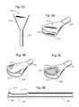
- FIGS. 2A-2Care perspective views of the tip end of three fan-shaped cannulas according to an embodiment of the present invention.
- FIG. 2Dis a top side view of the fan-shaped cannulas whose tips are pictured in FIGS. 2A-2C .
- FIGS. 3A-3Care perspective views of the tip end of three fan-shaped cannulas according to the principles of the present invention.
- FIG. 3Dis a cross section view of the fan-shaped cannula of FIG. 3C .
- FIG. 3Eis a side view of the cannulas of FIGS. 3A-3C .
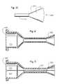
- FIG. 4is a cross section view of a fan-shaped cannula incision sealing device according to the principles of the present invention.
- FIG. 5is a cross section view of a fan-shaped cannula incision sealing device according to the principles of the present invention.
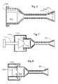
- FIG. 6is a cross section view of a fan-shaped cannula incision sealing device according to the principles of the present invention.
- FIG. 7is a cross section view of a fan-shaped cannula incision sealing device with a plunger according to the principles of the present invention.
- FIG. 8is a cross section view of a fan-shaped cannula incision sealing device with a pneumatic plunger according to the principles of the present invention.
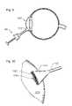
- FIG. 9is a cross section view of a fan-shaped cannula incision sealing device as used in an eye according to the principles of the present invention.
- FIG. 10is a perspective view of a fan-shaped cannula as used on an eye according to the principles of the present invention.
- FIG. 1is a perspective view of a fan-shaped cannula incision sealing device according to the principles of the present invention.
- device 100includes a fan-shaped tip 110 , a cannula 120 , a chamber 130 and a tip opening 140 .
- Chamber 130holds a quantity of a sealant for sealing an incision.
- the term “sealant”includes adhesives, glues, two-part epoxies, and like materials for adhering the edges of an incision or wound.
- Cannula 120carries the sealant to the fan-shaped tip 110 where it is dispensed through the tip opening 140 .
- Fan-shaped tip 110is configured to fit into the incision and properly deliver a quantity of sealant.
- fan-shaped tip 110has an oblong tip opening 140 as shown. This shape allows fan-shaped tip 110 to fill the incision opening. In other words, the shape of fan-shaped tip is such that it generally contacts the entire perimeter of the incision surface. Such a configuration minimizes gapping during use and allows for a more precise delivery of sealant. In such a case, there is little or no gap between fan-shaped tip 110 and the incision.
- Tip opening 140may also be oval or rectangular in shape to facilitate dispensing of the sealant.
- Cannula 120is generally hollow and can be of any configuration. Cannula 120 and fan-shaped tip 110 are typically formed as a single piece. Chamber 130 can be of any suitable configuration and holds a sealant. Fan-shaped tip 110 and cannula 120 are preferably made of a polymer such as polyethylene or polypropylene. In such a case, they can be manufactured using a blow molding technique. In another embodiment of the present invention, chamber 130 is integral with cannula 120 and fan-shaped tip 110 .
- Various liquid sealants dispensed by device 100can be used to seal cataract surgery incisions.
- Typical cataract incisionsinclude clear corneal incisions or sclero-corneal incisions of the tunnel-type or beveled-type. These incisions are typically small—on the order of a few millimeters or less.
- sealantsIn order for sealants to be most efficaciously used, the entire edge of the incision should be rapidly and simultaneously coated with sealant to obtain complete coverage in a single application. It is also desirable to provide some coating inside the incision tunnel as well.
- fan-shaped tip opening 140is oblong and wide enough to cover the entire width of the incision.
- Fan-shaped tip 110is also tapered to minimize gapping during insertion into the incision.
- Fan-shaped tip 110is inserted into an incision or placed on the surface of an incision.
- a sealantis rapidly expelled from fan-shaped tip opening 140 to cover the incision.
- fan-shaped tipis placed inside the incision and the sealant coats the interior of the incision.
- the fan-shaped tipis placed on top of the incision, and the edges of the incision are coated with sealant.
- FIGS. 2A-2Care perspective views of the tip end of three fan-shaped cannulas (straight tip 2 A, curved tip 2 B, spoon tip 2 C) according to an embodiment of the present invention.
- the shape of the cannula tipcan be described with reference to two perpendicular planes that intersect at tip opening 240 .
- the cannula axislies in the first plane such that it bisects tip opening 240 .
- the second planeis perpendicular to the first plane and contains tip opening 240 .
- the straight fan-shaped tipflares-out from the cannula into a fan-shape in the first plane and in the second plane (perpendicular to the first plane) is tapered toward tip opening 240 .
- Tip opening 240can be oval or oblong.
- the edges of the tip opening 240are straight from corner to corner.
- tip opening 240lies in a plane and its top and bottom edges are curved as shown.
- tip opening 240lies in a plane and its top and bottom edges are curved as shown.
- a depressionis located on surface 210 to form a spoon-type shape.
- FIG. 2Ashows a generally oblong or oval shaped tip end.
- Top and bottom surfaces ( 210 , 220 ) of the tipare generally flat.
- the surfaces ( 210 , 220 ) and the tip openingare generally curved.
- the opening of the tipis generally oblong with a curve. This curve can be symmetric as shown (with the curve on the top end of the opening and the bottom end of the opening being generally similar). The curve may also be asymmetric to fit a particular incision geometry.
- top surface 210is generally concave and bottom surface 220 is generally convex.
- the tipis spoon-shaped with the top surface 210 forming a spoon-like depression.
- a lip 230is formed above the tip opening 240 .
- lip 230assists in the proper placement of sealant in or on an incision.
- Lip 230can act as a scraper to remove any excess sealant.
- the edges depicted in FIGS. 2A and 2Bcan also act to scrape away any excess sealant.
- FIG. 2Dis a top side view of the fan-shaped cannulas whose tips are pictured in FIGS. 2A-2C .
- opening 240is located at the top end of the drawing.
- a surface 210 with a fan-shaped profile and tapered tip openingis also depicted.
- the fan-shaped profileextends from cannula 120 to tip opening 240 .
- tip opening 240lies generally in a plane perpendicular to the plane of the paper as shown.
- FIGS. 3A-3Cdepict three fan-shaped cannulas similar to those depicted in FIGS. 2A-2C .
- the fan-shaped cannulas of FIGS. 3A-3Calso include a curved profile along the edge of tip opening 340 .
- This curved profileis depicted in FIG. 3E .
- the tip opening 340lies along a curvilinear surface, such as the curved surface of a cylinder. In this manner, the middle part of the tip opening 340 extends beyond the ends of the tip opening 340 .
- the tip opening 340 of the present inventionmay also be curved inward so that the ends of the tip opening 340 extend beyond the middle of the tip opening 340 .
- Such curved profilesmay be adapted to fit an incision geometry or conform to the generally spherical shape of the eye.
- FIG. 3Adepicts a fan-shaped cannula with a curved tip opening 340 .
- Top and bottom surfaces 310 and 320are generally flat.
- tip opening 340has a curved profile as shown in FIG. 3E .
- the fan-shaped tipextends from cannula 120 to tip opening 340 .
- FIG. 3Bdepicts a fan-shaped cannula with a curved tip opening 340 and curved top and bottom surfaces. Top and bottom surfaces 310 and 320 , respectively, are generally curved. In this manner, the fan-shaped cannula of FIG. 3B is similar to that of FIG. 2B . However, tip opening 340 has a curved profile as shown in FIG. 3E . The fan-shaped tip extends from cannula 120 to tip opening 340 .
- FIG. 3Cdepicts a fan-shaped cannula with a curved tip opening 340 and generally curved top and bottom surfaces that form a spoon shaped cannula tip.
- Top surface 310is generally concave
- bottom surface 320is generally convex so that a lip 330 is formed.
- tip opening 340has a curved profile as shown in FIG. 3E .
- the fan-shaped tipextends from cannula 120 to tip opening 340 .
- FIG. 3Dis a side cross section view of the cannula of FIG. 3C .
- top surface 310has a recess that results in lip 330 at the top end of tip opening 340 .
- Bottom surfacedoes not have such a recess.
- FIG. 4is a cross-section view of a fan-shaped cannula incision sealing device with a straight tip according to the principles of the present invention.
- the embodiment of FIG. 4includes a chamber 410 for holding a quantity of a sealant, fan-shaped cannula 420 for delivering the sealant, and a housing seal 430 .
- Seal 430retains sealant in chamber 410 and provides an air-tight seal.
- a similar sealmay be located at the tip end of fan-shaped cannula 420 .
- Seal 430may be made of any suitable material.
- seal 430is made of a polymer that can be pierced by a syringe or air pulse.
- Chamber 410can be of any suitable configuration and size. Typically, chamber 410 holds enough sealant to properly close an incision. While a straight tip is depicted, any of the previously described tips may be employed.
- FIG. 5is a cross-section view of a fan-shaped cannula incision sealing device with a straight tip according to the principles of the present invention.
- the embodiment of FIG. 5includes a dual chamber arrangement. First chamber 510 and second chamber 520 are separated by divider 550 . Otherwise, fan-shaped cannula 530 and seal 540 are similar to their like components of FIG. 4 .
- the dual chamber arrangementallows for the use of a two part sealant or epoxy. Such a sealant is mixed together when applied to an incision. The mixing of the two part sealant causes a chemical reaction that results in a bonding effect.
- First chamber 510 and second chamber 520may be of any suitable shape and size. While depicted as being the same size, one of the chambers may be bigger than the other.
- Divider 550is typically a polymer sheet that is inserted or molded into the device. Likewise, a similar seal 560 may be located at the tip end of fan-shaped cannula 540 . While a straight tip is depicted, any of the previously described tips may be employed.
- FIG. 6is a cross-section view of a fan-shaped cannula incision sealing device with a straight tip according to the principles of the present invention.
- the length of fan-shaped cannula 620 and the width of its tip endcan be adjusted.
- Fan-shaped cannula 620can be snapped or cut along score marks 630 or 640 to be adjusted.
- a single cannula designcan be adjusted by the end user to fit various incision configurations. For example, a larger incision may not require any adjustment.
- a smaller incisionmay require the end user to snap or cut fan-shaped cannula 620 along score marks 630 . This results in a shorter fan-shaped cannula 620 with a smaller opening at its tip end. While a straight tip is depicted, any of the previously described tips may be employed.
- the cross section shape of the fan-shaped cannula 620may differ along its length so that snapping or cutting it at score marks 630 or 640 results in different shaped openings at its tip end. For example, it may be desirable to have a different shaped opening for a larger incision than for a smaller incision. In such a case, the tip end of fan-shaped cannula 620 may be oblong. When cut or snapped at score marks 630 , the opening of the tip end of fan-shaped cannula 620 may be oval. Other shapes or configurations of the opening of tip end are also possible.
- Chamber 610 and seal 650are like their similar components in FIG. 4 . While depicted as score marks, any other type of cutting guide may be used. For example, a depression or marked line may be used as score marks.
- the device of FIG. 6can be used to apply a sealant to an ophthalmic incision.
- a medical professionalremoves a portion of a fan-shaped cannula along a set of score marks, such as score marks 630 or 640 .
- the device of FIG. 6is then attached to a plunger.
- the plungeris located such that it can expel the sealant from the chamber 610 .
- the end of the fan-shaped cannula 620is inserted into the incision and the plunger is activated to expel the sealant so that the sealant contacts an edge of the incision. Excess sealant is removed by applying an edge of the fan-shaped cannula 620 to the incision. This edge acts as a scraper to remove excess sealant.
- FIG. 7is a cross-section view of a fan-shaped cannula incision sealing device with a plunger according to the principles of the present invention.
- a syringehas been attached to the device of FIG. 4 .
- the resulting deviceis ready for use to inject a sealant into an ophthalmic incision.
- the deviceincludes chamber 710 , fan-shaped cannula 720 , plunger 730 , plunger housing 740 , and seal 750 (which has been pierced by plunger 730 ).
- a standard syringemay be used.
- the fan-shaped cannula incision sealing deviceis attached to one end of the syringe.
- the plunger(or other structure such as the mounting hub of the syringe) pierces seal 750 .
- Plunger 730can then be depressed to push the sealant out of chamber 710 , through fan-shaped cannula 720 , and into (or onto) an incision.
- Plunger 730 and plunger housing 740may be of any suitable configuration and may be implemented with a standard syringe of any suitable size. Likewise, a similar seal may be located at the tip end of fan-shaped cannula.
- FIG. 8is a cross-section view of a fan-shaped cannula incision sealing device with a pneumatic plunger according to the principles of the present invention.
- a pneumatic driverhas been attached to the device of FIG. 4 .
- the resulting deviceis ready for use to inject a sealant into an ophthalmic incision.
- the deviceincludes chamber 810 , fan-shaped cannula 820 , plunger 830 , and seal 840 (which has been pierced by plunger 830 ).
- sealantmay be pneumatically expelled from chamber 810 , through cannula 820 , and into (or onto) an incision. Force from a pneumatic pulse drives plunger 830 downward.
- a similar sealmay be located at the tip end of fan-shaped cannula.
- FIG. 9is a cross section view of a fan-shaped cannula wound sealing device as used in an eye according to the principles of the present invention.
- fan-shaped cannula incision sealing device with a syringe 900is being used to close an incision made during cataract surgery.
- An incisionhas been made in cornea 920 .
- the end 910 of fan-shaped cannulahas been inserted into this incision so that a sealant can be applied to seal the incision.
- a cataract incisionis depicted, any other type of incision made during ophthalmic procedures can be sealed in a like manner.
- a scleral incisionmay be sealed using a fan-shaped cannula incision sealing device.
- FIG. 10is a perspective view of a fan-shaped cannula as used on an eye according to the principles of the present invention.
- a fan shaped cannulais configured to apply a sealant to an incision in an eye 1005 .
- Sealant 1030may be applied to the surface of eye 1005 at the incision site, or it may be applied to the incision itself.
- the fan-shaped tipextends along surface 1010 from cannula 120 to tip opening 1020 . Sealant 1030 exits tip opening 1020 and is applied to the incision.
- a fan-shaped tip with a curved profilelike that depicted in FIG. 2B or 2 C) is used. The curvature of the fan-shaped tip (curvature of surface 1010 and the surface opposite surface 1010 ) helps the fan-shaped tip to conform to the generally spherical surface of the eye 1005 .
- the present inventionprovides an improved system for sealing incisions made during ophthalmic procedures.
- the present inventionprovides a fan-shaped cannula incision sealing device that dispenses an adhesive, epoxy, glue, sealant, or the like to close an incision.
- the tip end of the fan-shaped cannula and its openingare configured to properly dispense the sealant based on the incision geometry.
Landscapes
- Health & Medical Sciences (AREA)
- Life Sciences & Earth Sciences (AREA)
- General Health & Medical Sciences (AREA)
- Public Health (AREA)
- Heart & Thoracic Surgery (AREA)
- Surgery (AREA)
- Engineering & Computer Science (AREA)
- Animal Behavior & Ethology (AREA)
- Veterinary Medicine (AREA)
- Biomedical Technology (AREA)
- Ophthalmology & Optometry (AREA)
- Nuclear Medicine, Radiotherapy & Molecular Imaging (AREA)
- Vascular Medicine (AREA)
- Medical Informatics (AREA)
- Molecular Biology (AREA)
- Prostheses (AREA)
Abstract
Description
Claims (18)
Priority Applications (1)
| Application Number | Priority Date | Filing Date | Title |
|---|---|---|---|
| US11/939,005US8790366B2 (en) | 2007-11-13 | 2007-11-13 | Fan-shaped cannula for sealing ophthalmic incisions |
Applications Claiming Priority (1)
| Application Number | Priority Date | Filing Date | Title |
|---|---|---|---|
| US11/939,005US8790366B2 (en) | 2007-11-13 | 2007-11-13 | Fan-shaped cannula for sealing ophthalmic incisions |
Publications (2)
| Publication Number | Publication Date |
|---|---|
| US20090125057A1 US20090125057A1 (en) | 2009-05-14 |
| US8790366B2true US8790366B2 (en) | 2014-07-29 |
Family
ID=40624482
Family Applications (1)
| Application Number | Title | Priority Date | Filing Date |
|---|---|---|---|
| US11/939,005Active2032-09-03US8790366B2 (en) | 2007-11-13 | 2007-11-13 | Fan-shaped cannula for sealing ophthalmic incisions |
Country Status (1)
| Country | Link |
|---|---|
| US (1) | US8790366B2 (en) |
Cited By (3)
| Publication number | Priority date | Publication date | Assignee | Title |
|---|---|---|---|---|
| US20140142663A1 (en)* | 2012-11-20 | 2014-05-22 | Biolase, Inc. | Eyelid Treatment Device |
| US11559294B2 (en) | 2018-07-19 | 2023-01-24 | Sanulus Medical, LLC | Devices and methods for targeted delivery of a substance |
| US11896523B2 (en) | 2018-07-19 | 2024-02-13 | Sanulus Medical, LLC | Devices and methods for targeted delivery of a substance |
Families Citing this family (4)
| Publication number | Priority date | Publication date | Assignee | Title |
|---|---|---|---|---|
| JP5788383B2 (en)* | 2009-05-19 | 2015-09-30 | コヘラ メディカル インコーポレイテッド | Device for delivering adhesive |
| US8343106B2 (en) | 2009-12-23 | 2013-01-01 | Alcon Research, Ltd. | Ophthalmic valved trocar vent |
| JP5990103B2 (en) | 2009-12-23 | 2016-09-07 | アルコン リサーチ, リミテッド | Ophthalmic valved trocar cannula |
| US8864703B2 (en) | 2010-10-05 | 2014-10-21 | Alcon Research, Ltd. | Drug introduction and placement system |
Citations (46)
| Publication number | Priority date | Publication date | Assignee | Title |
|---|---|---|---|---|
| US1557620A (en)* | 1923-08-17 | 1925-10-20 | Robinson Henry | Eyecup |
| US2330695A (en)* | 1942-06-18 | 1943-09-28 | Eric W Eweson | Eye washing device |
| US2623663A (en)* | 1951-02-14 | 1952-12-30 | George J Elsasser | Suction cup dispensing spout |
| US2919696A (en)* | 1958-04-04 | 1960-01-05 | Rinaldy August | Instrument for applying contact lenses |
| US3250436A (en)* | 1963-12-31 | 1966-05-10 | Albert J Kurtz | Pouring spout assembly for a dispensing container |
| US3342318A (en)* | 1965-10-05 | 1967-09-19 | Continental Can Co | Tablet dispenser |
| US3524537A (en)* | 1968-09-25 | 1970-08-18 | American Cyanamid Co | Package containing 2-cyanoacrylic ester adhesives |
| US3653380A (en)* | 1970-02-16 | 1972-04-04 | American Cyanamid Co | Aerosol powder dosage dispensing device |
| US3964643A (en)* | 1973-12-27 | 1976-06-22 | L'oreal | Unpressurized container for holding a plurality of products separately and dispensing them simultaneously |
| US3998226A (en)* | 1975-09-22 | 1976-12-21 | Edward G. Gomez | Inhalation device for encapsulated concentrates |
| US4138040A (en)* | 1976-04-12 | 1979-02-06 | Pacer Industries, Inc. | Dispenser for anaerobic and cyanoacrylate adhesives |
| US4530356A (en) | 1983-02-08 | 1985-07-23 | Helfgott Maxwell A | Ophthalmic surgical instrument with beveled tip |
| US4595434A (en)* | 1983-09-15 | 1986-06-17 | American Can Company | Collapsible dispensing tube with an orifice sealed with multi-layer sealant sheet material |
| US4941872A (en)* | 1985-01-22 | 1990-07-17 | C. R. Bard, Inc. | Control handle for surgical irrigation and suction device |
| US5046493A (en)* | 1988-02-16 | 1991-09-10 | James Kropkowski | Nasal dispenser |
| US5106221A (en)* | 1990-06-26 | 1992-04-21 | Plastiques Rg & Gael Diot | Device for packaging and applying a product contained in a flexible, leaktight tube |
| US5112339A (en) | 1990-06-18 | 1992-05-12 | Ophthalmocare, Inc. | Apparatus for extracting cataractous tissue |
| US5215221A (en)* | 1992-05-07 | 1993-06-01 | The Procter & Gamble Company | Disposable unit dose dispenser for powdered medicants |
| US5254084A (en)* | 1993-03-26 | 1993-10-19 | Geary Gregory L | Peritoneal catheter device for dialysis |
| US5292332A (en)* | 1992-07-27 | 1994-03-08 | Lee Benjamin I | Methods and device for percutanceous sealing of arterial puncture sites |
| US5336170A (en)* | 1992-07-29 | 1994-08-09 | Research Medical, Inc. | Surgical site visualization wand |
| US5407441A (en) | 1992-06-04 | 1995-04-18 | Greenbaum; Scott | Ophthalmologic cannula |
| US5409125A (en)* | 1989-12-11 | 1995-04-25 | Aktiebolaget Astra | Unit dose container |
| US5571246A (en)* | 1995-02-16 | 1996-11-05 | Alldredge; Andrew L. | Collapsible metered dose inhaler |
| US5649943A (en) | 1994-06-15 | 1997-07-22 | Amoils; Percy | Ophthalmic treatment apparatus and its use |
| US5665106A (en)* | 1993-09-28 | 1997-09-09 | Hemodynamics, Inc. | Vascular patch applicator |
| US5730336A (en)* | 1996-01-02 | 1998-03-24 | Cascade Designs, Inc. | Dispensing valve for a flexible liquid container |
| US5730748A (en)* | 1995-05-19 | 1998-03-24 | General Surgical Innovations, Inc. | Methods and devices for blood vessel harvesting |
| US5735833A (en)* | 1996-12-11 | 1998-04-07 | Bristol-Myers Squibb Co. | Lavage tip |
| US5752964A (en) | 1996-04-16 | 1998-05-19 | Mericle; Robert W. | Surgical knot pusher with flattened spatulated tip |
| US5928611A (en)* | 1995-06-07 | 1999-07-27 | Closure Medical Corporation | Impregnated applicator tip |
| US6027471A (en)* | 1995-01-18 | 2000-02-22 | Fallon; Timothy J. | Apparatus for applying a hemostatic agent onto a tissue |
| US6085742A (en)* | 1997-04-02 | 2000-07-11 | Aeromax Technologies, Inc. | Intrapulmonary delivery device |
| US6135984A (en) | 1999-01-06 | 2000-10-24 | Dishler; Jon G. | Cannula for use in corrective laser eye surgery |
| US6398277B1 (en)* | 2001-03-15 | 2002-06-04 | Mcdonald Marguerite B. | Contact lens insertion device |
| US6413245B1 (en) | 1999-10-21 | 2002-07-02 | Alcon Universal Ltd. | Sub-tenon drug delivery |
| US6425704B2 (en)* | 2000-01-07 | 2002-07-30 | Closure Medical Corporation | Adhesive applicators with improved applicator tips |
| US6530374B1 (en)* | 1998-07-24 | 2003-03-11 | Fausto Ferraro | Air filter device provided with gripping means in the form of a mouthpiece |
| US20030047184A1 (en)* | 2001-01-12 | 2003-03-13 | Lockhart Artis R. | Medicament respiratory delivery device |
| US6585689B1 (en)* | 1997-12-08 | 2003-07-01 | Cardeon Corporation | Aortic catheter and methods for inducing cardioplegic arrest and for selective aortic perfusion |
| US6722364B2 (en)* | 2001-01-12 | 2004-04-20 | Becton, Dickinson And Company | Medicament inhalation delivery devices and methods for using the same |
| US6764463B1 (en)* | 2000-06-27 | 2004-07-20 | Barry Farris | Method and needleless apparatus for the storage of a first substance followed by subsequent mixing with a second substance and transfer without ambient air incursion |
| US6782887B2 (en)* | 2001-01-12 | 2004-08-31 | Becton, Dickinson And Company | Medicament respiratory delivery device and cartridge |
| US6845772B2 (en)* | 1999-12-01 | 2005-01-25 | Innovata Biomed Limited | Inhaler |
| US7141048B1 (en) | 2002-10-17 | 2006-11-28 | Alcon, Inc. | Vitreoretinal instrument |
| US7285107B1 (en) | 2002-10-17 | 2007-10-23 | Alcon, Inc. | Vitreoretinal instrument |
- 2007
- 2007-11-13USUS11/939,005patent/US8790366B2/enactiveActive
Patent Citations (49)
| Publication number | Priority date | Publication date | Assignee | Title |
|---|---|---|---|---|
| US1557620A (en)* | 1923-08-17 | 1925-10-20 | Robinson Henry | Eyecup |
| US2330695A (en)* | 1942-06-18 | 1943-09-28 | Eric W Eweson | Eye washing device |
| US2623663A (en)* | 1951-02-14 | 1952-12-30 | George J Elsasser | Suction cup dispensing spout |
| US2919696A (en)* | 1958-04-04 | 1960-01-05 | Rinaldy August | Instrument for applying contact lenses |
| US3250436A (en)* | 1963-12-31 | 1966-05-10 | Albert J Kurtz | Pouring spout assembly for a dispensing container |
| US3342318A (en)* | 1965-10-05 | 1967-09-19 | Continental Can Co | Tablet dispenser |
| US3524537A (en)* | 1968-09-25 | 1970-08-18 | American Cyanamid Co | Package containing 2-cyanoacrylic ester adhesives |
| US3653380A (en)* | 1970-02-16 | 1972-04-04 | American Cyanamid Co | Aerosol powder dosage dispensing device |
| US3964643A (en)* | 1973-12-27 | 1976-06-22 | L'oreal | Unpressurized container for holding a plurality of products separately and dispensing them simultaneously |
| US3998226A (en)* | 1975-09-22 | 1976-12-21 | Edward G. Gomez | Inhalation device for encapsulated concentrates |
| US4138040A (en)* | 1976-04-12 | 1979-02-06 | Pacer Industries, Inc. | Dispenser for anaerobic and cyanoacrylate adhesives |
| US4530356A (en) | 1983-02-08 | 1985-07-23 | Helfgott Maxwell A | Ophthalmic surgical instrument with beveled tip |
| US4595434A (en)* | 1983-09-15 | 1986-06-17 | American Can Company | Collapsible dispensing tube with an orifice sealed with multi-layer sealant sheet material |
| US4941872A (en)* | 1985-01-22 | 1990-07-17 | C. R. Bard, Inc. | Control handle for surgical irrigation and suction device |
| US5046493A (en)* | 1988-02-16 | 1991-09-10 | James Kropkowski | Nasal dispenser |
| US5409125A (en)* | 1989-12-11 | 1995-04-25 | Aktiebolaget Astra | Unit dose container |
| US5112339A (en) | 1990-06-18 | 1992-05-12 | Ophthalmocare, Inc. | Apparatus for extracting cataractous tissue |
| US5106221A (en)* | 1990-06-26 | 1992-04-21 | Plastiques Rg & Gael Diot | Device for packaging and applying a product contained in a flexible, leaktight tube |
| US5215221A (en)* | 1992-05-07 | 1993-06-01 | The Procter & Gamble Company | Disposable unit dose dispenser for powdered medicants |
| US5407441A (en) | 1992-06-04 | 1995-04-18 | Greenbaum; Scott | Ophthalmologic cannula |
| US5292332A (en)* | 1992-07-27 | 1994-03-08 | Lee Benjamin I | Methods and device for percutanceous sealing of arterial puncture sites |
| US5336170A (en)* | 1992-07-29 | 1994-08-09 | Research Medical, Inc. | Surgical site visualization wand |
| US5254084A (en)* | 1993-03-26 | 1993-10-19 | Geary Gregory L | Peritoneal catheter device for dialysis |
| US5665106A (en)* | 1993-09-28 | 1997-09-09 | Hemodynamics, Inc. | Vascular patch applicator |
| US5649943A (en) | 1994-06-15 | 1997-07-22 | Amoils; Percy | Ophthalmic treatment apparatus and its use |
| US6027471A (en)* | 1995-01-18 | 2000-02-22 | Fallon; Timothy J. | Apparatus for applying a hemostatic agent onto a tissue |
| US5571246A (en)* | 1995-02-16 | 1996-11-05 | Alldredge; Andrew L. | Collapsible metered dose inhaler |
| US5730748A (en)* | 1995-05-19 | 1998-03-24 | General Surgical Innovations, Inc. | Methods and devices for blood vessel harvesting |
| US5928611A (en)* | 1995-06-07 | 1999-07-27 | Closure Medical Corporation | Impregnated applicator tip |
| US5730336A (en)* | 1996-01-02 | 1998-03-24 | Cascade Designs, Inc. | Dispensing valve for a flexible liquid container |
| US5752964A (en) | 1996-04-16 | 1998-05-19 | Mericle; Robert W. | Surgical knot pusher with flattened spatulated tip |
| US5735833A (en)* | 1996-12-11 | 1998-04-07 | Bristol-Myers Squibb Co. | Lavage tip |
| US6085742A (en)* | 1997-04-02 | 2000-07-11 | Aeromax Technologies, Inc. | Intrapulmonary delivery device |
| US6585689B1 (en)* | 1997-12-08 | 2003-07-01 | Cardeon Corporation | Aortic catheter and methods for inducing cardioplegic arrest and for selective aortic perfusion |
| US6530374B1 (en)* | 1998-07-24 | 2003-03-11 | Fausto Ferraro | Air filter device provided with gripping means in the form of a mouthpiece |
| US6135984A (en) | 1999-01-06 | 2000-10-24 | Dishler; Jon G. | Cannula for use in corrective laser eye surgery |
| US6413245B1 (en) | 1999-10-21 | 2002-07-02 | Alcon Universal Ltd. | Sub-tenon drug delivery |
| US6845772B2 (en)* | 1999-12-01 | 2005-01-25 | Innovata Biomed Limited | Inhaler |
| US6425704B2 (en)* | 2000-01-07 | 2002-07-30 | Closure Medical Corporation | Adhesive applicators with improved applicator tips |
| US6764463B1 (en)* | 2000-06-27 | 2004-07-20 | Barry Farris | Method and needleless apparatus for the storage of a first substance followed by subsequent mixing with a second substance and transfer without ambient air incursion |
| US20030047184A1 (en)* | 2001-01-12 | 2003-03-13 | Lockhart Artis R. | Medicament respiratory delivery device |
| US6722364B2 (en)* | 2001-01-12 | 2004-04-20 | Becton, Dickinson And Company | Medicament inhalation delivery devices and methods for using the same |
| US6782887B2 (en)* | 2001-01-12 | 2004-08-31 | Becton, Dickinson And Company | Medicament respiratory delivery device and cartridge |
| US7040316B2 (en)* | 2001-01-12 | 2006-05-09 | Becton, Dickinson And Company | Medicament inhalation delivery devices and methods for using the same |
| US7270127B2 (en)* | 2001-01-12 | 2007-09-18 | Becton, Dickinson And Company | Medicament respiratory delivery device |
| US7540285B2 (en)* | 2001-01-12 | 2009-06-02 | Becton, Dickinson And Company | Medicament inhalation delivery devices and methods for using the same |
| US6398277B1 (en)* | 2001-03-15 | 2002-06-04 | Mcdonald Marguerite B. | Contact lens insertion device |
| US7141048B1 (en) | 2002-10-17 | 2006-11-28 | Alcon, Inc. | Vitreoretinal instrument |
| US7285107B1 (en) | 2002-10-17 | 2007-10-23 | Alcon, Inc. | Vitreoretinal instrument |
Non-Patent Citations (1)
| Title |
|---|
| Katena Products, Inc., Katena Eye Instruments Catalog, downloaded on Nov. 17, 2006, 1 page, http://www.katena.com/html/product-detail.cfm. |
Cited By (6)
| Publication number | Priority date | Publication date | Assignee | Title |
|---|---|---|---|---|
| US20140142663A1 (en)* | 2012-11-20 | 2014-05-22 | Biolase, Inc. | Eyelid Treatment Device |
| US10039932B2 (en)* | 2012-11-20 | 2018-08-07 | Biolase, Inc. | Eyelid treatment device |
| US11559294B2 (en) | 2018-07-19 | 2023-01-24 | Sanulus Medical, LLC | Devices and methods for targeted delivery of a substance |
| US11896523B2 (en) | 2018-07-19 | 2024-02-13 | Sanulus Medical, LLC | Devices and methods for targeted delivery of a substance |
| US12089893B2 (en) | 2018-07-19 | 2024-09-17 | Sanulus Medical, LLC | Devices and methods for targeted delivery of a substance |
| US12414761B2 (en) | 2018-07-19 | 2025-09-16 | Sanulus Medical, LLC | Devices and methods for targeted delivery of a substance |
Also Published As
| Publication number | Publication date |
|---|---|
| US20090125057A1 (en) | 2009-05-14 |
Similar Documents
| Publication | Publication Date | Title |
|---|---|---|
| US8790366B2 (en) | Fan-shaped cannula for sealing ophthalmic incisions | |
| US5547473A (en) | Pneumatic vitrectomy for retinal attachment | |
| AU2009335954B2 (en) | Gilled phacoemulsification irrigation sleeve | |
| US7175594B2 (en) | Ophthalmic sulcus speculum | |
| US5984889A (en) | Apparatus and method for delivering viscoelastic material to an eye | |
| CA2586203C (en) | Irrigation/aspiration tip | |
| US5676679A (en) | Apparatus for implanting an artifical meshwork in glaucoma surgery | |
| US7141048B1 (en) | Vitreoretinal instrument | |
| EP2209448B1 (en) | Probe tip and infusion sleeve for use with ophthalmological surgery | |
| JP5886199B2 (en) | Treatment instruments and accessories | |
| US7285107B1 (en) | Vitreoretinal instrument | |
| EP1302185A1 (en) | Simultaneous surgical injection and aspiration with pedal control | |
| WO1995031141A1 (en) | Pneumatic vitrectomy for retinal attachment | |
| EP1632205A1 (en) | Surgical apparatus | |
| US20220008250A1 (en) | Devices and methods for targeted delivery of material | |
| EP1759675B1 (en) | Nozzle for a surgical irrigating handpiece | |
| EP1767173A1 (en) | Surgical apparatus | |
| Kazaykin | My Approach to Retinal Detachment: A Russian Perspective | |
| Kazaykin | My Approach to Retinal | |
| Chang et al. | Improving surgical safety with modern phaco technology | |
| HK1146800B (en) | Probe tip and infusion sleeve for use with ophthalmological surgery |
Legal Events
| Date | Code | Title | Description |
|---|---|---|---|
| AS | Assignment | Owner name:ALCON MANUFACTURING, LTD., TEXAS Free format text:ASSIGNMENT OF ASSIGNORS INTEREST;ASSIGNOR:CORDOVA, DIANA M.;REEL/FRAME:020102/0636 Effective date:20071113 | |
| AS | Assignment | Owner name:ALCON RESEARCH, LTD., TEXAS Free format text:MERGER;ASSIGNOR:ALCON MANUFACTURING, LTD.;REEL/FRAME:021266/0729 Effective date:20080101 Owner name:ALCON RESEARCH, LTD.,TEXAS Free format text:MERGER;ASSIGNOR:ALCON MANUFACTURING, LTD.;REEL/FRAME:021266/0729 Effective date:20080101 | |
| STCF | Information on status: patent grant | Free format text:PATENTED CASE | |
| MAFP | Maintenance fee payment | Free format text:PAYMENT OF MAINTENANCE FEE, 4TH YEAR, LARGE ENTITY (ORIGINAL EVENT CODE: M1551) Year of fee payment:4 | |
| AS | Assignment | Owner name:ALCON INC., SWITZERLAND Free format text:CONFIRMATORY DEED OF ASSIGNMENT EFFECTIVE APRIL 8, 2019;ASSIGNOR:NOVARTIS AG;REEL/FRAME:051454/0788 Effective date:20191111 | |
| AS | Assignment | Owner name:ALCON RESEARCH, LLC, TEXAS Free format text:MERGER;ASSIGNOR:ALCON RESEARCH, LTD.;REEL/FRAME:053273/0022 Effective date:20190228 | |
| AS | Assignment | Owner name:ALCON INC., SWITZERLAND Free format text:CONFIRMATORY DEED OF ASSIGNMENT EFFECTIVE APRIL 8, 2019;ASSIGNOR:ALCON RESEARCH, LLC;REEL/FRAME:053293/0484 Effective date:20200619 | |
| MAFP | Maintenance fee payment | Free format text:PAYMENT OF MAINTENANCE FEE, 8TH YEAR, LARGE ENTITY (ORIGINAL EVENT CODE: M1552); ENTITY STATUS OF PATENT OWNER: LARGE ENTITY Year of fee payment:8 |