US8790363B2 - Three dimensional, low friction vasoocclusive coil, and method of manufacture - Google Patents
Three dimensional, low friction vasoocclusive coil, and method of manufactureDownload PDFInfo
- Publication number
- US8790363B2 US8790363B2US11/436,200US43620006AUS8790363B2US 8790363 B2US8790363 B2US 8790363B2US 43620006 AUS43620006 AUS 43620006AUS 8790363 B2US8790363 B2US 8790363B2
- Authority
- US
- United States
- Prior art keywords
- vasoocclusive
- vasculature
- configuration
- dimensional
- coil
- Prior art date
- Legal status (The legal status is an assumption and is not a legal conclusion. Google has not performed a legal analysis and makes no representation as to the accuracy of the status listed.)
- Expired - Fee Related, expires
Links
Images


Classifications
- A—HUMAN NECESSITIES
- A61—MEDICAL OR VETERINARY SCIENCE; HYGIENE
- A61B—DIAGNOSIS; SURGERY; IDENTIFICATION
- A61B17/00—Surgical instruments, devices or methods
- A61B17/12—Surgical instruments, devices or methods for ligaturing or otherwise compressing tubular parts of the body, e.g. blood vessels or umbilical cord
- A61B17/12022—Occluding by internal devices, e.g. balloons or releasable wires
- A61B17/12099—Occluding by internal devices, e.g. balloons or releasable wires characterised by the location of the occluder
- A61B17/12109—Occluding by internal devices, e.g. balloons or releasable wires characterised by the location of the occluder in a blood vessel
- A61B17/12113—Occluding by internal devices, e.g. balloons or releasable wires characterised by the location of the occluder in a blood vessel within an aneurysm
- A—HUMAN NECESSITIES
- A61—MEDICAL OR VETERINARY SCIENCE; HYGIENE
- A61B—DIAGNOSIS; SURGERY; IDENTIFICATION
- A61B17/00—Surgical instruments, devices or methods
- A61B17/12—Surgical instruments, devices or methods for ligaturing or otherwise compressing tubular parts of the body, e.g. blood vessels or umbilical cord
- A61B17/12022—Occluding by internal devices, e.g. balloons or releasable wires
- A61B17/12131—Occluding by internal devices, e.g. balloons or releasable wires characterised by the type of occluding device
- A61B17/1214—Coils or wires
- A61B17/12145—Coils or wires having a pre-set deployed three-dimensional shape
- A—HUMAN NECESSITIES
- A61—MEDICAL OR VETERINARY SCIENCE; HYGIENE
- A61B—DIAGNOSIS; SURGERY; IDENTIFICATION
- A61B17/00—Surgical instruments, devices or methods
- A61B17/12—Surgical instruments, devices or methods for ligaturing or otherwise compressing tubular parts of the body, e.g. blood vessels or umbilical cord
- A61B17/12022—Occluding by internal devices, e.g. balloons or releasable wires
- A61B2017/1205—Introduction devices
- A61B2017/12054—Details concerning the detachment of the occluding device from the introduction device
- A61B2017/12068—Details concerning the detachment of the occluding device from the introduction device detachable by heat
- A61B2017/12072—Details concerning the detachment of the occluding device from the introduction device detachable by heat the heat created by laser light
- A—HUMAN NECESSITIES
- A61—MEDICAL OR VETERINARY SCIENCE; HYGIENE
- A61B—DIAGNOSIS; SURGERY; IDENTIFICATION
- A61B17/00—Surgical instruments, devices or methods
- A61B17/12—Surgical instruments, devices or methods for ligaturing or otherwise compressing tubular parts of the body, e.g. blood vessels or umbilical cord
- A61B17/12022—Occluding by internal devices, e.g. balloons or releasable wires
- A61B2017/1205—Introduction devices
- A61B2017/12054—Details concerning the detachment of the occluding device from the introduction device
- A61B2017/12068—Details concerning the detachment of the occluding device from the introduction device detachable by heat
- A61B2017/12077—Joint changing shape upon application of heat, e.g. bi-metal or reversible thermal memory
Definitions
- This inventionrelates generally to vasoocclusive devices, and more particularly concerns a vasoocclusive device that has a first elongated, reduced friction configuration in which the vasoocclusive device may be deployed through a catheter or cannula to an anatomical cavity at a site in the vasculature to be treated, and that has a three dimensional second configuration assumed by the vasoocclusive device at the site to be treated for filling the anatomical cavity.
- One specific field of interventional therapy that has been able to advantageously use recent developments in technologyis the treatment of neurovascular defects. More specifically, as smaller and more capable structures and materials have been developed, treatment of vascular defects in the human brain which were previously untreatable or represented unacceptable risks via conventional surgery have become amenable to treatment.
- One type of non-surgical therapy that has become advantageous for the treatment of defects in the neurovasculaturehas been the placement by way of a catheter of vasoocclusive devices in a damaged portion of a vein or artery.
- Vasoocclusion devicesare therapeutic devices that are placed within the vasculature of the human body, typically via a catheter, either to block the flow of blood through a vessel making up that portion of the vasculature through the formation of an embolus or to form such an embolus within an aneurysm stemming from the vessel.
- the vasoocclusive devicescan take a variety of configurations, and are generally formed of one or more elements that are larger in the deployed configuration than when they are within the delivery catheter prior to placement.
- One widely used vasoocclusive deviceis a helical wire coil having a deployed configuration which may be dimensioned to engage the walls of the vessels.
- vasoocclusive devicescan be accomplished by a variety of means, including via a catheter in which the device is pushed through the catheter by a pusher to deploy the device.
- the vasoocclusive deviceswhich can have a primary shape of a coil of wire that is then formed into a more complex secondary shape, can be produced in such a way that they will pass through the lumen of a catheter in a linear shape and take on a complex shape as originally formed after being deployed into the area of interest, such as an aneurysm.
- a variety of detachment mechanisms to release the device from a pusherhave been developed and are known in the art.
- micro-coils formed of very small diameter wireare used in order to restrict, reinforce, or to occlude such small diameter areas of the vasculature.
- materialshave been suggested for use in such micro-coils, including nickel-titanium alloys, copper, stainless steel, platinum, tungsten, various plastics or the like, each of which offers certain benefits in various applications.
- Nickel-titanium alloysare particularly advantageous for the fabrication of such micro coils, in that they can have super-elastic or shape memory properties, and thus can be manufactured to easily fit into a linear portion of a catheter, but attain their originally formed, more complex shape when deployed.
- vasoocclusive coilfor example, that has a three dimensional in-filling coil configuration, formed by winding a wire into a helix, and then winding the helix into a secondary form which forms a generally spherical shape, by winding the primary coil about poles placed on winding mandrel.
- the secondary wound coilis then annealed on the winding mandrel, and the coil is then removed from the winding mandrel and loaded into a carrier for introduction into a delivery catheter.
- Another similar type of vasoocclusive deviceis known that can be formed from one or more strands, and can be wound to form a generally spherical or ovoid shape when released and relaxed at the site to be treated.
- Another implantable vasoocclusive device having multiple secondary layers of primary windingshas a final shape that is a generally spherical coil formed of linear or helical primary coils that are wound into a secondary form having three layers. The inner winding is wound and then the second layer formed by winding in the opposite direction of the first layer. The final configuration is a chunky or stepped shape approximately a sphere, ovoid, or egg.
- Yet another conventional implant for vessel occlusionis made from helical elements of metal or synthetic material by twisting or coiling the elements and forming them into a secondary shape such as a rosette or double rosette for implantation using a catheter, and another vasoocclusive device is known that has a final conical shape.
- vasoocclusive devicethat has a three dimensional final form that can be used to fill an anatomical cavity at a site in the vasculature to be treated, reduces friction between the coil and the catheter through which it is delivered to the site to be treated, and ultimately helps to prevent coil misalignment.
- the present inventionmeets these and other needs.
- the present inventionprovides for an improved vasoocclusive coil, that has a three dimensional box or cube-shaped portion, and a method of making the coil.
- the three dimensional portionwill form a basket for filling the anatomical cavity at the site in the vasculature to be treated.
- the three dimensional portion of the vasoocclusive coilcomprises at least one strand of a flexible material formed to have an a first inoperable, substantially linear configuration for insertion into and through a catheter or cannula to a desired portion of the vasculature to be treated, and a second operable, three dimensional box or cube-shaped configuration for occluding the desired portion of the vasculature to be treated.
- This substantially linear configurationallows for reduction of friction of the coil within a catheter or cannula being used to deliver the vasoocclusive coil to the site in the vasculature to be treated, and ultimately helps prevent coil realignment or misalignment.
- the ultimate coil volume that otherwise might be limited due to frictional constraints of three dimensional coilswill not be compromised with the device of the present invention.
- the vasoocclusive coilmay optionally also include a portion having a first inoperable, substantially linear configuration for insertion into and through a catheter or cannula to a desired portion of the vasculature to be treated, and a second operable configuration that is substantially J-shaped or helically shaped, for filling and reinforcing the three dimensional box or cube-shaped basket portion, for occluding the desired portion of the vasculature to be treated, in order to combine the best qualities of a three dimensional coil and a J-shaped or helical coil.
- the present inventionaccordingly provides for a vasoocclusive device that is adapted to be inserted into a portion of a vasculature for occluding the portion of the vasculature for use in interventional therapy and vascular surgery.
- the vasoocclusive devicecomprises at least one strand of a flexible material formed to have a first inoperable, substantially linear configuration for insertion into and through a catheter or cannula to a desired portion of the vasculature to be treated, and a second operable, three dimensional configuration for occluding the desired portion of the vasculature to be treated.
- the vasoocclusive deviceadvantageously has a portion having a second operable, three dimensional box or cube shape for filling the anatomical cavity at the site in the vasculature to be treated, and may optionally include a portion having a second operable, substantially J-shape or helical shape for filling and reinforcing the distal, three dimensional box or cube shaped portion when it is implanted at the site in the vasculature to be treated.
- the present inventionalso provides for a method of making the vasoocclusive device.
- the methodgenerally comprises the steps of winding at least one strand of a flexible shape memory material about a mandrel formed of a refractory material in a three dimensional configuration of the vasoocclusive coil to form a distal portion of the vasoocclusive coil; heating the at least one strand of a flexible shape memory material wound about the mandrel for a sufficient period of time to impart the form to the shape memory material included in the device to form an operable, three dimensional configuration of the vasoocclusive coil; removing the vasoocclusive coil from the mandrel; and cold working the vasoocclusive coil into a desired elongated configuration for placement into a catheter or cannula for use.
- the mandrel about which the at least one flexible strand forming the vasoocclusive coil is woundhas a substantially orthogonal or cubical body with a plurality of posts disposed on the body.
- six postsare disposed on the body aligned with the three orthogonal x, y and z axes through the body of the mandrel, for aligning and shaping the box or cube shaped portion of the vasoocclusive device as it is wound on the mandrel.
- one of the postsis provided with a handle that can optionally also be used as a mandrel for winding a portion of the vasoocclusive coil with a helical shape.
- the step of heatingcomprises heating the at least one strand of a flexible shape memory material wound about the mandrel at a temperature of about 1100° F. for at least about 4 hours to impart the form to the shape memory material included in the device to form an operable, three dimensional configuration of the distal portion of the vasoocclusive coil.
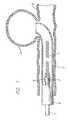
- FIG. 1is a cross section of a vascular member with an aneurysm illustrating the approach of a vasoocclusive coil towards the aneurysm.
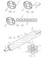
- FIG. 2is a side elevational view showing a first embodiment of a second operable, three dimensional configuration of the vasoocclusive coil of the invention.
- FIG. 3Ais a side elevational view showing a first option of the first embodiment of FIG. 2 , including a two-dimensional substantially J-shaped portion.
- FIG. 3Bis a side elevational view showing a second option of the first embodiment of FIG. 2 , including a helically shaped portion.
- FIG. 4is a perspective view of a radiopaque microstrand cable used in forming the vasoocclusive coil according to the invention.
- FIG. 5is a cross-section at 5 - 5 of FIG. 4 .
- FIG. 6is an alternate preferred embodiment of the invention including a plurality of radiopaque strands within the cable.
- FIG. 7is an alternate preferred embodiment of the present invention wherein strands of the cable are arranged within an exterior binding consisting of multiple straps about the cable.
- FIG. 8is a perspective view of the embodiment of FIG. 7 .
- FIG. 9is an alternative embodiment to the embodiment of FIG. 8 wherein the external binding of the cable represents a sheath wound about the cable.
- FIGS. 10 a and 10 bare perspectives of alternative embodiments of the embodiment of FIG. 9 .
- FIG. 11is a cross-section of an alternative embodiment in which a plurality of multi-strand cables are included within an external sheath surrounding the cable.
- FIG. 12is a perspective view of the embodiment of FIG. 11 .
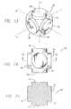
- FIG. 13is a perspective view of a first embodiment of a mandrel used for making the vasoocclusive coil according to the method of the invention.
- FIG. 14is a plan view of the mandrel of FIG. 13 .
- FIG. 15is a sectional view of the mandrel of FIG. 13 taken along line 15 - 15 of FIG. 14 .
- FIG. 16is a perspective view of a second embodiment of a mandrel used for making the vasoocclusive coil according to the method of the invention.
- FIG. 17is a plan view of the mandrel of FIG. 16 .
- FIG. 18is a sectional view of the mandrel of FIG. 16 taken along line 18 - 18 of FIG. 17 .
- the inventionis accordingly embodied in a vasoocclusive device that is adapted to be inserted into a portion of a vasculature for occluding the portion of the vasculature for use in interventional therapy and vascular surgery.
- the vasoocclusive coil 1is formed from at least one strand of a flexible material formed to have a first inoperable, substantially linear configuration, as illustrated in FIG. 1 , for insertion through a micro-catheter 2 into a desired portion of the vasculature to be treated, such as an aneurysm, or other anatomical malformation of the vasculature to be treated, and a second operable, three dimensional configuration illustrated in FIGS. 2 , 3 A and 3 B, for occluding the desired portion of the vasculature to be treated.
- FIG. 1illustrates a helically wound vasoocclusive coil 1 which is formed to fit within the micro-catheter for insertion into an area upon which a therapeutic procedure is to be performed.
- FIG. 1further shows a catheter pusher member 3 for delivering a vasoocclusive coil 1 for insertion into an aneurysm 4 projecting laterally from a blood vessel 5 .
- the end of the micro-catheter 2is typically introduced into the opening of the aneurism by use of a guide wire (note shown), and the coil and pusher member are introduced into the micro-catheter to insert the vasoocclusive coil into the aneurysm.
- catheter pusher member to which the vasoocclusive coil is mountedis an optical fiber pusher which is attached to the coil by a collar 6 of shape memory material such as a nickel titanium super-elastic alloy, or a shape memory polymer, for example.
- shape memory materialsuch as a nickel titanium super-elastic alloy, or a shape memory polymer, for example.
- the vasoocclusive coilis typically introduced into the aneurysm and is then pushed from the micro-catheter until the vasoocclusive coil fills the cavity.
- the shape memory collar 6is heated to a temperature which allows it to be shrunk onto the vasoocclusive coil.
- the collarcan be attached to optical fiber pusher by an adhesive which retains high strength at temperatures beyond the shape memory material transition point.
- light energy from a source of coherent lightis introduced into the proximal end of the optical fiber (not shown) and propagated in the distal end 7 of the fiber to cause the shape memory material collar to return to its previous shape and release the vasoocclusive coil.
- the vasoocclusive devicepreferably has a portion 8 having a second operable, three dimensional shape for filling the anatomical cavity at the site in the vasculature to be treated.
- the three dimensional portion of the vasoocclusive deviceis orthogonal, having a box or cube shape for filling the anatomical cavity at the site in the vasculature to be treated.
- the vasooclusive devicemay also include a portion 9 having a second operable, substantially J-shaped coil shape, for filling and reinforcing the distal, three dimensional shaped portion 8 when the vasoocclusive device is implanted at the site in the vasculature to be treated.
- the vasooclusive devicemay also include a portion 9 ′ having a second operable, substantially helical coil shape, for filling and reinforcing the distal, three dimensional shaped portion 8 when the vasoocclusive device is implanted at the site in the vasculature to be treated.
- the vasoocclusive coilsare formed from a multi-stranded micro-cable, although the vasoocclusive coils can also be made from a single strand of a flexible material formed to have an a first inoperable, substantially linear configuration for insertion into and through a catheter or cannula to a desired portion of the vasculature to be treated, and a second operable, three dimensional configuration for occluding the desired portion of the vasculature to be treated.
- the multi-stranded micro-cablemay be formed from a wide variety of materials, including stainless steels if some sacrifice of radiopacity may be tolerated.
- Very desirable materials of constructionare materials which maintain their shape despite being subjected to high stress.
- Certain “super-elastic alloys”include nickel/titanium alloys (48-58 atomic % nickel, and optionally containing modest amounts of iron); copper/zinc alloys (38-42 weight % zinc); copper/zinc alloys containing 1-10 weight % of beryllium, silicon, tin, aluminum, or gallium; or nickel/aluminum alloys (36-38 atomic % aluminum).
- nickel/titanium alloys48-58 atomic % nickel, and optionally containing modest amounts of iron
- copper/zinc alloys38-42 weight % zinc
- copper/zinc alloys containing 1-10 weight % of beryllium, silicon, tin, aluminum, or galliumor nickel/aluminum alloys (36-38 atomic % aluminum).
- Particularly preferredare the alloys described in U.S. Pat. Nos. 3,174,851; 3,351,463; and
- the strandmay be constructed of a polymer, such as polyvinyl alcohol foam, for example.
- the wireshould be of sufficient diameter to provide a hoop strength to the resulting device sufficient to hold the device in place within the chosen body cavity without distending the wall of the cavity and without moving from the cavity as a result of the repetitive fluid pulsing found in the vascular system. Should a super-elastic alloy such as nitinol be used, the diameter of the coil wire can be significantly smaller than that used when the relatively ductile platinum or platinum/tungsten alloy is used as the material of construction.
- the vasoocclusive coilsare preferably formed from a multi-stranded micro-cable 10 that is typically approximately from 0.0021 to 0.0045 inches in diameter, and comprises a plurality of flexible strands 12 of nickel-titanium alloy, with at least one centrally, axially disposed radiopaque wire 14 which is approximately from 0.0007 to 0.0015 inches in diameter. While the above stated diameters represent those presently known to be compatible with the invention, larger or smaller diameters may be useful for particular applications.
- the central radiopaque wire 14can be formed of platinum or gold, for example, other similar suitable radiopaque metals, or other suitable types of radiopaque materials, in order to provide a radiopaque marker of the deployed configuration of a device made of the cable during vascular surgery.
- the radiopaque materialmay be a metal or a polymer.
- Suitable metals and alloys for the wiringinclude platinum group metals, especially platinum rhodium, palladium, as well as tungsten, gold, silver, tantalum, and alloys of these metals. Highly preferred is a platinum/tungsten alloy.
- a vasoocclusive device made from the micro-cablebecomes virtually kink resistant compared to the single strand wires now commonly used in micro-coils.
- the multi-strand cable construction of the inventionallows the micro-wires of the cable to slip across each other and reinforce each other rather than break or take a set. Also, by incorporating a stranded radiopaque material such as platinum, tungsten or gold into the cable construction, the device is radiopaque in sizes much smaller than with other constructions.
- FIG. 5is a cross-section of the micro-cable of FIG. 4 at 5 - 5 illustrating one presently preferred arrangement of the strands within the cable.
- the exterior strands 12are formed of a resilient material chosen to provide the characteristics desired for a specific application in interventional therapies.
- this materialis a nickel titanium super-elastic alloy which is heat treated such that the alloy is highly flexible at a temperature appropriate for introduction into the body via a catheter or cannula.
- such a cablecan have a central core 14 of a radiopaque material such as gold or platinum, thus dramatically enhancing the radiopacity of the cable.
- a solid super-elastic wire of the same diameter as the cablewould have substantially less radiopacity than the cable of the invention with the central gold or platinum wire and the construction of the invention provides numerous other highly desirable characteristics. Among these characteristics is the relative flexibility and resistance to kinking of the cable compared to an equivalent single wire and substantially greater accommodation of the cable to bending, etc., with resultant lessening of trauma to the surrounding tissue and ease of placement in a small body cavity.
- FIG. 6is an example of one such construction 40 in which radiopacity is more desirable than in other forms and for that reason a number of radiopaque strands 42 , in this illustration four in number, are formed into the cable along with three resilient material strands 44 . It will also be appreciated that a larger or smaller number of strands may be incorporated into a given cable and the cables may be formed of multiple cables in order to provide desired bending and strength characteristics. It will also be appreciated by those skilled in the art that the invention is adaptable to the use of a variety of materials which by themselves would not have been easily adaptable to micro devices for interventional therapies.
- composite cables incorporating one or more strands of a desired materialcan be configured with other strands providing strength, flexibility, shape memory, super-elasticity, radiopacity or the like for previously unavailable characteristics in micro devices.
- FIG. 7illustrates a cross-section of an additional presently preferred embodiment of the invention in which the strands 12 , 14 of the micro-cable 10 are bundled and banded at intervals by bands 50 to produce a composite banded cable 52 in order to provide increased flexibility without unraveling or dislocation of the strands in the cable.
- FIG. 8is a perspective view of the banded cable 50 of this embodiment. While the illustrated configuration shows the strands being laid parallel within the cable, it is also possible in this construction to include both twisted cables as the primary cables 10 within the outer bands 50 to form the composite cable 52 . This configuration can use one or more longitudinal strands 14 which are radiopaque, thus providing a continuous indication of radiopacity within the cable. As a further alternative embodiment, it is possible for the longitudinal cable 52 to be formed of a single inner cable 10 with bands 50 .
- FIG. 9illustrates a further embodiment of the invention in which longitudinal strands of cables are contained within a wound cover 56 for the purposes of providing a composite guide wire or the like 58 having improved torqueability.
- a constructionhas particular advantages for guidewire designs having improved radiopacity in very small diameters. It will be appreciated that in this configuration, as well as the other longitudinally arranged multi-stranded cables, the number of strands and the degree to which they extend along the cable within the sheath is a variable which can be used to provide increased stiffness, pushability and torqueability in some sections with greater flexibility in others.
- composite cables according to the inventioncan incorporate additional elements normally not available in solid guide wires, such as optical, thermal or ultrasound imaging elements, therapeutic agent delivery catheters, and can take advantage of materials which are not readily adaptable to prior art catheter or guide wire designs incorporating a primary wire structured element.
- FIGS. 10 a and 10 billustrate a further variable available because of the invention; the exterior wrapped cover 56 can be wound at greater or lesser intervals 60 along the outside to provide variations in the torqueability and stiffness of the composite cable.
- the thickness and width of the wrapping cover 56as well as its material composition along the composite guide wire 58 , can offer further capabilities for customizing the design for various applications.
- FIGS. 11 and 12illustrate a cross-section of a micro-cable according to the invention which has at least one overall exterior sheath to contain the micro-cable.
- the micro-cablemay be made of one or more multiple strand elements which may further include twisted or longitudinal strands within their construction.
- the sheathmay also be used to control the torqueability characteristics of the cable, and the sheath may be multi-layered with different materials in order to provide a graduated bending and stiffness characteristic over the length of the cable.
- a three dimensional occlusive deviceadapted to be inserted into a portion of a vasculature for occluding the portion of the vasculature for use in interventional therapy and vascular surgery, can be formed as described above, from at least one multi-stranded micro-cable having a plurality of flexible strands of a resilient material, with at least one radiopaque strand to provide a radiopaque marker for the device during vascular surgery.
- the occlusive deviceis configured to have a first inoperable, substantially linear, elongated configuration for insertion into and through a catheter or cannula to a desired portion of the vasculature to be treated, and a second operable, three dimensional configuration for occluding the desired portion of the vasculature to be treated.
- a mandrelis used for annealing the coils in the desired second operable, substantially orthogonal three dimensional box or cube shape.
- a mandrel suitable for making such second operable, three dimensional shaped occlusive devicescan be formed of a refractory material, such as alumina or zirconia, for example.
- the mandrelforms a support for the winding and heat treatment of the micro-cable, plurality of micro-cables, or composite micro-cable occlusive device as described above, and ideally will not contaminate the occlusive device during heat treatment of the device.
- one or more of the flexible strands forming the vasoocclusive coilare wound around the surface of a mandrel 70 having a substantially orthogonal main body 72 with six cylindrical posts 74 having a diameter slightly smaller than that of the main body, disposed on the body and aligned with the three orthogonal x, y and z axes through the body of the mandrel, for aligning and shaping the distal portion of the vasoocclusive device as it is wound on the mandrel.
- the mandrelmay optionally also include an aperture, such as a threaded aperture 78 , provided in a face 80 of one of the posts 74 and coaxially aligned with the orthogonal axis the post, for receiving a corresponding end 82 of a generally cylindrical handle 84 .
- the end 82 of the handlemay also be correspondingly threaded.
- the handlecan optionally be used as a mandrel for winding a portion of the vasoocclusive coil with a helical shape.
- the surface of the mandrelmay also have one or more apertures for receiving one or more ends of the strands, to assist winding into the desired form.
- the wound occlusive deviceis preferably heat treated at a suitable temperature and a sufficient period of time to impart the form to the shape memory material included in the device. While heat treatment at a temperature of about 1100° F. for approximately 4 hours or more is typically sufficient to impart the form to the occlusive device when the shape memory material is a nickel titanium super-elastic alloy, although the temperature utilized can be substantially lowered, and the duration of heat treatment adjusted accordingly, as will be appreciated by those skilled in the art.
- the occlusive deviceAfter the heat treatment, the occlusive device is removed from the mandrel, and cold worked into the desired collapsed elongated configuration for placement into a catheter or cannula for use. When the occlusive device reaches its destination in the vasculature during vascular therapy, it assumes the primary shape imparted from the heat treatment on the mandrel.
Landscapes
- Health & Medical Sciences (AREA)
- Surgery (AREA)
- Life Sciences & Earth Sciences (AREA)
- Heart & Thoracic Surgery (AREA)
- Molecular Biology (AREA)
- Vascular Medicine (AREA)
- Engineering & Computer Science (AREA)
- Biomedical Technology (AREA)
- Reproductive Health (AREA)
- Medical Informatics (AREA)
- Nuclear Medicine, Radiotherapy & Molecular Imaging (AREA)
- Animal Behavior & Ethology (AREA)
- General Health & Medical Sciences (AREA)
- Public Health (AREA)
- Veterinary Medicine (AREA)
- Neurosurgery (AREA)
- Surgical Instruments (AREA)
Abstract
Description
Claims (8)
Priority Applications (1)
| Application Number | Priority Date | Filing Date | Title |
|---|---|---|---|
| US11/436,200US8790363B2 (en) | 1995-04-20 | 2006-05-17 | Three dimensional, low friction vasoocclusive coil, and method of manufacture |
Applications Claiming Priority (7)
| Application Number | Priority Date | Filing Date | Title |
|---|---|---|---|
| US08/425,106US5645558A (en) | 1995-04-20 | 1995-04-20 | Anatomically shaped vasoocclusive device and method of making the same |
| US08/799,439US5766219A (en) | 1995-04-20 | 1997-02-13 | Anatomically shaped vasoocclusive device and method for deploying same |
| US09/089,328US6090125A (en) | 1995-04-20 | 1998-06-02 | Anatomically shaped vasoocclusive device and method of making the same |
| US09/140,495US6171326B1 (en) | 1998-08-27 | 1998-08-27 | Three dimensional, low friction vasoocclusive coil, and method of manufacture |
| US09/590,794US6638291B1 (en) | 1995-04-20 | 2000-06-08 | Three dimensional, low friction vasoocclusive coil, and method of manufacture |
| US10/664,001US7316701B2 (en) | 1995-04-20 | 2003-09-16 | Three dimensional, low friction vasoocclusive coil, and method of manufacture |
| US11/436,200US8790363B2 (en) | 1995-04-20 | 2006-05-17 | Three dimensional, low friction vasoocclusive coil, and method of manufacture |
Related Parent Applications (3)
| Application Number | Title | Priority Date | Filing Date |
|---|---|---|---|
| US09/089,328Continuation-In-PartUS6090125A (en) | 1995-04-20 | 1998-06-02 | Anatomically shaped vasoocclusive device and method of making the same |
| US09/140,495Continuation-In-PartUS6171326B1 (en) | 1995-04-20 | 1998-08-27 | Three dimensional, low friction vasoocclusive coil, and method of manufacture |
| US10/664,001ContinuationUS7316701B2 (en) | 1995-04-20 | 2003-09-16 | Three dimensional, low friction vasoocclusive coil, and method of manufacture |
Publications (2)
| Publication Number | Publication Date |
|---|---|
| US20060241686A1 US20060241686A1 (en) | 2006-10-26 |
| US8790363B2true US8790363B2 (en) | 2014-07-29 |
Family
ID=37188019
Family Applications (1)
| Application Number | Title | Priority Date | Filing Date |
|---|---|---|---|
| US11/436,200Expired - Fee RelatedUS8790363B2 (en) | 1995-04-20 | 2006-05-17 | Three dimensional, low friction vasoocclusive coil, and method of manufacture |
Country Status (1)
| Country | Link |
|---|---|
| US (1) | US8790363B2 (en) |
Cited By (4)
| Publication number | Priority date | Publication date | Assignee | Title |
|---|---|---|---|---|
| US9307998B2 (en) | 1997-07-10 | 2016-04-12 | Stryker Corporation | Methods and devices for the treatment of aneurysms |
| US9314326B2 (en) | 2002-04-12 | 2016-04-19 | Stryker Corporation | System and method for retaining vaso-occlusive devices within an aneurysm |
| US11389173B2 (en) | 2020-11-19 | 2022-07-19 | Rapid Medical Ltd. | Systems and methods for facilitating endovascular coil delivery |
| US12121460B2 (en) | 2010-05-27 | 2024-10-22 | Idev Technologies, Inc. | Stent delivery system with pusher assembly |
Families Citing this family (28)
| Publication number | Priority date | Publication date | Assignee | Title |
|---|---|---|---|---|
| US7018401B1 (en) | 1999-02-01 | 2006-03-28 | Board Of Regents, The University Of Texas System | Woven intravascular devices and methods for making the same and apparatus for delivery of the same |
| MX2009004291A (en) | 2006-10-22 | 2009-09-07 | Idev Technologies Inc | Methods for securing strand ends and the resulting devices. |
| KR101659197B1 (en) | 2006-10-22 | 2016-09-22 | 이데브 테크놀로지스, 아이엔씨. | Devices and methods for stent advancement |
| WO2009076515A1 (en)* | 2007-12-11 | 2009-06-18 | Cornell University | Method and apparatus for sealing an opening in the side wall of a body lumen |
| EP2633823B1 (en) | 2008-04-21 | 2016-06-01 | Covidien LP | Braid-ball embolic devices and delivery systems |
| WO2009140437A1 (en) | 2008-05-13 | 2009-11-19 | Nfocus Neuromedical, Inc. | Braid implant delivery systems |
| JP5750051B2 (en)* | 2009-01-22 | 2015-07-15 | コーネル ユニヴァーシティー | Method and apparatus for restricting flow through a lumen wall |
| EP2413840B1 (en) | 2009-04-02 | 2016-08-17 | Endoshape, Inc. | Vascular occlusion devices |
| CA2812012C (en) | 2010-09-10 | 2018-01-02 | Medina Medical, Inc. | Devices and methods for the treatment of vascular defects |
| US8998947B2 (en) | 2010-09-10 | 2015-04-07 | Medina Medical, Inc. | Devices and methods for the treatment of vascular defects |
| WO2012135859A2 (en) | 2011-04-01 | 2012-10-04 | Cornell University | Method and apparatus for restricting flow through an opening in the side wall of a body lumen, and/or for reinforcing a weakness in the side wall of a body lumen, while still maintaining substantially normal flow through the body lumen |
| EP2763601B1 (en) | 2011-10-07 | 2020-03-25 | Cornell University | Apparatus for restricting flow through an opening in a body lumen while maintaining normal flow |
| US10603043B2 (en) | 2012-01-17 | 2020-03-31 | Endoshape, Inc. | Occlusion device for a vascular or biological lumen |
| US10327781B2 (en) | 2012-11-13 | 2019-06-25 | Covidien Lp | Occlusive devices |
| CN105073031B (en) | 2013-03-13 | 2017-10-27 | 内形有限公司 | Continuous embolic coil and its carrying method and device |
| US10531979B2 (en)* | 2013-03-15 | 2020-01-14 | Fabian Hermann Urban Füglister | Tongue deformation implant |
| CN108186074A (en)* | 2014-02-27 | 2018-06-22 | 因库麦迪斯有限公司 | For treating the framework microcoils of vascular diseases |
| US9375333B1 (en) | 2015-03-06 | 2016-06-28 | Covidien Lp | Implantable device detachment systems and associated devices and methods |
| US11051822B2 (en)* | 2016-06-28 | 2021-07-06 | Covidien Lp | Implant detachment with thermal activation |
| US10478195B2 (en) | 2016-08-04 | 2019-11-19 | Covidien Lp | Devices, systems, and methods for the treatment of vascular defects |
| US10576099B2 (en) | 2016-10-21 | 2020-03-03 | Covidien Lp | Injectable scaffold for treatment of intracranial aneurysms and related technology |
| US10675036B2 (en) | 2017-08-22 | 2020-06-09 | Covidien Lp | Devices, systems, and methods for the treatment of vascular defects |
| US10905432B2 (en)* | 2018-08-22 | 2021-02-02 | Covidien Lp | Aneurysm treatment coils and associated systems and methods of use |
| US10912569B2 (en) | 2018-08-22 | 2021-02-09 | Covidien Lp | Aneurysm treatment coils and associated systems and methods of use |
| US11730485B2 (en) | 2018-12-17 | 2023-08-22 | Covidien Lp | Devices, systems, and methods for the treatment of vascular defects |
| JP7751566B2 (en)* | 2019-09-13 | 2025-10-08 | アバンテック バスキュラー コーポレイション | Intravascular coil and method for making same |
| WO2021092618A1 (en) | 2019-11-04 | 2021-05-14 | Covidien Lp | Devices, systems, and methods for treatment of intracranial aneurysms |
| US11931041B2 (en) | 2020-05-12 | 2024-03-19 | Covidien Lp | Devices, systems, and methods for the treatment of vascular defects |
Citations (132)
| Publication number | Priority date | Publication date | Assignee | Title |
|---|---|---|---|---|
| US1341052A (en) | 1916-06-15 | 1920-05-25 | Francis G Gale | Chain |
| FR592182A (en) | 1924-03-24 | 1925-07-28 | Urethral probe | |
| US1667730A (en) | 1928-05-01 | of chicago | ||
| US2078182A (en) | 1935-08-09 | 1937-04-20 | Sirian Wire And Contact Compan | Tungsten manufacture |
| US2549335A (en) | 1947-04-18 | 1951-04-17 | Rahthus Max | Ornamental chain |
| US3334629A (en) | 1964-11-09 | 1967-08-08 | Bertram D Cohn | Occlusive device for inferior vena cava |
| US3649224A (en) | 1968-04-18 | 1972-03-14 | Sylvania Electric Prod | Method of making nonsag filaments for electric lamps |
| US3868956A (en) | 1972-06-05 | 1975-03-04 | Ralph J Alfidi | Vessel implantable appliance and method of implanting it |
| US4205680A (en) | 1978-01-13 | 1980-06-03 | Work Wear Corporation, Inc. | Radiopaque laparatomy sponge |
| GB2066839A (en) | 1979-12-29 | 1981-07-15 | Vysoka Skola Chem Tech | A Method of Manufacture of Perfumed Detergents |
| DE3203410A1 (en) | 1981-05-08 | 1982-11-25 | VEB Kombinat Wälzlager und Normteile, DDR 9022 Karl-Marx-Stadt | Closure body and method for its production |
| US4448624A (en) | 1983-03-11 | 1984-05-15 | Lockheed Corporation | Method and apparatus for making filament wound cylindrical structres |
| US4494531A (en) | 1982-12-06 | 1985-01-22 | Cook, Incorporated | Expandable blood clot filter |
| US4512338A (en) | 1983-01-25 | 1985-04-23 | Balko Alexander B | Process for restoring patency to body vessels |
| US4531933A (en) | 1982-12-07 | 1985-07-30 | C. R. Bard, Inc. | Helical ureteral stent |
| US4553545A (en) | 1981-09-16 | 1985-11-19 | Medinvent S.A. | Device for application in blood vessels or other difficultly accessible locations and its use |
| EP0183372A1 (en) | 1984-10-19 | 1986-06-04 | RAYCHEM CORPORATION (a Delaware corporation) | Prosthetic stent |
| US4638803A (en) | 1982-09-30 | 1987-01-27 | Rand Robert W | Medical apparatus for inducing scar tissue formation in a body |
| US4655771A (en) | 1982-04-30 | 1987-04-07 | Shepherd Patents S.A. | Prosthesis comprising an expansible or contractile tubular body |
| US4718907A (en) | 1985-06-20 | 1988-01-12 | Atrium Medical Corporation | Vascular prosthesis having fluorinated coating with varying F/C ratio |
| US4748986A (en) | 1985-11-26 | 1988-06-07 | Advanced Cardiovascular Systems, Inc. | Floppy guide wire with opaque tip |
| US4768507A (en) | 1986-02-24 | 1988-09-06 | Medinnovations, Inc. | Intravascular stent and percutaneous insertion catheter system for the dilation of an arterial stenosis and the prevention of arterial restenosis |
| US4795458A (en) | 1987-07-02 | 1989-01-03 | Regan Barrie F | Stent for use following balloon angioplasty |
| US4800882A (en) | 1987-03-13 | 1989-01-31 | Cook Incorporated | Endovascular stent and delivery system |
| US4813925A (en) | 1987-04-21 | 1989-03-21 | Medical Engineering Corporation | Spiral ureteral stent |
| US4820298A (en) | 1987-11-20 | 1989-04-11 | Leveen Eric G | Internal vascular prosthesis |
| US4830003A (en) | 1988-06-17 | 1989-05-16 | Wolff Rodney G | Compressive stent and delivery system |
| US4832055A (en) | 1988-07-08 | 1989-05-23 | Palestrant Aubrey M | Mechanically locking blood clot filter |
| US4850960A (en) | 1987-07-08 | 1989-07-25 | Joseph Grayzel | Diagonally tapered, bevelled tip introducing catheter and sheath and method for insertion |
| US4856516A (en) | 1989-01-09 | 1989-08-15 | Cordis Corporation | Endovascular stent apparatus and method |
| US4907336A (en) | 1987-03-13 | 1990-03-13 | Cook Incorporated | Method of making an endovascular stent and delivery system |
| US4922924A (en) | 1989-04-27 | 1990-05-08 | C. R. Bard, Inc. | Catheter guidewire with varying radiopacity |
| EP0382014A1 (en) | 1989-01-26 | 1990-08-16 | Advanced Cardiovascular Systems, Inc. | Intravascular endoprothesis |
| US4957501A (en) | 1987-12-31 | 1990-09-18 | Biomat, S.A.R.L. | Anti-embolic filter |
| US4957479A (en) | 1988-10-17 | 1990-09-18 | Vance Products Incorporated | Indwelling ureteral stent placement apparatus |
| US4990155A (en) | 1989-05-19 | 1991-02-05 | Wilkoff Howard M | Surgical stent method and apparatus |
| US4994069A (en) | 1988-11-02 | 1991-02-19 | Target Therapeutics | Vaso-occlusion coil and method |
| US5015253A (en) | 1989-06-15 | 1991-05-14 | Cordis Corporation | Non-woven endoprosthesis |
| US5019090A (en) | 1988-09-01 | 1991-05-28 | Corvita Corporation | Radially expandable endoprosthesis and the like |
| US5026377A (en) | 1989-07-13 | 1991-06-25 | American Medical Systems, Inc. | Stent placement instrument and method |
| US5025799A (en) | 1987-05-13 | 1991-06-25 | Wilson Bruce C | Steerable memory alloy guide wires |
| DE4102550A1 (en) | 1990-02-02 | 1991-08-08 | Stephan Prof Dr Bockenheimer | Sealing blood vessel fistula - involves inserted sleeve with spiral support with turns bridged by impervious elastic material |
| US5041084A (en) | 1990-08-09 | 1991-08-20 | Dlp, Inc. | Single stage venous catheter |
| US5064435A (en) | 1990-06-28 | 1991-11-12 | Schneider (Usa) Inc. | Self-expanding prosthesis having stable axial length |
| US5071407A (en) | 1990-04-12 | 1991-12-10 | Schneider (U.S.A.) Inc. | Radially expandable fixation member |
| US5104404A (en) | 1989-10-02 | 1992-04-14 | Medtronic, Inc. | Articulated stent |
| US5108407A (en) | 1990-06-08 | 1992-04-28 | Rush-Presbyterian St. Luke's Medical Center | Method and apparatus for placement of an embolic coil |
| US5122136A (en) | 1990-03-13 | 1992-06-16 | The Regents Of The University Of California | Endovascular electrolytically detachable guidewire tip for the electroformation of thrombus in arteries, veins, aneurysms, vascular malformations and arteriovenous fistulas |
| DE9205797U1 (en) | 1992-04-30 | 1992-06-17 | Brohm-Schmitz-Rode, Andrea, Dr.med., 5100 Aachen | Self-expanding mesh basket for the closure of human hollow organs |
| US5133732A (en) | 1987-10-19 | 1992-07-28 | Medtronic, Inc. | Intravascular stent |
| US5133731A (en) | 1990-11-09 | 1992-07-28 | Catheter Research, Inc. | Embolus supply system and method |
| US5141502A (en) | 1991-08-28 | 1992-08-25 | Macaluso Jr Joseph N | Ureteral stent |
| US5147370A (en) | 1991-06-12 | 1992-09-15 | Mcnamara Thomas O | Nitinol stent for hollow body conduits |
| US5151105A (en) | 1991-10-07 | 1992-09-29 | Kwan Gett Clifford | Collapsible vessel sleeve implant |
| US5160341A (en) | 1990-11-08 | 1992-11-03 | Advanced Surgical Intervention, Inc. | Resorbable urethral stent and apparatus for its insertion |
| EP0518704A1 (en) | 1991-06-14 | 1992-12-16 | Scimed Life Systems, Inc. | Temporary stents and method of manufacture |
| US5176625A (en) | 1990-10-25 | 1993-01-05 | Brisson A Glen | Stent for ureter |
| US5176661A (en) | 1988-09-06 | 1993-01-05 | Advanced Cardiovascular Systems, Inc. | Composite vascular catheter |
| US5183085A (en) | 1991-09-27 | 1993-02-02 | Hans Timmermans | Method and apparatus for compressing a stent prior to insertion |
| US5186992A (en) | 1990-03-12 | 1993-02-16 | The Bentley-Harris Manufacturing Company | Braided product and method of making same |
| US5203772A (en) | 1989-01-09 | 1993-04-20 | Pilot Cardiovascular Systems, Inc. | Steerable medical device |
| US5213275A (en) | 1991-07-17 | 1993-05-25 | General Dynamics Corporation, Space Systems Division | Reeding edge for securing in place fiber band during filament winding operation |
| US5217484A (en) | 1991-06-07 | 1993-06-08 | Marks Michael P | Retractable-wire catheter device and method |
| US5221269A (en) | 1990-10-15 | 1993-06-22 | Cook Incorporated | Guide for localizing a nonpalpable breast lesion |
| US5222969A (en) | 1992-03-16 | 1993-06-29 | Rolando Gillis | Intravascular stent for cardiovascular intervention |
| US5226911A (en) | 1991-10-02 | 1993-07-13 | Target Therapeutics | Vasoocclusion coil with attached fibrous element(s) |
| US5228453A (en) | 1991-05-07 | 1993-07-20 | Target Therapeutics, Inc. | Catheter guide wire |
| US5234456A (en) | 1990-02-08 | 1993-08-10 | Pfizer Hospital Products Group, Inc. | Hydrophilic stent |
| US5238004A (en) | 1990-04-10 | 1993-08-24 | Boston Scientific Corporation | High elongation linear elastic guidewire |
| US5250071A (en) | 1992-09-22 | 1993-10-05 | Target Therapeutics, Inc. | Detachable embolic coil assembly using interlocking clasps and method of use |
| US5251640A (en) | 1992-03-31 | 1993-10-12 | Cook, Incorporated | Composite wire guide shaft |
| US5256146A (en) | 1991-10-11 | 1993-10-26 | W. D. Ensminger | Vascular catheterization system with catheter anchoring feature |
| US5261916A (en) | 1991-12-12 | 1993-11-16 | Target Therapeutics | Detachable pusher-vasoocclusive coil assembly with interlocking ball and keyway coupling |
| US5304194A (en) | 1991-10-02 | 1994-04-19 | Target Therapeutics | Vasoocclusion coil with attached fibrous element(s) |
| US5304195A (en) | 1991-12-12 | 1994-04-19 | Target Therapeutics, Inc. | Detachable pusher-vasoocclusive coil assembly with interlocking coupling |
| US5312415A (en) | 1992-09-22 | 1994-05-17 | Target Therapeutics, Inc. | Assembly for placement of embolic coils using frictional placement |
| US5314472A (en) | 1991-10-01 | 1994-05-24 | Cook Incorporated | Vascular stent |
| US5334210A (en) | 1993-04-09 | 1994-08-02 | Cook Incorporated | Vascular occlusion assembly |
| US5336205A (en) | 1993-02-25 | 1994-08-09 | Target Therapeutics, Inc. | Flow directed catheter |
| US5342387A (en) | 1992-06-18 | 1994-08-30 | American Biomed, Inc. | Artificial support for a blood vessel |
| US5350398A (en) | 1991-05-13 | 1994-09-27 | Dusan Pavcnik | Self-expanding filter for percutaneous insertion |
| US5350397A (en) | 1992-11-13 | 1994-09-27 | Target Therapeutics, Inc. | Axially detachable embolic coil assembly |
| US5354295A (en) | 1990-03-13 | 1994-10-11 | Target Therapeutics, Inc. | In an endovascular electrolytically detachable wire and tip for the formation of thrombus in arteries, veins, aneurysms, vascular malformations and arteriovenous fistulas |
| US5370683A (en) | 1992-03-25 | 1994-12-06 | Cook Incorporated | Vascular stent |
| US5382259A (en) | 1992-10-26 | 1995-01-17 | Target Therapeutics, Inc. | Vasoocclusion coil with attached tubular woven or braided fibrous covering |
| US5383887A (en) | 1992-12-28 | 1995-01-24 | Celsa Lg | Device for selectively forming a temporary blood filter |
| US5395390A (en) | 1992-05-01 | 1995-03-07 | The Beth Israel Hospital Association | Metal wire stent |
| US5405377A (en) | 1992-02-21 | 1995-04-11 | Endotech Ltd. | Intraluminal stent |
| US5423849A (en) | 1993-01-15 | 1995-06-13 | Target Therapeutics, Inc. | Vasoocclusion device containing radiopaque fibers |
| US5423829A (en) | 1993-11-03 | 1995-06-13 | Target Therapeutics, Inc. | Electrolytically severable joint for endovascular embolic devices |
| US5441516A (en) | 1994-03-03 | 1995-08-15 | Scimed Lifesystems Inc. | Temporary stent |
| US5443478A (en) | 1992-09-02 | 1995-08-22 | Board Of Regents, The University Of Texas System | Multi-element intravascular occlusion device |
| US5454795A (en) | 1994-06-27 | 1995-10-03 | Target Therapeutics, Inc. | Kink-free spiral-wound catheter |
| US5514176A (en) | 1995-01-20 | 1996-05-07 | Vance Products Inc. | Pull apart coil stent |
| US5522836A (en) | 1994-06-27 | 1996-06-04 | Target Therapeutics, Inc. | Electrolytically severable coil assembly with movable detachment point |
| US5527354A (en) | 1991-06-28 | 1996-06-18 | Cook Incorporated | Stent formed of half-round wire |
| US5527338A (en) | 1992-09-02 | 1996-06-18 | Board Of Regents, The University Of Texas System | Intravascular device |
| US5536274A (en) | 1991-02-15 | 1996-07-16 | pfm Produkterfur Die Medizin | Spiral implant for organ pathways |
| US5549624A (en) | 1994-06-24 | 1996-08-27 | Target Therapeutics, Inc. | Fibered vasooclusion coils |
| US5562698A (en) | 1994-03-09 | 1996-10-08 | Cook Incorporated | Intravascular treatment system |
| US5562641A (en) | 1993-05-28 | 1996-10-08 | A Bromberg & Co. Ltd. | Two way shape memory alloy medical stent |
| US5569245A (en) | 1990-03-13 | 1996-10-29 | The Regents Of The University Of California | Detachable endovascular occlusion device activated by alternating electric current |
| US5582619A (en) | 1995-06-30 | 1996-12-10 | Target Therapeutics, Inc. | Stretch resistant vaso-occlusive coils |
| EP0747013A1 (en) | 1995-06-06 | 1996-12-11 | Target Therapeutics | Three dimensional in-filling vaso-occlusive coils |
| US5601593A (en) | 1995-03-06 | 1997-02-11 | Willy Rusch Ag | Stent for placement in a body tube |
| EP0743047A3 (en) | 1995-04-20 | 1997-03-26 | Univ South Carolina | Anatomically shaped vaso-occlusion device and its manufacturing process |
| EP0765636A2 (en) | 1995-09-29 | 1997-04-02 | Target Therapeutics, Inc. | Anatomically shaped Vasoocclusive devices |
| US5624449A (en) | 1993-11-03 | 1997-04-29 | Target Therapeutics | Electrolytically severable joint for endovascular embolic devices |
| US5637113A (en) | 1994-12-13 | 1997-06-10 | Advanced Cardiovascular Systems, Inc. | Polymer film for wrapping a stent structure |
| US5639277A (en) | 1995-04-28 | 1997-06-17 | Target Therapeutics, Inc. | Embolic coils with offset helical and twisted helical shapes |
| US5643254A (en) | 1994-03-03 | 1997-07-01 | Target Therapeutics, Inc. | Endovascular embolic device detachment detection method |
| US5645082A (en) | 1993-01-29 | 1997-07-08 | Cardima, Inc. | Intravascular method and system for treating arrhythmia |
| US5649949A (en) | 1996-03-14 | 1997-07-22 | Target Therapeutics, Inc. | Variable cross-section conical vasoocclusive coils |
| US5667522A (en) | 1994-03-03 | 1997-09-16 | Medinol Ltd. | Urological stent and deployment device therefor |
| US5669931A (en) | 1995-03-30 | 1997-09-23 | Target Therapeutics, Inc. | Liquid coils with secondary shape |
| US5676697A (en) | 1996-07-29 | 1997-10-14 | Cardiovascular Dynamics, Inc. | Two-piece, bifurcated intraluminal graft for repair of aneurysm |
| US5690671A (en) | 1994-12-13 | 1997-11-25 | Micro Interventional Systems, Inc. | Embolic elements and methods and apparatus for their delivery |
| US5690666A (en) | 1992-11-18 | 1997-11-25 | Target Therapeutics, Inc. | Ultrasoft embolism coils and process for using them |
| US5690643A (en) | 1996-02-20 | 1997-11-25 | Leocor, Incorporated | Stent delivery system |
| US5707389A (en) | 1995-06-07 | 1998-01-13 | Baxter International Inc. | Side branch occlusion catheter device having integrated endoscope for performing endoscopically visualized occlusion of the side branches of an anatomical passageway |
| EP0820726A2 (en) | 1996-07-26 | 1998-01-28 | Target Therapeutics, Inc. | Aneurysm closure device assembly |
| US5725546A (en) | 1994-06-24 | 1998-03-10 | Target Therapeutics, Inc. | Detachable microcoil delivery catheter |
| US5725552A (en) | 1994-07-08 | 1998-03-10 | Aga Medical Corporation | Percutaneous catheter directed intravascular occlusion devices |
| US5733329A (en) | 1996-12-30 | 1998-03-31 | Target Therapeutics, Inc. | Vaso-occlusive coil with conical end |
| US5749891A (en) | 1995-06-06 | 1998-05-12 | Target Therapeutics, Inc. | Multiple layered vaso-occlusive coils |
| US5749894A (en) | 1996-01-18 | 1998-05-12 | Target Therapeutics, Inc. | Aneurysm closure method |
| US5766160A (en) | 1995-06-06 | 1998-06-16 | Target Therapeutics, Inc. | Variable stiffness coils |
| US5843118A (en) | 1995-12-04 | 1998-12-01 | Target Therapeutics, Inc. | Fibered micro vaso-occlusive devices |
| US6010517A (en) | 1996-04-10 | 2000-01-04 | Baccaro; Jorge Alberto | Device for occluding abnormal vessel communications |
| US6093199A (en) | 1998-08-05 | 2000-07-25 | Endovascular Technologies, Inc. | Intra-luminal device for treatment of body cavities and lumens and method of use |
| US6322576B1 (en) | 1997-08-29 | 2001-11-27 | Target Therapeutics, Inc. | Stable coil designs |
| US6399886B1 (en)* | 1997-05-02 | 2002-06-04 | General Science & Technology Corp. | Multifilament drawn radiopaque high elastic cables and methods of making the same |
Family Cites Families (1)
| Publication number | Priority date | Publication date | Assignee | Title |
|---|---|---|---|---|
| US5324387A (en)* | 1993-05-07 | 1994-06-28 | Xerox Corporation | Method of fabricating asymmetric closely-spaced multiple diode lasers |
- 2006
- 2006-05-17USUS11/436,200patent/US8790363B2/ennot_activeExpired - Fee Related
Patent Citations (143)
| Publication number | Priority date | Publication date | Assignee | Title |
|---|---|---|---|---|
| US1667730A (en) | 1928-05-01 | of chicago | ||
| US1341052A (en) | 1916-06-15 | 1920-05-25 | Francis G Gale | Chain |
| FR592182A (en) | 1924-03-24 | 1925-07-28 | Urethral probe | |
| US2078182A (en) | 1935-08-09 | 1937-04-20 | Sirian Wire And Contact Compan | Tungsten manufacture |
| US2549335A (en) | 1947-04-18 | 1951-04-17 | Rahthus Max | Ornamental chain |
| US3334629A (en) | 1964-11-09 | 1967-08-08 | Bertram D Cohn | Occlusive device for inferior vena cava |
| US3649224A (en) | 1968-04-18 | 1972-03-14 | Sylvania Electric Prod | Method of making nonsag filaments for electric lamps |
| US3868956A (en) | 1972-06-05 | 1975-03-04 | Ralph J Alfidi | Vessel implantable appliance and method of implanting it |
| US4205680A (en) | 1978-01-13 | 1980-06-03 | Work Wear Corporation, Inc. | Radiopaque laparatomy sponge |
| GB2066839A (en) | 1979-12-29 | 1981-07-15 | Vysoka Skola Chem Tech | A Method of Manufacture of Perfumed Detergents |
| DE3203410A1 (en) | 1981-05-08 | 1982-11-25 | VEB Kombinat Wälzlager und Normteile, DDR 9022 Karl-Marx-Stadt | Closure body and method for its production |
| US4553545A (en) | 1981-09-16 | 1985-11-19 | Medinvent S.A. | Device for application in blood vessels or other difficultly accessible locations and its use |
| US4655771A (en) | 1982-04-30 | 1987-04-07 | Shepherd Patents S.A. | Prosthesis comprising an expansible or contractile tubular body |
| US4954126A (en) | 1982-04-30 | 1990-09-04 | Shepherd Patents S.A. | Prosthesis comprising an expansible or contractile tubular body |
| US4954126B1 (en) | 1982-04-30 | 1996-05-28 | Ams Med Invent S A | Prosthesis comprising an expansible or contractile tubular body |
| US4655771B1 (en) | 1982-04-30 | 1996-09-10 | Medinvent Ams Sa | Prosthesis comprising an expansible or contractile tubular body |
| US4638803A (en) | 1982-09-30 | 1987-01-27 | Rand Robert W | Medical apparatus for inducing scar tissue formation in a body |
| US4494531A (en) | 1982-12-06 | 1985-01-22 | Cook, Incorporated | Expandable blood clot filter |
| US4531933A (en) | 1982-12-07 | 1985-07-30 | C. R. Bard, Inc. | Helical ureteral stent |
| US4512338A (en) | 1983-01-25 | 1985-04-23 | Balko Alexander B | Process for restoring patency to body vessels |
| US4448624A (en) | 1983-03-11 | 1984-05-15 | Lockheed Corporation | Method and apparatus for making filament wound cylindrical structres |
| EP0183372A1 (en) | 1984-10-19 | 1986-06-04 | RAYCHEM CORPORATION (a Delaware corporation) | Prosthetic stent |
| US4718907A (en) | 1985-06-20 | 1988-01-12 | Atrium Medical Corporation | Vascular prosthesis having fluorinated coating with varying F/C ratio |
| US4748986A (en) | 1985-11-26 | 1988-06-07 | Advanced Cardiovascular Systems, Inc. | Floppy guide wire with opaque tip |
| US4768507A (en) | 1986-02-24 | 1988-09-06 | Medinnovations, Inc. | Intravascular stent and percutaneous insertion catheter system for the dilation of an arterial stenosis and the prevention of arterial restenosis |
| US4800882A (en) | 1987-03-13 | 1989-01-31 | Cook Incorporated | Endovascular stent and delivery system |
| US4907336A (en) | 1987-03-13 | 1990-03-13 | Cook Incorporated | Method of making an endovascular stent and delivery system |
| US4813925A (en) | 1987-04-21 | 1989-03-21 | Medical Engineering Corporation | Spiral ureteral stent |
| US5025799A (en) | 1987-05-13 | 1991-06-25 | Wilson Bruce C | Steerable memory alloy guide wires |
| US4795458A (en) | 1987-07-02 | 1989-01-03 | Regan Barrie F | Stent for use following balloon angioplasty |
| US4850960A (en) | 1987-07-08 | 1989-07-25 | Joseph Grayzel | Diagonally tapered, bevelled tip introducing catheter and sheath and method for insertion |
| US5133732A (en) | 1987-10-19 | 1992-07-28 | Medtronic, Inc. | Intravascular stent |
| US4820298A (en) | 1987-11-20 | 1989-04-11 | Leveen Eric G | Internal vascular prosthesis |
| US4957501A (en) | 1987-12-31 | 1990-09-18 | Biomat, S.A.R.L. | Anti-embolic filter |
| US4830003A (en) | 1988-06-17 | 1989-05-16 | Wolff Rodney G | Compressive stent and delivery system |
| US4832055A (en) | 1988-07-08 | 1989-05-23 | Palestrant Aubrey M | Mechanically locking blood clot filter |
| US5019090A (en) | 1988-09-01 | 1991-05-28 | Corvita Corporation | Radially expandable endoprosthesis and the like |
| US5176661A (en) | 1988-09-06 | 1993-01-05 | Advanced Cardiovascular Systems, Inc. | Composite vascular catheter |
| US4957479A (en) | 1988-10-17 | 1990-09-18 | Vance Products Incorporated | Indwelling ureteral stent placement apparatus |
| US4994069A (en) | 1988-11-02 | 1991-02-19 | Target Therapeutics | Vaso-occlusion coil and method |
| US5203772A (en) | 1989-01-09 | 1993-04-20 | Pilot Cardiovascular Systems, Inc. | Steerable medical device |
| US4856516A (en) | 1989-01-09 | 1989-08-15 | Cordis Corporation | Endovascular stent apparatus and method |
| EP0382014A1 (en) | 1989-01-26 | 1990-08-16 | Advanced Cardiovascular Systems, Inc. | Intravascular endoprothesis |
| US4922924A (en) | 1989-04-27 | 1990-05-08 | C. R. Bard, Inc. | Catheter guidewire with varying radiopacity |
| US4990155A (en) | 1989-05-19 | 1991-02-05 | Wilkoff Howard M | Surgical stent method and apparatus |
| US5015253A (en) | 1989-06-15 | 1991-05-14 | Cordis Corporation | Non-woven endoprosthesis |
| US5026377A (en) | 1989-07-13 | 1991-06-25 | American Medical Systems, Inc. | Stent placement instrument and method |
| US5104404A (en) | 1989-10-02 | 1992-04-14 | Medtronic, Inc. | Articulated stent |
| DE4102550A1 (en) | 1990-02-02 | 1991-08-08 | Stephan Prof Dr Bockenheimer | Sealing blood vessel fistula - involves inserted sleeve with spiral support with turns bridged by impervious elastic material |
| US5234456A (en) | 1990-02-08 | 1993-08-10 | Pfizer Hospital Products Group, Inc. | Hydrophilic stent |
| US5186992A (en) | 1990-03-12 | 1993-02-16 | The Bentley-Harris Manufacturing Company | Braided product and method of making same |
| US5122136A (en) | 1990-03-13 | 1992-06-16 | The Regents Of The University Of California | Endovascular electrolytically detachable guidewire tip for the electroformation of thrombus in arteries, veins, aneurysms, vascular malformations and arteriovenous fistulas |
| US5569245A (en) | 1990-03-13 | 1996-10-29 | The Regents Of The University Of California | Detachable endovascular occlusion device activated by alternating electric current |
| US5354295A (en) | 1990-03-13 | 1994-10-11 | Target Therapeutics, Inc. | In an endovascular electrolytically detachable wire and tip for the formation of thrombus in arteries, veins, aneurysms, vascular malformations and arteriovenous fistulas |
| US5238004A (en) | 1990-04-10 | 1993-08-24 | Boston Scientific Corporation | High elongation linear elastic guidewire |
| US5071407A (en) | 1990-04-12 | 1991-12-10 | Schneider (U.S.A.) Inc. | Radially expandable fixation member |
| US5108407A (en) | 1990-06-08 | 1992-04-28 | Rush-Presbyterian St. Luke's Medical Center | Method and apparatus for placement of an embolic coil |
| US5064435A (en) | 1990-06-28 | 1991-11-12 | Schneider (Usa) Inc. | Self-expanding prosthesis having stable axial length |
| US5041084A (en) | 1990-08-09 | 1991-08-20 | Dlp, Inc. | Single stage venous catheter |
| US5221269A (en) | 1990-10-15 | 1993-06-22 | Cook Incorporated | Guide for localizing a nonpalpable breast lesion |
| US5176625A (en) | 1990-10-25 | 1993-01-05 | Brisson A Glen | Stent for ureter |
| US5160341A (en) | 1990-11-08 | 1992-11-03 | Advanced Surgical Intervention, Inc. | Resorbable urethral stent and apparatus for its insertion |
| US5133731A (en) | 1990-11-09 | 1992-07-28 | Catheter Research, Inc. | Embolus supply system and method |
| US5536274A (en) | 1991-02-15 | 1996-07-16 | pfm Produkterfur Die Medizin | Spiral implant for organ pathways |
| US5228453A (en) | 1991-05-07 | 1993-07-20 | Target Therapeutics, Inc. | Catheter guide wire |
| US5350398A (en) | 1991-05-13 | 1994-09-27 | Dusan Pavcnik | Self-expanding filter for percutaneous insertion |
| US5217484A (en) | 1991-06-07 | 1993-06-08 | Marks Michael P | Retractable-wire catheter device and method |
| US5147370A (en) | 1991-06-12 | 1992-09-15 | Mcnamara Thomas O | Nitinol stent for hollow body conduits |
| EP0518704A1 (en) | 1991-06-14 | 1992-12-16 | Scimed Life Systems, Inc. | Temporary stents and method of manufacture |
| US5527354A (en) | 1991-06-28 | 1996-06-18 | Cook Incorporated | Stent formed of half-round wire |
| US5213275A (en) | 1991-07-17 | 1993-05-25 | General Dynamics Corporation, Space Systems Division | Reeding edge for securing in place fiber band during filament winding operation |
| US5141502A (en) | 1991-08-28 | 1992-08-25 | Macaluso Jr Joseph N | Ureteral stent |
| US5183085A (en) | 1991-09-27 | 1993-02-02 | Hans Timmermans | Method and apparatus for compressing a stent prior to insertion |
| US5314472A (en) | 1991-10-01 | 1994-05-24 | Cook Incorporated | Vascular stent |
| US5226911A (en) | 1991-10-02 | 1993-07-13 | Target Therapeutics | Vasoocclusion coil with attached fibrous element(s) |
| US5304194A (en) | 1991-10-02 | 1994-04-19 | Target Therapeutics | Vasoocclusion coil with attached fibrous element(s) |
| US5151105A (en) | 1991-10-07 | 1992-09-29 | Kwan Gett Clifford | Collapsible vessel sleeve implant |
| US5256146A (en) | 1991-10-11 | 1993-10-26 | W. D. Ensminger | Vascular catheterization system with catheter anchoring feature |
| US5304195A (en) | 1991-12-12 | 1994-04-19 | Target Therapeutics, Inc. | Detachable pusher-vasoocclusive coil assembly with interlocking coupling |
| US5261916A (en) | 1991-12-12 | 1993-11-16 | Target Therapeutics | Detachable pusher-vasoocclusive coil assembly with interlocking ball and keyway coupling |
| US5405377A (en) | 1992-02-21 | 1995-04-11 | Endotech Ltd. | Intraluminal stent |
| US5222969A (en) | 1992-03-16 | 1993-06-29 | Rolando Gillis | Intravascular stent for cardiovascular intervention |
| US5370683A (en) | 1992-03-25 | 1994-12-06 | Cook Incorporated | Vascular stent |
| US5251640A (en) | 1992-03-31 | 1993-10-12 | Cook, Incorporated | Composite wire guide shaft |
| DE9205797U1 (en) | 1992-04-30 | 1992-06-17 | Brohm-Schmitz-Rode, Andrea, Dr.med., 5100 Aachen | Self-expanding mesh basket for the closure of human hollow organs |
| US5395390A (en) | 1992-05-01 | 1995-03-07 | The Beth Israel Hospital Association | Metal wire stent |
| US5607445A (en) | 1992-06-18 | 1997-03-04 | American Biomed, Inc. | Stent for supporting a blood vessel |
| US5342387A (en) | 1992-06-18 | 1994-08-30 | American Biomed, Inc. | Artificial support for a blood vessel |
| US5443478A (en) | 1992-09-02 | 1995-08-22 | Board Of Regents, The University Of Texas System | Multi-element intravascular occlusion device |
| US5527338A (en) | 1992-09-02 | 1996-06-18 | Board Of Regents, The University Of Texas System | Intravascular device |
| US5250071A (en) | 1992-09-22 | 1993-10-05 | Target Therapeutics, Inc. | Detachable embolic coil assembly using interlocking clasps and method of use |
| US5312415A (en) | 1992-09-22 | 1994-05-17 | Target Therapeutics, Inc. | Assembly for placement of embolic coils using frictional placement |
| US5522822A (en) | 1992-10-26 | 1996-06-04 | Target Therapeutics, Inc. | Vasoocclusion coil with attached tubular woven or braided fibrous covering |
| US5382259A (en) | 1992-10-26 | 1995-01-17 | Target Therapeutics, Inc. | Vasoocclusion coil with attached tubular woven or braided fibrous covering |
| US5350397A (en) | 1992-11-13 | 1994-09-27 | Target Therapeutics, Inc. | Axially detachable embolic coil assembly |
| US5690666A (en) | 1992-11-18 | 1997-11-25 | Target Therapeutics, Inc. | Ultrasoft embolism coils and process for using them |
| US5718711A (en) | 1992-11-18 | 1998-02-17 | Target Therapeutics, Inc. | Ultrasoft embolism devices and process for using them |
| US5383887A (en) | 1992-12-28 | 1995-01-24 | Celsa Lg | Device for selectively forming a temporary blood filter |
| US5423849A (en) | 1993-01-15 | 1995-06-13 | Target Therapeutics, Inc. | Vasoocclusion device containing radiopaque fibers |
| US5685322A (en) | 1993-01-29 | 1997-11-11 | Cardima, Inc. | Intravascular system for treating arrhythmia |
| US5645082A (en) | 1993-01-29 | 1997-07-08 | Cardima, Inc. | Intravascular method and system for treating arrhythmia |
| US5336205A (en) | 1993-02-25 | 1994-08-09 | Target Therapeutics, Inc. | Flow directed catheter |
| US5334210A (en) | 1993-04-09 | 1994-08-02 | Cook Incorporated | Vascular occlusion assembly |
| US5562641A (en) | 1993-05-28 | 1996-10-08 | A Bromberg & Co. Ltd. | Two way shape memory alloy medical stent |
| US5423829A (en) | 1993-11-03 | 1995-06-13 | Target Therapeutics, Inc. | Electrolytically severable joint for endovascular embolic devices |
| US5624449A (en) | 1993-11-03 | 1997-04-29 | Target Therapeutics | Electrolytically severable joint for endovascular embolic devices |
| US5441516A (en) | 1994-03-03 | 1995-08-15 | Scimed Lifesystems Inc. | Temporary stent |
| US5667522A (en) | 1994-03-03 | 1997-09-16 | Medinol Ltd. | Urological stent and deployment device therefor |
| US5643254A (en) | 1994-03-03 | 1997-07-01 | Target Therapeutics, Inc. | Endovascular embolic device detachment detection method |
| US5562698A (en) | 1994-03-09 | 1996-10-08 | Cook Incorporated | Intravascular treatment system |
| US5700258A (en) | 1994-06-24 | 1997-12-23 | Target Therapeutics, Inc. | Complex coils having fibered centers |
| US5549624A (en) | 1994-06-24 | 1996-08-27 | Target Therapeutics, Inc. | Fibered vasooclusion coils |
| US5725546A (en) | 1994-06-24 | 1998-03-10 | Target Therapeutics, Inc. | Detachable microcoil delivery catheter |
| US5454795A (en) | 1994-06-27 | 1995-10-03 | Target Therapeutics, Inc. | Kink-free spiral-wound catheter |
| US5522836A (en) | 1994-06-27 | 1996-06-04 | Target Therapeutics, Inc. | Electrolytically severable coil assembly with movable detachment point |
| US5725552A (en) | 1994-07-08 | 1998-03-10 | Aga Medical Corporation | Percutaneous catheter directed intravascular occlusion devices |
| US5637113A (en) | 1994-12-13 | 1997-06-10 | Advanced Cardiovascular Systems, Inc. | Polymer film for wrapping a stent structure |
| US5690671A (en) | 1994-12-13 | 1997-11-25 | Micro Interventional Systems, Inc. | Embolic elements and methods and apparatus for their delivery |
| US5514176A (en) | 1995-01-20 | 1996-05-07 | Vance Products Inc. | Pull apart coil stent |
| US5601593A (en) | 1995-03-06 | 1997-02-11 | Willy Rusch Ag | Stent for placement in a body tube |
| US5669931A (en) | 1995-03-30 | 1997-09-23 | Target Therapeutics, Inc. | Liquid coils with secondary shape |
| US5766219A (en) | 1995-04-20 | 1998-06-16 | Musc Foundation For Research Development | Anatomically shaped vasoocclusive device and method for deploying same |
| US5645558A (en) | 1995-04-20 | 1997-07-08 | Medical University Of South Carolina | Anatomically shaped vasoocclusive device and method of making the same |
| EP0743047A3 (en) | 1995-04-20 | 1997-03-26 | Univ South Carolina | Anatomically shaped vaso-occlusion device and its manufacturing process |
| US5639277A (en) | 1995-04-28 | 1997-06-17 | Target Therapeutics, Inc. | Embolic coils with offset helical and twisted helical shapes |
| US5749891A (en) | 1995-06-06 | 1998-05-12 | Target Therapeutics, Inc. | Multiple layered vaso-occlusive coils |
| US5766160A (en) | 1995-06-06 | 1998-06-16 | Target Therapeutics, Inc. | Variable stiffness coils |
| EP0747013A1 (en) | 1995-06-06 | 1996-12-11 | Target Therapeutics | Three dimensional in-filling vaso-occlusive coils |
| US5624461A (en) | 1995-06-06 | 1997-04-29 | Target Therapeutics, Inc. | Three dimensional in-filling vaso-occlusive coils |
| US5707389A (en) | 1995-06-07 | 1998-01-13 | Baxter International Inc. | Side branch occlusion catheter device having integrated endoscope for performing endoscopically visualized occlusion of the side branches of an anatomical passageway |
| US5582619A (en) | 1995-06-30 | 1996-12-10 | Target Therapeutics, Inc. | Stretch resistant vaso-occlusive coils |
| EP0765636A2 (en) | 1995-09-29 | 1997-04-02 | Target Therapeutics, Inc. | Anatomically shaped Vasoocclusive devices |
| US5843118A (en) | 1995-12-04 | 1998-12-01 | Target Therapeutics, Inc. | Fibered micro vaso-occlusive devices |
| US5749894A (en) | 1996-01-18 | 1998-05-12 | Target Therapeutics, Inc. | Aneurysm closure method |
| US5690643A (en) | 1996-02-20 | 1997-11-25 | Leocor, Incorporated | Stent delivery system |
| US5649949A (en) | 1996-03-14 | 1997-07-22 | Target Therapeutics, Inc. | Variable cross-section conical vasoocclusive coils |
| US6010517A (en) | 1996-04-10 | 2000-01-04 | Baccaro; Jorge Alberto | Device for occluding abnormal vessel communications |
| EP0820726A2 (en) | 1996-07-26 | 1998-01-28 | Target Therapeutics, Inc. | Aneurysm closure device assembly |
| US5676697A (en) | 1996-07-29 | 1997-10-14 | Cardiovascular Dynamics, Inc. | Two-piece, bifurcated intraluminal graft for repair of aneurysm |
| US5733329A (en) | 1996-12-30 | 1998-03-31 | Target Therapeutics, Inc. | Vaso-occlusive coil with conical end |
| US6399886B1 (en)* | 1997-05-02 | 2002-06-04 | General Science & Technology Corp. | Multifilament drawn radiopaque high elastic cables and methods of making the same |
| US6322576B1 (en) | 1997-08-29 | 2001-11-27 | Target Therapeutics, Inc. | Stable coil designs |
| US6093199A (en) | 1998-08-05 | 2000-07-25 | Endovascular Technologies, Inc. | Intra-luminal device for treatment of body cavities and lumens and method of use |
Non-Patent Citations (19)
| Title |
|---|
| "A New Improved Coil for Tapered-Tip Catheter for Arterial Occlusion" by Vincent P. Chuang, M.D., et al., May 1980, pp. 507-509. |
| "Mechanical Devices for Arterial Occlusion" by C. Gianturco, M.D., et al., Jul. 1975, p. 428-435. |
| "'Mini' Gianturco Stainless Steel Coils for Transcatheter Vascular Occlusion" by James H. Anderson, et al., From the Department of Diagnostic Radiology At the University of Texas System Cancer Center, Aug. 1978, p. 301-303. |
| "Retrievable Gianturco-Coil Introducer" by Jeffrey Hawkins, Ronald G. Quisling, MD, J. Parker Mickle, MD, Irvin F. Hawkins, MD, From the Department of Radiology at the University of Florida Medical Center and Hawk Prototype Equipment 1986. |
| "Therapeutic Vascular Occlusion Utilizing Steel Coil Technique: Clinical Applications" by Sidney Wallace, et al., Am J. Roentgenol (1976); p. 381-387. |
| "Transcatheter Intravascular Coil Occlusion of Experimental Arteriovenous Fistulas", by James H. Anderson, et al., Am. J. Roentgenol, Nov. 1977, p. 795-798. |
| Alex Berenstein, M.D. and Irvin I. Kricheff, M.D., "Catheter and Material Selection for Transarterial Embolization: Technical Considerations" Radiology, Sep. 1979; pp. 631-639. |
| Ashok J. Kumar, et al., Journal of Neuroradiology (1982) "Preoperative Embolization of Hypervascular Head and Neck Neoplasms Using Microfibrillar Collagen", pp. 163-168. |
| Christos A. Athanasoulis, M.D., The New England Journal of Medicine, May 15, 1980, "Therapeutic Applications of Angiography" pp. 1117-1125 (1 of 2). |
| Christos A. Athanasoulis, M.D., The New England Journal of Medicine, May 22, 1980, "Therapeutic Applications of Angiography" pp. 1174-1179 (2 of 2). |
| Glenn H. Roberson, et al., American Journal of Radiology, Oct. 1979, "Therapeutic Embolization of Juvenile Angiofibroma" pp. 657-663. |
| International Search Report Dated Feb. 11, 2002. |
| Mc Graw Hill Encyclopedia of Engineering, Second Edition, "Shape Memory Alloys," pp. 1095-1096, 1993. |
| O.A. Battista, et al. Journal of Applied Polymer Science 1967 "Colloidal Macromolecular Phenomena. Part II. Novel Microcrystals of Polymers" pp. 481-498. |
| Richard E. Latchaw, M.D. et al., Radiology (1979) "Polyvinyl Foam Embolization of Vascular and Neoplastic Lesions of the Head, Neck and Spine" pp. 669-679. |
| Sadek K. Hilal, M.D. et al. Journal of Neurological Surgery "Therapeutic Percutaneous Embolization for Extra-Axial Vascular Lesions of the Head, Neck and Spine" Sep. 1975; pp. 275-287. |
| Sidney Wallace, M.D. et al., Cancer, Oct. 1979, "Arterial Occlusion of Pelvic Bone Tumors"; pp. 322-325 & 661-663. |
| Stephen L. Kaufman, M.D. et al. Investigative Radiology, May-Jun. 1978, "Transcatheter Embolization With Microfibrillar Collagen in Swine"; pp. 200-204. |
| Stewart R. Reuter, M.D. et al. American Journal of Radiology, Sep. 1975, "Selective Arterial Embolization for Control of Massive Upper Gastrointestinal Bleeding" pp. 119-126. |
Cited By (10)
| Publication number | Priority date | Publication date | Assignee | Title |
|---|---|---|---|---|
| US9307998B2 (en) | 1997-07-10 | 2016-04-12 | Stryker Corporation | Methods and devices for the treatment of aneurysms |
| US9314326B2 (en) | 2002-04-12 | 2016-04-19 | Stryker Corporation | System and method for retaining vaso-occlusive devices within an aneurysm |
| US12121460B2 (en) | 2010-05-27 | 2024-10-22 | Idev Technologies, Inc. | Stent delivery system with pusher assembly |
| US11389173B2 (en) | 2020-11-19 | 2022-07-19 | Rapid Medical Ltd. | Systems and methods for facilitating endovascular coil delivery |
| US11457924B2 (en) | 2020-11-19 | 2022-10-04 | Rapid Medical Ltd. | Endovascular device configured for selective narrowing |
| US11510680B2 (en)* | 2020-11-19 | 2022-11-29 | Rapid Medical Ltd. | Endovascular coil with multiple sections |
| US11510681B2 (en) | 2020-11-19 | 2022-11-29 | Rapid Medical Ltd. | Endovascular device with internally-fixed balloon |
| US11553923B2 (en) | 2020-11-19 | 2023-01-17 | Rapid Medical Ltd. | Endovascular device with distal electrode |
| US12048437B2 (en) | 2020-11-19 | 2024-07-30 | Rapid Medical Ltd. | Systems and methods for endovascular coil detachment monitoring |
| US12171435B2 (en) | 2020-11-19 | 2024-12-24 | Rapid Medical Ltd. | Endovascular device configured for selective narrowing |
Also Published As
| Publication number | Publication date |
|---|---|
| US20060241686A1 (en) | 2006-10-26 |
Similar Documents
| Publication | Publication Date | Title |
|---|---|---|
| US7316701B2 (en) | Three dimensional, low friction vasoocclusive coil, and method of manufacture | |
| US8790363B2 (en) | Three dimensional, low friction vasoocclusive coil, and method of manufacture | |
| US6171326B1 (en) | Three dimensional, low friction vasoocclusive coil, and method of manufacture | |
| US7070608B2 (en) | Vasoocclusive coil | |
| EP1035808B1 (en) | Multi-stranded micro-cable in particular for vasoocclusive device for treatment of aneurysms | |
| US6241691B1 (en) | Coated superelastic stent | |
| US6168570B1 (en) | Micro-strand cable with enhanced radiopacity |
Legal Events
| Date | Code | Title | Description |
|---|---|---|---|
| AS | Assignment | Owner name:DEPUY SYNTHES PRODUCTS, LLC, MASSACHUSETTS Free format text:CHANGE OF NAME;ASSIGNOR:HAND INNOVATIONS LLC;REEL/FRAME:030353/0083 Effective date:20121231 Owner name:DEPUY SPINE, LLC, MASSACHUSETTS Free format text:ASSIGNMENT OF ASSIGNORS INTEREST;ASSIGNOR:CODMAN & SHURTLEFF, INC.;REEL/FRAME:030352/0987 Effective date:20121230 Owner name:CODMAN & SHURTLEFF, INC., MASSACHUSETTS Free format text:ASSIGNMENT OF ASSIGNORS INTEREST;ASSIGNOR:MICRUS ENOVASCULAR LLC;REEL/FRAME:030352/0972 Effective date:20121230 Owner name:HAND INNOVATIONS LLC, FLORIDA Free format text:ASSIGNMENT OF ASSIGNORS INTEREST;ASSIGNOR:DEPUY SPINE, LLC;REEL/FRAME:030353/0075 Effective date:20121230 | |
| STCF | Information on status: patent grant | Free format text:PATENTED CASE | |
| AS | Assignment | Owner name:CODMAN & SHURTLEFF, INC., MASSACHUSETTS Free format text:CORRECTIVE ASSIGNMENT TO CORRECT THE REMOVE SERIAL NUMBER 12/554,588 PREVIOUSLY RECORDED ON REEL 030352 FRAME 0973. ASSIGNOR(S) HEREBY CONFIRMS THE ASSIGNMENT;ASSIGNOR:MICRUS ENDOVASCULAR LLC;REEL/FRAME:034535/0733 Effective date:20121230 | |
| FEPP | Fee payment procedure | Free format text:ENTITY STATUS SET TO UNDISCOUNTED (ORIGINAL EVENT CODE: BIG.) | |
| MAFP | Maintenance fee payment | Free format text:PAYMENT OF MAINTENANCE FEE, 4TH YEAR, LARGE ENTITY (ORIGINAL EVENT CODE: M1551) Year of fee payment:4 | |
| FEPP | Fee payment procedure | Free format text:MAINTENANCE FEE REMINDER MAILED (ORIGINAL EVENT CODE: REM.); ENTITY STATUS OF PATENT OWNER: LARGE ENTITY | |
| LAPS | Lapse for failure to pay maintenance fees | Free format text:PATENT EXPIRED FOR FAILURE TO PAY MAINTENANCE FEES (ORIGINAL EVENT CODE: EXP.); ENTITY STATUS OF PATENT OWNER: LARGE ENTITY | |
| STCH | Information on status: patent discontinuation | Free format text:PATENT EXPIRED DUE TO NONPAYMENT OF MAINTENANCE FEES UNDER 37 CFR 1.362 | |
| FP | Lapsed due to failure to pay maintenance fee | Effective date:20220729 |