US8790269B2 - Monitoring respiration with a thermal imaging system - Google Patents
Monitoring respiration with a thermal imaging systemDownload PDFInfo
- Publication number
- US8790269B2 US8790269B2US13/103,406US201113103406AUS8790269B2US 8790269 B2US8790269 B2US 8790269B2US 201113103406 AUS201113103406 AUS 201113103406AUS 8790269 B2US8790269 B2US 8790269B2
- Authority
- US
- United States
- Prior art keywords
- respiration
- location
- subject
- pattern
- facial feature
- Prior art date
- Legal status (The legal status is an assumption and is not a legal conclusion. Google has not performed a legal analysis and makes no representation as to the accuracy of the status listed.)
- Active, expires
Links
Images


Classifications
- A—HUMAN NECESSITIES
- A61—MEDICAL OR VETERINARY SCIENCE; HYGIENE
- A61B—DIAGNOSIS; SURGERY; IDENTIFICATION
- A61B5/00—Measuring for diagnostic purposes; Identification of persons
- A61B5/01—Measuring temperature of body parts ; Diagnostic temperature sensing, e.g. for malignant or inflamed tissue
- A61B5/015—By temperature mapping of body part
- A—HUMAN NECESSITIES
- A61—MEDICAL OR VETERINARY SCIENCE; HYGIENE
- A61B—DIAGNOSIS; SURGERY; IDENTIFICATION
- A61B5/00—Measuring for diagnostic purposes; Identification of persons
- A61B5/08—Measuring devices for evaluating the respiratory organs
- A—HUMAN NECESSITIES
- A61—MEDICAL OR VETERINARY SCIENCE; HYGIENE
- A61B—DIAGNOSIS; SURGERY; IDENTIFICATION
- A61B2503/00—Evaluating a particular growth phase or type of persons or animals
- A61B2503/04—Babies, e.g. for SIDS detection
- A—HUMAN NECESSITIES
- A61—MEDICAL OR VETERINARY SCIENCE; HYGIENE
- A61B—DIAGNOSIS; SURGERY; IDENTIFICATION
- A61B2576/00—Medical imaging apparatus involving image processing or analysis
- A—HUMAN NECESSITIES
- A61—MEDICAL OR VETERINARY SCIENCE; HYGIENE
- A61B—DIAGNOSIS; SURGERY; IDENTIFICATION
- A61B5/00—Measuring for diagnostic purposes; Identification of persons
- A61B5/0002—Remote monitoring of patients using telemetry, e.g. transmission of vital signals via a communication network
- A61B5/0004—Remote monitoring of patients using telemetry, e.g. transmission of vital signals via a communication network characterised by the type of physiological signal transmitted
- A61B5/0008—Temperature signals
- G—PHYSICS
- G16—INFORMATION AND COMMUNICATION TECHNOLOGY [ICT] SPECIALLY ADAPTED FOR SPECIFIC APPLICATION FIELDS
- G16H—HEALTHCARE INFORMATICS, i.e. INFORMATION AND COMMUNICATION TECHNOLOGY [ICT] SPECIALLY ADAPTED FOR THE HANDLING OR PROCESSING OF MEDICAL OR HEALTHCARE DATA
- G16H30/00—ICT specially adapted for the handling or processing of medical images
- G16H30/40—ICT specially adapted for the handling or processing of medical images for processing medical images, e.g. editing
Definitions
- the present inventionis directed to systems and methods which utilize a thermal camera with single or multiple spectral bands to monitor the respiration function.
- infrared imaging technologyhas been applied to this problem as images in the infrared are invariant to ambient light and contain a great deal of data.
- the use of infrared imaging for measuring a respiratory functionis based on the fact that air near the nostril has a temperature that is varying with inhale and exhale.
- problemshave arisen with regards to methods for analyzing the captured infrared images or thermal video sequence such as, for instance, determining facial areas associated with respiration and then determining a respiration rate or respiration pattern from the image.
- the infrared imageshave to be processed in real time on a frame-by-frame basis if the subject's respiratory function is intended to be continuously monitored over a prolonged period of time such as a sleep cycle.
- thermal imaging system and methodcapable of capturing a video sequence of subject(s) of interest, and processing the captured image sequence on a frame-by-frame basis such that their respiratory function can be continuously monitored in a safe, reliable, non-contact, and non-invasive manner without disturbing or disrupting the subject's rest or sleep.
- the teachings hereofeffectuate the continuous monitoring of a subject's respiration rate in an accurate and reliable manner. Alerts can be activated if the subject's respiration rate falls outside a pre-defined level of acceptability or if anomalies are determined to be present in their respiration pattern.
- the teachings hereoffind their uses in a wide array of products such as, for example, medical devices used to monitor the respiratory function of premature babies in a neonatal intensive care unit (NICU) and homecare products which monitor sleeping infants such that Sudden Infant Death Syndrome (SIDS) can be detected and an alarm signal initiated if the subject's respiratory function falls outside acceptable parameters.
- NICUneonatal intensive care unit
- SIDSSudden Infant Death Syndrome
- the present system and method for monitoring respiration using a thermal imaging systeminvolves the following. First, a video sequence of thermal images of a subject of interest intended to be monitored for respiration are captured using a thermal camera set to a temperature range of a facial region of the subject. Each thermal image comprises a plurality of pixels each having associated values corresponding to a surface temperature of the facial region across the camera's thermal wavelength band. As thermal images of the subject's head and face are received, temperature values of pixels in the image stream are analyzed to determine a location of one or more extremities of the subject's head and face.
- the locational informationis retrieved from a database which facilitates the isolation of facial features associated with respiration or the locations of the extremities are directly used to identify an ROI where facial features associated with respiration might be located.
- the facial features associated with respirationare then analyzed on a frame-by-frame basis.
- a respiration patternis then generated by tracking, over time pixel, values received from the camera associated with these facial feature locations.
- the subject's respiration rateis determined from the respiration pattern. In such a manner, the subject's respiration rate and/or respiration pattern can be continuously monitored.
- An alarm signalis sent in response to the monitored respiration rate and/or respiration pattern falling outside pre-defined threshold levels.
- FIG. 1shows an output from a piezo-respiratory belt transducer showing the three breathing phases during (a) quiet breathing and (b) after exercise;
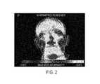
- FIG. 2is an thermal image of the head and face which illustrates pixel temperature differences of various extremities of the subject's head and face;
- FIG. 3is an illustration of a head and face showing a plurality of locational relationships (indicated by vectors and angles) associated with a human head which are used in accordance herewith to isolate the location of facial features associated with respiration, i.e., a nose and mouth;
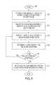
- FIG. 4is a flow diagram which illustrates one example embodiment of the present method for monitoring respiration using a thermal imaging system
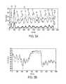
- FIG. 5Ashows a normal breathing pattern obtained by tracking R,G,B intensity values received from a thermal camera's R, G, and B channels, respectively;
- FIG. 5Bshows an abnormal respiration pattern where the test subject was instructed to hold their breath for about 20 sec
- FIG. 6shows an example of respiration being tracked by a movement of the subject's nasal area
- FIG. 7is a block diagram of an example networked respiration monitoring system capable of implementing various aspects of the present method as described with respect to the flow diagram of FIG. 4 .
- What is disclosedis a system and method for capturing a video sequence of a subject of interest and automatically processing those captured thermal images such that the subject's respiratory function can be continuously and safely monitored without any contact sensors on the subject.
- a “subject of interest, as used herein,is intended to encompass any living creature which has a facial feature associated with respiration.
- Respirationis a process of inhaling of air into lungs and exhaling air out of the lungs followed by a post-expiratory pause.
- Inhalationis an active process caused by a negative pressure having been induced in the chest cavity by the contraction of a relatively large muscle (often called the diaphragm) which changes pressure in the lungs by a forcible expansion of the lung's alveolar cells.
- Exhalationis a passive process where air is expelled from the lungs by the natural elastic recoil of the stretched alveolar cells.
- the lining of alveolar cellshave a surface-active phospholipoprotein complex which causes the lining to naturally contract back to a neutral state once the external force causing the cell to stretch has released.
- a post-expiratory pauseoccurs when there is an equalization of pressure between the lungs and the atmosphere.
- the duration of the post-expiratory pausecan be relatively long.
- the duration of the post-expiratory pausereduces with increased physical activity and may even fall to zero at very high rates of exertion.
- FIGS. 1( a ) and 1 ( b )show a typical duration of the three phases of breathing during inactivity and after physical exertion.
- a “breathing cycle”is the time interval between the beginning of inhalation and the end of the post-expiratory pause. Immediately following the post-expiratory pause is the start of the next breathing cycle.
- An “extremity of the head and face”refers to a physical feature of the head and face of the subject of interest which may be isolated in a thermal image as a result of a temperature difference.
- Head and face extremitiescan include: ears, tip of the chin, tip of the nose, cheeks, and the like. Extremities of the head and face are used herein to determine a location of the subject's facial feature associated with respiration. In the image of FIG. 2 , the ears are used to locate the mouth/nose (facial feature associated with respiration).
- a “facial feature associated with respiration”refers to an air passageway through which oxygenated air is received into the lungs during inhalation and carbon-dioxide rich air is expelled out of the lungs during exhalation. Facial features associated with respiration are determined in the thermal images by various pre-defined locational relationships.
- a “locational relationship”refers to information about the location of a subject's extremities of the head and face which are used in accordance herewith to facilitate a determination of a location of the subject's facial features associated with respiration.
- Locational relationshipscan have many forms such as for example, vectors, angles, distances, formulas, text, images, and the like.
- facial features associated with respirationare their nose and mouth.
- the nosefor example, can be located in the thermal image by using the location of the eyes or relative to the location of the ears.
- the mouthcan be located in the thermal image relative to the location of the ears and chin.
- Pre-defined locational relationships of facial features of different known subjects of interestare stored in a database.
- Example locational relationshipswhich can be stored in a database as vectors and angles are shown in FIG. 3 are used to isolate the mouth 301 and nostrils, collectively at 302 . Locational relationships are used herein to facilitate a determination of the location of the facial feature associated with respiration such that a respiration pattern can be determined.
- a “respiration pattern”refers to the subject's breathing cycle tracked over time.
- the pattern of respirationis obtained by tracking pixel values of one or more facial features associated with respiration over time.
- Example respiration patternsare shown and discussed with respect to FIGS. 5A-B .
- the patternusually shows periodic peaks and valleys associated with respiration cycles.
- a “respiration rate”is the number of breathing cycles a subject takes within a certain amount of time (typically given in breaths/minute). Respiration rate is often measured when a subject is at rest and simply involves counting the number of breaths taking in a minute. During physical exertion when the body requires oxygenation at an increased rate, the respiration rate increases. Respiration rates may increase without physical activity due to fever, for example, or other medical conditions.
- the following chartshows average human respiration rates by age:
- thermal imageor “thermal image video sequence” is an image or sequence of images captured using a thermal camera.
- Each thermal imagecomprises a plurality of pixels each corresponding to a surface temperature of a facial region across a thermal wavelength band. It should be understood that the teachings hereof are directed to image captured in the infrared wavelength range of: ⁇ 7500 nm to ⁇ 14,000 nm.
- thermo cameraor “thermal image video system” is a camera system capable of capturing thermal images of a subject of interest. Specialized processors inside the thermal camera associate pixel color values with different temperatures and provide output RGB values of each pixel in the output image.
- the resolution for a thermal camerais effectively the size of the pixel. Smaller pixels mean that more pixels will go into the image giving the resulting image higher resolution and thus better definition. Because the amount of black-body radiation emitted by an object increases with the object's temperature, variations in temperatures of differing objects are observable in a thermal image.
- Thermal camerasgenerally consist of five primary components: 1) optics comprising specialized focal plane arrays (FPAs) that respond to defined wavelengths of the infrared range of the electromagnetic (EM) spectrum ( ⁇ 7.5 to ⁇ 14 ⁇ m); 2) a detector for detecting radiation in the infrared range; 3) an amplifier for amplifying the received radiation; 4) a display for viewing the captured images; and 5) signal processing hardware such as: a CPU, memory, storage, for performing mathematical algorithms which interpret data and construct an IR image.
- FPAsfocal plane arrays
- EMelectromagnetic
- Standard IR filmis sensitive to a 250° C. to 500° C. variation.
- Thermal camera systemsoffer a relatively large dynamic range of temperature settings. However, for the purposes hereof, it is preferable that the camera's temperature range be relatively small ⁇ 23.8° C. to ⁇ 33.8° C., so that small temperature variations can be amplified in terms of pixel color changes. A smaller temperature range provides a better measure of temperature variation which, in turn, enables easier feature identification and location.
- Thermal camera systemsare readily available in various streams of commerce.
- FIG. 4illustrates one example embodiment of the present method for monitoring respiration using a thermal imaging system.
- Flow processingbegins at 400 and immediately proceeds to step 402 .
- thermal images of a subject of interestare captured using a thermal camera set to a temperature of a facial region of the subject.
- Each thermal image in the image sequencecomprises a plurality of pixels with each pixel corresponding to a surface temperature of the facial region across the camera's thermal wavelength band.
- One example thermal imageis shown in FIG. 2 .
- the thermal imagesare analyzed to determine at least one facial feature associated with respiration. Analyzing the thermal images to determine the facial feature(s) associated with respiration involves identifying a location of at least one extremity of the subject's head and face. Once the locations of the extremities have been identified, the facial feature associated with respiration can be isolated in the thermal image relative to those location(s). In one embodiment, locational relationships are retrieved from a database and the location of the facial features associated with respiration is determined using the retrieved locational relationships. Once the facial features associated with respiration have been isolated in the thermal image, processing proceeds with respect to step 406 .
- the location of the subject's facial features associated with respirationis tracked over time to determine a pattern of respiration.
- identifying a pattern of respirationinvolves tracking some or all of the R, G, B, values obtained from the R, G, B, channels of the camera of pixels of image regions associated with the facial feature locations.
- An example plotted curves of normal and abnormal patterns of respirationare shown in FIGS. 5A and 5B , respectively. It should be appreciated that the R and G channels ( 501 and 502 , respectively) are more useful than the B channel 503 , as can be clearly seen in the curve of FIG.
- a respiration rateis determined from the respiration pattern. Determining the respiration rate involves analyzing the plotted curve of R, G, B color values and counting the number of peaks over a pre-defined amount of time using methods such as Fourier transform or direct peak-valley detection algorithm. For example, from FIG. 5A , a total of 12 peaks can be counted in a 60 second window (filming at approximately 1800 frames/minute). As can be seen from the above-described Table, this correlates well to the number of breaths an adult subject would take in a minute and in the experiment, the rate was consistent with our visual counting of the number of inhales/exhales from the subject.
- respiration rateis determined by the motion of the nostrils, lips, or chest.
- FIG. 6shows the respiration rate (12 breaths/minute) obtained by tracking the motion of the nostrils over a plurality of breathing cycles. This motion can be separated from other physical motion as movement in the image due to a respiratory function tends to be periodic at a certain frequency while other types of physical motion tends to be irregular.
- a visual comparison of the plots of FIGS. 5A and 6show that, even though the phase is different, the number of peaks/valleys (breaths/minute) are approximately the same, using either technique.
- the respiration patternhas to be closely monitored, e.g., the amplitude of the peaks/valleys and period of each cycle. For example, significantly reduced amplitude or the amplitude is below a threshold can indicate abnormal breathing patterns.
- the respiration pattern from a certain time periodcan be compared with the subject's normal breath pattern retrieved from a database. Methods such as Dynamic Time Warping (DTW) or Longest Common Subsequence (LCSS) can be used to compare the time sequence.
- DTWDynamic Time Warping
- LCSSLongest Common Subsequence
- an alarmis initiated which indicates that the subject's respiration rate or respiration pattern is not acceptable.
- Initiating an alarmcan be, for example, activating a light or audible noise, or otherwise producing a signal which activates a device which, in turns, performs an action or provides a notification.
- the kind of alarm signal being generatedwill depend on the particular embodiment wherein the teachings hereof are implemented.
- processingrepeats with respect to step 406 the subject's respiration pattern is continuously monitored despite the alarm.
- a signalcan be sent indicating delayed breathing or a change in heart rate.
- the present systemcan be used in conjunction with other health monitoring equipment or integrated therewith such that the initiated alarm signal causes these other device to perform intended functions.
- One example system for continuously processing the thermal images in accordance with the teachings hereofis described with respect to the block diagram of FIG. 7 .
- FIG. 7is a block diagram of one example respiration monitoring system for implementing various aspects of the present method as described with respect to the flow diagram of FIG. 4 .
- thermal camera 702captures a thermal image video sequence of a subject of interest whose head and face are in the camera's field of view 703 .
- the captured videois continuously communicated to image processing system 704 along with R, G, B values obtained from the camera's RGB output channels.
- Image Processing System 704is shown comprising a Buffer 706 for queuing the received thermal images for processing. Buffer 706 may further store data and mathematical formulas and representations as necessary to process the images according to various embodiments hereof.
- RGB Signal Processor 708receives the RGB signals from respective RGB channels of thermal camera 702 and processes the pixel data to ensure that the pixel color values are within a predefined range and to associate pixels values with image areas within the frame.
- An Image Stabilizer 710is provided for those systems where noise in the video sequence from either the motion of the camera or movement of the subject needs to be compensated for using, for example, image segmentation and point feature tracking. Such techniques are well known in the image processing arts.
- the thermal images and RGB valuesare provided to Extremity Locator Module 712 which identifies extremities of the subject's head and face.
- Facial Feature Location Module 716receives the identified head and face extremities from Module 712 and locational relationships are retrieved from database 714 and used to determine a location of the subject's facial features associated with respiration.
- Respiration Pattern Generator 718uses the RGB values associated with the location of the identified facial features and generates a respiration pattern which is stored to Memory 720 .
- the generated respiration patternis provided to Respiration Rate Processor 722 which determines the subject's rate of respiration by counting the number of peaks and valleys in the pattern over time. Respiration Rate Processor 722 is also in communication with Memory 720 . The generated respiration rate and/or respiration pattern are provided to Threshold Comparator Module 725 which, in turn, determines whether the respiration rate or respiratory pattern is within acceptable parameters. Comparator 725 is in communication with Alert Signal Generator 726 which outputs a signal 727 if either the respiration rate or respiration pattern fall outside a pre-defined threshold level. Various portions of the captured IR image sequence and/or the RGB values obtained from camera 702 may be stored to Memory 720 and/or Storage Device 714 or may be communicated to Workstation 728 for storage or processing.
- workstation 728shown in communication with network 730 via a communications interface (not shown).
- workstation 728is shown comprising a display monitor 732 for displaying information and for effectuating a user input or selection.
- Display 732may be placed in communication with image processor system 704 and/or thermal video camera system 702 such that thermal images obtained by camera 702 can be viewed on the monitor display.
- FIG. 7may use the graphical user interface of workstation 728 , e.g., keyboard 734 and mouse 736 , to identify or select pixels, frames, images, and/or regions of interest for processing. These may be stored and/or retrieved from storage medium 738 or to computer readable media 740 . Information stored to media 740 can be retrieved by a media reader such as, for example, a CD-ROM drive, located inside of computer case 742 . Any of the modules and processing units of FIG. 7 can be placed in communication with database 738 and may store/retrieve therefrom data, variables, records, parameters, functions, machine readable/executable program instructions required to perform their intended functions. Moreover each of the modules of system 704 may be placed in communication with one or more devices over network 730 .
- a media readersuch as, for example, a CD-ROM drive
- modulesmay designate one or more components which may, in turn, comprise software and/or hardware designed to perform the intended function.
- a plurality of modulesmay collectively perform a single function.
- Each modulemay have a specialized processor capable of executing machine readable program instructions.
- a modulemay comprise a single piece of hardware such as an ASIC, electronic circuit, or special purpose processor.
- a plurality of modulesmay be executed by either a single special purpose computer system or a plurality of special purpose computer systems in parallel. Connections between modules include both physical and logical connections.
- Modulesmay further include one or more software/hardware modules which may further comprise an operating system, drivers, device controllers, and other apparatuses some or all of which may be connected via a network.
- one or more aspects of the present methodmay be implemented on a dedicated computer system and may also be practiced in distributed computing environments where tasks are performed by remote devices that are linked through a network.
- the teachings hereofcan be implemented in hardware or software using any known or later developed systems, structures, devices, and/or software by those skilled in the applicable art without undue experimentation from the functional description provided herein with a general knowledge of the relevant arts.
- a computer usable or machine readable mediais, for example, a floppy disk, a hard-drive, memory, CD-ROM, DVD, tape, cassette, or other digital or analog media, or the like, which is capable of having embodied thereon a computer readable program, one or more logical instructions, or other machine executable codes or commands that implement and facilitate the function, capability, and methodologies described herein.
- the article of manufacturemay be included on at least one storage media readable by a machine architecture or image processing system embodying executable program instructions capable of performing the methodology described in the flow diagrams. Additionally, the article of manufacture may be included as part of an operating system, a plug-in, or may be shipped, sold, leased, or otherwise provided separately, either alone or as part of an add-on, update, upgrade, or product suite.
Landscapes
- Health & Medical Sciences (AREA)
- Life Sciences & Earth Sciences (AREA)
- Biomedical Technology (AREA)
- Heart & Thoracic Surgery (AREA)
- Veterinary Medicine (AREA)
- Biophysics (AREA)
- Pathology (AREA)
- Engineering & Computer Science (AREA)
- Public Health (AREA)
- Physics & Mathematics (AREA)
- Medical Informatics (AREA)
- Molecular Biology (AREA)
- Surgery (AREA)
- Animal Behavior & Ethology (AREA)
- General Health & Medical Sciences (AREA)
- Physiology (AREA)
- Pulmonology (AREA)
- Measurement Of The Respiration, Hearing Ability, Form, And Blood Characteristics Of Living Organisms (AREA)
Abstract
Description
| <1 Year: 30-40 breaths per minute | ||
| 1-3 Years: 23-35 breaths per minute | ||
| 3-6 Years: 20-30 breaths per minute | ||
| 6-12 Years: 18-26 breaths per minute | ||
| 12-17 Years: 12-20 breaths per minute | ||
| Over 18: 12-20 breaths per minute | ||
Claims (25)
Priority Applications (1)
| Application Number | Priority Date | Filing Date | Title |
|---|---|---|---|
| US13/103,406US8790269B2 (en) | 2011-05-09 | 2011-05-09 | Monitoring respiration with a thermal imaging system |
Applications Claiming Priority (1)
| Application Number | Priority Date | Filing Date | Title |
|---|---|---|---|
| US13/103,406US8790269B2 (en) | 2011-05-09 | 2011-05-09 | Monitoring respiration with a thermal imaging system |
Publications (2)
| Publication Number | Publication Date |
|---|---|
| US20120289850A1 US20120289850A1 (en) | 2012-11-15 |
| US8790269B2true US8790269B2 (en) | 2014-07-29 |
Family
ID=47142337
Family Applications (1)
| Application Number | Title | Priority Date | Filing Date |
|---|---|---|---|
| US13/103,406Active2032-05-15US8790269B2 (en) | 2011-05-09 | 2011-05-09 | Monitoring respiration with a thermal imaging system |
Country Status (1)
| Country | Link |
|---|---|
| US (1) | US8790269B2 (en) |
Cited By (14)
| Publication number | Priority date | Publication date | Assignee | Title |
|---|---|---|---|---|
| US9697599B2 (en) | 2015-06-17 | 2017-07-04 | Xerox Corporation | Determining a respiratory pattern from a video of a subject |
| US10219739B2 (en) | 2013-10-02 | 2019-03-05 | Xerox Corporation | Breathing pattern identification for respiratory function assessment |
| US10292369B1 (en) | 2015-06-30 | 2019-05-21 | Vium, Inc. | Non-contact detection of physiological characteristics of experimental animals |
| US10327708B2 (en) | 2013-01-24 | 2019-06-25 | Kineticor, Inc. | Systems, devices, and methods for tracking and compensating for patient motion during a medical imaging scan |
| US10339654B2 (en) | 2013-01-24 | 2019-07-02 | Kineticor, Inc. | Systems, devices, and methods for tracking moving targets |
| US20190200937A1 (en)* | 2016-08-23 | 2019-07-04 | Koninklijke Philips N.V. | Device, system and method for detection of an asthma attack or asthma of a subject |
| US10438349B2 (en) | 2014-07-23 | 2019-10-08 | Kineticor, Inc. | Systems, devices, and methods for tracking and compensating for patient motion during a medical imaging scan |
| US10663553B2 (en) | 2011-08-26 | 2020-05-26 | Kineticor, Inc. | Methods, systems, and devices for intra-scan motion correction |
| US10660541B2 (en) | 2015-07-28 | 2020-05-26 | The University Of Hawai'i | Systems, devices, and methods for detecting false movements for motion correction during a medical imaging scan |
| US10716515B2 (en) | 2015-11-23 | 2020-07-21 | Kineticor, Inc. | Systems, devices, and methods for tracking and compensating for patient motion during a medical imaging scan |
| US10869611B2 (en) | 2006-05-19 | 2020-12-22 | The Queen's Medical Center | Motion tracking system for real time adaptive imaging and spectroscopy |
| US10943092B2 (en) | 2018-05-23 | 2021-03-09 | ClairLabs Ltd. | Monitoring system |
| US11589776B2 (en) | 2018-11-06 | 2023-02-28 | The Regents Of The University Of Colorado | Non-contact breathing activity monitoring and analyzing through thermal and CO2 imaging |
| US12279857B2 (en) | 2021-04-01 | 2025-04-22 | Hill-Rom Services, Inc. | Video used to estimate vital signs |
Families Citing this family (47)
| Publication number | Priority date | Publication date | Assignee | Title |
|---|---|---|---|---|
| US20200168331A1 (en) | 2012-03-02 | 2020-05-28 | Leonard Solie | Clinician station for providing medical services remotely |
| US11978552B2 (en) | 2012-03-02 | 2024-05-07 | Md Health Rx Solutions, Llc | Medical services kiosk |
| US11984228B1 (en) | 2012-03-02 | 2024-05-14 | Md Health Rx Solutions, Llc | Medical service kiosk having an integrated scale |
| US12322517B2 (en) | 2012-03-02 | 2025-06-03 | Onmed Llc | Medical services method and system |
| US11083344B2 (en) | 2012-10-11 | 2021-08-10 | Roman Tsibulevskiy | Partition technologies |
| US8792969B2 (en)* | 2012-11-19 | 2014-07-29 | Xerox Corporation | Respiratory function estimation from a 2D monocular video |
| JP2014171574A (en)* | 2013-03-07 | 2014-09-22 | Sharp Corp | Device, system and method each for monitoring respiration |
| US10292623B2 (en) | 2013-03-15 | 2019-05-21 | Koninklijke Philips N.V. | Apparatus and method for determining a respiration volume signal from image data |
| CN104173051A (en)* | 2013-05-28 | 2014-12-03 | 天津点康科技有限公司 | Automatic noncontact respiration assessing system and assessing method |
| JP6205901B2 (en)* | 2013-06-28 | 2017-10-04 | カシオ計算機株式会社 | Measuring device, measuring method and program |
| WO2015030611A1 (en)* | 2013-09-02 | 2015-03-05 | Interag | Method and apparatus for determining respiratory characteristics of an animal |
| US10201293B2 (en) | 2013-09-11 | 2019-02-12 | Xerox Corporation | Non-contact monitoring of spatio-temporal respiratory mechanics via depth sensing |
| DE102013219232A1 (en)* | 2013-09-25 | 2015-03-26 | Siemens Aktiengesellschaft | Method and device for determining a respiratory motion of an examination object |
| JP6371837B2 (en) | 2013-10-17 | 2018-08-08 | コーニンクレッカ フィリップス エヌ ヴェKoninklijke Philips N.V. | Devices and methods for obtaining vital signs of subjects |
| CN105705089B (en) | 2013-11-01 | 2019-12-24 | 皇家飞利浦有限公司 | System and method for determining vital sign information of a subject |
| US9514537B2 (en) | 2013-12-27 | 2016-12-06 | Xerox Corporation | System and method for adaptive depth map reconstruction |
| US9875664B2 (en) | 2014-06-02 | 2018-01-23 | Xerox Corporation | Virtual trainer optimizer method and system |
| EP3799782B1 (en)* | 2014-12-02 | 2023-04-19 | Brainlab AG | Human body measurement using thermographic images |
| US20190236775A1 (en)* | 2014-12-19 | 2019-08-01 | Woundvision, Llc | Method of Monitoring the Status of a Wound |
| WO2016164904A1 (en)* | 2015-04-10 | 2016-10-13 | Ivan Arbouzov | Multi-sensor, modular, subject observation and monitoring system |
| JP6631783B2 (en)* | 2015-11-19 | 2020-01-15 | エア・ウォーター・バイオデザイン株式会社 | Measuring system and measuring method for measuring life activity caused by respiration of subject |
| CN106361340B (en)* | 2016-08-30 | 2019-05-31 | 苏州涵轩信息科技有限公司 | A kind of method and device detecting respiratory rate |
| US11389119B2 (en)* | 2016-09-06 | 2022-07-19 | Photorithm, Inc. | Generating a breathing alert |
| US10709354B2 (en)* | 2016-09-06 | 2020-07-14 | Photorithm, Inc. | Generating a breathing alert |
| KR101868782B1 (en)* | 2016-10-28 | 2018-07-23 | 아주대학교산학협력단 | respiratory analysis measurement system using gas imaging detection technique |
| KR101869225B1 (en)* | 2016-11-15 | 2018-06-19 | 성균관대학교산학협력단 | Paradoxical pulse detection method using image and paradoxical pulse detection apparatus using image |
| KR101978900B1 (en)* | 2017-04-11 | 2019-05-15 | 성균관대학교산학협력단 | Apparatus, and method for examining pulmonary function using face image, and computer readable recording medium for recoring the same |
| KR101996996B1 (en)* | 2017-07-13 | 2019-07-05 | 성균관대학교산학협력단 | Method And Apparatus For Measuring Bio-Signal Using Infrared Image |
| WO2019162459A1 (en)* | 2018-02-23 | 2019-08-29 | Alunos Ag | Monitoring of physiological parameters |
| EP4040424A1 (en) | 2018-05-29 | 2022-08-10 | Curiouser Products Inc. | A reflective video display apparatus for interactive training and demonstration and methods of using same |
| US20200155040A1 (en) | 2018-11-16 | 2020-05-21 | Hill-Rom Services, Inc. | Systems and methods for determining subject positioning and vital signs |
| JP6747493B2 (en)* | 2018-11-28 | 2020-08-26 | 株式会社デンソー | Driver status determination device |
| CN110731778B (en)* | 2019-07-22 | 2022-04-29 | 华南师范大学 | Method and system for recognizing breathing sound signal based on visualization |
| US20210127989A1 (en)* | 2019-09-27 | 2021-05-06 | Andres Nicolas Atamañuk | Method of estimation of the hemodynamic status and capacity of effort from patients with cardiovascular and pulmonar diseases |
| US11562489B2 (en)* | 2019-12-02 | 2023-01-24 | Purdue Research Foundation | Pixel-wise hand segmentation of multi-modal hand activity video dataset |
| CN111387957B (en)* | 2020-03-13 | 2023-03-24 | 智方达(天津)科技有限公司 | Non-contact type body temperature and respiration rate combined detection method |
| CN115485753A (en) | 2020-04-30 | 2022-12-16 | 库里欧瑟产品公司 | Reflective video display device and method of use for interactive training and demonstration |
| IL275524B (en) | 2020-06-18 | 2021-12-01 | Elbit Systems C4I & Cyber Ltd | Contactless parameters measurement system and method |
| US11167172B1 (en) | 2020-09-04 | 2021-11-09 | Curiouser Products Inc. | Video rebroadcasting with multiplexed communications and display via smart mirrors |
| US20220133156A1 (en)* | 2020-10-29 | 2022-05-05 | Roc8Sci Co. | Cardiopulmonary health monitoring using thermal camera and audio sensor |
| CN113576452A (en)* | 2021-07-30 | 2021-11-02 | 深圳市商汤科技有限公司 | Respiration rate detection method and device based on thermal imaging and electronic equipment |
| CN113576451A (en)* | 2021-07-30 | 2021-11-02 | 深圳市商汤科技有限公司 | Respiration rate detection method and device, storage medium and electronic equipment |
| CN113793300A (en)* | 2021-08-19 | 2021-12-14 | 合肥工业大学 | Non-contact type respiration rate detection method based on thermal infrared imager |
| DE102022001947A1 (en) | 2022-06-03 | 2023-12-14 | Cubical GmbH | Image processing platform for contactless monitoring of intensive care patients |
| KR20240065856A (en)* | 2022-11-07 | 2024-05-14 | 아이쓰리시스템 주식회사 | System for diagnosing sleep apnea using ir camera and method the same |
| US20240268711A1 (en)* | 2023-02-13 | 2024-08-15 | Samsung Electronics Co., Ltd. | Contactless monitoring of respiratory rate and breathing absence using face video |
| WO2025188356A1 (en)* | 2023-09-12 | 2025-09-12 | Battelle Memorial Institute | Systems and methods for predicting a condition requiring a life-saving intervention including leveraging contextual information and information on reliability of input data streams |
Citations (17)
| Publication number | Priority date | Publication date | Assignee | Title |
|---|---|---|---|---|
| US5010890A (en)* | 1983-08-11 | 1991-04-30 | Vitacomm, Ltd. | Vital signs monitoring system |
| US5107845A (en) | 1987-11-23 | 1992-04-28 | Bertin & Cie | Method and device for monitoring human respiration |
| US5800360A (en) | 1992-02-11 | 1998-09-01 | Spectrum Medical Technologies, Inc. | Apparatus and method for respiratory monitoring |
| US20020008758A1 (en)* | 2000-03-10 | 2002-01-24 | Broemmelsiek Raymond M. | Method and apparatus for video surveillance with defined zones |
| US6920236B2 (en) | 2001-03-26 | 2005-07-19 | Mikos, Ltd. | Dual band biometric identification system |
| US6958809B2 (en) | 2001-11-08 | 2005-10-25 | Optiscan Biomedical Corporation | Reagent-less whole-blood glucose meter |
| US6989891B2 (en) | 2001-11-08 | 2006-01-24 | Optiscan Biomedical Corporation | Device and method for in vitro determination of analyte concentrations within body fluids |
| US7050157B2 (en) | 2001-11-08 | 2006-05-23 | Optiscan Biomedical Corp. | Reagent-less whole-blood glucose meter |
| US7061593B2 (en) | 2001-11-08 | 2006-06-13 | Optiscan Biomedical Corp. | Device and method for in vitro determination of analyte concentrations within body fluids |
| US7436510B2 (en) | 2004-01-07 | 2008-10-14 | The United States Of America As Represented By The Secretary Of The Navy | Method and apparatus for identifying a substance using a spectral library database |
| US7570979B2 (en) | 2004-03-30 | 2009-08-04 | Philip George Cooper | Methods and apparatus for patient monitoring |
| US20090275808A1 (en) | 2008-04-30 | 2009-11-05 | Board Of Regents, The University Of Texas System | Integrated patient bed system |
| US20090318815A1 (en) | 2008-05-23 | 2009-12-24 | Michael Barnes | Systems and methods for hyperspectral medical imaging |
| US7729750B2 (en) | 2005-01-20 | 2010-06-01 | The Regents Of The University Of California | Method and apparatus for high resolution spatially modulated fluorescence imaging and tomography |
| US7760354B2 (en) | 2005-01-07 | 2010-07-20 | The United States Of America As Represented By The Secretary Of The Navy | Spectroscopic method and apparatus for identification of a substance using a tunable light source |
| US7899764B2 (en) | 2007-02-16 | 2011-03-01 | Siemens Aktiengesellschaft | Medical ontologies for machine learning and decision support |
| US7896498B2 (en) | 2009-03-30 | 2011-03-01 | Ottawa Hospital Research Institute | Apparatus and method for optical measurements |
- 2011
- 2011-05-09USUS13/103,406patent/US8790269B2/enactiveActive
Patent Citations (20)
| Publication number | Priority date | Publication date | Assignee | Title |
|---|---|---|---|---|
| US5010890A (en)* | 1983-08-11 | 1991-04-30 | Vitacomm, Ltd. | Vital signs monitoring system |
| US5107845A (en) | 1987-11-23 | 1992-04-28 | Bertin & Cie | Method and device for monitoring human respiration |
| US5800360A (en) | 1992-02-11 | 1998-09-01 | Spectrum Medical Technologies, Inc. | Apparatus and method for respiratory monitoring |
| US20020008758A1 (en)* | 2000-03-10 | 2002-01-24 | Broemmelsiek Raymond M. | Method and apparatus for video surveillance with defined zones |
| US6920236B2 (en) | 2001-03-26 | 2005-07-19 | Mikos, Ltd. | Dual band biometric identification system |
| US7480032B2 (en) | 2001-11-08 | 2009-01-20 | Optiscan Biomedical Corporation | Device and method for in vitro determination of analyte concentrations within body fluids |
| US7738085B2 (en) | 2001-11-08 | 2010-06-15 | Optiscan Biomedical Corporation | Device and method for in vitro determination of analyte concentration within body fluids |
| US7050157B2 (en) | 2001-11-08 | 2006-05-23 | Optiscan Biomedical Corp. | Reagent-less whole-blood glucose meter |
| US7061593B2 (en) | 2001-11-08 | 2006-06-13 | Optiscan Biomedical Corp. | Device and method for in vitro determination of analyte concentrations within body fluids |
| US6989891B2 (en) | 2001-11-08 | 2006-01-24 | Optiscan Biomedical Corporation | Device and method for in vitro determination of analyte concentrations within body fluids |
| US6958809B2 (en) | 2001-11-08 | 2005-10-25 | Optiscan Biomedical Corporation | Reagent-less whole-blood glucose meter |
| US7872734B2 (en) | 2001-11-08 | 2011-01-18 | Optiscan Biomedical Corporation | In vitro determination of analyte levels within body fluids |
| US7436510B2 (en) | 2004-01-07 | 2008-10-14 | The United States Of America As Represented By The Secretary Of The Navy | Method and apparatus for identifying a substance using a spectral library database |
| US7570979B2 (en) | 2004-03-30 | 2009-08-04 | Philip George Cooper | Methods and apparatus for patient monitoring |
| US7760354B2 (en) | 2005-01-07 | 2010-07-20 | The United States Of America As Represented By The Secretary Of The Navy | Spectroscopic method and apparatus for identification of a substance using a tunable light source |
| US7729750B2 (en) | 2005-01-20 | 2010-06-01 | The Regents Of The University Of California | Method and apparatus for high resolution spatially modulated fluorescence imaging and tomography |
| US7899764B2 (en) | 2007-02-16 | 2011-03-01 | Siemens Aktiengesellschaft | Medical ontologies for machine learning and decision support |
| US20090275808A1 (en) | 2008-04-30 | 2009-11-05 | Board Of Regents, The University Of Texas System | Integrated patient bed system |
| US20090318815A1 (en) | 2008-05-23 | 2009-12-24 | Michael Barnes | Systems and methods for hyperspectral medical imaging |
| US7896498B2 (en) | 2009-03-30 | 2011-03-01 | Ottawa Hospital Research Institute | Apparatus and method for optical measurements |
Non-Patent Citations (9)
| Title |
|---|
| Al-Khalidi, et al., "Tracking Human Face Features in Thermal Images for Respiration Monitoring", IEEE/ACS Int'l Conf. on Computer Systems and Applications (AICCSA), Hammamet, Tunisia, (May 16-19, 2010). |
| Aoki, et al., "Study on Respiration Monitoring Method Using Near-infrared Multiple Slit-lights Projection", IEEE International Symposium on Micro-NanoMechatronics and Human Science, pp. 291-296, (Nov. 7-9, 2005), ISBN: 0-7803-9482-8. |
| Aoki, et al., Non-contact and Unrestrained Respiration Monitoring System for Sleeping Person Using Near-infrared Bright Spots Matrix Irradiation, IEEJ Transactions on Electronics, pp. 1251-1258, vol. 124, No. 6, (Sep. 2004). |
| Eveland, et al., "Tracking Human Faces in Infrared Video", Image and Vision Computing, vol. 21, pp. 579-590 (2003). |
| Fei, et al., Analysis of Breathing Air Flow Patterns in Thermal Imaging, Proceedings of the 28th IEEE EMBS Annual International Conference, New York City, USA, pp. 946-952, (Aug. 30-Sep. 3, 2006). |
| Moore, David, "A Real-World System for Human Motion Detection and Tracking", Final Thesis, California Institute of Technology, (2003). |
| Murthy, et al., Non-Contact Monitoring of Breathing Function Using Infrared Imaging, pp. 1-17, Technical Report No. UH-CS-05-09, Apr. 9, 2005. |
| Takeo Kanade, Computer Recognition of Human Faces, 1977, Birkhäuser Verlag, Basel und Stuttgart.* |
| Wang, et al., "Intelligent Multimodal and Hyperspectral Sensing for Real-Time Moving Target Tracking", Applied Imagery Pattern Recognition Workshop (AIPR), pp. 1-8, (2008). |
Cited By (16)
| Publication number | Priority date | Publication date | Assignee | Title |
|---|---|---|---|---|
| US10869611B2 (en) | 2006-05-19 | 2020-12-22 | The Queen's Medical Center | Motion tracking system for real time adaptive imaging and spectroscopy |
| US10663553B2 (en) | 2011-08-26 | 2020-05-26 | Kineticor, Inc. | Methods, systems, and devices for intra-scan motion correction |
| US10327708B2 (en) | 2013-01-24 | 2019-06-25 | Kineticor, Inc. | Systems, devices, and methods for tracking and compensating for patient motion during a medical imaging scan |
| US10339654B2 (en) | 2013-01-24 | 2019-07-02 | Kineticor, Inc. | Systems, devices, and methods for tracking moving targets |
| US10219739B2 (en) | 2013-10-02 | 2019-03-05 | Xerox Corporation | Breathing pattern identification for respiratory function assessment |
| US11100636B2 (en) | 2014-07-23 | 2021-08-24 | Kineticor, Inc. | Systems, devices, and methods for tracking and compensating for patient motion during a medical imaging scan |
| US10438349B2 (en) | 2014-07-23 | 2019-10-08 | Kineticor, Inc. | Systems, devices, and methods for tracking and compensating for patient motion during a medical imaging scan |
| US9697599B2 (en) | 2015-06-17 | 2017-07-04 | Xerox Corporation | Determining a respiratory pattern from a video of a subject |
| US10292369B1 (en) | 2015-06-30 | 2019-05-21 | Vium, Inc. | Non-contact detection of physiological characteristics of experimental animals |
| US10660541B2 (en) | 2015-07-28 | 2020-05-26 | The University Of Hawai'i | Systems, devices, and methods for detecting false movements for motion correction during a medical imaging scan |
| US10716515B2 (en) | 2015-11-23 | 2020-07-21 | Kineticor, Inc. | Systems, devices, and methods for tracking and compensating for patient motion during a medical imaging scan |
| US10925548B2 (en)* | 2016-08-23 | 2021-02-23 | Koninklijke Philips N.V. | Device, system and method for detection of an asthma attack or asthma of a subject |
| US20190200937A1 (en)* | 2016-08-23 | 2019-07-04 | Koninklijke Philips N.V. | Device, system and method for detection of an asthma attack or asthma of a subject |
| US10943092B2 (en) | 2018-05-23 | 2021-03-09 | ClairLabs Ltd. | Monitoring system |
| US11589776B2 (en) | 2018-11-06 | 2023-02-28 | The Regents Of The University Of Colorado | Non-contact breathing activity monitoring and analyzing through thermal and CO2 imaging |
| US12279857B2 (en) | 2021-04-01 | 2025-04-22 | Hill-Rom Services, Inc. | Video used to estimate vital signs |
Also Published As
| Publication number | Publication date |
|---|---|
| US20120289850A1 (en) | 2012-11-15 |
Similar Documents
| Publication | Publication Date | Title |
|---|---|---|
| US8790269B2 (en) | Monitoring respiration with a thermal imaging system | |
| JP6371837B2 (en) | Devices and methods for obtaining vital signs of subjects | |
| US9697599B2 (en) | Determining a respiratory pattern from a video of a subject | |
| JP6616331B2 (en) | Apparatus, system and method for detecting apnea in a subject | |
| US9336594B2 (en) | Cardiac pulse rate estimation from source video data | |
| CN102869305B (en) | Respiratory motion detection device | |
| KR102054213B1 (en) | Respiratory measurement system using thermovision camera | |
| US20230233091A1 (en) | Systems and Methods for Measuring Vital Signs Using Multimodal Health Sensing Platforms | |
| CN105869144A (en) | Depth image data-based non-contact respiration monitoring method | |
| Basu et al. | Infrared imaging based hyperventilation monitoring through respiration rate estimation | |
| Chatterjee et al. | Real-time respiration rate measurement from thoracoabdominal movement with a consumer grade camera | |
| Gwak et al. | Motion-based respiratory rate estimation with motion artifact removal using video of face and upper body | |
| CN112806966A (en) | Non-interference type early warning system and method for apnea in sleep | |
| US20230293113A1 (en) | System and method of estimating vital signs of user using artificial intelligence | |
| Chen et al. | Collaborative use of RGB and thermal imaging for remote breathing rate measurement under realistic conditions | |
| Liu et al. | Detecting pulse wave from unstable facial videos recorded from consumer-level cameras: A disturbance-adaptive orthogonal matching pursuit | |
| Mateu-Mateus et al. | Comparison of video-based methods for respiration rhythm measurement | |
| EP2962282A1 (en) | Apparatus and method for detecting subjects on the basis of vital signs | |
| Rumiński | Evaluation of the respiration rate and pattern using a portable thermal camera | |
| Usman et al. | Non-invasive respiration monitoring by thermal imaging to detect sleep apnoea | |
| JP7740266B2 (en) | Non-contact temperature-based patient monitoring | |
| Loblaw et al. | Remote respiratory sensing with an infrared camera using the Kinect (TM) infrared projector | |
| Hanawa et al. | Nasal cavity detection in facial thermal image for non-contact measurement of breathing | |
| Stratton et al. | Noncontact Respiration Rate Monitoring: An Evaluation of Four Methods | |
| TWI895879B (en) | A facial recognition system and a physiological information generative method |
Legal Events
| Date | Code | Title | Description |
|---|---|---|---|
| AS | Assignment | Owner name:XEROX CORPORATION, CONNECTICUT Free format text:ASSIGNMENT OF ASSIGNORS INTEREST;ASSIGNORS:XU, BEILEI;MESTHA, LALIT KESHAV;PENNINGTON, GRAHAM;REEL/FRAME:026245/0060 Effective date:20110509 | |
| FEPP | Fee payment procedure | Free format text:PAYOR NUMBER ASSIGNED (ORIGINAL EVENT CODE: ASPN); ENTITY STATUS OF PATENT OWNER: LARGE ENTITY | |
| STCF | Information on status: patent grant | Free format text:PATENTED CASE | |
| MAFP | Maintenance fee payment | Free format text:PAYMENT OF MAINTENANCE FEE, 4TH YEAR, LARGE ENTITY (ORIGINAL EVENT CODE: M1551) Year of fee payment:4 | |
| MAFP | Maintenance fee payment | Free format text:PAYMENT OF MAINTENANCE FEE, 8TH YEAR, LARGE ENTITY (ORIGINAL EVENT CODE: M1552); ENTITY STATUS OF PATENT OWNER: LARGE ENTITY Year of fee payment:8 | |
| AS | Assignment | Owner name:CITIBANK, N.A., AS AGENT, DELAWARE Free format text:SECURITY INTEREST;ASSIGNOR:XEROX CORPORATION;REEL/FRAME:062740/0214 Effective date:20221107 | |
| AS | Assignment | Owner name:XEROX CORPORATION, CONNECTICUT Free format text:RELEASE OF SECURITY INTEREST IN PATENTS AT R/F 062740/0214;ASSIGNOR:CITIBANK, N.A., AS AGENT;REEL/FRAME:063694/0122 Effective date:20230517 | |
| AS | Assignment | Owner name:CITIBANK, N.A., AS COLLATERAL AGENT, NEW YORK Free format text:SECURITY INTEREST;ASSIGNOR:XEROX CORPORATION;REEL/FRAME:064760/0389 Effective date:20230621 | |
| AS | Assignment | Owner name:JEFFERIES FINANCE LLC, AS COLLATERAL AGENT, NEW YORK Free format text:SECURITY INTEREST;ASSIGNOR:XEROX CORPORATION;REEL/FRAME:065628/0019 Effective date:20231117 | |
| AS | Assignment | Owner name:XEROX CORPORATION, CONNECTICUT Free format text:TERMINATION AND RELEASE OF SECURITY INTEREST IN PATENTS RECORDED AT RF 064760/0389;ASSIGNOR:CITIBANK, N.A., AS COLLATERAL AGENT;REEL/FRAME:068261/0001 Effective date:20240206 Owner name:CITIBANK, N.A., AS COLLATERAL AGENT, NEW YORK Free format text:SECURITY INTEREST;ASSIGNOR:XEROX CORPORATION;REEL/FRAME:066741/0001 Effective date:20240206 | |
| AS | Assignment | Owner name:U.S. BANK TRUST COMPANY, NATIONAL ASSOCIATION, AS COLLATERAL AGENT, CONNECTICUT Free format text:FIRST LIEN NOTES PATENT SECURITY AGREEMENT;ASSIGNOR:XEROX CORPORATION;REEL/FRAME:070824/0001 Effective date:20250411 | |
| AS | Assignment | Owner name:U.S. BANK TRUST COMPANY, NATIONAL ASSOCIATION, AS COLLATERAL AGENT, CONNECTICUT Free format text:SECOND LIEN NOTES PATENT SECURITY AGREEMENT;ASSIGNOR:XEROX CORPORATION;REEL/FRAME:071785/0550 Effective date:20250701 |