US8789525B2 - Tub for humidifier - Google Patents
Tub for humidifierDownload PDFInfo
- Publication number
- US8789525B2 US8789525B2US13/733,159US201313733159AUS8789525B2US 8789525 B2US8789525 B2US 8789525B2US 201313733159 AUS201313733159 AUS 201313733159AUS 8789525 B2US8789525 B2US 8789525B2
- Authority
- US
- United States
- Prior art keywords
- tub
- humidifier
- base plate
- base
- lid
- Prior art date
- Legal status (The legal status is an assumption and is not a legal conclusion. Google has not performed a legal analysis and makes no representation as to the accuracy of the status listed.)
- Active
Links
Images


Classifications
- A—HUMAN NECESSITIES
- A61—MEDICAL OR VETERINARY SCIENCE; HYGIENE
- A61M—DEVICES FOR INTRODUCING MEDIA INTO, OR ONTO, THE BODY; DEVICES FOR TRANSDUCING BODY MEDIA OR FOR TAKING MEDIA FROM THE BODY; DEVICES FOR PRODUCING OR ENDING SLEEP OR STUPOR
- A61M16/00—Devices for influencing the respiratory system of patients by gas treatment, e.g. ventilators; Tracheal tubes
- A61M16/10—Preparation of respiratory gases or vapours
- A61M16/14—Preparation of respiratory gases or vapours by mixing different fluids, one of them being in a liquid phase
- A61M16/16—Devices to humidify the respiration air
- A—HUMAN NECESSITIES
- A61—MEDICAL OR VETERINARY SCIENCE; HYGIENE
- A61M—DEVICES FOR INTRODUCING MEDIA INTO, OR ONTO, THE BODY; DEVICES FOR TRANSDUCING BODY MEDIA OR FOR TAKING MEDIA FROM THE BODY; DEVICES FOR PRODUCING OR ENDING SLEEP OR STUPOR
- A61M16/00—Devices for influencing the respiratory system of patients by gas treatment, e.g. ventilators; Tracheal tubes
- A61M16/0057—Pumps therefor
- A—HUMAN NECESSITIES
- A61—MEDICAL OR VETERINARY SCIENCE; HYGIENE
- A61M—DEVICES FOR INTRODUCING MEDIA INTO, OR ONTO, THE BODY; DEVICES FOR TRANSDUCING BODY MEDIA OR FOR TAKING MEDIA FROM THE BODY; DEVICES FOR PRODUCING OR ENDING SLEEP OR STUPOR
- A61M16/00—Devices for influencing the respiratory system of patients by gas treatment, e.g. ventilators; Tracheal tubes
- A61M16/10—Preparation of respiratory gases or vapours
- A61M16/1075—Preparation of respiratory gases or vapours by influencing the temperature
- A61M16/109—Preparation of respiratory gases or vapours by influencing the temperature the humidifying liquid or the beneficial agent
- Y—GENERAL TAGGING OF NEW TECHNOLOGICAL DEVELOPMENTS; GENERAL TAGGING OF CROSS-SECTIONAL TECHNOLOGIES SPANNING OVER SEVERAL SECTIONS OF THE IPC; TECHNICAL SUBJECTS COVERED BY FORMER USPC CROSS-REFERENCE ART COLLECTIONS [XRACs] AND DIGESTS
- Y10—TECHNICAL SUBJECTS COVERED BY FORMER USPC
- Y10T—TECHNICAL SUBJECTS COVERED BY FORMER US CLASSIFICATION
- Y10T403/00—Joints and connections
- Y10T403/59—Manually releaseable latch type
- Y—GENERAL TAGGING OF NEW TECHNOLOGICAL DEVELOPMENTS; GENERAL TAGGING OF CROSS-SECTIONAL TECHNOLOGIES SPANNING OVER SEVERAL SECTIONS OF THE IPC; TECHNICAL SUBJECTS COVERED BY FORMER USPC CROSS-REFERENCE ART COLLECTIONS [XRACs] AND DIGESTS
- Y10—TECHNICAL SUBJECTS COVERED BY FORMER USPC
- Y10T—TECHNICAL SUBJECTS COVERED BY FORMER US CLASSIFICATION
- Y10T403/00—Joints and connections
- Y10T403/60—Biased catch or latch
- Y10T403/608—Pivoted
Definitions
- the present inventionrelates to a tub for a humidifier.
- the present inventionalso relates to a humidifier for a breathable gas supply apparatus, and particularly but not exclusively, to such apparatus for use in Continuous Positive Airway Pressure (CPAP) treatment of conditions such as Obstructive Sleep Apnea (OSA) and other respiratory disorders and diseases such as emphysema.
- CPAPContinuous Positive Airway Pressure
- OSAObstructive Sleep Apnea
- emphysemaemphysema
- CPAP treatment of OSAinvolves the delivery of a pressurized breathable gas, usually air, to a patient's airways using a conduit and a patient interface, for example, a mask.
- Gas pressure employed for a CPAPtypically range from 4 cm H 2 O to 28 cm H 2 O, at flow rates of up to 180 L/min (measured at the patient interface), depending on patient requirements.
- the pressurized gasacts as a pneumatic splint for the patient's airway, preventing airway collapse, especially during the inspiratory phase of respiration.
- CPAP machinesincluding an airflow generator for supplying pressurized air to the patient are known, and over recent years there has been commercial incentive for more compact CPAP machines.
- CPAP machinesincluding an airflow generator for supplying pressurized air to the patient are known, and over recent years there has been commercial incentive for more compact CPAP machines.
- CPAP machinesin seeking to reduce the size of the CPAP machines there has been a trade-off between reduced size on the one hand and reduced performance on the other.
- a heating unitsuch as a heating plate
- a humidifierto increase the amount of water vapor in the flow of breathable gas.
- Reducing the size of CPAP machines, including humidifiers,has led to a decrease in the size of water containers making it more difficult to provide humidification of the air supply during the entirety of the patient's sleep cycle.
- the reduction in the size of humidifier tubsresults in a decrease in the surface area of the water exposed to the flow of air provided by the flow generator. This creates problems in maintaining a sufficient moisture pickup by the airflow passing through the tub and requires that the flow generator motor run faster, which produces more noise.
- the integration of humidifiers with flow generatorsalso makes it more difficult to clean the water container of the humidifier.
- One aspect of the inventionrelates to a humidifier tub that provides enhanced heating for use with a CPAP device.
- Another aspect of the inventionrelates to a humidifier tub that provides increased usable water capacity for use with a CPAP device.
- Still another aspect of the inventionrelates to a humidifier tub for use with a CPAP device that includes a removable base plate to permit cleaning.
- a humidifiercomprises a tub.
- the tubcomprises a base plate; a tub base; a seal between the base plate and the tub base; and a latch mechanism that connects the base plate to the tub base so that the base plate is engaged with the seal.
- the humidifiercomprises a tub lid configured to cover the tub base.
- the tub and the tub lidform a water container.
- the humidifiercomprises a cradle configured to receive the water container.
- the cradleis configured to be connected to a flow generator that supplies an air flow to the water container.
- the cradlecomprises a hinged lid that is pivotable between an open position permitting insertion of the water container into the cradle and a closed position covering the inserted water container.
- the hinged lidcomprises an air outlet pipe configured to communicate with an outlet of the tub lid when the lid is the closed position.
- the cradlecomprises a heating element configured to contact the base plate when the water container is inserted into the cradle.
- a CPAP deviceincludes a humidifier according to the invention.
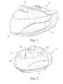
- FIG. 1schematically illustrates a humidifier according to one sample embodiment of the present invention
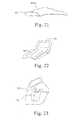
- FIG. 2schematically illustrates a water container of the humidifier of FIG. 1 ;
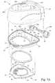
- FIG. 3Aschematically illustrates an exploded assembly view of the cleanable water container of FIG. 2 ;
- FIG. 3Bschematically illustrate a bottom perspective view of a variant of a base plate usable in the assembly of FIG. 3A ;
- FIG. 3Cschematically illustrates a side elevation view of the cleanable water container of the humidifier of FIG. 1 ;
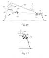
- FIG. 3Dschematically illustrates a pivot hinge usable with the water container of FIGS. 3A-3C ;
- FIG. 4schematically illustrates a rear elevation view of the cleanable water container of FIGS. 2 and 3 A- 3 D;
- FIGS. 5 and 6schematically illustrate a humidifier tub according to another sample embodiment of the present invention
- FIG. 7schematically illustrates a humidifier tub according to another sample embodiment of the invention.
- FIG. 8schematically illustrates a humidifier tub according to another sample embodiment of the present invention.
- FIG. 9schematically illustrates a humidifier tub according to another sample embodiment of the present invention.
- FIG. 10schematically illustrates a humidifier tub according to another sample embodiment of the present invention.
- FIGS. 11 and 12schematically illustrate a humidifier tub according to another sample embodiment of the present invention and FIG. 12A illustrates an additional variant;
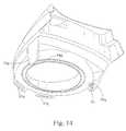
- FIGS. 13 and 14schematically illustrate a humidifier tub according to another sample embodiment of the present invention.
- FIGS. 15 and 16schematically illustrate a humidifier tub according to another sample embodiment of the present invention.
- FIG. 17schematically illustrates a humidifier tub according to another sample embodiment of the present invention.
- FIGS. 18 and 19schematically illustrate a humidifier tub according to another sample embodiment of the present invention.
- FIGS. 20-23schematically illustrate a humidifier tub according to another sample embodiment of the present invention.
- FIGS. 24-26schematically illustrate a humidifier tub according to another sample embodiment of the present invention.
- FIGS. 27-32schematically illustrate a humidifier tub according to another sample embodiment of the invention.
- FIGS. 33 and 34schematically illustrate a humidifier and humidifier tub according to another sample embodiment of the invention.
- FIGS. 35 and 36schematically illustrate a humidifier tub according to another sample embodiment of the invention.
- FIGS. 37 and 38schematically illustrate a humidifier tub according to another sample embodiment of the invention.
- FIG. 39schematically illustrates a humidifier and humidifier tub according to another sample embodiment of the invention.
- FIG. 40schematically illustrates a humidifier according to another sample embodiment of the invention.
- airwill be taken to include breathable gases, for example air with supplemental oxygen. It is also acknowledged that the blowers described herein may be designed to pump fluids other than air.
- a humidifier 10includes a humidifier control base or cradle 12 and a lid 14 hinged to the cradle 12 .
- the hinged lid 14includes an air outlet pipe 16 which is configured for connection to a hose to deliver a supply of pressurized, breathable gas to a patient via a patient interface, such as a mask.
- the humidifier 10includes a water container 20 which is configured to store a supply of water used to humidify the supply of breathable gas.
- the water container 20is configured to be inserted, or “dropped,” into the cradle 12 .
- the hinged lid 14is pivotable to an open position (not shown) for insertion of the water container 20 and pivotable to the closed position shown in FIG.
- the cradle 12facilitates the correct assembly of the humidifier 10 with a flow generator.
- the cradle 12may include a heating element or plate to heat water within the container 20 . Upon insertion of the water container 20 into the cradle 12 , the heating element contacts a base plate of the water container 20 .
- the lid 14When operating with a hose attached, the lid 14 may be snapped down to create an airtight path, for example using a seal or seals.
- the lidWhen the humidifier needs refilling, cleaning, and/or maintenance, the lid may be raised, with the hose still attached, so that the water container is easily accessible.
- the seal, or seals, of the lid 14also forms a part of a spill back protection and spitting requirements that protect both the patient and a flow generator.
- the humidifieris designed to work in a hot and/or humid environment and may be formed of a material that is durable and safe for the patient.
- the humidifieris configured to be connected to a flow generator.
- the humidifiermay be connected to a flow generator in a manner similar to that disclosed in WO 2004/112873 A1, the entire contents of which are incorporated by reference herein.
- the water container 20includes a tub 22 and a tub lid 24 .
- the tub lid 24includes an air inlet aperture 24 a that communicates with an air outlet aperture of the flow generator when the humidifier 10 is connected to the flow generator.
- the tub lid 24also includes a U-shaped air passage 24 b and a humidified air outlet 24 c .
- the humidified air outlet 24 ccommunicates with the air outlet pipe 16 when the hinged lid 14 is in the position shown in FIG. 1 to deliver humidified air to the delivery hose.
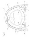
- the tub 22includes a base plate 26 and a tub base 30 .
- the base plate 26may be formed by stamping, for example, a stainless steel plate.
- a stamped ring 27may be formed on the base plate 26 to provide structural rigidity to the base plate 26 so as to provide a flat surface 29 .
- the base plate 26is also formed with alignment tabs 25 and latch tabs 21 .
- a face seal 28is provided between the base plate 26 and the tub base 30 .
- the base plate 26is attached to the tub base 30 , with the face seal 28 therebetween, by inserting the alignment tabs 25 into alignment slots 31 formed in the tub base 30 .
- the portion of the tub base 30 defining the alignment slots 31may act as feet for the tub 22 to keep the tub 20 level when filling.
- the alignment slots 31may be spaced, for example, about 5 mm-15 mm apart, for example about 10 mm.
- the alignment slots 31are asymmetrical to ensure correct placement of the base plate 26 .
- An overcenter latch 38is connected to the tub base 30 by pivot hinges 36 ( FIG. 3D ) and the tub 22 is sealed by pivoting the overcenter latch 38 so that latches 39 catch to engage the latch tabs 21 of the base plate 26 to provide a substantially waterproof sealed connection between the tube base 30 and the base plate 26 .
- the latches 39catch to engage the latch tabs 21 when the overcenter latch 38 is in the engaged position (see FIG. 4 ) to bias the base plate 26 towards the tub base 30 .
- the face seal 28is compressed between the base plate 26 and the tub base 30 by the overcenter latch 38 to provide the substantially waterproof seal.
- the overcenter latch 38may include a textured surface 37 to improve a user's grip on the overcenter latch 38 to permit the overcenter latch 38 to be moved between the engaged and disengaged positions.
- the tub base 30includes a bottom peripheral edge 34 which includes a rim 35 that defines an opening 32 in the tub base 30 .
- the face seal 28has a shape generally corresponding to the bottom peripheral edge 34 of the tub base 30 and the face seal 28 has a width that is sufficient to permit some misalignment between the tub base 30 and the base plate 26 while still maintaining the substantially waterproof seal.
- the bottom peripheral edge 34serves to conceal the edges of the base plate 26 , loosely retain the seal 28 during connection of the tub base 30 to the base plate 26 , and protect the seal 28 from the edges of the base plate 26 during the connection.
- the connection of the latch catches 39 and the latch tabs 21 and the insertion of the alignment tabs 25 into the alignment slots 31define a generally triangular compression region for the face seal 28 , which may be, for example, an O-ring.
- the seal 28may have a generally D-shaped configuration. It should be appreciated, however, that the seal 28 may have another shape, for example an oval shape.
- the base plate 26may also comprise raised edges 23 between the latch tabs 21 and between the latch tabs 21 and the alignment tabs 25 .
- the raised edges 23add stiffness to the base plate 26 to permit the base plate 26 to resist bending under the stresses induced by the pressure of compressing the seal 28 .
- the stamped ring 27acts to isolate the contact surface of the base plate 26 from the installation forces and enable the seal pressing process to maintain a flat region. In a variant shown in FIG. 3B , the stamped ring 27 may be formed to match the shape of the seal 28 .
- the tub base 30may include one or more ribs 37 a provided around a portion of the perimeter of the opening 32 to stiffen the portion of the tub base 30 that will experience high connection forces.
- the rear portion of the tub base 30will experience high connection forces when the overcenter latch 38 is connected to the latch tabs 21 .
- the rear corners of the tub base 30will experience the highest connection forces as the latch catches 39 are connected to the tub base 30 at these locations.
- the rib 37 aact to prevent deflection of the rear portion of the tub base 30 .
- a central gap 37may be provided in the rib 37 a to enable water to drain onto the base plate 26 and ensure that all of the water in the tub 22 is usable.
- the pivot hinges 36are secured to the tub base 30 by pivots 36 b of the pivot hinge 36 .
- the rear of the tub base 30may include four protrusions having holes in each protrusion to accept the pivots 36 b of the pivot hinges 36 .
- the latch catches 39include holes or apertures 39 a ( FIG. 3A ) configured to receive respective pivots 36 a of the pivot hinge 36 .
- the overcenter latch 38forms a part of the user interface for the humidifier tub.
- the overcenter latch 38provides the interfaces for opening and closing the overcenter latch 38 and it interfaces with the base plate 26 to produce the compression force on the face seal 28 .
- the tub base 30 amay include a plurality of locking tabs 40 a - 40 d .
- the base plate 26 ais inserted over the opening 32 a in the tub base 30 a as shown by the arrows in FIG. 5 . It should also be appreciated that the base plate 26 a may be inserted over the opening in a direction perpendicular to the direction shown by the arrows.
- the locking tabs 40 a - 40 dare resilient and are received in locking slots 42 a - 42 d provided in the base plate 26 a in a snap-in manner.
- a groove 44surrounds the periphery of the opening 32 a in the tub base for receipt of a seal 46 , such as an O-ring.
- the tub base 30 amay also include fastener fittings 41 for receipt of fasteners 48 .
- the fasteners 48may be any releasable fastener.
- the base plate 26 bmay be releasably secured to the tub base 30 b by tabs 33 formed on the tub base 30 b and snap rings 50 .
- the base plate 26 bis placed over the opening 32 b in the tub base 30 b in contact with the seal 46 b .
- the snap rings 50are then placed over the base plate 26 b and in engagement with the tabs 33 to secure the base plate 26 b between the snap rings 50 and the seal 46 b .
- the tabs 33are resiliently deformed by insertion of the snap rings 50 so that the snap rings 50 are secured in the position shown in FIG. 7 .
- the base plate 26 cmay be secured to the tub base 30 c by tabs 33 c and a seal 46 c .
- the seal 46 cmay be secured to the tub base 30 c so as to secure the base plate 26 c between the seal 46 c and the tabs 33 c.
- the base plate 26 dmay be secured to the tub base 30 d by tabs 33 d .
- a groove 44 dis provided in the tub base 30 d and the seal (e.g., O-ring) 46 d is provided in the groove 44 d to seal the connection between the base plate 26 d and the tub base 30 d.
- the tub base 30 eincludes a groove 44 e to accommodate a seal 46 e , such as an O-ring.
- Alignment tabs 25 e of the base plate 26 eare inserted into alignment slots 31 e in the tub base 30 e and the opposite end of the base plate 26 e is then pivoted toward the tub base 30 e .
- An overcenter latch 38 econnected to the tub base 30 e by a pivot hinge 36 e . After the alignment tabs 25 e of the base plate 26 e are inserted into the alignment slots 31 e , the opposite end of the base plate 26 e is pivoted toward the tub base 30 e .
- a first end of the overcenter latch 38 eis pivoted into engagement with opposite end of the base plate 26 e and the second end of the overcenter latch 38 e is then pivoted into the assembled condition such that a pin 70 of the pivot hinge 36 e is placed in a notch 72 in the tub base 30 e.
- the tub base 30 fincludes a groove 44 f for accommodating a seal 46 f .
- Tabs 52are provided on the tub base 30 f and the base plate 26 f is assembled to the tub base 30 f by inserting the base plate 26 f to the tube base 30 f in the direction shown by the arrows in FIG. 11 .
- the tabs 52are resilient and the base plate 26 f causes an elastic displacement of the tabs 52 upon insertion.
- the displaced tabs 52remain somewhat displaced upon full insertion of the base plate 26 f to bias the base plate 26 f in contact with the seal 46 f .
- the tabs 52may include tamper evident projections.
- the tamper evident projectionsprovide evidence of tampering with the base plate 26 f in a situation in which the base plate 26 f is designed to be removed only by technician.
- the tabshave a slot 96 with a fragile rib 98 which would crush if tampered with.
- alignment tabs 25 g of the base plate 26 gare inserted into alignment slots 31 g in the tub base 30 g .
- the opposite end of the base plate 26 gis then pivoted toward the tub base 30 g in the direction shown by the arrow in FIG. 13 .
- the base plate 26 gis pivoted into connection with a seal 46 g which is accommodated in a recess 44 g in the tub base 30 g .
- Resilient tabs 52 gare provided for securing the base plate 26 g to the tub base 30 g .
- the tabs 52 ginclude textured finger grips 54 .
- the base plate 26 his attached to the tub base 30 h in the direction shown by the arrow 1 A then 2 A in FIG. 16 . Lips 56 on the tub base 30 h receive the inserted end of the base plate 26 h . As shown in FIG. 16 , the base plate 26 h is then pivoted into engagement with a seal 46 h accommodated in groove 44 h of the tub base 30 h .
- the base plate 26 hincludes an inclined second end 58 which is pivoted past resilient tabs 52 h which include finger grips 54 h .
- the second end 58 of the base plate 26 hmay include a textured surface 23 to improve the user's grip on the base plate 26 h .
- a depression 60is formed into the tub base 30 h to facilitate insertion of a user's finger upon initial displacement of the base plate 26 h to the disassembled position and to permit easier removal of the base plate 26 h from the tub base 30 h .
- the base plate 26 hmay be removed in the direction opposite to the arrow shown in FIG. 15 .
- a seal 62is provided between the base plate 26 j and the tub base 30 j .
- the seal 62acts as a spring to bias the base plate 26 j .
- the seal 62may be used in any of the embodiments disclosed herein.
- a base unit 62includes latches 64 around a top perimeter to lock the tub base 30 k into engagement with the seal 28 k .
- the base plate 26 kis provided between the base unit 62 and the tub base 30 k and the seal 28 k is sandwiched between the base plate 26 k and the tub base 30 k .
- the latches 64secure the contact between the tub base 30 k and the seal 28 k and the contact between the seal 28 k and the base plate 26 k to form a substantially waterproof seal.
- the base unit 62includes an opening 63 .
- a heating element or unit 80such as a ceramic plate, is received in the opening 63 so as to be in contact with the base plate 26 k when the tub is assembled in the base unit 62 .
- Contact between the base plate 26 k and the heating element 80is maintained by the engagement of the latches 64 with the tub base 30 k .
- the latches 64bias the tub base 30 k toward the base plate 26 k thus biasing the base plate 26 k into contact with the heating element 80 .
- the base unit 62may be provided as an integral part of the casing 12 , or separate from the casing.
- a first end of the base plate 26 mis inserted into the tub base 30 m and held in place by lips 56 m .
- the second, opposite end of the base plate 26 mis secured by overcenter cams 68 that engage cam levers 66 provided on the base plate 26 m .
- Each overcenter cam 68is pivotably attached to the tub base 30 m so as to be received in a recess 72 into the tub base 30 m .
- Each overcenter cam 68includes a linkage 70 which engages the cam lever 66 of the base plate 26 m to secure the attachment of the base plate 26 m to the tub base 30 m .
- a surface texture 78such as depressions or projections, may be provided to the overcenter cams 68 that improve a user's grip on the overcenter cams 68 .
- another sample embodiment of the humidifier tub 122may comprise a tub base 130 and a base plate 126 .
- a seal 128( FIG. 26 ) is compressed between a bottom peripheral edge 135 of the tub base 130 and the base plate 126 to form a water tight tub 122 .
- the base plate 126may comprise a stamped ring 127 , which may have a shape corresponding to the seal 128 .
- the base plate 126may be permanently attached to the tub base 130 by tabs, or snaps, 138 formed in the tub base 130 that engage latch tabs 121 on the base plate 126 .
- the tabs, or snaps, 138may be similar to the tabs shown, for example, in FIGS. 11-16 .
- the snaps 138are arranged in sets of two, symmetrical around the center of the tub base 130 , and together with alignment tabs 125 of the base plate 126 that are inserted into alignment slots (not shown) of the tub base 130 , form a generally triangular compression region for the seal 128 .
- the snaps 138grip opposite sides of the latch tabs 121 on the base plate 126 and provide the force for compressing the seal 128 and hold the base plate 126 in position for heat staking.
- the base plate 126comprises apertures 129 in the latch tabs 121 .
- the tub base 130further includes heat stakes 134 that extend through the apertures 129 in the latch tabs 121 , as shown in FIG. 26 .
- the heat stakes 134are passed through apertures in the seal 128 and through the apertures 129 in the base plate 126 .
- the top of the heat stakeis then melted, for example using a heated probe or an ultrasonic horn, to create a blob of plastic.
- the dome 134 a of the heat stake 134assists in holding the base plate 126 in position in a permanent manner that is clearly visible.
- a humidifier tub 222according to another sample embodiment comprises a tub base 230 and a base plate 226 .
- the base plate 226may be formed, for example, as a generally oval stainless steel plate pressed from coil.
- the base plate 226comprises a rib 225 that isolates a contact surface 227 from forces that connect the base plate 226 and the tub base 230 and maintain a flat surface 229 of the base plate.
- a seal 228is provided on the contact surface 227 .
- the base plate 226is connected to the tub base 230 by a snap ring 250 .
- the snap ring 250includes a contact surface 252 .
- the contact surface 252engages the bottom of the seal 228 and the top of the seal 228 is engaged by the contact surface 227 of the base plate 226 .
- the seal 228is compressed between the contact surface 252 of the snap ring 250 and the contact surface 227 of the base plate 226 .
- the snap ring 250is connected to the tub base 230 , with the base plate 226 in between, by the engagement of snaps 254 formed on the inner periphery of the snap ring 250 that engage snaps 234 formed around the periphery of an opening 232 in the tub base 230 .
- the periphery of the opening 232 of the tub base 230also includes a plurality of alignment or guide tabs 235 that are received in a channel 255 in the periphery of the snap ring 250 .
- the alignment or guide tabs 235are received between the snaps 254 of the snap ring 250 when the snap ring 250 is connected to the tub base 230 .
- the alignment or guide tabs 235thus prevent the snap rings 250 from rotating relative to the tub base 230 and disengagement of the snaps 234 , 254 .
- the alignment or guide tabs 235are provided between the snaps 234 around the periphery of the opening 232 .
- eight snaps 234 , 254are shown on the tub base 230 and snap ring 250 , respectively, it should be appreciated that any number of snaps may be provided.
- the opening 232 , the snap ring 250 and the base plate 226may have a shape other than oval, for example circular.
- the snap ring 250retains the base plate 226 to the tub base 230 and prevents the removal of the base plate 226 from the tub base 230 .
- the contact surfaces 252 , 227put pressure on the seal 228 and compress the seal 228 between the snap ring 250 and the base plate 226 .
- the seal 228may be a face oriented O-ring.
- a face oriented O-ringmay be used, as the seal is not relied on to retain the base plate 226 , which eliminates the effect of friction on the installation of the base plate 226 and retention of the base plate 226 .
- the face oriented O-ring 228has a shape generally corresponding to the contact surfaces 227 , 252 and has a width that is sufficient to permit some misalignment between the tub base 230 and the base plate 226 while still maintaining the substantially waterproof seal. This provides a more reliable and robust seal.
- the tub base 230 , the base plate 226 and the snap ring 250are designed to be assembled along a single axis and in one plane. This enables the tub 222 assembly process to be automated, which reduces the cost of manufacture and part-to-part variation.
- a humidifier 10comprises a lid 14 having an outlet 16 configured for connection to a hose or conduit.
- a tub of the humidifiercomprises a tube base 330 , a base plate 326 and a seal 328 provided between the tub base 330 and the base plate 326 .
- the base plate 326comprises a peripheral, e.g. annular, wall 352 that may be folded as shown in FIG. 34 to compress the seal 328 between the base plate 326 and a bottom edge 334 of the tub base 330 .
- the peripheral wall 352may be folded, for example, by bending the peripheral wall 352 , to compress the seal 328 between the bottom edge 334 and the base plate 326 .
- the base plate 326may be made, for example, for metal, such as stainless steel.
- the base plate 426 of the humidifier tubmay comprise an annular wall 451 that includes a curved, or hooked, end 452 that is configured to engage the bottom peripheral edge 434 of the tub base 430 .
- the bottom peripheral edge 434may include a groove, or channel, 435 configured to accommodate a seal 428 , e.g. an O-ring, that is compressed between the base plate 426 and the tub base 430 when the curved end 452 of the base plate 426 engages the bottom peripheral edge 434 of the tub base 430 .
- the base plate 526 of the humidifier tubmay comprise an annular wall 551 having a plurality of resilient tabs 552 formed therein.
- the resilient tabs 552are configured to engage the bottom peripheral edge 534 of the tub base 530 to compress a seal 528 , e.g. an O-ring, between the base plate 526 and the tub base 530 .
- the bottom peripheral edge 534 of the tub base 530may comprise a groove, or channel, 535 to accommodate the seal 528 .
- a humidifier 10may comprise a lid 14 having an outlet 16 configured for connection to a hose or conduit.
- the humidifiermay also comprise a water container comprising a tub including a tub lid 24 and a tub.
- the tubcomprises a tube base 630 and a base plate 626 .
- the tub base 630may comprise an opening 632 surrounded by a bottom peripheral edge 634 .
- the base plate 626is configured to cover the opening 632 and a seal 628 is provided to seal the connection of the base plate 626 to the tub base 630 .
- the tub basecomprises heat stakes 635 that are received in apertures 626 a , 628 a in the base plate 626 and seal 628 , respectively. The ends of the heat stakes 635 are melted, for example by a heated probe or ultrasonically, to form a dome portion similar to the manner described above to permanently connect the base plate 626 to the tube base 630 .
- a cross beam channel 700is configured for insertion into an inlet 24 a of the tub lid 24 .
- the cross beam channelincludes flexible tabs that permit insertion of the cross beam channel 700 into the inlet 24 a , but prevent removal of the cross beam channel 700 after insertion.
- the cross beam channelalso comprises a curved end 702 .
- the curved end 702has the dual function of guiding the inlet air over the surface of the water, and to provide spill back protection.
- the base plate of the embodiments of the present inventionmay be formed of a material that provides good heat conduction, for example metal.
- the base platemay be formed, for example, of stainless steel.
- the base plateis configured to be in contact with a heating device, such as a ceramic heating pad or plate, to increase the amount of water vapor in the supplied air.
- a stainless steel base platetransfers more heat to the water in the tub. Increasing the heat transfer from the base plate to the water in the container by using a stainless steel plate also reduces the energy consumption of the humidifier. Transferring more heat to the water in the tub also allows for an increase in the capacity of the tub while maintaining the required level of humidification.
- the use of a stamped stainless plate for the base platealso reduces the cost of the humidifier as it is less expensive to provide a stamped plate than a machined plate.
- the tub basemay be formed of a plastic material.
- the tub according to the present inventionmay also be removed from the humidifier and easily cleaned, for example by placing the tub in a dishwasher.
- sealsthat are separate from the tub base and the base plate
- the sealmay be formed so as to be integral with the tub base or the base plate, for example by overmolding the seal with the tub base.
Landscapes
- Health & Medical Sciences (AREA)
- Emergency Medicine (AREA)
- Pulmonology (AREA)
- Engineering & Computer Science (AREA)
- Anesthesiology (AREA)
- Biomedical Technology (AREA)
- Heart & Thoracic Surgery (AREA)
- Hematology (AREA)
- Life Sciences & Earth Sciences (AREA)
- Animal Behavior & Ethology (AREA)
- General Health & Medical Sciences (AREA)
- Public Health (AREA)
- Veterinary Medicine (AREA)
- Air Humidification (AREA)
Abstract
Description
Claims (39)
Priority Applications (4)
| Application Number | Priority Date | Filing Date | Title |
|---|---|---|---|
| US13/733,159US8789525B2 (en) | 2007-06-07 | 2013-01-03 | Tub for humidifier |
| US14/304,448US10478585B2 (en) | 2007-06-07 | 2014-06-13 | Tub for humidifier |
| US16/656,739US12011545B2 (en) | 2007-06-07 | 2019-10-18 | Tub for humidifier |
| US18/663,785US20240293639A1 (en) | 2007-06-07 | 2024-05-14 | Tub for humidifier |
Applications Claiming Priority (4)
| Application Number | Priority Date | Filing Date | Title |
|---|---|---|---|
| US94256707P | 2007-06-07 | 2007-06-07 | |
| US3951408P | 2008-03-26 | 2008-03-26 | |
| US12/134,310US8365726B2 (en) | 2007-06-07 | 2008-06-06 | Tub for humidifier |
| US13/733,159US8789525B2 (en) | 2007-06-07 | 2013-01-03 | Tub for humidifier |
Related Parent Applications (1)
| Application Number | Title | Priority Date | Filing Date |
|---|---|---|---|
| US12/134,310ContinuationUS8365726B2 (en) | 2007-06-07 | 2008-06-06 | Tub for humidifier |
Related Child Applications (1)
| Application Number | Title | Priority Date | Filing Date |
|---|---|---|---|
| US14/304,448ContinuationUS10478585B2 (en) | 2007-06-07 | 2014-06-13 | Tub for humidifier |
Publications (2)
| Publication Number | Publication Date |
|---|---|
| US20130118492A1 US20130118492A1 (en) | 2013-05-16 |
| US8789525B2true US8789525B2 (en) | 2014-07-29 |
Family
ID=40094716
Family Applications (5)
| Application Number | Title | Priority Date | Filing Date |
|---|---|---|---|
| US12/134,310Active2031-04-11US8365726B2 (en) | 2007-06-07 | 2008-06-06 | Tub for humidifier |
| US13/733,159ActiveUS8789525B2 (en) | 2007-06-07 | 2013-01-03 | Tub for humidifier |
| US14/304,448Active2031-04-23US10478585B2 (en) | 2007-06-07 | 2014-06-13 | Tub for humidifier |
| US16/656,739Active2031-11-26US12011545B2 (en) | 2007-06-07 | 2019-10-18 | Tub for humidifier |
| US18/663,785PendingUS20240293639A1 (en) | 2007-06-07 | 2024-05-14 | Tub for humidifier |
Family Applications Before (1)
| Application Number | Title | Priority Date | Filing Date |
|---|---|---|---|
| US12/134,310Active2031-04-11US8365726B2 (en) | 2007-06-07 | 2008-06-06 | Tub for humidifier |
Family Applications After (3)
| Application Number | Title | Priority Date | Filing Date |
|---|---|---|---|
| US14/304,448Active2031-04-23US10478585B2 (en) | 2007-06-07 | 2014-06-13 | Tub for humidifier |
| US16/656,739Active2031-11-26US12011545B2 (en) | 2007-06-07 | 2019-10-18 | Tub for humidifier |
| US18/663,785PendingUS20240293639A1 (en) | 2007-06-07 | 2024-05-14 | Tub for humidifier |
Country Status (1)
| Country | Link |
|---|---|
| US (5) | US8365726B2 (en) |
Cited By (7)
| Publication number | Priority date | Publication date | Assignee | Title |
|---|---|---|---|---|
| USD828917S1 (en)* | 2015-09-25 | 2018-09-18 | Fisher & Paykel Healthcare Limited | Vent diffuser |
| USD849931S1 (en) | 2015-09-25 | 2019-05-28 | Fisher & Paykel Healthcare Limited | Face mask cushion |
| USD876616S1 (en) | 2015-09-25 | 2020-02-25 | Fisher & Paykel Healthcare Limited | Headgear |
| USD958969S1 (en) | 2015-09-25 | 2022-07-26 | Fisher & Paykel Healthcare Limited | Face mask frame |
| US11400247B2 (en) | 2016-12-22 | 2022-08-02 | Fisher & Paykel Healthcare Limited | Breathing assistance apparatus |
| US20220273905A1 (en)* | 2013-03-15 | 2022-09-01 | ResMed Pty Ltd | Humidifier reservoir |
| US12011545B2 (en) | 2007-06-07 | 2024-06-18 | ResMed Pty Ltd | Tub for humidifier |
Families Citing this family (49)
| Publication number | Priority date | Publication date | Assignee | Title |
|---|---|---|---|---|
| DE10139881B4 (en) | 2001-08-20 | 2017-06-08 | Resmed R&D Germany Gmbh | Apparatus for supplying a breathing gas and method for controlling the same |
| AU2003903139A0 (en) | 2003-06-20 | 2003-07-03 | Resmed Limited | Breathable gas apparatus with humidifier |
| FR2875138B1 (en) | 2004-09-15 | 2008-07-11 | Mallinckrodt Dev France Sa | CONTROL METHOD FOR A HEATING HUMIDIFIER |
| US8739780B2 (en) | 2005-08-15 | 2014-06-03 | Resmed Limited | Low cost CPAP flow generator and humidifier assembly |
| CN102133447B (en) | 2005-08-15 | 2015-01-07 | 瑞思迈有限公司 | Humidifier and/or flow generator for CPAP device |
| US9802022B2 (en) | 2008-03-06 | 2017-10-31 | Resmed Limited | Humidification of respiratory gases |
| EP2337604B1 (en)* | 2008-09-17 | 2018-01-24 | ResMed Limited | Humidification of respiratory gases |
| WO2010067238A1 (en)* | 2008-12-12 | 2010-06-17 | Koninklijke Philips Electronics, N.V. | Cushion coupling assembly |
| US20100242961A1 (en)* | 2009-03-31 | 2010-09-30 | Nellcor Puritan Bennett Llc | Systems and methods for preventing water damage in a breathing assistance system |
| US20100300446A1 (en)* | 2009-05-26 | 2010-12-02 | Nellcor Puritan Bennett Llc | Systems and methods for protecting components of a breathing assistance system |
| CN102481431B (en)* | 2009-06-05 | 2015-09-16 | 费雪派克医疗保健有限公司 | The heater support of humidifier |
| AU2010206053B2 (en) | 2009-07-31 | 2014-08-07 | ResMed Pty Ltd | Wire Heated Tube with Temperature Control System, Tube Type Detection, and Active Over Temperature Protection for Humidifier for Respiratory Apparatus |
| US9737682B2 (en)* | 2009-09-17 | 2017-08-22 | Resmed Limited | Humidification of respiratory gases |
| USD671206S1 (en)* | 2009-12-04 | 2012-11-20 | Vapotherm, Inc. | Respiratory therapy system |
| US8844533B2 (en) | 2011-06-22 | 2014-09-30 | Breathe Technologies, Inc. | Ventilation mask with integrated piloted exhalation valve |
| US9616194B2 (en) | 2011-06-22 | 2017-04-11 | Breathe Technologies, Inc. | Ventilation mask with integrated piloted exhalation valve and method of ventilating a patient using the same |
| US9038634B2 (en) | 2011-06-22 | 2015-05-26 | Breathe Technologies, Inc. | Ventilation mask with integrated piloted exhalation valve |
| ITRE20110054A1 (en)* | 2011-07-19 | 2013-01-20 | Starmed S P A | OPENABLE HELMET FOR NON-INVASIVE VENTILATION OF PATIENTS |
| ITRE20120018A1 (en)* | 2012-03-13 | 2013-09-14 | Starmed S P A | HELMET FOR NON-INVASIVE VENTILATION OF PATIENTS |
| EP3738638A1 (en) | 2012-03-15 | 2020-11-18 | Fisher & Paykel Healthcare Limited | Respiratory gas humidification system |
| GB2575894A (en) | 2012-04-27 | 2020-01-29 | Fisher & Paykel Healthcare Ltd | Usability features for respiratory humidification system |
| SG10201701548TA (en)* | 2012-09-07 | 2017-03-30 | Fisher & Paykel Healthcare Ltd | Humidification chamber for a respiratory assistance apparatus |
| CA2885362C (en) | 2012-09-25 | 2022-12-06 | Fisher & Paykel Healthcare Limited | Lid construction for breathing apparatus |
| NZ710078A (en) | 2013-02-01 | 2017-01-27 | Resmed Ltd | Wire heated tube with temperature control system for humidifier for respiratory apparatus |
| US9878121B2 (en) | 2013-03-13 | 2018-01-30 | Breathe Technologies, Inc. | Ventilation mask with heat and moisture exchange device |
| US9861778B2 (en) | 2013-03-15 | 2018-01-09 | Resmed Limited | Humidifier reservoir |
| US10052250B2 (en) | 2013-05-07 | 2018-08-21 | Intersurgical S.P.A. | Openable helmet of non-invasive ventilation of patients |
| GB2584026B (en) | 2013-09-13 | 2021-03-17 | Fisher & Paykel Healthcare Ltd | A heater base for supplying humidified gases to a patient |
| JP6663850B2 (en) | 2013-09-13 | 2020-03-13 | フィッシャー アンド ペイケル ヘルスケア リミテッド | Humidification system connection |
| CN106029147B (en) | 2013-12-20 | 2020-01-21 | 费雪派克医疗保健有限公司 | Humidification system connection |
| US10449319B2 (en) | 2014-02-07 | 2019-10-22 | Fisher & Paykel Healthcare Limited | Respiratory humidification system |
| TWM481735U (en)* | 2014-03-14 | 2014-07-11 | Lead Data Inc | Humidifier and breathing apparatus using the same |
| US11173272B2 (en) | 2014-05-02 | 2021-11-16 | Fisher & Paykel Healthcare Limited | Gas humidification arrangement |
| CN110124174A (en) | 2014-05-13 | 2019-08-16 | 费雪派克医疗保健有限公司 | Availability aspect for breathing humidification system |
| CN106535971B (en) | 2014-06-03 | 2020-12-04 | 费雪派克医疗保健有限公司 | Flow mixers for respiratory therapy systems |
| WO2016080847A1 (en) | 2014-11-17 | 2016-05-26 | Fisher & Paykel Healthcare Limited | Humidification of respiratory gases |
| CN104368072B (en)* | 2014-11-28 | 2016-11-23 | 江苏鱼跃信息系统有限公司 | There is the little area water tank of circulative convection structure |
| WO2016089224A1 (en)* | 2014-12-03 | 2016-06-09 | Fisher & Paykel Healthcare Limited | Respiratory gas therapy |
| USD857189S1 (en)* | 2016-03-11 | 2019-08-20 | ResMed Pty Ltd | Battery pack for an air delivery module |
| WO2017192051A1 (en) | 2016-05-02 | 2017-11-09 | Fisher & Paykel Healthcare Limited | Humidification chamber and chamber seal for a respiratory assistance apparatus |
| EP3551978B1 (en) | 2016-12-07 | 2022-01-26 | Fisher&Paykel Healthcare Limited | Sensing arrangements for medical devices |
| EP3793653B1 (en) | 2018-05-14 | 2023-10-25 | Covidien LP | Systems and methods for ventilation humidification |
| US12268816B2 (en) | 2018-11-05 | 2025-04-08 | Fisher & Paykel Healthcare Limited | Breathing assistance apparatus |
| WO2020128829A1 (en)* | 2018-12-18 | 2020-06-25 | ResMed Pty Ltd | Humidifier reservoir |
| CN116637264A (en) | 2019-04-17 | 2023-08-25 | 瑞思迈私人有限公司 | CPAP system |
| JP2022534855A (en)* | 2019-06-06 | 2022-08-04 | ヴィンセント メディカル(ドングアン)マニュファクチャリング シーオー.,エルティーディー. | improved heater plate |
| US12427282B2 (en) | 2020-09-09 | 2025-09-30 | Covidien Lp | Systems and methods for active humidification in ventilatory support |
| CN112178979A (en)* | 2020-09-23 | 2021-01-05 | 刘文山 | Air source heat pump energy-saving device convenient to install for kitchen |
| US20250235382A1 (en)* | 2024-01-18 | 2025-07-24 | Dcstar Inc | Liquid storage container for a humidifier |
Citations (278)
| Publication number | Priority date | Publication date | Assignee | Title |
|---|---|---|---|---|
| US1475289A (en) | 1922-01-16 | 1923-11-27 | Diescher & Sons S | Expansion joint |
| US1974843A (en) | 1932-11-05 | 1934-09-25 | Scanlan Morris Company | Gas humidifying device |
| USRE19826E (en) | 1936-01-21 | aisenstein | ||
| US2220669A (en) | 1936-06-26 | 1940-11-05 | Allen Sherman Hoff Co | Impeller for centrifugal pumps |
| US2500404A (en) | 1946-12-13 | 1950-03-14 | Ambory Electric & Mfg Company | Drain cleaner |
| US2872560A (en) | 1957-11-01 | 1959-02-03 | Glen A Bowles | Coffee percolator |
| US2945619A (en) | 1954-09-21 | 1960-07-19 | Mclure Carl Ballard | Stage expansion reaction turbines |
| US2998198A (en) | 1959-10-07 | 1961-08-29 | Int Nickel Co | Variable size flow nozzle |
| US3090380A (en) | 1961-04-13 | 1963-05-21 | John F Dold | Resuscitation device |
| US3171353A (en) | 1962-02-27 | 1965-03-02 | Kenton D Mcmahan | Centrifugal fluid pump |
| US3275344A (en) | 1965-02-19 | 1966-09-27 | Gen Electric | Misalignment compensating coupling |
| US3316910A (en) | 1963-12-20 | 1967-05-02 | Thomas A Davis | Method and apparatus for dissolving renal calculi |
| US3388705A (en) | 1965-04-08 | 1968-06-18 | Foregger Company Inc | Universal endotracheal tube coupling or adaptor |
| US3584401A (en) | 1969-07-01 | 1971-06-15 | Burtek Inc | Educational display device and method |
| US3612710A (en) | 1970-04-30 | 1971-10-12 | Carrier Corp | Centrifugal refrigerant gas compressor |
| US3620638A (en) | 1970-08-24 | 1971-11-16 | J Arthur Kaye | Liquid propulsion device |
| US3638926A (en) | 1967-09-27 | 1972-02-01 | Alfred W Melville | Humidification |
| US3659604A (en) | 1970-03-30 | 1972-05-02 | Fisher & Paykel | Humidifying means |
| US3690317A (en) | 1970-10-29 | 1972-09-12 | Bendix Corp | Sonic nebulizer |
| US3804280A (en) | 1971-07-27 | 1974-04-16 | Respiratory Care | Multi-use inhalation therapy apparatus |
| US3806102A (en) | 1972-06-20 | 1974-04-23 | Arirco Inc | Medical humidifier |
| US3864440A (en) | 1972-01-21 | 1975-02-04 | Respiratory Care | Humidifier and heater for delivered gas |
| US3954920A (en) | 1973-09-04 | 1976-05-04 | Parkland International Inc. | Gas humidification system |
| US4000341A (en) | 1975-05-23 | 1976-12-28 | Minnesota Mining And Manufacturing Company | Autoclavable, corrugated, respiratory care tubing |
| FR2323436A1 (en) | 1975-09-10 | 1977-04-08 | Grant Graham | RESPIRATORY AIR HUMIDIFIER FOR MEDICAL USE |
| US4037994A (en) | 1975-03-31 | 1977-07-26 | Bird F M | Pressure unloading valve device for compressor |
| US4049233A (en) | 1975-10-03 | 1977-09-20 | Stal Refrigeration Ab | Device for establishing and breaking a fluid communication |
| US4051205A (en) | 1972-09-13 | 1977-09-27 | Graham Cameron Grant | Apparatus for saturated gas delivery |
| US4105372A (en) | 1975-01-31 | 1978-08-08 | Hitachi, Ltd. | Fluid rotary machine |
| US4124046A (en) | 1975-10-16 | 1978-11-07 | Stal Refrigeration Ab | Connecting device for intermittent air flow |
| US4152379A (en) | 1977-05-26 | 1979-05-01 | Airco, Inc. | Anesthesia humidifier |
| US4164645A (en) | 1977-10-14 | 1979-08-14 | P. Ferrero C. S.p.A. | Device for heating liquids contained in sealed plastics containers |
| US4165456A (en) | 1977-10-14 | 1979-08-21 | P. Ferrero & C. S.P.A. | Device for heating to consumption temperature a liquid commestible product sealed in a disposable container |
| US4171190A (en) | 1976-11-08 | 1979-10-16 | Molded Products Company | Blower motor mounting assembly |
| US4201737A (en) | 1977-07-15 | 1980-05-06 | Airco, Inc. | Nebulizing apparatus |
| US4203027A (en) | 1977-03-07 | 1980-05-13 | Fisher & Paykel Limited | Electrically heated humidifying apparatus |
| US4222971A (en) | 1978-11-14 | 1980-09-16 | Eilert Richard L | Humidifier liner |
| US4229142A (en) | 1977-11-10 | 1980-10-21 | Le Materiel Telephonique | One-piece pumping device with ambivalent operation |
| US4237080A (en) | 1979-01-11 | 1980-12-02 | Skuttle Mfg. Co. | Humidifier assemblies |
| US4243396A (en) | 1979-04-16 | 1981-01-06 | Becton, Dickinson And Company | Humidifier separator |
| DE3005094A1 (en) | 1980-02-12 | 1981-08-20 | Klein, Schanzlin & Becker Ag, 6710 Frankenthal | CENTRIFUGAL PUMP WITH OPEN DIPPLE SPIRAL HOUSING |
| US4286815A (en) | 1978-06-15 | 1981-09-01 | Bausch & Lomb Incorporated | Lens insertion and removal device |
| US4336798A (en) | 1980-10-06 | 1982-06-29 | Anthony V. Beran | Medical corrugated respiratory tube |
| US4463248A (en)* | 1981-11-09 | 1984-07-31 | Kaz Manufacturing Co., Inc. | Non-spitting noiseless electric steam vaporizer |
| US4496132A (en) | 1981-08-27 | 1985-01-29 | Zvi Weingarten | Sleeve valve with integral control chamber |
| US4523896A (en) | 1982-06-04 | 1985-06-18 | Creusot-Loire | Centrifugal compressor |
| US4532088A (en) | 1983-05-19 | 1985-07-30 | Inspiron Corporation | Heated respiratory therapy humidifier |
| US4557261A (en) | 1980-12-20 | 1985-12-10 | Ruegheimer Erich | Connection system for fluid lines having telescoping connecting elements, in particular for respirators or anesthetic units |
| GB2116434B (en) | 1982-02-23 | 1985-12-11 | Engstrom Medical Ab | A device for connecting a respirator or anesthesia machine to a patient |
| US4575128A (en) | 1983-02-09 | 1986-03-11 | Ab Volvo | Seal, especially for a coupling between an air intake on a tilting truck cab and a pipe securely mounted on the chassis |
| US4576616A (en) | 1982-07-27 | 1986-03-18 | Proto-Med. Inc. | Method and apparatus for concentrating oxygen |
| US4621632A (en) | 1984-11-01 | 1986-11-11 | Bear Medical Systems, Inc. | Humidifier system |
| EP0201985A1 (en) | 1985-04-04 | 1986-11-20 | The BOC Group plc | Inhalation apparatus |
| GB2177006A (en) | 1985-06-21 | 1987-01-14 | Kendall & Co | Feeding system |
| DE3623162A1 (en) | 1985-07-15 | 1987-01-22 | Carus Carl Gustav | Ventilator with universal valve combination for neonatology |
| US4644790A (en) | 1985-04-01 | 1987-02-24 | Sharp Kabushiki Kaisha | Liquid level indicator for humidifier |
| US4657713A (en) | 1983-05-19 | 1987-04-14 | Intertech Resources Inc. | Heated respiratory therapy humidifier |
| US4676237A (en) | 1985-01-29 | 1987-06-30 | Boutade Worldwide Investments Nv | Inhaler device |
| US4714078A (en) | 1984-12-03 | 1987-12-22 | Paluch Bernard R | Insert for heated humidifier used in respiratory therapy |
| GB2192136A (en) | 1986-07-04 | 1988-01-06 | Virotherm Lab Ltd | Humidifiers for inhalers |
| GB2173107B (en) | 1985-04-04 | 1988-06-15 | Boc Group Plc | Improvements in inhalation apparatus |
| DE3642637A1 (en) | 1986-12-13 | 1988-06-23 | Ruetgerswerke Ag | METHOD FOR PRODUCING COMPONENTS |
| US4753758A (en) | 1983-05-19 | 1988-06-28 | Intertech Resources Inc. | Respiratory humidifier |
| EP0274996A2 (en) | 1986-12-31 | 1988-07-20 | ELMED GINEVRI s.r.l. | Constant flow pressure-responsive pulmotor |
| GB2173108B (en) | 1985-04-04 | 1988-10-05 | Boc Group Plc | Improvements in inhalation apparatus |
| US4799287A (en) | 1987-05-04 | 1989-01-24 | Belanger, Inc. | Blower housing construction |
| US4802819A (en) | 1987-09-14 | 1989-02-07 | Mcneil (Ohio) Corporation | Centrifugal pump |
| US4807616A (en) | 1987-07-09 | 1989-02-28 | Carmeli Adahan | Portable ventilator apparatus |
| US4838258A (en) | 1987-10-26 | 1989-06-13 | Gibeck-Dryden Corporation | Gas sampling lumen for breathing system |
| EP0339234A1 (en) | 1988-04-23 | 1989-11-02 | Johannes Klöber | Ventilation hose |
| DE3823242A1 (en) | 1988-07-08 | 1990-02-22 | Lang Volker | Y adapter with integrated water trap and automatic condensate eliminating system for connecting ventilated patients to ventilator tubing systems |
| US4906417A (en) | 1988-02-08 | 1990-03-06 | Associated Mills Inc. | Humidifier |
| US4910384A (en)* | 1988-08-23 | 1990-03-20 | The Kendall Company | Position independent humidifier apparatus |
| US4913140A (en)* | 1987-09-07 | 1990-04-03 | Fisher & Paykel Limited | Float-controlled humidifier |
| US4921642A (en) | 1987-12-03 | 1990-05-01 | Puritan-Bennett Corporation | Humidifier module for use in a gas humidification assembly |
| US4926856A (en) | 1985-06-21 | 1990-05-22 | Hudson Oxygen Therapy Sales Company | Feeding system |
| US4941469A (en) | 1987-11-12 | 1990-07-17 | Carmeli Adahan | Portable ventilator apparatus |
| US4943704A (en) | 1989-02-06 | 1990-07-24 | Ryder International Corporation | Humidifier apparatus |
| US4944310A (en) | 1981-04-24 | 1990-07-31 | Somed Pty. Ltd. | Device for treating snoring sickness |
| US4946348A (en) | 1989-02-14 | 1990-08-07 | Airflow Research & Manufacturing Corporation | Centrifugal fan with airfoil vanes in annular volute envelope |
| US4953546A (en) | 1985-07-16 | 1990-09-04 | Transpirator Technologies, Inc. | Method and apparatus for pulmonary and cariovascular conditioning of the young of large animals |
| US4953897A (en) | 1988-04-23 | 1990-09-04 | Kloeber Johannes | Vent pipe coupling |
| US4973234A (en) | 1989-10-23 | 1990-11-27 | Davidson Textron Inc. | Shell mold mechanism |
| US4993411A (en) | 1990-04-06 | 1991-02-19 | Medway | Ultrasonic oxygen humidifier |
| US5061405A (en) | 1990-02-12 | 1991-10-29 | Emerson Electric Co. | Constant humidity evaporative wicking filter humidifier |
| FR2663547A1 (en) | 1990-06-25 | 1991-12-27 | Taema | Installation for continuous supply of an excess pressure of respiratory gas |
| US5127800A (en) | 1984-03-20 | 1992-07-07 | Baker Hughes Incorporated | Flow-stabilizing volute pump and liner |
| WO1993005451A1 (en) | 1991-09-03 | 1993-03-18 | Geno Svast | Reminder clock |
| DE4244493A1 (en) | 1992-01-18 | 1993-07-22 | Eilentropp Hew Kabel | |
| US5231979A (en) | 1992-02-14 | 1993-08-03 | Puritan-Bennett Corporation | Humidifier for CPAP device |
| US5237987A (en) | 1990-06-07 | 1993-08-24 | Infrasonics, Inc. | Human lung ventilator system |
| US5271391A (en) | 1991-12-20 | 1993-12-21 | Linda Graves | Apparatus for delivering a continuous positive airway pressure to an infant |
| DE9317450U1 (en) | 1993-11-15 | 1994-06-09 | Metrax Gmbh, 78628 Rottweil | Ventilator |
| US5329939A (en) | 1992-12-11 | 1994-07-19 | Cimco, Inc. | Humidifier with liquid level control |
| US5339825A (en) | 1991-04-18 | 1994-08-23 | Clement Clarke International Ltd. | Apparatus to measure and record peak air passage pressure |
| US5349946A (en) | 1992-10-07 | 1994-09-27 | Mccomb R Carter | Microprocessor controlled flow regulated molecular humidifier |
| DE9409231U1 (en) | 1994-06-07 | 1994-11-03 | Madaus Schwarzer Medizintechnik GmbH & Co. KG, 81245 München | Respirator for sleep medicine |
| US5391063A (en) | 1994-04-25 | 1995-02-21 | General Motors Corporation | Magnet assembly for electric fuel pump |
| WO1995015778A1 (en) | 1993-12-07 | 1995-06-15 | Technimeca International Inc. | Anti-gaslock filling device for a liquid receptacle |
| FR2714985A1 (en) | 1994-01-11 | 1995-07-13 | Lenfant Jean Pierre | Storage and recovery of personal secret code for transaction card |
| US5443061A (en) | 1991-03-21 | 1995-08-22 | Taema | Apparatus for providing a breathing gas with an overpressure and process of controlling such apparatus installation |
| US5445143A (en) | 1992-09-23 | 1995-08-29 | Fisher & Paykel Limited | Humidifier with dual float valves |
| US5483616A (en) | 1994-12-21 | 1996-01-09 | Duracraft Corporation | Humidifier tank with improved handle |
| US5482031A (en) | 1991-09-20 | 1996-01-09 | Gibeck Respiration Ab | Arrangement for connecting a patient to a respirator, and the use of a moisture-heat-exchanger in the arrangement |
| GB2293325A (en) | 1994-09-20 | 1996-03-27 | Fisher & Paykel | Humidification chamber for respiratory gases |
| DE4138098C2 (en) | 1991-11-19 | 1996-07-04 | Devilbiss Medizinische Produkt | Device for providing warm humidified breathing gas |
| US5537997A (en) | 1995-01-26 | 1996-07-23 | Respironics, Inc. | Sleep apnea treatment apparatus and passive humidifier for use therewith |
| US5551419A (en) | 1994-12-15 | 1996-09-03 | Devilbiss Health Care, Inc. | Control for CPAP apparatus |
| US5558084A (en) | 1991-10-04 | 1996-09-24 | Fisher & Paykel Limited | Humidifier with delivery tube condensation preventing structure and control |
| US5564415A (en) | 1995-06-07 | 1996-10-15 | Lifecare International, Inc. | Humidifier for a ventilator |
| DE19515739A1 (en) | 1995-05-03 | 1996-11-07 | Holger Krohn | Method and device for generating health-friendly breathing air in nasal positive pressure respirators |
| US5577496A (en) | 1993-04-14 | 1996-11-26 | Mine Safety Appliances Company | Respiratory protective apparatus |
| US5598837A (en) | 1995-06-06 | 1997-02-04 | Respironics, Inc. | Passive humidifier for positive airway pressure devices |
| US5651775A (en) | 1995-07-12 | 1997-07-29 | Walker; Richard Bradley | Medication delivery and monitoring system and methods |
| WO1997032619A1 (en) | 1996-03-08 | 1997-09-12 | Medisize B.V. | Device and process for monitoring the respiration parameters of an artificial respiration system |
| US5682289A (en) | 1991-12-11 | 1997-10-28 | Hewlett-Packard Company | Chassis of a device |
| DE19630466A1 (en) | 1996-07-27 | 1998-02-05 | Nikolaus Netzer | Device for supplying gas for sleep apnea |
| EP0845277A2 (en) | 1996-12-02 | 1998-06-03 | FISHER & PAYKEL LIMITED | Humidifier sleep apnea treatment apparatus |
| US5783117A (en)* | 1997-01-09 | 1998-07-21 | Hunter Fan Company | Evaporative humidifier |
| WO1998031937A1 (en) | 1997-01-17 | 1998-07-23 | ABB Fläkt Oy | High-pressure fan |
| WO1998033433A1 (en) | 1997-01-31 | 1998-08-06 | Respironics Georgia, Inc. | Method and apparatus for treating airway disorders |
| US5794219A (en) | 1996-02-20 | 1998-08-11 | Health Hero Network, Inc. | Method of conducting an on-line auction with bid pooling |
| US5822715A (en) | 1997-01-10 | 1998-10-13 | Health Hero Network | Diabetes management system and method for controlling blood glucose |
| US5828943A (en) | 1994-04-26 | 1998-10-27 | Health Hero Network, Inc. | Modular microprocessor-based diagnostic measurement apparatus and method for psychological conditions |
| US5832448A (en) | 1996-10-16 | 1998-11-03 | Health Hero Network | Multiple patient monitoring system for proactive health management |
| US5848592A (en) | 1995-09-25 | 1998-12-15 | Sibley; Nels B. | Air filter |
| WO1998057691A1 (en) | 1997-06-18 | 1998-12-23 | Resmed Limited | An apparatus for supplying breathable gas |
| DE19752672C1 (en) | 1997-11-28 | 1999-03-04 | Buhler Motor Gmbh | Setting drive housing |
| US5879163A (en) | 1996-06-24 | 1999-03-09 | Health Hero Network, Inc. | On-line health education and feedback system using motivational driver profile coding and automated content fulfillment |
| US5887133A (en) | 1997-01-15 | 1999-03-23 | Health Hero Network | System and method for modifying documents sent over a communications network |
| EP0903160A1 (en) | 1997-09-11 | 1999-03-24 | Siemens-Elema AB | Inspiratory tube |
| WO1999013932A1 (en) | 1997-09-19 | 1999-03-25 | Respironics, Inc. | Medical ventilator |
| US5888053A (en) | 1995-02-10 | 1999-03-30 | Ebara Corporation | Pump having first and second outer casing members |
| US5897493A (en) | 1997-03-28 | 1999-04-27 | Health Hero Network, Inc. | Monitoring system for remotely querying individuals |
| US5899855A (en) | 1992-11-17 | 1999-05-04 | Health Hero Network, Inc. | Modular microprocessor-based health monitoring system |
| DE29817685U1 (en) | 1998-10-05 | 1999-05-06 | Hoffrichter, Helmut, 19057 Schwerin | Coupling device for a respirator with a humidifier |
| WO1999022794A1 (en) | 1997-11-03 | 1999-05-14 | Resmed Limited | Noise damping mounting body for cpap compressor |
| WO1999022793A1 (en) | 1997-11-03 | 1999-05-14 | Resmed Limited | A muffler for an apparatus for supplying breathable gas |
| US5913310A (en) | 1994-05-23 | 1999-06-22 | Health Hero Network, Inc. | Method for diagnosis and treatment of psychological and emotional disorders using a microprocessor-based video game |
| US5916493A (en) | 1997-08-12 | 1999-06-29 | Pegasus Research Corporation | Humidifier system |
| US5918603A (en) | 1994-05-23 | 1999-07-06 | Health Hero Network, Inc. | Method for treating medical conditions using a microprocessor-based video game |
| US5933136A (en) | 1996-12-23 | 1999-08-03 | Health Hero Network, Inc. | Network media access control system for encouraging patient compliance with a treatment plan |
| US5940801A (en) | 1994-04-26 | 1999-08-17 | Health Hero Network, Inc. | Modular microprocessor-based diagnostic measurement apparatus and method for psychological conditions |
| US5943473A (en)* | 1997-05-29 | 1999-08-24 | Levine; Walter | Heated cartridge humidifier |
| DE29909611U1 (en) | 1999-06-02 | 1999-09-02 | Hoffrichter, Helmut, Dipl.-Ing., 19057 Schwerin | Arrangement for a heatable humidifier |
| US5951300A (en) | 1997-03-10 | 1999-09-14 | Health Hero Network | Online system and method for providing composite entertainment and health information |
| US5960403A (en) | 1992-11-17 | 1999-09-28 | Health Hero Network | Health management process control system |
| US5985559A (en) | 1997-04-30 | 1999-11-16 | Health Hero Network | System and method for preventing, diagnosing, and treating genetic and pathogen-caused disease |
| US5997476A (en) | 1997-03-28 | 1999-12-07 | Health Hero Network, Inc. | Networked system for interactive communication and remote monitoring of individuals |
| WO1999064747A1 (en) | 1998-06-11 | 1999-12-16 | Resmed Limited | A housing for a centrifugal impeller |
| USD419658S (en) | 1998-08-28 | 2000-01-25 | Resmed Limited | Humidifier |
| US6023686A (en) | 1996-02-20 | 2000-02-08 | Health Hero Network | Method for conducting an on-line bidding session with bid pooling |
| US6024694A (en) | 1995-09-25 | 2000-02-15 | Hill-Rom, Inc. | Humidifier for a thermal support apparatus |
| US6032119A (en) | 1997-01-16 | 2000-02-29 | Health Hero Network, Inc. | Personalized display of health information |
| US6052511A (en) | 1998-12-18 | 2000-04-18 | Honeywell Inc. | Humidifier with removable water supply tank |
| WO2000021602A1 (en) | 1998-10-13 | 2000-04-20 | Fisher & Paykel Limited | Respiratory humidification chamber |
| WO2000027457A1 (en) | 1998-11-05 | 2000-05-18 | Resmed Ltd. | Fault diagnosis in cpap and nippv devices |
| WO2000032261A1 (en) | 1998-12-04 | 2000-06-08 | Bunnel, Incorporated | Variable flow and pressure ventilation system |
| WO2000038771A1 (en) | 1998-12-23 | 2000-07-06 | Resmed Limited | An apparatus for supplying breathable gas |
| WO2000042324A2 (en) | 1999-01-18 | 2000-07-20 | MAP Medizintechnik für Arzt und Patient GmbH & Co. KG | Blow device |
| EP1023912A2 (en) | 1999-01-30 | 2000-08-02 | GOTTLIEB WEINMANN GERÄTE FÜR MEDIZIN UND ARBEITSSCHUTZ GMBH & CO. | Respiratory device and method for the preparation of a respiratory gas |
| US6101478A (en) | 1997-04-30 | 2000-08-08 | Health Hero Network | Multi-user remote health monitoring system |
| US6109865A (en) | 1997-11-14 | 2000-08-29 | Kioritz Corporation | Portable air-blowing working machine |
| JP2000237316A (en) | 1999-02-17 | 2000-09-05 | Teijin Ltd | Humidifier |
| US6129524A (en) | 1998-12-07 | 2000-10-10 | Turbodyne Systems, Inc. | Motor-driven centrifugal air compressor with axial airflow |
| US6131571A (en) | 1997-04-30 | 2000-10-17 | University Of Florida | Ventilation apparatus and anesthesia delivery system |
| US6135432A (en) | 1995-06-08 | 2000-10-24 | Resmed Limited | Humidifier |
| US6144837A (en) | 1994-11-04 | 2000-11-07 | Health Hero Network, Inc. | Method and apparatus for interactively monitoring a physiological condition and for interactively providing health-related information |
| EP1055431A2 (en) | 1999-05-10 | 2000-11-29 | FISHER & PAYKEL LIMITED | A water chamber |
| US6161095A (en) | 1998-12-16 | 2000-12-12 | Health Hero Network, Inc. | Treatment regimen compliance and efficacy with feedback |
| US6158978A (en) | 1998-08-26 | 2000-12-12 | Cary Products Co., Inc. | Blower housing motor mount adapter and gaskets |
| US6186140B1 (en) | 1997-03-14 | 2001-02-13 | 3M Innovative Properties Company | Respiratory filter element having a storage device for keeping track of filter usage and a system for use therewith |
| WO2001010489A2 (en) | 1999-08-05 | 2001-02-15 | MAP Medizintechnik für Arzt und Patient GmbH & Co. KG | Device for supplying a respiratory gas, humidifying device, respiratory gas tube, and connecting device therefor |
| US6189870B1 (en) | 1997-07-01 | 2001-02-20 | Gordon Withall | Dual port medical oxygen humidifier |
| GB2353904A (en) | 1999-09-02 | 2001-03-07 | Alberice Meters Ltd | Mains supply socket attached to a printed circuit board (PCB) |
| US6202991B1 (en) | 1999-02-03 | 2001-03-20 | Nicholas Edward Coniglio | Bubble humidifier with valve inlet for supplying liquid therein |
| EP1087322A2 (en) | 1999-09-23 | 2001-03-28 | RXVP, Inc. | Method and apparatus for monitoring patient activity |
| US6210116B1 (en) | 1998-11-05 | 2001-04-03 | John E. Kuczaj | High efficiency pump impeller |
| US6213119B1 (en) | 1995-10-23 | 2001-04-10 | Resmed Limited | Inspiratory duration in CPAP or assisted respiration treatment |
| US6216823B1 (en)* | 1998-04-30 | 2001-04-17 | Thomas Gray Wilson | Helicopter drip pan |
| WO2001032069A2 (en) | 1999-11-01 | 2001-05-10 | Respironics, Inc. | Apparatus for controlling a medical device |
| US6257171B1 (en) | 1998-01-16 | 2001-07-10 | Animal Care Systems, Inc. | Animal caging and biological storage systems |
| US6275652B1 (en) | 1999-08-09 | 2001-08-14 | The Holmes Group, Inc. | Heating element for a humidifier |
| WO2001073653A1 (en) | 2000-03-24 | 2001-10-04 | Respironics, Inc. | Medical information management system and patient interface appliance |
| EP1138341A2 (en) | 2000-03-21 | 2001-10-04 | FISHER & PAYKEL LIMITED | Humidification apparatus |
| US6314237B1 (en) | 2000-05-16 | 2001-11-06 | Appliance Development Corporation | Vapor generator |
| DE10016005A1 (en) | 2000-03-31 | 2001-12-06 | Map Gmbh | Device for humidifying breathing air has cover element in combination with holder part forming externally sealed gas conducting path leading into humidification zone in water holder part |
| WO2002002169A1 (en) | 2000-07-05 | 2002-01-10 | Compumedics Sleep Pty. Ltd. | Dual-pressure blower for positive air pressure device |
| WO2002013898A2 (en) | 2000-08-14 | 2002-02-21 | Taga Medical Technologies, Inc. | Cpap humidifier |
| USD454393S1 (en) | 2000-07-14 | 2002-03-12 | Resmed Limited | Flow generator |
| JP2002206498A (en) | 2001-01-10 | 2002-07-26 | Kajima Corp | Exhaust fan air volume control system |
| US6438180B1 (en) | 1997-05-09 | 2002-08-20 | Carnegie Mellon University | Soft and hard sequence detection in ISI memory channels |
| US6435180B1 (en) | 1999-07-01 | 2002-08-20 | J&M Distributors Limited | Method and apparatus for delivering humidified air to a face mask |
| WO2002066107A1 (en) | 2001-02-16 | 2002-08-29 | Resmed Limited | Air pressure signal monitoring in apparatus for treating sleep disordered breathing |
| JP2002248167A (en) | 2001-02-23 | 2002-09-03 | Terumo Corp | Syringe pump and method for transporting liquid |
| JP2002253672A (en) | 2001-03-06 | 2002-09-10 | Teijin Ltd | Method for processing information for apparatus for feeding gas for respiration |
| JP2002306601A (en) | 2001-04-10 | 2002-10-22 | Teijin Ltd | Home medical apparatus maintenance and inspection system |
| US6471493B2 (en) | 2000-09-27 | 2002-10-29 | Lg Electronics Inc. | Assembly structure for a turbo compressor |
| US20020159897A1 (en) | 2001-04-27 | 2002-10-31 | Kegg Steven W. | Motor-fan assembly for a floor cleaning machine |
| USD467335S1 (en) | 2001-08-27 | 2002-12-17 | Resmed Limited | Air delivery device |
| US20020195110A1 (en) | 2001-06-22 | 2002-12-26 | Watton Joan Elizabeth | Medico-surgical tubes |
| USD468017S1 (en) | 2001-08-16 | 2002-12-31 | Airsep Corporation | Portable oxygen supply apparatus |
| USD468011S1 (en) | 2001-08-27 | 2002-12-31 | Resmed Limited | Air delivery device |
| US6514053B2 (en) | 2000-02-10 | 2003-02-04 | Toshiba Tec Kabushiki Kaisha | Motor-driven pump with a plurality of impellers |
| US6527309B1 (en) | 2001-09-19 | 2003-03-04 | Hardigg Industries, Inc. | Latch apparatus |
| DE20213232U1 (en) | 2002-08-23 | 2003-03-20 | EUROmed Medical Partners GmbH, 17268 Groß Dölln | Respirator, comprising noise absorbing housing for accommodation of turbine provided with inner layer of foam rubber |
| US20030062045A1 (en) | 1998-09-18 | 2003-04-03 | Respironics, Inc. | Medical ventilator |
| US20030065308A1 (en) | 2000-01-21 | 2003-04-03 | Lebel Ronald J. | Ambulatory medical apparatus with hand held communication device |
| US20030066526A1 (en) | 2000-03-21 | 2003-04-10 | Mohammad Thudor | Apparatus for delivering humidified gases |
| US6554260B1 (en) | 1999-10-13 | 2003-04-29 | Resmed Limited | Humidifier for breathable gas apparatus |
| US20030084900A1 (en) | 2001-10-10 | 2003-05-08 | Daniel Leclerc | Respiratory assistance apparatus with two-stage turbine |
| EP1318307A1 (en) | 2001-12-10 | 2003-06-11 | Resmed Limited | Double-ended blower and volutes therefor |
| US20030115085A1 (en) | 2001-12-13 | 2003-06-19 | Allied Telesis Kabushiki Kaisha | Management system and method |
| US6604390B1 (en) | 2002-01-24 | 2003-08-12 | Sean Nooner | Device for securing an insulated chest to a stationary member |
| US6615444B2 (en) | 2001-05-09 | 2003-09-09 | The Hoover Company | Dirt collection system for a vacuum cleaner |
| US20030172931A1 (en) | 2002-01-23 | 2003-09-18 | Kerechanin Charles W. | Portable ventilator |
| US6622724B1 (en) | 2000-06-19 | 2003-09-23 | Respironics, Inc. | Impeller and a pressure support system and method using such an impeller |
| US20030208465A1 (en) | 2002-04-12 | 2003-11-06 | Respironics, Inc. | Method for managing medical information and medical information management system |
| US6648664B1 (en) | 2002-08-13 | 2003-11-18 | Hon Hai Precision Ind. Co., Ltd. | Foldable retention device for pressing a heat sink to an electronic package mounted on a socket connector |
| WO2003099367A2 (en) | 2002-05-29 | 2003-12-04 | Jean-Michel Anthony | Device for heating and moistening a breathing gas |
| US20030230308A1 (en) | 2002-06-18 | 2003-12-18 | Siemens Elema Ab | Medical ventilator with a graphics interface allowing designation of target values |
| US6669630B1 (en) | 1998-04-02 | 2003-12-30 | Koninklijke Philips Electronics N. V. | Remote physiological monitoring system with configurable settings |
| US6672300B1 (en) | 1999-06-23 | 2004-01-06 | Graham Cameron Grant | Respiration assistor |
| US20040012103A1 (en)* | 2000-08-11 | 2004-01-22 | Hamilton Beach/Proctor-Silex, Inc. | Evaporative humidifier |
| US20040035422A1 (en) | 1999-07-02 | 2004-02-26 | Respironics, Inc. | Pressure support system and method and a pressure control valve for use in such a system and method |
| JP2004057278A (en) | 2002-07-25 | 2004-02-26 | Teijin Ltd | Humidifier for oxygen concentrator |
| USD487311S1 (en) | 2001-08-27 | 2004-03-02 | Resmed Limited | Air delivery device |
| US20040065335A1 (en) | 2000-02-18 | 2004-04-08 | Huber Petra Kressierer | Respiratory gas hose system for supplying a respiratory gas |
| US6718974B1 (en) | 2000-10-06 | 2004-04-13 | Mallinckrodt, Inc. | CPAP humidifier having sliding access door |
| US6718973B2 (en) | 2000-08-05 | 2004-04-13 | Dräger Medical AG & Co. KGaA | Evaporation chamber for a respiratory gas humidifier |
| US20040076412A1 (en) | 2002-09-03 | 2004-04-22 | Matsushita Electric Industrial, Co., Ltd. | Water supply tank unit |
| WO2004043528A1 (en) | 2002-11-12 | 2004-05-27 | Fisher & Paykel Healthcare Limited | Breathing assistance apparatus |
| USD493520S1 (en) | 2003-05-30 | 2004-07-27 | Resmed Limited | Flow generator casing |
| USD493884S1 (en) | 2003-05-30 | 2004-08-03 | Resmed Limited | Flow generator casing with humidifier |
| US6775882B2 (en) | 2002-01-11 | 2004-08-17 | Royal Appliance Mfg. Co. | Stick vacuum with dirt cup |
| US20040182047A1 (en)* | 2003-03-21 | 2004-09-23 | Thierjung George A. | Raised seal surface for container |
| JP2004532666A (en) | 2000-12-29 | 2004-10-28 | レスメッド・リミテッド | Characterization of the mask system |
| US6811546B1 (en) | 2000-08-25 | 2004-11-02 | Origin Medsystems, Inc. | Endoscopic surgical access port and method |
| US20040221843A1 (en) | 2001-10-18 | 2004-11-11 | Martin Baecke | Evaporator, especially a respiratory humidifier, storage tank and casing therefor |
| US20040226562A1 (en) | 2002-12-06 | 2004-11-18 | Bordewick Steven S. | Blower assembly for CPAP |
| WO2004112873A1 (en)* | 2003-06-20 | 2004-12-29 | Resmed Limited | Breathable gas apparatus with humidifier |
| US6837260B1 (en) | 1999-11-02 | 2005-01-04 | Respironics, Inc. | Pressure support system having a two-piece assembly |
| US20050005937A1 (en) | 2003-06-20 | 2005-01-13 | Farrugia Steven Paul | Method and apparatus for improving the comfort of CPAP |
| US6869065B1 (en)* | 2003-10-21 | 2005-03-22 | Mow-Hwa Lin | Vapor cleaner |
| US6874771B2 (en) | 2002-08-09 | 2005-04-05 | Kaz, Inc. | Humidifier with a heating disc |
| US20050103339A1 (en) | 2001-12-10 | 2005-05-19 | Resmed Limited | Multiple stage blowers and volutes therefor |
| US6896478B2 (en) | 2002-12-16 | 2005-05-24 | Visteon Global Technologies, Inc. | Dual fan blower with axial expansion |
| US6910483B2 (en) | 2001-12-10 | 2005-06-28 | Resmed Limited | Double-ended blower and volutes therefor |
| US20050178383A1 (en) | 2002-02-04 | 2005-08-18 | Mackie Scott R. | Breathing assistance apparatus |
| US6935337B2 (en) | 2001-02-16 | 2005-08-30 | Resmed Limited | Humidifier with structure to prevent backflow of liquid through the humidifier inlet |
| DE102005007773A1 (en) | 2004-02-20 | 2005-09-15 | Weinmann Geräte für Medizin GmbH & Co. KG | Device for humidifying respiratory air contains a component which can change place in a modular manner with an alternative part |
| US6988497B2 (en) | 2002-09-18 | 2006-01-24 | Medex Cardio-Pulmonary, Inc. | Apparatus for equalizing air pressure in air respiratory system |
| WO2006012877A1 (en) | 2004-08-02 | 2006-02-09 | Seleon Gmbh | Evaporators and evaporation methods |
| US7056289B2 (en) | 2000-11-06 | 2006-06-06 | The Johns Hopkins University | Method and system for outpatient monitoring |
| US7089930B2 (en) | 2002-08-20 | 2006-08-15 | Audiopack Technologies, Inc. | Wireless heads-up display for a self-contained breathing apparatus |
| US20060186561A1 (en)* | 2005-02-24 | 2006-08-24 | Samsung Gwangju Electronics Co., Ltd. | Mobile robot having a humidifier therein |
| US7128729B2 (en) | 1995-04-20 | 2006-10-31 | Acist Medical Systems, Inc. | Angiographic injector system and method of use |
| US20070036662A1 (en) | 2005-08-05 | 2007-02-15 | C.R.F Societa Consortilla Per Azioni | Multistage motor-compressor for the compression of a fluid |
| WO2007019628A1 (en) | 2005-08-15 | 2007-02-22 | Resmed Ltd | Low cost cpap flow generator and humidifier assembly |
| USD542900S1 (en) | 2006-01-09 | 2007-05-15 | Resmed Limited | Humidifier unit |
| US20070210462A1 (en) | 2006-03-09 | 2007-09-13 | Invacare Corporation | Cap |
| US7327949B1 (en) | 2006-12-27 | 2008-02-05 | Apex Medical Corp. | Heater assembly for a respiratory treatment machine |
| US20080105257A1 (en) | 2006-11-08 | 2008-05-08 | Resmed Limited | Humidifier for respiratory apparatus |
| WO2008056993A2 (en) | 2006-11-06 | 2008-05-15 | Fisher & Paykel Healthcare Limited | Integrated humidifier chamber & lid |
| US7413173B2 (en) | 2004-09-10 | 2008-08-19 | Ric Investments, Llc | Molded water chamber base plate for use in a humidifier and ventilator assembly |
| US20080302361A1 (en) | 2007-06-07 | 2008-12-11 | Resmed Limited | Tub for humidifier |
| WO2009059359A1 (en) | 2007-11-05 | 2009-05-14 | Resmed Ltd | Ventilation system and control thereof |
| US20090120434A1 (en) | 2005-08-15 | 2009-05-14 | Resmed Limited | Compliant coupling or adaptor |
| US7616871B2 (en) | 2003-08-20 | 2009-11-10 | Fisher & Paykel Healthcare Limited | Water chamber for humidifier |
| WO2009156921A1 (en) | 2008-06-27 | 2009-12-30 | Koninklijke Philips Electronics N.V. | Humidifier for a breathing system |
| US7677246B2 (en) | 2005-09-23 | 2010-03-16 | Ric Investments, Llc | Modular pressure support system |
| US20100154796A1 (en) | 2005-08-15 | 2010-06-24 | Resmed Ltd | Humidifier tub for cpap device |
| WO2010092496A1 (en) | 2009-02-13 | 2010-08-19 | Koninklijke Philips Electronics, N.V. | Pressure support device user interface |
| US8020551B2 (en) | 2003-06-20 | 2011-09-20 | Resmed Limited | Breathable gas apparatus with humidifier |
| US20110239426A1 (en)* | 2006-05-31 | 2011-10-06 | Denslow Clark A | Aligner for use with a staked fastener |
| US8049143B2 (en) | 2007-10-29 | 2011-11-01 | Smiths Medical Asd, Inc. | Hot plate heater for a respiratory system |
| US8240306B2 (en) | 2007-07-18 | 2012-08-14 | Vapotherm, Inc. | Base unit for breathing gas heating and humidification system |
| US20120319313A1 (en)* | 2008-05-30 | 2012-12-20 | Davis Mitchell G | Magnetically Coupled Humidifier Components |
Family Cites Families (22)
| Publication number | Priority date | Publication date | Assignee | Title |
|---|---|---|---|---|
| DE275612C (en) | ||||
| US1009816A (en)* | 1911-07-21 | 1911-11-28 | James N M Wilson | Vaporizer. |
| US3477609A (en)* | 1968-10-24 | 1969-11-11 | Gen Dynamics Corp | Plastic box having snap cover with seal |
| US3994416A (en)* | 1970-10-27 | 1976-11-30 | Richardson-Merrell Inc. | Hinged box |
| JPS5820892B2 (en) | 1979-02-02 | 1983-04-26 | 小名浜堺化学株式会社 | Production method of basic ferric sulfate |
| US4268815A (en) | 1979-11-26 | 1981-05-19 | Eventoff Franklin Neal | Multi-function touch switch apparatus |
| US4399351A (en)* | 1980-12-05 | 1983-08-16 | William Koff | Electric heat exchange cooking apparatus |
| JPS5836560A (en) | 1981-08-27 | 1983-03-03 | 日本ゼオン株式会社 | blood pump |
| JPH0219168A (en) | 1988-07-08 | 1990-01-23 | Atom Kk | humidifier |
| DE9014848U1 (en) | 1990-10-26 | 1991-02-07 | Carl Heyer GmbH, 5427 Bad Ems | Device on inhalation devices with a container holder for storing a liquid container |
| US5135284A (en)* | 1991-01-09 | 1992-08-04 | Leggett & Platt, Incorporated | Knock-down chair back bracket |
| JPH0499258U (en)* | 1991-01-14 | 1992-08-27 | ||
| JPH05104681A (en) | 1991-10-15 | 1993-04-27 | Bridgestone Corp | Vibration damping material |
| CH684927A5 (en)* | 1992-12-04 | 1995-02-15 | Amc Int Alfa Metalcraft Corp | Cooking vessel. |
| JP3203846B2 (en) | 1992-12-25 | 2001-08-27 | 株式会社ブリヂストン | Manufacturing method of laminate |
| JPH07145795A (en) | 1993-11-22 | 1995-06-06 | Pacific Ind Co Ltd | Centrifugal blower with flow sensor and its drive device |
| JP2606724Y2 (en) | 1993-12-21 | 2001-01-09 | 株式会社エー・アンド・デイ | Handy atomizer |
| GB9413661D0 (en)* | 1994-07-07 | 1994-08-24 | Pifco Ltd | Improvements to heating apparatus |
| JP2563766B2 (en) | 1994-12-27 | 1996-12-18 | 株式会社長野計器製作所 | Gas fuel gauge |
| EP0760247A3 (en) | 1995-08-30 | 1997-04-23 | Devilbiss Health Care Inc | Oxygen concentrator monitoring system |
| JPH11398A (en) | 1997-06-11 | 1999-01-06 | Fukuda Sangyo:Kk | Oxygen therapy oxygen concentrator |
| DE19732287A1 (en) | 1997-07-26 | 1999-01-28 | Bayerische Motoren Werke Ag | Multifunction control device |
- 2008
- 2008-06-06USUS12/134,310patent/US8365726B2/enactiveActive
- 2013
- 2013-01-03USUS13/733,159patent/US8789525B2/enactiveActive
- 2014
- 2014-06-13USUS14/304,448patent/US10478585B2/enactiveActive
- 2019
- 2019-10-18USUS16/656,739patent/US12011545B2/enactiveActive
- 2024
- 2024-05-14USUS18/663,785patent/US20240293639A1/enactivePending
Patent Citations (340)
| Publication number | Priority date | Publication date | Assignee | Title |
|---|---|---|---|---|
| USRE19826E (en) | 1936-01-21 | aisenstein | ||
| US1475289A (en) | 1922-01-16 | 1923-11-27 | Diescher & Sons S | Expansion joint |
| US1974843A (en) | 1932-11-05 | 1934-09-25 | Scanlan Morris Company | Gas humidifying device |
| US2220669A (en) | 1936-06-26 | 1940-11-05 | Allen Sherman Hoff Co | Impeller for centrifugal pumps |
| US2500404A (en) | 1946-12-13 | 1950-03-14 | Ambory Electric & Mfg Company | Drain cleaner |
| US2945619A (en) | 1954-09-21 | 1960-07-19 | Mclure Carl Ballard | Stage expansion reaction turbines |
| US2872560A (en) | 1957-11-01 | 1959-02-03 | Glen A Bowles | Coffee percolator |
| US2998198A (en) | 1959-10-07 | 1961-08-29 | Int Nickel Co | Variable size flow nozzle |
| US3090380A (en) | 1961-04-13 | 1963-05-21 | John F Dold | Resuscitation device |
| US3171353A (en) | 1962-02-27 | 1965-03-02 | Kenton D Mcmahan | Centrifugal fluid pump |
| US3316910A (en) | 1963-12-20 | 1967-05-02 | Thomas A Davis | Method and apparatus for dissolving renal calculi |
| US3275344A (en) | 1965-02-19 | 1966-09-27 | Gen Electric | Misalignment compensating coupling |
| US3388705A (en) | 1965-04-08 | 1968-06-18 | Foregger Company Inc | Universal endotracheal tube coupling or adaptor |
| US3638926A (en) | 1967-09-27 | 1972-02-01 | Alfred W Melville | Humidification |
| US3584401A (en) | 1969-07-01 | 1971-06-15 | Burtek Inc | Educational display device and method |
| US3659604A (en) | 1970-03-30 | 1972-05-02 | Fisher & Paykel | Humidifying means |
| US3612710A (en) | 1970-04-30 | 1971-10-12 | Carrier Corp | Centrifugal refrigerant gas compressor |
| US3620638A (en) | 1970-08-24 | 1971-11-16 | J Arthur Kaye | Liquid propulsion device |
| US3690317A (en) | 1970-10-29 | 1972-09-12 | Bendix Corp | Sonic nebulizer |
| US3804280A (en) | 1971-07-27 | 1974-04-16 | Respiratory Care | Multi-use inhalation therapy apparatus |
| US3864440A (en) | 1972-01-21 | 1975-02-04 | Respiratory Care | Humidifier and heater for delivered gas |
| US3806102A (en) | 1972-06-20 | 1974-04-23 | Arirco Inc | Medical humidifier |
| US4051205A (en) | 1972-09-13 | 1977-09-27 | Graham Cameron Grant | Apparatus for saturated gas delivery |
| US3954920A (en) | 1973-09-04 | 1976-05-04 | Parkland International Inc. | Gas humidification system |
| US4105372A (en) | 1975-01-31 | 1978-08-08 | Hitachi, Ltd. | Fluid rotary machine |
| US4037994A (en) | 1975-03-31 | 1977-07-26 | Bird F M | Pressure unloading valve device for compressor |
| US4000341A (en) | 1975-05-23 | 1976-12-28 | Minnesota Mining And Manufacturing Company | Autoclavable, corrugated, respiratory care tubing |
| FR2323436A1 (en) | 1975-09-10 | 1977-04-08 | Grant Graham | RESPIRATORY AIR HUMIDIFIER FOR MEDICAL USE |
| GB1556492A (en) | 1975-09-10 | 1979-11-28 | Grant G C | Humidifier |
| US4049233A (en) | 1975-10-03 | 1977-09-20 | Stal Refrigeration Ab | Device for establishing and breaking a fluid communication |
| US4124046A (en) | 1975-10-16 | 1978-11-07 | Stal Refrigeration Ab | Connecting device for intermittent air flow |
| US4171190A (en) | 1976-11-08 | 1979-10-16 | Molded Products Company | Blower motor mounting assembly |
| US4203027A (en) | 1977-03-07 | 1980-05-13 | Fisher & Paykel Limited | Electrically heated humidifying apparatus |
| US4152379A (en) | 1977-05-26 | 1979-05-01 | Airco, Inc. | Anesthesia humidifier |
| US4201737A (en) | 1977-07-15 | 1980-05-06 | Airco, Inc. | Nebulizing apparatus |
| US4165456A (en) | 1977-10-14 | 1979-08-21 | P. Ferrero & C. S.P.A. | Device for heating to consumption temperature a liquid commestible product sealed in a disposable container |
| US4164645A (en) | 1977-10-14 | 1979-08-14 | P. Ferrero C. S.p.A. | Device for heating liquids contained in sealed plastics containers |
| US4229142A (en) | 1977-11-10 | 1980-10-21 | Le Materiel Telephonique | One-piece pumping device with ambivalent operation |
| US4286815A (en) | 1978-06-15 | 1981-09-01 | Bausch & Lomb Incorporated | Lens insertion and removal device |
| US4222971A (en) | 1978-11-14 | 1980-09-16 | Eilert Richard L | Humidifier liner |
| US4237080A (en) | 1979-01-11 | 1980-12-02 | Skuttle Mfg. Co. | Humidifier assemblies |
| US4243396A (en) | 1979-04-16 | 1981-01-06 | Becton, Dickinson And Company | Humidifier separator |
| DE3005094A1 (en) | 1980-02-12 | 1981-08-20 | Klein, Schanzlin & Becker Ag, 6710 Frankenthal | CENTRIFUGAL PUMP WITH OPEN DIPPLE SPIRAL HOUSING |
| GB2069607A (en) | 1980-02-12 | 1981-08-26 | Klein Schanzlin & Becker Ag | Centrifugal pump having a double volute casing |
| US4383800A (en) | 1980-02-12 | 1983-05-17 | Klein-Schanzlin & Becker Aktiengesellschaft | Centrifugal pump with open double volute casing |
| US4336798A (en) | 1980-10-06 | 1982-06-29 | Anthony V. Beran | Medical corrugated respiratory tube |
| US4557261A (en) | 1980-12-20 | 1985-12-10 | Ruegheimer Erich | Connection system for fluid lines having telescoping connecting elements, in particular for respirators or anesthetic units |
| US4944310A (en) | 1981-04-24 | 1990-07-31 | Somed Pty. Ltd. | Device for treating snoring sickness |
| US4496132A (en) | 1981-08-27 | 1985-01-29 | Zvi Weingarten | Sleeve valve with integral control chamber |
| US4463248A (en)* | 1981-11-09 | 1984-07-31 | Kaz Manufacturing Co., Inc. | Non-spitting noiseless electric steam vaporizer |
| GB2116434B (en) | 1982-02-23 | 1985-12-11 | Engstrom Medical Ab | A device for connecting a respirator or anesthesia machine to a patient |
| US4523896A (en) | 1982-06-04 | 1985-06-18 | Creusot-Loire | Centrifugal compressor |
| US4576616A (en) | 1982-07-27 | 1986-03-18 | Proto-Med. Inc. | Method and apparatus for concentrating oxygen |
| US4575128A (en) | 1983-02-09 | 1986-03-11 | Ab Volvo | Seal, especially for a coupling between an air intake on a tilting truck cab and a pipe securely mounted on the chassis |
| US4532088A (en) | 1983-05-19 | 1985-07-30 | Inspiron Corporation | Heated respiratory therapy humidifier |
| US4753758A (en) | 1983-05-19 | 1988-06-28 | Intertech Resources Inc. | Respiratory humidifier |
| US4657713A (en) | 1983-05-19 | 1987-04-14 | Intertech Resources Inc. | Heated respiratory therapy humidifier |
| US5127800A (en) | 1984-03-20 | 1992-07-07 | Baker Hughes Incorporated | Flow-stabilizing volute pump and liner |
| US4621632A (en) | 1984-11-01 | 1986-11-11 | Bear Medical Systems, Inc. | Humidifier system |
| US4714078A (en) | 1984-12-03 | 1987-12-22 | Paluch Bernard R | Insert for heated humidifier used in respiratory therapy |
| US4676237A (en) | 1985-01-29 | 1987-06-30 | Boutade Worldwide Investments Nv | Inhaler device |
| US4644790A (en) | 1985-04-01 | 1987-02-24 | Sharp Kabushiki Kaisha | Liquid level indicator for humidifier |
| GB2173107B (en) | 1985-04-04 | 1988-06-15 | Boc Group Plc | Improvements in inhalation apparatus |
| US4686354A (en) | 1985-04-04 | 1987-08-11 | The Boc Group Plc | Inhalation apparatus |
| GB2173108B (en) | 1985-04-04 | 1988-10-05 | Boc Group Plc | Improvements in inhalation apparatus |
| EP0201985A1 (en) | 1985-04-04 | 1986-11-20 | The BOC Group plc | Inhalation apparatus |
| US4926856A (en) | 1985-06-21 | 1990-05-22 | Hudson Oxygen Therapy Sales Company | Feeding system |
| GB2177006A (en) | 1985-06-21 | 1987-01-14 | Kendall & Co | Feeding system |
| DE3623162A1 (en) | 1985-07-15 | 1987-01-22 | Carus Carl Gustav | Ventilator with universal valve combination for neonatology |
| US4953546A (en) | 1985-07-16 | 1990-09-04 | Transpirator Technologies, Inc. | Method and apparatus for pulmonary and cariovascular conditioning of the young of large animals |
| GB2192136A (en) | 1986-07-04 | 1988-01-06 | Virotherm Lab Ltd | Humidifiers for inhalers |
| DE3642637A1 (en) | 1986-12-13 | 1988-06-23 | Ruetgerswerke Ag | METHOD FOR PRODUCING COMPONENTS |
| DE3789221T2 (en) | 1986-12-31 | 1994-08-04 | Elmed Ginevri Srl | Pressure controlled ventilator with constant flow. |
| US5097424A (en) | 1986-12-31 | 1992-03-17 | Elmed Genevri Srl | Constant flow and controlled ventilation, pressure responsive pulmotor |
| EP0274996A2 (en) | 1986-12-31 | 1988-07-20 | ELMED GINEVRI s.r.l. | Constant flow pressure-responsive pulmotor |
| US4799287A (en) | 1987-05-04 | 1989-01-24 | Belanger, Inc. | Blower housing construction |
| US4807616A (en) | 1987-07-09 | 1989-02-28 | Carmeli Adahan | Portable ventilator apparatus |
| US4913140A (en)* | 1987-09-07 | 1990-04-03 | Fisher & Paykel Limited | Float-controlled humidifier |
| US4802819A (en) | 1987-09-14 | 1989-02-07 | Mcneil (Ohio) Corporation | Centrifugal pump |
| US4838258A (en) | 1987-10-26 | 1989-06-13 | Gibeck-Dryden Corporation | Gas sampling lumen for breathing system |
| US4941469A (en) | 1987-11-12 | 1990-07-17 | Carmeli Adahan | Portable ventilator apparatus |
| US4921642A (en) | 1987-12-03 | 1990-05-01 | Puritan-Bennett Corporation | Humidifier module for use in a gas humidification assembly |
| US4906417A (en) | 1988-02-08 | 1990-03-06 | Associated Mills Inc. | Humidifier |
| US4953897A (en) | 1988-04-23 | 1990-09-04 | Kloeber Johannes | Vent pipe coupling |
| EP0339234A1 (en) | 1988-04-23 | 1989-11-02 | Johannes Klöber | Ventilation hose |
| DE3823242A1 (en) | 1988-07-08 | 1990-02-22 | Lang Volker | Y adapter with integrated water trap and automatic condensate eliminating system for connecting ventilated patients to ventilator tubing systems |
| US4910384A (en)* | 1988-08-23 | 1990-03-20 | The Kendall Company | Position independent humidifier apparatus |
| EP0376584A2 (en) | 1988-12-27 | 1990-07-04 | Puritan-Bennett Corporation | Humidifier module for use in a gas humidification assembly |
| US4943704A (en) | 1989-02-06 | 1990-07-24 | Ryder International Corporation | Humidifier apparatus |
| US4946348A (en) | 1989-02-14 | 1990-08-07 | Airflow Research & Manufacturing Corporation | Centrifugal fan with airfoil vanes in annular volute envelope |
| US4973234A (en) | 1989-10-23 | 1990-11-27 | Davidson Textron Inc. | Shell mold mechanism |
| US5061405A (en) | 1990-02-12 | 1991-10-29 | Emerson Electric Co. | Constant humidity evaporative wicking filter humidifier |
| US4993411A (en) | 1990-04-06 | 1991-02-19 | Medway | Ultrasonic oxygen humidifier |
| US5237987A (en) | 1990-06-07 | 1993-08-24 | Infrasonics, Inc. | Human lung ventilator system |
| FR2663547A1 (en) | 1990-06-25 | 1991-12-27 | Taema | Installation for continuous supply of an excess pressure of respiratory gas |
| US5443061A (en) | 1991-03-21 | 1995-08-22 | Taema | Apparatus for providing a breathing gas with an overpressure and process of controlling such apparatus installation |
| US5339825A (en) | 1991-04-18 | 1994-08-23 | Clement Clarke International Ltd. | Apparatus to measure and record peak air passage pressure |
| US5199009A (en) | 1991-09-03 | 1993-03-30 | Geno Svast | Reminder clock |
| WO1993005451A1 (en) | 1991-09-03 | 1993-03-18 | Geno Svast | Reminder clock |
| US5482031A (en) | 1991-09-20 | 1996-01-09 | Gibeck Respiration Ab | Arrangement for connecting a patient to a respirator, and the use of a moisture-heat-exchanger in the arrangement |
| US5558084A (en) | 1991-10-04 | 1996-09-24 | Fisher & Paykel Limited | Humidifier with delivery tube condensation preventing structure and control |
| DE4138098C2 (en) | 1991-11-19 | 1996-07-04 | Devilbiss Medizinische Produkt | Device for providing warm humidified breathing gas |
| US5682289A (en) | 1991-12-11 | 1997-10-28 | Hewlett-Packard Company | Chassis of a device |
| US5271391A (en) | 1991-12-20 | 1993-12-21 | Linda Graves | Apparatus for delivering a continuous positive airway pressure to an infant |
| DE4244493A1 (en) | 1992-01-18 | 1993-07-22 | Eilentropp Hew Kabel | |
| US5231979A (en) | 1992-02-14 | 1993-08-03 | Puritan-Bennett Corporation | Humidifier for CPAP device |
| EP0589429B1 (en) | 1992-09-23 | 1999-02-17 | FISHER & PAYKEL LIMITED | Humidifier with dual float valves |
| US5445143A (en) | 1992-09-23 | 1995-08-29 | Fisher & Paykel Limited | Humidifier with dual float valves |
| US5349946A (en) | 1992-10-07 | 1994-09-27 | Mccomb R Carter | Microprocessor controlled flow regulated molecular humidifier |
| US5960403A (en) | 1992-11-17 | 1999-09-28 | Health Hero Network | Health management process control system |
| US5899855A (en) | 1992-11-17 | 1999-05-04 | Health Hero Network, Inc. | Modular microprocessor-based health monitoring system |
| US5329939A (en) | 1992-12-11 | 1994-07-19 | Cimco, Inc. | Humidifier with liquid level control |
| US5577496A (en) | 1993-04-14 | 1996-11-26 | Mine Safety Appliances Company | Respiratory protective apparatus |
| DE69409024T2 (en) | 1993-04-14 | 1998-10-22 | Msa Britain Ltd | Breathing apparatus |
| DE9317450U1 (en) | 1993-11-15 | 1994-06-09 | Metrax Gmbh, 78628 Rottweil | Ventilator |
| US5474112A (en) | 1993-12-07 | 1995-12-12 | Technimeca Ltd. | Device for preventing "gas-lock" during the transfer of a liquid in a closed system, an arrangement containing the same and a method of use |
| WO1995015778A1 (en) | 1993-12-07 | 1995-06-15 | Technimeca International Inc. | Anti-gaslock filling device for a liquid receptacle |
| FR2714985A1 (en) | 1994-01-11 | 1995-07-13 | Lenfant Jean Pierre | Storage and recovery of personal secret code for transaction card |
| US5391063A (en) | 1994-04-25 | 1995-02-21 | General Motors Corporation | Magnet assembly for electric fuel pump |
| US5940801A (en) | 1994-04-26 | 1999-08-17 | Health Hero Network, Inc. | Modular microprocessor-based diagnostic measurement apparatus and method for psychological conditions |
| US5828943A (en) | 1994-04-26 | 1998-10-27 | Health Hero Network, Inc. | Modular microprocessor-based diagnostic measurement apparatus and method for psychological conditions |
| US5913310A (en) | 1994-05-23 | 1999-06-22 | Health Hero Network, Inc. | Method for diagnosis and treatment of psychological and emotional disorders using a microprocessor-based video game |
| US5918603A (en) | 1994-05-23 | 1999-07-06 | Health Hero Network, Inc. | Method for treating medical conditions using a microprocessor-based video game |
| DE9409231U1 (en) | 1994-06-07 | 1994-11-03 | Madaus Schwarzer Medizintechnik GmbH & Co. KG, 81245 München | Respirator for sleep medicine |
| US5588423A (en)* | 1994-08-20 | 1996-12-31 | Fisher & Paykel Limited | Humidifier chamber |
| GB2293325A (en) | 1994-09-20 | 1996-03-27 | Fisher & Paykel | Humidification chamber for respiratory gases |
| US6144837A (en) | 1994-11-04 | 2000-11-07 | Health Hero Network, Inc. | Method and apparatus for interactively monitoring a physiological condition and for interactively providing health-related information |
| US5551419A (en) | 1994-12-15 | 1996-09-03 | Devilbiss Health Care, Inc. | Control for CPAP apparatus |
| US5483616A (en) | 1994-12-21 | 1996-01-09 | Duracraft Corporation | Humidifier tank with improved handle |
| US5655522A (en) | 1995-01-26 | 1997-08-12 | Respironics, Inc. | Sleep apnea treatment apparatus and passive humidifier for use therewith |
| US5537997A (en) | 1995-01-26 | 1996-07-23 | Respironics, Inc. | Sleep apnea treatment apparatus and passive humidifier for use therewith |
| US5888053A (en) | 1995-02-10 | 1999-03-30 | Ebara Corporation | Pump having first and second outer casing members |
| US7128729B2 (en) | 1995-04-20 | 2006-10-31 | Acist Medical Systems, Inc. | Angiographic injector system and method of use |
| US6332462B1 (en) | 1995-05-03 | 2001-12-25 | Holger Krohn | Method and device for producing respiratory air which is harmless to health in positive pressure nasal breathing apparatus |
| DE19515739A1 (en) | 1995-05-03 | 1996-11-07 | Holger Krohn | Method and device for generating health-friendly breathing air in nasal positive pressure respirators |
| US5598837A (en) | 1995-06-06 | 1997-02-04 | Respironics, Inc. | Passive humidifier for positive airway pressure devices |
| US5673687A (en) | 1995-06-07 | 1997-10-07 | Respironics, Inc. | Humidifier for a ventilator and an associated attachment |
| US5564415A (en) | 1995-06-07 | 1996-10-15 | Lifecare International, Inc. | Humidifier for a ventilator |
| US6135432A (en) | 1995-06-08 | 2000-10-24 | Resmed Limited | Humidifier |
| US5651775A (en) | 1995-07-12 | 1997-07-29 | Walker; Richard Bradley | Medication delivery and monitoring system and methods |
| US6024694A (en) | 1995-09-25 | 2000-02-15 | Hill-Rom, Inc. | Humidifier for a thermal support apparatus |
| US5848592A (en) | 1995-09-25 | 1998-12-15 | Sibley; Nels B. | Air filter |
| US6213119B1 (en) | 1995-10-23 | 2001-04-10 | Resmed Limited | Inspiratory duration in CPAP or assisted respiration treatment |
| US6023686A (en) | 1996-02-20 | 2000-02-08 | Health Hero Network | Method for conducting an on-line bidding session with bid pooling |
| US5794219A (en) | 1996-02-20 | 1998-08-11 | Health Hero Network, Inc. | Method of conducting an on-line auction with bid pooling |
| US6308706B1 (en) | 1996-03-08 | 2001-10-30 | LAMMERS LéON | Device and process for monitoring the respiration parameters of an artificial respiration system |
| WO1997032619A1 (en) | 1996-03-08 | 1997-09-12 | Medisize B.V. | Device and process for monitoring the respiration parameters of an artificial respiration system |
| US5879163A (en) | 1996-06-24 | 1999-03-09 | Health Hero Network, Inc. | On-line health education and feedback system using motivational driver profile coding and automated content fulfillment |
| DE19630466A1 (en) | 1996-07-27 | 1998-02-05 | Nikolaus Netzer | Device for supplying gas for sleep apnea |
| US5832448A (en) | 1996-10-16 | 1998-11-03 | Health Hero Network | Multiple patient monitoring system for proactive health management |
| EP0845277A2 (en) | 1996-12-02 | 1998-06-03 | FISHER & PAYKEL LIMITED | Humidifier sleep apnea treatment apparatus |
| US6050260A (en) | 1996-12-02 | 2000-04-18 | Fisher & Paykel Limited | Humidifier sleep apnea treatment apparatus |
| US5933136A (en) | 1996-12-23 | 1999-08-03 | Health Hero Network, Inc. | Network media access control system for encouraging patient compliance with a treatment plan |
| US5783117A (en)* | 1997-01-09 | 1998-07-21 | Hunter Fan Company | Evaporative humidifier |
| US5956501A (en) | 1997-01-10 | 1999-09-21 | Health Hero Network, Inc. | Disease simulation system and method |
| US5822715A (en) | 1997-01-10 | 1998-10-13 | Health Hero Network | Diabetes management system and method for controlling blood glucose |
| US5887133A (en) | 1997-01-15 | 1999-03-23 | Health Hero Network | System and method for modifying documents sent over a communications network |
| US6032119A (en) | 1997-01-16 | 2000-02-29 | Health Hero Network, Inc. | Personalized display of health information |
| US6340288B1 (en) | 1997-01-17 | 2002-01-22 | Abb Flakt Oy | High-pressure fan |
| WO1998031937A1 (en) | 1997-01-17 | 1998-07-23 | ABB Fläkt Oy | High-pressure fan |
| WO1998033433A1 (en) | 1997-01-31 | 1998-08-06 | Respironics Georgia, Inc. | Method and apparatus for treating airway disorders |
| US5951300A (en) | 1997-03-10 | 1999-09-14 | Health Hero Network | Online system and method for providing composite entertainment and health information |
| US6186140B1 (en) | 1997-03-14 | 2001-02-13 | 3M Innovative Properties Company | Respiratory filter element having a storage device for keeping track of filter usage and a system for use therewith |
| US5997476A (en) | 1997-03-28 | 1999-12-07 | Health Hero Network, Inc. | Networked system for interactive communication and remote monitoring of individuals |
| US5897493A (en) | 1997-03-28 | 1999-04-27 | Health Hero Network, Inc. | Monitoring system for remotely querying individuals |
| US5985559A (en) | 1997-04-30 | 1999-11-16 | Health Hero Network | System and method for preventing, diagnosing, and treating genetic and pathogen-caused disease |
| US6131571A (en) | 1997-04-30 | 2000-10-17 | University Of Florida | Ventilation apparatus and anesthesia delivery system |
| US6101478A (en) | 1997-04-30 | 2000-08-08 | Health Hero Network | Multi-user remote health monitoring system |
| US6438180B1 (en) | 1997-05-09 | 2002-08-20 | Carnegie Mellon University | Soft and hard sequence detection in ISI memory channels |
| US5943473A (en)* | 1997-05-29 | 1999-08-24 | Levine; Walter | Heated cartridge humidifier |
| WO1998057691A1 (en) | 1997-06-18 | 1998-12-23 | Resmed Limited | An apparatus for supplying breathable gas |
| US6397841B1 (en) | 1997-06-18 | 2002-06-04 | Resmed Limited | Apparatus for supplying breathable gas |
| US6189870B1 (en) | 1997-07-01 | 2001-02-20 | Gordon Withall | Dual port medical oxygen humidifier |
| US5916493A (en) | 1997-08-12 | 1999-06-29 | Pegasus Research Corporation | Humidifier system |
| EP0903160A1 (en) | 1997-09-11 | 1999-03-24 | Siemens-Elema AB | Inspiratory tube |
| US6152132A (en) | 1997-09-11 | 2000-11-28 | Siemens Elema Ab | Inspiratory tube for a ventilator |
| US6543449B1 (en) | 1997-09-19 | 2003-04-08 | Respironics, Inc. | Medical ventilator |
| WO1999013932A1 (en) | 1997-09-19 | 1999-03-25 | Respironics, Inc. | Medical ventilator |
| WO1999022793A1 (en) | 1997-11-03 | 1999-05-14 | Resmed Limited | A muffler for an apparatus for supplying breathable gas |
| WO1999022794A1 (en) | 1997-11-03 | 1999-05-14 | Resmed Limited | Noise damping mounting body for cpap compressor |
| US6216691B1 (en) | 1997-11-03 | 2001-04-17 | Resmed Limited | Mounting body |
| US6109865A (en) | 1997-11-14 | 2000-08-29 | Kioritz Corporation | Portable air-blowing working machine |
| DE19752672C1 (en) | 1997-11-28 | 1999-03-04 | Buhler Motor Gmbh | Setting drive housing |
| US6257171B1 (en) | 1998-01-16 | 2001-07-10 | Animal Care Systems, Inc. | Animal caging and biological storage systems |
| US6669630B1 (en) | 1998-04-02 | 2003-12-30 | Koninklijke Philips Electronics N. V. | Remote physiological monitoring system with configurable settings |
| US6216823B1 (en)* | 1998-04-30 | 2001-04-17 | Thomas Gray Wilson | Helicopter drip pan |
| WO1999064747A1 (en) | 1998-06-11 | 1999-12-16 | Resmed Limited | A housing for a centrifugal impeller |
| US6158978A (en) | 1998-08-26 | 2000-12-12 | Cary Products Co., Inc. | Blower housing motor mount adapter and gaskets |
| USD419658S (en) | 1998-08-28 | 2000-01-25 | Resmed Limited | Humidifier |
| US20030062045A1 (en) | 1998-09-18 | 2003-04-03 | Respironics, Inc. | Medical ventilator |
| DE29817685U1 (en) | 1998-10-05 | 1999-05-06 | Hoffrichter, Helmut, 19057 Schwerin | Coupling device for a respirator with a humidifier |
| WO2000021602A1 (en) | 1998-10-13 | 2000-04-20 | Fisher & Paykel Limited | Respiratory humidification chamber |
| WO2000027457A1 (en) | 1998-11-05 | 2000-05-18 | Resmed Ltd. | Fault diagnosis in cpap and nippv devices |
| US6210116B1 (en) | 1998-11-05 | 2001-04-03 | John E. Kuczaj | High efficiency pump impeller |
| US6591834B1 (en) | 1998-11-05 | 2003-07-15 | Resmed Limited | Fault diagnosis in CPAP and NIPPV devices |
| US6279574B1 (en) | 1998-12-04 | 2001-08-28 | Bunnell, Incorporated | Variable flow and pressure ventilation system |
| WO2000032261A1 (en) | 1998-12-04 | 2000-06-08 | Bunnel, Incorporated | Variable flow and pressure ventilation system |
| US6129524A (en) | 1998-12-07 | 2000-10-10 | Turbodyne Systems, Inc. | Motor-driven centrifugal air compressor with axial airflow |
| US6161095A (en) | 1998-12-16 | 2000-12-12 | Health Hero Network, Inc. | Treatment regimen compliance and efficacy with feedback |
| US6052511A (en) | 1998-12-18 | 2000-04-18 | Honeywell Inc. | Humidifier with removable water supply tank |
| WO2000038771A1 (en) | 1998-12-23 | 2000-07-06 | Resmed Limited | An apparatus for supplying breathable gas |
| WO2000042324A2 (en) | 1999-01-18 | 2000-07-20 | MAP Medizintechnik für Arzt und Patient GmbH & Co. KG | Blow device |
| US20020056453A1 (en) | 1999-01-18 | 2002-05-16 | Andreas Klopp | Blowing device |
| EP1023912A2 (en) | 1999-01-30 | 2000-08-02 | GOTTLIEB WEINMANN GERÄTE FÜR MEDIZIN UND ARBEITSSCHUTZ GMBH & CO. | Respiratory device and method for the preparation of a respiratory gas |
| US6202991B1 (en) | 1999-02-03 | 2001-03-20 | Nicholas Edward Coniglio | Bubble humidifier with valve inlet for supplying liquid therein |
| JP2000237316A (en) | 1999-02-17 | 2000-09-05 | Teijin Ltd | Humidifier |
| JP2000337670A (en) | 1999-05-10 | 2000-12-08 | Fisher & Paykel Ltd | Water chamber |
| EP1055431A2 (en) | 1999-05-10 | 2000-11-29 | FISHER & PAYKEL LIMITED | A water chamber |
| US6398197B1 (en) | 1999-05-10 | 2002-06-04 | Fisher & Paykel Limited | Water chamber |
| DE29909611U1 (en) | 1999-06-02 | 1999-09-02 | Hoffrichter, Helmut, Dipl.-Ing., 19057 Schwerin | Arrangement for a heatable humidifier |
| US6672300B1 (en) | 1999-06-23 | 2004-01-06 | Graham Cameron Grant | Respiration assistor |
| US6435180B1 (en) | 1999-07-01 | 2002-08-20 | J&M Distributors Limited | Method and apparatus for delivering humidified air to a face mask |
| US20040035422A1 (en) | 1999-07-02 | 2004-02-26 | Respironics, Inc. | Pressure support system and method and a pressure control valve for use in such a system and method |
| US20060191531A1 (en) | 1999-08-04 | 2006-08-31 | Map Medizin-Technologie Gmbh | Device for supplying respiratory gas |
| US7938112B2 (en)* | 1999-08-05 | 2011-05-10 | Map Medizin-Technologie Gmbh | Apparatus for humidifying a respiratory gas |
| US7096864B1 (en)* | 1999-08-05 | 2006-08-29 | Map Medizin-Technologie Gmbh | Device for supplying respiratory gas |
| US20110073109A1 (en)* | 1999-08-05 | 2011-03-31 | Map Medizin-Technologie Gmbh | Apparatus for humidifying a respiratory gas |
| WO2001010489A2 (en) | 1999-08-05 | 2001-02-15 | MAP Medizintechnik für Arzt und Patient GmbH & Co. KG | Device for supplying a respiratory gas, humidifying device, respiratory gas tube, and connecting device therefor |
| US6275652B1 (en) | 1999-08-09 | 2001-08-14 | The Holmes Group, Inc. | Heating element for a humidifier |
| GB2353904A (en) | 1999-09-02 | 2001-03-07 | Alberice Meters Ltd | Mains supply socket attached to a printed circuit board (PCB) |
| JP2001160102A (en) | 1999-09-23 | 2001-06-12 | Rxvp Inc | Method and device for monitoring patient movement |
| EP1087322A2 (en) | 1999-09-23 | 2001-03-28 | RXVP, Inc. | Method and apparatus for monitoring patient activity |
| US6772999B2 (en) | 1999-10-13 | 2004-08-10 | Resmed Limited | Humidifier for breathable gas apparatus |
| US7364140B2 (en)* | 1999-10-13 | 2008-04-29 | Resmed Limited | CPAP apparatus |
| US6554260B1 (en) | 1999-10-13 | 2003-04-29 | Resmed Limited | Humidifier for breathable gas apparatus |
| WO2001032069A2 (en) | 1999-11-01 | 2001-05-10 | Respironics, Inc. | Apparatus for controlling a medical device |
| US7225809B1 (en) | 1999-11-01 | 2007-06-05 | Ric Investments, Llc | Method and apparatus for monitoring and controlling a medical device |
| US6837260B1 (en) | 1999-11-02 | 2005-01-04 | Respironics, Inc. | Pressure support system having a two-piece assembly |
| US20030065308A1 (en) | 2000-01-21 | 2003-04-03 | Lebel Ronald J. | Ambulatory medical apparatus with hand held communication device |
| US6514053B2 (en) | 2000-02-10 | 2003-02-04 | Toshiba Tec Kabushiki Kaisha | Motor-driven pump with a plurality of impellers |
| US20040065335A1 (en) | 2000-02-18 | 2004-04-08 | Huber Petra Kressierer | Respiratory gas hose system for supplying a respiratory gas |
| US7111624B2 (en) | 2000-03-21 | 2006-09-26 | Fisher & Paykel Healthcare Limited | Apparatus for delivering humidified gases |
| EP1138341A2 (en) | 2000-03-21 | 2001-10-04 | FISHER & PAYKEL LIMITED | Humidification apparatus |
| US6918389B2 (en) | 2000-03-21 | 2005-07-19 | Fisher & Paykel Healthcare Limited | Breathing assistance apparatus |
| US20030066526A1 (en) | 2000-03-21 | 2003-04-10 | Mohammad Thudor | Apparatus for delivering humidified gases |
| US20020022973A1 (en) | 2000-03-24 | 2002-02-21 | Jianguo Sun | Medical information management system and patient interface appliance |
| WO2001073653A1 (en) | 2000-03-24 | 2001-10-04 | Respironics, Inc. | Medical information management system and patient interface appliance |
| DE10016005A1 (en) | 2000-03-31 | 2001-12-06 | Map Gmbh | Device for humidifying breathing air has cover element in combination with holder part forming externally sealed gas conducting path leading into humidification zone in water holder part |
| US6314237B1 (en) | 2000-05-16 | 2001-11-06 | Appliance Development Corporation | Vapor generator |
| US6622724B1 (en) | 2000-06-19 | 2003-09-23 | Respironics, Inc. | Impeller and a pressure support system and method using such an impeller |
| WO2002002169A1 (en) | 2000-07-05 | 2002-01-10 | Compumedics Sleep Pty. Ltd. | Dual-pressure blower for positive air pressure device |
| US6349724B1 (en) | 2000-07-05 | 2002-02-26 | Compumedics Sleep Pty. Ltd. | Dual-pressure blower for positive air pressure device |
| USD454393S1 (en) | 2000-07-14 | 2002-03-12 | Resmed Limited | Flow generator |
| US6718973B2 (en) | 2000-08-05 | 2004-04-13 | Dräger Medical AG & Co. KGaA | Evaporation chamber for a respiratory gas humidifier |
| US20040012103A1 (en)* | 2000-08-11 | 2004-01-22 | Hamilton Beach/Proctor-Silex, Inc. | Evaporative humidifier |
| WO2002013898A2 (en) | 2000-08-14 | 2002-02-21 | Taga Medical Technologies, Inc. | Cpap humidifier |
| US6827340B2 (en) | 2000-08-14 | 2004-12-07 | Taga Medical Technologies, Inc. | CPAP humidifier |
| US20020020930A1 (en) | 2000-08-14 | 2002-02-21 | Gary Austin | CPAP humidifier |
| US6811546B1 (en) | 2000-08-25 | 2004-11-02 | Origin Medsystems, Inc. | Endoscopic surgical access port and method |
| US6471493B2 (en) | 2000-09-27 | 2002-10-29 | Lg Electronics Inc. | Assembly structure for a turbo compressor |
| US6718974B1 (en) | 2000-10-06 | 2004-04-13 | Mallinckrodt, Inc. | CPAP humidifier having sliding access door |
| US7056289B2 (en) | 2000-11-06 | 2006-06-06 | The Johns Hopkins University | Method and system for outpatient monitoring |
| JP2004532666A (en) | 2000-12-29 | 2004-10-28 | レスメッド・リミテッド | Characterization of the mask system |
| JP2002206498A (en) | 2001-01-10 | 2002-07-26 | Kajima Corp | Exhaust fan air volume control system |
| US20060237005A1 (en) | 2001-02-16 | 2006-10-26 | Resmed Limited | Air pressure signal monitoring in apparatus for treating sleep disordered breathing |
| WO2002066107A1 (en) | 2001-02-16 | 2002-08-29 | Resmed Limited | Air pressure signal monitoring in apparatus for treating sleep disordered breathing |
| USRE44453E1 (en) | 2001-02-16 | 2013-08-27 | Resmed Limited | Humidifier with structure to prevent backflow of liquid through the humidifier inlet |
| US7137388B2 (en) | 2001-02-16 | 2006-11-21 | Resmed Limited | Air pressure signal monitoring in apparatus for treating sleep disordered breathing |
| US7614398B2 (en) | 2001-02-16 | 2009-11-10 | Resmed Limited | Humidifier with structure to prevent backflow of liquid through the humidifier inlet |
| US6935337B2 (en) | 2001-02-16 | 2005-08-30 | Resmed Limited | Humidifier with structure to prevent backflow of liquid through the humidifier inlet |
| US20040055597A1 (en)* | 2001-02-16 | 2004-03-25 | Alexander Virr | Air pressure signal monitoring in apparatus for treating sleep disordered breathing |
| JP2002248167A (en) | 2001-02-23 | 2002-09-03 | Terumo Corp | Syringe pump and method for transporting liquid |
| JP2002253672A (en) | 2001-03-06 | 2002-09-10 | Teijin Ltd | Method for processing information for apparatus for feeding gas for respiration |
| JP2002306601A (en) | 2001-04-10 | 2002-10-22 | Teijin Ltd | Home medical apparatus maintenance and inspection system |
| US20020159897A1 (en) | 2001-04-27 | 2002-10-31 | Kegg Steven W. | Motor-fan assembly for a floor cleaning machine |
| US6615444B2 (en) | 2001-05-09 | 2003-09-09 | The Hoover Company | Dirt collection system for a vacuum cleaner |
| US20020195110A1 (en) | 2001-06-22 | 2002-12-26 | Watton Joan Elizabeth | Medico-surgical tubes |
| USD468017S1 (en) | 2001-08-16 | 2002-12-31 | Airsep Corporation | Portable oxygen supply apparatus |
| USD468011S1 (en) | 2001-08-27 | 2002-12-31 | Resmed Limited | Air delivery device |
| USD487311S1 (en) | 2001-08-27 | 2004-03-02 | Resmed Limited | Air delivery device |
| USD467335S1 (en) | 2001-08-27 | 2002-12-17 | Resmed Limited | Air delivery device |
| US6527309B1 (en) | 2001-09-19 | 2003-03-04 | Hardigg Industries, Inc. | Latch apparatus |
| US20030084900A1 (en) | 2001-10-10 | 2003-05-08 | Daniel Leclerc | Respiratory assistance apparatus with two-stage turbine |
| US20040221843A1 (en) | 2001-10-18 | 2004-11-11 | Martin Baecke | Evaporator, especially a respiratory humidifier, storage tank and casing therefor |
| US20070134085A1 (en) | 2001-12-10 | 2007-06-14 | Resmed Limited | Double-ended blower and volutes therefor |
| US20050217673A1 (en) | 2001-12-10 | 2005-10-06 | Resmed Limited | Double-ended blower and volutes therefor |
| EP1318307A1 (en) | 2001-12-10 | 2003-06-11 | Resmed Limited | Double-ended blower and volutes therefor |
| US6910483B2 (en) | 2001-12-10 | 2005-06-28 | Resmed Limited | Double-ended blower and volutes therefor |
| US20050103339A1 (en) | 2001-12-10 | 2005-05-19 | Resmed Limited | Multiple stage blowers and volutes therefor |
| US20030115085A1 (en) | 2001-12-13 | 2003-06-19 | Allied Telesis Kabushiki Kaisha | Management system and method |
| US6775882B2 (en) | 2002-01-11 | 2004-08-17 | Royal Appliance Mfg. Co. | Stick vacuum with dirt cup |
| US20030172931A1 (en) | 2002-01-23 | 2003-09-18 | Kerechanin Charles W. | Portable ventilator |
| US6604390B1 (en) | 2002-01-24 | 2003-08-12 | Sean Nooner | Device for securing an insulated chest to a stationary member |
| US20050178383A1 (en) | 2002-02-04 | 2005-08-18 | Mackie Scott R. | Breathing assistance apparatus |
| US20030208465A1 (en) | 2002-04-12 | 2003-11-06 | Respironics, Inc. | Method for managing medical information and medical information management system |
| WO2003099367A2 (en) | 2002-05-29 | 2003-12-04 | Jean-Michel Anthony | Device for heating and moistening a breathing gas |
| US20030230308A1 (en) | 2002-06-18 | 2003-12-18 | Siemens Elema Ab | Medical ventilator with a graphics interface allowing designation of target values |
| EP1374938A1 (en) | 2002-06-18 | 2004-01-02 | Siemens-Elema AB | Medical ventilator |
| JP2004057278A (en) | 2002-07-25 | 2004-02-26 | Teijin Ltd | Humidifier for oxygen concentrator |
| US6874771B2 (en) | 2002-08-09 | 2005-04-05 | Kaz, Inc. | Humidifier with a heating disc |
| US6648664B1 (en) | 2002-08-13 | 2003-11-18 | Hon Hai Precision Ind. Co., Ltd. | Foldable retention device for pressing a heat sink to an electronic package mounted on a socket connector |
| US7089930B2 (en) | 2002-08-20 | 2006-08-15 | Audiopack Technologies, Inc. | Wireless heads-up display for a self-contained breathing apparatus |
| DE20213232U1 (en) | 2002-08-23 | 2003-03-20 | EUROmed Medical Partners GmbH, 17268 Groß Dölln | Respirator, comprising noise absorbing housing for accommodation of turbine provided with inner layer of foam rubber |
| US6843207B2 (en) | 2002-09-03 | 2005-01-18 | Matsushita Electric Industrial Co., Ltd. | Water supply tank unit |
| US20040076412A1 (en) | 2002-09-03 | 2004-04-22 | Matsushita Electric Industrial, Co., Ltd. | Water supply tank unit |
| US6988497B2 (en) | 2002-09-18 | 2006-01-24 | Medex Cardio-Pulmonary, Inc. | Apparatus for equalizing air pressure in air respiratory system |
| US20060130836A1 (en) | 2002-11-12 | 2006-06-22 | Wixey David F | Breathing assistance apparatus |
| WO2004043528A1 (en) | 2002-11-12 | 2004-05-27 | Fisher & Paykel Healthcare Limited | Breathing assistance apparatus |
| US7478635B2 (en) | 2002-11-12 | 2009-01-20 | Fisher & Paykel Healthcare Limited | Breathing assistance apparatus |
| US20040226562A1 (en) | 2002-12-06 | 2004-11-18 | Bordewick Steven S. | Blower assembly for CPAP |
| US6896478B2 (en) | 2002-12-16 | 2005-05-24 | Visteon Global Technologies, Inc. | Dual fan blower with axial expansion |
| US20040182047A1 (en)* | 2003-03-21 | 2004-09-23 | Thierjung George A. | Raised seal surface for container |
| USD493520S1 (en) | 2003-05-30 | 2004-07-27 | Resmed Limited | Flow generator casing |
| USD498527S1 (en) | 2003-05-30 | 2004-11-16 | Resmed Limited | Humidifier assembly |
| USD493884S1 (en) | 2003-05-30 | 2004-08-03 | Resmed Limited | Flow generator casing with humidifier |
| US8006691B2 (en) | 2003-06-20 | 2011-08-30 | Resmed Limited | Humidifier with removable water tank |
| US8020551B2 (en) | 2003-06-20 | 2011-09-20 | Resmed Limited | Breathable gas apparatus with humidifier |
| US20100192094A1 (en) | 2003-06-20 | 2010-07-29 | Resmed Limited | Flow generator with patient reminder |
| US8042535B2 (en) | 2003-06-20 | 2011-10-25 | Resmed Limited | Breathable gas apparatus with humidifier |
| US8028693B2 (en) | 2003-06-20 | 2011-10-04 | Resmed Limited | Breathable gas apparatus with humidifier |
| US20080072900A1 (en) | 2003-06-20 | 2008-03-27 | Resmed Limited | Breathable Gas Apparatus With Humidifier |
| WO2004112873A1 (en)* | 2003-06-20 | 2004-12-29 | Resmed Limited | Breathable gas apparatus with humidifier |
| US20050005937A1 (en) | 2003-06-20 | 2005-01-13 | Farrugia Steven Paul | Method and apparatus for improving the comfort of CPAP |
| US7616871B2 (en) | 2003-08-20 | 2009-11-10 | Fisher & Paykel Healthcare Limited | Water chamber for humidifier |
| US6869065B1 (en)* | 2003-10-21 | 2005-03-22 | Mow-Hwa Lin | Vapor cleaner |
| DE102005007773A1 (en) | 2004-02-20 | 2005-09-15 | Weinmann Geräte für Medizin GmbH & Co. KG | Device for humidifying respiratory air contains a component which can change place in a modular manner with an alternative part |
| WO2006012877A1 (en) | 2004-08-02 | 2006-02-09 | Seleon Gmbh | Evaporators and evaporation methods |
| US7413173B2 (en) | 2004-09-10 | 2008-08-19 | Ric Investments, Llc | Molded water chamber base plate for use in a humidifier and ventilator assembly |
| US20060186561A1 (en)* | 2005-02-24 | 2006-08-24 | Samsung Gwangju Electronics Co., Ltd. | Mobile robot having a humidifier therein |
| US20070036662A1 (en) | 2005-08-05 | 2007-02-15 | C.R.F Societa Consortilla Per Azioni | Multistage motor-compressor for the compression of a fluid |
| US20110271956A2 (en) | 2005-08-15 | 2011-11-10 | Resmed Limited | Compliant coupling or adaptor |
| US20090120434A1 (en) | 2005-08-15 | 2009-05-14 | Resmed Limited | Compliant coupling or adaptor |
| WO2007019628A1 (en) | 2005-08-15 | 2007-02-22 | Resmed Ltd | Low cost cpap flow generator and humidifier assembly |
| US20090229606A1 (en) | 2005-08-15 | 2009-09-17 | Resmed Ltd. | Low cost cpap flow generator and humidifier assembly |
| US20100154796A1 (en) | 2005-08-15 | 2010-06-24 | Resmed Ltd | Humidifier tub for cpap device |
| US7677246B2 (en) | 2005-09-23 | 2010-03-16 | Ric Investments, Llc | Modular pressure support system |
| USD542900S1 (en) | 2006-01-09 | 2007-05-15 | Resmed Limited | Humidifier unit |
| US20070210462A1 (en) | 2006-03-09 | 2007-09-13 | Invacare Corporation | Cap |
| US20110239426A1 (en)* | 2006-05-31 | 2011-10-06 | Denslow Clark A | Aligner for use with a staked fastener |
| WO2008056993A2 (en) | 2006-11-06 | 2008-05-15 | Fisher & Paykel Healthcare Limited | Integrated humidifier chamber & lid |
| US20080105257A1 (en) | 2006-11-08 | 2008-05-08 | Resmed Limited | Humidifier for respiratory apparatus |
| US7327949B1 (en) | 2006-12-27 | 2008-02-05 | Apex Medical Corp. | Heater assembly for a respiratory treatment machine |
| US20080302361A1 (en) | 2007-06-07 | 2008-12-11 | Resmed Limited | Tub for humidifier |
| US8240306B2 (en) | 2007-07-18 | 2012-08-14 | Vapotherm, Inc. | Base unit for breathing gas heating and humidification system |
| US8049143B2 (en) | 2007-10-29 | 2011-11-01 | Smiths Medical Asd, Inc. | Hot plate heater for a respiratory system |
| US20100229867A1 (en) | 2007-11-05 | 2010-09-16 | Resmed Limited | Ventilation system and control thereof |
| WO2009059359A1 (en) | 2007-11-05 | 2009-05-14 | Resmed Ltd | Ventilation system and control thereof |
| US20120319313A1 (en)* | 2008-05-30 | 2012-12-20 | Davis Mitchell G | Magnetically Coupled Humidifier Components |
| WO2009156921A1 (en) | 2008-06-27 | 2009-12-30 | Koninklijke Philips Electronics N.V. | Humidifier for a breathing system |
| WO2010092496A1 (en) | 2009-02-13 | 2010-08-19 | Koninklijke Philips Electronics, N.V. | Pressure support device user interface |
Non-Patent Citations (30)
| Title |
|---|
| Breas Medical AB "iSleep® 20" Brochure, Dec. 2007 (2 page). |
| De Vilbiss® Healthcare, "DeVilbiss IntelliPAP® Standard CPAP System," Nov. 2007 (2 pages). |
| Fisher & Paykel Healthcare "SleepStyle(TM) 200 CPAP Series" Specification Sheet, 1998 (4 pages). |
| Fisher & Paykel Healthcare "SleepStyle(TM) 600 CPAP Series" Specification Sheet, 2005 (4 pages). |
| Fisher & Paykel Healthcare "SleepStyle™ 200 CPAP Series" Specification Sheet, 1998 (4 pages). |
| Fisher & Paykel Healthcare "SleepStyle™ 600 CPAP Series" Specification Sheet, 2005 (4 pages). |
| Fisher & Paykel Healthcare Two Easy Steps to Comfort, Humidification and Nasal CPAP Therapy, Aug. 1995 (4 pages). |
| German Patient Manual for Hoffrichter/Sandmann CPAP Respirator-Perfect CPAP Therapy, Mar. 1998 (30 pages plus Translation Verification Certificate). |
| Hoffrichter "Vector CPAP-Therapy With Technical Mastery", Oct. 1998 (4 pages). |
| Hoffrichter "Vector therapy in perfection" Brochure, 2002 (2 pages). |
| J. H. Emerson Co., Cough Assist, "Non-Invasive Removal of Bronchial Secretions," (2 pages), 2002. |
| Madaus Schwarzer Medizinetechnik, "New Approaches in Diagnosis and Therapy-Max nCPAP User Manual", Mar. 1994 (38 pages). |
| Madaus Schwarzer Medizintechnik, "New Approaches in Diagnosis and Therapy-Moritz biLevel User Manual", May 1994 (38 pages). |
| MAP Medizintechnik fuer Arzt and Patient "max II nCPAP moritz II biLevel-The gentle therapy for sleep-related breathing disorders" Brochure, 2000 (4 pages). |
| MAP Medizintechnik, "minni Max nCPAP®" brochure, Mar. 2005 (12 pages). |
| MAP Medizintechnik, "Moritz II biLEVEL®-The gentle therapy for sleep-related breathing disorders" brochure, Jan. 2001 (6 pages). |
| MAP Medizin-Technologie GmbH "minni Max nCPAP®, The respiratory therapy device with.out an integrated humidifier", Dec. 2003 (17 pages). |
| MAP Medizin-Technologie GmbH "minni Max nCPAP®, The respiratory therapy device with•out an integrated humidifier", Dec. 2003 (17 pages). |
| MAP Medizin-Technologie GmbH, Moritz® S/Moritz® ST-Sailing toward therapeutic success . . . , Jul. 2004 (4 pages). |
| Photos of HumidAire(TM) (11 pages), 2001. |
| Photos of HumidAire™ (11 pages), 2001. |
| Photos of MAP Humidifier and Tub, undated (2 pages and cover sheet), 2002. |
| Photos of tray system available before the critical date, with sample flow generator and humidifier (5 pages), 2002. |
| ResMed, "Sullivan® HumidAire® User's Instructions", 1998 (8 pages). |
| ResMed, "The Sullivan® HumidAire(TM)", 1997 (1 page). |
| ResMed, "The Sullivan® HumidAire™", 1997 (1 page). |
| Respironics "System One Heated Humidifier User Manual", May 2009 (20 pages). |
| U.S. Appl. No. 13/944,960-Virr et al., filed Jul. 18, 2013. |
| U.S. Appl. No. 60/707,949, filed Aug. 15, 2005 (p. 6 of specification). |
| U.S. Appl. No. 60/707,951, filed Aug. 15, 2005 (p. 6 of specification). |
Cited By (17)
| Publication number | Priority date | Publication date | Assignee | Title |
|---|---|---|---|---|
| US12011545B2 (en) | 2007-06-07 | 2024-06-18 | ResMed Pty Ltd | Tub for humidifier |
| US20220273905A1 (en)* | 2013-03-15 | 2022-09-01 | ResMed Pty Ltd | Humidifier reservoir |
| US11883605B2 (en)* | 2013-03-15 | 2024-01-30 | ResMed Pty Ltd | Humidifier reservoir |
| USD908206S1 (en) | 2015-09-25 | 2021-01-19 | Fisher & Paykel Healthcare Limited | Headgear |
| USD1031019S1 (en) | 2015-09-25 | 2024-06-11 | Fisher & Paykel Healthcare Limited | Face mask frame |
| USD908207S1 (en) | 2015-09-25 | 2021-01-19 | Fisher & Paykel Healthcare Limited | Face mask cushion |
| USD958969S1 (en) | 2015-09-25 | 2022-07-26 | Fisher & Paykel Healthcare Limited | Face mask frame |
| USD1056202S1 (en) | 2015-09-25 | 2024-12-31 | Fisher & Paykel Healthcare Limited | Headgear |
| USD876616S1 (en) | 2015-09-25 | 2020-02-25 | Fisher & Paykel Healthcare Limited | Headgear |
| USD988504S1 (en) | 2015-09-25 | 2023-06-06 | Fisher & Paykel Healthcare Limited | Headgear |
| USD988503S1 (en) | 2015-09-25 | 2023-06-06 | Fisher & Paykel Healthcare Limited | Face mask cushion |
| USD875924S1 (en) | 2015-09-25 | 2020-02-18 | Fisher & Paykel Healthcare Limited | Face mask cushion |
| USD1026207S1 (en) | 2015-09-25 | 2024-05-07 | Fisher & Paykel Healthcare Limited | Face mask cushion |
| USD828917S1 (en)* | 2015-09-25 | 2018-09-18 | Fisher & Paykel Healthcare Limited | Vent diffuser |
| USD849931S1 (en) | 2015-09-25 | 2019-05-28 | Fisher & Paykel Healthcare Limited | Face mask cushion |
| US12168097B2 (en) | 2016-12-22 | 2024-12-17 | Fisher & Paykel Healthcare Limited | Breathing assistance apparatus |
| US11400247B2 (en) | 2016-12-22 | 2022-08-02 | Fisher & Paykel Healthcare Limited | Breathing assistance apparatus |
Also Published As
| Publication number | Publication date |
|---|---|
| US20130118492A1 (en) | 2013-05-16 |
| US8365726B2 (en) | 2013-02-05 |
| US12011545B2 (en) | 2024-06-18 |
| US20240293639A1 (en) | 2024-09-05 |
| US10478585B2 (en) | 2019-11-19 |
| US20200046931A1 (en) | 2020-02-13 |
| US20140290655A1 (en) | 2014-10-02 |
| US20080302361A1 (en) | 2008-12-11 |
Similar Documents
| Publication | Publication Date | Title |
|---|---|---|
| US20240293639A1 (en) | Tub for humidifier | |
| US20250177676A1 (en) | Humidifier heater base | |
| US11318271B2 (en) | Humidifier with a water tub within a pressurized chamber | |
| US12171949B2 (en) | Humidification chamber for a respiratory assistance apparatus | |
| US12350435B2 (en) | Compliant coupler or adaptor | |
| CN116983529B (en) | Humidification components and respiratory ventilation equipment | |
| US9227035B2 (en) | Breathable gas apparatus with humidifier | |
| JP2009504277A (en) | Humidifier and / or flow generator for CPAP devices | |
| JP7395584B2 (en) | Breathing assistance equipment and/or its components | |
| JP2024110975A (en) | Breathing assistance apparatus |
Legal Events
| Date | Code | Title | Description |
|---|---|---|---|
| FEPP | Fee payment procedure | Free format text:PAYOR NUMBER ASSIGNED (ORIGINAL EVENT CODE: ASPN); ENTITY STATUS OF PATENT OWNER: LARGE ENTITY | |
| AS | Assignment | Owner name:RESMED LIMITED, AUSTRALIA Free format text:ASSIGNMENT OF ASSIGNORS INTEREST;ASSIGNORS:SNOW, JOHN MICHAEL;CORK, SIMON ROBERT;ZEKIC, JOHN;AND OTHERS;SIGNING DATES FROM 20080602 TO 20080603;REEL/FRAME:032521/0195 | |
| STCF | Information on status: patent grant | Free format text:PATENTED CASE | |
| MAFP | Maintenance fee payment | Free format text:PAYMENT OF MAINTENANCE FEE, 4TH YEAR, LARGE ENTITY (ORIGINAL EVENT CODE: M1551) Year of fee payment:4 | |
| AS | Assignment | Owner name:RESMED PTY LTD, AUSTRALIA Free format text:CHANGE OF NAME;ASSIGNOR:RESMED LIMITED;REEL/FRAME:050005/0461 Effective date:20190301 | |
| MAFP | Maintenance fee payment | Free format text:PAYMENT OF MAINTENANCE FEE, 8TH YEAR, LARGE ENTITY (ORIGINAL EVENT CODE: M1552); ENTITY STATUS OF PATENT OWNER: LARGE ENTITY Year of fee payment:8 |