US8789429B2 - Flowmeter structure for a beverage machine - Google Patents
Flowmeter structure for a beverage machineDownload PDFInfo
- Publication number
- US8789429B2 US8789429B2US13/378,608US201013378608AUS8789429B2US 8789429 B2US8789429 B2US 8789429B2US 201013378608 AUS201013378608 AUS 201013378608AUS 8789429 B2US8789429 B2US 8789429B2
- Authority
- US
- United States
- Prior art keywords
- flowmeter
- housing
- counter
- rotatable shaft
- cup
- Prior art date
- Legal status (The legal status is an assumption and is not a legal conclusion. Google has not performed a legal analysis and makes no representation as to the accuracy of the status listed.)
- Active, expires
Links
Images


Classifications
- G—PHYSICS
- G01—MEASURING; TESTING
- G01F—MEASURING VOLUME, VOLUME FLOW, MASS FLOW OR LIQUID LEVEL; METERING BY VOLUME
- G01F15/00—Details of, or accessories for, apparatus of groups G01F1/00 - G01F13/00 insofar as such details or appliances are not adapted to particular types of such apparatus
- G01F15/14—Casings, e.g. of special material
- G—PHYSICS
- G01—MEASURING; TESTING
- G01F—MEASURING VOLUME, VOLUME FLOW, MASS FLOW OR LIQUID LEVEL; METERING BY VOLUME
- G01F15/00—Details of, or accessories for, apparatus of groups G01F1/00 - G01F13/00 insofar as such details or appliances are not adapted to particular types of such apparatus
- G01F15/006—Details of, or accessories for, apparatus of groups G01F1/00 - G01F13/00 insofar as such details or appliances are not adapted to particular types of such apparatus characterised by the use of a particular material, e.g. anti-corrosive material
- G—PHYSICS
- G01—MEASURING; TESTING
- G01F—MEASURING VOLUME, VOLUME FLOW, MASS FLOW OR LIQUID LEVEL; METERING BY VOLUME
- G01F15/00—Details of, or accessories for, apparatus of groups G01F1/00 - G01F13/00 insofar as such details or appliances are not adapted to particular types of such apparatus
- G01F15/07—Integration to give total flow, e.g. using mechanically-operated integrating mechanism
- G01F15/075—Integration to give total flow, e.g. using mechanically-operated integrating mechanism using electrically-operated integrating means
Definitions
- the field of the inventionpertains to flowmeters, in particular to their structure for beverage preparation machines.
- a “beverage”is meant to include any liquid food, such as tea, coffee, hot or cold chocolate, milk, soup, baby food, etc . . .
- Certain beverage preparation machinesuse capsules containing ingredients to be extracted or to be dissolved; for other machines, the ingredients are stored and dosed automatically in the machine or else are added at the time of preparation of the drink.
- beverage machinessuch as coffee machines
- a mixing or infusion chamberwhere the beverage is actually prepared by exposing the circulating liquid to a bulk or pre-packaged ingredient, for instance within a capsule.
- the prepared beverageis usually guided to a beverage dispensing area, for instance to a beverage outlet located above a cup or mug support area comprised or associated with the beverage machine.
- used ingredients and/or their packagingis evacuated to a collection receptacle.
- U.S. Pat. No. 5,943,472discloses a water circulation system for such a machine between a water reservoir and a hot water or vapour distribution chamber, for an espresso machine.
- the circulation systemincludes valves, a metallic heating tube and a pump that are interconnected with each other and with the reservoir via a plurality of silicone hoses that are joined together by clamping collars.
- such machinestypically include a flowmeter.
- the flowmeters used in such beverage machinesare made of food safe materials at least where exposed to the circulating fluid and have to be economically affordable to be used in such machines.
- EP 0 841 547discloses a flowmeter commercialised by DIGMESA which is suitable for beverage preparation machines.
- This flowmeterhas a two-part housing with a bayonet connection, the housing containing an inner measuring chamber with a central fixed shaft extending therethrough for mounting an inner rotatable measuring body with fins that are located in the flow path and that are driven thereby.
- the flow of liquid passing through the measuring chamberis derived from a measure of the speed of rotation of the rotatable measuring body using a Hall sensor.
- a drawback of this devicelies in the large friction surface between the fixed shaft and the rotating measuring body which changes depending on the orientation of the flowmeter and which also affects the accuracy of the measure of the flow through the chamber.
- U.S. Pat. No. 4,666,061discloses a similar flowmeter for beverage dispenser lines for wine, mineral water or beer that can be easily disassembled and reassembled for cleaning.
- the flowmeterhas a two-part housing assembled by a bayonet connector and enclosing a measuring chamber.
- the chambercontains a centred rotatable measuring body having a rotatable shaft held in pace by a pair of facing diamond point bearings mounted into the housing and extending into the chamber.
- a drawback of this devicelies in the price of the diamond point bearings and the required assembly steps for mounting such point bearings into the housing of the flowmeter.
- the inventionthus relates to a flowmeter, in particular for a beverage preparation machine.
- the flowmeter of the inventioncomprises: a moulded housing delimiting a measuring chamber; a rotatable measuring body having a rotatable shaft extending across the measuring chamber, e.g. a rotor or like element with flow intercepting parts such as fins or blades, typically an impeller; and point bearings for mounting and positioning opposite extremities of the rotatable shaft in the housing.
- Each point bearingis formed of a protruding part and a cooperating facing counter-part, in particular a recessed part, associated, respectively, with the housing and an extremity of the rotatable shaft, or vice versa.
- This protruding part and this counter-partare integrally formed with the moulded housing and the rotatable shaft.
- the protruding part and counter-part of each point bearingmay have a friction coefficient in the range of 0.1 to 0.8, in particular from 0.2 to 0.4, under wet conditions.
- the protruding part and counter-part of each point bearingcan have an abrasion rate in the range of 0.05 to 10 ⁇ m/km in particular from 0.1 to 1.5 ⁇ m/km.
- the housing and/or the shaftare made of a composite material containing a bonding material and a stabilising filler such as beads, in particular glass beads.
- the composite materialmay contain 10 to 70 vol % filler material, in particular 15 to 50 vol % such as 20 to 40 vol %.
- the use of a filler material such as beadsleads to an increased control of the shrinkage of the composite material when it consolidates during the moulding step. This is particularly desirable for insuring a high dimensional precision of the relatively movable parts and for a proper assembly of the parts.
- the use of beads instead of fibres, e.g. glass fibres, as a filler materialprovides clean surfaces which can be manufactured with tight tolerances in particular for the bearings.
- the use of beads as a filler materialreduces the friction coefficient and abrasion rate compared to the use fibre material as a filler.
- the components produced from such a composite materialalso exhibit a high stability, in particular for the connecting part, as discussed below.
- the cup-like bodycan have a rim and the cover body a seal lip, the seal lip being force-fitted into the rim, or vice versa, for sealing the cover body on the cup-like body.
- a sealing ringsuch as an o-ring can be provided between the two assembled moulded bodies for sealing.
- the bodiescan be mechanically secured to each other by a snap, latch, clamp or hook arrangement, in particular by a bayonet connection.
- the housingcomprises facing protrusions extending into the chamber for forming the point bearings.
- the protrusionsmay be located on the shaft of the measuring body. It is also possible to provide a mixed configuration, i.e. a first bearing with the protrusion on the shaft and a second (opposite) bearing with the protrusion on the housing.
- the housingmay comprise a connecting arrangement for disconnectably connecting a sensor device thereto, in particular a Hall sensor device.
- a further aspect of the inventionconcerns a beverage preparation machine having a liquid circulation circuit, in particular a water circulation circuit, that comprises a flowmeter as described above.
- the machineis a coffee, tea or soup machine, in particular a machine for preparing within an extraction unit a beverage by passing hot or cold water or another liquid through a capsule or pod containing an ingredient of the beverage to be prepared, such as ground coffee or tea or chocolate or cacao or milk powder.
- the machinemay comprise a brewing unit for housing this ingredient.
- the machineincludes one or more of a pump, heater, drip tray, ingredient collector, liquid tank and fluid connection system for providing a fluid connection between the liquid tank and the brewing unit, etc . . .
- the configuration of a fluid circuit between the liquid reservoir and a heater for such a machineis for example disclosed in greater details in co-pending application PCT/EP08/067072.
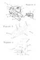
- FIG. 1shows an exploded view of a flowmeter according to the invention, the assembled flowmeter being shown in FIG. 2 ;
- FIG. 3illustrates part of an electric connector for such a flowmeter
- FIG. 4illustrates part of the housing of such a flowmeter.
- FIGS. 1 and 2illustrate a flowmeter 1 typically for a beverage preparation machine such as a coffee machine.
- the flowmetermay be mounted in the fluid circuit of the beverage preparation machine as for example described in greater details in PCT/EP09/053368.
- Flowmeter 1has a housing formed of two assembled moulded bodies 2 , 4 delimiting an internal generally cylindrical measuring chamber 10 .
- the housingis formed by injection moulding.
- Housing 2 , 4contains a rotatable measuring body 3 in the form of a rotor or impeller.
- Body 3has a series of radial members 31 , e.g. fins or blades, on a rotatable shaft 32 extending centrally across the measuring chamber 10 .
- Shaft 32has a lower part 33 from which radial members 31 extend and an upper part 34 .
- Two cavities 35are provided in upper part 34 for housing a pair of magnets 36 of corresponding shape.
- Flowmeter 1has upper and lower point bearings for mounting opposite extremities 32 ′, 32 ′′ of rotatable shaft 32 in housing bodies 2 , 4 .
- These point bearingsare formed by protrusions of housing 2 , 4 extending into chamber 10 and by recesses in extremities 32 ′, 32 ′′ of rotatable shaft 32 forming a positioning counter-part for the protrusion, a lower protrusion in the form of a pin 11 and an upper recess 37 of this type forming part of the lower and upper bearings can be seen in FIG. 1 .
- the lower and upper bearingsare identical to ensure similar performance in all possible orientations.
- protrusions 11 and counter-parts 37are integrally formed with the moulded housing bodies 2 , 4 and the rotatable shaft 32 , respectively. In other words no additional component is needed for forming the bearing parts of the flowmeter. These may be moulded directly with the respective components, i.e. housing bodies 2 , 4 and shaft 32 .
- the shaft or even the entire impeller 3may be made of POM; housing 2 , 4 may be made of PBT with 30 vol % glass beads as a filler.
- lower housing body 4is in the general shape of a cup and upper housing body 2 is in the general shape of a cover. It is understood that the lower and upper orientation merely refer to the particular orientations of the flowmeter as illustrated in the Figures. During use, flowmeter 1 may take any orientation or even change orientation.
- Rotatable shaft 32has a rotation axis 3 ′ that extends between a point bearing (not shown) located at cover body 2 and a facing point bearing 11 located in cup-like body 4 .
- Cup-like body 4has a rim 41 forming a reference surface 42 perpendicular to rotation axis, cover body 2 having an inner face 22 that is urged on reference surface 42 for precisely setting a spacing between the point bearings 11 so as to hold and allow free rotation of shaft 32 therebetween.
- Cup-like body 4has four spaced apart hooks 45 that are evenly distributed on rim 41 and that cooperate with corresponding passages 25 and hook retaining parts 26 at the periphery of cover body 2 to form a bayonet connection.
- the spacing between the point bearingsis not affected by this locking. This spacing is entirely determined by the geometry (and position) of reference surface 42 so that tight tolerances for the bearings can be provided even though they are formed by moulding and not by additional diamonds.
- Each of the moulded bodies 2 , 4has a through-opening communicating with measuring chamber 10 for circulating liquid through such flowmeter.
- a tubular inlet 47is provided in cup-like body 4 and a tubular outlet 27 is provided in cover body 2 .
- the inlet and the outletcould of course be switched. Moreover, the inlet and the outlet could be located on the same moulded body.
- Sensor plug 5has a housing 51 which may be closed with a lid or otherwise sealed (not shown). Housing 51 has a pair of front hooks 52 for securing plug 5 in cavity 29 and delimits an inner chamber 53 .
- Chamber 53contains a Hall sensor on a PCB 54 with cables 55 for connection to a control unit (not shown), for instance of a beverage preparation machine such as a coffee machine.
- a triple barrieris provided: the walls of socket 28 in cover body 2 , housing 51 of plug 5 and a Kapton or other polyimide foil around PCB 54 , whereby PCB 54 with the Hall sensor is safely sealed.
- the Hall sensor, PCB 54 , housing 51 and cavity 29are so arranged and positioned that when plug 5 is secured in socket 28 , the Hall sensor is situated above extremity 32 ′′ with magnets 36 .
- PCB 54may be formed as part of a main board of the control unit to which cables 55 are connected. Hence, PCB 54 may be manufactured together with the control unit and then separated therefrom, e.g. cut away or broken off along a weakened line, before or after assembly of plug 5 before or after connection of cables 55 , and then secured with plug 5 into socket 28 . Hence, the manufacturing of the sensor device and its control unit can be simplified and optimised.
- the flowmetermay even be mounted directly onto the main board so that PCB 54 is an integral part of the main board and remains an integral part of the main board of the control unit, for instance as illustrated in greater details in WO 2009/043865 and in PCT/EP09/053368.
Landscapes
- Physics & Mathematics (AREA)
- Fluid Mechanics (AREA)
- General Physics & Mathematics (AREA)
- Measuring Volume Flow (AREA)
- Apparatus For Making Beverages (AREA)
Abstract
Description
Claims (19)
Applications Claiming Priority (4)
| Application Number | Priority Date | Filing Date | Title |
|---|---|---|---|
| EP09163815.5 | 2009-06-25 | ||
| EP09163815 | 2009-06-25 | ||
| EP09163815 | 2009-06-25 | ||
| PCT/EP2010/058691WO2010149602A1 (en) | 2009-06-25 | 2010-06-21 | Flowmeter structure for a beverage machine |
Publications (2)
| Publication Number | Publication Date |
|---|---|
| US20120090472A1 US20120090472A1 (en) | 2012-04-19 |
| US8789429B2true US8789429B2 (en) | 2014-07-29 |
Family
ID=41600423
Family Applications (1)
| Application Number | Title | Priority Date | Filing Date |
|---|---|---|---|
| US13/378,608Active2031-06-04US8789429B2 (en) | 2009-06-25 | 2010-06-21 | Flowmeter structure for a beverage machine |
Country Status (6)
| Country | Link |
|---|---|
| US (1) | US8789429B2 (en) |
| EP (1) | EP2446232B1 (en) |
| JP (1) | JP2012530920A (en) |
| CN (1) | CN102460086A (en) |
| CA (1) | CA2764127C (en) |
| WO (1) | WO2010149602A1 (en) |
Cited By (1)
| Publication number | Priority date | Publication date | Assignee | Title |
|---|---|---|---|---|
| US20150177034A1 (en)* | 2013-09-30 | 2015-06-25 | Lincoln Industrial Corporation | Flow measuring device for lubrication systems |
Families Citing this family (11)
| Publication number | Priority date | Publication date | Assignee | Title |
|---|---|---|---|---|
| US8789429B2 (en) | 2009-06-25 | 2014-07-29 | Nestec S.A. | Flowmeter structure for a beverage machine |
| CN102460087B (en)* | 2009-06-25 | 2016-04-13 | 雀巢产品技术援助有限公司 | Flow meter materials for beverage machines |
| DE202013100271U1 (en)* | 2013-01-21 | 2014-04-24 | Nestec S.A. | Flow measuring device for a beverage preparation machine |
| US20150245731A1 (en)* | 2014-02-28 | 2015-09-03 | Jeff Wu | Heating circulator cooker with openable pump housing |
| JP2019517833A (en) | 2016-04-12 | 2019-06-27 | ネステク ソシエテ アノニム | Fluid pumping device comprising a gear pump for a beverage dispenser |
| NL2017477B1 (en)* | 2016-09-16 | 2018-03-22 | Leonardus Josephus Petrus Peters Marcel | Detectie-eenheid voor het detecteren van een ronddraaiende meetkogel, alsmede stromingsmeter voorzien van de detectie-eenheid |
| DE102017008401A1 (en)* | 2017-09-07 | 2019-03-07 | Stiebel Eltron Gmbh & Co. Kg | Flow measuring device for a water-conducting building services equipment and home automation device |
| JP2019117174A (en)* | 2017-12-27 | 2019-07-18 | 株式会社A&M | Impeller type flow rate sensor and flow rate control system |
| EP3628195A1 (en) | 2018-09-27 | 2020-04-01 | Société des Produits Nestlé S.A. | Beverage preparation machine with recipient detection |
| US12390044B2 (en) | 2018-09-27 | 2025-08-19 | Societe Des Produits Nestle S.A. | Adaptive service unit of a beverage machine |
| IT202000017830A1 (en) | 2020-07-23 | 2022-01-23 | Giorgio Antonio De | SYSTEM FOR MEASURING THE FLOW OF A LIQUID |
Citations (45)
| Publication number | Priority date | Publication date | Assignee | Title |
|---|---|---|---|---|
| DE7738382U1 (en) | 1977-12-16 | 1978-04-13 | G. Kromschroeder Ag, 4500 Osnabrueck | ONE-PIECE GAS METER COMPONENT |
| US4101874A (en) | 1976-07-29 | 1978-07-18 | The Perkin-Elmer Corporation | Fluid flow indicator and flow switch |
| US4265127A (en) | 1978-06-02 | 1981-05-05 | Kimmon Manufacturing Co., Ltd. | Low meter system provided with a pulse generator |
| US4393724A (en) | 1981-06-12 | 1983-07-19 | Vdo Adolf Schindling Ag | Flow meter having a rotary body |
| US4430901A (en) | 1980-07-24 | 1984-02-14 | Brown Boveri Kent Limited | Fluid meter |
| JPS60106122A (en) | 1983-11-15 | 1985-06-11 | マルコン電子株式会社 | Electrolytic condenser |
| JPS61219835A (en) | 1985-03-20 | 1986-09-30 | デイグメ−ザ アクチエンゲゼルシヤフト デイギタ−レ メステヒニク | Measuring instrument for drink piping |
| US4666061A (en) | 1984-03-20 | 1987-05-19 | Digmesa Ag Digitale Messtechnik | Measuring device for beverage dispenser lines |
| JPH02135820A (en) | 1988-09-30 | 1990-05-24 | Siemens Ag | Method and apparatus for determining correction values for self-calibrating AD and DA converters |
| JPH07167689A (en) | 1993-12-14 | 1995-07-04 | Omron Corp | Flow rate sensor |
| US5433118A (en) | 1993-12-10 | 1995-07-18 | Contadores De Agua De Zaragoza | Magnetic turbine rotor for low flow fluid meter |
| US5679906A (en) | 1995-03-15 | 1997-10-21 | Micro Motion, Inc. | Coriolis effect mass flowmeter using a single rotor having a flexible sensing element |
| EP0841547A2 (en) | 1996-08-15 | 1998-05-13 | Digmesa Ag | Flowmeter |
| US5866824A (en) | 1997-01-24 | 1999-02-02 | American Meter Company | Gas turbine meter |
| US5876610A (en)* | 1997-03-19 | 1999-03-02 | Clack Corporation | Method and apparatus for monitoring liquid flow through an enclosed stream |
| US5943472A (en) | 1994-06-20 | 1999-08-24 | Seb S.A. | Device for producing hot water or steam on demand using a single distribution control member |
| US5965826A (en) | 1994-12-20 | 1999-10-12 | Schlumberger Industries, S.R.L. | Single jet liquid meter with improved sensitivity and regulation effect |
| USRE36401E (en) | 1991-11-07 | 1999-11-23 | M & Fc Holding Company, Inc. | Tandem rotor turbine meter and field calibration module |
| US6019003A (en)* | 1997-08-12 | 2000-02-01 | Cito Products, Inc. | Flow sensor turbine assembly with sapphire bearing and metallic insert |
| US6065352A (en) | 1999-06-18 | 2000-05-23 | American Meter Company | Turbine meter with a rotor having accuracy enhancing rotor blades |
| JP2001077920A (en) | 1999-09-07 | 2001-03-23 | Fujitsu Ltd | Exchange system |
| JP2001276816A (en) | 2000-03-30 | 2001-10-09 | Mitsubishi Rayon Co Ltd | Water purifier |
| JP2002005701A (en) | 2000-06-20 | 2002-01-09 | Shintoshi Service Center:Kk | Water metering system |
| US6481293B1 (en)* | 1997-03-19 | 2002-11-19 | Osmonics, Inc. | Elbow mounted turbine flowmeter |
| JP2003042819A (en) | 2001-08-02 | 2003-02-13 | Oval Corp | Vortex flowmeter |
| JP2005003552A (en) | 2003-06-12 | 2005-01-06 | Univ Nihon | Rotary blade device |
| JP2005105059A (en) | 2003-09-29 | 2005-04-21 | Mikuni Plast Kk | Molded product for underground or on ground installation |
| US7093503B1 (en)* | 2004-11-16 | 2006-08-22 | Energent Corporation | Variable phase turbine |
| DE202007003419U1 (en) | 2007-03-07 | 2007-04-26 | Imk Automotive Gmbh | Transverse toothed planetary gear for height adjustment of belt in vehicle, has sun wheel, planetary wheels and hollow wheel formed from plastic, where planetary wheels have teeth width that corresponds to value of their diameter |
| DE102006036948A1 (en) | 2006-08-06 | 2008-02-07 | Akdis, Mustafa, Dipl.-Ing. | blood pump |
| JP2008096394A (en) | 2006-10-16 | 2008-04-24 | Ricoh Elemex Corp | Flowmeter |
| JP2008164544A (en) | 2006-12-29 | 2008-07-17 | Takahata Seiko Kk | Water meter |
| JP2008209260A (en) | 2007-02-27 | 2008-09-11 | Techno Excel Co Ltd | Foreign matter corresponding impeller type flow rate sensor |
| JP2008215868A (en) | 2007-02-28 | 2008-09-18 | Miura Co Ltd | Impeller type flow meter |
| EP2017585A1 (en) | 2007-07-19 | 2009-01-21 | Gealan Formteile GmbH | Flow recording device |
| WO2009043865A2 (en) | 2007-10-04 | 2009-04-09 | Nestec S.A. | Heating device with an integrated thermoblock for a beverage preparation machine |
| WO2009074550A2 (en) | 2007-12-12 | 2009-06-18 | Nestec S.A. | Modular manufacturing of beverage production machines |
| WO2009130099A1 (en) | 2008-04-22 | 2009-10-29 | Nestec S.A. | Modular assembly of a beverage preparation machine |
| US7650801B2 (en) | 2005-09-08 | 2010-01-26 | M & Fc Holding Llc | Turbine flowmeter |
| US7665368B2 (en) | 2006-08-18 | 2010-02-23 | Abb Limited | Flow meter |
| US7997150B2 (en)* | 2006-04-07 | 2011-08-16 | Itron, Inc. | Magnetic drive assembly for petroleum and LPG meter |
| US8006569B2 (en) | 2009-06-12 | 2011-08-30 | Sensus Usa Inc. | Magnetic flow meter |
| US20120090472A1 (en) | 2009-06-25 | 2012-04-19 | Stefan Etter | Flowmeter structure for a beverage machine |
| US20120090406A1 (en)* | 2009-06-25 | 2012-04-19 | Stefan Etter | Flowmeter materials for a beverage machine |
| US8397586B2 (en) | 2010-03-22 | 2013-03-19 | Honeywell International Inc. | Flow sensor assembly with porous insert |
Family Cites Families (2)
| Publication number | Priority date | Publication date | Assignee | Title |
|---|---|---|---|---|
| JPS63167220U (en)* | 1987-04-21 | 1988-10-31 | ||
| WO2004111579A1 (en)* | 2003-06-12 | 2004-12-23 | Nihon University | Flowmeter |
- 2010
- 2010-06-21USUS13/378,608patent/US8789429B2/enactiveActive
- 2010-06-21JPJP2012516679Apatent/JP2012530920A/enactivePending
- 2010-06-21EPEP10725748.7Apatent/EP2446232B1/enactiveActive
- 2010-06-21CACA2764127Apatent/CA2764127C/enactiveActive
- 2010-06-21WOPCT/EP2010/058691patent/WO2010149602A1/enactiveApplication Filing
- 2010-06-21CNCN2010800280943Apatent/CN102460086A/enactivePending
Patent Citations (46)
| Publication number | Priority date | Publication date | Assignee | Title |
|---|---|---|---|---|
| US4101874A (en) | 1976-07-29 | 1978-07-18 | The Perkin-Elmer Corporation | Fluid flow indicator and flow switch |
| DE7738382U1 (en) | 1977-12-16 | 1978-04-13 | G. Kromschroeder Ag, 4500 Osnabrueck | ONE-PIECE GAS METER COMPONENT |
| US4265127A (en) | 1978-06-02 | 1981-05-05 | Kimmon Manufacturing Co., Ltd. | Low meter system provided with a pulse generator |
| US4430901A (en) | 1980-07-24 | 1984-02-14 | Brown Boveri Kent Limited | Fluid meter |
| US4393724A (en) | 1981-06-12 | 1983-07-19 | Vdo Adolf Schindling Ag | Flow meter having a rotary body |
| JPS60106122A (en) | 1983-11-15 | 1985-06-11 | マルコン電子株式会社 | Electrolytic condenser |
| US4666061A (en) | 1984-03-20 | 1987-05-19 | Digmesa Ag Digitale Messtechnik | Measuring device for beverage dispenser lines |
| JPS61219835A (en) | 1985-03-20 | 1986-09-30 | デイグメ−ザ アクチエンゲゼルシヤフト デイギタ−レ メステヒニク | Measuring instrument for drink piping |
| JPH02135820A (en) | 1988-09-30 | 1990-05-24 | Siemens Ag | Method and apparatus for determining correction values for self-calibrating AD and DA converters |
| USRE36401E (en) | 1991-11-07 | 1999-11-23 | M & Fc Holding Company, Inc. | Tandem rotor turbine meter and field calibration module |
| US5433118A (en) | 1993-12-10 | 1995-07-18 | Contadores De Agua De Zaragoza | Magnetic turbine rotor for low flow fluid meter |
| JPH07167689A (en) | 1993-12-14 | 1995-07-04 | Omron Corp | Flow rate sensor |
| US5943472A (en) | 1994-06-20 | 1999-08-24 | Seb S.A. | Device for producing hot water or steam on demand using a single distribution control member |
| US5965826A (en) | 1994-12-20 | 1999-10-12 | Schlumberger Industries, S.R.L. | Single jet liquid meter with improved sensitivity and regulation effect |
| US5679906A (en) | 1995-03-15 | 1997-10-21 | Micro Motion, Inc. | Coriolis effect mass flowmeter using a single rotor having a flexible sensing element |
| EP0841547A2 (en) | 1996-08-15 | 1998-05-13 | Digmesa Ag | Flowmeter |
| US5866824A (en) | 1997-01-24 | 1999-02-02 | American Meter Company | Gas turbine meter |
| US5876610A (en)* | 1997-03-19 | 1999-03-02 | Clack Corporation | Method and apparatus for monitoring liquid flow through an enclosed stream |
| US6481293B1 (en)* | 1997-03-19 | 2002-11-19 | Osmonics, Inc. | Elbow mounted turbine flowmeter |
| US6019003A (en)* | 1997-08-12 | 2000-02-01 | Cito Products, Inc. | Flow sensor turbine assembly with sapphire bearing and metallic insert |
| US6065352A (en) | 1999-06-18 | 2000-05-23 | American Meter Company | Turbine meter with a rotor having accuracy enhancing rotor blades |
| JP2001077920A (en) | 1999-09-07 | 2001-03-23 | Fujitsu Ltd | Exchange system |
| JP2001276816A (en) | 2000-03-30 | 2001-10-09 | Mitsubishi Rayon Co Ltd | Water purifier |
| US20030062300A1 (en) | 2000-03-30 | 2003-04-03 | Masaaki Okano | Water purifier |
| JP2002005701A (en) | 2000-06-20 | 2002-01-09 | Shintoshi Service Center:Kk | Water metering system |
| JP2003042819A (en) | 2001-08-02 | 2003-02-13 | Oval Corp | Vortex flowmeter |
| JP2005003552A (en) | 2003-06-12 | 2005-01-06 | Univ Nihon | Rotary blade device |
| JP2005105059A (en) | 2003-09-29 | 2005-04-21 | Mikuni Plast Kk | Molded product for underground or on ground installation |
| US7093503B1 (en)* | 2004-11-16 | 2006-08-22 | Energent Corporation | Variable phase turbine |
| US7650801B2 (en) | 2005-09-08 | 2010-01-26 | M & Fc Holding Llc | Turbine flowmeter |
| US7997150B2 (en)* | 2006-04-07 | 2011-08-16 | Itron, Inc. | Magnetic drive assembly for petroleum and LPG meter |
| DE102006036948A1 (en) | 2006-08-06 | 2008-02-07 | Akdis, Mustafa, Dipl.-Ing. | blood pump |
| US7665368B2 (en) | 2006-08-18 | 2010-02-23 | Abb Limited | Flow meter |
| JP2008096394A (en) | 2006-10-16 | 2008-04-24 | Ricoh Elemex Corp | Flowmeter |
| JP2008164544A (en) | 2006-12-29 | 2008-07-17 | Takahata Seiko Kk | Water meter |
| JP2008209260A (en) | 2007-02-27 | 2008-09-11 | Techno Excel Co Ltd | Foreign matter corresponding impeller type flow rate sensor |
| JP2008215868A (en) | 2007-02-28 | 2008-09-18 | Miura Co Ltd | Impeller type flow meter |
| DE202007003419U1 (en) | 2007-03-07 | 2007-04-26 | Imk Automotive Gmbh | Transverse toothed planetary gear for height adjustment of belt in vehicle, has sun wheel, planetary wheels and hollow wheel formed from plastic, where planetary wheels have teeth width that corresponds to value of their diameter |
| EP2017585A1 (en) | 2007-07-19 | 2009-01-21 | Gealan Formteile GmbH | Flow recording device |
| WO2009043865A2 (en) | 2007-10-04 | 2009-04-09 | Nestec S.A. | Heating device with an integrated thermoblock for a beverage preparation machine |
| WO2009074550A2 (en) | 2007-12-12 | 2009-06-18 | Nestec S.A. | Modular manufacturing of beverage production machines |
| WO2009130099A1 (en) | 2008-04-22 | 2009-10-29 | Nestec S.A. | Modular assembly of a beverage preparation machine |
| US8006569B2 (en) | 2009-06-12 | 2011-08-30 | Sensus Usa Inc. | Magnetic flow meter |
| US20120090472A1 (en) | 2009-06-25 | 2012-04-19 | Stefan Etter | Flowmeter structure for a beverage machine |
| US20120090406A1 (en)* | 2009-06-25 | 2012-04-19 | Stefan Etter | Flowmeter materials for a beverage machine |
| US8397586B2 (en) | 2010-03-22 | 2013-03-19 | Honeywell International Inc. | Flow sensor assembly with porous insert |
Non-Patent Citations (3)
| Title |
|---|
| Digmesa AG: Mar. 19, 2006, Data Sheet, "FHKSC Arnite using fastening pin with double pulse, Part No. 932-8503/XXX". Retrieved from the Internet, URL: http ://web.archive.org/web/20060319145216/www.digmesa. com/digmesa/upload/pdf/fhksc/932-8503xxx-GB.pdf (retrieved on Feb. 9, 2010). |
| Digmesa Data Sheet for Part No. 932-8503xxx, XP002567763, http://web.archive.org/web/20060319145216/www.digmesa.com/digmesa/upload/pdf/FHKSC/932-8503xxx-GB.pdf ; (2006). |
| International Search Report and Written Opinion, PCT/EP2010/058691, mailed Jul. 28, 2010. |
Cited By (3)
| Publication number | Priority date | Publication date | Assignee | Title |
|---|---|---|---|---|
| US20150177034A1 (en)* | 2013-09-30 | 2015-06-25 | Lincoln Industrial Corporation | Flow measuring device for lubrication systems |
| US9581474B2 (en)* | 2013-09-30 | 2017-02-28 | Lincoln Industrial Corporation | Flow measuring device for lubrication systems |
| US10209108B2 (en) | 2013-09-30 | 2019-02-19 | Lincoln Industrial Corporation | Flow measuring device for lubrication systems |
Also Published As
| Publication number | Publication date |
|---|---|
| US20120090472A1 (en) | 2012-04-19 |
| WO2010149602A1 (en) | 2010-12-29 |
| CN102460086A (en) | 2012-05-16 |
| EP2446232A1 (en) | 2012-05-02 |
| CA2764127C (en) | 2017-08-22 |
| JP2012530920A (en) | 2012-12-06 |
| CA2764127A1 (en) | 2010-12-29 |
| EP2446232B1 (en) | 2017-08-23 |
Similar Documents
| Publication | Publication Date | Title |
|---|---|---|
| US8789429B2 (en) | Flowmeter structure for a beverage machine | |
| US8714031B2 (en) | Flowmeter materials for a beverage machine | |
| EP2507594B1 (en) | Beverage machine | |
| US9101247B2 (en) | Flowmeter assembly for a beverage machine | |
| JP2012530920A5 (en) | ||
| EP3442383B1 (en) | A liquid pumping device comprising a gear pump for beverage dispenser |
Legal Events
| Date | Code | Title | Description |
|---|---|---|---|
| AS | Assignment | Owner name:NESTEC S.A., SWITZERLAND Free format text:ASSIGNMENT OF ASSIGNORS INTEREST;ASSIGNORS:ETTER, STEFAN;ZIEGLER, MARTIN;REEL/FRAME:027763/0719 Effective date:20090701 | |
| STCF | Information on status: patent grant | Free format text:PATENTED CASE | |
| MAFP | Maintenance fee payment | Free format text:PAYMENT OF MAINTENANCE FEE, 4TH YEAR, LARGE ENTITY (ORIGINAL EVENT CODE: M1551) Year of fee payment:4 | |
| AS | Assignment | Owner name:SOCIETE DES PRODUITS NESTLE S.A., SWITZERLAND Free format text:MERGER;ASSIGNOR:NESTEC S.A.;REEL/FRAME:049391/0756 Effective date:20190528 | |
| AS | Assignment | Owner name:SOCIETE DES PRODUITS NESTLE S.A., SWITZERLAND Free format text:CORRECTIVE ASSIGNMENT TO CORRECT THE ENGLISH TRANSLATION TO SHOW THE FULL AND CORRECT NEW NAME IN SECTION 51. PREVIOUSLY RECORDED AT REEL: 049391 FRAME: 0756. ASSIGNOR(S) HEREBY CONFIRMS THE MERGER;ASSIGNOR:NESTEC S.A.;REEL/FRAME:049853/0398 Effective date:20190528 | |
| AS | Assignment | Owner name:SOCIETE DES PRODUITS NESTLE S.A., SWITZERLAND Free format text:CORRECTIVE ASSIGNMENT TO CORRECT THE PATENT NUMBER 16062921 PREVIOUSLY RECORDED ON REEL 049391 FRAME 0756. ASSIGNOR(S) HEREBY CONFIRMS THE PATENT NUMBER SHOULD HAVE BEEN 16062912;ASSIGNOR:NESTEC S.A.;REEL/FRAME:054082/0165 Effective date:20190528 Owner name:SOCIETE DES PRODUITS NESTLE S.A., SWITZERLAND Free format text:CORRECTIVE ASSIGNMENT TO CORRECT THE PATENT NUMBER 16062921 PREVIOUSLY RECORDED ON REEL 049391 FRAME 0756. ASSIGNOR(S) HEREBY CONFIRMS THE PATENT NUMBER SHOULD HAVE BEEN 16062912;ASSIGNOR:NESTEC S.A.;REEL/FRAME:054082/0001 Effective date:20190528 | |
| MAFP | Maintenance fee payment | Free format text:PAYMENT OF MAINTENANCE FEE, 8TH YEAR, LARGE ENTITY (ORIGINAL EVENT CODE: M1552); ENTITY STATUS OF PATENT OWNER: LARGE ENTITY Year of fee payment:8 |