US8787409B2 - Method for discontinuously transferring data in a point-to-multipoint access network, central unit, and network termination unit - Google Patents
Method for discontinuously transferring data in a point-to-multipoint access network, central unit, and network termination unitDownload PDFInfo
- Publication number
- US8787409B2 US8787409B2US13/322,181US201013322181AUS8787409B2US 8787409 B2US8787409 B2US 8787409B2US 201013322181 AUS201013322181 AUS 201013322181AUS 8787409 B2US8787409 B2US 8787409B2
- Authority
- US
- United States
- Prior art keywords
- data
- subscriber
- network termination
- unit
- sided
- Prior art date
- Legal status (The legal status is an assumption and is not a legal conclusion. Google has not performed a legal analysis and makes no representation as to the accuracy of the status listed.)
- Active, expires
Links
Images

Classifications
- H—ELECTRICITY
- H04—ELECTRIC COMMUNICATION TECHNIQUE
- H04J—MULTIPLEX COMMUNICATION
- H04J3/00—Time-division multiplex systems
- H—ELECTRICITY
- H04—ELECTRIC COMMUNICATION TECHNIQUE
- H04L—TRANSMISSION OF DIGITAL INFORMATION, e.g. TELEGRAPHIC COMMUNICATION
- H04L1/00—Arrangements for detecting or preventing errors in the information received
- H04L1/004—Arrangements for detecting or preventing errors in the information received by using forward error control
- H04L1/0041—Arrangements at the transmitter end
- H—ELECTRICITY
- H04—ELECTRIC COMMUNICATION TECHNIQUE
- H04L—TRANSMISSION OF DIGITAL INFORMATION, e.g. TELEGRAPHIC COMMUNICATION
- H04L12/00—Data switching networks
- H04L12/28—Data switching networks characterised by path configuration, e.g. LAN [Local Area Networks] or WAN [Wide Area Networks]
- H—ELECTRICITY
- H04—ELECTRIC COMMUNICATION TECHNIQUE
- H04M—TELEPHONIC COMMUNICATION
- H04M11/00—Telephonic communication systems specially adapted for combination with other electrical systems
- H04M11/06—Simultaneous speech and data transmission, e.g. telegraphic transmission over the same conductors
- H04M11/062—Simultaneous speech and data transmission, e.g. telegraphic transmission over the same conductors using different frequency bands for speech and other data
- H—ELECTRICITY
- H04—ELECTRIC COMMUNICATION TECHNIQUE
- H04Q—SELECTING
- H04Q11/00—Selecting arrangements for multiplex systems
- H04Q11/0001—Selecting arrangements for multiplex systems using optical switching
- H04Q11/0062—Network aspects
- H04Q11/0067—Provisions for optical access or distribution networks, e.g. Gigabit Ethernet Passive Optical Network (GE-PON), ATM-based Passive Optical Network (A-PON), PON-Ring
- H—ELECTRICITY
- H04—ELECTRIC COMMUNICATION TECHNIQUE
- H04L—TRANSMISSION OF DIGITAL INFORMATION, e.g. TELEGRAPHIC COMMUNICATION
- H04L1/00—Arrangements for detecting or preventing errors in the information received
- H04L2001/0092—Error control systems characterised by the topology of the transmission link
- H04L2001/0093—Point-to-multipoint
- H—ELECTRICITY
- H04—ELECTRIC COMMUNICATION TECHNIQUE
- H04Q—SELECTING
- H04Q11/00—Selecting arrangements for multiplex systems
- H04Q11/0001—Selecting arrangements for multiplex systems using optical switching
- H04Q11/0062—Network aspects
- H04Q11/0071—Provisions for the electrical-optical layer interface
Definitions
- the inventionrelates to a method for transferring data in a point-to-multipoint access network from a central unit to a subscriber-sided network termination unit via a distribution network.
- Point-to-multipoint techniquesmore and more replace legacy point-to-point techniques in telecommunication, especially in the access area.
- the downstream directiondata for the different end users are time division multiplexed (TDM)
- TDMtime division multiplexed
- TDMAtime division multiple access technique
- a problemis that the energy consumption of the affected apparatus basically is rising with rising bit rate. For different reasons energy consumption should be kept low:
- This problem according to the inventionis solved by a method for discontinuously transferring data in a point-to-multipoint access network according to the teaching of claim 1 , by a central unit according to the teaching of claim 3 , and by a subscriber-sided network termination unit according to the teaching of claim 4 .
- the basic idea behindis to on the one hand put out of operation such part of a subscriber-sided network termination unit that is adapted to handle received data intended for the subscriber-sided network termination unit until such data really are foreseen to be received, and on the other hand to take measures that such subscriber-sided network termination unit can operate without prior reception of data foreseen for other subscriber-sided network termination units.
- the inventionwill be described based on an example lying in the field of gigabit passive optical networks with 10 Gb/s or 10 G PON.
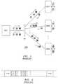
- FIG. 1shows a typical passive optical network, in which the method according to the invention can be applied.
- FIG. 2shows a typical data frame as used in passive optical networks.
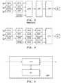
- FIG. 3shows a simplified block diagram of a central unit for such passive optical network according to the state of the art.
- FIG. 4shows a corresponding block diagram of a central unit according to the invention.
- FIG. 5shows a simplified block diagram of an optical network termination unit as an example of a subscriber-sided network termination unit according to the invention.
- FIG. 1a typical passive optical network PON as an example of a point-to-multipoint access network is considered in this invention.
- FIG. 1shows a central unit, here called optical line termination OLT, a distribution network DN, and a multiple of, here three, subscriber-sided network termination units, here called optical network termination units ONT 1 , ONT 2 , and ONTn.
- OLToptical line termination
- DNdistribution network
- ONT 1 , ONT 2 , and ONTnsubscriber-sided network termination units
- the distribution network DNshows a common optical link, not referenced here, reaching from the optical line termination OLT to an optical splitter SP and a multiple of separate optical links, also not referenced here, from the splitter to one of the optical network termination units ONT 1 , ONT 2 , and ONTn each.
- optical splitter SPnormally is a passive optical element that functions as splitter in the downlink direction towards the end users assigned to the optical network termination units ONT 1 , ONT 2 , and ONTn, and as a combiner in the uplink direction from the end users towards the optical line termination OLT.
- each optical network termination unit ONT 1 , ONT 2 , and ONTnreceives all data destined for all optical network termination units ONT 1 , ONT 2 , and ONTn, including the other ones. So actually it has to cope with a continuous data stream though only a discontinuous, bursty data stream is destined for it.
- FIG. 2shows a typical data frame as used in passive optical networks.
- Such data framespractically are periodical and a frame length of 125 microseconds is widely used in telecommunication.
- a framestarts with a frame header FHD and is followed by consecutive payload sections each consisting of a payload header PLH and a payload body PLn, here shown the payload bodies PL 1 , PL 2 , PL 3 , and PL 4 .
- the payload headers PLHall have a fixed length and a standardized structure, depending on the used standard or protocol, the payload bodies' contents are free and sometimes, also depending on the used standard or protocol, even the lengths are variable.
- a frame header FHDa remainder of a payload section started in the previous frame may be completed.
- Not used capacitynormally leads to filler bits or dummy payload sections at the end of a frame. In any event a continuous bit clock is used for synchronization purposes.
- FIG. 3shows the conditioning of data streams like such shown in FIG. 2 , as known from the state of the art.
- FIG. 3shows three encoders ENC, three channel framing units CFR, a line framing header unit LFRH, a line framing unit LFR, a scrambler unit SCR, a forward error correction unit FEC, and a box OL representing an optical line.
- a multiple of, here three, independent data input streams DI 1 , DI 2 , and DI 3pass assigned encoders ENC and channel framing units CFR, before they are forwarded together with the output data of the line framing header unit LFRH to the line framing unit LFR, and from there a multiplexed signal is transferred via the scrambler unit SCR and the forward error correction unit FEC to the optical line OL.
- a multiple of, here three, independent data input streams DI 1 , DI 2 , and DI 3first is encoded in respective encoders ENC, one per data stream. This ensures privacy, because as already mentioned and as seen in FIG. 1 , every optical network termination unit ONT 1 , ONT 2 , and ONTn receives all data destined for all destinations.
- the independent data input streams DI 1 , DI 2 , and DI 3are considered here as representing the contents of one connection or channel each. Such content has to be transferred transparently from this input to a respective output of an assigned optical network termination unit ONT. Normally at the output of such optical network termination unit ONT the terminal of a single subscriber or similar equipment is connected, but principally even a further distribution network could be connected.
- Either of the data input streams DI 1 , DI 2 , and DI 3might be a continuous or a discontinuous one; and the different data streams might even be out of synchronism with respect to one another.
- the first step towards multiplexingis the unification and synchronization of the different data streams. At least before multiplexing a common data clock is necessary. For achieving such purposes each of the data input streams DI 1 , DI 2 , and DI 3 after being encoded undergoes a channel framing in separate channel framing units CFR.
- the data units of the data input streams DI 1 , DI 2 , and DI 3are processed each into a payload header PLH and a payload body like PL 1 , PL 2 , PL 3 , or PL 4 as already mentioned in the description of FIG. 2 .
- the data streamsare filled with filler bits or dummy data units to ensure a continuous data stream also for data streams not utilizing the full provided capacity.
- these encoded and framed data input streamsare input to the line framing unit LFR, where they are multiplexed, normally in an asynchronous manner, to a common data frame, as shown in FIG. 2 .
- LFRline framing unit
- the capacity of the common linkis less than the sum of the capacities of the data input streams. So first filler bits or dummy data units coming from the different data input streams are omitted and at the end of a frame either new filler bits or dummy data units are inserted or remainders are forwarded to the next frame.
- Such measuresimply reversing at the receiving side, here the respective optical network termination unit ONT 1 , ONT 2 , to ONTn.
- the measures exceeding the combination of data for different optical network termination units ONT 1 , ONT 2 , and ONTnare applied to the data of either of the data input streams DI 1 , DI 2 , and DI 3 and thus are applied before such data are combined with data of the respective other data streams.
- FIG. 4shows three encoders ENC, three channel framing units CFR, a line framing header unit LFRH, four scrambler units SCR, four forward error correction units FEC, a line framing unit LFR, and a box OL representing an optical line.
- FIGS. 3 and 4may be achieved by using separate hardware for each and every block, by hardware common to some or all blocks, by software individual to each and every block or by software common to some or all blocks.
- FIG. 5shows a simplified block diagram of an example of an optical network termination unit that according to the invention is adapted to not continuously processing an incoming data stream.
- FIG. 5shows an optical network termination unit ONT, that includes a transmission function part TFP and a clock CL.
- the transmission function part TFPis adapted to cooperate with the forward error correction unit FEC, the scrambler unit SCR, the channel framing unit CFR, and the encoder ENC processing the data input stream DI 1 , DI 2 , or DI 3 associated to this optical network termination unit ONT. To this end may be it also needs information from the line framing header unit LFRH. To this end it needs to work only when such data arrive at its input and according to the invention it is adapted to be put out of operation controlled by the clock CL.
- the clock CLhas to maintain synchronization in times the transmission function part TFP is out of operation, is adapted to put out of operation such part, when applicable, and is adapted to reverse such putting out of operation when data income is expected.
- the times when data income is to be expectedmay be fixed while putting such optical network termination unit ONT into operation, when establishing a connection to this optical network termination unit ONT, or may be reported once per frame in the frame header FHD or even in subsequent reports within the different payload headers PLH.
- the sleep times of the transmission function part TFPmay be longer or shorter and the reduction in energy consumption may be higher or lower. In order to ensure correct operation, a timely wake up for re-synchronization and re-alignment may be necessary. But this is not a principle problem.
Landscapes
- Engineering & Computer Science (AREA)
- Computer Networks & Wireless Communication (AREA)
- Signal Processing (AREA)
- Small-Scale Networks (AREA)
- Communication Control (AREA)
- Optical Communication System (AREA)
Abstract
Description
- Equipment sometimes is located remotely and works battery-backed with solar energy.
- During times of power outage a battery-backed operation might be foreseen.
- Waste heat may be disturbing.
- Environmental concerns like carbon footprint more and more play a role.
Claims (10)
Applications Claiming Priority (4)
| Application Number | Priority Date | Filing Date | Title |
|---|---|---|---|
| EP09305523.4 | 2009-06-10 | ||
| EP09305523AEP2262178A1 (en) | 2009-06-10 | 2009-06-10 | Method for discontinuously transferring data in a point-to-multipoint access network, central unit, and network termination unit |
| EP09305523 | 2009-06-10 | ||
| PCT/EP2010/056167WO2010142500A1 (en) | 2009-06-10 | 2010-05-06 | Method for discontinuously transferring data in a point-to-multipoint access network, central unit, and networking termination unit |
Publications (2)
| Publication Number | Publication Date |
|---|---|
| US20120120832A1 US20120120832A1 (en) | 2012-05-17 |
| US8787409B2true US8787409B2 (en) | 2014-07-22 |
Family
ID=41278705
Family Applications (1)
| Application Number | Title | Priority Date | Filing Date |
|---|---|---|---|
| US13/322,181Active2030-08-08US8787409B2 (en) | 2009-06-10 | 2010-05-06 | Method for discontinuously transferring data in a point-to-multipoint access network, central unit, and network termination unit |
Country Status (6)
| Country | Link |
|---|---|
| US (1) | US8787409B2 (en) |
| EP (1) | EP2262178A1 (en) |
| JP (1) | JP5430753B2 (en) |
| KR (1) | KR101435415B1 (en) |
| CN (1) | CN102461077B (en) |
| WO (1) | WO2010142500A1 (en) |
Families Citing this family (2)
| Publication number | Priority date | Publication date | Assignee | Title |
|---|---|---|---|---|
| US8234411B2 (en) | 2010-09-02 | 2012-07-31 | Comcast Cable Communications, Llc | Providing enhanced content |
| CN114374466B (en)* | 2020-10-14 | 2023-09-29 | 中国电信股份有限公司 | Coding block processing method and related equipment |
Citations (15)
| Publication number | Priority date | Publication date | Assignee | Title |
|---|---|---|---|---|
| US5144669A (en)* | 1987-09-14 | 1992-09-01 | British Telecommunications Public Limited Company | Method of communicating digital signals and receiver for use with such method |
| US5473696A (en)* | 1993-11-05 | 1995-12-05 | At&T Corp. | Method and apparatus for combined encryption and scrambling of information on a shared medium network |
| US5550825A (en)* | 1991-11-19 | 1996-08-27 | Scientific-Atlanta, Inc. | Headend processing for a digital transmission system |
| US5867490A (en)* | 1996-11-05 | 1999-02-02 | Worldspace International Network, Inc. | Direct radio broadcast receiver for providing frame synchronization and correlation for time division multiplexed transmissions |
| WO2002035906A2 (en) | 2000-11-01 | 2002-05-10 | Actelis Networks Ltd. | High speed access system over copper cable plant |
| US6724727B2 (en)* | 2001-12-03 | 2004-04-20 | Nokia Corporation | Policy-based forward error correction in packet networks |
| US6738935B1 (en)* | 2000-02-07 | 2004-05-18 | 3Com Corporation | Coding sublayer for multi-channel media with error correction |
| US20050135803A1 (en) | 2003-12-18 | 2005-06-23 | Hak-Phil Lee | Gigabit ethernet passive optical network and method for accurately detecting data errors |
| US7171121B1 (en) | 2000-11-13 | 2007-01-30 | Nortel Networks Limited | Optical network subscriber access architecture |
| US7209493B2 (en)* | 2001-09-26 | 2007-04-24 | Nec Corporation | Multiplex transmission system and multiplex transmitter |
| US20070166038A1 (en)* | 1999-06-16 | 2007-07-19 | Nec Corporation | Wavelength-division multiplexed optical transmission system |
| US7453929B2 (en)* | 1999-02-23 | 2008-11-18 | Actelis Networks Ltd. | High speed access system over copper cable plant |
| US20090168812A1 (en)* | 2008-01-02 | 2009-07-02 | Cisco Technology, Inc. | Secure Combined Interoperable Multiplexing |
| US20100074350A1 (en)* | 2006-11-06 | 2010-03-25 | Qualcomm Incorporated | Codeword level scrambling for mimo transmission |
| US20100246585A1 (en)* | 2005-11-01 | 2010-09-30 | Metanoia Technologies, Inc. | Multiple Channel Digital Subscriber Line Framer/Deframer System and Method |
Family Cites Families (4)
| Publication number | Priority date | Publication date | Assignee | Title |
|---|---|---|---|---|
| JP4490166B2 (en)* | 2004-05-19 | 2010-06-23 | 三菱電機株式会社 | Station side equipment |
| CN100584103C (en)* | 2005-03-10 | 2010-01-20 | 华为技术有限公司 | Signal dispatching method and system in optical transmission network |
| US7660528B2 (en)* | 2005-05-13 | 2010-02-09 | Teknovus, Inc. | Method and system for mitigating Raman crosstalk in an Ethernet passive optical network |
| CN101026427B (en)* | 2006-02-17 | 2010-08-18 | 中兴通讯股份有限公司 | Device and method for realizing multi-channel low-speed signal and one-channel high speed signal two-way conversion |
- 2009
- 2009-06-10EPEP09305523Apatent/EP2262178A1/ennot_activeWithdrawn
- 2010
- 2010-05-06JPJP2012514406Apatent/JP5430753B2/ennot_activeExpired - Fee Related
- 2010-05-06KRKR1020117029364Apatent/KR101435415B1/ennot_activeExpired - Fee Related
- 2010-05-06CNCN201080025895.4Apatent/CN102461077B/ennot_activeExpired - Fee Related
- 2010-05-06USUS13/322,181patent/US8787409B2/enactiveActive
- 2010-05-06WOPCT/EP2010/056167patent/WO2010142500A1/enactiveApplication Filing
Patent Citations (15)
| Publication number | Priority date | Publication date | Assignee | Title |
|---|---|---|---|---|
| US5144669A (en)* | 1987-09-14 | 1992-09-01 | British Telecommunications Public Limited Company | Method of communicating digital signals and receiver for use with such method |
| US5550825A (en)* | 1991-11-19 | 1996-08-27 | Scientific-Atlanta, Inc. | Headend processing for a digital transmission system |
| US5473696A (en)* | 1993-11-05 | 1995-12-05 | At&T Corp. | Method and apparatus for combined encryption and scrambling of information on a shared medium network |
| US5867490A (en)* | 1996-11-05 | 1999-02-02 | Worldspace International Network, Inc. | Direct radio broadcast receiver for providing frame synchronization and correlation for time division multiplexed transmissions |
| US7453929B2 (en)* | 1999-02-23 | 2008-11-18 | Actelis Networks Ltd. | High speed access system over copper cable plant |
| US20070166038A1 (en)* | 1999-06-16 | 2007-07-19 | Nec Corporation | Wavelength-division multiplexed optical transmission system |
| US6738935B1 (en)* | 2000-02-07 | 2004-05-18 | 3Com Corporation | Coding sublayer for multi-channel media with error correction |
| WO2002035906A2 (en) | 2000-11-01 | 2002-05-10 | Actelis Networks Ltd. | High speed access system over copper cable plant |
| US7171121B1 (en) | 2000-11-13 | 2007-01-30 | Nortel Networks Limited | Optical network subscriber access architecture |
| US7209493B2 (en)* | 2001-09-26 | 2007-04-24 | Nec Corporation | Multiplex transmission system and multiplex transmitter |
| US6724727B2 (en)* | 2001-12-03 | 2004-04-20 | Nokia Corporation | Policy-based forward error correction in packet networks |
| US20050135803A1 (en) | 2003-12-18 | 2005-06-23 | Hak-Phil Lee | Gigabit ethernet passive optical network and method for accurately detecting data errors |
| US20100246585A1 (en)* | 2005-11-01 | 2010-09-30 | Metanoia Technologies, Inc. | Multiple Channel Digital Subscriber Line Framer/Deframer System and Method |
| US20100074350A1 (en)* | 2006-11-06 | 2010-03-25 | Qualcomm Incorporated | Codeword level scrambling for mimo transmission |
| US20090168812A1 (en)* | 2008-01-02 | 2009-07-02 | Cisco Technology, Inc. | Secure Combined Interoperable Multiplexing |
Also Published As
| Publication number | Publication date |
|---|---|
| JP5430753B2 (en) | 2014-03-05 |
| EP2262178A1 (en) | 2010-12-15 |
| KR20120026085A (en) | 2012-03-16 |
| CN102461077B (en) | 2016-01-20 |
| WO2010142500A1 (en) | 2010-12-16 |
| JP2012529818A (en) | 2012-11-22 |
| CN102461077A (en) | 2012-05-16 |
| US20120120832A1 (en) | 2012-05-17 |
| KR101435415B1 (en) | 2014-08-29 |
Similar Documents
| Publication | Publication Date | Title |
|---|---|---|
| EP2416506B1 (en) | Signal transmission processing method and device, and distributed base station | |
| KR101363541B1 (en) | Method and apparatus for encoding and decoding data | |
| US6430201B1 (en) | Method and apparatus for transporting gigabit ethernet and fiber channel signals in wavelength-division multiplexed systems | |
| EP3468075B1 (en) | Method, apparatus, and network system for sending and receiving services | |
| US8199772B2 (en) | Systems and methods for synchronous generic framing protocol mapping | |
| US10333644B2 (en) | Encapsulating digital communications signals for transmission on an optical link | |
| EP2323419B1 (en) | A method, a device and a system for constant rate data stream transmission | |
| US7278081B1 (en) | Optical transport network frame structure with in-band data channel and forward error correction | |
| US20080155255A1 (en) | Encryption apparatus | |
| US7028241B1 (en) | Optical transport network frame structure with dynamically allocable in-band data channel and forward error correction byte capacity | |
| US8787409B2 (en) | Method for discontinuously transferring data in a point-to-multipoint access network, central unit, and network termination unit | |
| CN113287266A (en) | Data transmission method, network chip and communication system | |
| US8503487B2 (en) | Communication methods and apparatuses | |
| US20080212560A1 (en) | Encoding for efficient use of an upstream channel in burst mode | |
| US9774458B2 (en) | Method for transporting Ethernet and non-Ethernet traffic over the same medium | |
| CN105027451B (en) | Method and device for downlink forward error correction on-off control in XG-PON1 and NG-PON2 TWDM-PON systems | |
| CN111225301B (en) | Device and method for mutual conversion between 8B/10B code and 64B/66B code | |
| JP5293107B2 (en) | Communication apparatus and communication method | |
| EP2088707A1 (en) | Method and device for processing data in an optical network and communication system comprising such device | |
| US7126943B2 (en) | Method and apparatus for interfacing a parallel connection | |
| JP5504087B2 (en) | Station-side terminator, communication system, and transmission control method | |
| JPH1132008A (en) | Optical transmission equipment | |
| KR20020093294A (en) | Data process apparatus and method for transmission convergence layer of Passive Optical Network | |
| AU2416301A (en) | Method and apparatus for transparent transmission between a tdm network and a packet or cell based network | |
| CN101803297B (en) | Method and device for transparent transmission of Ethernet signals through Ethernet switches |
Legal Events
| Date | Code | Title | Description |
|---|---|---|---|
| AS | Assignment | Owner name:ALCATEL LUCENT, FRANCE Free format text:ASSIGNMENT OF ASSIGNORS INTEREST;ASSIGNOR:KRIMMEL, HEINZ-GEORG;REEL/FRAME:027276/0339 Effective date:20100605 | |
| AS | Assignment | Owner name:CREDIT SUISSE AG, NEW YORK Free format text:SECURITY AGREEMENT;ASSIGNOR:LUCENT, ALCATEL;REEL/FRAME:029821/0001 Effective date:20130130 Owner name:CREDIT SUISSE AG, NEW YORK Free format text:SECURITY AGREEMENT;ASSIGNOR:ALCATEL LUCENT;REEL/FRAME:029821/0001 Effective date:20130130 | |
| FEPP | Fee payment procedure | Free format text:PAYOR NUMBER ASSIGNED (ORIGINAL EVENT CODE: ASPN); ENTITY STATUS OF PATENT OWNER: LARGE ENTITY | |
| STCF | Information on status: patent grant | Free format text:PATENTED CASE | |
| AS | Assignment | Owner name:ALCATEL LUCENT, FRANCE Free format text:RELEASE BY SECURED PARTY;ASSIGNOR:CREDIT SUISSE AG;REEL/FRAME:033868/0555 Effective date:20140819 | |
| AS | Assignment | Owner name:WSOU INVESTMENTS, LLC, CALIFORNIA Free format text:ASSIGNMENT OF ASSIGNORS INTEREST;ASSIGNOR:ALCATEL LUCENT;REEL/FRAME:045085/0001 Effective date:20171222 | |
| FEPP | Fee payment procedure | Free format text:MAINTENANCE FEE REMINDER MAILED (ORIGINAL EVENT CODE: REM.) | |
| FEPP | Fee payment procedure | Free format text:SURCHARGE FOR LATE PAYMENT, LARGE ENTITY (ORIGINAL EVENT CODE: M1554) | |
| MAFP | Maintenance fee payment | Free format text:PAYMENT OF MAINTENANCE FEE, 4TH YEAR, LARGE ENTITY (ORIGINAL EVENT CODE: M1551) Year of fee payment:4 | |
| AS | Assignment | Owner name:OT WSOU TERRIER HOLDINGS, LLC, CALIFORNIA Free format text:SECURITY INTEREST;ASSIGNOR:WSOU INVESTMENTS, LLC;REEL/FRAME:056990/0081 Effective date:20210528 | |
| FEPP | Fee payment procedure | Free format text:MAINTENANCE FEE REMINDER MAILED (ORIGINAL EVENT CODE: REM.); ENTITY STATUS OF PATENT OWNER: LARGE ENTITY | |
| FEPP | Fee payment procedure | Free format text:7.5 YR SURCHARGE - LATE PMT W/IN 6 MO, LARGE ENTITY (ORIGINAL EVENT CODE: M1555); ENTITY STATUS OF PATENT OWNER: LARGE ENTITY | |
| MAFP | Maintenance fee payment | Free format text:PAYMENT OF MAINTENANCE FEE, 8TH YEAR, LARGE ENTITY (ORIGINAL EVENT CODE: M1552); ENTITY STATUS OF PATENT OWNER: LARGE ENTITY Year of fee payment:8 |