US8786983B1 - Magnetic writer having a low aspect ratio two layer coil - Google Patents
Magnetic writer having a low aspect ratio two layer coilDownload PDFInfo
- Publication number
- US8786983B1 US8786983B1US13/532,658US201213532658AUS8786983B1US 8786983 B1US8786983 B1US 8786983B1US 201213532658 AUS201213532658 AUS 201213532658AUS 8786983 B1US8786983 B1US 8786983B1
- Authority
- US
- United States
- Prior art keywords
- turns
- turn
- pole
- coil
- transducer
- Prior art date
- Legal status (The legal status is an assumption and is not a legal conclusion. Google has not performed a legal analysis and makes no representation as to the accuracy of the status listed.)
- Active, expires
Links
Images


Classifications
- G—PHYSICS
- G11—INFORMATION STORAGE
- G11B—INFORMATION STORAGE BASED ON RELATIVE MOVEMENT BETWEEN RECORD CARRIER AND TRANSDUCER
- G11B5/00—Recording by magnetisation or demagnetisation of a record carrier; Reproducing by magnetic means; Record carriers therefor
- G11B5/127—Structure or manufacture of heads, e.g. inductive
- G11B5/17—Construction or disposition of windings
- G—PHYSICS
- G11—INFORMATION STORAGE
- G11B—INFORMATION STORAGE BASED ON RELATIVE MOVEMENT BETWEEN RECORD CARRIER AND TRANSDUCER
- G11B5/00—Recording by magnetisation or demagnetisation of a record carrier; Reproducing by magnetic means; Record carriers therefor
- G11B5/127—Structure or manufacture of heads, e.g. inductive
- G11B5/31—Structure or manufacture of heads, e.g. inductive using thin films
- G11B5/3109—Details
- G11B5/312—Details for reducing flux leakage between the electrical coil layers and the magnetic cores or poles or between the magnetic cores or poles
- G11B5/3123—Details for reducing flux leakage between the electrical coil layers and the magnetic cores or poles or between the magnetic cores or poles by using special coil configurations or conductors
Definitions
- Disk drivestypically use heads residing on sliders to read from and write to the magnetic media.
- a headtypically includes a read transducer and a write, or recording transducer.
- FIG. 1depicts a conventional magnetic recording transducer 10 .
- the magnetic recording transducer 10includes coils 12 , main pole 14 , insulators 16 , and shield 18 .
- the conventional write transducer 10typically utilizes photoresist as the insulator 16 .
- the return shield 18is typically formed of two separate pieces— 18 A and 18 B.
- the coil 12has three turns. Typically, three turns are required to obtain a sufficient field in the yoke of the pole 14 .
- the trend in magnetic recordingis to higher densities and higher data rates.
- additional requirementsmay be placed on the conventional write transducer 10 .
- a faster field rise time and, therefore, faster magnetic field reversalsare desired.
- Faster timesgenerally require a shorter yoke length.
- a shorter yoke lengthalso corresponds to a smaller distance available for the coils 12 .
- the conventional transducers 10can only be shrunk to a limited extent because of the coil cross-section required to support the desired current and insulation between the turns.
- the length of the yoke for the transducers 10is typically 5 ⁇ m or longer.
- the write transducers 10may be unsuitable for use at higher data rates.
- a method and systemprovide a magnetic transducer having an air-bearing surface (ABS).
- the magnetic transducerincludes a write pole and at least one coil.
- the write polehas a pole tip and a yoke.
- the coil(s)energize the write pole.
- the coil(s)include a plurality of turns a first distance from the pole and at least one additional turn a second distance from the pole. The first distance is different from the second distance.
- the at least one additional turnextends over at least part of two of the plurality of turns, has a length in a stripe height direction perpendicular to the ABS and has a height in a down track direction. The length is greater than the height.
- FIG. 1is a diagram of a side view of a conventional write transducer.
- FIG. 2depicts a side view of an exemplary embodiment of a write transducer.
- FIG. 3depicts a side view of another exemplary embodiment of a write transducer.
- FIG. 4depicts a side view of another exemplary embodiment of a write transducer.
- FIG. 5depicts a side view of another exemplary embodiment of a write transducer.
- FIG. 6depicts a side view of another exemplary embodiment of a write transducer
- FIG. 7depicts a side view of another exemplary embodiment of a write transducer
- FIG. 8depicts a side view of another exemplary embodiment of a write transducer
- FIG. 8depicts a side view of another exemplary embodiment of a write transducer
- FIG. 10is a flow chart depicting an exemplary embodiment of a method for providing a write transducer.
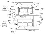
- FIG. 2depicts a side view of a portion of an exemplary embodiment of a disk drive. More specifically, FIG. 2 depicts a portion of a write transducer 100 .
- the write transducer 100may be part of a merged head that also includes a read transducer and which resides in a disk drive. For simplicity, components are omitted. In addition, for clarity, FIG. 2 is not drawn to scale.
- the magnetic transducer 100has a write pole 101 as well as coils 120 and 130 .
- the write pole 101includes main pole 102 and auxiliary pole 106 . Also shown are shield 108 and insulators 104 and 110 .
- the pole 101has a pole tip opposite to the portion of the shield 108 at the ABS and a yoke which lies between the coils 120 and 130 .
- the pole 101may be a perpendicular magnetic recording (PMR) pole.
- the transducer 100may be a PMR transducer.
- the pole 101 and transducermay be used in other writers.
- the transducer 100may be an energy assisted magnetic recording (EAMR) transducer. In such a case, optics (not shown) are typically included.
- a read transducermay also be coupled with the write transducer 100 .
- the shield 108is a single piece. However, in other embodiments, the shield 108 may have multiple pieces.
- the coils 120 and 130are conductive and carry a write current used to energize the pole.
- the coils 120 and 130may be separate, pancake coils. In other embodiments, the coils 120 and 130 form a single helical coil.
- the insulator 104may include several different insulators and/or may be formed in multiple fabrication steps.
- the insulator 104is nonmagnetic and insulates the turns 122 , 124 , 126 and 128 of the coil 120 .
- Another, analogous insulator 110may be used to insulate the turns 132 , 134 , 136 and 138 of the coil 130 .
- the insulators 104 / 110may be aluminum oxide.
- the aluminum oxideis deposited via atomic layer deposition (ALD), the thickness of the insulator between turns 132 , 134 and 136 may be not more than approximately 0.25 ⁇ m. In some embodiments, the thickness of the insulator is 0.05 ⁇ m-0.25 ⁇ m. The distance between the layer including turns 132 , 134 and 136 and the layer including turn 138 may be not more than approximately 0.25 ⁇ m. In some embodiments, the distance between the layers is 0.05 ⁇ m-0.25 ⁇ m. However, in other embodiments, the insulators 104 / 110 may include other materials Including but not limited to photoresist.
- the coil 120includes turns 122 , 124 , 126 and 128 .
- the coil 130includes turns 132 , 134 , 136 and 138 .
- each of the coils 120 and 130includes four turns.
- the coil 120includes two layers of turns.
- the coil 120may include a single layer of turns.
- the coil 130includes two sets of turns. The first set includes multiple turns 132 , 134 , and 136 .
- the second setincludes a single turn 138 . In another embodiment, the second set may include multiple turns.
- the first set of turns 132 , 134 and 136is a first distance, d 1 , from the pole 101 while the second set 138 is a second distance, d 2 , from the pole 101 that is different from the first distance.
- the coil 130includes two layers of turns.
- the turn 138has a length in the stripe height direction perpendicular to the ABS and a height in a down track direction. The length is greater than the height. Thus, the turn 138 is longer than it is tall. Consequently, the turn 138 may be viewed as having a low aspect ratio.
- the turn 138extends over more than one of the turns 132 , 134 and 136 in the other layer. In the embodiment shown, the turn 138 extends over at least a portion of each of the turns 132 , 134 and 136 . In some embodiments, the turn 138 extends over at least half of the outer turns 132 and 136 .
- the turn 138extends to the edge turn 132 closest to the ABS and to the edge of the turn 136 furthest from the ABS. In another embodiment, the turn 138 may extend over some or all of only two turns 132 and 134 or turns 134 and 136 . In addition, the turns in different layers of the coil 130 may have different aspect ratios. Thus, in the embodiment shown, the turn 138 has a different aspect ratio from the turns 132 , 134 and 136 . However, in at least some embodiments, the cross-sectional area of the turn 138 has the substantially the same cross-sectional area as the turns 132 , 134 and 136 . In such embodiments, each of the turns 132 , 134 , 136 and 138 may have the same current density.
- each turn 122 , 124 , 126 , 128 , 132 , 134 , 136 and/or 138may not be vertical and/or may be curved.
- both coils 120 and 130have turns 128 and 138 , respectively, that are wider than they are tall and extend over multiple turns in the other layer.
- only one of the coils 120 or 130has such a turn 128 or 138 . In such a case, the coil 130 is desired to have such a turn 138 because there may be less space in the region in which the coil 130 resides.
- the length of the coil 130 in the stripe height directionmay be reduced while the current carrying ability of the coils 120 and 130 may be maintained.
- the turns 132 , 134 , 136 and 138do not extend as far in the stripe height direction as a four turn coil (not shown) having a single layer of coils.
- the coil 130extends not more than 4.5 ⁇ m in the stripe height direction. In some such embodiments, the coil 130 extends not more than 3 ⁇ m in the stripe height direction. Because the turn 138 has a height that is less than its length, the shield 108 may have a lower profile in the down track direction.
- the magnetic transducer 100may have improved performance at high data rates. Because of the configuration of the turn 128 and 138 , the coils 120 and 130 may occupy less space in the stripe height direction. The magnetic transducer 100 may have more turns (e.g. four) than a three-turn coil occupying the same amount of space in the stripe height direction. The yoke length of the transducer 100 may be the same as that of a transducer having only one layer of turns corresponding to the turns 132 , 134 and 136 . Conversely, the yoke length of the transducer 100 may be shorter than that of a transducer having a single coil layer of four turns.
- the transducer 100may provide more current around the pole 101 because of the turn 138 .
- the transducer 100may have an extra turn, but have a yoke length that is not greater than the yoke length of the transducer 10 .
- the length of the yoke of the pole 101may be not more than 4.5 ⁇ m.
- the yoke length of the pole 101may be not more than 3.0 ⁇ m.
- a pole 101may have a yoke length that is not greater than the yoke length of a conventional transducer but provide more current (e.g. twenty-five percent more current) to the pole 101 because of the extra turn.
- the yoke length of the transducer 100may be less than that of a conventional transducer having the same number of turns, the rise time of the transducer 100 may be reduced. Performance of the transducer 100 may thus be improved.
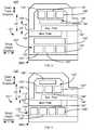
- FIG. 3depicts a side view of an exemplary embodiment of a magnetic recording transducer 100 ′.
- the magnetic transducer 100 ′is analogous to the magnetic transducer 100 . Consequently, analogous components are labeled similarly.
- the magnetic write transducer 100 ′thus includes a write pole 101 ′ having a main pole 102 ′ and auxiliary pole 106 ′, insulators 104 ′ and 110 ′, shield 108 ′ and coils 120 ′ and 130 ′ that are analogous to the write pole 101 having the main pole 102 and auxiliary pole 106 , the insulator 104 and 110 , the shield 108 , and the coils 120 and 130 , respectively.
- the pole 101 ′may be a PMR pole.
- the transducer 100 ′may be a PMR transducer.
- the pole 101 ′ and transducermay be used in other writers.
- the transducer 100 ′may be an EAMR transducer.
- a read transducermay also be coupled with the write transducer 100 ′.
- the coils 120 ′ and 130 ′are conductive and carry a write current used to energize the pole.
- the coils 120 ′ and 130 ′may be separate, pancake coils.
- the coils 120 ′ and 130 ′form a single helical coil.
- the insulators 104 ′ and 110 ′may include several different insulators and/or may be formed in multiple fabrication steps.
- the insulator 110 ′is nonmagnetic and insulates the turns 132 ′, 134 ′, 136 ′ and 138 ′ of the coil 130 ′.
- the insulator 104 ′ and 110 ′may include aluminum oxide and may be formed using ALD. Thus, the spacing between the turns 132 ′, 134 ′, 136 ′ and 138 ′ may be small, for example on the order of 0.25 ⁇ m or less.
- the coils 120 ′ and 130 ′are analogous to the coils 120 and 130 , respectively.
- the coil 120 ′includes turns 122 ′, 124 ′, 126 ′ and 128 ′ analogous to the turns 122 , 124 , 126 and 128 , respectively.
- the coil 130 ′includes turns 132 ′, 134 ′, 136 ′ and 138 ′ that are analogous to the turns 132 , 134 , 136 and 138 .
- the turns 122 ′, 124 ′, 126 ′, 128 ′, 132 ′, 134 ′, 136 ′ and 138 ′may have an analogous configuration and operation to the turns 122 , 124 , 126 , 128 . 132 , 134 , 136 , and 138 , respectively.
- the coil 130 ′has two layers at different distances, d 1 ′ and d 2 ′, from the pole 101 ′.
- One layer of the coil 130 ′includes turns 132 ′, 134 ′ and 136 ′, while the other layer includes a turn 138 ′.
- the turn 138 ′has a height in the down track direction that is less than the length in the stripe height direction.
- the turn 138 ′extends over more than one of the turns 132 ′, 134 ′ and 136 ′ in the other layer. In some embodiments, the turn 138 ′ extends at least halfway under the turns 132 ′ and 136 ′. In some such embodiments, the turn 138 ′ extends to the edges of the turns 132 ′ and 134 ′ further from the central turn 134 ′. In addition, the turns in different layers of the coil 130 ′ may have different aspect ratios. In at least some embodiments, the cross-sectional area of the turn 138 ′ has the substantially the same cross-sectional area as the turns 132 ′, 134 ′ and 136 ′.
- both coils 120 ′ and 130 ′have turns 128 ′ and 138 ′, respectively, that are longer than they are tall and extend over multiple turns in the other layer.
- only one of the coils 120 ′ or 130 ′has such a turn 128 ′ or 138 ′.
- the coil 130 ′is desired to have such a turn 138 ′ because there may be less space in the region in which the coil 130 ′ resides.
- the position of the turn 138 ′ with respect to the pole 101 ′is opposite to that of the turns 132 ′, 134 ′ and 136 ′.
- the turn 138 ′is closer to the pole 101 ′ than the turns 132 ′, 134 ′ and 136 ′.
- the magnetic transducer 100 ′may share the benefits of the magnetic transducer 100 .
- the magnetic transducer 100 ′may have improved performance at high data rates.
- the coils 130 ′may occupy less space in the stripe height direction.
- the coil 130 ′extends not more than 4.5 ⁇ m in the stripe height direction.
- the coil 130 ′extends not more than 3 ⁇ m in the stripe height direction.
- the yokemay be shorter.
- the yoke lengthis not more than 4.5 ⁇ m. In some such embodiments, the yoke length is not more than 3 ⁇ m. The response time of the pole 101 ′ may thus be improved.
- FIG. 4depicts a side view of an exemplary embodiment of a magnetic recording transducer 100 ′′.
- FIG. 4is not to scale.
- the magnetic transducer 100 ′′is analogous to the magnetic transducers 100 and 100 ′. Consequently, analogous components are labeled similarly.
- the magnetic write transducer 100 ′′thus includes a write pole 101 ′′ having a main pole 102 ′′ and auxiliary pole 106 ′′, insulators 104 ′′ and 110 ′′, shield 108 ′′ and coils 120 ′′ and 130 ′′ that are analogous to the write pole 101 / 101 ′ having the main pole 102 / 102 ′ and auxiliary pole 106 / 106 ′, the insulator 104 / 104 ′ and 110 / 110 ′, the shield 108 / 108 ′, and the coils 120 / 120 ′ and 130 / 130 ′, respectively.
- the pole 101 ′′may be a PMR pole.
- the transducer 100 ′′may be a PMR transducer.
- the pole 101 ′′ and transducermay be used in other writers.
- the transducer 100 ′′may be an EAMR transducer.
- a read transducermay also be coupled with the write transducer 100 ′′.
- the coils 120 ′′ and 130 ′′are conductive and carry a write current used to energize the pole.
- the coils 120 ′′ and 130 ′′may be separate, pancake coils.
- the coils 120 ′′ and 130 ′′form a single helical coil.
- the insulators 104 ′′ and 110 ′′may include several different insulators and/or may be formed in multiple fabrication steps.
- the insulator 110 ′′is nonmagnetic and insulates the turns 132 ′′, 134 ′′, 136 ′′ and 138 ′′ of the coil 130 ′′.
- the insulator 104 ′′ and 110 ′′may include aluminum oxide and may be formed using ALD.
- the spacing between the turns 132 ′′, 134 ′′, 136 ′′ and 138 ′′may be small, for example on the order of 0.25 ⁇ m or less.
- the coils 120 ′′ and 130 ′′are analogous to the coils 120 / 120 ′ and 130 / 130 ′, respectively.
- the coil 120 ′′includes turns 122 ′′, 124 ′′, 126 ′′ and 128 ′′ analogous to the turns 122 / 122 ′, 124 / 124 ′, 126 / 126 ′ and 128 / 128 ′, respectively.
- the coil 130 ′includes turns 132 ′, 134 ′, 136 ′ and 138 ′ that are analogous to the turns 132 / 132 ′, 134 / 134 ′, 136 / 136 ′ and 138 / 138 ′.
- the turns 122 ′, 124 ′, 126 ′, 128 ′, 132 ′, 134 ′, 136 ′ and 138 ′may have an analogous configuration and operation to the turns 122 / 122 ′, 124 / 124 ′, 126 / 126 ′, 128 / 128 ′, 132 / 132 ′, 134 / 134 ′, 136 / 136 ′, and 138 / 138 ′, respectively.
- the coil 130 ′′has two layers at different distances, d 1 and d 2 , from the pole 101 ′′.
- One layer of the coil 130 ′′includes turns 132 ′′, 134 ′′ and 136 ′′, while the other layer includes a turn 138 ′′.
- the turn 138 ′′has a height in the down track direction that is less than the length in the stripe height direction.
- the turn 138 ′′extends over more than one of the turns 132 ′′, 134 ′′ and 136 ′′ in the other layer.
- the turn 138 ′′extends at least halfway over the turns 132 ′′ and 136 ′′.
- the turn 138 ′′extends to the edges of the turns 132 ′′ and 134 ′′ further from the central turn 134 ′′.
- the turns in different layers of the coil 130 ′′may have different aspect ratios.
- the cross-sectional area of the turn 138 ′′has the substantially the same cross-sectional area as the turns 132 ′′, 134 ′′ and 136 ′′.
- coil 130 ′has turn 138 ′′ that is wider than it is tall and extends over multiple turns in the other layer.
- the coil 120 ′′has all turns 122 ′′, 124 ′′, 126 ′′ and 128 ′′ in a single layer.
- the magnetic transducer 100 ′′may share the benefits of the magnetic transducer 100 / 100 ′.
- the magnetic transducer 100 ′′may have improved performance at high data rates.
- the coils 130 ′′may occupy less space in the stripe height direction.
- the coil 130 ′′extends not more than 4.5 ⁇ m in the stripe height direction.
- the coil 130 ′′extends not more than 3 ⁇ m in the stripe height direction.
- the yokemay be shorter.
- the yoke lengthis not more than 4.5 ⁇ m.
- the yoke lengthis not more than 3 ⁇ m. The response time of the pole 101 ′′ may thus be improved.
- FIG. 5depicts a side view of an exemplary embodiment of a magnetic recording transducer 100 ′′′.
- FIG. 5is not to scale.
- the magnetic transducer 100 ′′′is analogous to the magnetic transducers 100 , 100 ′ and 100 ′′. Consequently, analogous components are labeled similarly.
- the magnetic write transducer 100 ′′′thus includes a write pole 101 ′′′ having a main pole 102 ′′′ and auxiliary pole 106 ′′′, insulators 104 ′′′ and 110 ′′′, shield 108 ′′′ and coils 120 ′′′ and 130 ′′′ that are analogous to the write pole 101 / 101 ′/ 101 ′′ having the main pole 102 / 102 ′/ 102 ′′ and auxiliary pole 106 / 106 ′/ 106 ′′, the insulator 104 / 104 ′/ 104 ′′ and 110 / 110 ′/ 110 ′′, the shield 108 / 108 ′/ 108 ′′, and the coils 120 / 120 ′/ 120 ′′ and 130 / 130 ′/ 130 ′′, respectively.
- the pole 101 ′′′may be a PMR pole.
- the transducer 100 ′′′may be a PMR transducer.
- the pole 101 ′′′ and transducermay be used in other writers.
- the transducer 100 ′′′may be an EAMR transducer.
- a read transducermay also be coupled with the write transducer 100 ′′′.
- the coils 120 ′′′ and 130 ′′′are conductive and carry a write current used to energize the pole.
- the coils 120 ′′′ and 130 ′′′may be separate, pancake coils.
- the coils 120 ′′′ and 130 ′′′form a single helical coil.
- the insulators 104 ′′′ and 110 ′′′may include several different insulators and/or may be formed in multiple fabrication steps.
- the insulator 110 ′′′is nonmagnetic and insulates the turns 132 ′′′, 134 ′′′, 136 ′′′ and 138 ′′′ of the coil 130 ′′.
- the insulator 104 ′′′ and 110 ′′′may include aluminum oxide and may be formed using ALD.
- the spacing between the turns 132 ′′′, 134 ′′′, 136 ′′′ and 138 ′′′may be small, for example on the order of 0.25 ⁇ m or less.
- the coils 120 ′′′ and 130 ′′′are analogous to the coils 120 / 120 ′/ 120 ′′ and 130 / 130 ′/ 130 ′′, respectively.
- the coil 120 ′′′includes turns 122 ′′′, 124 ′′′, 126 ′′′ and 128 ′′′ analogous to the turns 122 / 122 ′/ 122 ′′, 124 / 124 ′/ 124 ′′, 126 / 126 ′/ 126 ′′ and 128 / 128 ′/ 128 ′′, respectively.
- the coil 130 ′′′includes turns 132 ′′′, 134 ′′′, 136 ′′′ and 138 ′′′ that are analogous to the turns 132 / 132 ′/ 132 ′′, 134 / 134 ′/ 134 ′′, 136 / 136 ′/ 136 ′′ and 138 / 138 ′/ 138 ′′.
- the turns 122 ′′′, 124 ′′′, 126 ′′′, 128 ′′′, 132 ′′′, 134 ′′′, 136 ′′′ and 138 ′′′may have an analogous configuration and operation to the turns 122 / 122 ′/ 122 ′′, 124 / 124 ′/ 124 ′′, 126 / 126 ′/ 126 ′′, 128 / 128 ′/ 128 ′′, 132 / 132 ′/ 132 ′′, 134 / 134 ′/ 134 ′′, 136 / 136 ′/ 136 ′′ and 138 / 138 ′/ 138 ′′, respectively.
- the coil 130 ′′′has two layers at different distances, d 1 and d 2 , from the pole 101 ′′′.
- One layer of the coil 130 ′′′includes turns 132 ′′′, 134 ′′′ and 136 ′′′, while the other layer includes a turn 138 ′′′.
- the turn 138 ′′′has a height in the down track direction that is less than the length in the stripe height direction.
- the turn 138 ′′′extends over more than one of the turns 132 ′′′, 134 ′′′ and 136 ′′′ in the other layer.
- the turn 138 ′′′extends at least halfway over the turns 132 ′′′ and 136 ′′′.
- the turn 138 ′′′extends to the edges of the turns 132 ′′′ and 134 ′′′ further from the central turn 134 ′′′.
- the turns in different layers of the coil 130 ′′′may have different aspect ratios.
- the cross-sectional area of the turn 138 ′′′has the substantially the same cross-sectional area as the turns 132 ′′′, 134 ′′′ and 136 ′′′.
- both coils 120 ′′′ and 130 ′′′have turns 128 ′′′ and 138 ′′′, respectively, that are wider than they are tall and extend over multiple turns in the other layer.
- the coil 130 ′′′is desired to have such a turn 138 ′′′ because there may be less space in the region in which the coil 130 ′′′ resides.
- the position of the turn 128 ′′′ with respect to the pole 101 ′′′is opposite to that of the turns 122 ′′′, 124 ′′′ and 126 ′′′.
- the turn 128 ′′′is closer to the pole 101 ′′′ than the turns 122 ′′′, 124 ′′′ and 126 ′′′.
- the magnetic transducer 100 ′′′may share the benefits of the magnetic transducers 100 , 100 ′, and 100 ′′.
- the magnetic transducer 100 ′′′may have improved performance at high data rates.
- the coil 130 ′′′may occupy less space in the stripe height direction.
- the coil 130 ′′′extends not more than 4.5 ⁇ m in the stripe height direction.
- the coil 130 ′′′extends not more than 3 ⁇ m in the stripe height direction.
- the yokemay be shorter.
- the yoke lengthis not more than 4.5 ⁇ m.
- the yoke lengthis not more than 3 ⁇ m. The response time of the pole 101 ′′′ may thus be improved.
- FIG. 6depicts a side view of an exemplary embodiment of a magnetic recording transducer 100 ′′′′.
- FIG. 6is not to scale.
- the magnetic transducer 100 ′′′′is analogous to the magnetic transducers 100 , 100 ′, 100 ′′ and 100 ′′′. Consequently, analogous components are labeled similarly.
- the magnetic write transducer 100 ′′′′thus includes a write pole 101 ′′′′ having a main pole 102 ′′′′ and auxiliary pole 106 ′′′′, insulators 104 ′′′′ and 110 ′′′′, shield 108 ′′′′ and coils 120 ′′′′ and 130 ′′′′ that are analogous to the write pole 101 / 101 ′/ 101 ′′/ 101 ′′′ having the main pole 102 / 102 ′/ 102 ′′/ 102 ′′′ and auxiliary pole 106 / 106 ′/ 106 ′′/ 106 ′′′, the insulator 104 / 104 ′/ 104 ′′/ 104 ′′′ and 110 / 110 ′/ 110 ′′/ 110 ′′′, the shield 108 / 108 ′/ 108 ′′/ 108 ′′′, and the coils 120 / 120 ′/ 120 ′′/ 120 ′′′ and 130 / 130 ′/ 130 ′′/ 130 ′′′, respectively.
- the pole 101 ′′′′may be a PMR pole.
- the transducer 100 ′′′′may be a PMR transducer.
- the pole 101 ′′′′ and transducermay be used in other writers.
- the transducer 100 ′′′′may be an EAMR transducer.
- a read transducermay also be coupled with the write transducer 100 ′′′′.
- the coils 120 ′′′′ and 130 ′′′′are conductive and carry a write current used to energize the pole.
- the coils 120 ′′′′ and 130 ′′′′may be separate, pancake coils.
- the coils 120 ′′′′ and 130 ′′′′form a single helical coil.
- the insulators 104 ′′′′ and 110 ′′′′may include several different insulators and/or may be formed in multiple fabrication steps.
- the insulator 110 ′′′′is nonmagnetic and insulates the turns 132 ′′′′, 134 ′′′′, 136 ′′′′ and 138 ′′′′ of the coil 130 ′′.
- the insulator 104 ′′′′ and 110 ′′′′may include aluminum oxide and may be formed using ALD.
- the spacing between the turns 132 ′′′′, 134 ′′′′, 136 ′′′′ and 138 ′′′′may be small, for example on the order of 0.25 ⁇ m or less.
- the coils 120 ′′′′ and 130 ′′′′are analogous to the coils 120 / 120 ′/ 120 ′′/ 120 ′′′ and 130 / 130 ′/ 130 ′′/ 130 ′′′, respectively.
- the coil 120 ′′′′includes turns 122 ′′′′, 124 ′′′′, 126 ′′′′ and 128 ′′′′ analogous to the turns 122 / 122 ′/ 122 ′′/ 122 ′′′, 124 / 124 ′/ 124 ′′/ 124 ′′′, 126 / 126 ′/ 126 ′′/ 126 ′′′ and 128 / 128 ′/ 128 ′′/ 128 ′′′, respectively.
- the coil 130 ′′′′includes turns 132 ′′′′, 134 ′′′′, 136 ′′′′ and 138 ′′′′ that are analogous to the turns 132 / 132 ′/ 132 ′′/ 132 ′′′, 134 / 134 ′/ 134 ′′/ 134 ′′′, 136 / 136 ′/ 136 ′′/ 136 ′′′ and 138 / 138 ′/ 138 ′′/ 138 ′′′.
- the turns 122 ′′′′, 124 ′′′′, 126 ′′′′, 128 ′′′′, 132 ′′′′, 134 ′′′′, 136 ′′′′ and 138 ′′′′may have an analogous configuration and operation to the turns 122 / 122 ′/ 122 ′′/ 122 ′′′, 124 / 124 ′/ 124 ′′/ 124 ′′′, 126 / 126 ′/ 126 ′′/ 126 ′′′, 128 / 128 ′/ 128 ′′/ 128 ′′′, 132 / 132 ′/ 132 ′′/ 132 ′′′, 134 / 134 ′/ 134 ′′/ 134 ′′′, 136 / 136 ′/ 136 ′′/ 136 ′′′ and 138 / 138 ′/ 138 ′′/ 138 ′′′, respectively.
- the coil 130 ′′′′has two layers at different distances, d 1 and d 2 , from the pole 101 ′′′′.
- One layer of the coil 130 ′′′′includes turns 132 ′′′′, 134 ′′′′ and 136 ′′′′, while the other layer includes turn 138 ′′′′.
- the turn 138 ′′′′has a height in the down track direction that is less than the length in the stripe height direction.
- the turn 138 ′′′′extends over more than one of the turns 132 ′′′′, 134 ′′′′ and 136 ′′′′ in the other layer.
- the turn 138 ′′′′extends at least halfway over the turns 132 ′′′′ and 136 ′′′′.
- the turn 138 ′′′′extends to the edges of the turn 132 ′′′′ further from the central turn 134 ′′′′.
- the turns in different layers of the coil 130 ′′′′may have different aspect ratios.
- the cross-sectional area of the turn 138 ′′′′has the substantially the same cross-sectional area as the turns 132 ′′′′, 134 ′′′′ and 136 ′′′′.
- both coils 120 ′′′′ and 130 ′′′′have turns 128 ′′′′ and 138 ′′′′, respectively, that are wider than they are tall and extend over multiple turns in the other layer.
- the coils 120 ′′′′ or 130 ′′′′has such a turn 128 ′′′′ or 138 ′′′′.
- the coil 130 ′′′′is desired to have such a turn 138 ′′′′ because there may be less space in the region in which the coil 130 ′′′′ resides.
- the layer including turn 138 ′′′′also include an additional turn 139 .
- the turn 139has an aspect ratio similar to that of the turn 138 ′′′′ and may be substantially identical to the turn 138 ′′′′.
- the coil 120 ′′′′also has a turn 129 that corresponds to the turn 139 .
- the magnetic transducer 100 ′′′′may share the benefits of the magnetic transducers 100 , 100 ′, 100 ′′ and 100 ′′′.
- the magnetic transducer 100 ′′′′may have improved performance at high data rates.
- the coil 130 ′′′′may occupy less space in the stripe height direction.
- the coil 130 ′′′′extends not more than 4.5 ⁇ m in the stripe height direction.
- the coil 130 ′′′′extends not more than 3 ⁇ m in the stripe height direction.
- the yokemay be shorter.
- the yoke lengthis not more than 4.5 ⁇ m.
- the yoke lengthis not more than 3 ⁇ m. The response time of the pole 101 ′′′′ may thus be improved.
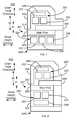
- FIG. 7depicts a side view of an exemplary embodiment of a magnetic recording transducer 200 .
- FIG. 7is not to scale.
- the magnetic transducer 200is analogous to the magnetic transducers 100 , 100 ′, 100 ′′, 100 ′′′ and/or 100 ′′′′. Consequently, analogous components are labeled similarly.
- the magnetic write transducer 200thus includes a write pole 201 having a main pole 202 and auxiliary pole 206 , insulators 204 and 210 , shield 208 and coils 220 and 230 that are analogous to the write pole 101 / 101 ′/ 101 ′′/ 101 ′′′/ 101 ′′′′ having the main pole 102 / 102 ′/ 102 ′′/ 102 ′′′/ 102 ′′′′ and auxiliary pole 106 / 106 ′/ 106 ′′/ 106 ′′′/ 106 ′′′′, the insulator 104 / 104 ′/ 104 ′′/ 104 ′′′/ 104 ′′′′ and 110 / 110 ′/ 110 ′′/ 110 ′′′/ 110 ′′′′, the shield 108 / 108 ′/ 108 ′′/ 108 ′′′/ 108 ′′′′, and the coils 120 / 120 ′/ 120 ′′/ 120 ′′′/ 120 ′′′′ and 130 / 130 ′/ 130 ′′/ 130
- the pole 201may be a PMR pole.
- the transducer 200may be a PMR transducer.
- the pole 201 and transducermay be used in other writers.
- the transducer 200may be an EAMR transducer.
- a read transducermay also be coupled with the write transducer 200 .
- the coils 220 and 230are conductive and carry a write current used to energize the pole.
- the coils 220 and 230may be separate, pancake coils.
- the coils 220 and 230form a single helical coil.
- the insulators 204 and 210may include several different insulators and/or may be formed in multiple fabrication steps.
- the insulator 210is nonmagnetic and insulates the turns 232 , 234 and 238 of the coil 230 .
- the insulator 204 and 210may include aluminum oxide and may be formed using ALD. Thus, the spacing between the turns 232 , 234 , and 238 may be small, for example on the order of 0.25 ⁇ m or less.
- the coils 220 and 230are analogous to the coils shown in FIGS. 2-6 , respectively. However, the coils 220 and 230 include a total of three turns each.
- the coil 220includes turns 222 , 224 and 228 analogous to the turns 122 / 122 ′/ 122 ′′/ 122 ′′′/ 122 ′′′′, 124 / 124 ′/ 124 ′′/ 124 ′′′/ 124 ′′′′, and 128 / 128 ′/ 128 ′′/ 128 ′′′/ 128 ′′′′, respectively.
- the coil 230includes turns 232 , 234 and 238 that are analogous to the turns 132 / 132 ′/ 132 ′′/ 132 ′′′/ 132 ′′′′, 134 / 134 ′/ 134 ′′/ 134 ′′′/ 134 ′′′′ and 138 / 138 ′/ 138 ′′/ 138 ′′′/ 138 ′′′′.
- the turns 222 , 224 , 228 , 232 , 234 and 238may have an analogous configuration and operation to the turns 122 / 122 ′/ 122 ′′/ 122 ′′′/ 122 ′′′′, 124 / 124 ′/ 124 ′′/ 124 ′′′/ 124 ′′′′, 128 / 128 ′/ 128 ′′/ 128 ′′′/ 128 ′′′′, 132 / 132 ′/ 132 ′′/ 132 ′′′/ 132 ′′′′, 134 / 134 ′/ 134 ′′/ 134 ′′′/ 134 ′′′′ and 138 / 138 ′/ 138 ′′/ 138 ′′′/ 138 ′′′′.
- the coil 230has two layers at different distances, d 1 and d 2 , from the pole 201 .
- One layer of the coil 230includes turns 232 and 234 , while the other layer includes turn 238 .
- the turn 238has a height in the down track direction that is less than the length in the stripe height direction.
- the turn 238extends over both of the turns 232 and 234 in the other layer.
- the turn 238extends at least halfway over the turns 232 and 234 .
- the turn 238extends to the edges of the turns 232 and 234 .
- the turns in different layers of the coil 230may have different aspect ratios.
- the cross-sectional area of the turn 238has the substantially the same cross-sectional area as the turns 232 and 234 .
- the coil 220has all turns 222 , 224 and 228 in the same layer.
- the magnetic transducer 200may share the benefits of the magnetic transducers 100 , 100 ′, 100 ′′, 100 ′′′ and 100 ′′′′.
- the magnetic transducer 200may have improved performance at high data rates.
- the coil 230may occupy less space in the stripe height direction.
- the coil 230extends not more than 4.5 ⁇ m in the stripe height direction.
- the coil 230extends not more than 3 ⁇ m in the stripe height direction.
- the length over which the turns 232 and 234 extend in the stripe height directionmay be even further reduced.
- the yokemay be shorter.
- the yoke lengthis not more than 4.5 ⁇ m. In some such embodiments, the yoke length is not more than 3 ⁇ m. The response time of the pole 201 may thus be improved.
- FIG. 8depicts a side view of an exemplary embodiment of a magnetic recording transducer 200 ′.
- FIG. 8is not to scale.
- the magnetic transducer 200 ′is analogous to the magnetic transducer 200 and thus to the transducers 100 , 100 ′, 100 ′′, 100 ′′′ and/or 100 ′′′′. Consequently, analogous components are labeled similarly.
- the magnetic write transducer 200 ′thus includes a write pole 201 ′ having a main pole 202 ′ and auxiliary pole 206 ′, insulators 204 ′ and 210 ′, shield 208 ′ and coils 220 ′ and 230 ′ that are analogous to the write pole 201 having the main pole 202 and auxiliary pole 206 , insulators 204 and 210 , shield 208 and coils 220 and 230 .
- the pole 201 ′may be a PMR pole.
- the transducer 200 ′may be a PMR transducer.
- the pole 201 ′ and transducermay be used in other writers.
- the transducer 200 ′may be an EAMR transducer.
- a read transducermay also be coupled with the write transducer 200 ′.
- the coils 220 ′ and 230 ′are conductive and carry a write current used to energize the pole.
- the coils 220 ′ and 230 ′may be separate, pancake coils.
- the coils 220 ′ and 230 ′form a single helical coil.
- the insulators 204 ′ and 210 ′may include several different insulators and/or may be formed in multiple fabrication steps.
- the insulator 210 ′is nonmagnetic and insulates the turns 232 ′, 234 ′ and 238 ′ of the coil 230 ′.
- the insulator 204 ′ and 210 ′may include aluminum oxide and may be formed using ALD. Thus, the spacing between the turns 232 ′, 234 ′, and 238 ′ may be small, for example on the order of 0.25 ⁇ m or less.
- the coils 220 ′ and 230 ′are analogous to the coils shown in FIGS. 2-7 , respectively. However, the coils 220 ′ and 230 ′ include a total of three turns each.
- the coil 220 ′includes turns 222 ′, 224 ′ and 228 ′ analogous to the turns 122 / 122 ′/ 122 ′′/ 122 ′′′/ 122 ′′′′/ 222 , 124 / 124 ′/ 124 ′′/ 124 ′′′/ 124 ′′′′/ 224 , and 128 / 128 ′/ 128 ′′/ 128 ′′′/ 128 ′′′′/ 228 , respectively.
- the coil 230 ′includes turns 232 ′, 234 ′ and 238 ′ that are analogous to the turns 132 / 132 ′/ 132 ′′/ 132 ′′′/ 132 ′′′′/ 232 , 134 / 134 ′/ 134 ′′/ 134 ′′′/ 134 ′′′′/ 234 and 138 / 138 ′/ 138 ′′′′/ 238 .
- the turns 222 ′, 224 ′, 228 ′, 232 ′, 234 ′ and 238 ′may have an analogous configuration and operation to the turns 222 , 224 , 228 , 232 , 234 and 238 .
- the coil 230 ′has two layers at different distances, d 1 and d 2 , from the pole 201 ′.
- One layer of the coil 230 ′includes turns 232 ′ and 234 ′, while the other layer includes turn 238 ′.
- the turn 238 ′has a height in the down track direction that is less than the length in the stripe height direction.
- the turn 238 ′extends over both of the turns 232 ′ and 234 ′ in the other layer.
- the turn 238 ′extends at least halfway over the turns 232 ′ and 234 ′.
- the turn 238 ′extends to the edges of the turns 232 ′ and 234 ′.
- the turns in different layers of the coil 230 ′may have different aspect ratios.
- the cross-sectional area of the turn 238 ′has the substantially the same cross-sectional area as the turns 232 ′ and 234 ′.
- both coils 220 ′ and 230 ′have turns 228 ′ and 238 ′, respectively, that are wider than they are tall and extend across multiple turns in the other layer
- the magnetic transducer 200 ′may share the benefits of the magnetic transducers 100 , 100 ′, 100 ′′, 100 ′′′, 100 ′′′′, and/or 200 .
- the magnetic transducer 200 ′may have improved performance at high data rates. Because of the configuration of the coil 230 ′, the coil 230 ′ may occupy less space in the stripe height direction. For example, in some embodiments, the coil 230 ′ extends not more than 4.5 ⁇ m in the stripe height direction. In some such embodiments, the coil 230 ′ extends not more than 3 ⁇ m in the stripe height direction.
- the length over which the turns 232 ′ and 234 ′ extend in the stripe height directionmay be even further reduced.
- the yokemay be shorter.
- the yoke lengthis not more than 4.5 ⁇ m. In some such embodiments, the yoke length is not more than 3 ⁇ m. The response time of the pole 201 ′ may thus be improved.
- FIG. 9depicts a side view of an exemplary embodiment of a magnetic recording transducer 200 ′′.
- the magnetic transducer 200 ′′is analogous to the magnetic transducers 200 , 200 ′ and thus to the transducers 100 , 100 ′, 100 ′′, 100 ′′′ and/or 100 ′′′′. Consequently, analogous components are labeled similarly.
- the magnetic write transducer 200 ′′thus includes a write pole 201 ′′ having a main pole 202 ′′ and auxiliary pole 206 ′′, insulators 204 ′′ and 210 ′′, shield 208 ′′ and coils 220 ′′ and 230 ′′ that are analogous to the write pole 201 / 201 ′ having the main pole 202 / 202 ′ and auxiliary pole 206 / 206 ′, insulators 204 / 204 ′ and 210 / 210 ′, shield 208 / 208 ′ and coils 220 / 220 ′ and 230 / 230 ′.
- the pole 201 ′′may be a PMR pole.
- the transducer 200 ′′may be a PMR transducer.
- the pole 201 ′′ and transducermay be used in other writers.
- the transducer 200 ′′may be an EAMR transducer.
- a read transducermay also be coupled with the write transducer 200 ′′.
- the coils 220 ′′ and 230 ′′are conductive and carry a write current used to energize the pole.
- the coils 220 ′′ and 230 ′′may be separate, pancake coils.
- the coils 220 ′′ and 230 ′′form a single helical coil.
- the insulators 204 ′′ and 210 ′′may include several different insulators and/or may be formed in multiple fabrication steps.
- the insulator 210 ′′is nonmagnetic and insulates the turns 232 ′′, 234 ′′ and 238 ′′ of the coil 230 ′′.
- the insulator 204 ′′ and 210 ′′may include aluminum oxide and may be formed using ALD.
- the spacing between the turns 232 ′′, 234 ′′, and 238 ′′may be small, for example on the order of 0.25 ⁇ m or less.
- the coils 220 ′′ and 230 ′′are analogous to the coils shown in FIGS. 2-8 , respectively. However, the coils 220 ′′ and 230 ′′ include a total of three turns each.
- the coil 220 ′′includes turns 222 ′′, 224 ′′ and 228 ′′ analogous to the turns 122 / 122 ′/ 122 ′′/ 122 ′′′/ 122 ′′′′/ 222 / 222 ′, 124 / 124 ′/ 124 ′′/ 124 ′′′/ 124 ′′′′/ 224 / 224 ′, and 128 / 128 ′/ 128 ′′/ 128 ′′′/ 128 ′′′′/ 228 / 228 ′, respectively.
- the coil 230 ′′includes turns 232 ′′, 234 ′′ and 238 ′′ that are analogous to the turns 132 / 132 ′/ 132 ′′/ 132 ′′′/ 132 ′′′′/ 232 / 232 ′′, 134 / 134 ′/ 134 ′′/ 134 ′′′/ 134 ′′′′/ 234 / 234 ′ and 138 / 138 ′/ 138 ′′/ 138 ′′′/ 138 ′′′′/ 238 / 238 ′.
- the turns 222 ′′, 224 ′′, 228 ′′, 232 ′′, 234 ′′ and 238 ′′may have an analogous configuration and operation to the turns 222 / 222 ′, 224 / 224 ′, 228 / 228 ′, 232 / 232 ′, 234 / 234 ′ and 238 / 238 ′.
- the coil 230 ′′has two layers at different distances, d 1 and d 2 , from the pole 201 ′′.
- One layer of the coil 230 ′′includes turns 232 ′′ and 234 ′′, while the other layer includes turn 238 ′′.
- the turn 238 ′′has a height in the down track direction that is less than the length in the stripe height direction.
- the turn 238 ′′extends over both of the turns 232 ′′ and 234 ′′ in the other layer. In some embodiments, the turn 238 ′′ extends at least halfway over the turns 232 ′′ and 234 ′′. In some such embodiments, the turn 238 ′′ extends to the edges of the turns 232 ′′ and 234 ′′. In addition, the turns in different layers of the coil 230 ′′ may have different aspect ratios. In at least some embodiments, the cross-sectional area of the turn 238 ′′ has the substantially the same cross-sectional area as the turns 232 ′′ and 234 ′′.
- both coils 220 ′′ and 230 ′′have turns 228 ′′ and 238 ′′, respectively, that are wider than they are tall and extend across multiple turns in the other layer.
- the turn 238 ′′is closer to the pole 201 ′′ than the turns 232 ′′ and 234 ′′.
- the magnetic transducer 200 ′′may share the benefits of the magnetic transducers 100 , 100 ′, 100 ′′, 100 ′′′, 100 ′′′′, 200 and/or 200 ′.
- the magnetic transducer 200 ′′may have improved performance at high data rates. Because of the configuration of the coil 230 ′′, the coil 230 ′′ may occupy less space in the stripe height direction. For example, in some embodiments, the coil 230 ′′ extends not more than 4.5 ⁇ m in the stripe height direction. In some such embodiments, the coil 230 ′′ extends not more than 3 ⁇ m in the stripe height direction.
- the length over which the turns 232 ′′ and 234 ′′ extend in the stripe height directionmay be even further reduced.
- the yokemay be shorter.
- the yoke lengthis not more than 4.5 ⁇ m.
- the yoke lengthis not more than 3 ⁇ m. The response time of the pole 201 ′′ may thus be improved.
- one or more of the features of the transducers 100 , 100 ′, 100 ′′, 100 ′′′, 100 ′′′′, 200 , 200 ′, and/or 200 ′′may be combined.
- FIG. 10depicts an exemplary embodiment of a method 300 for fabricating a magnetic transducer analogous to the transducers 100 , 100 ′, 100 ′′, 100 ′′′, 100 ′′′′, 200 , 200 ′ and/or 200 ′′.
- the method 300is described in connection with the transducer 100 .
- the method 300may be used to fabricate any of the transducers 100 , 100 ′, 100 ′′, 100 ′′′, 100 ′′′′, 200 , 200 ′ and/or 200 ′′ as well as other analogous transducers.
- the steps of the method 300may be performed in parallel.
- the steps of the method 300may include substeps, may be performed in another order and/or may be interleaved.
- the write pole 101is provided, via step 302 .
- the coils 120 and/or 130are also fabricated, via step 304 .
- Step 304may include various patterning and deposition steps to form the coils 120 and 130 . Further, the steps 302 and 304 are typically interleaved.
- the coil 120is provided before the main pole 102 and auxiliary pole 106 .
- the coil 130is provided after the main pole, but before lapping of the transducer 100 .
- Step 304includes providing the turns 132 , 134 , 136 and 138 of at least the coil 130 in multiple layers.
- Step 204may also include forming the turn(s) such as turn 138 in one layer such that the turn(s) have a height that is smaller than their length.
- the turns 132 , 134 , 136 and 138are insulated in step 304 .
- Thismay include using ALD to deposit aluminum oxide that covers the turns 132 , 134 and 136 and insulates the turns 132 , 134 , and 136 from each other and from the turn 138 .
- the coil 130 , 130 ′, 130 ′′, 130 ′′′, 130 ′′′, 230 , 230 ′ and 230 ′′′may be formed.
- the coil 120 , 120 ′, 120 ′′, 120 ′′′, 120 ′′′, 220 , 220 ′ and 220 ′′may be fabricated in step 304 . Fabrication of the magnetic transducer may then be completed, via step 306 .
- the shield 108may be formed.
- other structure(s)may be formed and the transducer 100 may be lapped to the ABS.
- the magnetic recording transducer 100may be formed.
- the transducers 100 ′, 100 ′′, 100 ′′′, 100 ′′′′, 200 , 200 ′ and 200 ′′may be formed.
- the benefits of one or more of the transducer 100 ′, 100 ′′, 100 ′′′, 100 ′′′′, 200 , 200 ′ and/or 200 ′′may be attained.
Landscapes
- Engineering & Computer Science (AREA)
- Manufacturing & Machinery (AREA)
- Magnetic Heads (AREA)
Abstract
Description
Claims (26)
Priority Applications (1)
| Application Number | Priority Date | Filing Date | Title |
|---|---|---|---|
| US13/532,658US8786983B1 (en) | 2012-06-25 | 2012-06-25 | Magnetic writer having a low aspect ratio two layer coil |
Applications Claiming Priority (1)
| Application Number | Priority Date | Filing Date | Title |
|---|---|---|---|
| US13/532,658US8786983B1 (en) | 2012-06-25 | 2012-06-25 | Magnetic writer having a low aspect ratio two layer coil |
Publications (1)
| Publication Number | Publication Date |
|---|---|
| US8786983B1true US8786983B1 (en) | 2014-07-22 |
Family
ID=51177911
Family Applications (1)
| Application Number | Title | Priority Date | Filing Date |
|---|---|---|---|
| US13/532,658Active2032-07-18US8786983B1 (en) | 2012-06-25 | 2012-06-25 | Magnetic writer having a low aspect ratio two layer coil |
Country Status (1)
| Country | Link |
|---|---|
| US (1) | US8786983B1 (en) |
Cited By (122)
| Publication number | Priority date | Publication date | Assignee | Title |
|---|---|---|---|---|
| US8917581B1 (en) | 2013-12-18 | 2014-12-23 | Western Digital Technologies, Inc. | Self-anneal process for a near field transducer and chimney in a hard disk drive assembly |
| US8947985B1 (en) | 2013-07-16 | 2015-02-03 | Western Digital (Fremont), Llc | Heat assisted magnetic recording transducers having a recessed pole |
| US8953422B1 (en) | 2014-06-10 | 2015-02-10 | Western Digital (Fremont), Llc | Near field transducer using dielectric waveguide core with fine ridge feature |
| US8958272B1 (en) | 2014-06-10 | 2015-02-17 | Western Digital (Fremont), Llc | Interfering near field transducer for energy assisted magnetic recording |
| US8970988B1 (en) | 2013-12-31 | 2015-03-03 | Western Digital (Fremont), Llc | Electric gaps and method for making electric gaps for multiple sensor arrays |
| US8971160B1 (en) | 2013-12-19 | 2015-03-03 | Western Digital (Fremont), Llc | Near field transducer with high refractive index pin for heat assisted magnetic recording |
| US8976635B1 (en) | 2014-06-10 | 2015-03-10 | Western Digital (Fremont), Llc | Near field transducer driven by a transverse electric waveguide for energy assisted magnetic recording |
| US8980109B1 (en) | 2012-12-11 | 2015-03-17 | Western Digital (Fremont), Llc | Method for providing a magnetic recording transducer using a combined main pole and side shield CMP for a wraparound shield scheme |
| US8988812B1 (en) | 2013-11-27 | 2015-03-24 | Western Digital (Fremont), Llc | Multi-sensor array configuration for a two-dimensional magnetic recording (TDMR) operation |
| US8988825B1 (en) | 2014-02-28 | 2015-03-24 | Western Digital (Fremont, LLC | Method for fabricating a magnetic writer having half-side shields |
| US8984740B1 (en) | 2012-11-30 | 2015-03-24 | Western Digital (Fremont), Llc | Process for providing a magnetic recording transducer having a smooth magnetic seed layer |
| US8995087B1 (en) | 2006-11-29 | 2015-03-31 | Western Digital (Fremont), Llc | Perpendicular magnetic recording write head having a wrap around shield |
| US8993217B1 (en) | 2013-04-04 | 2015-03-31 | Western Digital (Fremont), Llc | Double exposure technique for high resolution disk imaging |
| US9001467B1 (en) | 2014-03-05 | 2015-04-07 | Western Digital (Fremont), Llc | Method for fabricating side shields in a magnetic writer |
| US8997832B1 (en) | 2010-11-23 | 2015-04-07 | Western Digital (Fremont), Llc | Method of fabricating micrometer scale components |
| US9007719B1 (en) | 2013-10-23 | 2015-04-14 | Western Digital (Fremont), Llc | Systems and methods for using double mask techniques to achieve very small features |
| US9007725B1 (en) | 2014-10-07 | 2015-04-14 | Western Digital (Fremont), Llc | Sensor with positive coupling between dual ferromagnetic free layer laminates |
| US9007879B1 (en) | 2014-06-10 | 2015-04-14 | Western Digital (Fremont), Llc | Interfering near field transducer having a wide metal bar feature for energy assisted magnetic recording |
| US9013836B1 (en) | 2013-04-02 | 2015-04-21 | Western Digital (Fremont), Llc | Method and system for providing an antiferromagnetically coupled return pole |
| US9042057B1 (en) | 2013-01-09 | 2015-05-26 | Western Digital (Fremont), Llc | Methods for providing magnetic storage elements with high magneto-resistance using Heusler alloys |
| US9042052B1 (en) | 2014-06-23 | 2015-05-26 | Western Digital (Fremont), Llc | Magnetic writer having a partially shunted coil |
| US9042051B2 (en) | 2013-08-15 | 2015-05-26 | Western Digital (Fremont), Llc | Gradient write gap for perpendicular magnetic recording writer |
| US9042058B1 (en) | 2013-10-17 | 2015-05-26 | Western Digital Technologies, Inc. | Shield designed for middle shields in a multiple sensor array |
| US9053735B1 (en) | 2014-06-20 | 2015-06-09 | Western Digital (Fremont), Llc | Method for fabricating a magnetic writer using a full-film metal planarization |
| US9065043B1 (en) | 2012-06-29 | 2015-06-23 | Western Digital (Fremont), Llc | Tunnel magnetoresistance read head with narrow shield-to-shield spacing |
| US9064507B1 (en) | 2009-07-31 | 2015-06-23 | Western Digital (Fremont), Llc | Magnetic etch-stop layer for magnetoresistive read heads |
| US9082428B1 (en) | 2014-08-28 | 2015-07-14 | Seagate Technology Llc | Write head with coil structure aligned with yoke |
| US9082427B1 (en)* | 2014-09-25 | 2015-07-14 | Seagate Technology Llc | Write head having reduced dimensions |
| US9082423B1 (en) | 2013-12-18 | 2015-07-14 | Western Digital (Fremont), Llc | Magnetic recording write transducer having an improved trailing surface profile |
| US9087527B1 (en) | 2014-10-28 | 2015-07-21 | Western Digital (Fremont), Llc | Apparatus and method for middle shield connection in magnetic recording transducers |
| US9087534B1 (en) | 2011-12-20 | 2015-07-21 | Western Digital (Fremont), Llc | Method and system for providing a read transducer having soft and hard magnetic bias structures |
| US9104107B1 (en) | 2013-04-03 | 2015-08-11 | Western Digital (Fremont), Llc | DUV photoresist process |
| US9111564B1 (en) | 2013-04-02 | 2015-08-18 | Western Digital (Fremont), Llc | Magnetic recording writer having a main pole with multiple flare angles |
| US9111550B1 (en) | 2014-12-04 | 2015-08-18 | Western Digital (Fremont), Llc | Write transducer having a magnetic buffer layer spaced between a side shield and a write pole by non-magnetic layers |
| US9111558B1 (en) | 2014-03-14 | 2015-08-18 | Western Digital (Fremont), Llc | System and method of diffractive focusing of light in a waveguide |
| US9123374B1 (en) | 2015-02-12 | 2015-09-01 | Western Digital (Fremont), Llc | Heat assisted magnetic recording writer having an integrated polarization rotation plate |
| US9123358B1 (en) | 2012-06-11 | 2015-09-01 | Western Digital (Fremont), Llc | Conformal high moment side shield seed layer for perpendicular magnetic recording writer |
| US9123362B1 (en) | 2011-03-22 | 2015-09-01 | Western Digital (Fremont), Llc | Methods for assembling an electrically assisted magnetic recording (EAMR) head |
| US9135937B1 (en) | 2014-05-09 | 2015-09-15 | Western Digital (Fremont), Llc | Current modulation on laser diode for energy assisted magnetic recording transducer |
| US9135930B1 (en) | 2014-03-06 | 2015-09-15 | Western Digital (Fremont), Llc | Method for fabricating a magnetic write pole using vacuum deposition |
| US9142233B1 (en) | 2014-02-28 | 2015-09-22 | Western Digital (Fremont), Llc | Heat assisted magnetic recording writer having a recessed pole |
| US9147408B1 (en) | 2013-12-19 | 2015-09-29 | Western Digital (Fremont), Llc | Heated AFM layer deposition and cooling process for TMR magnetic recording sensor with high pinning field |
| US9147404B1 (en) | 2015-03-31 | 2015-09-29 | Western Digital (Fremont), Llc | Method and system for providing a read transducer having a dual free layer |
| US9153255B1 (en) | 2014-03-05 | 2015-10-06 | Western Digital (Fremont), Llc | Method for fabricating a magnetic writer having an asymmetric gap and shields |
| US9159340B1 (en) | 2014-08-28 | 2015-10-13 | Seagate Technology Llc | Coil structure for write head |
| US9183854B2 (en) | 2014-02-24 | 2015-11-10 | Western Digital (Fremont), Llc | Method to make interferometric taper waveguide for HAMR light delivery |
| US9190079B1 (en) | 2014-09-22 | 2015-11-17 | Western Digital (Fremont), Llc | Magnetic write pole having engineered radius of curvature and chisel angle profiles |
| US9190085B1 (en) | 2014-03-12 | 2015-11-17 | Western Digital (Fremont), Llc | Waveguide with reflective grating for localized energy intensity |
| US9196275B1 (en) | 2014-03-12 | 2015-11-24 | Western Digital Technologies, Inc. | Magnetic head separator fin material to prevent particulate contamination on slider |
| US9202480B2 (en) | 2009-10-14 | 2015-12-01 | Western Digital (Fremont), LLC. | Double patterning hard mask for damascene perpendicular magnetic recording (PMR) writer |
| US9202493B1 (en) | 2014-02-28 | 2015-12-01 | Western Digital (Fremont), Llc | Method of making an ultra-sharp tip mode converter for a HAMR head |
| US9214172B2 (en) | 2013-10-23 | 2015-12-15 | Western Digital (Fremont), Llc | Method of manufacturing a magnetic read head |
| US9214165B1 (en) | 2014-12-18 | 2015-12-15 | Western Digital (Fremont), Llc | Magnetic writer having a gradient in saturation magnetization of the shields |
| US9213322B1 (en) | 2012-08-16 | 2015-12-15 | Western Digital (Fremont), Llc | Methods for providing run to run process control using a dynamic tuner |
| US9214169B1 (en) | 2014-06-20 | 2015-12-15 | Western Digital (Fremont), Llc | Magnetic recording read transducer having a laminated free layer |
| US9230570B1 (en) | 2014-08-28 | 2016-01-05 | Seagate Technology Llc | Write head having two yokes |
| US9230565B1 (en) | 2014-06-24 | 2016-01-05 | Western Digital (Fremont), Llc | Magnetic shield for magnetic recording head |
| US9236560B1 (en) | 2014-12-08 | 2016-01-12 | Western Digital (Fremont), Llc | Spin transfer torque tunneling magnetoresistive device having a laminated free layer with perpendicular magnetic anisotropy |
| US9245562B1 (en) | 2015-03-30 | 2016-01-26 | Western Digital (Fremont), Llc | Magnetic recording writer with a composite main pole |
| US9245543B1 (en) | 2010-06-25 | 2016-01-26 | Western Digital (Fremont), Llc | Method for providing an energy assisted magnetic recording head having a laser integrally mounted to the slider |
| US9245545B1 (en) | 2013-04-12 | 2016-01-26 | Wester Digital (Fremont), Llc | Short yoke length coils for magnetic heads in disk drives |
| US9251813B1 (en) | 2009-04-19 | 2016-02-02 | Western Digital (Fremont), Llc | Method of making a magnetic recording head |
| US9263071B1 (en) | 2015-03-31 | 2016-02-16 | Western Digital (Fremont), Llc | Flat NFT for heat assisted magnetic recording |
| US9269382B1 (en) | 2012-06-29 | 2016-02-23 | Western Digital (Fremont), Llc | Method and system for providing a read transducer having improved pinning of the pinned layer at higher recording densities |
| US9280990B1 (en) | 2013-12-11 | 2016-03-08 | Western Digital (Fremont), Llc | Method for fabricating a magnetic writer using multiple etches |
| US9286919B1 (en) | 2014-12-17 | 2016-03-15 | Western Digital (Fremont), Llc | Magnetic writer having a dual side gap |
| US9305583B1 (en) | 2014-02-18 | 2016-04-05 | Western Digital (Fremont), Llc | Method for fabricating a magnetic writer using multiple etches of damascene materials |
| US9312064B1 (en) | 2015-03-02 | 2016-04-12 | Western Digital (Fremont), Llc | Method to fabricate a magnetic head including ion milling of read gap using dual layer hard mask |
| US9318130B1 (en) | 2013-07-02 | 2016-04-19 | Western Digital (Fremont), Llc | Method to fabricate tunneling magnetic recording heads with extended pinned layer |
| US9336814B1 (en) | 2013-03-12 | 2016-05-10 | Western Digital (Fremont), Llc | Inverse tapered waveguide for use in a heat assisted magnetic recording head |
| US9343098B1 (en) | 2013-08-23 | 2016-05-17 | Western Digital (Fremont), Llc | Method for providing a heat assisted magnetic recording transducer having protective pads |
| US9343087B1 (en) | 2014-12-21 | 2016-05-17 | Western Digital (Fremont), Llc | Method for fabricating a magnetic writer having half shields |
| US9349394B1 (en) | 2013-10-18 | 2016-05-24 | Western Digital (Fremont), Llc | Method for fabricating a magnetic writer having a gradient side gap |
| US9349392B1 (en) | 2012-05-24 | 2016-05-24 | Western Digital (Fremont), Llc | Methods for improving adhesion on dielectric substrates |
| US9361913B1 (en) | 2013-06-03 | 2016-06-07 | Western Digital (Fremont), Llc | Recording read heads with a multi-layer AFM layer methods and apparatuses |
| US9361914B1 (en) | 2014-06-18 | 2016-06-07 | Western Digital (Fremont), Llc | Magnetic sensor with thin capping layer |
| US9368134B1 (en) | 2010-12-16 | 2016-06-14 | Western Digital (Fremont), Llc | Method and system for providing an antiferromagnetically coupled writer |
| US9384765B1 (en) | 2015-09-24 | 2016-07-05 | Western Digital (Fremont), Llc | Method and system for providing a HAMR writer having improved optical efficiency |
| US9384763B1 (en) | 2015-03-26 | 2016-07-05 | Western Digital (Fremont), Llc | Dual free layer magnetic reader having a rear bias structure including a soft bias layer |
| US9396743B1 (en) | 2014-02-28 | 2016-07-19 | Western Digital (Fremont), Llc | Systems and methods for controlling soft bias thickness for tunnel magnetoresistance readers |
| US9396742B1 (en) | 2012-11-30 | 2016-07-19 | Western Digital (Fremont), Llc | Magnetoresistive sensor for a magnetic storage system read head, and fabrication method thereof |
| US9406331B1 (en) | 2013-06-17 | 2016-08-02 | Western Digital (Fremont), Llc | Method for making ultra-narrow read sensor and read transducer device resulting therefrom |
| US9424866B1 (en) | 2015-09-24 | 2016-08-23 | Western Digital (Fremont), Llc | Heat assisted magnetic recording write apparatus having a dielectric gap |
| US9431039B1 (en) | 2013-05-21 | 2016-08-30 | Western Digital (Fremont), Llc | Multiple sensor array usable in two-dimensional magnetic recording |
| US9431047B1 (en) | 2013-05-01 | 2016-08-30 | Western Digital (Fremont), Llc | Method for providing an improved AFM reader shield |
| US9431032B1 (en) | 2013-08-14 | 2016-08-30 | Western Digital (Fremont), Llc | Electrical connection arrangement for a multiple sensor array usable in two-dimensional magnetic recording |
| US9431038B1 (en) | 2015-06-29 | 2016-08-30 | Western Digital (Fremont), Llc | Method for fabricating a magnetic write pole having an improved sidewall angle profile |
| US9431031B1 (en) | 2015-03-24 | 2016-08-30 | Western Digital (Fremont), Llc | System and method for magnetic transducers having multiple sensors and AFC shields |
| US9437251B1 (en) | 2014-12-22 | 2016-09-06 | Western Digital (Fremont), Llc | Apparatus and method having TDMR reader to reader shunts |
| US9443541B1 (en) | 2015-03-24 | 2016-09-13 | Western Digital (Fremont), Llc | Magnetic writer having a gradient in saturation magnetization of the shields and return pole |
| US9449621B1 (en) | 2015-03-26 | 2016-09-20 | Western Digital (Fremont), Llc | Dual free layer magnetic reader having a rear bias structure having a high aspect ratio |
| US9449625B1 (en) | 2014-12-24 | 2016-09-20 | Western Digital (Fremont), Llc | Heat assisted magnetic recording head having a plurality of diffusion barrier layers |
| US9472216B1 (en) | 2015-09-23 | 2016-10-18 | Western Digital (Fremont), Llc | Differential dual free layer magnetic reader |
| US9484051B1 (en) | 2015-11-09 | 2016-11-01 | The Provost, Fellows, Foundation Scholars and the other members of Board, of the College of the Holy and Undivided Trinity of Queen Elizabeth near Dublin | Method and system for reducing undesirable reflections in a HAMR write apparatus |
| US9508363B1 (en) | 2014-06-17 | 2016-11-29 | Western Digital (Fremont), Llc | Method for fabricating a magnetic write pole having a leading edge bevel |
| US9508365B1 (en) | 2015-06-24 | 2016-11-29 | Western Digital (Fremont), LLC. | Magnetic reader having a crystal decoupling structure |
| US9508372B1 (en) | 2015-06-03 | 2016-11-29 | Western Digital (Fremont), Llc | Shingle magnetic writer having a low sidewall angle pole |
| US9530443B1 (en) | 2015-06-25 | 2016-12-27 | Western Digital (Fremont), Llc | Method for fabricating a magnetic recording device having a high aspect ratio structure |
| US9564150B1 (en) | 2015-11-24 | 2017-02-07 | Western Digital (Fremont), Llc | Magnetic read apparatus having an improved read sensor isolation circuit |
| US9595273B1 (en) | 2015-09-30 | 2017-03-14 | Western Digital (Fremont), Llc | Shingle magnetic writer having nonconformal shields |
| US9646639B2 (en) | 2015-06-26 | 2017-05-09 | Western Digital (Fremont), Llc | Heat assisted magnetic recording writer having integrated polarization rotation waveguides |
| US9666214B1 (en) | 2015-09-23 | 2017-05-30 | Western Digital (Fremont), Llc | Free layer magnetic reader that may have a reduced shield-to-shield spacing |
| US9697852B2 (en)* | 2015-11-06 | 2017-07-04 | Seagate Technology Llc | Single coil turn data writer |
| US9721591B1 (en)* | 2016-04-12 | 2017-08-01 | Western Digital (Fremont), Llc | Magnetic recording write apparatus having a pole having an aspect ratio greater than one and an auxiliary pole |
| US9721595B1 (en) | 2014-12-04 | 2017-08-01 | Western Digital (Fremont), Llc | Method for providing a storage device |
| US9740805B1 (en) | 2015-12-01 | 2017-08-22 | Western Digital (Fremont), Llc | Method and system for detecting hotspots for photolithographically-defined devices |
| US9741366B1 (en) | 2014-12-18 | 2017-08-22 | Western Digital (Fremont), Llc | Method for fabricating a magnetic writer having a gradient in saturation magnetization of the shields |
| US9754611B1 (en) | 2015-11-30 | 2017-09-05 | Western Digital (Fremont), Llc | Magnetic recording write apparatus having a stepped conformal trailing shield |
| US9767831B1 (en) | 2015-12-01 | 2017-09-19 | Western Digital (Fremont), Llc | Magnetic writer having convex trailing surface pole and conformal write gap |
| US9786301B1 (en) | 2014-12-02 | 2017-10-10 | Western Digital (Fremont), Llc | Apparatuses and methods for providing thin shields in a multiple sensor array |
| US9799351B1 (en) | 2015-11-30 | 2017-10-24 | Western Digital (Fremont), Llc | Short yoke length writer having assist coils |
| US9805742B1 (en) | 2017-02-28 | 2017-10-31 | Seagate Technology Llc | Selective data writer coil |
| US9812155B1 (en) | 2015-11-23 | 2017-11-07 | Western Digital (Fremont), Llc | Method and system for fabricating high junction angle read sensors |
| US9842615B1 (en) | 2015-06-26 | 2017-12-12 | Western Digital (Fremont), Llc | Magnetic reader having a nonmagnetic insertion layer for the pinning layer |
| US9858951B1 (en) | 2015-12-01 | 2018-01-02 | Western Digital (Fremont), Llc | Method for providing a multilayer AFM layer in a read sensor |
| US9881638B1 (en) | 2014-12-17 | 2018-01-30 | Western Digital (Fremont), Llc | Method for providing a near-field transducer (NFT) for a heat assisted magnetic recording (HAMR) device |
| US9934811B1 (en) | 2014-03-07 | 2018-04-03 | Western Digital (Fremont), Llc | Methods for controlling stray fields of magnetic features using magneto-elastic anisotropy |
| US9953670B1 (en) | 2015-11-10 | 2018-04-24 | Western Digital (Fremont), Llc | Method and system for providing a HAMR writer including a multi-mode interference device |
| US10037770B1 (en) | 2015-11-12 | 2018-07-31 | Western Digital (Fremont), Llc | Method for providing a magnetic recording write apparatus having a seamless pole |
| US10074387B1 (en) | 2014-12-21 | 2018-09-11 | Western Digital (Fremont), Llc | Method and system for providing a read transducer having symmetric antiferromagnetically coupled shields |
| US10984828B1 (en) | 2020-06-26 | 2021-04-20 | Western Digital Technologies, Inc. | Sliders with low aspect ratio |
| US11631425B1 (en) | 2022-01-14 | 2023-04-18 | Seagate Technology Llc | Magnetic storage writer with non-uniform coil thickness |
Citations (29)
| Publication number | Priority date | Publication date | Assignee | Title |
|---|---|---|---|---|
| US4639811A (en)* | 1983-12-23 | 1987-01-27 | Siemens Aktiengesellschaft | Combined magnetic write and read head for the vertical magnetization of a corresponding recording medium |
| US4652956A (en)* | 1983-12-23 | 1987-03-24 | Siemens Aktiengesellschaft | Thin-film magnetic head for perpendicular magnetization having a ring shaped magnetic read/write conducting body and write coil winding arranged outside the conducting body |
| US4694368A (en) | 1986-01-10 | 1987-09-15 | Read-Rite Corporation | Thin film magnetic head with three superimposed coils |
| US4703382A (en)* | 1983-12-23 | 1987-10-27 | Siemens Aktiengesellschaft | Thin-film magnetic head for perpendicular (vertical) recording |
| US5173826A (en) | 1991-06-03 | 1992-12-22 | Read-Rite Corp. | Thin film head with coils of varying thickness |
| US5472736A (en) | 1991-06-03 | 1995-12-05 | Read-Rite Corporation | Method of making a bi-level coil for a thin film magnetic transducer |
| US5875080A (en)* | 1997-09-05 | 1999-02-23 | International Business Machines Corporation | Write head with second coil above pole having coil density less electrically connected first coil below the pole |
| US6246541B1 (en) | 1998-05-29 | 2001-06-12 | Hitachi Metals, Ltd. | Thin film magnetic head with reduced magnetic gap by incorporating coil conductors with convex surfaces |
| US6333830B2 (en)* | 1998-11-09 | 2001-12-25 | Read-Rite Corporation | Low resistance coil structure for high speed writer |
| US6349014B1 (en) | 1999-05-14 | 2002-02-19 | Read-Rite Corporation | Magnetic read/write device with insulated coil layer recessed into pole |
| US6525901B1 (en) | 1999-04-02 | 2003-02-25 | Tdk Corporation | Thin film magnetic head and method of manufacturing the same |
| US6654202B2 (en) | 2000-06-20 | 2003-11-25 | Seagate Technology Llc | Disc drive with layered write coil |
| US20040169958A1 (en) | 2003-02-27 | 2004-09-02 | Krounbi Mohamad T. | Thin film recording head with a buried coil providing a shortened yoke and improved dimension control |
| US20050024765A1 (en) | 2003-08-01 | 2005-02-03 | Headway Technologies, Inc. | Method to make a planar writer with low D.C. coil resistance |
| US6861937B1 (en) | 2002-06-25 | 2005-03-01 | Western Digital (Fremont), Inc. | Double winding twin coil for thin-film head writer |
| US20050052771A1 (en) | 2003-09-05 | 2005-03-10 | Seagate Technology Llc | Heat assisted magnetic recording head and method |
| US7116517B1 (en) | 2002-12-18 | 2006-10-03 | Western Digital (Fremont), Inc. | Stitched pole write element with a T-shaped pole tip portion |
| US7126788B1 (en) | 2003-11-26 | 2006-10-24 | Western Digital (Fremont), Inc. | Trailing edge recording magnetic head with reversed double bias coil and deflection pole for perpendicular recording with a non-perpendicular write field |
| US7430098B1 (en)* | 2005-01-18 | 2008-09-30 | Western Digital (Fremont), Llc | Perpendicular magnetic recording head with dynamic flying height heating element |
| US20080316646A1 (en) | 2007-06-25 | 2008-12-25 | Samsung Electronics Co., Ltd. | Perpendicular magnetic recording head and method of manufacturing the same |
| US7573682B2 (en)* | 2005-06-16 | 2009-08-11 | Seagate Technology Llc | Writer heater for thermal protrusion shape control in a magnetic writer |
| US7974046B2 (en)* | 2006-10-18 | 2011-07-05 | Tdk Corporation | Thin-film magnetic head with heating portion and protrusion adjustment portion, head gimbal assembly equipped head, magnetic recording/reproducing apparatus equipped HGA, and manufacturing method of head |
| US8035921B2 (en)* | 2007-07-11 | 2011-10-11 | Samsung Electronics Co., Ltd. | Perpendicular magnetic recording head and method for manufacturing the same |
| US20110273797A1 (en)* | 2010-05-10 | 2011-11-10 | International Business Machines Corporation | Write Head Having a Device for Reducing the Effects of Stray Flux |
| US8218264B1 (en)* | 2010-12-30 | 2012-07-10 | Headway Technologies, Inc. | Magnetic head for perpendicular magnetic recording having a main pole and two shields |
| US8300357B1 (en)* | 2011-12-02 | 2012-10-30 | Headway Technologies, Inc. | Magnetic head for perpendicular magnetic recording having a main pole and a shield |
| US8422166B1 (en)* | 2011-11-28 | 2013-04-16 | Headway Technologies, Inc. | Magnetic head for perpendicular magnetic recording having a main pole and a shield |
| US8514517B1 (en)* | 2011-06-30 | 2013-08-20 | Western Digital (Fremont), Llc | Systems and methods for providing hybrid coils for magnetic write heads |
| US8547659B1 (en)* | 2011-05-09 | 2013-10-01 | Western Digital (Fremont), Llc | System for providing a transducer having a main coil and an additional coil separated from the main pole by a write shield |
- 2012
- 2012-06-25USUS13/532,658patent/US8786983B1/enactiveActive
Patent Citations (33)
| Publication number | Priority date | Publication date | Assignee | Title |
|---|---|---|---|---|
| US4639811A (en)* | 1983-12-23 | 1987-01-27 | Siemens Aktiengesellschaft | Combined magnetic write and read head for the vertical magnetization of a corresponding recording medium |
| US4652956A (en)* | 1983-12-23 | 1987-03-24 | Siemens Aktiengesellschaft | Thin-film magnetic head for perpendicular magnetization having a ring shaped magnetic read/write conducting body and write coil winding arranged outside the conducting body |
| US4703382A (en)* | 1983-12-23 | 1987-10-27 | Siemens Aktiengesellschaft | Thin-film magnetic head for perpendicular (vertical) recording |
| US4694368A (en) | 1986-01-10 | 1987-09-15 | Read-Rite Corporation | Thin film magnetic head with three superimposed coils |
| US5173826A (en) | 1991-06-03 | 1992-12-22 | Read-Rite Corp. | Thin film head with coils of varying thickness |
| US5472736A (en) | 1991-06-03 | 1995-12-05 | Read-Rite Corporation | Method of making a bi-level coil for a thin film magnetic transducer |
| US5875080A (en)* | 1997-09-05 | 1999-02-23 | International Business Machines Corporation | Write head with second coil above pole having coil density less electrically connected first coil below the pole |
| US6246541B1 (en) | 1998-05-29 | 2001-06-12 | Hitachi Metals, Ltd. | Thin film magnetic head with reduced magnetic gap by incorporating coil conductors with convex surfaces |
| US6333830B2 (en)* | 1998-11-09 | 2001-12-25 | Read-Rite Corporation | Low resistance coil structure for high speed writer |
| US6525901B1 (en) | 1999-04-02 | 2003-02-25 | Tdk Corporation | Thin film magnetic head and method of manufacturing the same |
| US6349014B1 (en) | 1999-05-14 | 2002-02-19 | Read-Rite Corporation | Magnetic read/write device with insulated coil layer recessed into pole |
| US6466404B1 (en) | 1999-05-14 | 2002-10-15 | Read-Rite Corporation | Magnetic read/write device with insulated coil layer recessed into pole |
| US6654202B2 (en) | 2000-06-20 | 2003-11-25 | Seagate Technology Llc | Disc drive with layered write coil |
| US6861937B1 (en) | 2002-06-25 | 2005-03-01 | Western Digital (Fremont), Inc. | Double winding twin coil for thin-film head writer |
| US7116517B1 (en) | 2002-12-18 | 2006-10-03 | Western Digital (Fremont), Inc. | Stitched pole write element with a T-shaped pole tip portion |
| US20040169958A1 (en) | 2003-02-27 | 2004-09-02 | Krounbi Mohamad T. | Thin film recording head with a buried coil providing a shortened yoke and improved dimension control |
| US7386933B1 (en) | 2003-02-27 | 2008-06-17 | Western Digital (Fremont), Llc | Method of fabricating thin film write heads with a shortened yoke and improved dimension control |
| US7006327B2 (en) | 2003-02-27 | 2006-02-28 | Western Digital (Fremont), Inc. | Thin film recording head with a buried coil providing a shortened yoke and improved dimension control |
| US20050024765A1 (en) | 2003-08-01 | 2005-02-03 | Headway Technologies, Inc. | Method to make a planar writer with low D.C. coil resistance |
| US20050052771A1 (en) | 2003-09-05 | 2005-03-10 | Seagate Technology Llc | Heat assisted magnetic recording head and method |
| US7126788B1 (en) | 2003-11-26 | 2006-10-24 | Western Digital (Fremont), Inc. | Trailing edge recording magnetic head with reversed double bias coil and deflection pole for perpendicular recording with a non-perpendicular write field |
| US7430098B1 (en)* | 2005-01-18 | 2008-09-30 | Western Digital (Fremont), Llc | Perpendicular magnetic recording head with dynamic flying height heating element |
| US7573682B2 (en)* | 2005-06-16 | 2009-08-11 | Seagate Technology Llc | Writer heater for thermal protrusion shape control in a magnetic writer |
| US7974046B2 (en)* | 2006-10-18 | 2011-07-05 | Tdk Corporation | Thin-film magnetic head with heating portion and protrusion adjustment portion, head gimbal assembly equipped head, magnetic recording/reproducing apparatus equipped HGA, and manufacturing method of head |
| US8035920B2 (en) | 2007-06-25 | 2011-10-11 | Samsung Electronics Co., Ltd. | Perpendicular magnetic recording head having coil portions above a main pole and provided with different cross-sectional shapes and method of manufacturing the same |
| US20080316646A1 (en) | 2007-06-25 | 2008-12-25 | Samsung Electronics Co., Ltd. | Perpendicular magnetic recording head and method of manufacturing the same |
| US8035921B2 (en)* | 2007-07-11 | 2011-10-11 | Samsung Electronics Co., Ltd. | Perpendicular magnetic recording head and method for manufacturing the same |
| US20110273797A1 (en)* | 2010-05-10 | 2011-11-10 | International Business Machines Corporation | Write Head Having a Device for Reducing the Effects of Stray Flux |
| US8218264B1 (en)* | 2010-12-30 | 2012-07-10 | Headway Technologies, Inc. | Magnetic head for perpendicular magnetic recording having a main pole and two shields |
| US8547659B1 (en)* | 2011-05-09 | 2013-10-01 | Western Digital (Fremont), Llc | System for providing a transducer having a main coil and an additional coil separated from the main pole by a write shield |
| US8514517B1 (en)* | 2011-06-30 | 2013-08-20 | Western Digital (Fremont), Llc | Systems and methods for providing hybrid coils for magnetic write heads |
| US8422166B1 (en)* | 2011-11-28 | 2013-04-16 | Headway Technologies, Inc. | Magnetic head for perpendicular magnetic recording having a main pole and a shield |
| US8300357B1 (en)* | 2011-12-02 | 2012-10-30 | Headway Technologies, Inc. | Magnetic head for perpendicular magnetic recording having a main pole and a shield |
Cited By (144)
| Publication number | Priority date | Publication date | Assignee | Title |
|---|---|---|---|---|
| US8995087B1 (en) | 2006-11-29 | 2015-03-31 | Western Digital (Fremont), Llc | Perpendicular magnetic recording write head having a wrap around shield |
| US9251813B1 (en) | 2009-04-19 | 2016-02-02 | Western Digital (Fremont), Llc | Method of making a magnetic recording head |
| US9064507B1 (en) | 2009-07-31 | 2015-06-23 | Western Digital (Fremont), Llc | Magnetic etch-stop layer for magnetoresistive read heads |
| US9202480B2 (en) | 2009-10-14 | 2015-12-01 | Western Digital (Fremont), LLC. | Double patterning hard mask for damascene perpendicular magnetic recording (PMR) writer |
| US9245543B1 (en) | 2010-06-25 | 2016-01-26 | Western Digital (Fremont), Llc | Method for providing an energy assisted magnetic recording head having a laser integrally mounted to the slider |
| US9672847B2 (en) | 2010-11-23 | 2017-06-06 | Western Digital (Fremont), Llc | Micrometer scale components |
| US8997832B1 (en) | 2010-11-23 | 2015-04-07 | Western Digital (Fremont), Llc | Method of fabricating micrometer scale components |
| US9159345B1 (en) | 2010-11-23 | 2015-10-13 | Western Digital (Fremont), Llc | Micrometer scale components |
| US9368134B1 (en) | 2010-12-16 | 2016-06-14 | Western Digital (Fremont), Llc | Method and system for providing an antiferromagnetically coupled writer |
| US9123362B1 (en) | 2011-03-22 | 2015-09-01 | Western Digital (Fremont), Llc | Methods for assembling an electrically assisted magnetic recording (EAMR) head |
| US9087534B1 (en) | 2011-12-20 | 2015-07-21 | Western Digital (Fremont), Llc | Method and system for providing a read transducer having soft and hard magnetic bias structures |
| US9349392B1 (en) | 2012-05-24 | 2016-05-24 | Western Digital (Fremont), Llc | Methods for improving adhesion on dielectric substrates |
| US9940950B2 (en) | 2012-05-24 | 2018-04-10 | Western Digital (Fremont), Llc | Methods for improving adhesion on dielectric substrates |
| US9123358B1 (en) | 2012-06-11 | 2015-09-01 | Western Digital (Fremont), Llc | Conformal high moment side shield seed layer for perpendicular magnetic recording writer |
| US9412400B2 (en) | 2012-06-29 | 2016-08-09 | Western Digital (Fremont), Llc | Tunnel magnetoresistance read head with narrow shield-to-shield spacing |
| US9065043B1 (en) | 2012-06-29 | 2015-06-23 | Western Digital (Fremont), Llc | Tunnel magnetoresistance read head with narrow shield-to-shield spacing |
| US9269382B1 (en) | 2012-06-29 | 2016-02-23 | Western Digital (Fremont), Llc | Method and system for providing a read transducer having improved pinning of the pinned layer at higher recording densities |
| US9213322B1 (en) | 2012-08-16 | 2015-12-15 | Western Digital (Fremont), Llc | Methods for providing run to run process control using a dynamic tuner |
| US9396742B1 (en) | 2012-11-30 | 2016-07-19 | Western Digital (Fremont), Llc | Magnetoresistive sensor for a magnetic storage system read head, and fabrication method thereof |
| US8984740B1 (en) | 2012-11-30 | 2015-03-24 | Western Digital (Fremont), Llc | Process for providing a magnetic recording transducer having a smooth magnetic seed layer |
| US8980109B1 (en) | 2012-12-11 | 2015-03-17 | Western Digital (Fremont), Llc | Method for providing a magnetic recording transducer using a combined main pole and side shield CMP for a wraparound shield scheme |
| US9042057B1 (en) | 2013-01-09 | 2015-05-26 | Western Digital (Fremont), Llc | Methods for providing magnetic storage elements with high magneto-resistance using Heusler alloys |
| US9336814B1 (en) | 2013-03-12 | 2016-05-10 | Western Digital (Fremont), Llc | Inverse tapered waveguide for use in a heat assisted magnetic recording head |
| US9013836B1 (en) | 2013-04-02 | 2015-04-21 | Western Digital (Fremont), Llc | Method and system for providing an antiferromagnetically coupled return pole |
| US9111564B1 (en) | 2013-04-02 | 2015-08-18 | Western Digital (Fremont), Llc | Magnetic recording writer having a main pole with multiple flare angles |
| US9104107B1 (en) | 2013-04-03 | 2015-08-11 | Western Digital (Fremont), Llc | DUV photoresist process |
| US8993217B1 (en) | 2013-04-04 | 2015-03-31 | Western Digital (Fremont), Llc | Double exposure technique for high resolution disk imaging |
| US9245545B1 (en) | 2013-04-12 | 2016-01-26 | Wester Digital (Fremont), Llc | Short yoke length coils for magnetic heads in disk drives |
| US9431047B1 (en) | 2013-05-01 | 2016-08-30 | Western Digital (Fremont), Llc | Method for providing an improved AFM reader shield |
| US9431039B1 (en) | 2013-05-21 | 2016-08-30 | Western Digital (Fremont), Llc | Multiple sensor array usable in two-dimensional magnetic recording |
| US9361913B1 (en) | 2013-06-03 | 2016-06-07 | Western Digital (Fremont), Llc | Recording read heads with a multi-layer AFM layer methods and apparatuses |
| US9406331B1 (en) | 2013-06-17 | 2016-08-02 | Western Digital (Fremont), Llc | Method for making ultra-narrow read sensor and read transducer device resulting therefrom |
| US9318130B1 (en) | 2013-07-02 | 2016-04-19 | Western Digital (Fremont), Llc | Method to fabricate tunneling magnetic recording heads with extended pinned layer |
| US8947985B1 (en) | 2013-07-16 | 2015-02-03 | Western Digital (Fremont), Llc | Heat assisted magnetic recording transducers having a recessed pole |
| US9431032B1 (en) | 2013-08-14 | 2016-08-30 | Western Digital (Fremont), Llc | Electrical connection arrangement for a multiple sensor array usable in two-dimensional magnetic recording |
| US9042051B2 (en) | 2013-08-15 | 2015-05-26 | Western Digital (Fremont), Llc | Gradient write gap for perpendicular magnetic recording writer |
| US9343098B1 (en) | 2013-08-23 | 2016-05-17 | Western Digital (Fremont), Llc | Method for providing a heat assisted magnetic recording transducer having protective pads |
| US9042058B1 (en) | 2013-10-17 | 2015-05-26 | Western Digital Technologies, Inc. | Shield designed for middle shields in a multiple sensor array |
| US9349394B1 (en) | 2013-10-18 | 2016-05-24 | Western Digital (Fremont), Llc | Method for fabricating a magnetic writer having a gradient side gap |
| US9007719B1 (en) | 2013-10-23 | 2015-04-14 | Western Digital (Fremont), Llc | Systems and methods for using double mask techniques to achieve very small features |
| US9830936B2 (en) | 2013-10-23 | 2017-11-28 | Western Digital (Fremont), Llc | Magnetic read head with antiferromagentic layer |
| US9214172B2 (en) | 2013-10-23 | 2015-12-15 | Western Digital (Fremont), Llc | Method of manufacturing a magnetic read head |
| US8988812B1 (en) | 2013-11-27 | 2015-03-24 | Western Digital (Fremont), Llc | Multi-sensor array configuration for a two-dimensional magnetic recording (TDMR) operation |
| US9280990B1 (en) | 2013-12-11 | 2016-03-08 | Western Digital (Fremont), Llc | Method for fabricating a magnetic writer using multiple etches |
| US8917581B1 (en) | 2013-12-18 | 2014-12-23 | Western Digital Technologies, Inc. | Self-anneal process for a near field transducer and chimney in a hard disk drive assembly |
| US9082423B1 (en) | 2013-12-18 | 2015-07-14 | Western Digital (Fremont), Llc | Magnetic recording write transducer having an improved trailing surface profile |
| US9147408B1 (en) | 2013-12-19 | 2015-09-29 | Western Digital (Fremont), Llc | Heated AFM layer deposition and cooling process for TMR magnetic recording sensor with high pinning field |
| US8971160B1 (en) | 2013-12-19 | 2015-03-03 | Western Digital (Fremont), Llc | Near field transducer with high refractive index pin for heat assisted magnetic recording |
| US8970988B1 (en) | 2013-12-31 | 2015-03-03 | Western Digital (Fremont), Llc | Electric gaps and method for making electric gaps for multiple sensor arrays |
| US9305583B1 (en) | 2014-02-18 | 2016-04-05 | Western Digital (Fremont), Llc | Method for fabricating a magnetic writer using multiple etches of damascene materials |
| US9183854B2 (en) | 2014-02-24 | 2015-11-10 | Western Digital (Fremont), Llc | Method to make interferometric taper waveguide for HAMR light delivery |
| US9396743B1 (en) | 2014-02-28 | 2016-07-19 | Western Digital (Fremont), Llc | Systems and methods for controlling soft bias thickness for tunnel magnetoresistance readers |
| US9142233B1 (en) | 2014-02-28 | 2015-09-22 | Western Digital (Fremont), Llc | Heat assisted magnetic recording writer having a recessed pole |
| US9202493B1 (en) | 2014-02-28 | 2015-12-01 | Western Digital (Fremont), Llc | Method of making an ultra-sharp tip mode converter for a HAMR head |
| US8988825B1 (en) | 2014-02-28 | 2015-03-24 | Western Digital (Fremont, LLC | Method for fabricating a magnetic writer having half-side shields |
| US9349393B2 (en) | 2014-03-05 | 2016-05-24 | Western Digital (Fremont), Llc | Magnetic writer having an asymmetric gap and shields |
| US9001467B1 (en) | 2014-03-05 | 2015-04-07 | Western Digital (Fremont), Llc | Method for fabricating side shields in a magnetic writer |
| US9153255B1 (en) | 2014-03-05 | 2015-10-06 | Western Digital (Fremont), Llc | Method for fabricating a magnetic writer having an asymmetric gap and shields |
| US9135930B1 (en) | 2014-03-06 | 2015-09-15 | Western Digital (Fremont), Llc | Method for fabricating a magnetic write pole using vacuum deposition |
| US9934811B1 (en) | 2014-03-07 | 2018-04-03 | Western Digital (Fremont), Llc | Methods for controlling stray fields of magnetic features using magneto-elastic anisotropy |
| US9495984B2 (en) | 2014-03-12 | 2016-11-15 | Western Digital (Fremont), Llc | Waveguide with reflective grating for localized energy intensity |
| US9196275B1 (en) | 2014-03-12 | 2015-11-24 | Western Digital Technologies, Inc. | Magnetic head separator fin material to prevent particulate contamination on slider |
| US9190085B1 (en) | 2014-03-12 | 2015-11-17 | Western Digital (Fremont), Llc | Waveguide with reflective grating for localized energy intensity |
| US9111558B1 (en) | 2014-03-14 | 2015-08-18 | Western Digital (Fremont), Llc | System and method of diffractive focusing of light in a waveguide |
| US9135937B1 (en) | 2014-05-09 | 2015-09-15 | Western Digital (Fremont), Llc | Current modulation on laser diode for energy assisted magnetic recording transducer |
| US9311952B2 (en) | 2014-06-10 | 2016-04-12 | Western Digital (Fremont), Llc | Interfering near field transducer for energy assisted magnetic recording |
| US8953422B1 (en) | 2014-06-10 | 2015-02-10 | Western Digital (Fremont), Llc | Near field transducer using dielectric waveguide core with fine ridge feature |
| US8976635B1 (en) | 2014-06-10 | 2015-03-10 | Western Digital (Fremont), Llc | Near field transducer driven by a transverse electric waveguide for energy assisted magnetic recording |
| US9159346B1 (en) | 2014-06-10 | 2015-10-13 | Western Digital (Fremont), Llc | Near field transducer using dielectric waveguide core with fine ridge feature |
| US8958272B1 (en) | 2014-06-10 | 2015-02-17 | Western Digital (Fremont), Llc | Interfering near field transducer for energy assisted magnetic recording |
| US9007879B1 (en) | 2014-06-10 | 2015-04-14 | Western Digital (Fremont), Llc | Interfering near field transducer having a wide metal bar feature for energy assisted magnetic recording |
| US9508363B1 (en) | 2014-06-17 | 2016-11-29 | Western Digital (Fremont), Llc | Method for fabricating a magnetic write pole having a leading edge bevel |
| US9361914B1 (en) | 2014-06-18 | 2016-06-07 | Western Digital (Fremont), Llc | Magnetic sensor with thin capping layer |
| US9214169B1 (en) | 2014-06-20 | 2015-12-15 | Western Digital (Fremont), Llc | Magnetic recording read transducer having a laminated free layer |
| US9053735B1 (en) | 2014-06-20 | 2015-06-09 | Western Digital (Fremont), Llc | Method for fabricating a magnetic writer using a full-film metal planarization |
| US9042052B1 (en) | 2014-06-23 | 2015-05-26 | Western Digital (Fremont), Llc | Magnetic writer having a partially shunted coil |
| US9230565B1 (en) | 2014-06-24 | 2016-01-05 | Western Digital (Fremont), Llc | Magnetic shield for magnetic recording head |
| US9286918B1 (en) | 2014-08-28 | 2016-03-15 | Seagate Technology Llc | Write head with coil structure aligned with yoke |
| US9230570B1 (en) | 2014-08-28 | 2016-01-05 | Seagate Technology Llc | Write head having two yokes |
| US9159340B1 (en) | 2014-08-28 | 2015-10-13 | Seagate Technology Llc | Coil structure for write head |
| US9082428B1 (en) | 2014-08-28 | 2015-07-14 | Seagate Technology Llc | Write head with coil structure aligned with yoke |
| US9190079B1 (en) | 2014-09-22 | 2015-11-17 | Western Digital (Fremont), Llc | Magnetic write pole having engineered radius of curvature and chisel angle profiles |
| US9082427B1 (en)* | 2014-09-25 | 2015-07-14 | Seagate Technology Llc | Write head having reduced dimensions |
| US9153257B1 (en)* | 2014-09-25 | 2015-10-06 | Seagate Technology Llc | Write head having reduced dimensions |
| US9007725B1 (en) | 2014-10-07 | 2015-04-14 | Western Digital (Fremont), Llc | Sensor with positive coupling between dual ferromagnetic free layer laminates |
| US9087527B1 (en) | 2014-10-28 | 2015-07-21 | Western Digital (Fremont), Llc | Apparatus and method for middle shield connection in magnetic recording transducers |
| US9786301B1 (en) | 2014-12-02 | 2017-10-10 | Western Digital (Fremont), Llc | Apparatuses and methods for providing thin shields in a multiple sensor array |
| US9721595B1 (en) | 2014-12-04 | 2017-08-01 | Western Digital (Fremont), Llc | Method for providing a storage device |
| US9111550B1 (en) | 2014-12-04 | 2015-08-18 | Western Digital (Fremont), Llc | Write transducer having a magnetic buffer layer spaced between a side shield and a write pole by non-magnetic layers |
| US9236560B1 (en) | 2014-12-08 | 2016-01-12 | Western Digital (Fremont), Llc | Spin transfer torque tunneling magnetoresistive device having a laminated free layer with perpendicular magnetic anisotropy |
| US9705072B2 (en) | 2014-12-08 | 2017-07-11 | Western Digital (Fremont), Llc | Spin transfer torque tunneling magnetoresistive device having a laminated free layer with perpendicular magnetic anisotropy |
| US9881638B1 (en) | 2014-12-17 | 2018-01-30 | Western Digital (Fremont), Llc | Method for providing a near-field transducer (NFT) for a heat assisted magnetic recording (HAMR) device |
| US9286919B1 (en) | 2014-12-17 | 2016-03-15 | Western Digital (Fremont), Llc | Magnetic writer having a dual side gap |
| US10553241B2 (en) | 2014-12-17 | 2020-02-04 | Western Digital Technologies, Inc. | Near-field transducer (NFT) for a heat assisted magnetic recording (HAMR) device |
| US9741366B1 (en) | 2014-12-18 | 2017-08-22 | Western Digital (Fremont), Llc | Method for fabricating a magnetic writer having a gradient in saturation magnetization of the shields |
| US9214165B1 (en) | 2014-12-18 | 2015-12-15 | Western Digital (Fremont), Llc | Magnetic writer having a gradient in saturation magnetization of the shields |
| US9343087B1 (en) | 2014-12-21 | 2016-05-17 | Western Digital (Fremont), Llc | Method for fabricating a magnetic writer having half shields |
| US10074387B1 (en) | 2014-12-21 | 2018-09-11 | Western Digital (Fremont), Llc | Method and system for providing a read transducer having symmetric antiferromagnetically coupled shields |
| US9437251B1 (en) | 2014-12-22 | 2016-09-06 | Western Digital (Fremont), Llc | Apparatus and method having TDMR reader to reader shunts |
| US9449625B1 (en) | 2014-12-24 | 2016-09-20 | Western Digital (Fremont), Llc | Heat assisted magnetic recording head having a plurality of diffusion barrier layers |
| US9123374B1 (en) | 2015-02-12 | 2015-09-01 | Western Digital (Fremont), Llc | Heat assisted magnetic recording writer having an integrated polarization rotation plate |
| US9312064B1 (en) | 2015-03-02 | 2016-04-12 | Western Digital (Fremont), Llc | Method to fabricate a magnetic head including ion milling of read gap using dual layer hard mask |
| US9443541B1 (en) | 2015-03-24 | 2016-09-13 | Western Digital (Fremont), Llc | Magnetic writer having a gradient in saturation magnetization of the shields and return pole |
| US9754613B2 (en) | 2015-03-24 | 2017-09-05 | Western Digital (Fremont), Llc | Method for AFC shields for multiple sensor magnetic transducers and magnetic transducers having multiple sensors and AFC shields |
| US9431031B1 (en) | 2015-03-24 | 2016-08-30 | Western Digital (Fremont), Llc | System and method for magnetic transducers having multiple sensors and AFC shields |
| US10115419B2 (en) | 2015-03-24 | 2018-10-30 | Western Digital (Fremont), Llc | Method for AFC shields for multiple sensor magnetic transducers and magnetic transducers having multiple sensors and AFC shields |
| US9922672B1 (en) | 2015-03-26 | 2018-03-20 | Western Digital (Fremont), Llc | Dual free layer magnetic reader having a rear bias structure having a high aspect ratio |
| US9449621B1 (en) | 2015-03-26 | 2016-09-20 | Western Digital (Fremont), Llc | Dual free layer magnetic reader having a rear bias structure having a high aspect ratio |
| US9384763B1 (en) | 2015-03-26 | 2016-07-05 | Western Digital (Fremont), Llc | Dual free layer magnetic reader having a rear bias structure including a soft bias layer |
| US9245562B1 (en) | 2015-03-30 | 2016-01-26 | Western Digital (Fremont), Llc | Magnetic recording writer with a composite main pole |
| US9263071B1 (en) | 2015-03-31 | 2016-02-16 | Western Digital (Fremont), Llc | Flat NFT for heat assisted magnetic recording |
| US9147404B1 (en) | 2015-03-31 | 2015-09-29 | Western Digital (Fremont), Llc | Method and system for providing a read transducer having a dual free layer |
| US9508372B1 (en) | 2015-06-03 | 2016-11-29 | Western Digital (Fremont), Llc | Shingle magnetic writer having a low sidewall angle pole |
| US9508365B1 (en) | 2015-06-24 | 2016-11-29 | Western Digital (Fremont), LLC. | Magnetic reader having a crystal decoupling structure |
| US9530443B1 (en) | 2015-06-25 | 2016-12-27 | Western Digital (Fremont), Llc | Method for fabricating a magnetic recording device having a high aspect ratio structure |
| US9646639B2 (en) | 2015-06-26 | 2017-05-09 | Western Digital (Fremont), Llc | Heat assisted magnetic recording writer having integrated polarization rotation waveguides |
| US10242700B2 (en) | 2015-06-26 | 2019-03-26 | Western Digital (Fremont), Llc | Magnetic reader having a nonmagnetic insertion layer for the pinning layer |
| US10037773B2 (en) | 2015-06-26 | 2018-07-31 | Western Digital (Fremont), Llc | Heat assisted magnetic recording writer having integrated polarization rotation waveguides |
| US9842615B1 (en) | 2015-06-26 | 2017-12-12 | Western Digital (Fremont), Llc | Magnetic reader having a nonmagnetic insertion layer for the pinning layer |
| US9431038B1 (en) | 2015-06-29 | 2016-08-30 | Western Digital (Fremont), Llc | Method for fabricating a magnetic write pole having an improved sidewall angle profile |
| US9666214B1 (en) | 2015-09-23 | 2017-05-30 | Western Digital (Fremont), Llc | Free layer magnetic reader that may have a reduced shield-to-shield spacing |
| US9472216B1 (en) | 2015-09-23 | 2016-10-18 | Western Digital (Fremont), Llc | Differential dual free layer magnetic reader |
| US9384765B1 (en) | 2015-09-24 | 2016-07-05 | Western Digital (Fremont), Llc | Method and system for providing a HAMR writer having improved optical efficiency |
| US9424866B1 (en) | 2015-09-24 | 2016-08-23 | Western Digital (Fremont), Llc | Heat assisted magnetic recording write apparatus having a dielectric gap |
| US9595273B1 (en) | 2015-09-30 | 2017-03-14 | Western Digital (Fremont), Llc | Shingle magnetic writer having nonconformal shields |
| US9697852B2 (en)* | 2015-11-06 | 2017-07-04 | Seagate Technology Llc | Single coil turn data writer |
| US9484051B1 (en) | 2015-11-09 | 2016-11-01 | The Provost, Fellows, Foundation Scholars and the other members of Board, of the College of the Holy and Undivided Trinity of Queen Elizabeth near Dublin | Method and system for reducing undesirable reflections in a HAMR write apparatus |
| US10381029B2 (en) | 2015-11-10 | 2019-08-13 | Western Digital (Fremont), Llc | Method and system for providing a HAMR writer including a multi-mode interference device |
| US9953670B1 (en) | 2015-11-10 | 2018-04-24 | Western Digital (Fremont), Llc | Method and system for providing a HAMR writer including a multi-mode interference device |
| US10037770B1 (en) | 2015-11-12 | 2018-07-31 | Western Digital (Fremont), Llc | Method for providing a magnetic recording write apparatus having a seamless pole |
| US9812155B1 (en) | 2015-11-23 | 2017-11-07 | Western Digital (Fremont), Llc | Method and system for fabricating high junction angle read sensors |
| US9564150B1 (en) | 2015-11-24 | 2017-02-07 | Western Digital (Fremont), Llc | Magnetic read apparatus having an improved read sensor isolation circuit |
| US9754611B1 (en) | 2015-11-30 | 2017-09-05 | Western Digital (Fremont), Llc | Magnetic recording write apparatus having a stepped conformal trailing shield |
| US10121495B2 (en) | 2015-11-30 | 2018-11-06 | Western Digital (Fremont), Llc | Magnetic recording write apparatus having a stepped conformal trailing shield |
| US9799351B1 (en) | 2015-11-30 | 2017-10-24 | Western Digital (Fremont), Llc | Short yoke length writer having assist coils |
| US9997177B2 (en) | 2015-12-01 | 2018-06-12 | Western Digital (Fremont), Llc | Magnetic writer having convex trailing surface pole and conformal write gap |
| US9767831B1 (en) | 2015-12-01 | 2017-09-19 | Western Digital (Fremont), Llc | Magnetic writer having convex trailing surface pole and conformal write gap |
| US9740805B1 (en) | 2015-12-01 | 2017-08-22 | Western Digital (Fremont), Llc | Method and system for detecting hotspots for photolithographically-defined devices |
| US9858951B1 (en) | 2015-12-01 | 2018-01-02 | Western Digital (Fremont), Llc | Method for providing a multilayer AFM layer in a read sensor |
| US9721591B1 (en)* | 2016-04-12 | 2017-08-01 | Western Digital (Fremont), Llc | Magnetic recording write apparatus having a pole having an aspect ratio greater than one and an auxiliary pole |
| US10134428B1 (en) | 2017-02-28 | 2018-11-20 | Seagate Technology Llc | Selective data writer coil |
| US9805742B1 (en) | 2017-02-28 | 2017-10-31 | Seagate Technology Llc | Selective data writer coil |
| US10984828B1 (en) | 2020-06-26 | 2021-04-20 | Western Digital Technologies, Inc. | Sliders with low aspect ratio |
| US11631425B1 (en) | 2022-01-14 | 2023-04-18 | Seagate Technology Llc | Magnetic storage writer with non-uniform coil thickness |
Similar Documents
| Publication | Publication Date | Title |
|---|---|---|
| US8786983B1 (en) | Magnetic writer having a low aspect ratio two layer coil | |
| US8797684B1 (en) | Magnetic writer configured for high data rate recording | |
| US8514517B1 (en) | Systems and methods for providing hybrid coils for magnetic write heads | |
| US8547659B1 (en) | System for providing a transducer having a main coil and an additional coil separated from the main pole by a write shield | |
| US9466319B1 (en) | Perpendicular magnetic recording (PMR) write shield design with minimized wide adjacent track erasure (WATE) | |
| US8405930B1 (en) | Method and system for providing a transducer having dual, ABS recessed auxiliary poles on opposite sides of a main pole with non-magnetic spacer adjoining back portion of main pole and positioned between auxiliary poles | |
| US9361912B1 (en) | High moment side shield design for area density improvement of perpendicular magnetic recording (PMR) writer | |
| US8031433B2 (en) | Method to make an integrated side shield PMR head with non conformal side gap | |
| JP5715750B2 (en) | Thin film magnetic head, method of manufacturing the same, head gimbal assembly, and hard disk drive | |
| US8274758B2 (en) | Composite writer shield for improving writer performance | |
| US8879208B1 (en) | Umbrella shield writer (UmSW) design for perpendicular magnetic recording (PMR) | |
| US20090002885A1 (en) | Perpendicular magnetic recording head and method of manufacturing the same | |
| US8358487B2 (en) | Thin-film magnetic head having coil of varying thinknesses in spaces adjacent the main magnetic pole | |
| US20050024771A1 (en) | Perpendicular recording magnetic head with a write shield magnetically coupled to a first pole piece | |
| US10522178B1 (en) | High damping shield with low magnetic moment in perpendicular magnetic recording (PMR) writer | |
| US9697855B1 (en) | Perpendicular magnetic recording (PMR) write head with multiple layer trailing shield | |
| US9478242B1 (en) | Magnetic recording apparatus having a recessed additional pole segment | |
| US20190279664A1 (en) | Dual Perpendicular Magnetic Recording (PMR) Writer Base Structures and Mirror Imaged Asymmetrical Magnetic Core Shapes for Reduced Writer-Writer Spacing (WWS) | |
| US10916261B1 (en) | True one turn (T1T) perpendicular magnetic recording (PMR) writer designs | |
| US9053715B1 (en) | System for providing a transducer having a split main pole | |
| US6757134B2 (en) | High density thin film inductive head structure having a planarized coil insulation structure including hard baked photoresist and a filler material | |
| US10339964B1 (en) | Perpendicular magnetic recording (PMR) write head with patterned high moment trailing shield | |
| US8988825B1 (en) | Method for fabricating a magnetic writer having half-side shields | |
| US7158344B2 (en) | Thin-film magnetic head having helical coils and manufacturing method for the same | |
| US20060050432A1 (en) | Head design with overlapping coil for narrow pitch tape head |
Legal Events
| Date | Code | Title | Description |
|---|---|---|---|
| AS | Assignment | Owner name:WESTERN DIGITAL (FREMONT), LLC, CALIFORNIA Free format text:ASSIGNMENT OF ASSIGNORS INTEREST;ASSIGNORS:LIU, FENG;LI, ZHANJIE;BAI, ZHIGANG;AND OTHERS;SIGNING DATES FROM 20120727 TO 20120810;REEL/FRAME:028774/0544 | |
| STCF | Information on status: patent grant | Free format text:PATENTED CASE | |
| AS | Assignment | Owner name:JPMORGAN CHASE BANK, N.A., AS COLLATERAL AGENT, IL Free format text:SECURITY AGREEMENT;ASSIGNOR:WESTERN DIGITAL (FREMONT), LLC;REEL/FRAME:038710/0845 Effective date:20160512 Owner name:U.S. BANK NATIONAL ASSOCIATION, AS COLLATERAL AGEN Free format text:SECURITY AGREEMENT;ASSIGNOR:WESTERN DIGITAL (FREMONT), LLC;REEL/FRAME:038744/0675 Effective date:20160512 Owner name:JPMORGAN CHASE BANK, N.A., AS COLLATERAL AGENT, IL Free format text:SECURITY AGREEMENT;ASSIGNOR:WESTERN DIGITAL (FREMONT), LLC;REEL/FRAME:038744/0755 Effective date:20160512 | |
| MAFP | Maintenance fee payment | Free format text:PAYMENT OF MAINTENANCE FEE, 4TH YEAR, LARGE ENTITY (ORIGINAL EVENT CODE: M1551) Year of fee payment:4 | |
| AS | Assignment | Owner name:WESTERN DIGITAL (FREMONT), LLC, CALIFORNIA Free format text:RELEASE BY SECURED PARTY;ASSIGNOR:U.S. BANK NATIONAL ASSOCIATION, AS COLLATERAL AGENT;REEL/FRAME:045501/0158 Effective date:20180227 | |
| AS | Assignment | Owner name:WESTERN DIGITAL TECHNOLOGIES, INC., CALIFORNIA Free format text:ASSIGNMENT OF ASSIGNORS INTEREST;ASSIGNOR:WESTERN DIGITAL (FREMONT), LLC;REEL/FRAME:050450/0582 Effective date:20190508 | |
| MAFP | Maintenance fee payment | Free format text:PAYMENT OF MAINTENANCE FEE, 8TH YEAR, LARGE ENTITY (ORIGINAL EVENT CODE: M1552); ENTITY STATUS OF PATENT OWNER: LARGE ENTITY Year of fee payment:8 | |
| AS | Assignment | Owner name:WESTERN DIGITAL TECHNOLOGIES, INC., CALIFORNIA Free format text:RELEASE OF SECURITY INTEREST AT REEL 038710 FRAME 0845;ASSIGNOR:JPMORGAN CHASE BANK, N.A.;REEL/FRAME:058965/0445 Effective date:20220203 Owner name:WESTERN DIGITAL (FREMONT), LLC, CALIFORNIA Free format text:RELEASE OF SECURITY INTEREST AT REEL 038710 FRAME 0845;ASSIGNOR:JPMORGAN CHASE BANK, N.A.;REEL/FRAME:058965/0445 Effective date:20220203 | |
| AS | Assignment | Owner name:JPMORGAN CHASE BANK, N.A., ILLINOIS Free format text:PATENT COLLATERAL AGREEMENT - A&R LOAN AGREEMENT;ASSIGNOR:WESTERN DIGITAL TECHNOLOGIES, INC.;REEL/FRAME:064715/0001 Effective date:20230818 Owner name:JPMORGAN CHASE BANK, N.A., ILLINOIS Free format text:PATENT COLLATERAL AGREEMENT - DDTL LOAN AGREEMENT;ASSIGNOR:WESTERN DIGITAL TECHNOLOGIES, INC.;REEL/FRAME:067045/0156 Effective date:20230818 |