US8784529B2 - Dehumidifiers having improved heat exchange blocks and associated methods of use and manufacture - Google Patents
Dehumidifiers having improved heat exchange blocks and associated methods of use and manufactureDownload PDFInfo
- Publication number
- US8784529B2 US8784529B2US13/652,423US201213652423AUS8784529B2US 8784529 B2US8784529 B2US 8784529B2US 201213652423 AUS201213652423 AUS 201213652423AUS 8784529 B2US8784529 B2US 8784529B2
- Authority
- US
- United States
- Prior art keywords
- airflow
- heat exchange
- elements
- generally parallel
- notch
- Prior art date
- Legal status (The legal status is an assumption and is not a legal conclusion. Google has not performed a legal analysis and makes no representation as to the accuracy of the status listed.)
- Active
Links
- 238000000034methodMethods0.000titleclaimsabstractdescription13
- 238000004519manufacturing processMethods0.000titleclaimsabstractdescription4
- 125000006850spacer groupChemical group0.000claimsabstractdescription27
- 230000002093peripheral effectEffects0.000claimsabstractdescription13
- 238000004891communicationMethods0.000claimsabstractdescription7
- 239000012530fluidSubstances0.000claimsabstractdescription4
- 238000007789sealingMethods0.000claimsdescription2
- 238000005516engineering processMethods0.000description28
- 239000000463materialSubstances0.000description5
- 230000008569processEffects0.000description4
- 238000005057refrigerationMethods0.000description4
- 239000006260foamSubstances0.000description3
- 239000004033plasticSubstances0.000description3
- 229920003023plasticPolymers0.000description3
- -1polypropylenePolymers0.000description3
- XLYOFNOQVPJJNP-UHFFFAOYSA-NwaterChemical compoundOXLYOFNOQVPJJNP-UHFFFAOYSA-N0.000description3
- PPBRXRYQALVLMV-UHFFFAOYSA-NStyreneChemical compoundC=CC1=CC=CC=C1PPBRXRYQALVLMV-UHFFFAOYSA-N0.000description2
- 230000001154acute effectEffects0.000description2
- 239000000853adhesiveSubstances0.000description2
- 230000001070adhesive effectEffects0.000description2
- 230000000903blocking effectEffects0.000description2
- 229920001971elastomerPolymers0.000description2
- 239000005038ethylene vinyl acetateSubstances0.000description2
- 239000006261foam materialSubstances0.000description2
- 239000004800polyvinyl chlorideSubstances0.000description2
- 239000005060rubberSubstances0.000description2
- 229920002943EPDM rubberPolymers0.000description1
- 239000004831Hot glueSubstances0.000description1
- 239000004743PolypropyleneSubstances0.000description1
- NIXOWILDQLNWCW-UHFFFAOYSA-Nacrylic acid groupChemical groupC(C=C)(=O)ONIXOWILDQLNWCW-UHFFFAOYSA-N0.000description1
- 230000000712assemblyEffects0.000description1
- 238000000429assemblyMethods0.000description1
- DQXBYHZEEUGOBF-UHFFFAOYSA-Nbut-3-enoic acid;etheneChemical compoundC=C.OC(=O)CC=CDQXBYHZEEUGOBF-UHFFFAOYSA-N0.000description1
- 238000001816coolingMethods0.000description1
- 238000001125extrusionMethods0.000description1
- 239000003292glueSubstances0.000description1
- 230000036541healthEffects0.000description1
- 238000010438heat treatmentMethods0.000description1
- 239000007788liquidSubstances0.000description1
- 239000000203mixtureSubstances0.000description1
- 238000012986modificationMethods0.000description1
- 230000004048modificationEffects0.000description1
- 229920001084poly(chloroprene)Polymers0.000description1
- 229920001200poly(ethylene-vinyl acetate)Polymers0.000description1
- 229920001155polypropylenePolymers0.000description1
- 229920000915polyvinyl chloridePolymers0.000description1
- 229920001169thermoplasticPolymers0.000description1
- 229920001187thermosetting polymerPolymers0.000description1
- 239000004416thermosoftening plasticSubstances0.000description1
Images


Classifications
- B—PERFORMING OPERATIONS; TRANSPORTING
- B01—PHYSICAL OR CHEMICAL PROCESSES OR APPARATUS IN GENERAL
- B01D—SEPARATION
- B01D53/00—Separation of gases or vapours; Recovering vapours of volatile solvents from gases; Chemical or biological purification of waste gases, e.g. engine exhaust gases, smoke, fumes, flue gases, aerosols
- B01D53/26—Drying gases or vapours
- B—PERFORMING OPERATIONS; TRANSPORTING
- B01—PHYSICAL OR CHEMICAL PROCESSES OR APPARATUS IN GENERAL
- B01D—SEPARATION
- B01D45/00—Separating dispersed particles from gases or vapours by gravity, inertia, or centrifugal forces
- B01D45/04—Separating dispersed particles from gases or vapours by gravity, inertia, or centrifugal forces by utilising inertia
- B01D45/06—Separating dispersed particles from gases or vapours by gravity, inertia, or centrifugal forces by utilising inertia by reversal of direction of flow
- B—PERFORMING OPERATIONS; TRANSPORTING
- B01—PHYSICAL OR CHEMICAL PROCESSES OR APPARATUS IN GENERAL
- B01D—SEPARATION
- B01D53/00—Separation of gases or vapours; Recovering vapours of volatile solvents from gases; Chemical or biological purification of waste gases, e.g. engine exhaust gases, smoke, fumes, flue gases, aerosols
- B01D53/26—Drying gases or vapours
- B01D53/265—Drying gases or vapours by refrigeration (condensation)
- F—MECHANICAL ENGINEERING; LIGHTING; HEATING; WEAPONS; BLASTING
- F24—HEATING; RANGES; VENTILATING
- F24F—AIR-CONDITIONING; AIR-HUMIDIFICATION; VENTILATION; USE OF AIR CURRENTS FOR SCREENING
- F24F13/00—Details common to, or for air-conditioning, air-humidification, ventilation or use of air currents for screening
- F24F13/08—Air-flow control members, e.g. louvres, grilles, flaps or guide plates
- F24F13/10—Air-flow control members, e.g. louvres, grilles, flaps or guide plates movable, e.g. dampers
- F24F13/14—Air-flow control members, e.g. louvres, grilles, flaps or guide plates movable, e.g. dampers built up of tilting members, e.g. louvre
- F—MECHANICAL ENGINEERING; LIGHTING; HEATING; WEAPONS; BLASTING
- F24—HEATING; RANGES; VENTILATING
- F24F—AIR-CONDITIONING; AIR-HUMIDIFICATION; VENTILATION; USE OF AIR CURRENTS FOR SCREENING
- F24F13/00—Details common to, or for air-conditioning, air-humidification, ventilation or use of air currents for screening
- F24F13/30—Arrangement or mounting of heat-exchangers
- F—MECHANICAL ENGINEERING; LIGHTING; HEATING; WEAPONS; BLASTING
- F24—HEATING; RANGES; VENTILATING
- F24F—AIR-CONDITIONING; AIR-HUMIDIFICATION; VENTILATION; USE OF AIR CURRENTS FOR SCREENING
- F24F3/00—Air-conditioning systems in which conditioned primary air is supplied from one or more central stations to distributing units in the rooms or spaces where it may receive secondary treatment; Apparatus specially designed for such systems
- F24F3/12—Air-conditioning systems in which conditioned primary air is supplied from one or more central stations to distributing units in the rooms or spaces where it may receive secondary treatment; Apparatus specially designed for such systems characterised by the treatment of the air otherwise than by heating and cooling
- F24F3/14—Air-conditioning systems in which conditioned primary air is supplied from one or more central stations to distributing units in the rooms or spaces where it may receive secondary treatment; Apparatus specially designed for such systems characterised by the treatment of the air otherwise than by heating and cooling by humidification; by dehumidification
- F24F3/1405—Air-conditioning systems in which conditioned primary air is supplied from one or more central stations to distributing units in the rooms or spaces where it may receive secondary treatment; Apparatus specially designed for such systems characterised by the treatment of the air otherwise than by heating and cooling by humidification; by dehumidification in which the humidity of the air is exclusively affected by contact with the evaporator of a closed-circuit cooling system or heat pump circuit
- B—PERFORMING OPERATIONS; TRANSPORTING
- B01—PHYSICAL OR CHEMICAL PROCESSES OR APPARATUS IN GENERAL
- B01D—SEPARATION
- B01D2259/00—Type of treatment
- B01D2259/45—Gas separation or purification devices adapted for specific applications
- B01D2259/4508—Gas separation or purification devices adapted for specific applications for cleaning air in buildings
- Y—GENERAL TAGGING OF NEW TECHNOLOGICAL DEVELOPMENTS; GENERAL TAGGING OF CROSS-SECTIONAL TECHNOLOGIES SPANNING OVER SEVERAL SECTIONS OF THE IPC; TECHNICAL SUBJECTS COVERED BY FORMER USPC CROSS-REFERENCE ART COLLECTIONS [XRACs] AND DIGESTS
- Y10—TECHNICAL SUBJECTS COVERED BY FORMER USPC
- Y10T—TECHNICAL SUBJECTS COVERED BY FORMER US CLASSIFICATION
- Y10T29/00—Metal working
- Y10T29/49—Method of mechanical manufacture
- Y10T29/49826—Assembling or joining
Definitions
- FIG. 1Ais a schematic side view of a dehumidifier 100 that is used to describe several features of embodiments of the technology.
- the dehumidifier 100includes a cabinet or housing 102 with an inlet portion 103 and an outlet portion 105 .
- the dehumidifier 100can include a refrigeration cycle including multiple moisture removal devices.
- a representative embodiment of the dehumidifier 100includes an evaporator 106 and a condenser 108 that are each positioned adjacent to a heat exchange block 104 , which is an air-to-air heat exchanger.
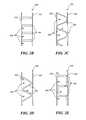
- the first airflow paths 240are at least partially defined between the opposing first and second faces 232 , 234 of neighboring elements 230 , as well as the corresponding spacers 236 , 238 .
- the first airflow path 240can be defined as the portion of the first airflow segment 112 within the heat exchange block 204 .
Landscapes
- Engineering & Computer Science (AREA)
- Chemical & Material Sciences (AREA)
- Combustion & Propulsion (AREA)
- Mechanical Engineering (AREA)
- General Engineering & Computer Science (AREA)
- Chemical Kinetics & Catalysis (AREA)
- Analytical Chemistry (AREA)
- General Chemical & Material Sciences (AREA)
- Oil, Petroleum & Natural Gas (AREA)
- Physics & Mathematics (AREA)
- Thermal Sciences (AREA)
- Drying Of Gases (AREA)
- Heat-Exchange Devices With Radiators And Conduit Assemblies (AREA)
Abstract
Description
Claims (19)
Priority Applications (1)
| Application Number | Priority Date | Filing Date | Title |
|---|---|---|---|
| US13/652,423US8784529B2 (en) | 2011-10-14 | 2012-10-15 | Dehumidifiers having improved heat exchange blocks and associated methods of use and manufacture |
Applications Claiming Priority (2)
| Application Number | Priority Date | Filing Date | Title |
|---|---|---|---|
| US201161547613P | 2011-10-14 | 2011-10-14 | |
| US13/652,423US8784529B2 (en) | 2011-10-14 | 2012-10-15 | Dehumidifiers having improved heat exchange blocks and associated methods of use and manufacture |
Publications (2)
| Publication Number | Publication Date |
|---|---|
| US20130091817A1 US20130091817A1 (en) | 2013-04-18 |
| US8784529B2true US8784529B2 (en) | 2014-07-22 |
Family
ID=48082592
Family Applications (1)
| Application Number | Title | Priority Date | Filing Date |
|---|---|---|---|
| US13/652,423ActiveUS8784529B2 (en) | 2011-10-14 | 2012-10-15 | Dehumidifiers having improved heat exchange blocks and associated methods of use and manufacture |
Country Status (6)
| Country | Link |
|---|---|
| US (1) | US8784529B2 (en) |
| AU (1) | AU2012323876B2 (en) |
| CA (1) | CA2851856C (en) |
| DE (1) | DE112012004290T5 (en) |
| GB (1) | GB2509039B (en) |
| WO (1) | WO2013056260A1 (en) |
Cited By (2)
| Publication number | Priority date | Publication date | Assignee | Title |
|---|---|---|---|---|
| EP3351887A1 (en) | 2017-01-18 | 2018-07-25 | Valmet Technologies Oy | Heat exchange plate and method for manufacturing a heat exchange plate |
| US10060641B2 (en) | 2015-02-25 | 2018-08-28 | Dri-Eaz Products, Inc. | Systems and methods for drying roofs |
Families Citing this family (4)
| Publication number | Priority date | Publication date | Assignee | Title |
|---|---|---|---|---|
| JP2015021676A (en)* | 2013-07-19 | 2015-02-02 | 三菱電機株式会社 | Indoor heat exchanger, indoor equipment, outdoor heat exchanger, outdoor equipment, and air conditioner |
| TWI637131B (en)* | 2017-03-16 | 2018-10-01 | 國立交通大學 | A dehumidification apparatus with enhanced dehumidification effect |
| US11851807B2 (en) | 2019-11-07 | 2023-12-26 | Whirlpool Corporation | Method of removing heat from a clothes tumbling system on the outside of the cabinet |
| CN115540127B (en)* | 2022-09-30 | 2024-12-24 | 青岛海尔空调器有限总公司 | Full heat exchange core, fresh air blower |
Citations (189)
| Publication number | Priority date | Publication date | Assignee | Title |
|---|---|---|---|---|
| US1690108A (en) | 1924-10-30 | 1928-11-06 | Charles B Grady | Heat exchanger |
| US1870457A (en) | 1930-12-19 | 1932-08-09 | Grigsby Grunow Co | Refrigerating apparatus |
| US1894026A (en) | 1929-09-26 | 1933-01-10 | B F Sturtevant Co | Heat exchange apparatus |
| US2093725A (en) | 1934-12-24 | 1937-09-21 | Gen Motors Corp | Refrigerating apparatus |
| US2130092A (en) | 1931-12-30 | 1938-09-13 | Gen Motors Corp | Refrigerating apparatus |
| US2188975A (en) | 1938-04-27 | 1940-02-06 | Borg Warner | Multiple heat exchange unit |
| US2623364A (en) | 1946-09-06 | 1952-12-30 | Munters Carl Georg | Method of and apparatus for removing moisture from the interior of the walls of coldstorage rooms |
| US2719596A (en) | 1950-07-08 | 1955-10-04 | Kent Company Inc | Vacuum cleaner |
| US2758390A (en) | 1951-05-01 | 1956-08-14 | Munters Carl Georg | Dehydrating system for the walls of cold-storage rooms |
| US2886956A (en) | 1954-12-22 | 1959-05-19 | Chrysler Corp | Evaporator unit with condensate collecting means |
| US2905851A (en) | 1957-10-09 | 1959-09-22 | Westinghouse Electric Corp | Single anode rectifier with forced draft air cooling |
| US2932178A (en) | 1958-11-25 | 1960-04-12 | Westinghouse Electric Corp | Air conditioning apparatus |
| US2959400A (en)* | 1957-11-27 | 1960-11-08 | Modine Mfg Co | Prime surface heat exchanger with dimpled sheets |
| US2959036A (en) | 1960-11-08 | R mehalick | ||
| US2975609A (en) | 1955-08-01 | 1961-03-21 | Svenska Flaektfabriken Ab | Air conditioning |
| US3000193A (en) | 1958-02-21 | 1961-09-19 | Hupp Corp | Air conditioning evaporators |
| US3035419A (en) | 1961-01-23 | 1962-05-22 | Westinghouse Electric Corp | Cooling device |
| US3097507A (en) | 1963-07-16 | Adjustable evaporator assemblies for air conditioners | ||
| US3141762A (en) | 1961-01-07 | 1964-07-21 | Elektrokemisk As | Process for transmitting heat from hot fine-grained material to cold finegrained mateial |
| US3149479A (en) | 1961-05-01 | 1964-09-22 | Rudy Mfg Company | Evaporator-condenser unit |
| US3265129A (en)* | 1964-06-26 | 1966-08-09 | United Aircraft Corp | Heat exchanger construction |
| US3621906A (en) | 1969-09-02 | 1971-11-23 | Gen Motors Corp | Control system for heat pipes |
| US3623549A (en) | 1970-08-14 | 1971-11-30 | Smitherm Industries | Heat exchange methods and apparatus |
| GB1311232A (en) | 1970-09-21 | 1973-03-28 | Energiagazdalkodasi Intezet | Heat exchanger |
| US3807493A (en) | 1971-09-28 | 1974-04-30 | Kooltronic Fan Co | Heat exchanger using u-tube heat pipes |
| US3820581A (en) | 1972-02-16 | 1974-06-28 | Ebara Mfg | Multiple effect evaporator apparatus |
| US3866674A (en)* | 1973-10-01 | 1975-02-18 | Gen Electric | Gas turbine regenerator |
| US3877518A (en) | 1971-03-19 | 1975-04-15 | Moshe Y Dreksler | Heat exchange coil |
| US3968833A (en) | 1975-03-18 | 1976-07-13 | Aktiebolaget Svenska Flaktfabriken | Method for heat recovery in ventilation installations |
| US4000779A (en) | 1975-11-28 | 1977-01-04 | General Electric Company | Blowoff baffle |
| US4044820A (en) | 1976-05-24 | 1977-08-30 | Econo-Therm Energy Systems Corporation | Method and apparatus for preheating combustion air while cooling a hot process gas |
| US4091547A (en) | 1976-03-31 | 1978-05-30 | Josglade Limited | Heat recovery means for drying apparatus |
| US4099928A (en)* | 1975-07-18 | 1978-07-11 | Aktiebolaget Carl Munters | Method of manufacturing a heat exchanger body for recuperative exchangers |
| GB2006950A (en) | 1977-10-28 | 1979-05-10 | Kabel Metallwerke Ghh | Device for transporting thermal energy |
| US4176525A (en) | 1977-12-21 | 1979-12-04 | Wylain, Inc. | Combined environmental and refrigeration system |
| US4183399A (en) | 1978-07-19 | 1980-01-15 | Ionics, Inc. | Heat pipe recuperator |
| US4189848A (en) | 1977-08-04 | 1980-02-26 | The United States Of America As Represented By The Department Of Energy | Energy-efficient regenerative liquid desiccant drying process |
| USD254566S (en) | 1978-04-13 | 1980-03-25 | Kemtron Operations Pty. Ltd. | Portable fan housing |
| US4259268A (en) | 1978-12-26 | 1981-03-31 | Diross James | Dual radiator heat exchanger |
| US4280483A (en) | 1980-09-11 | 1981-07-28 | Schaffer I Lawrence | Solar heater |
| US4295342A (en) | 1977-10-27 | 1981-10-20 | James Parro | Heat exchange method using natural flow of heat exchange medium |
| EP0046528A1 (en) | 1980-08-22 | 1982-03-03 | Energiagazdalkodasi Intezet | Heat-engineering apparatus for carrying out thermo-dynamical processes comprising a pair of mutually opposite phase transitions of a work medium |
| US4333517A (en) | 1979-07-10 | 1982-06-08 | James Parro | Heat exchange method using natural flow of heat exchange medium |
| US4428207A (en) | 1981-10-09 | 1984-01-31 | Martin Industries, Inc. | Dehumidifier |
| US4452051A (en) | 1980-08-27 | 1984-06-05 | Commissariat A L'energie Atomique | Modular cold generating apparatus |
| US4502286A (en) | 1982-08-11 | 1985-03-05 | Hitachi, Ltd. | Constant pressure type boiling cooling system |
| US4546820A (en) | 1983-04-01 | 1985-10-15 | Carrier Corporation | Method and apparatus for forming heat exchanger assemblies with bendable tube sheet flanges |
| US4607498A (en) | 1984-05-25 | 1986-08-26 | Dinh Company, Inc. | High efficiency air-conditioner/dehumidifier |
| US4615383A (en) | 1984-05-01 | 1986-10-07 | Sanden Corporation | Serpentine heat exchanging apparatus having corrugated fin units |
| US4628696A (en) | 1982-06-07 | 1986-12-16 | Lord & Sons, Inc. | Heat generating system and method |
| US4724901A (en) | 1980-05-19 | 1988-02-16 | Showa Aluminum Kabushiki Kaisha | Device for releasing heat |
| US4758385A (en)* | 1987-06-22 | 1988-07-19 | Norsaire Systems | Plate for evaporative heat exchanger and evaporative heat exchanger |
| US4761966A (en)* | 1984-10-19 | 1988-08-09 | Walter Stark | Dehumidification and cooling system |
| US4771824A (en) | 1985-03-08 | 1988-09-20 | Institut Francais Du Petrole | Method of transferring heat from a hot fluid A to a cold fluid using a composite fluid as heat carrying agent |
| US4827733A (en) | 1987-10-20 | 1989-05-09 | Dinh Company Inc. | Indirect evaporative cooling system |
| US4921041A (en) | 1987-06-23 | 1990-05-01 | Actronics Kabushiki Kaisha | Structure of a heat pipe |
| USD308414S (en) | 1987-09-21 | 1990-06-05 | Sharp Corporation | Combined dehumidifier and air cleaner |
| US4938035A (en) | 1987-10-20 | 1990-07-03 | Khanh Dinh | Regenerative fresh-air air conditioning system and method |
| US4942740A (en) | 1986-11-24 | 1990-07-24 | Allan Shaw | Air conditioning and method of dehumidifier control |
| USD310412S (en) | 1987-08-18 | 1990-09-04 | Kabushiki Kaisha Toshiba | Dehumidifier |
| CN1046384A (en) | 1990-04-17 | 1990-10-24 | 黄闯芽 | Can improve the evaporimeter of refrigerator performance expansion refrigerator functions |
| US4971137A (en)* | 1989-11-09 | 1990-11-20 | American Energy Exchange, Inc. | Air-to-air heat exchanger with frost preventing means |
| US4971139A (en) | 1990-01-31 | 1990-11-20 | The United States Of America As Represented By The Administrator Of The National Aeronautics And Space Administration | Heat tube device |
| US5031411A (en) | 1990-04-26 | 1991-07-16 | Dec International, Inc. | Efficient dehumidification system |
| US5033539A (en) | 1986-05-13 | 1991-07-23 | Babcock-Hitachi Kabushiki Kaisha | Heat exchanger apparatus |
| US5050109A (en) | 1989-12-19 | 1991-09-17 | The Boeing Company | Method and apparatus for measuring the humidity of ambient air surrounding an aircraft in flight |
| USD325252S (en) | 1990-08-27 | 1992-04-07 | D. Morris Sheet Metal, Inc. | Portable air cleaner unit |
| US5115645A (en) | 1990-11-29 | 1992-05-26 | Wynn's Climate Systems, Inc. | Heat exchanger for refrigerant recovery system |
| US5117651A (en) | 1988-07-26 | 1992-06-02 | Samsung Electronics Co. Ltd. | Dehumidifier |
| US5183106A (en)* | 1992-04-24 | 1993-02-02 | Allied-Signal Inc. | Heat exchange |
| USD333890S (en) | 1989-10-18 | 1993-03-09 | Wap Reinigungssysteme Gmbh & Co. | Vacuum cleaner |
| US5219020A (en) | 1990-11-22 | 1993-06-15 | Actronics Kabushiki Kaisha | Structure of micro-heat pipe |
| USD337592S (en) | 1991-12-12 | 1993-07-20 | Carrier Corporation | Refrigerant reclamation and recycle unit |
| FR2687464A1 (en) | 1992-02-19 | 1993-08-20 | Bernier Jacques | Heat pipes with azeotropic mixture of fluids |
| US5265895A (en) | 1992-06-05 | 1993-11-30 | Barrett Craig G | Floor fan handtruck apparatus and method |
| US5269151A (en) | 1992-04-24 | 1993-12-14 | Heat Pipe Technology, Inc. | Passive defrost system using waste heat |
| USD343706S (en) | 1992-07-08 | 1994-01-25 | U.S. Products, Inc. | High pressure carpet extractor |
| US5301515A (en) | 1991-02-05 | 1994-04-12 | Nippondenso Co., Ltd. | Air conditioning apparatus for automobile |
| US5303561A (en) | 1992-10-14 | 1994-04-19 | Copeland Corporation | Control system for heat pump having humidity responsive variable speed fan |
| US5333470A (en) | 1991-05-09 | 1994-08-02 | Heat Pipe Technology, Inc. | Booster heat pipe for air-conditioning systems |
| US5394040A (en) | 1993-09-07 | 1995-02-28 | Heat Pipe Technology, Inc. | Electric motor having internal heat dissipator |
| US5404938A (en) | 1992-11-17 | 1995-04-11 | Heat Pipe Technology, Inc. | Single assembly heat transfer device |
| USD361178S (en) | 1993-12-09 | 1995-08-08 | Moulinex (Societe Anonyme) | Electric vacuum cleaner |
| US5443624A (en) | 1991-08-30 | 1995-08-22 | Corroventa Avfuktning Ab | Method and apparatus for increasing the yield of an air-drying process |
| USD364947S (en) | 1994-03-18 | 1995-12-05 | Rug Doctor, L.P. | Self contained carpet cleaning machine |
| USD368770S (en) | 1993-11-11 | 1996-04-09 | Ebac Limited | Dehumidifier |
| US5548905A (en) | 1994-04-30 | 1996-08-27 | Kabushiki Kaisha Seibu Giken | Rapid dehydrating and drying method and device usable in low temperature |
| US5564184A (en) | 1994-02-02 | 1996-10-15 | Heat Pipe Technology, Inc. | Method for making heat pipes |
| US5582246A (en) | 1995-02-17 | 1996-12-10 | Heat Pipe Technology, Inc. | Finned tube heat exchanger with secondary star fins and method for its production |
| USD379016S (en) | 1996-01-26 | 1997-04-29 | Wilson Alan E | Wheeled cart |
| US5634353A (en) | 1995-03-02 | 1997-06-03 | Aktiebolaget Electrolux | Air dehumidifier |
| US5649372A (en) | 1996-03-14 | 1997-07-22 | American Dryer Corporation | Drying cycle controller for controlling drying as a function of humidity and temperature |
| US5684672A (en) | 1996-02-20 | 1997-11-04 | International Business Machines Corporation | Laptop computer with an integrated multi-mode antenna |
| US5736647A (en) | 1995-08-07 | 1998-04-07 | Oval Corporation | Vortex flow meter detector and vortex flow meter |
| US5746061A (en) | 1996-09-30 | 1998-05-05 | Kramer; Daniel E. | Physchrometric measurement of air flow through airconditioning evaporator |
| US5749415A (en) | 1997-02-19 | 1998-05-12 | Heat Pipe Technology, Inc. | Roof curb assembly with integral dehumidifier heat pipe controlled by a bypass system |
| USD394499S (en) | 1997-07-19 | 1998-05-19 | Coolant Wizard, Inc. | Portable coolant reconditioning unit |
| USD395492S (en) | 1997-01-24 | 1998-06-23 | Whirlpool Corporation | Dehumidifier |
| US5785723A (en) | 1995-10-23 | 1998-07-28 | Respiratory Support Products | Positive pressure filter system for inflatable blanket heaters |
| US5794453A (en) | 1996-07-22 | 1998-08-18 | Flair Corporation | Apparatus and method for removing condensable material from a gas |
| USD402021S (en) | 1996-12-12 | 1998-12-01 | Honeywell Inc. | Humidifier |
| US5845702A (en) | 1992-06-30 | 1998-12-08 | Heat Pipe Technology, Inc. | Serpentine heat pipe and dehumidification application in air conditioning systems |
| US5890368A (en) | 1996-11-14 | 1999-04-06 | Lakdawala; Ness | Dehumidifier |
| US5901565A (en) | 1997-10-23 | 1999-05-11 | Whirlpool Corporation | Slanted heat exchanger-encased fan-dehumidifier |
| US5913360A (en) | 1995-09-13 | 1999-06-22 | Nautica Dehumidifiers, Inc. | Dual pass cooling plate type cross flow air to air heat exchanger with air flow damper controls |
| US5921315A (en) | 1995-06-07 | 1999-07-13 | Heat Pipe Technology, Inc. | Three-dimensional heat pipe |
| US5950439A (en) | 1997-01-21 | 1999-09-14 | Nartron Corporation | Methods and systems for controlling a refrigeration system |
| US5953926A (en) | 1997-08-05 | 1999-09-21 | Tennessee Valley Authority | Heating, cooling, and dehumidifying system with energy recovery |
| US5953831A (en) | 1997-07-28 | 1999-09-21 | Regentech Limited | Infrared-radiating clothes dryer |
| US5992161A (en) | 1996-07-16 | 1999-11-30 | Ch2Mhill Industrial Design Corporation | Make-up handler with direct expansion dehumidification |
| USD419230S (en) | 1998-08-13 | 2000-01-18 | Adobeair, Inc. | Portable evaporative cooler |
| USD420473S (en) | 1997-07-23 | 2000-02-08 | Shero Deceased William K | Combined portable carpet and upholstery cleaner |
| US6021644A (en) | 1998-08-18 | 2000-02-08 | Ares; Roland | Frosting heat-pump dehumidifier with improved defrost |
| US6030426A (en) | 1998-02-02 | 2000-02-29 | Carrier Corporation | Lifting handle for air purifier |
| US6029464A (en) | 1997-11-07 | 2000-02-29 | Samsung Electronics Co., Ltd. | Dehumidifying apparatus of air conditioner and control method thereof |
| US6035551A (en) | 1993-09-24 | 2000-03-14 | Optimum Air Corporation | Automated air filtration and drying system for waterborne paint and industrial coatings |
| USD422386S (en) | 1998-07-16 | 2000-04-04 | Pullman-Holt Corporation | Vacuum cleaner |
| USD422351S (en) | 1999-03-29 | 2000-04-04 | Shop Vac Corporation | Blower |
| USD426473S (en) | 1999-09-09 | 2000-06-13 | Dri-Eaz Products, Inc. | Moisture detector |
| US6101815A (en) | 1998-11-09 | 2000-08-15 | General Electric Company | Thermo-electrical dehumidifier |
| US6105278A (en) | 1995-09-15 | 2000-08-22 | Microwave Drying Limited | Method and apparatus for drying timber |
| US6182747B1 (en)* | 1995-09-13 | 2001-02-06 | Nautica Dehumidifiers, Inc. | Plate-type crossflow air-to-air heat-exchanger comprising side-by-side-multiple small-plates |
| USD441161S1 (en) | 2000-05-23 | 2001-04-24 | Thomas H. Shetterly | Tool caddy |
| US6223543B1 (en) | 1999-06-17 | 2001-05-01 | Heat-Timer Corporation | Effective temperature controller and method of effective temperature control |
| US6237352B1 (en) | 1999-08-18 | 2001-05-29 | Winton J. Goodchild | Water producing and dispensing machine |
| USD445116S1 (en) | 1999-10-29 | 2001-07-17 | Spx Corporation | Portable recovery cabinet |
| USD446612S1 (en) | 1999-03-19 | 2001-08-14 | Rowenta-Werke Gmbh | Combined wet/dry vacuum cleaner |
| US20010045098A1 (en) | 2000-02-15 | 2001-11-29 | Derryberry Andy Lynn | Method and apparatus for de-icing humidifier |
| USD453560S1 (en) | 2000-05-08 | 2002-02-12 | American Biosystems, Inc. | Air flow generator |
| US6447586B1 (en) | 2000-12-06 | 2002-09-10 | Whirlpool Corporation | Air treatment appliance with a translucent body |
| US6463794B1 (en) | 2000-04-10 | 2002-10-15 | Malcam Ltd. | Method and device for non-invasively determining moisture content and uniformity of solid plant matter during on-line drying or cooling forced-air treatment |
| USD465018S1 (en) | 2001-03-04 | 2002-10-29 | Fumex Ab | Mobile filter unit |
| US6478855B1 (en) | 1999-08-30 | 2002-11-12 | Seibu Giken Co., Ltd. | Method of dehumidifying and dehumidifier with heat exchanger having first and second passages and moisture cooling in the second passages |
| US20030034573A1 (en) | 2001-08-14 | 2003-02-20 | Hamilton Beach/Proctor-Silex, Inc. | Humidifier filter servicing and water level indicator |
| US6542062B1 (en) | 1999-06-11 | 2003-04-01 | Tecumseh Products Company | Overload protector with control element |
| USD480467S1 (en) | 2002-09-25 | 2003-10-07 | Dri-Eaz Products, Inc. | Air mover |
| USD482171S1 (en) | 2002-12-13 | 2003-11-11 | One World Technologies Limited | Drill container |
| US6644060B1 (en) | 2000-02-21 | 2003-11-11 | Dil Sham Ventures | Apparatus for extracting potable water from the environment air |
| US6796896B2 (en) | 2002-09-19 | 2004-09-28 | Peter J. Laiti | Environmental control unit, and air handling systems and methods using same |
| USD500848S1 (en) | 2003-09-25 | 2005-01-11 | Homedics, Inc. | Air cleaner |
| US20050011255A1 (en) | 2003-07-16 | 2005-01-20 | Weisenberger Andrew R. | Building moisture content certification system and method |
| US20050011962A1 (en) | 2003-07-16 | 2005-01-20 | Weisenberger Andrew R. | Moisture reduction and mold and moisture damage preventative system and method in construction |
| US20050066538A1 (en) | 2003-09-29 | 2005-03-31 | Michael Goldberg | Heat pump clothes dryer |
| US6895774B1 (en) | 2004-05-25 | 2005-05-24 | Roland Ares | Refrigerated air drier with dehumidification of both the low pressure and the high pressure air |
| USD508735S1 (en) | 2004-05-13 | 2005-08-23 | Dri-Eaz Products, Inc. | Dehumidifier |
| US20050183430A1 (en) | 2003-06-24 | 2005-08-25 | Mcmillan Robert B. | Microprocessor controlled evaporative cooler |
| US6941763B2 (en) | 1999-11-19 | 2005-09-13 | Ebara Corporation | Heat pump and dehumidifying apparatus |
| US20050218535A1 (en) | 2002-08-05 | 2005-10-06 | Valeriy Maisotsenko | Indirect evaporative cooling mechanism |
| US20050235673A1 (en)* | 2002-07-24 | 2005-10-27 | Takahisa Sueoka | Dehumidification element |
| USD515190S1 (en) | 2004-09-28 | 2006-02-14 | Dri-Eaz Products, Inc. | Air filtration system |
| US20060086125A1 (en)* | 2002-07-22 | 2006-04-27 | Takahisa Sueoka | Dehumidifying element, and adsorbing element used for the dehumidifying element |
| USD529019S1 (en) | 2005-04-19 | 2006-09-26 | Samsung Electronics Co., Ltd. | Home theater |
| US20060214315A1 (en) | 2005-03-25 | 2006-09-28 | Emerson Electric Co | Humidifier device and method of operation |
| US20060260790A1 (en)* | 2005-05-18 | 2006-11-23 | Mark Theno | Heat exchanger core |
| US20070012060A1 (en) | 2005-07-13 | 2007-01-18 | Everett Simons | Refrigeration cycle dehumidifier |
| JP2007054700A (en) | 2005-08-23 | 2007-03-08 | Matsushita Electric Ind Co Ltd | Dehumidifier |
| US7194870B1 (en) | 2005-11-16 | 2007-03-27 | Bou-Matic Technologies Llc | High performance dehumidifier |
| US20070107450A1 (en) | 2005-11-16 | 2007-05-17 | Keiji Sasao | Air conditioning apparatus |
| US7228693B2 (en) | 2004-01-12 | 2007-06-12 | American Standard International Inc. | Controlling airflow in an air conditioning system for control of system discharge temperature and humidity |
| US7246503B1 (en) | 2005-11-16 | 2007-07-24 | Bou-Matic Technologies Llc | Enhanced drying dehumidifier |
| US7281389B1 (en) | 2005-11-16 | 2007-10-16 | Bou-Matic Technologies Llc | Enhanced performance dehumidifier |
| USD565269S1 (en) | 2007-03-28 | 2008-03-25 | Emerson Electric Co. | Cart with a vacuum cleaner |
| WO2008057647A2 (en) | 2006-11-07 | 2008-05-15 | Tiax Llc. | Dehumidification |
| USD572356S1 (en) | 2007-02-01 | 2008-07-01 | Abatement Technologies, Inc. | Air filtration device |
| US20080202131A1 (en) | 2005-05-26 | 2008-08-28 | Chaim Brody | System and Method for Controlling Defrost Cycles of a Refrigeration Device |
| US20080223050A1 (en) | 2007-03-13 | 2008-09-18 | Dri-Eaz Products, Inc. | Dehumidification systems and methods for extracting moisture from water damaged structures |
| USD577426S1 (en) | 2007-11-19 | 2008-09-23 | Wu Li Agriculture Machine Co., Ltd. | Misting fan |
| USD581111S1 (en) | 2007-10-12 | 2008-11-18 | Black & Decker Inc. | Vacuum |
| USD581608S1 (en) | 2006-07-06 | 2008-11-25 | Alfred Kaercher Gmbh & Co. Kg | Vacuum cleaner |
| US20090007367A1 (en) | 2007-07-06 | 2009-01-08 | Archbold Tony | Attachment device |
| US20090101727A1 (en) | 2007-09-14 | 2009-04-23 | Air Tech Equipment Ltd. | Dehumidifying system |
| US20090165485A1 (en)* | 2007-12-27 | 2009-07-02 | Walter Stark | Hybrid dehumidification system for applications with high internally-generated moisture loads |
| USD612032S1 (en) | 2008-02-26 | 2010-03-16 | Champion Cooler Corporation | Enclosure of an evaporative cooler |
| US20100125367A1 (en) | 2008-11-17 | 2010-05-20 | Dri-Eaz Products, Inc. | Methods and systems for determining dehumidifier performance |
| USD617437S1 (en) | 2009-11-04 | 2010-06-08 | Hakko Corporation | Air cleaner |
| US20100224565A1 (en)* | 2009-03-06 | 2010-09-09 | Dunne Stephen R | Multiple bed temperature controlled adsorption |
| US20100269526A1 (en) | 2009-04-27 | 2010-10-28 | Robert Pendergrass | Systems and methods for operating and monitoring dehumidifiers |
| US7856840B2 (en) | 2005-06-15 | 2010-12-28 | Lg Electronics Inc. | Dehumidifier |
| USD634414S1 (en) | 2010-04-27 | 2011-03-15 | Dri-Eaz Products, Inc. | Dehumidifier housing |
| US20110061408A1 (en) | 2009-09-11 | 2011-03-17 | Tom Schnelle | Dehumidifiers for high temperature operation, and associated systems and methods |
| US20110073290A1 (en) | 2009-09-30 | 2011-03-31 | Young Soo Chang | Heat exchanger for dehumidifier using liquid desiccant and dehumidifier using liquid desiccant having the same |
| USD641845S1 (en) | 2010-08-10 | 2011-07-19 | Port-A-Cool, Llc | Evaporative cooler housing |
| USD641844S1 (en) | 2010-08-09 | 2011-07-19 | Port-A-Cool, Llc | Evaporative cooler housing |
| US8056182B2 (en) | 2005-08-30 | 2011-11-15 | Tacony Corporation | Heating system for a portable carpet extractor |
| US8091868B2 (en)* | 2008-07-23 | 2012-01-10 | GM Global Technology Operations LLC | WVT design for reduced mass and improved sealing reliability |
| US8127397B2 (en) | 2008-04-30 | 2012-03-06 | Alfred Kaercher Gmbh & Co. Kg | Vacuum cleaner |
| US8227648B2 (en)* | 2008-12-17 | 2012-07-24 | Uop Llc | Combined temperature controlled water adsorption and two stage heat pump process for fuel ethanol dehydration |
| US20130047662A1 (en) | 2011-08-31 | 2013-02-28 | Dri-Eaz Products, Inc. | Dehumidifiers with improved fluid management and associated methods of use and manufacture |
| USD678494S1 (en) | 2011-08-31 | 2013-03-19 | Dri-Eaz Products, Inc. | Dehumidifier housing |
- 2012
- 2012-10-15WOPCT/US2012/060310patent/WO2013056260A1/enactiveApplication Filing
- 2012-10-15DEDE112012004290.5Tpatent/DE112012004290T5/ennot_activeWithdrawn
- 2012-10-15AUAU2012323876Apatent/AU2012323876B2/ennot_activeCeased
- 2012-10-15GBGB1406557.7Apatent/GB2509039B/enactiveActive
- 2012-10-15USUS13/652,423patent/US8784529B2/enactiveActive
- 2012-10-15CACA2851856Apatent/CA2851856C/ennot_activeExpired - Fee Related
Patent Citations (193)
| Publication number | Priority date | Publication date | Assignee | Title |
|---|---|---|---|---|
| US2959036A (en) | 1960-11-08 | R mehalick | ||
| US3097507A (en) | 1963-07-16 | Adjustable evaporator assemblies for air conditioners | ||
| US1690108A (en) | 1924-10-30 | 1928-11-06 | Charles B Grady | Heat exchanger |
| US1894026A (en) | 1929-09-26 | 1933-01-10 | B F Sturtevant Co | Heat exchange apparatus |
| US1870457A (en) | 1930-12-19 | 1932-08-09 | Grigsby Grunow Co | Refrigerating apparatus |
| US2130092A (en) | 1931-12-30 | 1938-09-13 | Gen Motors Corp | Refrigerating apparatus |
| US2093725A (en) | 1934-12-24 | 1937-09-21 | Gen Motors Corp | Refrigerating apparatus |
| US2188975A (en) | 1938-04-27 | 1940-02-06 | Borg Warner | Multiple heat exchange unit |
| US2623364A (en) | 1946-09-06 | 1952-12-30 | Munters Carl Georg | Method of and apparatus for removing moisture from the interior of the walls of coldstorage rooms |
| US2719596A (en) | 1950-07-08 | 1955-10-04 | Kent Company Inc | Vacuum cleaner |
| US2758390A (en) | 1951-05-01 | 1956-08-14 | Munters Carl Georg | Dehydrating system for the walls of cold-storage rooms |
| US2886956A (en) | 1954-12-22 | 1959-05-19 | Chrysler Corp | Evaporator unit with condensate collecting means |
| US2975609A (en) | 1955-08-01 | 1961-03-21 | Svenska Flaektfabriken Ab | Air conditioning |
| US2905851A (en) | 1957-10-09 | 1959-09-22 | Westinghouse Electric Corp | Single anode rectifier with forced draft air cooling |
| US2959400A (en)* | 1957-11-27 | 1960-11-08 | Modine Mfg Co | Prime surface heat exchanger with dimpled sheets |
| US3000193A (en) | 1958-02-21 | 1961-09-19 | Hupp Corp | Air conditioning evaporators |
| US2932178A (en) | 1958-11-25 | 1960-04-12 | Westinghouse Electric Corp | Air conditioning apparatus |
| US3141762A (en) | 1961-01-07 | 1964-07-21 | Elektrokemisk As | Process for transmitting heat from hot fine-grained material to cold finegrained mateial |
| US3035419A (en) | 1961-01-23 | 1962-05-22 | Westinghouse Electric Corp | Cooling device |
| US3149479A (en) | 1961-05-01 | 1964-09-22 | Rudy Mfg Company | Evaporator-condenser unit |
| US3265129A (en)* | 1964-06-26 | 1966-08-09 | United Aircraft Corp | Heat exchanger construction |
| US3621906A (en) | 1969-09-02 | 1971-11-23 | Gen Motors Corp | Control system for heat pipes |
| US3623549A (en) | 1970-08-14 | 1971-11-30 | Smitherm Industries | Heat exchange methods and apparatus |
| GB1311232A (en) | 1970-09-21 | 1973-03-28 | Energiagazdalkodasi Intezet | Heat exchanger |
| US3877518A (en) | 1971-03-19 | 1975-04-15 | Moshe Y Dreksler | Heat exchange coil |
| US3807493A (en) | 1971-09-28 | 1974-04-30 | Kooltronic Fan Co | Heat exchanger using u-tube heat pipes |
| US3820581A (en) | 1972-02-16 | 1974-06-28 | Ebara Mfg | Multiple effect evaporator apparatus |
| US3866674A (en)* | 1973-10-01 | 1975-02-18 | Gen Electric | Gas turbine regenerator |
| US3968833A (en) | 1975-03-18 | 1976-07-13 | Aktiebolaget Svenska Flaktfabriken | Method for heat recovery in ventilation installations |
| US4099928A (en)* | 1975-07-18 | 1978-07-11 | Aktiebolaget Carl Munters | Method of manufacturing a heat exchanger body for recuperative exchangers |
| US4000779A (en) | 1975-11-28 | 1977-01-04 | General Electric Company | Blowoff baffle |
| US4091547A (en) | 1976-03-31 | 1978-05-30 | Josglade Limited | Heat recovery means for drying apparatus |
| US4044820A (en) | 1976-05-24 | 1977-08-30 | Econo-Therm Energy Systems Corporation | Method and apparatus for preheating combustion air while cooling a hot process gas |
| US4189848A (en) | 1977-08-04 | 1980-02-26 | The United States Of America As Represented By The Department Of Energy | Energy-efficient regenerative liquid desiccant drying process |
| US4295342A (en) | 1977-10-27 | 1981-10-20 | James Parro | Heat exchange method using natural flow of heat exchange medium |
| GB2006950A (en) | 1977-10-28 | 1979-05-10 | Kabel Metallwerke Ghh | Device for transporting thermal energy |
| US4176525A (en) | 1977-12-21 | 1979-12-04 | Wylain, Inc. | Combined environmental and refrigeration system |
| USD254566S (en) | 1978-04-13 | 1980-03-25 | Kemtron Operations Pty. Ltd. | Portable fan housing |
| US4183399A (en) | 1978-07-19 | 1980-01-15 | Ionics, Inc. | Heat pipe recuperator |
| US4259268A (en) | 1978-12-26 | 1981-03-31 | Diross James | Dual radiator heat exchanger |
| US4333517A (en) | 1979-07-10 | 1982-06-08 | James Parro | Heat exchange method using natural flow of heat exchange medium |
| US4724901A (en) | 1980-05-19 | 1988-02-16 | Showa Aluminum Kabushiki Kaisha | Device for releasing heat |
| EP0046528A1 (en) | 1980-08-22 | 1982-03-03 | Energiagazdalkodasi Intezet | Heat-engineering apparatus for carrying out thermo-dynamical processes comprising a pair of mutually opposite phase transitions of a work medium |
| US4452051A (en) | 1980-08-27 | 1984-06-05 | Commissariat A L'energie Atomique | Modular cold generating apparatus |
| US4280483A (en) | 1980-09-11 | 1981-07-28 | Schaffer I Lawrence | Solar heater |
| US4428207A (en) | 1981-10-09 | 1984-01-31 | Martin Industries, Inc. | Dehumidifier |
| US4628696A (en) | 1982-06-07 | 1986-12-16 | Lord & Sons, Inc. | Heat generating system and method |
| US4502286A (en) | 1982-08-11 | 1985-03-05 | Hitachi, Ltd. | Constant pressure type boiling cooling system |
| US4546820A (en) | 1983-04-01 | 1985-10-15 | Carrier Corporation | Method and apparatus for forming heat exchanger assemblies with bendable tube sheet flanges |
| US4615383A (en) | 1984-05-01 | 1986-10-07 | Sanden Corporation | Serpentine heat exchanging apparatus having corrugated fin units |
| US4607498A (en) | 1984-05-25 | 1986-08-26 | Dinh Company, Inc. | High efficiency air-conditioner/dehumidifier |
| US4761966A (en)* | 1984-10-19 | 1988-08-09 | Walter Stark | Dehumidification and cooling system |
| US4771824A (en) | 1985-03-08 | 1988-09-20 | Institut Francais Du Petrole | Method of transferring heat from a hot fluid A to a cold fluid using a composite fluid as heat carrying agent |
| US5033539A (en) | 1986-05-13 | 1991-07-23 | Babcock-Hitachi Kabushiki Kaisha | Heat exchanger apparatus |
| US4942740A (en) | 1986-11-24 | 1990-07-24 | Allan Shaw | Air conditioning and method of dehumidifier control |
| US4758385A (en)* | 1987-06-22 | 1988-07-19 | Norsaire Systems | Plate for evaporative heat exchanger and evaporative heat exchanger |
| US4921041A (en) | 1987-06-23 | 1990-05-01 | Actronics Kabushiki Kaisha | Structure of a heat pipe |
| USD310412S (en) | 1987-08-18 | 1990-09-04 | Kabushiki Kaisha Toshiba | Dehumidifier |
| USD308414S (en) | 1987-09-21 | 1990-06-05 | Sharp Corporation | Combined dehumidifier and air cleaner |
| US4827733A (en) | 1987-10-20 | 1989-05-09 | Dinh Company Inc. | Indirect evaporative cooling system |
| US4938035A (en) | 1987-10-20 | 1990-07-03 | Khanh Dinh | Regenerative fresh-air air conditioning system and method |
| US5117651A (en) | 1988-07-26 | 1992-06-02 | Samsung Electronics Co. Ltd. | Dehumidifier |
| USD333890S (en) | 1989-10-18 | 1993-03-09 | Wap Reinigungssysteme Gmbh & Co. | Vacuum cleaner |
| USD334258S (en) | 1989-10-18 | 1993-03-23 | Wap Reinigungssysteme Gmbh & Co. | Vacuum cleaner |
| US4971137A (en)* | 1989-11-09 | 1990-11-20 | American Energy Exchange, Inc. | Air-to-air heat exchanger with frost preventing means |
| US5050109A (en) | 1989-12-19 | 1991-09-17 | The Boeing Company | Method and apparatus for measuring the humidity of ambient air surrounding an aircraft in flight |
| US4971139A (en) | 1990-01-31 | 1990-11-20 | The United States Of America As Represented By The Administrator Of The National Aeronautics And Space Administration | Heat tube device |
| CN1046384A (en) | 1990-04-17 | 1990-10-24 | 黄闯芽 | Can improve the evaporimeter of refrigerator performance expansion refrigerator functions |
| US5031411A (en) | 1990-04-26 | 1991-07-16 | Dec International, Inc. | Efficient dehumidification system |
| USD325252S (en) | 1990-08-27 | 1992-04-07 | D. Morris Sheet Metal, Inc. | Portable air cleaner unit |
| US5219020A (en) | 1990-11-22 | 1993-06-15 | Actronics Kabushiki Kaisha | Structure of micro-heat pipe |
| US5115645A (en) | 1990-11-29 | 1992-05-26 | Wynn's Climate Systems, Inc. | Heat exchanger for refrigerant recovery system |
| US5301515A (en) | 1991-02-05 | 1994-04-12 | Nippondenso Co., Ltd. | Air conditioning apparatus for automobile |
| US5333470A (en) | 1991-05-09 | 1994-08-02 | Heat Pipe Technology, Inc. | Booster heat pipe for air-conditioning systems |
| US5448897A (en) | 1991-05-09 | 1995-09-12 | Heat Pipe Technology, Inc. | Booster heat pipe for air-conditioning systems |
| US5443624A (en) | 1991-08-30 | 1995-08-22 | Corroventa Avfuktning Ab | Method and apparatus for increasing the yield of an air-drying process |
| USD337592S (en) | 1991-12-12 | 1993-07-20 | Carrier Corporation | Refrigerant reclamation and recycle unit |
| FR2687464A1 (en) | 1992-02-19 | 1993-08-20 | Bernier Jacques | Heat pipes with azeotropic mixture of fluids |
| US5269151A (en) | 1992-04-24 | 1993-12-14 | Heat Pipe Technology, Inc. | Passive defrost system using waste heat |
| US5183106A (en)* | 1992-04-24 | 1993-02-02 | Allied-Signal Inc. | Heat exchange |
| US5265895A (en) | 1992-06-05 | 1993-11-30 | Barrett Craig G | Floor fan handtruck apparatus and method |
| US5845702A (en) | 1992-06-30 | 1998-12-08 | Heat Pipe Technology, Inc. | Serpentine heat pipe and dehumidification application in air conditioning systems |
| USD343706S (en) | 1992-07-08 | 1994-01-25 | U.S. Products, Inc. | High pressure carpet extractor |
| US5303561A (en) | 1992-10-14 | 1994-04-19 | Copeland Corporation | Control system for heat pump having humidity responsive variable speed fan |
| US5404938A (en) | 1992-11-17 | 1995-04-11 | Heat Pipe Technology, Inc. | Single assembly heat transfer device |
| US5394040A (en) | 1993-09-07 | 1995-02-28 | Heat Pipe Technology, Inc. | Electric motor having internal heat dissipator |
| US6035551A (en) | 1993-09-24 | 2000-03-14 | Optimum Air Corporation | Automated air filtration and drying system for waterborne paint and industrial coatings |
| USD368770S (en) | 1993-11-11 | 1996-04-09 | Ebac Limited | Dehumidifier |
| USD361178S (en) | 1993-12-09 | 1995-08-08 | Moulinex (Societe Anonyme) | Electric vacuum cleaner |
| US5564184A (en) | 1994-02-02 | 1996-10-15 | Heat Pipe Technology, Inc. | Method for making heat pipes |
| USD364947S (en) | 1994-03-18 | 1995-12-05 | Rug Doctor, L.P. | Self contained carpet cleaning machine |
| US5548905A (en) | 1994-04-30 | 1996-08-27 | Kabushiki Kaisha Seibu Giken | Rapid dehydrating and drying method and device usable in low temperature |
| US5582246A (en) | 1995-02-17 | 1996-12-10 | Heat Pipe Technology, Inc. | Finned tube heat exchanger with secondary star fins and method for its production |
| US5634353A (en) | 1995-03-02 | 1997-06-03 | Aktiebolaget Electrolux | Air dehumidifier |
| US5921315A (en) | 1995-06-07 | 1999-07-13 | Heat Pipe Technology, Inc. | Three-dimensional heat pipe |
| US5736647A (en) | 1995-08-07 | 1998-04-07 | Oval Corporation | Vortex flow meter detector and vortex flow meter |
| US5913360A (en) | 1995-09-13 | 1999-06-22 | Nautica Dehumidifiers, Inc. | Dual pass cooling plate type cross flow air to air heat exchanger with air flow damper controls |
| US6182747B1 (en)* | 1995-09-13 | 2001-02-06 | Nautica Dehumidifiers, Inc. | Plate-type crossflow air-to-air heat-exchanger comprising side-by-side-multiple small-plates |
| US6105278A (en) | 1995-09-15 | 2000-08-22 | Microwave Drying Limited | Method and apparatus for drying timber |
| US5785723A (en) | 1995-10-23 | 1998-07-28 | Respiratory Support Products | Positive pressure filter system for inflatable blanket heaters |
| USD379016S (en) | 1996-01-26 | 1997-04-29 | Wilson Alan E | Wheeled cart |
| US5684672A (en) | 1996-02-20 | 1997-11-04 | International Business Machines Corporation | Laptop computer with an integrated multi-mode antenna |
| US5649372A (en) | 1996-03-14 | 1997-07-22 | American Dryer Corporation | Drying cycle controller for controlling drying as a function of humidity and temperature |
| US5992161A (en) | 1996-07-16 | 1999-11-30 | Ch2Mhill Industrial Design Corporation | Make-up handler with direct expansion dehumidification |
| US5794453A (en) | 1996-07-22 | 1998-08-18 | Flair Corporation | Apparatus and method for removing condensable material from a gas |
| US5746061A (en) | 1996-09-30 | 1998-05-05 | Kramer; Daniel E. | Physchrometric measurement of air flow through airconditioning evaporator |
| US5890368A (en) | 1996-11-14 | 1999-04-06 | Lakdawala; Ness | Dehumidifier |
| USD402021S (en) | 1996-12-12 | 1998-12-01 | Honeywell Inc. | Humidifier |
| US5950439A (en) | 1997-01-21 | 1999-09-14 | Nartron Corporation | Methods and systems for controlling a refrigeration system |
| USD395492S (en) | 1997-01-24 | 1998-06-23 | Whirlpool Corporation | Dehumidifier |
| US5749415A (en) | 1997-02-19 | 1998-05-12 | Heat Pipe Technology, Inc. | Roof curb assembly with integral dehumidifier heat pipe controlled by a bypass system |
| USD394499S (en) | 1997-07-19 | 1998-05-19 | Coolant Wizard, Inc. | Portable coolant reconditioning unit |
| USD420473S (en) | 1997-07-23 | 2000-02-08 | Shero Deceased William K | Combined portable carpet and upholstery cleaner |
| US5953831A (en) | 1997-07-28 | 1999-09-21 | Regentech Limited | Infrared-radiating clothes dryer |
| US5953926A (en) | 1997-08-05 | 1999-09-21 | Tennessee Valley Authority | Heating, cooling, and dehumidifying system with energy recovery |
| US5901565A (en) | 1997-10-23 | 1999-05-11 | Whirlpool Corporation | Slanted heat exchanger-encased fan-dehumidifier |
| US6029464A (en) | 1997-11-07 | 2000-02-29 | Samsung Electronics Co., Ltd. | Dehumidifying apparatus of air conditioner and control method thereof |
| US6030426A (en) | 1998-02-02 | 2000-02-29 | Carrier Corporation | Lifting handle for air purifier |
| USD422386S (en) | 1998-07-16 | 2000-04-04 | Pullman-Holt Corporation | Vacuum cleaner |
| USD419230S (en) | 1998-08-13 | 2000-01-18 | Adobeair, Inc. | Portable evaporative cooler |
| US6021644A (en) | 1998-08-18 | 2000-02-08 | Ares; Roland | Frosting heat-pump dehumidifier with improved defrost |
| US6101815A (en) | 1998-11-09 | 2000-08-15 | General Electric Company | Thermo-electrical dehumidifier |
| USD446612S1 (en) | 1999-03-19 | 2001-08-14 | Rowenta-Werke Gmbh | Combined wet/dry vacuum cleaner |
| USD422351S (en) | 1999-03-29 | 2000-04-04 | Shop Vac Corporation | Blower |
| US6542062B1 (en) | 1999-06-11 | 2003-04-01 | Tecumseh Products Company | Overload protector with control element |
| US6223543B1 (en) | 1999-06-17 | 2001-05-01 | Heat-Timer Corporation | Effective temperature controller and method of effective temperature control |
| US6237352B1 (en) | 1999-08-18 | 2001-05-29 | Winton J. Goodchild | Water producing and dispensing machine |
| US6478855B1 (en) | 1999-08-30 | 2002-11-12 | Seibu Giken Co., Ltd. | Method of dehumidifying and dehumidifier with heat exchanger having first and second passages and moisture cooling in the second passages |
| USD426473S (en) | 1999-09-09 | 2000-06-13 | Dri-Eaz Products, Inc. | Moisture detector |
| USD445116S1 (en) | 1999-10-29 | 2001-07-17 | Spx Corporation | Portable recovery cabinet |
| US6941763B2 (en) | 1999-11-19 | 2005-09-13 | Ebara Corporation | Heat pump and dehumidifying apparatus |
| US20010045098A1 (en) | 2000-02-15 | 2001-11-29 | Derryberry Andy Lynn | Method and apparatus for de-icing humidifier |
| US6644060B1 (en) | 2000-02-21 | 2003-11-11 | Dil Sham Ventures | Apparatus for extracting potable water from the environment air |
| US6463794B1 (en) | 2000-04-10 | 2002-10-15 | Malcam Ltd. | Method and device for non-invasively determining moisture content and uniformity of solid plant matter during on-line drying or cooling forced-air treatment |
| USD453560S1 (en) | 2000-05-08 | 2002-02-12 | American Biosystems, Inc. | Air flow generator |
| USD441161S1 (en) | 2000-05-23 | 2001-04-24 | Thomas H. Shetterly | Tool caddy |
| US6447586B1 (en) | 2000-12-06 | 2002-09-10 | Whirlpool Corporation | Air treatment appliance with a translucent body |
| USD465018S1 (en) | 2001-03-04 | 2002-10-29 | Fumex Ab | Mobile filter unit |
| US20030034573A1 (en) | 2001-08-14 | 2003-02-20 | Hamilton Beach/Proctor-Silex, Inc. | Humidifier filter servicing and water level indicator |
| US20060086125A1 (en)* | 2002-07-22 | 2006-04-27 | Takahisa Sueoka | Dehumidifying element, and adsorbing element used for the dehumidifying element |
| US20050235673A1 (en)* | 2002-07-24 | 2005-10-27 | Takahisa Sueoka | Dehumidification element |
| US20050218535A1 (en) | 2002-08-05 | 2005-10-06 | Valeriy Maisotsenko | Indirect evaporative cooling mechanism |
| US6796896B2 (en) | 2002-09-19 | 2004-09-28 | Peter J. Laiti | Environmental control unit, and air handling systems and methods using same |
| USD480467S1 (en) | 2002-09-25 | 2003-10-07 | Dri-Eaz Products, Inc. | Air mover |
| USD482171S1 (en) | 2002-12-13 | 2003-11-11 | One World Technologies Limited | Drill container |
| US20050183430A1 (en) | 2003-06-24 | 2005-08-25 | Mcmillan Robert B. | Microprocessor controlled evaporative cooler |
| US20050011962A1 (en) | 2003-07-16 | 2005-01-20 | Weisenberger Andrew R. | Moisture reduction and mold and moisture damage preventative system and method in construction |
| US20050011255A1 (en) | 2003-07-16 | 2005-01-20 | Weisenberger Andrew R. | Building moisture content certification system and method |
| USD500848S1 (en) | 2003-09-25 | 2005-01-11 | Homedics, Inc. | Air cleaner |
| US20050066538A1 (en) | 2003-09-29 | 2005-03-31 | Michael Goldberg | Heat pump clothes dryer |
| US7228693B2 (en) | 2004-01-12 | 2007-06-12 | American Standard International Inc. | Controlling airflow in an air conditioning system for control of system discharge temperature and humidity |
| USD508735S1 (en) | 2004-05-13 | 2005-08-23 | Dri-Eaz Products, Inc. | Dehumidifier |
| US6895774B1 (en) | 2004-05-25 | 2005-05-24 | Roland Ares | Refrigerated air drier with dehumidification of both the low pressure and the high pressure air |
| USD515190S1 (en) | 2004-09-28 | 2006-02-14 | Dri-Eaz Products, Inc. | Air filtration system |
| US20060214315A1 (en) | 2005-03-25 | 2006-09-28 | Emerson Electric Co | Humidifier device and method of operation |
| USD529019S1 (en) | 2005-04-19 | 2006-09-26 | Samsung Electronics Co., Ltd. | Home theater |
| US20060260790A1 (en)* | 2005-05-18 | 2006-11-23 | Mark Theno | Heat exchanger core |
| US20080202131A1 (en) | 2005-05-26 | 2008-08-28 | Chaim Brody | System and Method for Controlling Defrost Cycles of a Refrigeration Device |
| US7856840B2 (en) | 2005-06-15 | 2010-12-28 | Lg Electronics Inc. | Dehumidifier |
| US20070012060A1 (en) | 2005-07-13 | 2007-01-18 | Everett Simons | Refrigeration cycle dehumidifier |
| JP2007054700A (en) | 2005-08-23 | 2007-03-08 | Matsushita Electric Ind Co Ltd | Dehumidifier |
| US8056182B2 (en) | 2005-08-30 | 2011-11-15 | Tacony Corporation | Heating system for a portable carpet extractor |
| US20070107450A1 (en) | 2005-11-16 | 2007-05-17 | Keiji Sasao | Air conditioning apparatus |
| US20080028776A1 (en) | 2005-11-16 | 2008-02-07 | Bou-Matic Technologies Llc, A Nevada Corporation | Enhanced Performance Dehumidifier |
| US7281389B1 (en) | 2005-11-16 | 2007-10-16 | Bou-Matic Technologies Llc | Enhanced performance dehumidifier |
| US7246503B1 (en) | 2005-11-16 | 2007-07-24 | Bou-Matic Technologies Llc | Enhanced drying dehumidifier |
| US7194870B1 (en) | 2005-11-16 | 2007-03-27 | Bou-Matic Technologies Llc | High performance dehumidifier |
| USD581608S1 (en) | 2006-07-06 | 2008-11-25 | Alfred Kaercher Gmbh & Co. Kg | Vacuum cleaner |
| WO2008057647A2 (en) | 2006-11-07 | 2008-05-15 | Tiax Llc. | Dehumidification |
| USD572356S1 (en) | 2007-02-01 | 2008-07-01 | Abatement Technologies, Inc. | Air filtration device |
| US20080223050A1 (en) | 2007-03-13 | 2008-09-18 | Dri-Eaz Products, Inc. | Dehumidification systems and methods for extracting moisture from water damaged structures |
| USD565269S1 (en) | 2007-03-28 | 2008-03-25 | Emerson Electric Co. | Cart with a vacuum cleaner |
| US20090007367A1 (en) | 2007-07-06 | 2009-01-08 | Archbold Tony | Attachment device |
| US20090101727A1 (en) | 2007-09-14 | 2009-04-23 | Air Tech Equipment Ltd. | Dehumidifying system |
| USD581111S1 (en) | 2007-10-12 | 2008-11-18 | Black & Decker Inc. | Vacuum |
| USD577426S1 (en) | 2007-11-19 | 2008-09-23 | Wu Li Agriculture Machine Co., Ltd. | Misting fan |
| US20090165485A1 (en)* | 2007-12-27 | 2009-07-02 | Walter Stark | Hybrid dehumidification system for applications with high internally-generated moisture loads |
| US7581408B2 (en)* | 2007-12-27 | 2009-09-01 | Walter Stark | Hybrid dehumidification system for applications with high internally-generated moisture loads |
| USD612032S1 (en) | 2008-02-26 | 2010-03-16 | Champion Cooler Corporation | Enclosure of an evaporative cooler |
| US8127397B2 (en) | 2008-04-30 | 2012-03-06 | Alfred Kaercher Gmbh & Co. Kg | Vacuum cleaner |
| US8091868B2 (en)* | 2008-07-23 | 2012-01-10 | GM Global Technology Operations LLC | WVT design for reduced mass and improved sealing reliability |
| US20100125367A1 (en) | 2008-11-17 | 2010-05-20 | Dri-Eaz Products, Inc. | Methods and systems for determining dehumidifier performance |
| US8227648B2 (en)* | 2008-12-17 | 2012-07-24 | Uop Llc | Combined temperature controlled water adsorption and two stage heat pump process for fuel ethanol dehydration |
| US20100224565A1 (en)* | 2009-03-06 | 2010-09-09 | Dunne Stephen R | Multiple bed temperature controlled adsorption |
| US20100269526A1 (en) | 2009-04-27 | 2010-10-28 | Robert Pendergrass | Systems and methods for operating and monitoring dehumidifiers |
| US20110061408A1 (en) | 2009-09-11 | 2011-03-17 | Tom Schnelle | Dehumidifiers for high temperature operation, and associated systems and methods |
| US20110073290A1 (en) | 2009-09-30 | 2011-03-31 | Young Soo Chang | Heat exchanger for dehumidifier using liquid desiccant and dehumidifier using liquid desiccant having the same |
| USD617437S1 (en) | 2009-11-04 | 2010-06-08 | Hakko Corporation | Air cleaner |
| USD634414S1 (en) | 2010-04-27 | 2011-03-15 | Dri-Eaz Products, Inc. | Dehumidifier housing |
| USD641844S1 (en) | 2010-08-09 | 2011-07-19 | Port-A-Cool, Llc | Evaporative cooler housing |
| USD641845S1 (en) | 2010-08-10 | 2011-07-19 | Port-A-Cool, Llc | Evaporative cooler housing |
| US20130047662A1 (en) | 2011-08-31 | 2013-02-28 | Dri-Eaz Products, Inc. | Dehumidifiers with improved fluid management and associated methods of use and manufacture |
| USD678494S1 (en) | 2011-08-31 | 2013-03-19 | Dri-Eaz Products, Inc. | Dehumidifier housing |
Non-Patent Citations (26)
| Title |
|---|
| "Air Conditioner/Dehumidifier," abstract from Spinoff 1986 article, facsimile dated Nov. 29, 1999, 2 pages. |
| "DrizAir 2400 Dehumidifier: Introduced in Aug. of 1998 . . .", from web site, , Jan. 10, 2000, 2 pages. |
| "DrizAir 2400 Dehumidifier: Introduced in Aug. of 1998 . . .", from web site, <http://www.dri-eaz.com/2400.htm>, Jan. 10, 2000, 2 pages. |
| Dri-Eaz, "2002 Product Catalog," Jan. 1, 2002, 7 pages. |
| Drieaz, "Complete Drying Solutions for Restorative Drying Professionals," 2000, 3 pages. |
| Dri-Eaz, "DrizAir 120 Dehumidifier-Model Comparisons," undated, 4 pages. |
| Dri-Eaz, "Driz-Air 2400 Captures Design Award," , internet accessed on Jan. 10, 2000, 2 pages. |
| Dri-Eaz, "Driz-Air 2400 Captures Design Award," <http://www.dri-eaz.com/newsreleases/newsrelease999.html>, internet accessed on Jan. 10, 2000, 2 pages. |
| Dri-Eaz, "DrizAir 2400 Dehumidifier," undated, 4 pages. |
| Dri-Eaz, Owner's Manuel-Evolution(TM) LGR Dehumidfier, 115v Model, Dri Eaz Products, Inc., www.dri-eaz.com, 2007, 7 pages. |
| Dri-Eaz, Owner's Manuel—Evolution™ LGR Dehumidfier, 115v Model, Dri Eaz Products, Inc., www.dri-eaz.com, 2007, 7 pages. |
| Dri-Eaz, Product Catalog, Jan. 1, 2003, Burlington, Washington, U.S., 3 pages. |
| Heat Pipe Technology, Inc., "Dinh Dehumidifier Heat Pipes, Commercial and Industrial Applications," undated, 8 pages. |
| Hodnell, Charles, "Wrap-Around Heat Pipe Makes Its Debut!" Hot Line Newsletter, vol. 15, No. 1, Mar. 1995, 2 pages. |
| International Search Report and Written Opinion for International Patent Application No. PCT/US12/060310, Applicant: Dri-Eaz Products, Inc., mailed Mar. 29, 2013, 9 pages. |
| Johannesen, R., et al., "Efficient Humidity Control with Heat Pipes," University of Florida-Florida Cooperative Extension Service, Fact Sheet, Dec. 1991, 7 pages. |
| Jon-Don; Gale Force Air Mover from Dry-Air at Jon-Don; www.jondon.com/galeforce/; Mar. 2003, 3 pages. |
| New Release, "Dri-Eaz Products Introduces Rotomolded Dehumidifier", Aug. 27, 1998, from web site, , 3 pages. |
| New Release, "Dri-Eaz Products Introduces Rotomolded Dehumidifier", Aug. 27, 1998, from web site, <http://www.dri-eaz/newsreleases898.html>, 3 pages. |
| Phoenix Restoration Equipment, "Phoenix 200 HT-High Temperature Performance," www.us.phoenix.com undated, 2 pages. |
| Phoenix Restoration Equipment, "Phoenix 200 HT—High Temperature Performance," www.us.phoenix.com undated, 2 pages. |
| Tropic Kool, "What are Heat Pipes?" , internet accessed on Nov. 29, 1999, 6 pages. |
| Tropic Kool, "What are Heat Pipes?" <http://tropickool.com/heat-pipes.html>, internet accessed on Nov. 29, 1999, 6 pages. |
| U.S. Appl. No. 29/435,041, filed Oct. 18, 2012, Wolfe. |
| U.S. Products, "The Flood King-Portable Water Extractor for Restoration," Instant 212° F. Heat at the Wand Tip, http://www.usproducts.com/products/restoration/floodking.htm, accessed Aug. 17, 2011, 1 page. |
| U.S. Products, "The Flood King—Portable Water Extractor for Restoration," Instant 212° F. Heat at the Wand Tip, http://www.usproducts.com/products/restoration/floodking.htm, accessed Aug. 17, 2011, 1 page. |
Cited By (4)
| Publication number | Priority date | Publication date | Assignee | Title |
|---|---|---|---|---|
| US10060641B2 (en) | 2015-02-25 | 2018-08-28 | Dri-Eaz Products, Inc. | Systems and methods for drying roofs |
| US10753628B2 (en) | 2015-02-25 | 2020-08-25 | Legend Brands, Inc. | Systems and methods for drying roofs |
| US11686482B2 (en) | 2015-02-25 | 2023-06-27 | Legend Brands, Inc. | Systems and methods for drying roofs |
| EP3351887A1 (en) | 2017-01-18 | 2018-07-25 | Valmet Technologies Oy | Heat exchange plate and method for manufacturing a heat exchange plate |
Also Published As
| Publication number | Publication date |
|---|---|
| AU2012323876B2 (en) | 2017-07-13 |
| GB201406557D0 (en) | 2014-05-28 |
| AU2012323876A1 (en) | 2014-05-01 |
| DE112012004290T5 (en) | 2014-07-31 |
| US20130091817A1 (en) | 2013-04-18 |
| CA2851856A1 (en) | 2013-04-18 |
| GB2509039A (en) | 2014-06-18 |
| CA2851856C (en) | 2019-01-08 |
| WO2013056260A1 (en) | 2013-04-18 |
| GB2509039B (en) | 2020-09-02 |
Similar Documents
| Publication | Publication Date | Title |
|---|---|---|
| US8784529B2 (en) | Dehumidifiers having improved heat exchange blocks and associated methods of use and manufacture | |
| EP3258181B1 (en) | Heat exchange-type ventilation device | |
| EP3071893B1 (en) | Methods and systems for turbulent, corrosion resistant heat exchangers | |
| US9903669B2 (en) | Heat exchange element and air conditioner | |
| CA2847163C (en) | Dehumidifiers with improved fluid management and associated methods of use and manufature | |
| US9803884B2 (en) | Heat exchanger, heat recovery ventilator including the same, and method for defrosting and checking operations thereof | |
| US20140260398A1 (en) | Indirect evaporative coolers with enhanced heat transfer | |
| US20110209858A1 (en) | Indirect Evaporative Cooling Apparatus | |
| EA036450B1 (en) | Enthalpy exchanger | |
| EP2950026B1 (en) | Counter flow air-to-air energy exchange assembly and method of forming the latter | |
| US20170205154A1 (en) | A method of conditioning air and an air-conditioner module | |
| NL2013565B1 (en) | Air-conditioner module and use thereof. | |
| CN107407496B (en) | Panel for an air handling unit module, air handling unit module comprising such a panel and air handling unit comprising such a module | |
| US9863710B2 (en) | Laminated total heat exchange element | |
| WO2016053100A2 (en) | A method of conditioning air and an air-conditioner module | |
| KR101981392B1 (en) | Dehumidification device | |
| JP2003290620A (en) | Air flow element | |
| US8956447B2 (en) | Desiccant wheel dehumidifier and heat exchanger thereof |
Legal Events
| Date | Code | Title | Description |
|---|---|---|---|
| AS | Assignment | Owner name:DRI-EAZ PRODUCTS, INC., WASHINGTON Free format text:ASSIGNMENT OF ASSIGNORS INTEREST;ASSIGNORS:BLACK, RICHARD A.;BARTHOLMEY, BRETT;KIESSER, AARON MATTHEW;SIGNING DATES FROM 20130306 TO 20130307;REEL/FRAME:030243/0630 | |
| STCF | Information on status: patent grant | Free format text:PATENTED CASE | |
| MAFP | Maintenance fee payment | Free format text:PAYMENT OF MAINTENANCE FEE, 4TH YR, SMALL ENTITY (ORIGINAL EVENT CODE: M2551) Year of fee payment:4 | |
| FEPP | Fee payment procedure | Free format text:ENTITY STATUS SET TO UNDISCOUNTED (ORIGINAL EVENT CODE: BIG.); ENTITY STATUS OF PATENT OWNER: LARGE ENTITY | |
| AS | Assignment | Owner name:LEGEND BRANDS, INC., WASHINGTON Free format text:MERGER;ASSIGNOR:DRI-EAZ PRODUCTS, INC.;REEL/FRAME:052310/0118 Effective date:20191220 | |
| MAFP | Maintenance fee payment | Free format text:PAYMENT OF MAINTENANCE FEE, 8TH YEAR, LARGE ENTITY (ORIGINAL EVENT CODE: M1552); ENTITY STATUS OF PATENT OWNER: LARGE ENTITY Year of fee payment:8 |