US8784472B2 - Clutch driven stent delivery system - Google Patents
Clutch driven stent delivery systemDownload PDFInfo
- Publication number
- US8784472B2 US8784472B2US10/641,488US64148803AUS8784472B2US 8784472 B2US8784472 B2US 8784472B2US 64148803 AUS64148803 AUS 64148803AUS 8784472 B2US8784472 B2US 8784472B2
- Authority
- US
- United States
- Prior art keywords
- distal
- catheter assembly
- proximal
- sheath
- clutch
- Prior art date
- Legal status (The legal status is an assumption and is not a legal conclusion. Google has not performed a legal analysis and makes no representation as to the accuracy of the status listed.)
- Expired - Fee Related, expires
Links
Images


Classifications
- A—HUMAN NECESSITIES
- A61—MEDICAL OR VETERINARY SCIENCE; HYGIENE
- A61F—FILTERS IMPLANTABLE INTO BLOOD VESSELS; PROSTHESES; DEVICES PROVIDING PATENCY TO, OR PREVENTING COLLAPSING OF, TUBULAR STRUCTURES OF THE BODY, e.g. STENTS; ORTHOPAEDIC, NURSING OR CONTRACEPTIVE DEVICES; FOMENTATION; TREATMENT OR PROTECTION OF EYES OR EARS; BANDAGES, DRESSINGS OR ABSORBENT PADS; FIRST-AID KITS
- A61F2/00—Filters implantable into blood vessels; Prostheses, i.e. artificial substitutes or replacements for parts of the body; Appliances for connecting them with the body; Devices providing patency to, or preventing collapsing of, tubular structures of the body, e.g. stents
- A61F2/95—Instruments specially adapted for placement or removal of stents or stent-grafts
- A61F2/962—Instruments specially adapted for placement or removal of stents or stent-grafts having an outer sleeve
- A61F2/97—Instruments specially adapted for placement or removal of stents or stent-grafts having an outer sleeve the outer sleeve being splittable
- A—HUMAN NECESSITIES
- A61—MEDICAL OR VETERINARY SCIENCE; HYGIENE
- A61F—FILTERS IMPLANTABLE INTO BLOOD VESSELS; PROSTHESES; DEVICES PROVIDING PATENCY TO, OR PREVENTING COLLAPSING OF, TUBULAR STRUCTURES OF THE BODY, e.g. STENTS; ORTHOPAEDIC, NURSING OR CONTRACEPTIVE DEVICES; FOMENTATION; TREATMENT OR PROTECTION OF EYES OR EARS; BANDAGES, DRESSINGS OR ABSORBENT PADS; FIRST-AID KITS
- A61F2/00—Filters implantable into blood vessels; Prostheses, i.e. artificial substitutes or replacements for parts of the body; Appliances for connecting them with the body; Devices providing patency to, or preventing collapsing of, tubular structures of the body, e.g. stents
- A61F2/95—Instruments specially adapted for placement or removal of stents or stent-grafts
- A61F2/962—Instruments specially adapted for placement or removal of stents or stent-grafts having an outer sleeve
- A61F2/966—Instruments specially adapted for placement or removal of stents or stent-grafts having an outer sleeve with relative longitudinal movement between outer sleeve and prosthesis, e.g. using a push rod
- A61F2002/9665—Instruments specially adapted for placement or removal of stents or stent-grafts having an outer sleeve with relative longitudinal movement between outer sleeve and prosthesis, e.g. using a push rod with additional retaining means
- A—HUMAN NECESSITIES
- A61—MEDICAL OR VETERINARY SCIENCE; HYGIENE
- A61M—DEVICES FOR INTRODUCING MEDIA INTO, OR ONTO, THE BODY; DEVICES FOR TRANSDUCING BODY MEDIA OR FOR TAKING MEDIA FROM THE BODY; DEVICES FOR PRODUCING OR ENDING SLEEP OR STUPOR
- A61M25/00—Catheters; Hollow probes
- A61M25/10—Balloon catheters
- A61M25/1011—Multiple balloon catheters
- A61M2025/1015—Multiple balloon catheters having two or more independently movable balloons where the distance between the balloons can be adjusted, e.g. two balloon catheters concentric to each other forming an adjustable multiple balloon catheter system
Definitions
- At least one embodiment of the present inventionis directed to the field stent delivery systems used to treat stenoses, and more particularly to stenoses at a bifurcation of a passage.
- Stent systemsare widely used in the treatment of stenoses.
- Intravascular stentsare used in coronary, renal, and carotid arteries, for example, to maintain an open passage through the artery.
- stentsIn patients whose coronary heart disease consists of focal lesions, stents have proven effective. For example, where only a single coronary artery is clogged or where there are short blockages in more than a single artery, stents have been used with a great amount of success.
- An intravascular stentmay be positioned in a clogged artery by a catheter assembly and is often set in place by inflating a balloon upon which the stent is mounted. This expands the diameter of the stent and opens the previously clogged artery. The balloon is then deflated and removed from the patient while the stent retains an open passage through the artery.
- a stentcan be deployed in manners other than inflating and deflating a balloon.
- self-expanding stentshave been developed in which a cover is removed from over a stent, thereby allowing the stent to deploy or spring into place.
- other deployment mechanisms or meansmay be used or developed to advantageously deliver and deploy a stent in position.
- a stent having different diametershas been proposed to allow placement in both a main passage, such as an artery, and a side branch passage, such as a continuation branch artery. Additionally, these stents generally have an opening which allows for unimpeded blood flow into the side branch artery. However, problems are still encountered in orienting the stent relative to the side branch at the bifurcation of the main and branch passages.
- the catheter assemblyhas a longitudinal axis and has an engaged state and an unengaged state.
- the catheter assemblycomprises a proximal member and a distal member.
- the distal memberhas a first distal portion and a second distal portion and the first distal portion may be constructed and arranged to be retractable from the second distal portion.
- the distal member and the proximal memberare substantially moveable independent of one another in the unengaged state.
- a distal end of the proximal membermay be engaged to at least a portion of the distal member and the distal member may be substantially freely rotatable about the longitudinal axis and in relation to the proximal member.
- the proximal membermay be constructed and arranged to be moved in a direction along the longitudinal axis such that proximal movement of the proximal member in the engaged state retracts at least the first distal portion of the distal member from at least the second distal portion.
- the distal membercomprises a retractable sheath. In at least one embodiment the first distal portion comprises the sheath.
- the sheathdefines a slit, and the sheath has edges along the length of the slit.
- the slitextends distally from a position on the sheath distal to the proximal most portion of the sheath.
- the slitmay be substantially parallel to the longitudinal axis.
- the slitmay be in the form of a wave. In at least one embodiment the slit may be in the form of a spiral.
- the slithas an open configuration and a closed configuration.
- the edges of the sheathare retained together with a holding member.
- the holding membermay be removed from the edges to open the slit.
- the slit in the open configurationallows for retraction of the sheath along a first guidewire in a primary body lumen without removing a second guidewire in a secondary body lumen at the bifurcation site.
- the holding membermay be a wire or thread used in lacing up the slip. In some embodiments the holding member may be not removed, rather one portion of the holding member on one side of the slit may be separated from another portion of the holding member on another side of the slit. In some embodiments the member may be compatible with hook and loop material wherein the sheath and/or the holding member may include hook and loop material. Snaps, buttons, screws, adhesives, and/or magnetic material may be used as the holding member in at least some embodiment.
- the sheathcomprises a distal sheath and a proximal sheath. In at least one embodiment in the engaged state the distal sheath may be retracted proximally and the proximal sheath may be retracted distally when the proximal member may be moved in the proximal direction.
- the stenthas an unexpanded configuration and an expanded configuration. In at least one embodiment in the unexpanded configuration the stent may be disposed about at least a portion of the second distal portion of the distal member.
- the stentmay be expanded from the unexpanded configuration to the expanded configuration when the first distal portion of the distal member may be retracted from the second distal portion of the distal member.
- the stentmay be selected from at least one member of the group consisting of self-expanding stents, inflation expandable stent, hybrid expandable stents and any combination thereof.
- the stentmay be a bifurcated stent.
- the bifurcated stenthas a pant configuration.
- At least a portion of the first distal portion of the distal memberdefines a clutch housing and at least a portion of the proximal member defines a clutch extension.
- the clutch extensionmay be engaged to the clutch housing.
- the clutch extensioncomprises a balloon portion having an unexpanded state and an expanded state.
- the balloonin the unengaged state the balloon may be in the unexpanded state such that the balloon portion may pass through the clutch housing.
- the balloonin the engaged state the balloon may be expandable to the expanded state such that the balloon portion may be retainingly engaged by the clutch housing.
- the clutch extensioncomprises an expansion portion with fingers having an unexpanded state and an expanded state.
- the fingersare in the unexpanded state such that the expansion portion may be constructed and arranged to allow the fingers to pass through the clutch housing.
- the fingersare expandable to the expanded state such that the expansion portion may be retainingly engaged by the clutch housing.
- the fingersare constructed of a self-expanding material.
- the fingersare constructed of nitinol.
- At least a portion of the first distal portion of the distal membercomprises a first magnetic portion on its proximal portion and the proximal member comprises a second magnetic portion on its distal portion.
- the first magnetic portionin the engaged state may be magnetically engaged to the second magnetic portion.
- the catheter assemblycomprises a barrier member having a first position and a second position.
- the barrier membermay be constructed and arranged to substantially interfere with magnetic attraction between the first magnetic portion and the second magnetic portion.
- the barrier memberin the first position the barrier member may be between the first magnetic portion and the second magnetic portion.
- the barrier memberin the second position the barrier member may be removed.
- the barrier memberin the unengaged state the barrier member may be in the first position.
- the barrier memberin the engaged state the barrier member may be in the second position.
- first magnetic portion and the second magnetic portionare magnetically engaged by an electromagnetic current.
- the clutch extensioncomprises a grappling base having distally extending extensions.
- the grappling basehas a forward position and a back position.
- the grappling basein the forward position the grappling base is constructed and arranged such that the extensions engage the clutch housing of the distal member, and in the back position the grappling base is constructed and arranged such that the extensions extend to a position proximal to the clutch housing of the distal member.
- the grappling basein the engaged state the grappling base may be in the forward position, and in the unengaged state the grappling base may be in the back position.
- the grappling baseis rotatable within the proximal member.
- the clutch housingcomprises a connecting portion selected from the group consisting of a looped wire ring, a looped polymer ring, a locking wire ring, a locking polymer ring, and any combination thereof.
- the clutch housingcomprises a rotating portion constructed and arranged to rotate independently of the sheath.
- the clutch extensioncomprises proximally extending extensions which have a proximally extending position and a relaxed position. In at least one embodiment in the proximally extending position the extensions are constructed and arranged such that the extensions engage the clutch housing of the proximal member, and in the relaxed position the extensions do not engage the clutch housing. In at least one embodiment in the engaged state the extensions are in the proximally extending position, and in the unengaged state the extensions are in the relaxed position.
- the extensionsare constructed and arranged with materials selected from the group consisting of magnetically attracted materials, shape memory materials, and any combination thereof.
- the extensionsare constructed and arranged such that a pull back member can pull the extensions proximally back to engage the proximal member.
- the proximal membercomprises on its distal portion a clutch housing which is constructed and arranged to rotate substantially about the longitudinal axis.
- the clutch extensionrotates substantially about the longitudinal axis and substantially independent of other portions of the distal member.
- the distal membercomprises a balloon.
- the ballooncomprises the first distal portion and is substantially freely rotatable about the longitudinal axis.
- the proximal membercomprises inflatable protuberances positioned substantially at the distal end of the balloon and positioned substantially at the proximal end of the balloon.
- the protuberanceshave an inflated state and an uninflated state.
- the protuberanceforms a seal with the balloon such that in the unengaged state all the protuberances are in the uninflated state and such that in the engaged state one or more inflatable protuberances are in the inflated state.
- the inflated protuberancesform a seal with the balloon.
- the proximal memberis a wire.
- the catheter assemblyis in the engaged state prior to entry into a lumen.
- the method of preassembling the cathetermay be done such that the proximal member is engaged to the distal member such that the assembly is in the engaged state before entry into the lumen.
- the method of preassembling the cathetermay be done such that the distal member and the proximal member are engaged such that the assembly is permanently in the engaged state.
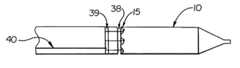
- FIG. 1is a side view of an embodiment of the invention wherein a catheter assembly having a slit sheath configuration is illustrated.
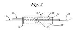
- FIG. 2is a partial top down view of the catheter assembly shown in FIG. 1 wherein an embodiment of the sheath is illustrated.
- FIG. 3is a partial top down view of the catheter assembly shown in FIG. 1 wherein an embodiment of the sheath is illustrated.
- FIG. 4is a partial top down view of the catheter assembly shown in FIG. 1 wherein an embodiment of the sheath is illustrated.
- FIG. 5is a partial top down view of the catheter assembly shown in FIG. 1 wherein an embodiment of the sheath is illustrated.
- FIG. 6is a side view of an embodiment of the invention wherein the catheter assembly is configured for delivery of a pant style bifurcated stent.
- FIG. 7is a side view of the embodiment of the invention wherein the catheter assembly comprises a proximal sheath and a distal sheath.
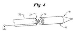
- FIG. 8is a perspective view of an embodiment of the invention wherein the proximal member and the distal member are separated.
- FIG. 9is a side view of the embodiment shown in FIG. 8 in the engaged state.
- FIG. 10is a side view of the embodiment shown in FIG. 8 in the unengaged state with a barrier member.
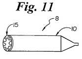
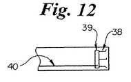
- FIGS. 11 and 12are side views of an embodiment of the invention wherein the sheath engagement mechanism and pull back mechanism are shown.
- FIG. 13is a side view of the embodiment of FIGS. 11 and 12 wherein the catheter assembly is shown in the engaged state.
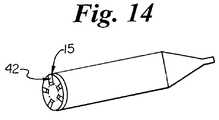
- FIG. 14is a perspective view of the distal member with clutch housing shown.
- FIG. 15is a side view of an embodiment shown in FIG. 14 unengaged to the proximal member.
- FIG. 16is a side view of an embodiment shown in FIG. 14 engaged to the proximal member.
- FIG. 17is a perspective view of the distal member with clutch housing and through hole shown.
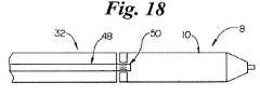
- FIG. 18is a side view of an embodiment shown in FIG. 17 unengaged to the proximal member.
- FIG. 19is a side view of an embodiment shown in FIG. 17 engaged to the proximal member.
- FIG. 20is a side view of an embodiment of the invention in the engaged state.
- FIG. 21is a side view of an embodiment of the invention in the engaged state.
- FIG. 22is a side view of an embodiment of the invention in the unengaged state.
- FIG. 23is a side view of an embodiment of the invention in the engaged state.
- FIG. 1a side view of an embodiment of a distal member 8 of the invention is shown.
- the sheath 10covers a stent 12 having a first guidewire 14 and a second guidewire 16 passing through it.
- a stent 12can be used in a vessel bifurcation.
- the distal member 8is advanced along two guide wires 14 and 16 .
- the first guidewire 14is positioned in the primary passage or branch vessel and the second guidewire 16 diverges from the first guidewire 14 upon passage into the secondary branch in the region of the bifurcation.
- the sheath 10may then rotate so as to be aligned with the side wall passage at the bifurcation.
- the sheath 10has a slit 18 which allows the sheath 10 to be retracted without first removing second guidewire 16 .
- the sheath 10is engaged to stent sheath clutch housing 15 .
- the different embodiments of the mechanism 15are shown in detail in later figures.
- the sheath 10is retracted before the stent 12 is deployed.
- FIG. 2a partial top down view of the catheter assembly 8 shown in FIG. 1 is illustrated.
- the stent 12has a special cell 20 that provides structure through which another medical device may pass.
- the special cell 20may extend at an oblique angle into the bifurcation.
- the slit 18has a substantially s-shaped configuration. Such a substantially s-shaped slit may prevent the stent 12 from trying to force itself into a non-round position beneath the sheath 10 .
- the substantially s-shaped slit 18may comprise a variety of different shapes, lengths, and configurations.
- the slit 18comprises two peaks 22 and valleys 24 .
- the magnitude of the peaks and valleysmay be substantially similar. However, in some embodiments a far greater number of peaks 22 and valleys 24 may be beneficial. Additionally, in some embodiments a far wider array of magnitudes for both the peaks and/or valleys may be beneficial.
- the slit 18may be held together with a holding member 26 .
- hook and loop material, snaps, buttons, screws, adhesives, and/or magnetic material, etcmay be used as the holding member 26 .
- the holding member 26is a thread which can lace the edges of the slit together and can be unraveled prior to the pulling of the sheath 10 or as the sheath 10 is being retracted.
- the slit 18 of the sheath 10may have spiraled configurations.
- One such embodimentis shown in FIG. 5 .
- the slit 18may be unnecessary.
- the stentmay be of the sort illustrated having a pant leg design.
- the stent 12has two longitudinal portions wherein the first longitudinal portion 12 a is disposed about first guidewire 14 along the length of first longitudinal portion 12 a and second longitudinal portion 12 b is disposed about second guidewire 16 along the length of second longitudinal portion 12 b .
- the stentmay have a self expanding pant design.
- the second longitudinal portion 12 b of the stent 12is disposed about second guidewire 16 while the first longitudinal portion 12 a of the stent 12 is disposed about first guidewire 14 passing through the tip of the stent end of the delivery system 28 .
- the sheath 10is split into a proximal sheath portion 10 a and a distal sheath portion 10 b as illustrated in FIG. 7 .
- the distal sheath portion 10 bmay be moved distally while the proximal sheath portion 10 a may be moved proximally, thus allowing the stent 12 to expand from the center of the stent 12 to the ends of the stent 12 rather than from one end of the stent 12 to another (e.g. from the distal end to the proximal end).
- FIG. 8an embodiment of the invention is shown wherein the sheath 10 is disposed over the distal member 8 of the catheter assembly.
- the stent sheath clutch housing 15is oval shaped and has a magnetically attracted surface.
- the clutch housing 15may be able to rotate about the catheter assembly.
- the distal end of the proximal member 32comprises a magnetic configuration 34 which may be able to rotate.
- the distal end of the proximal member 32engages stent sheath clutch housing 15 of the distal member 8 such that the stent sheath 10 may be retracted by retracting the proximal member 32 .
- Proximal member 32 and the distal member 8are shown engaged in FIG. 9 .
- the magnetic attraction between stent sheath clutch housing 15 and magnetic configuration 34substantially disappears when current is no longer flowing to the configuration 34 .
- the configuration 34may also be a permanent magnet.
- the proximal member 32 and stent sheath clutch housing 15may be advanced with a barrier member 36 between them. When the barrier member 36 is removed the attractive forces between the clutch housing 15 and the configuration 34 on proximal member 32 may be capable of retracting stent sheath 10 upon moving the proximal member 32 in a proximal direction.
- the distal member 8may have a clutch housing 15 of a looped wire (metallic or polymer) ring and/or a metallic or polymer locking ring which may consist of a band disposed inside or outside distal member 8 .
- a looped wire ringmay be included.
- the hooks 38 of FIG. 12may be attached to grappling base 39 which can be pushed forward by distal movement of push/pull wire 40 .
- the hooks 38may be extended distally beyond the distal most portion of proximal member 32 and engage the clutch housing 15 of distal member 8 . Once engaged as illustrated in FIG. 13 , proximal movement of the proximal member 32 or proximal movement of push/pull wire 40 may retract sheath 10 .
- the clutch housing 15may have hooks 42 which can be restrained from extending proximally with an intervening device or barrier member 36 as in FIG. 10 .
- the clutch housing 15 having hooks 42may be of a shape memory material that returns to an original extended shape upon heating. For example, when the hooks 42 are heated by the warmth of the body lumen or by electrical resistance they may extend proximally from clutch housing 15 .
- the clutch housing 15in at least one embodiment may have hooks 42 which are magnetically attracted to extend proximally towards the proximal member 32 . This may comprise an electrically induced magnetic attraction.
- a pullwiremay also be used to pull the hooks 42 proximally from the clutch housing 15 .
- the hooks 42are intended to engage the proximal member 32 through proximal member engagement mechanism 44 arranged about the opening of the proximal member 32 .
- the mechanism 44in some embodiments may be wire loop rings arranged about the distal opening of the proximal member 32 or a lock ring arranged about the distal opening of the proximal member 32 as shown in FIGS. 15 and 16 .
- a distal member 8has a through hole 46 .
- the distal member 8 of FIG. 17illustrates at least one embodiment.
- Proximal member 32may be positioned such that inner clutch extension 48 extends into through hole 46 .
- FIG. 18At least one embodiment is shown in FIG. 18 .
- Inner clutch extension 48may have expanding fingers 50 on its distal end. The distal member 8 may rotate around the expanding fingers 50 much like bearings. As shown in FIG. 19 , upon the inner clutch extension 48 being advanced distally, the fingers 50 may expand such that proximal retraction of the inner clutch extension 48 may retract the sheath 10 as well.
- the clutch extension 48may comprise an inflation lumen 52 for inflating balloon 54 .
- the balloon 54Before insertion into the through hole 46 the balloon 54 may be partially inflated or the balloon may be deflated in order for the clutch extension 48 to pass through through hole 46 .
- the balloon 54Upon insertion, the balloon 54 may be inflated thereby inhibiting the proximal motion of clutch extension 48 in relation to through hole 46 .
- proximal motion of the clutch extension 48may result in the sheath 10 being retracted.
- This inventionincludes the use of balloon expandable stents. Though the use of a sheath has application with balloon expandable stents, in at least one embodiment a sheath is not necessary. As illustrated in FIG. 22 the stent 12 may be disposed about balloon 58 without a sheath. The balloon 58 may be free to rotate about clutch extension 48 in order to better place and deploy the stent. Use at bifurcations is at least one application of this invention. The balloon 58 may be sealingly engaged to the clutch extension 48 at the distal and/or the proximal portions of the balloon 58 . In FIG. 22 proximal expandable seal 60 and distal expandable seal 62 are at least partially uninflated.
- the balloon 58 and clutch extension 48may be moved together proximally by inflating the proximal expandable seal 60 and/or the distal expandable seal 62 .
- the inflated stateis shown in FIG. 23 . It should be noted that the balloon 58 may rotate in this inflated state.
- the clutch extension 48does not have the proximal member 32 disposed about it at the distal portion of the proximal member 32 .
- the proximal member 32may be disposed about clutch extension 48 and may extend distally to the proximal end of balloon 58 and in some embodiments be disposed about balloon 58 and stent 12 .
- the clutch extension 48has diameters which are unequal at the proximal contacting balloon section 64 and the distal contacting balloon section 66 .
- clutch extension 48may be of the substantially same diameter at all locations on the member 48 and longitudinally aligned along all portions of the member 48 .
- the proximal contacting balloon section 64 and the distal contacting balloon section 66may have substantially similar diameters.
- different lumensmay be used in inflating the balloon 58 , the proximal expandable seal 60 , and/or the distal expandable seal 62 .
- the balloon 58 , the proximal expandable seal 60 , and the distal expandable seal 62may also share one or more inflation lumens.
- any dependent claim which followsshould be taken as alternatively written in a multiple dependent form from all prior claims which possess all antecedents referenced in such dependent claim if such multiple dependent format is an accepted format within the jurisdiction (e.g. each claim depending directly from claim 1 should be alternatively taken as depending from all previous claims).
- each claim depending directly from claim 1should be alternatively taken as depending from all previous claims.
- the following dependent claimsshould each be also taken as alternatively written in each singly dependent claim format which creates a dependency from a prior antecedent-possessing claim other than the specific claim listed in such dependent claim below.
Landscapes
- Health & Medical Sciences (AREA)
- Engineering & Computer Science (AREA)
- Biomedical Technology (AREA)
- Cardiology (AREA)
- Oral & Maxillofacial Surgery (AREA)
- Transplantation (AREA)
- Heart & Thoracic Surgery (AREA)
- Vascular Medicine (AREA)
- Life Sciences & Earth Sciences (AREA)
- Animal Behavior & Ethology (AREA)
- General Health & Medical Sciences (AREA)
- Public Health (AREA)
- Veterinary Medicine (AREA)
- Surgical Instruments (AREA)
- Media Introduction/Drainage Providing Device (AREA)
Abstract
Description
Claims (20)
Priority Applications (8)
| Application Number | Priority Date | Filing Date | Title |
|---|---|---|---|
| US10/641,488US8784472B2 (en) | 2003-08-15 | 2003-08-15 | Clutch driven stent delivery system |
| EP04751443AEP1653882B1 (en) | 2003-08-15 | 2004-05-05 | Clutch driven stent delivery system |
| PCT/US2004/014051WO2005018498A1 (en) | 2003-08-15 | 2004-05-05 | Clutch driven stent delivery system |
| AT04751443TATE397430T1 (en) | 2003-08-15 | 2004-05-05 | CLUTCH DRIVEN STENT DELIVERY SYSTEM |
| CA002529416ACA2529416A1 (en) | 2003-08-15 | 2004-05-05 | Clutch driven stent delivery system |
| ES04751443TES2310292T3 (en) | 2003-08-15 | 2004-05-05 | CLUTCH OPERATED ENDOPROTESIS PLACEMENT SYSTEM. |
| DE602004014279TDE602004014279D1 (en) | 2003-08-15 | 2004-05-05 | |
| JP2006523177AJP4704339B2 (en) | 2003-08-15 | 2004-05-05 | Clutch-driven stent delivery system |
Applications Claiming Priority (1)
| Application Number | Priority Date | Filing Date | Title |
|---|---|---|---|
| US10/641,488US8784472B2 (en) | 2003-08-15 | 2003-08-15 | Clutch driven stent delivery system |
Publications (2)
| Publication Number | Publication Date |
|---|---|
| US20050038494A1 US20050038494A1 (en) | 2005-02-17 |
| US8784472B2true US8784472B2 (en) | 2014-07-22 |
Family
ID=34136363
Family Applications (1)
| Application Number | Title | Priority Date | Filing Date |
|---|---|---|---|
| US10/641,488Expired - Fee RelatedUS8784472B2 (en) | 2003-08-15 | 2003-08-15 | Clutch driven stent delivery system |
Country Status (8)
| Country | Link |
|---|---|
| US (1) | US8784472B2 (en) |
| EP (1) | EP1653882B1 (en) |
| JP (1) | JP4704339B2 (en) |
| AT (1) | ATE397430T1 (en) |
| CA (1) | CA2529416A1 (en) |
| DE (1) | DE602004014279D1 (en) |
| ES (1) | ES2310292T3 (en) |
| WO (1) | WO2005018498A1 (en) |
Cited By (28)
| Publication number | Priority date | Publication date | Assignee | Title |
|---|---|---|---|---|
| US20120172887A1 (en)* | 2011-01-05 | 2012-07-05 | Wilson-Cook Medical, Inc. d/b/a Cook Endoscopy | Proximal Release Expandable Prosthesis Delivery System |
| US20140324164A1 (en)* | 2011-08-05 | 2014-10-30 | Mitraltech Ltd. | Techniques for percutaneous mitral valve replacement and sealing |
| US9387078B2 (en) | 2011-08-05 | 2016-07-12 | Mitraltech Ltd. | Percutaneous mitral valve replacement and sealing |
| US9498332B2 (en) | 2012-11-13 | 2016-11-22 | Mitraltech Ltd. | Percutaneously-deliverable mechanical valve |
| US9681952B2 (en) | 2013-01-24 | 2017-06-20 | Mitraltech Ltd. | Anchoring of prosthetic valve supports |
| US9763657B2 (en) | 2010-07-21 | 2017-09-19 | Mitraltech Ltd. | Techniques for percutaneous mitral valve replacement and sealing |
| US9788941B2 (en) | 2010-03-10 | 2017-10-17 | Mitraltech Ltd. | Axially-shortening prosthetic valve |
| USD800908S1 (en) | 2016-08-10 | 2017-10-24 | Mitraltech Ltd. | Prosthetic valve element |
| US9974651B2 (en) | 2015-02-05 | 2018-05-22 | Mitral Tech Ltd. | Prosthetic valve with axially-sliding frames |
| USD841812S1 (en) | 2017-08-03 | 2019-02-26 | Cardiovalve Ltd. | Prosthetic heart valve element |
| US10376361B2 (en) | 2011-08-05 | 2019-08-13 | Cardiovalve Ltd. | Techniques for percutaneous mitral valve replacement and sealing |
| US10390952B2 (en) | 2015-02-05 | 2019-08-27 | Cardiovalve Ltd. | Prosthetic valve with flexible tissue anchor portions |
| US10492908B2 (en) | 2014-07-30 | 2019-12-03 | Cardiovalve Ltd. | Anchoring of a prosthetic valve |
| US10531866B2 (en) | 2016-02-16 | 2020-01-14 | Cardiovalve Ltd. | Techniques for providing a replacement valve and transseptal communication |
| US10548726B2 (en) | 2009-12-08 | 2020-02-04 | Cardiovalve Ltd. | Rotation-based anchoring of an implant |
| US10575948B2 (en) | 2017-08-03 | 2020-03-03 | Cardiovalve Ltd. | Prosthetic heart valve |
| US10856975B2 (en) | 2016-08-10 | 2020-12-08 | Cardiovalve Ltd. | Prosthetic valve with concentric frames |
| US10888421B2 (en) | 2017-09-19 | 2021-01-12 | Cardiovalve Ltd. | Prosthetic heart valve with pouch |
| US11246704B2 (en) | 2017-08-03 | 2022-02-15 | Cardiovalve Ltd. | Prosthetic heart valve |
| US11291546B2 (en) | 2011-08-05 | 2022-04-05 | Cardiovalve Ltd. | Leaflet clip with collars |
| US11382746B2 (en) | 2017-12-13 | 2022-07-12 | Cardiovalve Ltd. | Prosthetic valve and delivery tool therefor |
| US11633277B2 (en) | 2018-01-10 | 2023-04-25 | Cardiovalve Ltd. | Temperature-control during crimping of an implant |
| US11653910B2 (en) | 2010-07-21 | 2023-05-23 | Cardiovalve Ltd. | Helical anchor implantation |
| US11793633B2 (en) | 2017-08-03 | 2023-10-24 | Cardiovalve Ltd. | Prosthetic heart valve |
| US20240032776A1 (en)* | 2006-09-01 | 2024-02-01 | Intuitive Surgical Operations, Inc. | Precision control systems for tissue visualization and manipulation assemblies |
| US12029646B2 (en) | 2017-08-03 | 2024-07-09 | Cardiovalve Ltd. | Prosthetic heart valve |
| US12053379B2 (en) | 2016-08-01 | 2024-08-06 | Cardiovalve Ltd. | Minimally-invasive delivery systems |
| US12357459B2 (en) | 2020-12-03 | 2025-07-15 | Cardiovalve Ltd. | Transluminal delivery system |
Families Citing this family (54)
| Publication number | Priority date | Publication date | Assignee | Title |
|---|---|---|---|---|
| US6951572B1 (en)* | 1997-02-20 | 2005-10-04 | Endologix, Inc. | Bifurcated vascular graft and method and apparatus for deploying same |
| US6261316B1 (en) | 1999-03-11 | 2001-07-17 | Endologix, Inc. | Single puncture bifurcation graft deployment system |
| US8034100B2 (en)* | 1999-03-11 | 2011-10-11 | Endologix, Inc. | Graft deployment system |
| WO2002039888A2 (en)* | 2000-11-15 | 2002-05-23 | Endologix, Inc. | Implantable vascular graft |
| GB0121980D0 (en)* | 2001-09-11 | 2001-10-31 | Cathnet Science Holding As | Expandable stent |
| US7137993B2 (en)* | 2001-12-03 | 2006-11-21 | Xtent, Inc. | Apparatus and methods for delivery of multiple distributed stents |
| US7147656B2 (en)* | 2001-12-03 | 2006-12-12 | Xtent, Inc. | Apparatus and methods for delivery of braided prostheses |
| US7309350B2 (en)* | 2001-12-03 | 2007-12-18 | Xtent, Inc. | Apparatus and methods for deployment of vascular prostheses |
| US20030135266A1 (en)* | 2001-12-03 | 2003-07-17 | Xtent, Inc. | Apparatus and methods for delivery of multiple distributed stents |
| US7351255B2 (en)* | 2001-12-03 | 2008-04-01 | Xtent, Inc. | Stent delivery apparatus and method |
| US20040186551A1 (en) | 2003-01-17 | 2004-09-23 | Xtent, Inc. | Multiple independent nested stent structures and methods for their preparation and deployment |
| US7182779B2 (en)* | 2001-12-03 | 2007-02-27 | Xtent, Inc. | Apparatus and methods for positioning prostheses for deployment from a catheter |
| US7892273B2 (en)* | 2001-12-03 | 2011-02-22 | Xtent, Inc. | Custom length stent apparatus |
| US7241308B2 (en)* | 2003-06-09 | 2007-07-10 | Xtent, Inc. | Stent deployment systems and methods |
| US20070156225A1 (en)* | 2003-12-23 | 2007-07-05 | Xtent, Inc. | Automated control mechanisms and methods for custom length stent apparatus |
| US7326236B2 (en)* | 2003-12-23 | 2008-02-05 | Xtent, Inc. | Devices and methods for controlling and indicating the length of an interventional element |
| US7323006B2 (en)* | 2004-03-30 | 2008-01-29 | Xtent, Inc. | Rapid exchange interventional devices and methods |
| US8317859B2 (en) | 2004-06-28 | 2012-11-27 | J.W. Medical Systems Ltd. | Devices and methods for controlling expandable prostheses during deployment |
| US20050288766A1 (en) | 2004-06-28 | 2005-12-29 | Xtent, Inc. | Devices and methods for controlling expandable prostheses during deployment |
| WO2006066150A2 (en)* | 2004-12-16 | 2006-06-22 | Carlos Ruiz | Separable sheath and method of using |
| US7402168B2 (en)* | 2005-04-11 | 2008-07-22 | Xtent, Inc. | Custom-length stent delivery system with independently operable expansion elements |
| EP1906888A1 (en)* | 2005-05-24 | 2008-04-09 | Abbott Laboratories | Bifurcation stent delivery catheter assembly and method |
| WO2007109621A2 (en) | 2006-03-20 | 2007-09-27 | Xtent, Inc. | Apparatus and methods for deployment of linked prosthetic segments |
| US20070281117A1 (en)* | 2006-06-02 | 2007-12-06 | Xtent, Inc. | Use of plasma in formation of biodegradable stent coating |
| WO2008021570A2 (en)* | 2006-08-18 | 2008-02-21 | Abbott Laboratories | Bifurcation stent delivery catheter and method |
| US9044350B2 (en)* | 2006-08-21 | 2015-06-02 | Boston Scientific Scimed, Inc. | Alignment sheath apparatus and method |
| WO2008024943A1 (en)* | 2006-08-23 | 2008-02-28 | Abbott Laboratories | Catheter system and method for delivering medical devices |
| US20080071343A1 (en)* | 2006-09-15 | 2008-03-20 | Kevin John Mayberry | Multi-segmented graft deployment system |
| US8523931B2 (en)* | 2007-01-12 | 2013-09-03 | Endologix, Inc. | Dual concentric guidewire and methods of bifurcated graft deployment |
| US20080199510A1 (en) | 2007-02-20 | 2008-08-21 | Xtent, Inc. | Thermo-mechanically controlled implants and methods of use |
| US8486132B2 (en) | 2007-03-22 | 2013-07-16 | J.W. Medical Systems Ltd. | Devices and methods for controlling expandable prostheses during deployment |
| US8273115B2 (en)* | 2007-04-24 | 2012-09-25 | W. L. Gore & Associates, Inc. | Side branched endoluminal prostheses and methods of delivery thereof |
| US9358142B2 (en)* | 2007-04-24 | 2016-06-07 | W. L. Gore & Associates, Inc. | Catheter having guidewire channel |
| WO2009105699A1 (en) | 2008-02-22 | 2009-08-27 | Endologix, Inc. | Design and method of placement of a graft or graft system |
| US9101503B2 (en)* | 2008-03-06 | 2015-08-11 | J.W. Medical Systems Ltd. | Apparatus having variable strut length and methods of use |
| US8236040B2 (en)* | 2008-04-11 | 2012-08-07 | Endologix, Inc. | Bifurcated graft deployment systems and methods |
| EP2520320B1 (en) | 2008-07-01 | 2016-11-02 | Endologix, Inc. | Catheter system |
| DE102008048416A1 (en)* | 2008-08-05 | 2010-02-11 | Acandis Gmbh & Co. Kg | Medical device and method for manufacturing such a device |
| US8133199B2 (en) | 2008-08-27 | 2012-03-13 | Boston Scientific Scimed, Inc. | Electroactive polymer activation system for a medical device |
| US9149376B2 (en)* | 2008-10-06 | 2015-10-06 | Cordis Corporation | Reconstrainable stent delivery system |
| US20110054587A1 (en)* | 2009-04-28 | 2011-03-03 | Endologix, Inc. | Apparatus and method of placement of a graft or graft system |
| US10772717B2 (en) | 2009-05-01 | 2020-09-15 | Endologix, Inc. | Percutaneous method and device to treat dissections |
| JP2012525239A (en)* | 2009-05-01 | 2012-10-22 | エンドロジックス、インク | Transcutaneous methods and devices for treating dissociation (priority information and incorporation by reference) |
| WO2011008989A2 (en) | 2009-07-15 | 2011-01-20 | Endologix, Inc. | Stent graft |
| WO2011017123A2 (en) | 2009-07-27 | 2011-02-10 | Endologix, Inc. | Stent graft |
| US20110218617A1 (en)* | 2010-03-02 | 2011-09-08 | Endologix, Inc. | Endoluminal vascular prosthesis |
| KR101160650B1 (en)* | 2010-05-14 | 2012-06-29 | (주) 태웅메디칼 | Plastic stent |
| US20120109279A1 (en) | 2010-11-02 | 2012-05-03 | Endologix, Inc. | Apparatus and method of placement of a graft or graft system |
| US9393100B2 (en) | 2010-11-17 | 2016-07-19 | Endologix, Inc. | Devices and methods to treat vascular dissections |
| US8808350B2 (en) | 2011-03-01 | 2014-08-19 | Endologix, Inc. | Catheter system and methods of using same |
| US8574283B1 (en)* | 2011-08-30 | 2013-11-05 | Suraj Govind Kamat | Deployment of stents within bifurcated vessels |
| WO2017004265A1 (en) | 2015-06-30 | 2017-01-05 | Endologix, Inc. | Locking assembly for coupling guidewire to delivery system |
| JP6854282B2 (en)* | 2015-09-18 | 2021-04-07 | テルモ株式会社 | Pressable implant delivery system |
| WO2023220215A1 (en)* | 2022-05-12 | 2023-11-16 | Edwards Lifesciences Corporation | Expandable medical access sheaths |
Citations (116)
| Publication number | Priority date | Publication date | Assignee | Title |
|---|---|---|---|---|
| US4448195A (en) | 1981-05-08 | 1984-05-15 | Leveen Harry H | Reinforced balloon catheter |
| US4484585A (en) | 1981-09-12 | 1984-11-27 | Richard Wolf Gmbh | Catheters |
| US4601701A (en) | 1985-02-25 | 1986-07-22 | Argon Medical Corp. | Multi-purpose multi-lumen catheter |
| US4769005A (en) | 1987-08-06 | 1988-09-06 | Robert Ginsburg | Selective catheter guide |
| US4776337A (en) | 1985-11-07 | 1988-10-11 | Expandable Grafts Partnership | Expandable intraluminal graft, and method and apparatus for implanting an expandable intraluminal graft |
| US4913141A (en) | 1988-10-25 | 1990-04-03 | Cordis Corporation | Apparatus and method for placement of a stent within a subject vessel |
| US4994071A (en) | 1989-05-22 | 1991-02-19 | Cordis Corporation | Bifurcating stent apparatus and method |
| US4998923A (en) | 1988-08-11 | 1991-03-12 | Advanced Cardiovascular Systems, Inc. | Steerable dilatation catheter |
| US5019085A (en) | 1988-10-25 | 1991-05-28 | Cordis Corporation | Apparatus and method for placement of a stent within a subject vessel |
| US5122154A (en) | 1990-08-15 | 1992-06-16 | Rhodes Valentine J | Endovascular bypass graft |
| US5147387A (en)* | 1990-10-10 | 1992-09-15 | W. L. Gore & Associates, Inc. | Process of implanting a prosthetic sheet repair material |
| FR2678508A1 (en) | 1991-07-04 | 1993-01-08 | Celsa Lg | Device for reinforcing the vessels of the human body |
| US5195984A (en) | 1988-10-04 | 1993-03-23 | Expandable Grafts Partnership | Expandable intraluminal graft |
| US5219355A (en) | 1990-10-03 | 1993-06-15 | Parodi Juan C | Balloon device for implanting an aortic intraluminal prosthesis for repairing aneurysms |
| US5316023A (en) | 1992-01-08 | 1994-05-31 | Expandable Grafts Partnership | Method for bilateral intra-aortic bypass |
| US5397305A (en) | 1990-12-21 | 1995-03-14 | Advanced Cardiovascular Systems, Inc. | Fixed-wire dilatation catheter with rotatable balloon assembly |
| US5449353A (en) | 1990-10-31 | 1995-09-12 | Kao Corporation | Disposable diaper |
| US5477856A (en) | 1991-02-15 | 1995-12-26 | Lundquist; Ingemar H. | Torquable catheter and torquable tubular member for use therewith |
| DE29701758U1 (en) | 1997-02-01 | 1997-03-27 | Jomed Implantate GmbH, 72414 Rangendingen | Radially expandable stent for implantation in a body vessel, particularly in the area of a vascular branch |
| US5632763A (en) | 1995-01-19 | 1997-05-27 | Cordis Corporation | Bifurcated stent and method for implanting same |
| US5643278A (en) | 1995-04-06 | 1997-07-01 | Leocor, Inc. | Stent delivery system |
| US5683451A (en)* | 1994-06-08 | 1997-11-04 | Cardiovascular Concepts, Inc. | Apparatus and methods for deployment release of intraluminal prostheses |
| US5683345A (en) | 1994-10-27 | 1997-11-04 | Novoste Corporation | Method and apparatus for treating a desired area in the vascular system of a patient |
| US5697971A (en) | 1996-06-11 | 1997-12-16 | Fischell; Robert E. | Multi-cell stent with cells having differing characteristics |
| US5725519A (en) | 1996-09-30 | 1998-03-10 | Medtronic Instent Israel Ltd. | Stent loading device for a balloon catheter |
| US5749825A (en) | 1996-09-18 | 1998-05-12 | Isostent, Inc. | Means method for treatment of stenosed arterial bifurcations |
| US5755734A (en) | 1996-05-03 | 1998-05-26 | Medinol Ltd. | Bifurcated stent and method of making same |
| US5755778A (en) | 1996-10-16 | 1998-05-26 | Nitinol Medical Technologies, Inc. | Anastomosis device |
| US5772669A (en) | 1996-09-27 | 1998-06-30 | Scimed Life Systems, Inc. | Stent deployment catheter with retractable sheath |
| US5797952A (en)* | 1996-06-21 | 1998-08-25 | Localmed, Inc. | System and method for delivering helical stents |
| US5873906A (en) | 1994-09-08 | 1999-02-23 | Gore Enterprise Holdings, Inc. | Procedures for introducing stents and stent-grafts |
| US5876374A (en) | 1992-11-02 | 1999-03-02 | Localmed, Inc. | Catheter sleeve for use with a balloon catheter |
| US5893868A (en) | 1997-03-05 | 1999-04-13 | Scimed Life Systems, Inc. | Catheter with removable balloon protector and stent delivery system with removable stent protector |
| US5906640A (en) | 1994-11-03 | 1999-05-25 | Divysio Solutions Ulc | Bifurcated stent and method for the manufacture and delivery of same |
| US5908405A (en) | 1994-10-28 | 1999-06-01 | Intella Interventional Systems, Inc. | Low profile balloon-on-a-wire catheter with shapeable and/or deflectable tip and method |
| US5935161A (en) | 1993-11-04 | 1999-08-10 | C. R. Bard, Inc. | Non-migrating vascular prosthesis and minimally invasive placement system therefor |
| US5941908A (en) | 1997-04-23 | 1999-08-24 | Vascular Science, Inc. | Artificial medical graft with a releasable retainer |
| US5951569A (en) | 1997-04-29 | 1999-09-14 | Medtronic, Inc. | Stent delivery system |
| US5957929A (en) | 1997-05-02 | 1999-09-28 | Micro Therapeutics, Inc. | Expandable stent apparatus and method |
| US5961548A (en) | 1997-11-18 | 1999-10-05 | Shmulewitz; Ascher | Bifurcated two-part graft and methods of implantation |
| US5961546A (en) | 1993-04-22 | 1999-10-05 | C.R. Bard, Inc. | Method and apparatus for recapture of hooked endoprosthesis |
| US6013092A (en) | 1998-08-18 | 2000-01-11 | Baxter International Inc. | Folding of catheter-mounted balloons to facilitate non-rotational radial expansion of intraluminal devices |
| US6017362A (en) | 1994-04-01 | 2000-01-25 | Gore Enterprise Holdings, Inc. | Folding self-expandable intravascular stent |
| US6027460A (en) | 1995-09-14 | 2000-02-22 | Shturman Cardiology Systems, Inc. | Rotatable intravascular apparatus |
| US6033434A (en) | 1995-06-08 | 2000-03-07 | Ave Galway Limited | Bifurcated endovascular stent and methods for forming and placing |
| US6048361A (en) | 1997-05-17 | 2000-04-11 | Jomed Implantate Gmbh | Balloon catheter and multi-guidewire stent for implanting in the region of branched vessels |
| US6056775A (en) | 1996-05-31 | 2000-05-02 | Ave Galway Limited | Bifurcated endovascular stents and method and apparatus for their placement |
| US6056722A (en) | 1997-09-18 | 2000-05-02 | Iowa-India Investments Company Limited Of Douglas | Delivery mechanism for balloons, drugs, stents and other physical/mechanical agents and methods of use |
| US6059813A (en)* | 1998-11-06 | 2000-05-09 | Scimed Life Systems, Inc. | Rolling membrane stent delivery system |
| US6071286A (en) | 1997-02-19 | 2000-06-06 | Mawad; Michel E. | Combination angioplasty balloon/stent deployment device |
| US6090127A (en) | 1995-10-16 | 2000-07-18 | Medtronic, Inc. | Medical stents, apparatus and method for making same |
| US6096073A (en) | 1997-02-25 | 2000-08-01 | Scimed Life Systems, Inc. | Method of deploying a stent at a lesion site located at a bifurcation in a parent vessel |
| US6110191A (en) | 1996-09-12 | 2000-08-29 | Edwards Lifesciences, Llc | Endovascular delivery system |
| US6120522A (en) | 1998-08-27 | 2000-09-19 | Scimed Life Systems, Inc. | Self-expanding stent delivery catheter |
| US6126685A (en)* | 1994-06-08 | 2000-10-03 | Medtronic, Inc. | Apparatus and methods for placement and repositioning of intraluminal prostheses |
| US6146415A (en) | 1999-05-07 | 2000-11-14 | Advanced Cardiovascular Systems, Inc. | Stent delivery system |
| US6152944A (en) | 1997-03-05 | 2000-11-28 | Scimed Life Systems, Inc. | Catheter with removable balloon protector and stent delivery system with removable stent protector |
| US6165195A (en) | 1997-08-13 | 2000-12-26 | Advanced Cardiovascylar Systems, Inc. | Stent and catheter assembly and method for treating bifurcations |
| US6165210A (en) | 1994-04-01 | 2000-12-26 | Gore Enterprise Holdings, Inc. | Self-expandable helical intravascular stent and stent-graft |
| US6190393B1 (en) | 1999-03-29 | 2001-02-20 | Cordis Corporation | Direct stent delivery catheter system |
| US6190360B1 (en) | 1999-04-09 | 2001-02-20 | Endotex Interventional System | Stent delivery handle |
| US6210431B1 (en) | 1999-12-10 | 2001-04-03 | John A. Power | Ostial bifurcation lesion stenting catheter |
| US6210380B1 (en) | 1998-08-24 | 2001-04-03 | Advanced Cardiovascular Systems, Inc. | Bifurcated catheter assembly |
| US6221090B1 (en) | 1997-08-13 | 2001-04-24 | Advanced Cardiovascular Systems, Inc. | Stent delivery assembly |
| US6221097B1 (en) | 1999-03-22 | 2001-04-24 | Scimed Life System, Inc. | Lubricated sleeve material for stent delivery |
| US6224587B1 (en) | 1999-11-22 | 2001-05-01 | C.R. Bard, Inc. | Steerable catheter |
| US6246914B1 (en) | 1999-08-12 | 2001-06-12 | Irvine Biomedical, Inc. | High torque catheter and methods thereof |
| US6254593B1 (en) | 1999-12-10 | 2001-07-03 | Advanced Cardiovascular Systems, Inc. | Bifurcated stent delivery system having retractable sheath |
| US6258052B1 (en) | 1997-11-13 | 2001-07-10 | Lumend, Inc. | Guidewire and catheter with rotating and reciprocating symmetrical or asymmetrical distal tip |
| US6264688B1 (en) | 1998-07-03 | 2001-07-24 | W. C. Heraeus Gmbh & Co. Kg | Radially expandable stent V |
| US6287277B1 (en) | 1997-04-28 | 2001-09-11 | Advanced Cardiovascular Systems, Inc. | Balloon formation by vacuum deposition |
| US6287330B1 (en) | 1996-09-03 | 2001-09-11 | Endovascular Technologies, Inc. | Aortoiliac grafting system and method |
| US6290673B1 (en) | 1999-05-20 | 2001-09-18 | Conor Medsystems, Inc. | Expandable medical device delivery system and method |
| US6299636B1 (en) | 1992-09-14 | 2001-10-09 | Meadox Medicals, Inc. | Radially self-expanding implantable intraluminal device |
| US6319275B1 (en) | 1999-04-07 | 2001-11-20 | Medtronic Ave, Inc. | Endolumenal prosthesis delivery assembly and method of use |
| US6322548B1 (en) | 1995-05-10 | 2001-11-27 | Eclipse Surgical Technologies | Delivery catheter system for heart chamber |
| US20010049548A1 (en) | 1999-06-04 | 2001-12-06 | Gil Vardi | Bifurcation lesion stent delivery using multiple guidewires |
| US20020019665A1 (en) | 1998-09-30 | 2002-02-14 | Mark Dehdashtian | Methods and apparatus for intraluminal placement of a bifurcated intraluminal graft |
| US20020019664A1 (en) | 1997-02-20 | 2002-02-14 | Douglas Myles S. | Bifurcated vascular graft and method and apparatus for deploying same |
| US6361544B1 (en) | 1997-08-13 | 2002-03-26 | Advanced Cardiovascular Systems, Inc. | Stent and catheter assembly and method for treating bifurcations |
| US6361555B1 (en) | 1999-12-15 | 2002-03-26 | Advanced Cardiovascular Systems, Inc. | Stent and stent delivery assembly and method of use |
| US20020038140A1 (en) | 2000-09-22 | 2002-03-28 | Dachuan Yang | Hybrid elastomer sleeve for stent delivery |
| US20020038141A1 (en) | 2000-09-22 | 2002-03-28 | Dachuan Yang | Sandwich striped sleeve for stent delively |
| US6364893B1 (en) | 1990-12-28 | 2002-04-02 | Scimed Life Systems, Inc. | Stent lining |
| US6375660B1 (en) | 1999-11-22 | 2002-04-23 | Cordis Corporation | Stent delivery system with a fixed guide wire |
| US6387120B2 (en) | 1999-12-09 | 2002-05-14 | Advanced Cardiovascular Systems, Inc. | Stent and catheter assembly and method for treating bifurcations |
| US6391050B1 (en) | 2000-02-29 | 2002-05-21 | Scimed Life Systems, Inc. | Self-expanding stent delivery system |
| US20020072755A1 (en)* | 2000-12-08 | 2002-06-13 | Bigus Stephen J. | Catheter with rotatable balloon |
| US6436104B2 (en) | 1996-01-26 | 2002-08-20 | Cordis Corporation | Bifurcated axially flexible stent |
| US20020116045A1 (en) | 2001-02-22 | 2002-08-22 | Eidenschink Tracee E.J. | Crimpable balloon/stent protector |
| US20020120320A1 (en) | 2001-01-04 | 2002-08-29 | Lixiao Wang | Combined shaped balloon and stent protector |
| US6443980B1 (en) | 1999-03-22 | 2002-09-03 | Scimed Life Systems, Inc. | End sleeve coating for stent delivery |
| US6475166B1 (en) | 2000-08-18 | 2002-11-05 | Endovascular Technologies, Inc. | Guidewire placement system for delivery of an aneurysm graft limb |
| US6482211B1 (en) | 2000-07-31 | 2002-11-19 | Advanced Cardiovascular Systems, Inc. | Angulated stent delivery system and method of use |
| US6482227B1 (en)* | 1998-03-30 | 2002-11-19 | Cordis Corporation | Stent graft having improved attachment within a body vessel |
| US6488694B1 (en) | 1991-01-28 | 2002-12-03 | Advanced Cardiovascular Systems, Inc. | Stent delivery system |
| US6508835B1 (en) | 1998-12-11 | 2003-01-21 | Endologix, Inc. | Endoluminal vascular prosthesis |
| US6514281B1 (en) | 1998-09-04 | 2003-02-04 | Scimed Life Systems, Inc. | System for delivering bifurcation stents |
| US6520988B1 (en) | 1997-09-24 | 2003-02-18 | Medtronic Ave, Inc. | Endolumenal prosthesis and method of use in bifurcation regions of body lumens |
| US6520983B1 (en) | 1998-03-31 | 2003-02-18 | Scimed Life Systems, Inc. | Stent delivery system |
| WO2003017872A1 (en) | 2001-08-23 | 2003-03-06 | Scimed Life Systems Inc | Rotating stent delivery system for side branch access and protection and method of using same. |
| US6530947B1 (en) | 1993-10-22 | 2003-03-11 | Scimed Life Systems, Inc | Stent delivery apparatus and method |
| US6533805B1 (en) | 1996-04-01 | 2003-03-18 | General Surgical Innovations, Inc. | Prosthesis and method for deployment within a body lumen |
| US20030055484A1 (en) | 1994-08-31 | 2003-03-20 | Lilip Lau | Exterior supported self-expanding stent-graft |
| US6572643B1 (en) | 2000-07-19 | 2003-06-03 | Vascular Architects, Inc. | Endoprosthesis delivery catheter assembly and method |
| US6589262B1 (en) | 2000-03-31 | 2003-07-08 | Medamicus, Inc. | Locking catheter introducing system |
| US6602226B1 (en) | 2000-10-12 | 2003-08-05 | Scimed Life Systems, Inc. | Low-profile stent delivery system and apparatus |
| US6607506B2 (en) | 2000-02-01 | 2003-08-19 | Harold D. Kletschka | Embolic protection device having an expandable trap |
| US6613067B1 (en) | 2000-06-06 | 2003-09-02 | Scimed Life Systems, Inc. | Balloon protector |
| US6629981B2 (en) | 2000-07-06 | 2003-10-07 | Endocare, Inc. | Stent delivery system |
| US20030191516A1 (en) | 2002-04-04 | 2003-10-09 | James Weldon | Delivery system and method for deployment of foreshortening endoluminal devices |
| US20030195546A1 (en) | 1998-05-15 | 2003-10-16 | Solar Ronald J. | Enhanced catheter with alignment means |
| US20030199966A1 (en)* | 2002-04-23 | 2003-10-23 | Brian Shiu | Integrated mechanical handle with quick slide mechanism |
| US20040087977A1 (en)* | 2000-03-06 | 2004-05-06 | United States Surgical | Apparatus and method for performing a bypass procedure in a digestive system |
| US6827731B2 (en)* | 2001-01-22 | 2004-12-07 | Gore Enterprise Holdings, Inc. | Deployment system for intraluminal devices |
| US6908477B2 (en)* | 2000-10-13 | 2005-06-21 | Rex Medical, L.P. | Methods of implanting covered stents with side branch |
Family Cites Families (4)
| Publication number | Priority date | Publication date | Assignee | Title |
|---|---|---|---|---|
| US1128A (en)* | 1839-04-19 | Improvement in inverting side-hill and horizontal plows | ||
| US191516A (en)* | 1877-06-05 | Improvement in telescopic or hydraulic elevators | ||
| DE69633263T2 (en)* | 1995-05-25 | 2005-09-08 | Medtronic, Inc., Minneapolis | STENT ARRANGEMENT |
| AUPO700897A0 (en)* | 1997-05-26 | 1997-06-19 | William A Cook Australia Pty Ltd | A method and means of deploying a graft |
- 2003
- 2003-08-15USUS10/641,488patent/US8784472B2/ennot_activeExpired - Fee Related
- 2004
- 2004-05-05JPJP2006523177Apatent/JP4704339B2/ennot_activeExpired - Fee Related
- 2004-05-05ESES04751443Tpatent/ES2310292T3/ennot_activeExpired - Lifetime
- 2004-05-05WOPCT/US2004/014051patent/WO2005018498A1/enactiveApplication Filing
- 2004-05-05DEDE602004014279Tpatent/DE602004014279D1/denot_activeExpired - Lifetime
- 2004-05-05EPEP04751443Apatent/EP1653882B1/ennot_activeExpired - Lifetime
- 2004-05-05CACA002529416Apatent/CA2529416A1/ennot_activeAbandoned
- 2004-05-05ATAT04751443Tpatent/ATE397430T1/ennot_activeIP Right Cessation
Patent Citations (139)
| Publication number | Priority date | Publication date | Assignee | Title |
|---|---|---|---|---|
| US4448195A (en) | 1981-05-08 | 1984-05-15 | Leveen Harry H | Reinforced balloon catheter |
| US4484585A (en) | 1981-09-12 | 1984-11-27 | Richard Wolf Gmbh | Catheters |
| US4601701A (en) | 1985-02-25 | 1986-07-22 | Argon Medical Corp. | Multi-purpose multi-lumen catheter |
| US4776337A (en) | 1985-11-07 | 1988-10-11 | Expandable Grafts Partnership | Expandable intraluminal graft, and method and apparatus for implanting an expandable intraluminal graft |
| US4776337B1 (en) | 1985-11-07 | 2000-12-05 | Cordis Corp | Expandable intraluminal graft and method and apparatus for implanting an expandable intraluminal graft |
| US4769005A (en) | 1987-08-06 | 1988-09-06 | Robert Ginsburg | Selective catheter guide |
| US4998923A (en) | 1988-08-11 | 1991-03-12 | Advanced Cardiovascular Systems, Inc. | Steerable dilatation catheter |
| US5195984A (en) | 1988-10-04 | 1993-03-23 | Expandable Grafts Partnership | Expandable intraluminal graft |
| US5019085A (en) | 1988-10-25 | 1991-05-28 | Cordis Corporation | Apparatus and method for placement of a stent within a subject vessel |
| US4913141A (en) | 1988-10-25 | 1990-04-03 | Cordis Corporation | Apparatus and method for placement of a stent within a subject vessel |
| US4994071A (en) | 1989-05-22 | 1991-02-19 | Cordis Corporation | Bifurcating stent apparatus and method |
| US5122154A (en) | 1990-08-15 | 1992-06-16 | Rhodes Valentine J | Endovascular bypass graft |
| US5219355A (en) | 1990-10-03 | 1993-06-15 | Parodi Juan C | Balloon device for implanting an aortic intraluminal prosthesis for repairing aneurysms |
| US5147387A (en)* | 1990-10-10 | 1992-09-15 | W. L. Gore & Associates, Inc. | Process of implanting a prosthetic sheet repair material |
| US5449353A (en) | 1990-10-31 | 1995-09-12 | Kao Corporation | Disposable diaper |
| US5397305A (en) | 1990-12-21 | 1995-03-14 | Advanced Cardiovascular Systems, Inc. | Fixed-wire dilatation catheter with rotatable balloon assembly |
| US6364893B1 (en) | 1990-12-28 | 2002-04-02 | Scimed Life Systems, Inc. | Stent lining |
| US6488694B1 (en) | 1991-01-28 | 2002-12-03 | Advanced Cardiovascular Systems, Inc. | Stent delivery system |
| US6582459B1 (en) | 1991-01-28 | 2003-06-24 | Advanced Cardiovascular Systems, Inc. | Stent delivery system |
| US6527789B1 (en)* | 1991-01-28 | 2003-03-04 | Advanced Cardiovascular Systems, Inc. | Stent delivery system |
| US5477856A (en) | 1991-02-15 | 1995-12-26 | Lundquist; Ingemar H. | Torquable catheter and torquable tubular member for use therewith |
| FR2678508A1 (en) | 1991-07-04 | 1993-01-08 | Celsa Lg | Device for reinforcing the vessels of the human body |
| US5316023A (en) | 1992-01-08 | 1994-05-31 | Expandable Grafts Partnership | Method for bilateral intra-aortic bypass |
| US6299636B1 (en) | 1992-09-14 | 2001-10-09 | Meadox Medicals, Inc. | Radially self-expanding implantable intraluminal device |
| US5876374A (en) | 1992-11-02 | 1999-03-02 | Localmed, Inc. | Catheter sleeve for use with a balloon catheter |
| US5961546A (en) | 1993-04-22 | 1999-10-05 | C.R. Bard, Inc. | Method and apparatus for recapture of hooked endoprosthesis |
| US6530947B1 (en) | 1993-10-22 | 2003-03-11 | Scimed Life Systems, Inc | Stent delivery apparatus and method |
| US6077297A (en) | 1993-11-04 | 2000-06-20 | C. R. Bard, Inc. | Non-migrating vascular prosthesis and minimally invasive placement system therefor |
| US5935161A (en) | 1993-11-04 | 1999-08-10 | C. R. Bard, Inc. | Non-migrating vascular prosthesis and minimally invasive placement system therefor |
| US6165210A (en) | 1994-04-01 | 2000-12-26 | Gore Enterprise Holdings, Inc. | Self-expandable helical intravascular stent and stent-graft |
| US6017362A (en) | 1994-04-01 | 2000-01-25 | Gore Enterprise Holdings, Inc. | Folding self-expandable intravascular stent |
| US6126685A (en)* | 1994-06-08 | 2000-10-03 | Medtronic, Inc. | Apparatus and methods for placement and repositioning of intraluminal prostheses |
| US5683451A (en)* | 1994-06-08 | 1997-11-04 | Cardiovascular Concepts, Inc. | Apparatus and methods for deployment release of intraluminal prostheses |
| US20030055484A1 (en) | 1994-08-31 | 2003-03-20 | Lilip Lau | Exterior supported self-expanding stent-graft |
| US5873906A (en) | 1994-09-08 | 1999-02-23 | Gore Enterprise Holdings, Inc. | Procedures for introducing stents and stent-grafts |
| US5683345A (en) | 1994-10-27 | 1997-11-04 | Novoste Corporation | Method and apparatus for treating a desired area in the vascular system of a patient |
| US5908405A (en) | 1994-10-28 | 1999-06-01 | Intella Interventional Systems, Inc. | Low profile balloon-on-a-wire catheter with shapeable and/or deflectable tip and method |
| US5906640A (en) | 1994-11-03 | 1999-05-25 | Divysio Solutions Ulc | Bifurcated stent and method for the manufacture and delivery of same |
| US5632763A (en) | 1995-01-19 | 1997-05-27 | Cordis Corporation | Bifurcated stent and method for implanting same |
| US5643278A (en) | 1995-04-06 | 1997-07-01 | Leocor, Inc. | Stent delivery system |
| US6322548B1 (en) | 1995-05-10 | 2001-11-27 | Eclipse Surgical Technologies | Delivery catheter system for heart chamber |
| US6033434A (en) | 1995-06-08 | 2000-03-07 | Ave Galway Limited | Bifurcated endovascular stent and methods for forming and placing |
| US6027460A (en) | 1995-09-14 | 2000-02-22 | Shturman Cardiology Systems, Inc. | Rotatable intravascular apparatus |
| US6090127A (en) | 1995-10-16 | 2000-07-18 | Medtronic, Inc. | Medical stents, apparatus and method for making same |
| US6436104B2 (en) | 1996-01-26 | 2002-08-20 | Cordis Corporation | Bifurcated axially flexible stent |
| US6533805B1 (en) | 1996-04-01 | 2003-03-18 | General Surgical Innovations, Inc. | Prosthesis and method for deployment within a body lumen |
| US5755735A (en) | 1996-05-03 | 1998-05-26 | Medinol Ltd. | Bifurcated stent and method of making same |
| US6406489B1 (en) | 1996-05-03 | 2002-06-18 | Medinol, Ltd. | Bifurcated stent and method of making same |
| US5755734A (en) | 1996-05-03 | 1998-05-26 | Medinol Ltd. | Bifurcated stent and method of making same |
| US6117156A (en) | 1996-05-03 | 2000-09-12 | Medinol Ltd. | Bifurcated stent and method of making same |
| US6056775A (en) | 1996-05-31 | 2000-05-02 | Ave Galway Limited | Bifurcated endovascular stents and method and apparatus for their placement |
| US5697971A (en) | 1996-06-11 | 1997-12-16 | Fischell; Robert E. | Multi-cell stent with cells having differing characteristics |
| US5797952A (en)* | 1996-06-21 | 1998-08-25 | Localmed, Inc. | System and method for delivering helical stents |
| US6287330B1 (en) | 1996-09-03 | 2001-09-11 | Endovascular Technologies, Inc. | Aortoiliac grafting system and method |
| US6379372B1 (en) | 1996-09-12 | 2002-04-30 | Edwards Lifesciences Corp. | Endovascular delivery system |
| US6143014A (en) | 1996-09-12 | 2000-11-07 | Baxter International, Inc. | Endovascular delivery system |
| US6110191A (en) | 1996-09-12 | 2000-08-29 | Edwards Lifesciences, Llc | Endovascular delivery system |
| US5749825A (en) | 1996-09-18 | 1998-05-12 | Isostent, Inc. | Means method for treatment of stenosed arterial bifurcations |
| US5772669A (en) | 1996-09-27 | 1998-06-30 | Scimed Life Systems, Inc. | Stent deployment catheter with retractable sheath |
| US5725519A (en) | 1996-09-30 | 1998-03-10 | Medtronic Instent Israel Ltd. | Stent loading device for a balloon catheter |
| US5921995A (en) | 1996-10-16 | 1999-07-13 | Nitinol Medical Technologies, Inc. | Anastomosis Device |
| US5755778A (en) | 1996-10-16 | 1998-05-26 | Nitinol Medical Technologies, Inc. | Anastomosis device |
| DE29701758U1 (en) | 1997-02-01 | 1997-03-27 | Jomed Implantate GmbH, 72414 Rangendingen | Radially expandable stent for implantation in a body vessel, particularly in the area of a vascular branch |
| US6071286A (en) | 1997-02-19 | 2000-06-06 | Mawad; Michel E. | Combination angioplasty balloon/stent deployment device |
| US20020019664A1 (en) | 1997-02-20 | 2002-02-14 | Douglas Myles S. | Bifurcated vascular graft and method and apparatus for deploying same |
| US6096073A (en) | 1997-02-25 | 2000-08-01 | Scimed Life Systems, Inc. | Method of deploying a stent at a lesion site located at a bifurcation in a parent vessel |
| US6152944A (en) | 1997-03-05 | 2000-11-28 | Scimed Life Systems, Inc. | Catheter with removable balloon protector and stent delivery system with removable stent protector |
| US5893868A (en) | 1997-03-05 | 1999-04-13 | Scimed Life Systems, Inc. | Catheter with removable balloon protector and stent delivery system with removable stent protector |
| US20010001128A1 (en) | 1997-03-05 | 2001-05-10 | Holman Thomas J. | Catheter with removable balloon protector and stent delivery system with removable stent protector |
| US6132450A (en) | 1997-03-05 | 2000-10-17 | Scimed Life Systems, Inc. | Catheter with removable balloon protector |
| US6416529B1 (en) | 1997-03-05 | 2002-07-09 | Scimed Life Systems, Inc. | Catheter with removable balloon protector and stent delivery system with removable stent protector |
| US5941908A (en) | 1997-04-23 | 1999-08-24 | Vascular Science, Inc. | Artificial medical graft with a releasable retainer |
| US6287277B1 (en) | 1997-04-28 | 2001-09-11 | Advanced Cardiovascular Systems, Inc. | Balloon formation by vacuum deposition |
| US5951569A (en) | 1997-04-29 | 1999-09-14 | Medtronic, Inc. | Stent delivery system |
| US6406487B2 (en) | 1997-05-02 | 2002-06-18 | Micro Therapeutics, Inc. | Expandable stent apparatus and method |
| US6187015B1 (en) | 1997-05-02 | 2001-02-13 | Micro Therapeutics, Inc. | Expandable stent apparatus and method |
| US5957929A (en) | 1997-05-02 | 1999-09-28 | Micro Therapeutics, Inc. | Expandable stent apparatus and method |
| US6048361A (en) | 1997-05-17 | 2000-04-11 | Jomed Implantate Gmbh | Balloon catheter and multi-guidewire stent for implanting in the region of branched vessels |
| US6361544B1 (en) | 1997-08-13 | 2002-03-26 | Advanced Cardiovascular Systems, Inc. | Stent and catheter assembly and method for treating bifurcations |
| US6165195A (en) | 1997-08-13 | 2000-12-26 | Advanced Cardiovascylar Systems, Inc. | Stent and catheter assembly and method for treating bifurcations |
| US6221090B1 (en) | 1997-08-13 | 2001-04-24 | Advanced Cardiovascular Systems, Inc. | Stent delivery assembly |
| US6056722A (en) | 1997-09-18 | 2000-05-02 | Iowa-India Investments Company Limited Of Douglas | Delivery mechanism for balloons, drugs, stents and other physical/mechanical agents and methods of use |
| US6520988B1 (en) | 1997-09-24 | 2003-02-18 | Medtronic Ave, Inc. | Endolumenal prosthesis and method of use in bifurcation regions of body lumens |
| US6258052B1 (en) | 1997-11-13 | 2001-07-10 | Lumend, Inc. | Guidewire and catheter with rotating and reciprocating symmetrical or asymmetrical distal tip |
| US5961548A (en) | 1997-11-18 | 1999-10-05 | Shmulewitz; Ascher | Bifurcated two-part graft and methods of implantation |
| US6482227B1 (en)* | 1998-03-30 | 2002-11-19 | Cordis Corporation | Stent graft having improved attachment within a body vessel |
| US6520983B1 (en) | 1998-03-31 | 2003-02-18 | Scimed Life Systems, Inc. | Stent delivery system |
| US20030195546A1 (en) | 1998-05-15 | 2003-10-16 | Solar Ronald J. | Enhanced catheter with alignment means |
| US6264688B1 (en) | 1998-07-03 | 2001-07-24 | W. C. Heraeus Gmbh & Co. Kg | Radially expandable stent V |
| US6013092A (en) | 1998-08-18 | 2000-01-11 | Baxter International Inc. | Folding of catheter-mounted balloons to facilitate non-rotational radial expansion of intraluminal devices |
| US6210380B1 (en) | 1998-08-24 | 2001-04-03 | Advanced Cardiovascular Systems, Inc. | Bifurcated catheter assembly |
| US6258073B1 (en) | 1998-08-24 | 2001-07-10 | Advanced Cardiovascular Systems, Inc. | Bifurcated catheter assembly |
| US6120522A (en) | 1998-08-27 | 2000-09-19 | Scimed Life Systems, Inc. | Self-expanding stent delivery catheter |
| US6514281B1 (en) | 1998-09-04 | 2003-02-04 | Scimed Life Systems, Inc. | System for delivering bifurcation stents |
| US20020019665A1 (en) | 1998-09-30 | 2002-02-14 | Mark Dehdashtian | Methods and apparatus for intraluminal placement of a bifurcated intraluminal graft |
| US6059813A (en)* | 1998-11-06 | 2000-05-09 | Scimed Life Systems, Inc. | Rolling membrane stent delivery system |
| US6238410B1 (en)* | 1998-11-06 | 2001-05-29 | Scimed Life Systems, Inc. | Pulling membrane stent delivery system |
| US6508835B1 (en) | 1998-12-11 | 2003-01-21 | Endologix, Inc. | Endoluminal vascular prosthesis |
| US6221097B1 (en) | 1999-03-22 | 2001-04-24 | Scimed Life System, Inc. | Lubricated sleeve material for stent delivery |
| US6443980B1 (en) | 1999-03-22 | 2002-09-03 | Scimed Life Systems, Inc. | End sleeve coating for stent delivery |
| US6190393B1 (en) | 1999-03-29 | 2001-02-20 | Cordis Corporation | Direct stent delivery catheter system |
| US6319275B1 (en) | 1999-04-07 | 2001-11-20 | Medtronic Ave, Inc. | Endolumenal prosthesis delivery assembly and method of use |
| US6190360B1 (en) | 1999-04-09 | 2001-02-20 | Endotex Interventional System | Stent delivery handle |
| US6146415A (en) | 1999-05-07 | 2000-11-14 | Advanced Cardiovascular Systems, Inc. | Stent delivery system |
| US6290673B1 (en) | 1999-05-20 | 2001-09-18 | Conor Medsystems, Inc. | Expandable medical device delivery system and method |
| US20010049548A1 (en) | 1999-06-04 | 2001-12-06 | Gil Vardi | Bifurcation lesion stent delivery using multiple guidewires |
| US6246914B1 (en) | 1999-08-12 | 2001-06-12 | Irvine Biomedical, Inc. | High torque catheter and methods thereof |
| US6375660B1 (en) | 1999-11-22 | 2002-04-23 | Cordis Corporation | Stent delivery system with a fixed guide wire |
| US6224587B1 (en) | 1999-11-22 | 2001-05-01 | C.R. Bard, Inc. | Steerable catheter |
| US6387120B2 (en) | 1999-12-09 | 2002-05-14 | Advanced Cardiovascular Systems, Inc. | Stent and catheter assembly and method for treating bifurcations |
| US6210431B1 (en) | 1999-12-10 | 2001-04-03 | John A. Power | Ostial bifurcation lesion stenting catheter |
| US6371978B1 (en) | 1999-12-10 | 2002-04-16 | Advanced Cardiovascular Systems, Inc. | Bifurcated stent delivery system having retractable sheath |
| US6254593B1 (en) | 1999-12-10 | 2001-07-03 | Advanced Cardiovascular Systems, Inc. | Bifurcated stent delivery system having retractable sheath |
| US20020022874A1 (en) | 1999-12-10 | 2002-02-21 | Wilson W. Stan | Bifurcated stent delivery system having retractable sheath |
| US20020111675A1 (en) | 1999-12-10 | 2002-08-15 | Wilson W. Stan | Bifurcated stent delivery system having retractable sheath |
| US6599315B2 (en) | 1999-12-15 | 2003-07-29 | Advanced Cardiovascular Systems, Inc. | Stent and stent delivery assembly and method of use |
| US6361555B1 (en) | 1999-12-15 | 2002-03-26 | Advanced Cardiovascular Systems, Inc. | Stent and stent delivery assembly and method of use |
| US6607506B2 (en) | 2000-02-01 | 2003-08-19 | Harold D. Kletschka | Embolic protection device having an expandable trap |
| US6391050B1 (en) | 2000-02-29 | 2002-05-21 | Scimed Life Systems, Inc. | Self-expanding stent delivery system |
| US20040087977A1 (en)* | 2000-03-06 | 2004-05-06 | United States Surgical | Apparatus and method for performing a bypass procedure in a digestive system |
| US6589262B1 (en) | 2000-03-31 | 2003-07-08 | Medamicus, Inc. | Locking catheter introducing system |
| US6613067B1 (en) | 2000-06-06 | 2003-09-02 | Scimed Life Systems, Inc. | Balloon protector |
| US6629981B2 (en) | 2000-07-06 | 2003-10-07 | Endocare, Inc. | Stent delivery system |
| US6572643B1 (en) | 2000-07-19 | 2003-06-03 | Vascular Architects, Inc. | Endoprosthesis delivery catheter assembly and method |
| US6482211B1 (en) | 2000-07-31 | 2002-11-19 | Advanced Cardiovascular Systems, Inc. | Angulated stent delivery system and method of use |
| US6475166B1 (en) | 2000-08-18 | 2002-11-05 | Endovascular Technologies, Inc. | Guidewire placement system for delivery of an aneurysm graft limb |
| US6554841B1 (en) | 2000-09-22 | 2003-04-29 | Scimed Life Systems, Inc. | Striped sleeve for stent delivery |
| US20020038141A1 (en) | 2000-09-22 | 2002-03-28 | Dachuan Yang | Sandwich striped sleeve for stent delively |
| US20020038140A1 (en) | 2000-09-22 | 2002-03-28 | Dachuan Yang | Hybrid elastomer sleeve for stent delivery |
| US6602226B1 (en) | 2000-10-12 | 2003-08-05 | Scimed Life Systems, Inc. | Low-profile stent delivery system and apparatus |
| US6908477B2 (en)* | 2000-10-13 | 2005-06-21 | Rex Medical, L.P. | Methods of implanting covered stents with side branch |
| US6540719B2 (en) | 2000-12-08 | 2003-04-01 | Advanced Cardiovascular Systems, Inc. | Catheter with rotatable balloon |
| US20020072755A1 (en)* | 2000-12-08 | 2002-06-13 | Bigus Stephen J. | Catheter with rotatable balloon |
| US20020120320A1 (en) | 2001-01-04 | 2002-08-29 | Lixiao Wang | Combined shaped balloon and stent protector |
| US6827731B2 (en)* | 2001-01-22 | 2004-12-07 | Gore Enterprise Holdings, Inc. | Deployment system for intraluminal devices |
| US20020116045A1 (en) | 2001-02-22 | 2002-08-22 | Eidenschink Tracee E.J. | Crimpable balloon/stent protector |
| WO2003017872A1 (en) | 2001-08-23 | 2003-03-06 | Scimed Life Systems Inc | Rotating stent delivery system for side branch access and protection and method of using same. |
| US20030191516A1 (en) | 2002-04-04 | 2003-10-09 | James Weldon | Delivery system and method for deployment of foreshortening endoluminal devices |
| US20030199966A1 (en)* | 2002-04-23 | 2003-10-23 | Brian Shiu | Integrated mechanical handle with quick slide mechanism |
Non-Patent Citations (8)
| Title |
|---|
| Foley et al., "Bifurcation Lesion Stenting", The Thoraxcentre Journal, vol. 8, No. 4, (1996). |
| Nakamura et al., "Techniques for Palmaz-Schatz Stent Deployment in Lesions With a Large Side Branch", Catheterization and Cardiovascular Diagnosis, vol. 34, pp. 353-361 (1995). |
| Oda, MD., et al., "Fork Stenting for Bifurcational Lesion", Journal of Interventional Cardiology, vol. 9, No. 6, pp. 445-454 (Dec. 1996). |
| Palmaz, MD, et al., "Aortic Bifurcation Stenosis: Treatment with Intravascular Stents", Journal of Vascular and Interventional Radiology, vol. 2, No. 3, pp. 319-323 (Aug. 1991). |
| Pomerantz, MD, et al., "Distortion of Palmaz-Schatz Stent Geometry Following Side-Branch Balloon Dilation Through the Stent in a Rabbit Model", Catheterization and Cardiovascular Diagnosis, 40:422-426 (1997). |
| Schampaert, MD, Erick et al., "The V-Stent: A Novel Technique for Coronary Bifurcation Stenting", Catheterization and Cardiovascular Diagnosis, 39:320-326 (1996). |
| U.S. Appl. No. 10/375,689, filed Feb. 27, 2003, Eidenschink. |
| U.S. Appl. No. 10/747,546, filed Dec. 29, 2003, Eidenschink et al. |
Cited By (96)
| Publication number | Priority date | Publication date | Assignee | Title |
|---|---|---|---|---|
| US20240032776A1 (en)* | 2006-09-01 | 2024-02-01 | Intuitive Surgical Operations, Inc. | Precision control systems for tissue visualization and manipulation assemblies |
| US11141268B2 (en) | 2009-12-08 | 2021-10-12 | Cardiovalve Ltd. | Prosthetic heart valve with upper and lower skirts |
| US11351026B2 (en) | 2009-12-08 | 2022-06-07 | Cardiovalve Ltd. | Rotation-based anchoring of an implant |
| US10660751B2 (en) | 2009-12-08 | 2020-05-26 | Cardiovalve Ltd. | Prosthetic heart valve with upper skirt |
| US10548726B2 (en) | 2009-12-08 | 2020-02-04 | Cardiovalve Ltd. | Rotation-based anchoring of an implant |
| US11839541B2 (en) | 2009-12-08 | 2023-12-12 | Cardiovalve Ltd. | Prosthetic heart valve with upper skirt |
| US11109964B2 (en) | 2010-03-10 | 2021-09-07 | Cardiovalve Ltd. | Axially-shortening prosthetic valve |
| US9788941B2 (en) | 2010-03-10 | 2017-10-17 | Mitraltech Ltd. | Axially-shortening prosthetic valve |
| US12167963B2 (en) | 2010-03-10 | 2024-12-17 | Cardiovalve Ltd. | Method for use at a heart valve |
| US12310575B2 (en) | 2010-07-21 | 2025-05-27 | Cardiovalve Ltd. | Helical anchor implantation |
| US11426155B2 (en) | 2010-07-21 | 2022-08-30 | Cardiovalve Ltd. | Helical anchor implantation |
| US9763657B2 (en) | 2010-07-21 | 2017-09-19 | Mitraltech Ltd. | Techniques for percutaneous mitral valve replacement and sealing |
| US10531872B2 (en) | 2010-07-21 | 2020-01-14 | Cardiovalve Ltd. | Valve prosthesis configured for deployment in annular spacer |
| US11653910B2 (en) | 2010-07-21 | 2023-05-23 | Cardiovalve Ltd. | Helical anchor implantation |
| US11969163B2 (en) | 2010-07-21 | 2024-04-30 | Cardiovalve Ltd. | Valve prosthesis configured for deployment in annular spacer |
| US10512456B2 (en) | 2010-07-21 | 2019-12-24 | Cardiovalve Ltd. | Techniques for percutaneous mitral valve replacement and sealing |
| US10925595B2 (en) | 2010-07-21 | 2021-02-23 | Cardiovalve Ltd. | Valve prosthesis configured for deployment in annular spacer |
| US20120172887A1 (en)* | 2011-01-05 | 2012-07-05 | Wilson-Cook Medical, Inc. d/b/a Cook Endoscopy | Proximal Release Expandable Prosthesis Delivery System |
| US11864995B2 (en) | 2011-08-05 | 2024-01-09 | Cardiovalve Ltd. | Implant for heart valve |
| US11291547B2 (en) | 2011-08-05 | 2022-04-05 | Cardiovalve Ltd. | Leaflet clip with collars |
| US10695173B2 (en) | 2011-08-05 | 2020-06-30 | Cardiovalve Ltd. | Techniques for percutaneous mitral valve replacement and sealing |
| US11291545B2 (en) | 2011-08-05 | 2022-04-05 | Cardiovalve Ltd. | Implant for heart valve |
| US11951005B2 (en) | 2011-08-05 | 2024-04-09 | Cardiovalve Ltd. | Implant for heart valve |
| US11690712B2 (en) | 2011-08-05 | 2023-07-04 | Cardiovalve Ltd. | Clip-secured implant for heart valve |
| US10376361B2 (en) | 2011-08-05 | 2019-08-13 | Cardiovalve Ltd. | Techniques for percutaneous mitral valve replacement and sealing |
| US10245143B2 (en) | 2011-08-05 | 2019-04-02 | Cardiovalve Ltd. | Techniques for percutaneous mitral valve replacement and sealing |
| US10226341B2 (en) | 2011-08-05 | 2019-03-12 | Cardiovalve Ltd. | Implant for heart valve |
| US11517436B2 (en) | 2011-08-05 | 2022-12-06 | Cardiovalve Ltd. | Implant for heart valve |
| US11517429B2 (en) | 2011-08-05 | 2022-12-06 | Cardiovalve Ltd. | Apparatus for use at a heart valve |
| US11291546B2 (en) | 2011-08-05 | 2022-04-05 | Cardiovalve Ltd. | Leaflet clip with collars |
| US12396848B2 (en) | 2011-08-05 | 2025-08-26 | Cardiovalve Ltd. | Method for use at a heart valve |
| US10702385B2 (en) | 2011-08-05 | 2020-07-07 | Cardiovalve Ltd. | Implant for heart valve |
| US9387078B2 (en) | 2011-08-05 | 2016-07-12 | Mitraltech Ltd. | Percutaneous mitral valve replacement and sealing |
| US11369469B2 (en) | 2011-08-05 | 2022-06-28 | Cardiovalve Ltd. | Method for use at a heart valve |
| US20140324164A1 (en)* | 2011-08-05 | 2014-10-30 | Mitraltech Ltd. | Techniques for percutaneous mitral valve replacement and sealing |
| US11344410B2 (en) | 2011-08-05 | 2022-05-31 | Cardiovalve Ltd. | Implant for heart valve |
| US10500040B2 (en) | 2012-11-13 | 2019-12-10 | Cardiovalve Ltd. | Percutaneously-deliverable dual-frame valve |
| US10045845B2 (en) | 2012-11-13 | 2018-08-14 | Mitraltech Ltd. | Percutaneously-deliverable mechanical valve |
| US9498332B2 (en) | 2012-11-13 | 2016-11-22 | Mitraltech Ltd. | Percutaneously-deliverable mechanical valve |
| US10631982B2 (en) | 2013-01-24 | 2020-04-28 | Cardiovale Ltd. | Prosthetic valve and upstream support therefor |
| US11844691B2 (en) | 2013-01-24 | 2023-12-19 | Cardiovalve Ltd. | Partially-covered prosthetic valves |
| US10835377B2 (en) | 2013-01-24 | 2020-11-17 | Cardiovalve Ltd. | Rolled prosthetic valve support |
| US11135059B2 (en) | 2013-01-24 | 2021-10-05 | Cardiovalve Ltd. | Prosthetic valve and upstream support therefor |
| US9681952B2 (en) | 2013-01-24 | 2017-06-20 | Mitraltech Ltd. | Anchoring of prosthetic valve supports |
| US10492908B2 (en) | 2014-07-30 | 2019-12-03 | Cardiovalve Ltd. | Anchoring of a prosthetic valve |
| US12053380B2 (en) | 2014-07-30 | 2024-08-06 | Cardiovalve Ltd. | Anchoring of a prosthetic valve |
| US10918481B2 (en) | 2015-02-05 | 2021-02-16 | Cardiovalve Ltd. | Techniques for deployment of a prosthetic valve |
| US10390952B2 (en) | 2015-02-05 | 2019-08-27 | Cardiovalve Ltd. | Prosthetic valve with flexible tissue anchor portions |
| US12396851B2 (en) | 2015-02-05 | 2025-08-26 | Cardiovalve Ltd. | Prosthetic valve with arms and flanges |
| US10973636B2 (en) | 2015-02-05 | 2021-04-13 | Cardiovalve Ltd. | Prosthetic valve with tissue anchors free from lateral interconnections |
| US10864078B2 (en) | 2015-02-05 | 2020-12-15 | Cardiovalve Ltd. | Prosthetic valve with separably-deployable valve body and tissue anchors |
| US9974651B2 (en) | 2015-02-05 | 2018-05-22 | Mitral Tech Ltd. | Prosthetic valve with axially-sliding frames |
| US10849748B2 (en) | 2015-02-05 | 2020-12-01 | Cardiovalve Ltd. | Prosthetic valve delivery system with independently-movable capsule portions |
| US10357360B2 (en) | 2015-02-05 | 2019-07-23 | Cardiovalve Ltd. | Prosthetic valve with aligned inner and outer frames |
| US10758344B2 (en) | 2015-02-05 | 2020-09-01 | Cardiovalve Ltd. | Prosthetic valve with angularly offset frames |
| US10736742B2 (en) | 2015-02-05 | 2020-08-11 | Cardiovalve Ltd. | Prosthetic valve with atrial arms |
| US10722360B2 (en) | 2015-02-05 | 2020-07-28 | Cardiovalve Ltd. | Prosthetic valve with radially-deflectable tissue anchors |
| US10888422B2 (en) | 2015-02-05 | 2021-01-12 | Cardiovalve Ltd. | Prosthetic valve with flexible tissue anchor portions |
| US10695177B2 (en) | 2015-02-05 | 2020-06-30 | Cardiovalve Ltd. | Prosthetic valve with aligned inner and outer frames |
| US10682227B2 (en) | 2015-02-05 | 2020-06-16 | Cardiovalve Ltd. | Prosthetic valve with pivoting tissue anchor portions |
| US10667908B2 (en) | 2015-02-05 | 2020-06-02 | Cardiovalve Ltd. | Prosthetic valve with S-shaped tissue anchors |
| US10426610B2 (en) | 2015-02-05 | 2019-10-01 | Cardiovalve Ltd. | Prosthetic valve with radially-deflectable tissue anchors |
| US10449047B2 (en) | 2015-02-05 | 2019-10-22 | Cardiovalve Ltd. | Prosthetic heart valve with compressible frames |
| US10463487B2 (en) | 2015-02-05 | 2019-11-05 | Cardiovalve Ltd. | Prosthetic valve delivery system with independently-movable capsule portions |
| US10463488B2 (en) | 2015-02-05 | 2019-11-05 | Cardiovalve Ltd. | Prosthetic valve with separably-deployable valve body and tissue anchors |
| US11534298B2 (en) | 2015-02-05 | 2022-12-27 | Cardiovalve Ltd. | Prosthetic valve with s-shaped tissue anchors |
| US11801135B2 (en) | 2015-02-05 | 2023-10-31 | Cardiovalve Ltd. | Techniques for deployment of a prosthetic valve |
| US11793635B2 (en) | 2015-02-05 | 2023-10-24 | Cardiovalve Ltd. | Prosthetic valve with angularly offset frames |
| US10524903B2 (en) | 2015-02-05 | 2020-01-07 | Cardiovalve Ltd. | Prosthetic valve with aligned inner and outer frames |
| US11672658B2 (en) | 2015-02-05 | 2023-06-13 | Cardiovalve Ltd. | Prosthetic valve with aligned inner and outer frames |
| US10507105B2 (en) | 2015-02-05 | 2019-12-17 | Cardiovalve Ltd. | Prosthetic valve with tissue anchors free from lateral interconnections |
| US11793638B2 (en) | 2015-02-05 | 2023-10-24 | Cardiovalve Ltd. | Prosthetic valve with pivoting tissue anchor portions |
| US11937795B2 (en) | 2016-02-16 | 2024-03-26 | Cardiovalve Ltd. | Techniques for providing a replacement valve and transseptal communication |
| US10531866B2 (en) | 2016-02-16 | 2020-01-14 | Cardiovalve Ltd. | Techniques for providing a replacement valve and transseptal communication |
| US11298117B2 (en) | 2016-02-16 | 2022-04-12 | Cardiovalve Ltd. | Techniques for providing a replacement valve and transseptal communication |
| US12053379B2 (en) | 2016-08-01 | 2024-08-06 | Cardiovalve Ltd. | Minimally-invasive delivery systems |
| US11779458B2 (en) | 2016-08-10 | 2023-10-10 | Cardiovalve Ltd. | Prosthetic valve with leaflet connectors |
| USD800908S1 (en) | 2016-08-10 | 2017-10-24 | Mitraltech Ltd. | Prosthetic valve element |
| US10856975B2 (en) | 2016-08-10 | 2020-12-08 | Cardiovalve Ltd. | Prosthetic valve with concentric frames |
| US11246704B2 (en) | 2017-08-03 | 2022-02-15 | Cardiovalve Ltd. | Prosthetic heart valve |
| US12064347B2 (en) | 2017-08-03 | 2024-08-20 | Cardiovalve Ltd. | Prosthetic heart valve |
| US11571298B2 (en) | 2017-08-03 | 2023-02-07 | Cardiovalve Ltd. | Prosthetic valve with appendages |
| US12232958B2 (en) | 2017-08-03 | 2025-02-25 | Cardiovalve Ltd. | Prosthetic heart valve |
| US10575948B2 (en) | 2017-08-03 | 2020-03-03 | Cardiovalve Ltd. | Prosthetic heart valve |
| US11793633B2 (en) | 2017-08-03 | 2023-10-24 | Cardiovalve Ltd. | Prosthetic heart valve |
| US12029646B2 (en) | 2017-08-03 | 2024-07-09 | Cardiovalve Ltd. | Prosthetic heart valve |
| US10537426B2 (en) | 2017-08-03 | 2020-01-21 | Cardiovalve Ltd. | Prosthetic heart valve |
| USD841813S1 (en) | 2017-08-03 | 2019-02-26 | Cardiovalve Ltd. | Prosthetic heart valve element |
| USD841812S1 (en) | 2017-08-03 | 2019-02-26 | Cardiovalve Ltd. | Prosthetic heart valve element |
| US12090048B2 (en) | 2017-08-03 | 2024-09-17 | Cardiovalve Ltd. | Prosthetic heart valve |
| US10888421B2 (en) | 2017-09-19 | 2021-01-12 | Cardiovalve Ltd. | Prosthetic heart valve with pouch |
| US11872131B2 (en) | 2017-12-13 | 2024-01-16 | Cardiovalve Ltd. | Prosthetic valve and delivery tool therefor |
| US11382746B2 (en) | 2017-12-13 | 2022-07-12 | Cardiovalve Ltd. | Prosthetic valve and delivery tool therefor |
| US11872124B2 (en) | 2018-01-10 | 2024-01-16 | Cardiovalve Ltd. | Temperature-control during crimping of an implant |
| US11633277B2 (en) | 2018-01-10 | 2023-04-25 | Cardiovalve Ltd. | Temperature-control during crimping of an implant |
| US12357459B2 (en) | 2020-12-03 | 2025-07-15 | Cardiovalve Ltd. | Transluminal delivery system |
Also Published As
| Publication number | Publication date |
|---|---|
| DE602004014279D1 (en) | 2008-07-17 |
| CA2529416A1 (en) | 2005-03-03 |
| ES2310292T3 (en) | 2009-01-01 |
| JP2007502628A (en) | 2007-02-15 |
| EP1653882A1 (en) | 2006-05-10 |
| EP1653882B1 (en) | 2008-06-04 |
| JP4704339B2 (en) | 2011-06-15 |
| US20050038494A1 (en) | 2005-02-17 |
| ATE397430T1 (en) | 2008-06-15 |
| WO2005018498A1 (en) | 2005-03-03 |
Similar Documents
| Publication | Publication Date | Title |
|---|---|---|
| US8784472B2 (en) | Clutch driven stent delivery system | |
| US6660032B2 (en) | Expandable coil endoluminal prosthesis | |
| CA2359507C (en) | Catheter assembly with endoluminal prosthesis and method for placing | |
| EP1292245B1 (en) | Delivery system | |
| JP3679466B2 (en) | Device for release placement of an endoluminal prosthesis | |
| US6251132B1 (en) | Prosthesis delivery | |
| EP1601312B1 (en) | Stent delivery system with a balloon catheter surrounded by a rotating sheath | |
| US5817102A (en) | Apparatus for delivering and deploying a stent | |
| US7527645B2 (en) | Delivery system for endoluminal implant | |
| EP0835150B1 (en) | Vena cava delivery system | |
| ES2392621T3 (en) | Device for deploying cannulas | |
| EP2059291B1 (en) | Catheter system for delivering medical devices | |
| JP2010523244A (en) | Tissue penetrating apparatus and method |
Legal Events
| Date | Code | Title | Description |
|---|---|---|---|
| AS | Assignment | Owner name:SCIMED LIFE SYSTEMS, INC., MINNESOTA Free format text:ASSIGNMENT OF ASSIGNORS INTEREST;ASSIGNOR:EIDENSCHINK, TRACEE;REEL/FRAME:014404/0301 Effective date:20030808 | |
| AS | Assignment | Owner name:BOSTON SCIENTIFIC SCIMED, INC., MINNESOTA Free format text:CHANGE OF NAME;ASSIGNOR:SCIMED LIFE SYSTEMS, INC.;REEL/FRAME:018505/0868 Effective date:20050101 Owner name:BOSTON SCIENTIFIC SCIMED, INC.,MINNESOTA Free format text:CHANGE OF NAME;ASSIGNOR:SCIMED LIFE SYSTEMS, INC.;REEL/FRAME:018505/0868 Effective date:20050101 | |
| FEPP | Fee payment procedure | Free format text:PAYOR NUMBER ASSIGNED (ORIGINAL EVENT CODE: ASPN); ENTITY STATUS OF PATENT OWNER: LARGE ENTITY Free format text:PAYER NUMBER DE-ASSIGNED (ORIGINAL EVENT CODE: RMPN); ENTITY STATUS OF PATENT OWNER: LARGE ENTITY | |
| STCF | Information on status: patent grant | Free format text:PATENTED CASE | |
| MAFP | Maintenance fee payment | Free format text:PAYMENT OF MAINTENANCE FEE, 4TH YEAR, LARGE ENTITY (ORIGINAL EVENT CODE: M1551) Year of fee payment:4 | |
| FEPP | Fee payment procedure | Free format text:MAINTENANCE FEE REMINDER MAILED (ORIGINAL EVENT CODE: REM.); ENTITY STATUS OF PATENT OWNER: LARGE ENTITY | |
| LAPS | Lapse for failure to pay maintenance fees | Free format text:PATENT EXPIRED FOR FAILURE TO PAY MAINTENANCE FEES (ORIGINAL EVENT CODE: EXP.); ENTITY STATUS OF PATENT OWNER: LARGE ENTITY | |
| STCH | Information on status: patent discontinuation | Free format text:PATENT EXPIRED DUE TO NONPAYMENT OF MAINTENANCE FEES UNDER 37 CFR 1.362 | |
| FP | Lapsed due to failure to pay maintenance fee | Effective date:20220722 |