US8784409B2 - Cryogenic system and method of use - Google Patents
Cryogenic system and method of useDownload PDFInfo
- Publication number
- US8784409B2 US8784409B2US13/061,171US200913061171AUS8784409B2US 8784409 B2US8784409 B2US 8784409B2US 200913061171 AUS200913061171 AUS 200913061171AUS 8784409 B2US8784409 B2US 8784409B2
- Authority
- US
- United States
- Prior art keywords
- cryogen
- pressurized
- cryogenic
- cryoprobes
- cryogenic system
- Prior art date
- Legal status (The legal status is an assumption and is not a legal conclusion. Google has not performed a legal analysis and makes no representation as to the accuracy of the status listed.)
- Active, expires
Links
- 238000000034methodMethods0.000titleclaimsdescription34
- 239000007788liquidSubstances0.000claimsabstractdescription100
- 238000001816coolingMethods0.000claimsabstractdescription14
- IJGRMHOSHXDMSA-UHFFFAOYSA-NAtomic nitrogenChemical compoundN#NIJGRMHOSHXDMSA-UHFFFAOYSA-N0.000claimsdescription90
- 229910052757nitrogenInorganic materials0.000claimsdescription44
- 239000007789gasSubstances0.000claimsdescription34
- 210000001519tissueAnatomy0.000claimsdescription26
- 230000006911nucleationEffects0.000claimsdescription15
- 238000010899nucleationMethods0.000claimsdescription15
- 239000000203mixtureSubstances0.000claimsdescription10
- 238000011049fillingMethods0.000claimsdescription7
- 230000015572biosynthetic processEffects0.000claimsdescription6
- 239000013078crystalSubstances0.000claimsdescription6
- 230000008859changeEffects0.000claimsdescription5
- 230000001419dependent effectEffects0.000claimsdescription4
- 238000009833condensationMethods0.000claimsdescription3
- 230000005494condensationEffects0.000claimsdescription3
- 239000007787solidSubstances0.000claimsdescription3
- 230000007246mechanismEffects0.000claimsdescription2
- 238000012544monitoring processMethods0.000claimsdescription2
- 238000012634optical imagingMethods0.000claimsdescription2
- 230000003213activating effectEffects0.000claims2
- 210000005003heart tissueAnatomy0.000claims1
- 230000001376precipitating effectEffects0.000claims1
- 238000011282treatmentMethods0.000abstractdescription20
- 239000000523sampleSubstances0.000description27
- 230000008014freezingEffects0.000description21
- 238000007710freezingMethods0.000description21
- 238000009413insulationMethods0.000description10
- 238000000151depositionMethods0.000description9
- 230000008021depositionEffects0.000description9
- 239000012530fluidSubstances0.000description9
- 230000008569processEffects0.000description9
- 230000004048modificationEffects0.000description8
- 238000012986modificationMethods0.000description8
- 238000000315cryotherapyMethods0.000description7
- 230000006872improvementEffects0.000description7
- 230000000541pulsatile effectEffects0.000description7
- 238000009835boilingMethods0.000description6
- 201000010099diseaseDiseases0.000description6
- 208000037265diseases, disorders, signs and symptomsDiseases0.000description6
- 239000000463materialSubstances0.000description6
- 229920006395saturated elastomerPolymers0.000description6
- 230000004888barrier functionEffects0.000description5
- 238000013461designMethods0.000description5
- 230000000694effectsEffects0.000description5
- 239000007791liquid phaseSubstances0.000description5
- 239000012071phaseSubstances0.000description5
- 238000002560therapeutic procedureMethods0.000description5
- XKRFYHLGVUSROY-UHFFFAOYSA-NArgonChemical compound[Ar]XKRFYHLGVUSROY-UHFFFAOYSA-N0.000description4
- VYPSYNLAJGMNEJ-UHFFFAOYSA-NSilicium dioxideChemical compoundO=[Si]=OVYPSYNLAJGMNEJ-UHFFFAOYSA-N0.000description4
- 230000008901benefitEffects0.000description4
- 239000002245particleSubstances0.000description4
- 238000013459approachMethods0.000description3
- 238000005137deposition processMethods0.000description3
- 230000009977dual effectEffects0.000description3
- 230000008029eradicationEffects0.000description3
- 238000005530etchingMethods0.000description3
- 230000006870functionEffects0.000description3
- 238000007654immersionMethods0.000description3
- 230000002980postoperative effectEffects0.000description3
- 239000000126substanceSubstances0.000description3
- 230000001052transient effectEffects0.000description3
- 230000032258transportEffects0.000description3
- 238000013022ventingMethods0.000description3
- CURLTUGMZLYLDI-UHFFFAOYSA-NCarbon dioxideChemical compoundO=C=OCURLTUGMZLYLDI-UHFFFAOYSA-N0.000description2
- GQPLMRYTRLFLPF-UHFFFAOYSA-NNitrous OxideChemical compound[O-][N+]#NGQPLMRYTRLFLPF-UHFFFAOYSA-N0.000description2
- 229910052786argonInorganic materials0.000description2
- 239000001273butaneSubstances0.000description2
- 239000011248coating agentSubstances0.000description2
- 238000000576coating methodMethods0.000description2
- 230000003247decreasing effectEffects0.000description2
- 229910001873dinitrogenInorganic materials0.000description2
- 238000005516engineering processMethods0.000description2
- 239000006260foamSubstances0.000description2
- 239000001307heliumSubstances0.000description2
- 229910052734heliumInorganic materials0.000description2
- SWQJXJOGLNCZEY-UHFFFAOYSA-Nhelium atomChemical compound[He]SWQJXJOGLNCZEY-UHFFFAOYSA-N0.000description2
- 239000001257hydrogenSubstances0.000description2
- 229910052739hydrogenInorganic materials0.000description2
- IJDNQMDRQITEOD-UHFFFAOYSA-Nn-butaneChemical compoundCCCCIJDNQMDRQITEOD-UHFFFAOYSA-N0.000description2
- OFBQJSOFQDEBGM-UHFFFAOYSA-Nn-pentaneNatural productsCCCCCOFBQJSOFQDEBGM-UHFFFAOYSA-N0.000description2
- 239000004033plasticSubstances0.000description2
- 229920003023plasticPolymers0.000description2
- 238000005086pumpingMethods0.000description2
- 238000011084recoveryMethods0.000description2
- 230000001105regulatory effectEffects0.000description2
- 239000000377silicon dioxideSubstances0.000description2
- 125000006850spacer groupChemical group0.000description2
- 229910001220stainless steelInorganic materials0.000description2
- 239000010935stainless steelSubstances0.000description2
- 238000004781supercoolingMethods0.000description2
- DSSYKIVIOFKYAU-XCBNKYQSSA-N(R)-camphorChemical compoundC1C[C@@]2(C)C(=O)C[C@@H]1C2(C)CDSSYKIVIOFKYAU-XCBNKYQSSA-N0.000description1
- 206010002329AneurysmDiseases0.000description1
- OKTJSMMVPCPJKN-UHFFFAOYSA-NCarbonChemical compound[C]OKTJSMMVPCPJKN-UHFFFAOYSA-N0.000description1
- 208000024172Cardiovascular diseaseDiseases0.000description1
- 241000723346Cinnamomum camphoraSpecies0.000description1
- UFHFLCQGNIYNRP-UHFFFAOYSA-NHydrogenChemical compound[H][H]UFHFLCQGNIYNRP-UHFFFAOYSA-N0.000description1
- 206010028980NeoplasmDiseases0.000description1
- 208000002193PainDiseases0.000description1
- 206010038848Retinal detachmentDiseases0.000description1
- 229920006328StyrofoamPolymers0.000description1
- 208000007536ThrombosisDiseases0.000description1
- 208000027418Wounds and injuryDiseases0.000description1
- 238000002679ablationMethods0.000description1
- 230000004913activationEffects0.000description1
- 229910052782aluminiumInorganic materials0.000description1
- XAGFODPZIPBFFR-UHFFFAOYSA-NaluminiumChemical compound[Al]XAGFODPZIPBFFR-UHFFFAOYSA-N0.000description1
- QVGXLLKOCUKJST-UHFFFAOYSA-Natomic oxygenChemical compound[O]QVGXLLKOCUKJST-UHFFFAOYSA-N0.000description1
- 229960000846camphorDrugs0.000description1
- 229930008380camphorNatural products0.000description1
- 239000012830cancer therapeuticSubstances0.000description1
- 229910052799carbonInorganic materials0.000description1
- 229910002092carbon dioxideInorganic materials0.000description1
- 239000001569carbon dioxideSubstances0.000description1
- 230000000747cardiac effectEffects0.000description1
- 239000000919ceramicSubstances0.000description1
- 230000006835compressionEffects0.000description1
- 238000007906compressionMethods0.000description1
- 238000010276constructionMethods0.000description1
- 230000001276controlling effectEffects0.000description1
- 230000006378damageEffects0.000description1
- 230000007123defenseEffects0.000description1
- 238000011161developmentMethods0.000description1
- 230000007613environmental effectEffects0.000description1
- 238000002692epidural anesthesiaMethods0.000description1
- 238000000605extractionMethods0.000description1
- 238000005429filling processMethods0.000description1
- 238000010304firingMethods0.000description1
- 238000002695general anesthesiaMethods0.000description1
- 238000010438heat treatmentMethods0.000description1
- 150000002431hydrogenChemical class0.000description1
- 239000012535impuritySubstances0.000description1
- 208000014674injuryDiseases0.000description1
- PNDPGZBMCMUPRI-UHFFFAOYSA-NiodineChemical compoundIIPNDPGZBMCMUPRI-UHFFFAOYSA-N0.000description1
- 210000003734kidneyAnatomy0.000description1
- 230000003902lesionEffects0.000description1
- 210000004185liverAnatomy0.000description1
- 230000014759maintenance of locationEffects0.000description1
- 238000007726management methodMethods0.000description1
- 238000004519manufacturing processMethods0.000description1
- 229910052751metalInorganic materials0.000description1
- 239000002184metalSubstances0.000description1
- -1metallicSubstances0.000description1
- 239000013528metallic particleSubstances0.000description1
- 239000001272nitrous oxideSubstances0.000description1
- 210000000056organAnatomy0.000description1
- 239000001301oxygenSubstances0.000description1
- 229910052760oxygenInorganic materials0.000description1
- 230000036407painEffects0.000description1
- 230000003071parasitic effectEffects0.000description1
- 238000005240physical vapour depositionMethods0.000description1
- 230000004962physiological conditionEffects0.000description1
- 230000003389potentiating effectEffects0.000description1
- 210000002307prostateAnatomy0.000description1
- 230000010349pulsationEffects0.000description1
- 238000011470radical surgeryMethods0.000description1
- 238000001959radiotherapyMethods0.000description1
- 230000008707rearrangementEffects0.000description1
- 230000004264retinal detachmentEffects0.000description1
- 230000002441reversible effectEffects0.000description1
- 238000007789sealingMethods0.000description1
- 230000002269spontaneous effectEffects0.000description1
- 238000003860storageMethods0.000description1
- 239000008261styrofoamSubstances0.000description1
- 238000000859sublimationMethods0.000description1
- 230000008022sublimationEffects0.000description1
- 238000001356surgical procedureMethods0.000description1
- 230000008685targetingEffects0.000description1
- 230000001225therapeutic effectEffects0.000description1
- 238000012546transferMethods0.000description1
- 230000007704transitionEffects0.000description1
- 238000009834vaporizationMethods0.000description1
- 230000008016vaporizationEffects0.000description1
Images


Classifications
- A—HUMAN NECESSITIES
- A61—MEDICAL OR VETERINARY SCIENCE; HYGIENE
- A61B—DIAGNOSIS; SURGERY; IDENTIFICATION
- A61B18/00—Surgical instruments, devices or methods for transferring non-mechanical forms of energy to or from the body
- A61B18/02—Surgical instruments, devices or methods for transferring non-mechanical forms of energy to or from the body by cooling, e.g. cryogenic techniques
- A61B18/0218—Surgical instruments, devices or methods for transferring non-mechanical forms of energy to or from the body by cooling, e.g. cryogenic techniques with open-end cryogenic probe, e.g. for spraying fluid directly on tissue or via a tissue-contacting porous tip
- A—HUMAN NECESSITIES
- A61—MEDICAL OR VETERINARY SCIENCE; HYGIENE
- A61B—DIAGNOSIS; SURGERY; IDENTIFICATION
- A61B18/00—Surgical instruments, devices or methods for transferring non-mechanical forms of energy to or from the body
- A61B18/02—Surgical instruments, devices or methods for transferring non-mechanical forms of energy to or from the body by cooling, e.g. cryogenic techniques
- F—MECHANICAL ENGINEERING; LIGHTING; HEATING; WEAPONS; BLASTING
- F17—STORING OR DISTRIBUTING GASES OR LIQUIDS
- F17C—VESSELS FOR CONTAINING OR STORING COMPRESSED, LIQUEFIED OR SOLIDIFIED GASES; FIXED-CAPACITY GAS-HOLDERS; FILLING VESSELS WITH, OR DISCHARGING FROM VESSELS, COMPRESSED, LIQUEFIED, OR SOLIDIFIED GASES
- F17C9/00—Methods or apparatus for discharging liquefied or solidified gases from vessels not under pressure
- A—HUMAN NECESSITIES
- A61—MEDICAL OR VETERINARY SCIENCE; HYGIENE
- A61B—DIAGNOSIS; SURGERY; IDENTIFICATION
- A61B18/00—Surgical instruments, devices or methods for transferring non-mechanical forms of energy to or from the body
- A61B2018/00053—Mechanical features of the instrument of device
- A61B2018/00214—Expandable means emitting energy, e.g. by elements carried thereon
- A61B2018/0022—Balloons
- A—HUMAN NECESSITIES
- A61—MEDICAL OR VETERINARY SCIENCE; HYGIENE
- A61B—DIAGNOSIS; SURGERY; IDENTIFICATION
- A61B18/00—Surgical instruments, devices or methods for transferring non-mechanical forms of energy to or from the body
- A61B18/02—Surgical instruments, devices or methods for transferring non-mechanical forms of energy to or from the body by cooling, e.g. cryogenic techniques
- A61B2018/0212—Surgical instruments, devices or methods for transferring non-mechanical forms of energy to or from the body by cooling, e.g. cryogenic techniques using an instrument inserted into a body lumen, e.g. catheter
- A—HUMAN NECESSITIES
- A61—MEDICAL OR VETERINARY SCIENCE; HYGIENE
- A61B—DIAGNOSIS; SURGERY; IDENTIFICATION
- A61B18/00—Surgical instruments, devices or methods for transferring non-mechanical forms of energy to or from the body
- A61B18/02—Surgical instruments, devices or methods for transferring non-mechanical forms of energy to or from the body by cooling, e.g. cryogenic techniques
- A61B2018/0231—Characteristics of handpieces or probes
- A61B2018/0262—Characteristics of handpieces or probes using a circulating cryogenic fluid
- A61B2018/0268—Characteristics of handpieces or probes using a circulating cryogenic fluid with restriction of flow
Definitions
- the present inventionrelates generally to the medical technology field and, in particular, to a cryogenic system.
- Cryotherapyis a minimally invasive method of treating a disease state through tissue freezing with thousands of patients now receiving the procedure annually.
- cryotherapyis used to treat numerous disease states including organ confined tumors such as prostate, kidney, liver, as well as cardiovascular disease, retinal detachment, pain management, and other illness/disease states.
- Cryotherapyis an effective yet minimally invasive alternative to radical surgery and radiation therapy.
- the procedureis done under either general or epidural anesthesia.
- the procedureoffers patients a quicker recovery and reduced severity of potential side effects. Without the expense associated with major surgery or an extended hospital stay, cryotherapy is a cost-effective treatment option.
- the system of the present inventionwill allow for the circulation (cooling, delivery, and return) of liquid cryogen to a cryoprobe for the freezing of targeted tissue.
- the inventionwill facilitate the eradication of tissue, decrease hospitalization time, limit postoperative morbidities, shorten return to daily functions and work, and further reduce the overall treatment cost. Desirably, these improvements to device design and application will also increase its utilization for the treatment of multiple disease states.
- the following inventionis a cryogenic medical device designed to deliver subcooled liquid cryogen to various configurations of cryoprobes for the treatment of damaged, diseased, cancerous or other unwanted tissues.
- the deviceis a closed or semi-closed system in which the liquid cryogen is contained in both the supply and return stages.
- the SCNBy converting liquid nitrogen to supercritical nitrogen (SCN) in a cylinder/cartridge cooled by atmospheric liquid nitrogen ( ⁇ 196° C.), the SCN can be subcooled and tuned to the liquid phase, attaining an excess temperature.
- SCNsupercritical nitrogen
- the SCNflows with minimal friction to the tip of the probe.
- SCN pressuredrops due to an increased volume and outflow restriction, heat is absorbed (nucleate boiling) along the inner surface of the tip, micro bubbles of nitrogen gas condense back into a liquid, and the warmed SCN reverts to pressurized liquid nitrogen as it exits the return tube and resupplies the dewar containing atmospheric liquid nitrogen.
- cryosurgical procedurecan be performed with freeze times in ranges of about 15 seconds to 5 minutes (or ranges thereof), a drastic improvement over current known methods.
- the processcan be repeated with the second cartridge subassembly or any number of cartridges operated individually or in combination.
- embodiments of the present inventioncan be incorporated in any supercooling system or in delivering liquid cryogen to the desired instrument.
- the closed or semi-closed systemhas multiple pressurized cylinders filling and firing in sequence, and pressurized through a heating coil in one or more of the contained pressurized cylinders.
- the deviceis vented to the surrounding atmosphere through an adjustable pressure vent to prevent excess pressure buildup while in operation.
- the devicecomprises a number of parts including a vacuum insulated outer dewar, submersible cryogen pump, a series of self-pressurizing pulsatile delivery chambers, baffled linear heat exchanger, return chamber, and a series of valves to control the flow of the liquid cryogen.
- the outer dewarcomprises a cryogenic apparatus having pressurizing pulsatile delivery chambers which drive liquid cryogen through the baffled linear heat exchanger.
- the linear heat exchangercomprises a tube-within-a-tube (i.e. chamber within a chamber configuration) whereby a vacuum is applied to the outer chamber to subcool an isolated reservoir of liquid cryogen.
- the inner chambercomprises a series of baffles and a central spiral to increase the flow path of the liquid cryogen while providing for increased contact-based surface area with the outer chamber to allow for more effective heat transfer and subcooling of the cryogen being delivered to the probe.
- cryogenliquid and gas
- a return chamberwhich surrounds the supply chamber, thereby providing for a staged secondary subcooling chamber for the cryogen in the supply tube.
- the return chamberis open to the main dewar tank thereby allowing for exchange of liquid and gas between the supply and return chambers.
- Device operationis controlled and monitored by a series of pressure and vacuum valves designed to control the flow, cooling, and pressurization of the liquid cryogen. This control is achieved through various configurations of manual and computer controlled systems.
- a cryogenic catheter or probedesigned to deliver cryogen (liquid or gas) for the treatment of damaged, diseased, cancerous or other unwanted tissues.
- the product/deviceis a tube within a tube and comprises a number of parts including a supply and return tubes (i.e. internal tubes), outer sheath (i.e. external tube) sealed to the inner tubes at one or both ends with a gas filled lumen between the internal and external tubes.
- the lumen of the external tubeis filled with a non-equilibrating saturated gas which solidifies upon cooling, thereby creating a vacuum along the length of the catheter to provide for insulation between the inner and outer tubes and preventing freezing along the length of the probe shaft.
- the outside surface of the internal tubesis modified to potentiate gas nucleation on the outer surface of the internal tubes upon cooling.
- the internal tubescome into contact with the outer tube and create a defined region of ultra cold temperatures to cool and freeze the target tissue region.
- the catheteris designed to carry liquid cryogen under various pressures as well as liquid cryogens of varying temperatures. Delivery of cryogen to the catheter is provided by a cryogenic medical device console through the connection of the longitudinal body.
- a dual insulative barrieris capable of being formed.
- the devicecreates a temperature initiated transient vacuum insulation along the length of a catheter.
- the devicefurther couples the temperature initiated vacuum with that of a surface modification along the inner tubes/lines to enhance nucleation and deposition of the saturated gas on the outer surface of the inner tubes to create an additional layer of insulation.
- the enhanced deposition or nucleation modificationcontributes by making the vacuum more effective.
- the saturated gas filled lumen of the outer tube at ambient temperaturemay be run at any given pressure. For exemplary purposes and not limitation, one embodiment maintains the pressure at atmospheric levels or may control the pressure to elevated or reduced levels.
- FIG. 1is a side view of an illustrative embodiment of the device of the present invention.
- FIG. 2is a side view of one embodiment of a heat exchanger of the present invention.
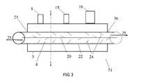
- FIG. 3illustrates a side view of one embodiment of a heat exchanger of the present invention.
- FIG. 4is a top view of one embodiment of a device of the invention.
- FIG. 5is a depiction of a front view of the system.
- FIG. 6is a side view of an illustrative embodiment of the device of the disclosed invention when the lumen is filled with particles in gaseous state.
- FIG. 7is a cross-sectional view of the illustrative embodiment in FIG. 6 .
- FIG. 8is a side view of an illustrative embodiment of the device of the disclosed invention as temperatures are reduced to a freezing point of the particular gas selected.
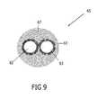
- FIG. 9is a cross-sectional view of the illustrative embodiment in FIG. 8 .
- FIGS. 10-13are side views of various embodiments of a device of the invention.
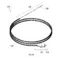
- FIG. 14is an illustrative embodiment of a product of the present invention.
- FIG. 1An external view of a device and system in accordance with one embodiment of the present invention is shown in FIG. 1 .
- the cryogenic system or device 30has sidewalls 17 which form a container 6 that encloses an internal cavity, or lumen 15 .
- the container 6takes the form of a vacuum insulated dewar 6 .
- the dewar 6stores liquid cryogen and interconnects a supply line 11 and return line 12 to a probe or catheter (not shown) to form a closed system 30 .
- the dewar 6may be made of material such as stainless steel or any other material known for providing a vacuum insulated vessel.
- the dewar 6is filled with liquid nitrogen or other liquefied gas (here, discussing as cryogen) to a maximum level 13 .
- liquid nitrogenmay be preferred.
- any fluidic cryogenmay be utilized (e.g. argon, oxygen, helium, hydrogen).
- a submersible pump 1which delivers the liquid cryogen to a sealed pressurization apparatus 40 .
- a valve 2controls the pressure fill into internal open chamber 42 of the pressurization apparatus 40 .
- an immersion heater 44housed in the internal open chamber 42 heats the cryogen to create a desired pressure.
- the liquid nitrogen within the pressurized chamberstarts at a temperature of about ⁇ 196° C. When the heater is activated, it boils the nitrogen within the immediate area. Temperature within internal cavity 42 therefore stays within about ⁇ 196° C. to ⁇ 150° C., more typically in the range of about ⁇ 196° C.
- cryogenis then released through a valve 32 into the baffled linear heat exchanger 4 .
- liquid nitrogenis converted to supercritical nitrogen (SCN) within the pressurization apparatus.
- SCNsupercritical nitrogen
- the SCNis then directed to the heat exchanger for subcooling and tuned to the liquid phase to attain an excess temperature. Thereafter, the SCN can be injected into one or more flexible cryoprobes such that the SCN flows with minimal friction to the tip of the probe.
- the baffled linear heat exchanger 4in one embodiment is surrounded by a subcooling chamber 3 which subcools the pressurized cryogen for delivery to external cryoprobes.
- the subcooling chamber 3in connection with the heat exchanger 4 at an entrance 23 and an exit opening 36 form an integral unit 51 for supplying subcooled liquid cryogen.
- the subcooled cryogenpasses into a supply line 11 and continues out through an exit port 35 and through a control valve 14 where various configurations of cryoprobes are attached.
- the subcooling chambermay attach a vent line to any of the vents 8 , to a supply connecting line 19 controlled through a valve 27 , or to a vacuum line 16 through a control valve 7 which is connected to a vacuum pump 18 .
- the cryogenis returned (as demonstrated by the arrows in FIG. 1 ) from the cryoprobe via a return tube 12 into a return chamber/cylinder 5 of the dewar 6 .
- the return tube 12connects into the return cylinder 5 which also surrounds the supply tube 11 that exits the heat exchanger 4 .
- One or more exit ports 35may be included in a side wall 17 of the dewar 6 or may be a separate unit 14 to incorporate various control valves.
- the device 30is filled through a supply port 29 and then sealed to form a closed system, thereby allowing for the supply, return, collection, and re-utilization of liquid cryogen during its utilization in the medical/surgical field.
- the entire system 30may or may not be pressurized during operation.
- the systemmay also be vented to the surrounding environment to prevent excess pressure buildup during operation.
- the returning cryogenempties into the return cylinder or chamber 5 .
- the returning cryogenmay empty as bulk fluid into the internal lumen 15 within the dewar 6 .
- the linear heat exchanger 4subcools the liquid cryogen prior to delivery to tissue.
- the linear heat exchanger 4is an inner chamber 4 which passes through subcooling chamber 3 and is connected via the entrance 23 and exit opening 36 . Liquid cryogen passing through the inner chamber 4 is reduced in temperature to a subcooling degree by the outer subcooling chamber 3 .
- the chamber within a chamber configurationincludes a subcooling vacuum chamber 3 filled with liquid cryogen upon which a vacuum 18 is drawn through valve-controlled port 9 to reduce the atmospheric pressure on the cryogen. The temperature of the cryogen within the subcooling chamber 3 can then be reduced even further.
- the subcooling chamber 3also comprises valve controlled ports 8 external to the maximum liquid cryogen level for monitoring and electronically controlling temperatures, pressures, and flow rates of liquid cryogen passing through the subcooling unit.
- a vacuum 18can be drawn on vacuum line 16 at a controlled internal valve 7 or external valve 9 .
- valve controlled ports 8may be accessible for delivery of liquid cryogen to the subcooling chamber 3 by way of a supply line 19 or as a vent 8 for any excessive gas coming from the subcooling chamber 3 .
- the vacuum 18also is attached to the cryoprobe(s) by way of vacuum line 39 .
- FIGS. 2 and 3illustrate side views of different aspects of a linear baffled heat exchanger 4 and subcooling unit 3 as an integral unit 51 .
- An interior central component or spiral 20 within the interior lumen of the chamber 4operates like a corkscrew to increase the flow path 25 of the liquid cryogen.
- An outer wall 22 of the inner chamber 4also comprises baffles 24 which increase the surface area in the heat exchanger for quicker and reduced cooling of the liquid cryogen.
- a series of baffles 24emanate into the flow path 25 (as illustrated by arrows) of the cryogen in the inner lumen, thereby increasing the surface area in the heat exchanger 4 .
- the spiral componentmay be any size and shape as to efficiently increase the flow of liquid cryogen. Planar structures, as described below, or any additional features included to increase surface area may be incorporated or substituted.
- FIG. 3illustrates another embodiment of a linear heat exchanger 4 such that the internal structure 20 has a planar configuration and also operates in a circular motion to increase the flow 25 of the liquid cryogen.
- An internal structure 20assists in circulating the flow of liquid cryogen through the interior lumen of the chamber 4 , possibly with an interconnected tubular unit that would allow radial movement of internal structure 20 .
- One embodiment of the medical devicecomprises a return chamber 5 which is illustrated as a return cylinder 5 in FIG. 1 such that the return chamber 5 surrounds the supply line 11 coming from the heat exchanger 4 .
- the return chamber 5 and the surrounded supply linemay then provide a secondary heat exchanger for the system/medical device 30 .
- Cryogen returnis vented into the return chamber 5 .
- the return chamber 5comprises a series of vent holes 26 near the top of the return chamber 5 to allow for the venting of gas and/or liquid overflow into the main dewar 6 . Vent holes 26 allow for the reutilization of cryogen and thus extend the operation time for the medical device 30 .
- the return tube 12is vented into the main dewar 6 either directly or by first passing through a linear heat exchanger (similar to the combination of heat exchanger 4 and subcooling chamber 3 ) to subcool the return cryogen prior to venting into the main dewar 6 .
- a linear heat exchangersimilar to the combination of heat exchanger 4 and subcooling chamber 3
- Return of the cryogen to the main dewar 6allows the cryogen to return through a heat exchanger such that the cryogen is reutilized and extends the operation time even longer.
- the medical device 30may provide a system which is controlled through a series of computer controlled valves including any heaters, sensors, motors, or gauges.
- the sensorscontrol and monitor pressure, temperature, and fluid level in the dewar, and can measure any metric as may be desired.
- the sensorsmonitor pressure levels within defined safety ranges.
- the sensorsmay control the pressurization of one or more components internal to the dewar. Any of the valves 2 , 7 , 8 , 9 , 27 or 32 including exit portal valve 14 , may be automated to enable a controlled and consistent operation of the cryogenic system (e.g. computer controlled operation through the electronically controlled valves).
- FIG. 4An embodiment of a system 50 is shown in FIG. 4 .
- a series of six pulsatile pressurization chambers 40are sealed chambers/cylinders 40 within dewar 6 of the closed system 50 .
- liquid cryogenin pumped to the pulsatile pressurization chambers 40 which then delivers liquid cryogen in a continuous series of bursts to the heat exchanger 4 .
- the baffled linear heat exchanger 4provides an enhanced subcooling of the pressurized liquid cryogen while also incorporating an integral subcooling unit 3 .
- the chambers 40each comprising an individual immersion heater 44 , can then sequentially deliver liquid cryogen at consistent rates, or as specifically determined rates, to the heat exchanger 4 .
- the subcooled cryogenpasses into a supply line 11 and continues out through an exit port 35 where a control valve 14 is positioned and various configurations of cryoprobes are attached.
- the cryogenis returned (as demonstrated by the arrows in FIG. 4 ) via a return tube 12 from the cryoprobe to the dewar 6 into a return cylinder 5 .
- the return tube 12connects into the return cylinder which surrounds the supply tube 11 that exits the heat exchanger 4 .
- the entire system 50may or may not be pressurized during operation.
- the deviceis also vented through vent ports 8 to the surrounding environment to prevent excess pressure buildup during operation.
- a cryogenic system 50has been filled and detached from its cryogenic fill tank.
- the system 50is a separate mobile unit protected and contained entirely within an enclosed console for easy access and mobility. Once the system has been sealed, the cryogenic supply can be maintained for several procedures. The reutilization of the liquid cryogen provides a time savings and cost-efficient model for cryotherapeutic and cryosurgical procedures.
- the system 50can be further utilized for any process requiring rapid cooling.
- the system 50comprises a submersible liquid nitrogen pump 1 connected to a supply line 11 which directs the liquid nitrogen into a supply manifold 33 .
- the supply manifold 33routes the liquid nitrogen into at least one pulsatile pressurization chamber 40 where the liquid cryogen is heated.
- the pressurized liquid cryogenhere, liquid nitrogen
- the pressurized liquid cryogenthen starts filling the next pressurization cylinder/chamber 40 in the series such that when one chamber 40 is filling, another can be simultaneously pressurized and prepared for use. This permits a wave of activity through the cylinders so that it can cycle through each step of system operation.
- the pressurized cryogenAs the pressurized cryogen is delivered to the heat exchanger 4 , and passes the subcooled pressurized cryogen out through the supply line 11 through the exit port 35 and into the attached cryoprobes, another pressurization chamber is filled and pressurized.
- the simultaneous use and pressurization of the liquid cryogenprovides for the sequential delivery of liquid cryogen in a continuous series of pulsations to a cryogenic instrument or probe.
- Each pressurization apparatus 40comprises a pressure valve controlled inlet 52 , valve controlled outlet 54 , and vent ports as may be desired, as well as an immersion heater 44 .
- the filling of the pressurization apparati 40is controlled through a series of pressure valves 52 on the supply manifold 33 .
- Liquid cryogenis heated within each pressurized apparatus. Pressurized liquid cryogen is then released through the control valve 54 to an outlet port/opening 46 of an outlet manifold 34 to the supply line 11 , and delivered to a baffled linear heat exchanger 4 .
- a subcooling unit 3surrounds the heat exchanger 4 for more rapid cooling.
- the cryogenic device 50comprises six pressurized apparati 40 linked together. Other embodiments, however, may comprise any number of pressurized apparati 40 individually or linked together in combination. The apparati can then be controlled individually or in sequence to deliver pressurized liquid cryogen to the heat exchanger 4 .
- one or more pressurization apparati 40may be arranged to supply one or more cryoprobes. Further, the series of pressurized apparati 40 may be interconnected with another series of apparati 40 .
- six pulsatile pressurization chambers 40are housed within a support network of a console.
- three of the cylinders within one-half of the dewarsimultaneously fill while three cylinders within the other half of the dewar deliver cryogen out through the outlet manifold.
- Liquid cryogenis heated in the sealed pressurization chambers 40 . Pressure is increased to a specified level in the sealed pressurization chambers 40 , and then the pressurized cryogen is controllably released into a heat exchanger 4 to subcool the cryogen.
- a subcooling vacuum chamber 3surrounds the heat exchanger 4 , facilitating the delivery of subcooled cryogen to an attached cryoprobe (also referred to as probe or catheter).
- a sensor within the heat exchangermonitors the temperature and pressure of the subcooled cryogen passing into supply line 11 as it continues out through an exit port 35 where various configurations of cryoprobes are attached.
- the systemmay fill or discharge each cylinder 40 individually, any simultaneous fill or discharge, or rate of fill or discharge, may be incorporated into the system.
- the closed systemkeeps a constant supply of liquid nitrogen available for delivery to the cryoprobe and provides a more immediate and rapid rate of cooling for cryotherapeutic procedures. It is therefore possible to close the supply port 29 where supply tanks fill the dewar (See FIG. 1 and FIG. 4 ) and move the system to any locale or setting.
- the supply valve 2may be closed and the release valve 14 opened to create a flow of liquid cryogen to the cryoprobe.
- Various arrangements of valves and sensorsmay therefore provide for similar flow.
- the pressurized chambers 40are filled and the dewar sealed.
- a single drive pump 1perpetuates directional flow of the cryogen into the pressurization chambers.
- all chamberscan be filled through various configurations of single direction pumping.
- a reversible pump and fill methodallows one pressurized chamber 40 to fill and then the pump 1 flips or reverses functionality to fill another pressurized chamber. This process can be repeated to fill any number of chambers.
- pressurized chambers 40are enclosed completely within the dewar 6 .
- any arrangement of the pressurized cylindersis possible so long as the closed system provides for the pulsatile delivery of cryogen to the cryoprobe.
- any single or multiple configurations of cryoprobes or cathetersmay be used.
- Such instrumentsmay also include cryoguns or cryodevices for rapid cryo-delivery processes or cryotherapies.
- the machinery and components of the operational systemare housed in a console 210 to which the cryocatheters/cryoprobes 265 are attached to form the complete system 200 .
- SCNsupercritical nitrogen
- an immersible liquid cryogen pump 201Upon filling the dewar 206 with liquid nitrogen from an external source, an immersible liquid cryogen pump 201 is activated to fill each cryogen supply cylinder 202 a & 202 b, or cartridge, sequentially. Initially, one cartridge 202 a is filled along with its linked cryogen pressurization cartridge 203 a. Cryogenic solenoid valves 204 (a and b) provide venting of the gas within the cartridge assembly to support filling.
- Manifolds 208(typically metal, stainless steel or aluminum) provide access points into the cartridges/cylinders 202 , 203 . The manifolds comprise components such as a heater, thermocouple, and the vent lines that pass through to the cylinders 202 , 203 .
- the SCNBy converting liquid nitrogen to SCN in a cartridge cooled by atmospheric liquid nitrogen ( ⁇ 196° C.), the SCN is subcooled and tuned to the liquid phase, attaining an excess temperature (i.e. the ability to absorb heat without boiling) of approximately 50° C.
- the SCNWhen the SCN is injected into the flexible cryoprobe, the SCN flows with minimal friction to the tip of the probe (boiling chamber). In the tip, SCN pressure drops due to an increased volume and outflow restriction, heat is absorbed (nucleate boiling) along the inner surface of the TIP, micro bubbles of nitrogen gas condense back into a liquid, and the warmed SCN reverts to pressurized liquid nitrogen as it exits the return tube and resupplies the dewar containing atmospheric liquid nitrogen.
- This flow dynamicoccurs within a few seconds and is regulated by a high pressure solenoid valve 204 .
- the processis repeated with the second cartridge subassembly ( 202 b & 203 b ).
- liquid nitrogenhas been overcome by developing a novel device to convert atmospheric liquid nitrogen to supercritical nitrogen.
- the current system herein describedallows for rapid delivery of liquid cryogens through very small tubing of the cryo-instrument 265 .
- the SCNcan be injected or drawn through two plus meters of hypodermic tubing without boiling, thereby resulting in near instantaneous ice formation at the tip to target site specific ablation of tissue as well as the creation of transmural lesions without the formation of a thrombus or aneurysm.
- Supercritical nitrogenis a dense fluid with properties of both gas and liquid that can be tuned toward one phase or the other.
- SCNIn the liquid phase, SCN lacks surface tension and transports without friction.
- This cryoenginewhich operates as a cryogen generator, produces SCN in the liquid phase with a boiling point of about ⁇ 149° C. which is subcooled by the surrounding atmospheric liquid nitrogen to about ⁇ 196° C.
- the SCNpasses instantly through the system without the phase transition to a gas due to both the frictionless flow and the subcooling which compensates for parasitic heat gain along the path.
- the embodiment of FIG. 5may be utilized in any supercooling system or in directing flow of liquid cryogen through to a cryo-instrument. The supercritical point will be determined by the chemistry of the specified liquid or gas used. Therefore, the system can be adjusted to accommodate for differences in chemistry.
- a catheter/probe assembly 265is connected to the cryoengine of FIG. 5 .
- FIG. 6 and FIG. 7An external view of a device 65 in accordance with one embodiment of the present invention is shown in FIG. 6 and FIG. 7 .
- the device 65 of an embodimenttakes the form of a catheter having a tube within a tube configuration, and forming the longitudinal body 65 .
- the longitudinal body 65comprises internal tubes, including a supply line 62 and a return line 63 , contained within an outer insulation tube 61 and continuously running through the length of the tubular shaft 60 of the longitudinal body 65 .
- the outer insulation tube 61 , or outer catheter sheath 61defines the size, shape, and dimensions of the longitudinal body 65 which conforms to dimensions that are capable of housing the internal lines 62 , 63 .
- the tubular shafttherefore extends from a proximal end 51 of the longitudinal body 65 to a distal end or tip 68 .
- the outer catheter sheath 61provides a unitary support structure for the flow of cryogen to and from the distal end of the catheter tip 68 ; desirably, the distal end is where a freezing event is initiated.
- the cryogen utilized in one embodimentmay be liquid nitrogen. In another embodiment, supercritical nitrogen is utilized. Any desired liquid cryogen may be utilized, however, and the system adjusted to accommodate for different chemistries and phases of matter.
- the inner supply line 62 and return line 63are maintained in the center of the outer sheath 61 by open configuration insulative spacers 53 placed throughout the catheter 65 .
- the open configurationallows for a catheter lumen 64 to be filled with gas.
- the outer catheter sheath 61is sealed to the connector 66 to create the gaseous lumen 64 .
- the tip 68in combination with the inner supply line 62 and the return line 63 come into contact with the outer sheath 61 at the distal end to develop a freezing region.
- the shaft 60 of the catheter 65is flexible, as facilitated by a deflection wire 67 that runs along the shaft 60 , the shaft of which is insulated by a temperature induced vacuum.
- the deflection wire 67is a control line that runs down the shaft 60 to the tip of the catheter 65 to allow the catheter tip 68 to be moved on an angle, in a finger-like motion to steer and direct the catheter/probe 65 to the target tissue.
- the deflection wire 67guides the device 65 and monitors environmental measures of temperature, pressure, and/or physiological conditions.
- the guide 67may integrate individual components and sensors such as an optical imaging component in connection with the guide or any number of thermocouples, pressure transducers, electrocardiogram monitors, or other electrophysiological sensors, alone or in combination.
- insulative foame.g. styrofoam, plastics, rubberized materials or other such insulative compositions
- insulative foame.g. styrofoam, plastics, rubberized materials or other such insulative compositions
- Various aspects of the inventionaccommodate a catheter tip 68 as designed to be steerable and deflectable to allow for guided targeting to the desired tissue site.
- spacers or insulative foammay be utilized to prevent internal supply and return lines from contacting the outer sheath.
- any freeze zonecan be produced as designated by the configurations of catheter tips 68 . (See FIGS. 10-13 ).
- a condensation based vacuum insulationis temperature dependent and located in the catheter 65 .
- a process of physically marking or chemically etching the surfaces 69enhances nucleation and physical vaporization deposition of saturated gas.
- the surfacemay be roughened, sprayed with any number of powder-like substances like silica, metallic particles and/or a carbon coating.
- the lumen 64 within the outer sheath 61is filled with select vapors, or non-equilibrated phase change gas 64 .
- butanewhich remains in a gaseous state at about room temperature, between about 0° C. to about 37° C. (See FIGS. 6 , 7 ), but solidifies into crystalline deposits 52 upon chilling to below about 0° C., and simultaneously deposits a film of crystals in a controlled deposition process upon the designated surfaces 69 (See FIGS. 8 , 9 ).
- temperature variationsare dependent upon the type of vapors utilized, chemical characteristics and variations of vapor combinations. Therefore, temperatures of varying gases may be selectively controlled so as to create the same or similar effect of spontaneous nucleation and simultaneous deposition upon reaching a freezing temperature.
- one embodimentmay interconnect a vacuum line of a cryosystem console with the catheter or probe 65 through a vacuum port 55 of the connector 66 as illustrated in FIGS. 6 and 7 .
- the vacuumis formed upon sealing the lumen at the connector and mechanically drawing a vacuum through vacuum port 55 .
- the vacuum portmay connect via its own vacuum system or in combination with the vacuum pump of the cryosystem.
- a dual insulative barriercan be created in the present invention by either a mechanically drawn vacuum or a spontaneously induced vacuum [via temperature inducement] (the vacuum itself creating the insulation for the internal tubes) in combination with a nucleation enhanced surface modification to enhance deposition of gas crystals onto the designated outer surfaces of the internal tubes.
- the outer walls of the internal tubesare physically or chemically etched at designated sites along the tubular shaft. A region within the distal end or tip 8 can then be configured specifically designated freeze zones.
- nucleation/ sublimation in combination with a deposition processforms solid crystals along the supply line 62 and return line 63 outer walls, and spontaneously results in an evacuated space within the lumen 64 .
- the evacuated spaceacts as an insulative barrier between the outer catheter sheath and the frost encased inner lines 62 , 63 .
- Film wise deposition along a length of the surfaces 69 of the supply line 62 and return line 63results in crystalline film deposits of low thermal conductivity.
- the depositionmay coat a portion of the outer surfaces or the entire outer surfaces of the inner lines to run the entire length of the internal tubes. (Note: The ‘x’ marks in FIGS.
- FIGS. 8 , 9demonstrate the nucleation enriched supply and return tubular surfaces 69 , the tubular surfaces of which are modified by processes described herein.
- the non-solidified gas crystals 54 , non-equilibrating phase change gas particles 54are illustrated in FIG. 7 .
- Nucleated or solidified particles, as designated by “*”are depicted in FIGS. 8 , 9 upon the modifications “x” (etching) on the surfaces 69 .
- the nucleated particles 52(marked as “*”) are formed when the gas reaches a freezing temperature.
- any pressuremay be utilized.
- pressure in the devicemay be maintained or controllably elevated or reduced.
- gasmay be maintained at atmospheric or high pressure to support the retention of the vapor state at room temperature.
- gasas either a pure component or as a mixture of various components.
- gaseous compositionsfor exemplary purposes only and not limitation, may comprise butane, carbon dioxide, iodine, camphor, and/or nitrous oxide.
- an enhanced nucleation surface 69 on inner tube/line 62 , 63 surfacesmay result where a process includes treating the walls of the inner lines 62 , 63 to match nucleating efficiency with the chemical characteristics of the gas to be deposited (e.g. marking the surfaces with impurities, utilizing silica, or other powderized material, chemically coating or etching) and thereby create a similar effect.
- Embodiments of the present inventionmanipulate the structural configurations of the tips 68 , as illustrated in FIGS. 10-13 .
- the freeze zoneis created where the internal components 62 / 63 contact the outer sheath 61 at a distal end 68 .
- a distal end 100 in FIG. 10includes a closed loop coiled supply tube 106 in contact with the outer sheath 61 to affect a cold sink.
- the supply line 62 and return line 63convene at the freezing zone of the tip in the formation of a coil 106 .
- a metallic balloon tip 107is illustrated in which cryogen is circulated in the tip and then returned.
- the supply line 62extends to a distance into the tip 68 beyond the extension of return line 63 such that cryogen pumped into the balloon-like tip 107 circulates within the sealed confines of the inflated region when the catheter is engaged for the procedure.
- the supply line 62can extend any length or distance into the tip.
- the balloon-like tipmay be composed of any flexible or rigid material including metallic, plastic, or ceramic compositions.
- the balloon-like structure within the sheathmay cause the outer sheath 61 to inflate and deflate for cryogenic procedures.
- cryogenic procedures performed within a vesselmay advantageously make use of an inflatable cryogenic element 107 at the distal end of the probe so that the outer sheath expands as the internal inflatable cryogenic element expands.
- the inflatable tip 107is a sealed within the distal portion 68 in connection with both an individual supply line 62 and an individual return line 63 .
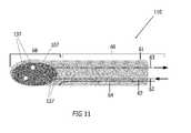
- the embodiment of the distal end 110is included in the length of the longitudinal tube and has a distal tip 68 which serves as the freezing region in connection with the tubular shaft 60 (only a portion of which is illustrated here in FIG. 11 ) (i.e. In the embodiment shown in FIG. 14 , a distal end 128 can be replaced with distal end 110 .)
- a sealed interface 127ensures that the inflatable area can expand and contract in correspondence with the fill and removal of the cryogenic medium.
- the cryogenic mediumin one embodiment in liquid nitrogen.
- the inflatable structurehere, a metallic balloon tip
- the inflatable structureis designed and configured with materials that conform to the use of liquid nitrogen. Without considering the type of cryogen utilized, the inflatable tip may rupture or create undesired effects.
- the tip of the present embodimentis designed to meet the needs of a system and device utilizing liquid nitrogen.
- the sealed interface 127may be a wall or connection component (not illustrated) which seals the freezing region 68 of the tip away from the tubular shaft 60 in a blunt-tip probe.
- the sealed interfaceallows a supply line 62 and a return line 63 to access the freezing tip, the open ends 137 of which allow cryogen to be dispersed within the sealed zone 68 .
- the sealed zoneis the balloon tip, but any size or shape of sealed zone may be utilized in different aspects of the present invention to create similar results.
- the open-ended supply linein one embodiment extends further into the sealed zone toward the distal end and beyond the open end of the return line. Any length of supply line or return line, however, may be utilized; the lengths may be designed having equal lengths or different lengths, as desired.
- FIG. 12is another embodiment of the probe tip/distal end 155 which illustrates a closed loop tip 118 .
- the closed loop tipintegrally connects both supply line 62 and return line 63 to form a unitary structure for delivery and return of liquid cryogen to the distal end in the freezing region of the probe.
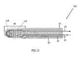
- FIG. 13illustrates a cryoprobe 165 as a closed loop tip with a finned heat exchanger 119 within the freezing zone or tip 68 .
- the heat exchangerprovides for a more efficient heat extraction from the tissue, thereby providing faster cryotreatment and greater injury/freezing to the tissue site.
- the heat exchangeris also utilized to cool the cryogen prior to return to the console, resulting in increased cryogen recovery.
- Other variations in tip designmay be any size and dimension or take the size or shape of known catheters or probes 65 in the field.
- cryoprobesare utilized to ablate the target tissue.
- catheters or surgical probesare utilized in the cryoablation procedure. Further configurations of the cryoprobe as described infra may also accommodate other structural variations.
- the product for performing cryotherapeutic proceduresis illustrated as an elongated body 175 , about six feet in length.
- a connector 116 at a proximal end 121allows the cryoprobe to be connected with a cryogenic delivery system 200 (see FIG. 5 ).
- the freezing region, or tip 138is position within the distal end 128 with a flexible tubular shaft 120 positioned between the ends.
- FIGS. 10-13Some of the various embodiments of distal end 128 have been depicted in FIGS. 10-13 , embodiments of distal ends 100 , 110 , 155 , 165 which can serve as replacements for the distal end 128 within the elongated product 175 .
- the support structure 175comprises an outer sheath (as illustrated in FIGS.
- the product 175When in use and hooked to a cryogenic delivery system, the product 175 simultaneously produces an insulative vacuum throughout the tubular shaft 120 .
- a dual insulative barrieris formed by a temperature initiated transient vacuum in combination with an enhanced nucleation deposition process along the outer surface of the internal tubes (discussed infra). The nucleation sites are therefore capable of selective placement anywhere throughout the product.
- the distal end 128is a needle-like probe end. In another embodiment, the distal end 128 takes the form of a blunt-tip probe end.
- the distal portion 128may be integral with the tubular shaft or be removably placed in connection therewith. The interconnections of proximal connector, tubular shaft, and distal probe ends thus determines whether or not the individual parts, alone or in combination, may be reused, or disposed of. Further, the length of the distal end 28 may vary according to treatment procedure and may be any size, shape and dimension to correspond to the tissue treated.
- the inventionfacilitates other improvements in cryotherapy, and medical devices or components associated with the treatment.
- the medical device of the inventionallows for the circulation (cooling, delivery, and return) of liquid cryogen to a cryoprobe for the freezing of targeted tissue.
- the inventionfacilitates the eradication of tissue and can thereby decrease hospitalization time; further advantages reduce postoperative morbidities, shorten return to daily functions and work, and further lessen the overall treatment cost.
- the device of the inventionrepresents an approach in the development of cryosurgical devices by allowing for temperature induced transient vacuum insulation along the shaft of a cryoprobe or catheter; including insulating the shaft of a cryoprobe or catheter and delivery of cryogen in targeted thermal therapy. Furthermore, the device has been developed to couple the temperature initiated vacuum with that of a surface modification along the inner tubes to enable enhanced nucleation and deposition of the saturated gas on the surface of the inner tubes and create an additional layer of insulation. In one aspect, the device of the invention allows for the enhanced deposition on the outer surface of the inner tubes through modification of the tube surface, thereby creating an additional insulation barrier. In another aspect, the saturated gas filled lumen of the outer tube at ambient temperature may be either elevated or at atmospheric pressure.
- the cryoprobe device in the inventionmay be of any size, shape, or dimension.
- the devicemay be single use disposable or a multi-use/reusable part (and capable of being sterilized between individual patient treatments).
- the longitudinal bodyextends up to about 6-8 feet or more. Any length, however, may be utilized as designed for particular therapies and treatments. Dimensions less than 12 inches, however, may also be better suited where attached tubing, removable, detachable, or disposable parts are integrated in the design.
- cylindrical or alternative structural designsmay be utilized in the cryogenic system for improved catheter/probe access to a tissue target.
- any rearrangement of the tubes/lines in combination with the components of the above systemmay take many forms and be of any size, shape, or passageway.
- the embodiments of the present inventionare for exemplary purposes only and not limitation.
- this devicerepresents an important step in targeted thermal therapies.
- Various cryosurgical devices and procedures to apply freezing temperatures to a target tissuemay be employed for use with the medical device of the present invention.
- the medical system disclosed hereinhas been developed to enable and improve some of the approaches used to target or ablate tissue.
- the medical devicecan couple controlled pumping of a liquid cryogen through a baffled linear heat exchanger to decrease the overall temperature of the cryogen providing a greater heat capacity of the fluid and thereby resulting in an increased cooling potential in a cryoprobe.
- the mechanical and electrical mechanisms of the operational deviceis contained within a console, a shell or enclosure that allows the system to be easily transported.
- the enclosuremay then include any mobile feature such as wheels, handles, and fixtures (or allow placement onto a cart having these features) so that the system can be transported to and from the location of treatment.
- Such mobilityallows the system to be easily moved to and from an operating room or site of therapeutic treatment.
- the systemis readily separable from the cryogen fill tanks and fill lines that initially supply the system with the liquid nitrogen or other such cryogenic fluid at the supply port 29 (As shown in FIG. 1 ). This improved feature eliminates the bulkiness of standard cryogenic medical devices.
- the multiple embodiments of the present inventionoffer several improvements over standard medical devices currently used in cryogenic industry.
- the improved cryogenic medical devicesremarkably enhance its utilization for the cooling, delivery and return of a liquid cryogen to a cryoprobe for the freezing of targeted tissue.
- the present inventionprovides cost savings and significantly reduced treatment times which further reduce expenditures in the healthcare setting.
- the previously unforeseen benefitshave been realized and conveniently offer advantages for the treatment of multiple disease states.
- the improvementsenable construction of the device as designed to enable easy handling, storage, and accessibility. Further uses of the system outside of the healthcare setting are foreseeable. Potential uses in the space industry, defense systems or any industry requiring rapid cooling may incorporate the cryogenic system as thus described.
- the devicemay include any unitary structure, vessel, device or flask with the capacity to integrally incorporate any combination of such structures.
Landscapes
- Health & Medical Sciences (AREA)
- Surgery (AREA)
- Nuclear Medicine, Radiotherapy & Molecular Imaging (AREA)
- Life Sciences & Earth Sciences (AREA)
- Engineering & Computer Science (AREA)
- Medical Informatics (AREA)
- Biomedical Technology (AREA)
- Heart & Thoracic Surgery (AREA)
- Otolaryngology (AREA)
- Molecular Biology (AREA)
- Animal Behavior & Ethology (AREA)
- General Health & Medical Sciences (AREA)
- Public Health (AREA)
- Veterinary Medicine (AREA)
- Mechanical Engineering (AREA)
- General Engineering & Computer Science (AREA)
- Thermotherapy And Cooling Therapy Devices (AREA)
- Surgical Instruments (AREA)
Abstract
Description
Claims (18)
Priority Applications (1)
| Application Number | Priority Date | Filing Date | Title |
|---|---|---|---|
| US13/061,171US8784409B2 (en) | 2008-09-03 | 2009-11-02 | Cryogenic system and method of use |
Applications Claiming Priority (4)
| Application Number | Priority Date | Filing Date | Title |
|---|---|---|---|
| US9391608P | 2008-09-03 | 2008-09-03 | |
| US9824408P | 2008-09-19 | 2008-09-19 | |
| PCT/US2009/062928WO2010028409A1 (en) | 2008-09-03 | 2009-11-02 | A cryogenic system and method of use |
| US13/061,171US8784409B2 (en) | 2008-09-03 | 2009-11-02 | Cryogenic system and method of use |
Related Parent Applications (3)
| Application Number | Title | Priority Date | Filing Date |
|---|---|---|---|
| US12/553,005ContinuationUS9408654B2 (en) | 2008-09-03 | 2009-09-02 | Modular pulsed pressure device for the transport of liquid cryogen to a cryoprobe |
| US12/562,301ContinuationUS8439905B2 (en) | 2008-09-03 | 2009-09-18 | Nucleation enhanced surface modification to support physical vapor deposition to create a vacuum |
| PCT/US2009/062928A-371-Of-InternationalWO2010028409A1 (en) | 2008-09-03 | 2009-11-02 | A cryogenic system and method of use |
Related Child Applications (1)
| Application Number | Title | Priority Date | Filing Date |
|---|---|---|---|
| US14/336,317ContinuationUS20150018810A1 (en) | 2008-09-03 | 2014-07-21 | Cryogenic system and method of use |
Publications (2)
| Publication Number | Publication Date |
|---|---|
| US20110152849A1 US20110152849A1 (en) | 2011-06-23 |
| US8784409B2true US8784409B2 (en) | 2014-07-22 |
Family
ID=43897016
Family Applications (2)
| Application Number | Title | Priority Date | Filing Date |
|---|---|---|---|
| US13/061,171Active2032-01-21US8784409B2 (en) | 2008-09-03 | 2009-11-02 | Cryogenic system and method of use |
| US14/336,317AbandonedUS20150018810A1 (en) | 2008-09-03 | 2014-07-21 | Cryogenic system and method of use |
Family Applications After (1)
| Application Number | Title | Priority Date | Filing Date |
|---|---|---|---|
| US14/336,317AbandonedUS20150018810A1 (en) | 2008-09-03 | 2014-07-21 | Cryogenic system and method of use |
Country Status (5)
| Country | Link |
|---|---|
| US (2) | US8784409B2 (en) |
| EP (1) | EP2330995B1 (en) |
| CA (1) | CA2736221C (en) |
| ES (1) | ES2551324T3 (en) |
| WO (1) | WO2010028409A1 (en) |
Cited By (17)
| Publication number | Priority date | Publication date | Assignee | Title |
|---|---|---|---|---|
| US10045817B2 (en) | 2010-11-16 | 2018-08-14 | Tva Medical, Inc. | Devices and methods for forming a fistula |
| US10603040B1 (en) | 2015-02-09 | 2020-03-31 | Tva Medical, Inc. | Methods for treating hypertension and reducing blood pressure with formation of fistula |
| US10646666B2 (en) | 2014-08-27 | 2020-05-12 | Tva Medical, Inc. | Cryolipolysis devices and methods therefor |
| US10695534B2 (en) | 2014-03-14 | 2020-06-30 | Tva Medical, Inc. | Fistula formation devices and methods therefor |
| US10821217B2 (en) | 2013-03-14 | 2020-11-03 | Tva Medical, Inc. | Fistula formation devices and methods therefor |
| US10869717B2 (en) | 2012-10-11 | 2020-12-22 | Tva Medical, Inc. | Devices and methods for fistula formation |
| US10874422B2 (en) | 2016-01-15 | 2020-12-29 | Tva Medical, Inc. | Systems and methods for increasing blood flow |
| US11026743B2 (en) | 2016-01-15 | 2021-06-08 | Tva Medical, Inc. | Devices and methods for forming a fistula |
| US11285028B2 (en) | 2016-09-25 | 2022-03-29 | Tva Medical, Inc. | Vascular stent devices and methods |
| US11590322B2 (en) | 2016-01-15 | 2023-02-28 | Tva Medical, Inc. | Devices and methods for advancing a wire |
| US11633224B2 (en) | 2020-02-10 | 2023-04-25 | Icecure Medical Ltd. | Cryogen pump |
| US11771486B2 (en) | 2017-01-17 | 2023-10-03 | Corfigo, Inc. | Device for ablation of tissue surfaces and related systems and methods |
| EP4285849A1 (en) | 2022-05-31 | 2023-12-06 | IceCure Medical Ltd. | Cryogenic system with multiple submerged pumps |
| EP4309604A1 (en) | 2022-07-18 | 2024-01-24 | IceCure Medical Ltd. | Cryogenic system connector |
| US12070526B2 (en) | 2020-05-14 | 2024-08-27 | Cpsi Holdings Llc | Cryogenic disinfection system and method |
| US12295645B2 (en) | 2016-01-15 | 2025-05-13 | Tva Medical, Inc. | Systems and methods for adhering vessels |
| US12426934B2 (en) | 2022-02-28 | 2025-09-30 | Icecure Medical Ltd. | Cryogen flow control |
Families Citing this family (51)
| Publication number | Priority date | Publication date | Assignee | Title |
|---|---|---|---|---|
| US7273479B2 (en)* | 2003-01-15 | 2007-09-25 | Cryodynamics, Llc | Methods and systems for cryogenic cooling |
| KR101039758B1 (en) | 2006-04-28 | 2011-06-09 | 젤티크 애스세틱스, 인코포레이티드. | Cryoprotectants for use with therapeutic devices for improved cooling of subcutaneous lipid-rich cells |
| US9132031B2 (en) | 2006-09-26 | 2015-09-15 | Zeltiq Aesthetics, Inc. | Cooling device having a plurality of controllable cooling elements to provide a predetermined cooling profile |
| US8192474B2 (en) | 2006-09-26 | 2012-06-05 | Zeltiq Aesthetics, Inc. | Tissue treatment methods |
| US20080077201A1 (en) | 2006-09-26 | 2008-03-27 | Juniper Medical, Inc. | Cooling devices with flexible sensors |
| US20080287839A1 (en) | 2007-05-18 | 2008-11-20 | Juniper Medical, Inc. | Method of enhanced removal of heat from subcutaneous lipid-rich cells and treatment apparatus having an actuator |
| US8523927B2 (en) | 2007-07-13 | 2013-09-03 | Zeltiq Aesthetics, Inc. | System for treating lipid-rich regions |
| WO2009026471A1 (en) | 2007-08-21 | 2009-02-26 | Zeltiq Aesthetics, Inc. | Monitoring the cooling of subcutaneous lipid-rich cells, such as the cooling of adipose tissue |
| US9408654B2 (en)* | 2008-09-03 | 2016-08-09 | Endocare, Inc. | Modular pulsed pressure device for the transport of liquid cryogen to a cryoprobe |
| US8784409B2 (en) | 2008-09-03 | 2014-07-22 | Endocare, Inc. | Cryogenic system and method of use |
| US9089316B2 (en)* | 2009-11-02 | 2015-07-28 | Endocare, Inc. | Cryogenic medical system |
| US10182859B2 (en) | 2008-09-03 | 2019-01-22 | Endocare, Inc. | Medical device for the transport of subcooled cryogenic fluid through a linear heat exchanger |
| US8603073B2 (en) | 2008-12-17 | 2013-12-10 | Zeltiq Aesthetics, Inc. | Systems and methods with interrupt/resume capabilities for treating subcutaneous lipid-rich cells |
| CA2760610C (en) | 2009-04-30 | 2017-09-19 | Zeltiq Aesthetics, Inc. | Device, system and method of removing heat from subcutaneous lipid-rich cells |
| CA2787374A1 (en) | 2010-01-25 | 2011-07-28 | Zeltiq Aesthetics, Inc. | Home-use applicators for non-invasively removing heat from subcutaneous lipid-rich cells via phase change coolants, and associated devices, systems and methods |
| US8676338B2 (en) | 2010-07-20 | 2014-03-18 | Zeltiq Aesthetics, Inc. | Combined modality treatment systems, methods and apparatus for body contouring applications |
| GB2484114A (en)* | 2010-09-30 | 2012-04-04 | Astrium Ltd | System for the Recovery, Storage and Utilisation of Atmospheric Gas for Use as a Vehicle Propellant |
| US10722395B2 (en) | 2011-01-25 | 2020-07-28 | Zeltiq Aesthetics, Inc. | Devices, application systems and methods with localized heat flux zones for removing heat from subcutaneous lipid-rich cells |
| US20140249610A1 (en)* | 2011-10-07 | 2014-09-04 | Medtronic Ardian Luxembourg S.A.R.L. | Refrigerant cartridges for cryotherapeutic systems and associated methods of making and using |
| US9101343B2 (en)* | 2012-08-03 | 2015-08-11 | Thach Buu Duong | Therapeutic cryoablation system |
| US9078733B2 (en)* | 2012-08-08 | 2015-07-14 | Galil Medical Inc. | Closed-loop system for cryosurgery |
| EP2933585B1 (en)* | 2012-12-14 | 2018-06-06 | Eagle Industry Co., Ltd. | Liquid supply system |
| US9545523B2 (en) | 2013-03-14 | 2017-01-17 | Zeltiq Aesthetics, Inc. | Multi-modality treatment systems, methods and apparatus for altering subcutaneous lipid-rich tissue |
| US20140276698A1 (en) | 2013-03-14 | 2014-09-18 | Medtronic Cryocath Lp | Method and apparatus for cryoadhesion |
| US9844460B2 (en) | 2013-03-14 | 2017-12-19 | Zeltiq Aesthetics, Inc. | Treatment systems with fluid mixing systems and fluid-cooled applicators and methods of using the same |
| US9084590B2 (en)* | 2013-03-14 | 2015-07-21 | Medtronic Cryocath Lp | Device and method for improved safety and efficacy for cryoablation |
| EP2967707B1 (en)* | 2013-03-15 | 2023-11-08 | Varian Medical Systems, Inc. | Cryogenic system and methods |
| US10197221B1 (en)* | 2013-12-27 | 2019-02-05 | Controls Corporation Of America | Air actuated valves switch and software control system for use with cryogenic liquid systems |
| US20150216719A1 (en) | 2014-01-31 | 2015-08-06 | Zeltiq Aesthetics, Inc | Treatment systems and methods for treating cellulite and for providing other treatments |
| US10675176B1 (en) | 2014-03-19 | 2020-06-09 | Zeltiq Aesthetics, Inc. | Treatment systems, devices, and methods for cooling targeted tissue |
| USD777338S1 (en) | 2014-03-20 | 2017-01-24 | Zeltiq Aesthetics, Inc. | Cryotherapy applicator for cooling tissue |
| US10952891B1 (en) | 2014-05-13 | 2021-03-23 | Zeltiq Aesthetics, Inc. | Treatment systems with adjustable gap applicators and methods for cooling tissue |
| US10568759B2 (en) | 2014-08-19 | 2020-02-25 | Zeltiq Aesthetics, Inc. | Treatment systems, small volume applicators, and methods for treating submental tissue |
| US10935174B2 (en) | 2014-08-19 | 2021-03-02 | Zeltiq Aesthetics, Inc. | Stress relief couplings for cryotherapy apparatuses |
| US10125771B2 (en)* | 2014-09-03 | 2018-11-13 | Uchicago Argonne, Llc | Compact liquid nitrogen pump |
| US11154418B2 (en) | 2015-10-19 | 2021-10-26 | Zeltiq Aesthetics, Inc. | Vascular treatment systems, cooling devices, and methods for cooling vascular structures |
| HK1259174A1 (en) | 2016-01-07 | 2019-11-29 | Zeltiq Aesthetics, Inc. | Temperature-dependent adhesion between applicator and skin during cooling of tissue |
| US10765552B2 (en) | 2016-02-18 | 2020-09-08 | Zeltiq Aesthetics, Inc. | Cooling cup applicators with contoured heads and liner assemblies |
| US10555831B2 (en) | 2016-05-10 | 2020-02-11 | Zeltiq Aesthetics, Inc. | Hydrogel substances and methods of cryotherapy |
| US10682297B2 (en) | 2016-05-10 | 2020-06-16 | Zeltiq Aesthetics, Inc. | Liposomes, emulsions, and methods for cryotherapy |
| US11382790B2 (en) | 2016-05-10 | 2022-07-12 | Zeltiq Aesthetics, Inc. | Skin freezing systems for treating acne and skin conditions |
| RU2656508C1 (en)* | 2016-12-06 | 2018-06-05 | Общество с ограниченной ответственностью "ПРОМГАЗ-ТЕХНОЛОГИЙ" | Method of use of a cryogenic dosing micropump |
| US11076879B2 (en) | 2017-04-26 | 2021-08-03 | Zeltiq Aesthetics, Inc. | Shallow surface cryotherapy applicators and related technology |
| CN108478276B (en)* | 2018-06-07 | 2023-10-13 | 海杰亚(北京)医疗器械有限公司 | A minimally invasive steam probe and treatment equipment for tumor treatment |
| CN109350220B (en)* | 2018-07-23 | 2024-10-18 | 山前(珠海)科技有限公司 | Refrigerating equipment |
| WO2020028472A1 (en) | 2018-07-31 | 2020-02-06 | Zeltiq Aesthetics, Inc. | Methods, devices, and systems for improving skin characteristics |
| JP7658967B2 (en) | 2019-12-03 | 2025-04-08 | パシラ クライオテック インコーポレイテッド | Cryogenic pressure stabilization |
| CN112696655B (en)* | 2021-02-03 | 2022-11-22 | 重庆卓旺科技有限公司 | Steam gas storage device for electric steam generating device |
| CN114460132B (en)* | 2022-02-22 | 2024-01-12 | 河北交投路桥建设开发有限公司 | Asphalt mixture phase-change temperature-adjustment evaluation system and method |
| US20240271867A1 (en)* | 2023-02-09 | 2024-08-15 | Polarean, Inc. | Cryo-collection systems and related methods and hyperpolarizer systems |
| US20250090215A1 (en)* | 2023-09-20 | 2025-03-20 | Varian Medical Systems, Inc. | Apparatuses and methods for cryogen measurement and control for cryoablation systems |
Citations (45)
| Publication number | Priority date | Publication date | Assignee | Title |
|---|---|---|---|---|
| US3794039A (en) | 1969-10-25 | 1974-02-26 | Linde Ag | Apparatus for cryosurgery |
| US4082096A (en) | 1973-12-10 | 1978-04-04 | Benson Jerrel W | Cryosurgical system |
| US4377168A (en) | 1981-02-27 | 1983-03-22 | Wallach Surgical Instruments, Inc. | Cryosurgical instrument |
| US4829785A (en) | 1987-12-04 | 1989-05-16 | The Boeing Company | Cryogenic cooling system with precooling stage |
| US5147355A (en) | 1988-09-23 | 1992-09-15 | Brigham And Womens Hospital | Cryoablation catheter and method of performing cryoablation |
| US5237824A (en) | 1989-02-16 | 1993-08-24 | Pawliszyn Janusz B | Apparatus and method for delivering supercritical fluid |
| US5334181A (en) | 1990-09-26 | 1994-08-02 | Cryomedical Sciences, Inc. | Cryosurgical system for destroying tumors by freezing |
| US5423807A (en) | 1992-04-16 | 1995-06-13 | Implemed, Inc. | Cryogenic mapping and ablation catheter |
| US5452582A (en) | 1994-07-06 | 1995-09-26 | Apd Cryogenics, Inc. | Cryo-probe |
| US5733280A (en) | 1995-11-15 | 1998-03-31 | Avitall; Boaz | Cryogenic epicardial mapping and ablation |
| US5746736A (en) | 1995-08-09 | 1998-05-05 | Lumedics, Ltd. | Cryogenic laser lithotripsy with enhanced light absorption |
| US5758505A (en) | 1995-10-12 | 1998-06-02 | Cryogen, Inc. | Precooling system for joule-thomson probe |
| US5916212A (en) | 1998-01-23 | 1999-06-29 | Cryomedical Sciences, Inc. | Hand held cyrosurgical probe system |
| US5951546A (en) | 1994-12-13 | 1999-09-14 | Lorentzen; Torben | Electrosurgical instrument for tissue ablation, an apparatus, and a method for providing a lesion in damaged and diseased tissue from a mammal |
| US6096032A (en) | 1996-08-14 | 2000-08-01 | Rowland; Stephen James | Medical cryo-surgical device |
| US6161543A (en) | 1993-02-22 | 2000-12-19 | Epicor, Inc. | Methods of epicardial ablation for creating a lesion around the pulmonary veins |
| US6171301B1 (en) | 1994-04-05 | 2001-01-09 | The Regents Of The University Of California | Apparatus and method for dynamic cooling of biological tissues for thermal mediated surgery |
| US20010021847A1 (en) | 1999-01-25 | 2001-09-13 | Marwan Abboud | Cooling system |
| US6306129B1 (en) | 1997-09-22 | 2001-10-23 | Femrx, Inc. | Cryosurgical system and method |
| US6468269B1 (en) | 1999-03-02 | 2002-10-22 | Nikolai Korpan | Cryogenic system, especially for performing cryosurgical surgery |
| US6468268B1 (en) | 1999-01-25 | 2002-10-22 | Cryocath Technologies Inc. | Cryogenic catheter system |
| US20040215295A1 (en) | 2003-01-15 | 2004-10-28 | Mediphysics Llp | Cryotherapy system |
| US20050090814A1 (en) | 1999-01-25 | 2005-04-28 | Jean-Pierre Lalonde | Cooling system |
| US20050261671A1 (en) | 2001-05-31 | 2005-11-24 | Baust John G | Cryogenic system |
| US20050261753A1 (en) | 2003-01-15 | 2005-11-24 | Mediphysics Llp | Methods and systems for cryogenic cooling |
| US20060079867A1 (en) | 2003-04-03 | 2006-04-13 | Nir Berzak | Apparatus and method for accurately delimited cryoablation |
| US20060129142A1 (en) | 2004-12-15 | 2006-06-15 | Cryovascular Systems, Inc. | Efficient controlled cryogenic fluid delivery into a balloon catheter and other treatment devices |
| US7160291B2 (en) | 2003-06-25 | 2007-01-09 | Endocare, Inc. | Detachable cryosurgical probe |
| US20070021741A1 (en) | 2003-07-11 | 2007-01-25 | Cryocath Technologies Inc. | Method and device for epicardial ablation |
| US7207985B2 (en) | 2003-06-25 | 2007-04-24 | Endocare, Inc. | Detachable cryosurgical probe |
| US20070244474A1 (en) | 2006-04-18 | 2007-10-18 | Sanarus Medical, Inc. | Cryosurgical system |
| US20070277550A1 (en) | 2000-08-09 | 2007-12-06 | Cryocor, Inc. | Refrigeration source for a cryoablation catheter |
| US7306589B2 (en) | 2003-04-24 | 2007-12-11 | Boston Scientific Scimed, Inc. | Therapeutic apparatus having insulated region at the insertion area |
| US20080009845A1 (en) | 2003-06-25 | 2008-01-10 | Endocare, Inc. | Cryosurgical probe with adjustable sliding apparatus |
| US20080027422A1 (en) | 2006-07-25 | 2008-01-31 | Ams Research Corporation | Closed-Loop Cryosurgical System and Cryoprobe |
| US20080147056A1 (en) | 2006-07-14 | 2008-06-19 | Micrablate | Energy delivery systems and uses thereof |
| US7416551B2 (en) | 2003-07-28 | 2008-08-26 | A.F.M. Medical Systems Ltd. | Catheter for delivering a tissue ablation probe |
| US20080255551A1 (en) | 2007-04-16 | 2008-10-16 | Sanarus Medical, Inc. | Cryosurgical System with Low Pressure Cryogenic Fluid Supply |
| US20080300584A1 (en) | 2007-06-01 | 2008-12-04 | Lentz David J | Cryoablation segment for creating linear lesions |
| US20090012510A1 (en) | 2001-12-04 | 2009-01-08 | Endoscopic Technologies, Inc. | Cardiac ablation devices and methods |
| US20090281533A1 (en) | 2008-05-12 | 2009-11-12 | Boston Scientific Scimed, Inc. | Apparatus and method for chilling cryo-ablation coolant and resulting cryo-ablation system |
| US20100057067A1 (en) | 2008-09-03 | 2010-03-04 | Baust John M | Modular pulsed pressure device for the transport of liquid cryogen to a cryoprobe |
| US20100057064A1 (en) | 2008-09-03 | 2010-03-04 | Baust John M | Medical Device for the Transport of Subcooled Cryogenic Fluid through a Linear Heat Exchanger |
| WO2010028409A1 (en) | 2008-09-03 | 2010-03-11 | Dobson, Melissa, K. | A cryogenic system and method of use |
| US20100241112A1 (en) | 2009-03-23 | 2010-09-23 | Boston Scientific Scimed, Inc. | Systems apparatus and methods for distributing coolant within a cryo-ablation device |
Family Cites Families (4)
| Publication number | Priority date | Publication date | Assignee | Title |
|---|---|---|---|---|
| KR0144165B1 (en)* | 1995-05-12 | 1998-07-01 | 문정환 | Improved Manufacturing Method of Inverse Tee (T) Transistor |
| ATE308933T1 (en)* | 2000-06-23 | 2005-11-15 | Cryocath Technologies Inc | DEVICE FOR CRYOTREATMENT |
| US7111380B2 (en)* | 2002-10-31 | 2006-09-26 | Emerson Electric Co. | Method for forming an annular stator assembly |
| US20070149957A1 (en)* | 2005-12-23 | 2007-06-28 | Sanarus Medical, Inc. | Low pressure liquid nitrogen cryosurgical system |
- 2009
- 2009-11-02USUS13/061,171patent/US8784409B2/enactiveActive
- 2009-11-02ESES09812404.3Tpatent/ES2551324T3/enactiveActive
- 2009-11-02WOPCT/US2009/062928patent/WO2010028409A1/enactiveApplication Filing
- 2009-11-02CACA2736221Apatent/CA2736221C/enactiveActive
- 2009-11-02EPEP09812404.3Apatent/EP2330995B1/enactiveActive
- 2014
- 2014-07-21USUS14/336,317patent/US20150018810A1/ennot_activeAbandoned
Patent Citations (55)
| Publication number | Priority date | Publication date | Assignee | Title |
|---|---|---|---|---|
| US3794039A (en) | 1969-10-25 | 1974-02-26 | Linde Ag | Apparatus for cryosurgery |
| US4082096A (en) | 1973-12-10 | 1978-04-04 | Benson Jerrel W | Cryosurgical system |
| US4377168A (en) | 1981-02-27 | 1983-03-22 | Wallach Surgical Instruments, Inc. | Cryosurgical instrument |
| US4829785A (en) | 1987-12-04 | 1989-05-16 | The Boeing Company | Cryogenic cooling system with precooling stage |
| US5147355A (en) | 1988-09-23 | 1992-09-15 | Brigham And Womens Hospital | Cryoablation catheter and method of performing cryoablation |
| US5237824A (en) | 1989-02-16 | 1993-08-24 | Pawliszyn Janusz B | Apparatus and method for delivering supercritical fluid |
| US5334181A (en) | 1990-09-26 | 1994-08-02 | Cryomedical Sciences, Inc. | Cryosurgical system for destroying tumors by freezing |
| US5674218A (en) | 1990-09-26 | 1997-10-07 | Cryomedical Sciences, Inc. | Cryosurgical instrument and system and method of cryosurgery |
| US5423807A (en) | 1992-04-16 | 1995-06-13 | Implemed, Inc. | Cryogenic mapping and ablation catheter |
| US6161543A (en) | 1993-02-22 | 2000-12-19 | Epicor, Inc. | Methods of epicardial ablation for creating a lesion around the pulmonary veins |
| US6171301B1 (en) | 1994-04-05 | 2001-01-09 | The Regents Of The University Of California | Apparatus and method for dynamic cooling of biological tissues for thermal mediated surgery |
| US5452582A (en) | 1994-07-06 | 1995-09-26 | Apd Cryogenics, Inc. | Cryo-probe |
| US5951546A (en) | 1994-12-13 | 1999-09-14 | Lorentzen; Torben | Electrosurgical instrument for tissue ablation, an apparatus, and a method for providing a lesion in damaged and diseased tissue from a mammal |
| US5746736A (en) | 1995-08-09 | 1998-05-05 | Lumedics, Ltd. | Cryogenic laser lithotripsy with enhanced light absorption |
| US5758505C1 (en) | 1995-10-12 | 2001-10-30 | Cryogen Inc | Precooling system for joule-thomson probe |
| US5758505A (en) | 1995-10-12 | 1998-06-02 | Cryogen, Inc. | Precooling system for joule-thomson probe |
| US5733280A (en) | 1995-11-15 | 1998-03-31 | Avitall; Boaz | Cryogenic epicardial mapping and ablation |
| US6096032A (en) | 1996-08-14 | 2000-08-01 | Rowland; Stephen James | Medical cryo-surgical device |
| US6306129B1 (en) | 1997-09-22 | 2001-10-23 | Femrx, Inc. | Cryosurgical system and method |
| US5916212A (en) | 1998-01-23 | 1999-06-29 | Cryomedical Sciences, Inc. | Hand held cyrosurgical probe system |
| US6887234B2 (en) | 1999-01-25 | 2005-05-03 | Cryocath Technologies Inc. | Cryogenic catheter system |
| US6468268B1 (en) | 1999-01-25 | 2002-10-22 | Cryocath Technologies Inc. | Cryogenic catheter system |
| US20050090814A1 (en) | 1999-01-25 | 2005-04-28 | Jean-Pierre Lalonde | Cooling system |
| US20010021847A1 (en) | 1999-01-25 | 2001-09-13 | Marwan Abboud | Cooling system |
| US20070233055A1 (en) | 1999-01-25 | 2007-10-04 | Cryocath Technologies Inc. | Cooling system |
| US7303554B2 (en) | 1999-01-25 | 2007-12-04 | Cryocath Technologies Inc. | Closed loop catheter coolant system |
| US6468269B1 (en) | 1999-03-02 | 2002-10-22 | Nikolai Korpan | Cryogenic system, especially for performing cryosurgical surgery |
| US20090318913A1 (en) | 2000-08-09 | 2009-12-24 | Hong Li | Refrigeration source for a cryoablation catheter |
| US20070277550A1 (en) | 2000-08-09 | 2007-12-06 | Cryocor, Inc. | Refrigeration source for a cryoablation catheter |
| US20050261671A1 (en) | 2001-05-31 | 2005-11-24 | Baust John G | Cryogenic system |
| US7416548B2 (en) | 2001-05-31 | 2008-08-26 | Endocare, Inc. | Cryogenic system |
| US20090012510A1 (en) | 2001-12-04 | 2009-01-08 | Endoscopic Technologies, Inc. | Cardiac ablation devices and methods |
| US20060235375A1 (en) | 2003-01-15 | 2006-10-19 | Cryodynamics, Llc | Cryotherapy system |
| US20040215295A1 (en) | 2003-01-15 | 2004-10-28 | Mediphysics Llp | Cryotherapy system |
| US20080173028A1 (en) | 2003-01-15 | 2008-07-24 | Cryodynamics, Llc | Methods and systems for cryogenic cooling |
| US20050261753A1 (en) | 2003-01-15 | 2005-11-24 | Mediphysics Llp | Methods and systems for cryogenic cooling |
| US20060079867A1 (en) | 2003-04-03 | 2006-04-13 | Nir Berzak | Apparatus and method for accurately delimited cryoablation |
| US7306589B2 (en) | 2003-04-24 | 2007-12-11 | Boston Scientific Scimed, Inc. | Therapeutic apparatus having insulated region at the insertion area |
| US20080009845A1 (en) | 2003-06-25 | 2008-01-10 | Endocare, Inc. | Cryosurgical probe with adjustable sliding apparatus |
| US7160291B2 (en) | 2003-06-25 | 2007-01-09 | Endocare, Inc. | Detachable cryosurgical probe |
| US7207985B2 (en) | 2003-06-25 | 2007-04-24 | Endocare, Inc. | Detachable cryosurgical probe |
| US20070021741A1 (en) | 2003-07-11 | 2007-01-25 | Cryocath Technologies Inc. | Method and device for epicardial ablation |
| US7416551B2 (en) | 2003-07-28 | 2008-08-26 | A.F.M. Medical Systems Ltd. | Catheter for delivering a tissue ablation probe |
| US20060129142A1 (en) | 2004-12-15 | 2006-06-15 | Cryovascular Systems, Inc. | Efficient controlled cryogenic fluid delivery into a balloon catheter and other treatment devices |
| US20070244474A1 (en) | 2006-04-18 | 2007-10-18 | Sanarus Medical, Inc. | Cryosurgical system |
| US20080147056A1 (en) | 2006-07-14 | 2008-06-19 | Micrablate | Energy delivery systems and uses thereof |
| US20080027422A1 (en) | 2006-07-25 | 2008-01-31 | Ams Research Corporation | Closed-Loop Cryosurgical System and Cryoprobe |
| US20080255551A1 (en) | 2007-04-16 | 2008-10-16 | Sanarus Medical, Inc. | Cryosurgical System with Low Pressure Cryogenic Fluid Supply |
| US20080300584A1 (en) | 2007-06-01 | 2008-12-04 | Lentz David J | Cryoablation segment for creating linear lesions |
| US20090281533A1 (en) | 2008-05-12 | 2009-11-12 | Boston Scientific Scimed, Inc. | Apparatus and method for chilling cryo-ablation coolant and resulting cryo-ablation system |
| US20100057067A1 (en) | 2008-09-03 | 2010-03-04 | Baust John M | Modular pulsed pressure device for the transport of liquid cryogen to a cryoprobe |
| US20100057064A1 (en) | 2008-09-03 | 2010-03-04 | Baust John M | Medical Device for the Transport of Subcooled Cryogenic Fluid through a Linear Heat Exchanger |
| WO2010028409A1 (en) | 2008-09-03 | 2010-03-11 | Dobson, Melissa, K. | A cryogenic system and method of use |
| US20110152849A1 (en) | 2008-09-03 | 2011-06-23 | Baust John M | Cryogenic System and Method of Use |
| US20100241112A1 (en) | 2009-03-23 | 2010-09-23 | Boston Scientific Scimed, Inc. | Systems apparatus and methods for distributing coolant within a cryo-ablation device |
Non-Patent Citations (3)
| Title |
|---|
| Bartlett, The Fundamentals of Heat Exchangers, Industrial Physicist (2006) 18-21. |
| Fladerer et al., "Homogenous nucleation and droplet growth in supersaturated argon vapor: The cryogenic nucleation pulse chamber", Journal of Chemical Physics (2006), vol. 124. 2006 American Institute of Physics. USA. |
| Office Action dated Feb. 20, 2013 received in related application U.S. Appl. No. 12/548,321. |
Cited By (27)
| Publication number | Priority date | Publication date | Assignee | Title |
|---|---|---|---|---|
| US10045817B2 (en) | 2010-11-16 | 2018-08-14 | Tva Medical, Inc. | Devices and methods for forming a fistula |
| US12178501B2 (en) | 2010-11-16 | 2024-12-31 | Tva Medical, Inc. | Devices and methods for forming a fistula |
| US11051880B2 (en) | 2010-11-16 | 2021-07-06 | Tva Medical, Inc. | Devices and methods for forming a fistula |
| US11986236B2 (en) | 2010-11-16 | 2024-05-21 | Tva Medical, Inc. | Devices and methods for forming a fistula |
| US10869717B2 (en) | 2012-10-11 | 2020-12-22 | Tva Medical, Inc. | Devices and methods for fistula formation |
| US10821217B2 (en) | 2013-03-14 | 2020-11-03 | Tva Medical, Inc. | Fistula formation devices and methods therefor |
| US11707562B2 (en) | 2013-03-14 | 2023-07-25 | Tva Medical, Inc. | Fistula formation devices and methods therefor |
| US11219745B2 (en) | 2014-03-14 | 2022-01-11 | Tva Medical, Inc. | Fistula formation devices and methods therefor |
| US10695534B2 (en) | 2014-03-14 | 2020-06-30 | Tva Medical, Inc. | Fistula formation devices and methods therefor |
| US10646666B2 (en) | 2014-08-27 | 2020-05-12 | Tva Medical, Inc. | Cryolipolysis devices and methods therefor |
| US12369916B2 (en) | 2015-02-09 | 2025-07-29 | Tva Medical, Inc. | Methods for treating hypertension and reducing blood pressure with formation of fistula |
| US11207070B2 (en) | 2015-02-09 | 2021-12-28 | Tva Medical, Inc. | Methods for treating hypertension and reducing blood pressure with formation of fistula |
| US10603040B1 (en) | 2015-02-09 | 2020-03-31 | Tva Medical, Inc. | Methods for treating hypertension and reducing blood pressure with formation of fistula |
| US11590322B2 (en) | 2016-01-15 | 2023-02-28 | Tva Medical, Inc. | Devices and methods for advancing a wire |
| US12295645B2 (en) | 2016-01-15 | 2025-05-13 | Tva Medical, Inc. | Systems and methods for adhering vessels |
| US11826093B2 (en) | 2016-01-15 | 2023-11-28 | Tva Medical, Inc. | Devices and methods for forming a fistula |
| US10874422B2 (en) | 2016-01-15 | 2020-12-29 | Tva Medical, Inc. | Systems and methods for increasing blood flow |
| US11026743B2 (en) | 2016-01-15 | 2021-06-08 | Tva Medical, Inc. | Devices and methods for forming a fistula |
| US12427044B2 (en) | 2016-09-25 | 2025-09-30 | Tva Medical, Inc. | Vascular stent devices and methods |
| US11285028B2 (en) | 2016-09-25 | 2022-03-29 | Tva Medical, Inc. | Vascular stent devices and methods |
| US11771486B2 (en) | 2017-01-17 | 2023-10-03 | Corfigo, Inc. | Device for ablation of tissue surfaces and related systems and methods |
| US11633224B2 (en) | 2020-02-10 | 2023-04-25 | Icecure Medical Ltd. | Cryogen pump |
| US12070526B2 (en) | 2020-05-14 | 2024-08-27 | Cpsi Holdings Llc | Cryogenic disinfection system and method |
| US12426934B2 (en) | 2022-02-28 | 2025-09-30 | Icecure Medical Ltd. | Cryogen flow control |
| EP4285849A1 (en) | 2022-05-31 | 2023-12-06 | IceCure Medical Ltd. | Cryogenic system with multiple submerged pumps |
| US12215811B2 (en) | 2022-07-18 | 2025-02-04 | Icecure Medical Ltd. | Cryogenic system connector |
| EP4309604A1 (en) | 2022-07-18 | 2024-01-24 | IceCure Medical Ltd. | Cryogenic system connector |
Also Published As
| Publication number | Publication date |
|---|---|
| US20110152849A1 (en) | 2011-06-23 |
| ES2551324T3 (en) | 2015-11-18 |
| EP2330995B1 (en) | 2015-08-05 |
| CA2736221C (en) | 2016-01-05 |
| US20150018810A1 (en) | 2015-01-15 |
| WO2010028409A4 (en) | 2010-04-29 |
| CA2736221A1 (en) | 2010-03-11 |
| WO2010028409A1 (en) | 2010-03-11 |
| EP2330995A1 (en) | 2011-06-15 |
| EP2330995A4 (en) | 2013-03-06 |
Similar Documents
| Publication | Publication Date | Title |
|---|---|---|
| US20200121498A1 (en) | Cryogenic System and Method of Use | |
| US8784409B2 (en) | Cryogenic system and method of use | |
| US11963707B2 (en) | Modular pulsed pressure device for the transport of liquid cryogen to a cryoprobe | |
| US12000536B2 (en) | Pressurized sub-cooled cryogenic system and method of use | |
| US9974592B2 (en) | Cryogenic medical system | |
| US11849989B2 (en) | Cryogenic system and methods | |
| EP2311398B1 (en) | Cryotherapy probe and system | |
| US10182859B2 (en) | Medical device for the transport of subcooled cryogenic fluid through a linear heat exchanger | |
| EP3173041B1 (en) | A cryogenic system |
Legal Events
| Date | Code | Title | Description |
|---|---|---|---|
| AS | Assignment | Owner name:CPSI HOLDINGS LLC, NEW YORK Free format text:ASSIGNMENT OF ASSIGNORS INTEREST;ASSIGNORS:BAUST, JOHN M;ROBILOTTO, ANTHONY;SNYDER, KRISTI K.;AND OTHERS;REEL/FRAME:027154/0778 Effective date:20111031 | |
| AS | Assignment | Owner name:CPSI HOLDINGS LLC, NEW YORK Free format text:CORRECTIVE ASSIGNMENT TO CORRECT THE (REMOVAL) OF AN ASSIGNOR AND CORRECT "CORRESPONDENT NAME" PREVIOUSLY RECORDED ON REEL 027154 FRAME 0778. ASSIGNOR(S) HEREBY CONFIRMS THE ASSIGNMENT;ASSIGNORS:BAUST, JOHN M.;CHEEKS, ROY E.;BAUST, JOHN G.;AND OTHERS;REEL/FRAME:027290/0244 Effective date:20111031 | |
| AS | Assignment | Owner name:ENDO PHARMACEUTICALS INC., PENNSYLVANIA Free format text:ASSIGNMENT OF ASSIGNORS INTEREST;ASSIGNOR:CPSI HOLDINGS LLC;REEL/FRAME:027794/0791 Effective date:20120118 | |
| AS | Assignment | Owner name:ENDOCARE, INC., TEXAS Free format text:ASSIGNMENT OF ASSIGNORS INTEREST;ASSIGNOR:ENDO PHARMACEUTICALS INC.;REEL/FRAME:030690/0015 Effective date:20130621 | |
| AS | Assignment | Owner name:ENDOCARE, INC., TEXAS Free format text:ASSIGNMENT OF ASSIGNORS INTEREST;ASSIGNOR:ENDO PHARMACEUTICALS INC.;REEL/FRAME:031122/0767 Effective date:20130620 Owner name:ENDOCARE, INC., TEXAS Free format text:ASSIGNMENT OF ASSIGNORS INTEREST;ASSIGNOR:ENDO PHARMACEUTICALS INC.;REEL/FRAME:031132/0929 Effective date:20130620 | |
| AS | Assignment | Owner name:REGIONS BANK, TENNESSEE Free format text:SECURITY AGREEMENT;ASSIGNOR:ENDOCARE, INC.;REEL/FRAME:032372/0077 Effective date:20140203 | |
| STCF | Information on status: patent grant | Free format text:PATENTED CASE | |
| AS | Assignment | Owner name:MIDCAP FINANCIAL TRUST, AS ADMINISTRATIVE AGENT, MARYLAND Free format text:SECURITY INTEREST;ASSIGNORS:HEALTHTRONICS, INC.;ENDOCARE, INC.;REEL/FRAME:038063/0201 Effective date:20160308 Owner name:MIDCAP FINANCIAL TRUST, AS ADMINISTRATIVE AGENT, M Free format text:SECURITY INTEREST;ASSIGNORS:HEALTHTRONICS, INC.;ENDOCARE, INC.;REEL/FRAME:038063/0201 Effective date:20160308 | |
| MAFP | Maintenance fee payment | Free format text:PAYMENT OF MAINTENANCE FEE, 4TH YEAR, LARGE ENTITY (ORIGINAL EVENT CODE: M1551) Year of fee payment:4 | |
| AS | Assignment | Owner name:ENDOCARE, INC., TEXAS Free format text:RELEASE BY SECURED PARTY;ASSIGNOR:MIDCAP FINANCIAL TRUST, AS ADMINISTRATIVE AGENT;REEL/FRAME:046429/0787 Effective date:20180625 | |
| AS | Assignment | Owner name:HEALTHTRONICS, INC., TEXAS Free format text:RELEASE BY SECURED PARTY;ASSIGNOR:REGIONS BANK;REEL/FRAME:046500/0151 Effective date:20160308 Owner name:ENDOCARE, INC., TEXAS Free format text:RELEASE BY SECURED PARTY;ASSIGNOR:REGIONS BANK;REEL/FRAME:046500/0151 Effective date:20160308 | |
| AS | Assignment | Owner name:VARIAN MEDICAL SYSTEMS, INC., CALIFORNIA Free format text:ASSIGNMENT OF ASSIGNORS INTEREST;ASSIGNOR:ENDOCARE;REEL/FRAME:055740/0029 Effective date:20210308 | |
| MAFP | Maintenance fee payment | Free format text:PAYMENT OF MAINTENANCE FEE, 8TH YEAR, LARGE ENTITY (ORIGINAL EVENT CODE: M1552); ENTITY STATUS OF PATENT OWNER: LARGE ENTITY Year of fee payment:8 |