US8784363B2 - Microneedle array applicator device and method of array application - Google Patents
Microneedle array applicator device and method of array applicationDownload PDFInfo
- Publication number
- US8784363B2 US8784363B2US11/993,137US99313706AUS8784363B2US 8784363 B2US8784363 B2US 8784363B2US 99313706 AUS99313706 AUS 99313706AUS 8784363 B2US8784363 B2US 8784363B2
- Authority
- US
- United States
- Prior art keywords
- housing
- microneedle array
- impactor
- drive member
- patch
- Prior art date
- Legal status (The legal status is an assumption and is not a legal conclusion. Google has not performed a legal analysis and makes no representation as to the accuracy of the status listed.)
- Active, expires
Links
- 238000000034methodMethods0.000titledescription10
- 230000003116impacting effectEffects0.000claimsabstractdescription6
- 230000007246mechanismEffects0.000claimsdescription19
- 230000001133accelerationEffects0.000claimsdescription17
- 239000011248coating agentSubstances0.000claimsdescription5
- 238000000576coating methodMethods0.000claimsdescription5
- 238000005381potential energyMethods0.000claimsdescription3
- 210000003491skinAnatomy0.000description41
- 238000003491arrayMethods0.000description20
- 239000003814drugSubstances0.000description10
- 230000037317transdermal deliveryEffects0.000description9
- 210000000434stratum corneumAnatomy0.000description7
- 239000000853adhesiveSubstances0.000description6
- 230000001070adhesive effectEffects0.000description6
- 229940079593drugDrugs0.000description5
- 229940124597therapeutic agentDrugs0.000description5
- 238000013461designMethods0.000description4
- 239000000758substrateSubstances0.000description4
- 230000002708enhancing effectEffects0.000description3
- 239000012530fluidSubstances0.000description3
- 150000002605large moleculesChemical class0.000description3
- 229920002521macromoleculePolymers0.000description3
- 239000000126substanceSubstances0.000description3
- 230000008901benefitEffects0.000description2
- 238000006073displacement reactionMethods0.000description2
- 229910052751metalInorganic materials0.000description2
- 239000002184metalSubstances0.000description2
- 238000002493microarrayMethods0.000description2
- 230000035515penetrationEffects0.000description2
- 239000002831pharmacologic agentSubstances0.000description2
- 239000002861polymer materialSubstances0.000description2
- 229920001296polysiloxanePolymers0.000description2
- 238000005070samplingMethods0.000description2
- 238000012546transferMethods0.000description2
- 238000011282treatmentMethods0.000description2
- 229940122361BisphosphonateDrugs0.000description1
- 108010041986DNA VaccinesProteins0.000description1
- 229940021995DNA vaccineDrugs0.000description1
- CWYNVVGOOAEACU-UHFFFAOYSA-NFe2+Chemical compound[Fe+2]CWYNVVGOOAEACU-UHFFFAOYSA-N0.000description1
- HTTJABKRGRZYRN-UHFFFAOYSA-NHeparinChemical compoundOC1C(NC(=O)C)C(O)OC(COS(O)(=O)=O)C1OC1C(OS(O)(=O)=O)C(O)C(OC2C(C(OS(O)(=O)=O)C(OC3C(C(O)C(O)C(O3)C(O)=O)OS(O)(=O)=O)C(CO)O2)NS(O)(=O)=O)C(C(O)=O)O1HTTJABKRGRZYRN-UHFFFAOYSA-N0.000description1
- 108091028043Nucleic acid sequenceProteins0.000description1
- 229910000639Spring steelInorganic materials0.000description1
- 229910000831SteelInorganic materials0.000description1
- 230000003213activating effectEffects0.000description1
- DCSBSVSZJRSITC-UHFFFAOYSA-Malendronate sodium trihydrateChemical compoundO.O.O.[Na+].NCCCC(O)(P(O)(O)=O)P(O)([O-])=ODCSBSVSZJRSITC-UHFFFAOYSA-M0.000description1
- 239000003242anti bacterial agentSubstances0.000description1
- 229940088710antibiotic agentDrugs0.000description1
- 230000004888barrier functionEffects0.000description1
- 150000004663bisphosphonatesChemical class0.000description1
- 229960004755ceftriaxoneDrugs0.000description1
- VAAUVRVFOQPIGI-SPQHTLEESA-NceftriaxoneChemical compoundS([C@@H]1[C@@H](C(N1C=1C(O)=O)=O)NC(=O)\C(=N/OC)C=2N=C(N)SC=2)CC=1CSC1=NC(=O)C(=O)NN1CVAAUVRVFOQPIGI-SPQHTLEESA-N0.000description1
- 238000004891communicationMethods0.000description1
- 238000012377drug deliveryMethods0.000description1
- 210000003811fingerAnatomy0.000description1
- 229920002313fluoropolymerPolymers0.000description1
- 239000004811fluoropolymerSubstances0.000description1
- 239000011888foilSubstances0.000description1
- 150000004676glycansChemical class0.000description1
- 229960002897heparinDrugs0.000description1
- 229920000669heparinPolymers0.000description1
- 230000028993immune responseEffects0.000description1
- 238000011081inoculationMethods0.000description1
- 238000003780insertionMethods0.000description1
- 230000037431insertionEffects0.000description1
- 230000003993interactionEffects0.000description1
- 230000001788irregularEffects0.000description1
- 239000000696magnetic materialSubstances0.000description1
- 238000012986modificationMethods0.000description1
- 230000004048modificationEffects0.000description1
- 210000000944nerve tissueAnatomy0.000description1
- NJPPVKZQTLUDBO-UHFFFAOYSA-NnovaluronChemical compoundC1=C(Cl)C(OC(F)(F)C(OC(F)(F)F)F)=CC=C1NC(=O)NC(=O)C1=C(F)C=CC=C1FNJPPVKZQTLUDBO-UHFFFAOYSA-N0.000description1
- 229920001282polysaccharidePolymers0.000description1
- 239000005017polysaccharideSubstances0.000description1
- 238000003825pressingMethods0.000description1
- 102000004196processed proteins & peptidesHuman genes0.000description1
- 108090000765processed proteins & peptidesProteins0.000description1
- 108090000623proteins and genesProteins0.000description1
- 102000004169proteins and genesHuman genes0.000description1
- 230000000284resting effectEffects0.000description1
- 150000003839saltsChemical group0.000description1
- 150000003384small moleculesChemical class0.000description1
- 239000010959steelSubstances0.000description1
- 230000000638stimulationEffects0.000description1
- 238000013268sustained releaseMethods0.000description1
- 239000012730sustained-release formSubstances0.000description1
- 230000001225therapeutic effectEffects0.000description1
- 210000003813thumbAnatomy0.000description1
- 210000001519tissueAnatomy0.000description1
- 230000000699topical effectEffects0.000description1
- 238000013271transdermal drug deliveryMethods0.000description1
- 230000001960triggered effectEffects0.000description1
- 238000002255vaccinationMethods0.000description1
- 229960005486vaccineDrugs0.000description1
- 239000012646vaccine adjuvantSubstances0.000description1
- 229940124931vaccine adjuvantDrugs0.000description1
Images


Classifications
- A—HUMAN NECESSITIES
- A61—MEDICAL OR VETERINARY SCIENCE; HYGIENE
- A61M—DEVICES FOR INTRODUCING MEDIA INTO, OR ONTO, THE BODY; DEVICES FOR TRANSDUCING BODY MEDIA OR FOR TAKING MEDIA FROM THE BODY; DEVICES FOR PRODUCING OR ENDING SLEEP OR STUPOR
- A61M5/00—Devices for bringing media into the body in a subcutaneous, intra-vascular or intramuscular way; Accessories therefor, e.g. filling or cleaning devices, arm-rests
- A61M5/14—Infusion devices, e.g. infusing by gravity; Blood infusion; Accessories therefor
- A61M5/158—Needles for infusions; Accessories therefor, e.g. for inserting infusion needles, or for holding them on the body
- A—HUMAN NECESSITIES
- A61—MEDICAL OR VETERINARY SCIENCE; HYGIENE
- A61B—DIAGNOSIS; SURGERY; IDENTIFICATION
- A61B17/00—Surgical instruments, devices or methods
- A61B17/20—Surgical instruments, devices or methods for vaccinating or cleaning the skin previous to the vaccination
- A61B17/205—Vaccinating by means of needles or other puncturing devices
- A—HUMAN NECESSITIES
- A61—MEDICAL OR VETERINARY SCIENCE; HYGIENE
- A61M—DEVICES FOR INTRODUCING MEDIA INTO, OR ONTO, THE BODY; DEVICES FOR TRANSDUCING BODY MEDIA OR FOR TAKING MEDIA FROM THE BODY; DEVICES FOR PRODUCING OR ENDING SLEEP OR STUPOR
- A61M37/00—Other apparatus for introducing media into the body; Percutany, i.e. introducing medicines into the body by diffusion through the skin
- A61M37/0015—Other apparatus for introducing media into the body; Percutany, i.e. introducing medicines into the body by diffusion through the skin by using microneedles
- A—HUMAN NECESSITIES
- A61—MEDICAL OR VETERINARY SCIENCE; HYGIENE
- A61M—DEVICES FOR INTRODUCING MEDIA INTO, OR ONTO, THE BODY; DEVICES FOR TRANSDUCING BODY MEDIA OR FOR TAKING MEDIA FROM THE BODY; DEVICES FOR PRODUCING OR ENDING SLEEP OR STUPOR
- A61M5/00—Devices for bringing media into the body in a subcutaneous, intra-vascular or intramuscular way; Accessories therefor, e.g. filling or cleaning devices, arm-rests
- A61M5/14—Infusion devices, e.g. infusing by gravity; Blood infusion; Accessories therefor
- A61M5/158—Needles for infusions; Accessories therefor, e.g. for inserting infusion needles, or for holding them on the body
- A61M2005/1585—Needle inserters
- A—HUMAN NECESSITIES
- A61—MEDICAL OR VETERINARY SCIENCE; HYGIENE
- A61M—DEVICES FOR INTRODUCING MEDIA INTO, OR ONTO, THE BODY; DEVICES FOR TRANSDUCING BODY MEDIA OR FOR TAKING MEDIA FROM THE BODY; DEVICES FOR PRODUCING OR ENDING SLEEP OR STUPOR
- A61M37/00—Other apparatus for introducing media into the body; Percutany, i.e. introducing medicines into the body by diffusion through the skin
- A61M37/0015—Other apparatus for introducing media into the body; Percutany, i.e. introducing medicines into the body by diffusion through the skin by using microneedles
- A61M2037/0023—Drug applicators using microneedles
Definitions
- the present inventionrelates to microneedle array applicators and methods of application of microneedle arrays.
- stratum corneumthe outermost layer of the skin.
- microneedlesarrays of relatively small structures, sometimes referred to as microneedles or micro-pins, have been disclosed for use in connection with the delivery of therapeutic agents and other substances through the skin and other surfaces.
- the devicesare typically pressed against the skin in an effort to pierce the stratum corneum such that the therapeutic agents and other substances can pass through the stratum corneum and into the tissues below.
- Microneedlescan be delivered using a patch that carries the microneedle array, which can facilitate delivery of therapeutic agents and other substances.
- Microneedle arrays and patchescan be deployed with an applicator device capable of being used a number of different times.
- the microneedle arrays and patchesare generally used once and then discarded.
- the applicator devicescan be repeatedly reloaded with new microneedle arrays and patches.
- the present inventionprovides an alternative microneedle array applicator device.
- a microneedle array application devicein a first aspect of the present invention, includes a housing and an impactor.
- the housinghas a skin-contacting face that defines an opening that can be positioned at a target site.
- the impactoris capable of impacting a microneedle array and accelerating the microneedle array toward the target site.
- the impactoris further capable of moving along an arcuate path to move the microneedle array toward the target site.
- a microneedle array application devicein another aspect of the present invention, includes a housing having a surface-contacting face with an opening and a drive member having a length extending from a fixed end attached to the housing to a movable end.
- the drive memberis bendable along its length and the movable end of the drive member is configured so as to be able to contact and propel a microneedle array.
- the drive membercomprises a leaf spring.
- an applicator devicein another aspect of the present invention, includes a housing, an impactor pivotally supported by the housing, and a torsion spring.
- the impactorhas an impacting portion that is capable of moving along a substantially arcuate path between a first position and a second position.
- the torsion springis capable of biasing the impactor relative to the housing.
- a microneedle application devicein another aspect of the present invention, includes a housing having a skin-contacting face.
- a recessis defined along the skin-contacting face of the housing, and the recess has a bottom portion.
- An openingis defined in the bottom portion of the recess, and the opening can be positioned over a target site.
- At least one retaining surfaceis disposed along the bottom portion of the recess and adjacent to the opening, for holding a patch carrying a microneedle array prior to application at the target site. The retaining surface is generally parallel to the bottom portion of the recess, and the microneedle array can be aligned below the opening.
- a microneedle array application devicein another aspect of the present invention, includes a housing and an impactor.
- the housinghas a skin-contacting face that defines an opening that can be positioned at a target site.
- the impactoris capable of impacting a microneedle array and accelerating the microneedle array toward the target site.
- the impactorcomprises a magnet suitable for releasably retaining a magnetic microneedle patch.
- a method of microneedle array applicationincludes providing a microneedle application device capable of accelerating a microneedle array toward a target site, mounting the microneedle array on the microneedle array application device, and moving the microneedle array toward the target site along a substantially arcuate path.
- a method of microneedle, array applicationincludes providing a microneedle application device capable of bringing a microneedle array toward a target site, mounting the microneedle array on the microneedle array application device, and moving the impactor along a substantially arcuate path to bring the microneedle array into contact with the target site.
- FIG. 1is a cross-sectional view of an applicator device.
- FIG. 2is a perspective view of a portion of the applicator device of FIG. 1 .
- FIG. 3is a perspective view of a patch mounted on the applicator device of FIGS. 1 and 2 .
- FIG. 4is a partial cross-sectional view of a microneedle cartridge mounted on the applicator device of FIGS. 1-3 .
- FIG. 5Ais a detailed view the patch contacting surface of one embodiment of an applicator device.
- FIG. 5Bis a detailed view the patch contacting surface of another embodiment of an applicator device.
- FIG. 6Ais a perspective view of another applicator device having peelable seals.
- FIG. 6Bis a perspective view of the applicator of FIG. 6A with the peelable seals removed.
- FIG. 6Cis a cross-sectional view of the applicator of FIGS. 6A , B in a loaded position.
- FIG. 6Dis a cross-sectional view of the applicator of FIGS. 6A , B in a partially released position.
- FIG. 6Eis a cross-sectional view of the applicator of FIGS. 6A , B in a position where a microneedle array can contact a target surface.
- FIG. 6Fis a cross-sectional view of the applicator of FIGS. 6A , B being removed from a microneedle array that has been deployed onto a target surface.
- FIG. 7Ais perspective top view of still another applicator device.
- FIG. 7Bis perspective bottom view of the applicator of FIG. 7A .
- FIG. 7Cis a cross-sectional view of the applicator of FIGS. 7A , B in a loaded position.
- FIG. 7Dis a cross-sectional view of the applicator of FIGS. 7A , B in a position where a microneedle array can contact a target surface.
- FIG. 7Eis a cross-sectional view of the applicator of FIGS. 7A , B being removed from a microneedle array that has been deployed onto a target surface.
- Microneedle arrayscan be used for transdermal or intradermal delivery of molecules, and in particular may have utility for the delivery of large molecules that are ordinarily difficult to deliver by passive transdermal delivery.
- the microneedle arraysmay be applied as part of a microneedle device which, for example, may be in the form of a patch designed to adhere to skin and help keep the array in intimate contact with the skin.
- arrayrefers to the medical devices described herein that include one or more structures capable of piercing the stratum corneum to facilitate the transdermal delivery of therapeutic agents or the sampling of fluids through or to the skin.
- Microstructurerefers to the specific microscopic structures associated with the array that are capable of piercing the stratum corneum to facilitate the transdermal delivery of therapeutic agents or the sampling of fluids through the skin.
- microstructurescan include needle or needle-like structures as well as other structures capable of piercing the stratum corneum.
- Microneedle arrayscan be deployed using an applicator device that moves microneedle arrays into contact with a target location, such as a location on a patient's skin.
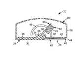
- FIG. 1is a cross-sectional view of an applicator device 20 having a housing 22 that includes a base 24 and an upper cover structure 26 .
- the base 24is generally rectangular in shape, and has a recess 28 located on a bottom face 30 thereof.
- a generally circular opening 32is defined in the recess 28 of the base 24 .
- a raised portion 34is formed on an upper face 36 of the base 24 for holding a patch accelerating or patch applicator assembly 38 .
- a mounting structure or retaining portion of the applicator device 20is formed by a pair of retainers 40 , also referred to as a first retainer and a second retainer, connected to the base 24 (only one retainer 40 is visible in FIG. 1 ).
- the retainer members 40are generally elongate and each have a substantially flat upper surface 42 that is generally parallel to and facing a bottom portion 44 of the recess 28 , and is spaced from the bottom face 30 (i.e., the skin-contacting face) of the base 24 .
- the pair of retainer members 40are located on opposite sides of the opening 32 and are connected to the base 24 at one side of the recess 28 .
- the retainer members 40define an opening 46 at one end for accepting patches between the retainer members 40 and the bottom portion 44 of the recess 28 .
- the upper surfaces 42 of the retainer members 40may be non-stick or release surfaces.
- a non-stick or release surfacecan be achieved, for example, by a non-stick or release coating applied to the upper surfaces 42 .
- the non-stick or release coatingcan be selected according to the desired use of the applicator device 20 .
- a release coatingsuch as a low surface energy silicone, fluoropolymer, or fluoro-silicone release coating, can be selected based upon the adhesives used with patches applied using the patch application device 20 .
- a blade or other cutting meanscan be provided as part of the mounting structure, for separating portions of items from patches mounted on the applicator.
- the upper cover structure 26is connected to the base 24 at or near a perimeter of the base 24 .
- the upper cover structure 26is shaped to fit on the base 24 , and defines a volume, which is selected to provide space for the patch accelerating assembly 38 .
- the housing 22may also provide space for storing patches (e.g., a roll of patches) for eventual deployment by the applicator device 20 .
- a slot 48is defined in a side portion of the upper cover structure 26 . In the embodiment shown in FIG. 1 , the slot 48 is arcuate in shape and generally resembles a half circle, with the open portion of the half circle facing the base 24 of the housing 22 .
- Both the base 24 and the upper cover structure 26can be formed of a polymer material.
- FIG. 2is a perspective view of a portion of the applicator device 20 with the upper cover portion 26 omitted to show interior portions of the device 20 .
- the patch acceleration assembly 38includes a frame member 60 , an impactor 62 , a handle 64 , a bracket 66 , and a torsion spring 68 .
- the torsion spring 68serves as a drive member to bias the impactor relative to the housing.
- the bracket 66is mounted to the raised portion 34 of the base 24 of the housing 22 and pivotally retains the frame member 60 . In some instances the bracket 66 may be directly affixed to the base 24 , for example, if the base has sufficient thickness to allow for placement of the torsion spring 68 .
- the frame member 60can be a wire formed as a rectangular loop.
- the impactor 62is attached to the frame member 60 opposite the bracket 66 , and is the portion of the patch acceleration assembly 38 that interfaces with a patch to move it (i.e., to accelerate it), that is, it is the patch contacting portion of the device.
- the impactor 62has a patch contacting surface 70 that is configured according to characteristics of a desired application, for instance, based upon the shape of a patch to be applied. In the embodiment shown in FIG. 1 , the patch contacting surface 70 is configured so that it is generally parallel to and aligned with the frame member 60 . Furthermore, it will be generally aligned with the bottom face 30 of the device 20 when fully deployed.
- the patch contacting surface 70may be configured so that it is at another angle with respect to the frame member 60 , and with respect to the bottom face 30 of the device 20 when fully deployed. Other such angles are shown in FIGS. 5A , B depicting a portion of devices having alternative patch contacting surfaces. In one embodiment, it may be desirable for the patch contacting surface 70 to be aligned so as to form an angle of between 4 and 15 degrees with the plane of the frame member. In one aspect, the angle of the patch contacting surface 70 may be selected so that it is aligned with the back of the a patch resting on retaining members 40 when the patch contacting surface 70 contacts the patch.
- the impactor 62can be formed of a polymer material.
- the handle 64extends from the impactor 62 , and can be integrally formed with the impactor 62 .
- the handle 64is arranged to protrude through the slot 48 in the upper cover structure 26 of the housing 22 , allowing the impactor 62 position to be manipulated from outside the housing 22 .
- FIG. 1simply represents one configuration for manipulating the patch acceleration assembly 38 .
- a slotmay be provided on the upper cover portion 26 , thereby allowing the handle 64 or any other suitable actuation protrusion to protrude through the upper cover portion 26 .
- the method for manipulating the patch acceleration assembly 38need not be by means of a direct mechanical connection.
- various linkages or gearsmay be provided such that a button or knob on the exterior of the housing 22 may be pressed or turned to manipulate the patch acceleration assembly 38 .
- the patch acceleration assembly 38may be moved by a motor or solenoid that is electrically controlled by a button or knob on the exterior of the housing 22 .
- the torsion spring 68biases the frame 60 of the patch acceleration assembly 38 relative to the base 24 of the housing 22 .
- the torsion spring 68can be a conventional coiled spring steel torsion spring.
- the torsion spring 68biases the frame 60 , and therefore also the impactor 62 , toward the opening 32 in the base 24 of the housing 22 .
- the impactorIn a substantially de-energized state, the impactor is at rest and positioned near the opening 32 in the base 24 of the housing 22 .
- an operatorcan store potential energy in the torsion spring 68 .
- Energy stored in the torsion spring 68can be used to accelerate the impactor 62 toward a patch and also to accelerate a patch that has contacted the impactor 62 .
- the amount of energy stored in the torsion spring 68will vary depending on the amount of displacement of the impactor 62 away from the opening 32 and along the arcuate path.
- the appropriate torsion spring constantwill depend upon a number of parameters, including the mass of the patch acceleration assembly, the mass of the patch, the arc length through which the patch acceleration assembly travels, and the desired speed of the patch on impact with a surface.
- the torsion spring constantwill often be more than about 0.5 Newton*mm/degree and sometimes more than about 2.0 Newton*mm/degree.
- the torsion spring constantwill often be less than about 5.0 Newton*mm/degree and sometimes less than about 4.0 Newton*mm/degree.
- the impactor 62can be held at various points along the arcuate path either manually or, in some embodiments, with holding means (not shown) that engage and temporarily secure the handle 64 along the slot 48 in the upper cover structure 26 of the housing 22 .
- demarcations or other indicatorse.g., a force readout display
- the range of angular travel of the patch acceleration assemblywill often be less than about 170 degrees and sometimes less than about 110 degrees.
- the range of angular travel of the patch acceleration assemblywill often be more than about 10 degrees and sometimes more than about 60 degrees.
- the mass of the patch acceleration assemblywill often be more than about 1 gram and sometimes more than about 5 grams.
- the mass of the patch acceleration assemblywill often be less than about 100 grams and sometimes less than about 30 grams.
- FIG. 3is a perspective view of a patch 72 (e.g., a patch 72 carrying a microneedle array 74 ) mounted on the applicator device 20 .
- the patch 72is disposed between the retainer members 40 and the bottom portion 44 of the recess 28 in the base 24 of the housing 22 .
- the microneedle array 74faces away from the opening 32 in the base 24 of the housing 22 .
- the patch 72which may have adhesive surrounding the microneedle array 74 on the surface facing away from the patch application device 20 , contacts the upper surfaces 42 of the retainer members 40 , but is generally not adhered firmly to the retainer members 40 due to the release character of the upper surfaces 42 .
- microneedle array carried on the patch 72is generally aligned relative to the opening 32 in the base 24 of the housing 22 (the opening 32 is not visible in FIG. 3 ).
- the retainer members 40have cutaway portions 76 that provide an enlarged, partially circular open region that is generally aligned with the opening 32 on the bottom portion 44 of the recess 28 of the base 24 of the housing 22 .
- the wider, open region defined by the cutaway portions 76facilitates patch application by reducing the amount of deflection of the patch 72 required during deployment to move the patch 72 from a mounted position on the applicator device 20 to a target location.
- Such cutaway portions 76are optional and may be unnecessary if, for example, the patch has a generally rectangular shape.
- FIG. 4is a partial cross-sectional view of a microneedle array cartridge 80 , having a patch 72 and a cover 82 , mounted on the applicator device 20 .
- Mounting the patch 72 on the applicator device 20includes the following steps.
- the cartridge 80is partially slid onto the retainer members 40 .
- the cartridge 80is slid further along the retainer members 40 , simultaneously separating the cover 82 from the patch 72 , until the patch 72 is fully mounted on the applicator device 20 (e.g., such that the microneedle array 74 is aligned with the opening 32 defined in the bottom portion 44 of the recess 28 ).
- the cover 82is removed from (i.e., separated from) the patch 72 to uncover and expose the microneedle array 74 prior to microneedle deployment.
- the patch mounting structure shown in FIGS. 3 and 4is provided by way of example, and not limitation.
- other means of mounting a patch on the applicator device 20can be used, and the design of the mounting structure is generally independent of the design of other components of the applicator device 20 .
- one or more patchescan be stored inside the housing 22 prior to application, and then dispensed for application to a target site.
- the microneedle array 74 of the patch 72can be deployed as follows. An operator “loads” or “energizes” the patch accelerating assembly 38 using the handle 64 , to store potential energy in the torsion spring 68 , by moving the impactor 62 and frame 60 along the arcuate path.
- the operatorcan “load” the patch accelerating assembly 38 either before or after the patch 72 is mounted to the device 20 .
- the amount of energy stored in the torsion spring 68can be selected based on characteristics of the desired patch application site, and may vary for different target sites, or may vary for different patches. Storing different amounts of energy in the torsion spring 68 permits adjustment of an acceleration rate of a patch moved by the patch accelerating assembly 38 .
- the applicator device 20is also positioned against an application surface, and the opening 32 is positioned relative to a target site for patch delivery. Suitable sites for microneedle patch application on a patient's skin will vary, and the operator must select a suitable position and orientation of the applicator device 20 .
- the patch accelerating assembly 38is energized, the patch 72 is fully mounted to the applicator device 20 , and the device 20 is positioned relative to the target location, the operator then actuates the impactor 62 by releasing the energy stored in the torsion spring 68 , which moves the impactor 62 toward the patch 72 along an arcuate path, which can correspond to the arcuate path defined by the slot 48 in the housing 22 .
- the patch contacting surface 70 of the impactor 62then contacts the patch 72 to transfer energy to the patch 72 and accelerate it toward the target site.
- Release of the stored energymay be by any suitable means, such as by pressing a button or turning a knob to release a latch or other locking mechanism and thereby allowing the patch accelerating assembly 38 to accelerate the patch 72 toward the target site.
- the arcuate path defined by the slot 48is a portion (or arc) of a circle. It should be understood that in other embodiments the impactor may move along any type of arcuate (i.e., curved) path. Furthermore the path may be substantially arcuate, that is, although predominately curved, there may be small portions of the path which are not curved.
- the patchmay be directly affixed or otherwise releasably held by the patch acceleration assembly.
- the patchmay be releasably held to the impactor through magnetic attraction.
- the impactormay comprise a magnet and the patch may comprise a metal capable of magnetic attraction.
- the impactorfor example, may be a permanent magnet or an electromagnet and the patch backing may comprise a metal that can be magnetically attracted.
- a thin layer of ferrous foilmay be incorporated into the patch backing. Such a magnetic attraction can allow the patch to be held to the impactor until the patch contacts the skin.
- the adhesion between the patch and the skincan then be sufficient to allow the patch acceleration assembly, and thus the applicator, to be removed from the patch while allowing the patch to remain in place on the skin.
- the adhesive force between the patch and the skinis typically more than the magnetic, attractive force between the patch and the impactor. In some instances the adhesive force between patch and skin may be more than about twice as much as the magnetic, attractive force between patch and impactor. The appropriate amount of magnetic interaction may be readily determined, and will depend on a number of factors, including the magnitude of the adhesive force between the patch and the skin, the design of the applicator and its method of removal from the patch once the patch is applied to the skin.
- the patchmay incorporate a magnet and the impactor can be made of a magnetic material, such as a steel leaf spring.
- Releasable magnetic attachmentmay be used with any of the hereinbefore or hereinafter describe embodiments, as well as with other embodiments of applicators, such as those described in United States Patent Application Publication 2002-0087182 and International Patent Publication WO 05/123173, the disclosures of which are herein incorporated by reference.
- the patchmay be releasably attached to a portion of the holding mechanism.
- the impactormay be an elongated drive member, such as a leaf spring having an opening or hole in its movable end.
- the patchmay have a stub or other protrusion extending from its back surface that can be placed through the opening or hole in the leaf spring and gripped by the holding mechanism. The leaf spring will then also be held in place in a cocked position, as it will be pinned between the patch and the holding mechanism.
- a single use, disposable unitmay be provided with the patch accelerating assembly 38 already in an energized position, so that the device may be positioned and fired with the press of a button.
- the patch 72can be moved toward the target site along an at least partially arcuate path, such as when the patch 72 is moved in contact with the impactor 62 as the impactor 62 moves along its arcuate path.
- the patch 72could also move linearly toward the target site after contacting the impactor 62 , such as where the impactor 62 momentarily contacts the patch 72 and transfers its kinetic energy to the patch 72 (which then travels along a generally linear path that differs from the arcuate path of the impactor 62 ).
- the deployed patch 72can be adhered to the target site, as desired for delivery of molecules.
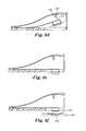
- FIG. 6Ais a perspective view of another embodiment of an applicator device 120 having a housing 122 that includes a base 124 and an upper cover structure 126 .
- the deviceis elongate in shape and has a first, tapered end 127 and a second end 129 .
- the second end 129has a top and bottom sealed by a top peelable seal 131 having a tab 133 and a bottom peelable seal 132 having a tab 135 (only tab 135 is visible in FIG. 6A ).
- FIG. 6Bshows the applicator device after the peelable seals 131 , 132 have been removed.
- a trigger 137is integrally formed in the top surface of the housing 122 .
- the triggeris connected to the top surface of the housing at a single attachment point 139 , thus allowing the trigger to be deflected downward by thumb or finger pressure as shown in FIG. 6D .
- FIG. 6Cis a cross-sectional view of the device showing a patch 172 mounted on an impactor 170 .
- the impactor 170is integrally formed with a drive member 166 having a length extending from a fixed end 167 attached to the housing 122 to a movable end 169 .
- the drive member 166is bendable along its length.
- a holding mechanism in the form of a latchuses a hook 125 attached to the housing 122 .
- the hook 125engages with a slot 171 in the movable end 169 of the drive member 166 to hold the movable end 169 of the drive member 166 away from the skin-contacting face 124 of the housing 122 .
- the drive membermay be any elongate, bendable member, such as, for example, a leaf spring.
- a target surfacesuch as a skin surface (not shown).
- Depression of the trigger 137causes the hook 125 to pivot, thus releasing the movable end 169 of the drive member 166 and allowing the drive member 166 to bias the patch 172 towards the skin-contacting face 124 .
- FIG. 6Eshows the drive member 166 fully deployed, having propelled the patch 172 past the skin-contacting face 124 so that the patch is pressed against the skin surface (not shown).
- FIG. 6Fshows the device 120 being removed from the skin surface 181 , leaving a patch 172 with a microneedle array 174 in place on the skin surface 181 .
- the impactor 170is shown as a curled end of a leaf spring, as this allows for a convenient means for providing a holding mechanism (via the slot 171 in the movable end 169 of the leaf spring) while also providing a separate patch contacting and holding surface.
- any variety of suitable shapesmay be used for the movable end 169 of the drive member 166 , including a flat leaf spring having no curled end.
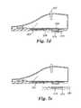
- FIG. 7Ais a perspective top view of another embodiment of an applicator device 220 having a housing 222 that includes a base 224 and an upper cover structure 226 .
- a trigger 237extends from the upper cover structure 226 .
- FIG. 7Bis perspective bottom view of the applicator 220 showing a handle 249 and having retainers 240 for holding a microneedle patch 272 with a microneedle array 274 , similar to the patch retaining structure shown in FIG. 3 .
- FIG. 7Cis a cross-sectional view showing an impactor 270 integrally formed with a drive member 266 having a length extending from a fixed end 267 attached to the housing 222 to a movable end 269 . The drive member 266 is bendable along its length.
- a holding mechanism in the form of a latchuses a hook 225 attached to the housing 222 .
- the hook 225engages with a slot 271 in the movable end 269 of the drive member 266 to hold the movable end 269 of the drive member 266 away from the skin-contacting face 224 of the housing 222 .
- a lifting mechanism 251is shown in a raised position.
- the lifting mechanism 251is operably connected to the handle 249 (shown in dashed lines on the back side of the applicator) and is also configured so that it can lift the drive member 266 into a position such as shown in FIG. 7C , where the drive member 266 has been raised and latched onto hook 225 . In use the device as shown in FIG.
- FIG. 7Cis placed against a target surface, such as a skin surface (not shown).
- the handle 249may be released, thereby releasing the lifting mechanism 251 to a lowered position, such as shown in FIG. 7D .
- the trigger 237may be pushed sideways, as shown in FIG. 7D , thus releasing the movable end 269 of the drive member 266 and allowing the drive member 266 to bias the impactor 270 towards the patch 272 and the skin-contacting face 224 .
- the impactor 270drives the patch 272 from the retainers 240 and past the skin-contacting face 224 so that the patch is pressed against the skin surface (not shown).
- FIG. 7Eshows the device 220 being removed from the skin surface 281 , leaving a patch 272 with a microneedle array 274 in place on the skin surface 281 .
- the applicator 220may be used for applying multiple patches in the following manner. After application of a patch, the handle 249 may be lifted, thereby raising the lifting mechanism 251 and thus the drive member 266 to a raised position, such as shown in FIG. 7C , and the trigger 237 may be pushed back into place to lock the drive member 266 in a raised position.
- the trigger 237may be manually moved into position to lock the drive member 266 .
- the trigger 237may be moved into position to lock the drive member 266 by a spring (not shown) that biases it towards the locked position or by a mechanism (not shown) connected to the handle 249 which causes the trigger 237 to move to the locked position as the drive member 266 is raised by the handle. Any other suitable triggers and re-cocking mechanisms may be employed.
- Another patchmay then be loaded into the retaining mechanism and applied as described above.
- the applicator device of the present inventionmay provide numerous benefits and advantages.
- the housingmay be shaped in a way that generally resembles a mouse for a personal computer. This shape is less threatening to patients than applicators or other drug delivery devices that are shaped, for example, like a gun.
- the housingalso provides adequate interior volume for protecting the patch accelerating assembly and can optionally provide storage space for patches prior to application. Patch mounting may be quickly and easily accomplished, which is helpful for mass inoculations and other applications. It should be understood, however, that any suitable housing shape may be used.
- the housingmay have a circular, square, or rectangular cross-section in some embodiments and may be a polyhedron in certain embodiments (i.e., the housing may define a volume formed by plane faces).
- the housingmay be a polyhedron having one or more rectangular faces, that is, a rectangular polyhedron.
- the housingmay have a flat or planar base with sides that are continuously curved. It is preferred, but not necessary, that the patch accelerating assembly is fully contained (with the exception of the handle) within the housing.
- a torsion spring or leaf springallows for simple and efficient adjustment of force used to apply patch with the applicator device, permitting the applicator device to be used in a variety of contexts and for patch application to a variety of desired patch sites.
- a method of applying a microneedle array using an application device of the present inventioncomprises mounting the microneedle array on the microneedle array application device and moving the microneedle array toward the target site along a substantially arcuate path.
- the arrayfor example, may be affixed to an impactor within the device, as described above. Release of the impactor allows the array to travel towards the target site along a substantially arcuate path.
- a method of applying a microneedle array using an application device of the present inventioncomprises mounting the microneedle array on the microneedle array application device and moving the impactor along a substantially arcuate path to bring the microneedle array into contact with the target site.
- the arraymay be mounted within the application device using a retainer separate from the impactor, such as shown in FIG. 3 , and the impactor may be placed in a loaded position (i.e., where it contains stored energy) and then released so as to travel along an arcuate path. The impactor will then contact the microneedle array (or a patch holding the microneedle array) and bring the microneedle array into contact with the target site.
- a method of applying a microneedle array using an application device of the present inventioncomprises placing a microneedle patch on or adjacent to a target site.
- An application device of the present inventionmay be brought into alignment with the microneedle array and triggered so as to cause the impactor to press the microneedle array into the target site.
- the microneedle patchmay be held in place on a skin surface prior to contacting it with the application device by any suitable means, such as with use of a collapsible patch as described in U.S. Patent Application Ser. No. 60/693,901, filed on Jun. 24, 2005, the disclosure of which is herein incorporated by reference.
- a method of applying a microneedle array using an application device of the present inventioninvolves having the microneedle array reach a desired velocity that is effective to pierce the microneedles into the skin.
- the desired velocityis preferably controlled to limit or prevent stimulation of the underlying nerve tissue.
- the maximum velocity achieved by the microneedle array upon impact with the skinis often 20 meters per second (m/s) or less, potentially 15 m/s or less, and possibly 10 m/s or less. In some instances, the maximum velocity is 8 m/s or less. In other instances, the minimum velocity achieved by the microneedle array upon impact with the skin is often 2 m/s or more, potentially 4 m/s or more, and possibly 6 m/s or more.
- the mass of the portion of the device driving the microneedle array into the skinis preferably light enough to avoid causing undue discomfort to a patient.
- the mass of the impactoris less than about 6 grams, potentially less than about 4 grams, and possibly less than about 2 grams.
- the mass of the impactoris typically more than about 0.4 grams, potentially more than about 0.8 grams, and possibly greater than about 1.2 gram.
- the impactorwill generally be considered to include the portion above and behind the microneedle array, but not to include the portion of the drive member extending away from the movable end of the drive member and towards the fixed end of the drive member.
- the velocity achieved by the microneedle array upon impact with the skinwill be between about 4 m/s and 8 m/s, and the mass of the impactor will be between about 0.4 grams and about 2 grams.
- Use of a leaf spring as a drive member directly coupled to a microneedle patchmay be particularly advantageous, as this allows the device to obtain desired velocities upon impact with the skin in combination with a relatively low mass impactor.
- Such high-speed, low-mass deliverymay be particularly advantageous when applying a microneedle array having a large number of microneedles. While not wishing to be bound by theory, it is believed that the momentum of an array having a large number of microneedles can be quite low and still achieve acceptable penetration of the microneedles through the stratum corneum, because each microneedle has a very tiny mass and only penetrates a relatively short distance into the skin. In particular, insertion of microneedle arrays having more than 100 microneedles, often more than 500 microneedles, and occasionally more than 1000 microneedles may be particularly effective when performed using devices as described above.
- the depth of penetration of the microneedleswill vary depending on a number of factors, such as the size and design of both the microneedles and the microneedle array, as well as upon the velocity with which the array impacts the skin.
- the microneedleswill penetrate to a depth of more than 40 ⁇ m, sometimes more than 80 ⁇ m, and occasionally more than 100 ⁇ m.
- the microneedleswill penetrate to a depth of less than 300 ⁇ m, sometimes less than 200 ⁇ m, and occasionally less than 150 ⁇ m.
- the microneedleswill penetrate to a depth that is more than 20% of the full height of the microneedle, sometimes more than 40%, and occasionally more than 50%.
- the microneedleswill penetrate to a depth that is less than about 80% of the full height of the microneedle, sometimes less than 60%, and occasionally less than 50%.
- the microneedlesare typically less than 500 microns in height, and sometimes less than 300 microns in height.
- the microneedlesare typically more than 20 microns in height, often more than 50 microns in height, and sometimes more than microns in height.
- the height of the microneedlesmay be measured as the distance that they protrude from a flat base or substrate.
- the microneedlesmay protrude from an irregular substrate, for example, each microneedle may rest upon a flat base or pedestal that itself protrudes from a planar substrate.
- the application devicebe designed such that the microneedle array travels at a velocity at or above the desired minimum velocities over a distance that is sufficient to accommodate the variations in skin location and appendage size relative to the application device.
- the microneedle array in the application devicemay move at or above the minimum velocity over a distance of one millimeter or more. In some embodiments, the microneedle array may move at or above the minimum velocity over a distance of 5 millimeters or more.
- microneedle arrays useful in the various embodiments of the inventionmay comprise any of a variety of configurations, such as those described in the following patents and patent applications, the disclosures of which are herein incorporated by reference.
- One embodiment for the microneedle arrayscomprises the structures disclosed in United States Patent Application Publication No. 2003/0045837.
- the disclosed microstructures in the aforementioned patent applicationare in the form of microneedles having tapered structures that include at least one channel formed in the outside surface of each microneedle.
- the microneedlesmay have bases that are elongated in one direction.
- the channels in microneedles with elongated basesmay extend from one of the ends of the elongated bases towards the tips of the microneedles.
- the channels formed along the sides of the microneedlesmay optionally be terminated short of the tips of the microneedles.
- the microneedle arraysmay also include conduit structures formed on the surface of the substrate on which the microneedle array is located. The channels in the microneedles may be in fluid communication with the conduit structures.
- Another embodiment for the microneedle arrayscomprises the structures disclosed U.S. Patent Application Publication No. 2005/0261631, which describes microneedles having a truncated tapered shape and a controlled aspect ratio.
- Still another embodiment for the microneedle arrayscomprises the structures disclosed in U.S. Pat. No. 6,091,975 (Daddona, et al.) which describes blade-like microprotrusions for piercing the skin.
- Still another embodiment for the microneedle devicescomprises the structures disclosed in U.S. Pat. No. 6,312,212 (Sherman, et al.) which describes tapered structures having a hollow central channel. Still another embodiment for the micro arrays comprises the structures disclosed in U.S. Pat. No. 6,379,324 (Gartstein, et al.) which describes hollow microneedles having at least one longitudinal blade at the top surface of tip of the microneedle.
- Microneedle arrays and microneedle patches of the present inventionmay be used to deliver drugs (including any pharmacological agent or agents) through the skin in a variation on transdermal delivery, or to the skin for intradermal or topical treatment, such as vaccination.
- drugs that are of a large molecular weightmay be delivered transdermally. Increasing molecular weight of a drug typically causes a decrease in unassisted transdermal delivery.
- Microneedle arrays of the present inventionhave utility for the delivery of large molecules that are ordinarily difficult to deliver by passive transdermal delivery. Examples of such large molecules include proteins, peptides, nucleotide sequences, monoclonal antibodies, DNA vaccines, polysaccharides, such as heparin, and antibiotics, such as ceftriaxone.
- microneedle arrays and microneedle patches of the present inventionmay have utility for enhancing or allowing transdermal delivery of small molecules that are otherwise difficult or impossible to deliver by passive transdermal delivery.
- moleculesinclude salt forms; ionic molecules, such as bisphosphonates, preferably sodium alendronate or pamedronate; and molecules with physicochemical properties that are not conducive to passive transdermal delivery.
- microneedle arrays and microneedle patches of the present inventionmay have utility for enhancing delivery of molecules to the skin, such as in dermatological treatments, vaccine delivery, or in enhancing immune response of vaccine adjuvants.
- Microneedle arrays and microneedle patchesmay be used for immediate delivery, that is where they are applied and immediately removed from the application site, or they may be left in place for an extended time, which may range from a few minutes to as long as 1 week.
- an extended time of deliverymay be from 1 to 30 minutes to allow for more complete delivery of a drug than can be obtained upon application and immediate removal.
- an extended time of deliverymay be from 4 hours to 1 week to provide for a sustained release of drug.
Landscapes
- Health & Medical Sciences (AREA)
- Engineering & Computer Science (AREA)
- Life Sciences & Earth Sciences (AREA)
- Veterinary Medicine (AREA)
- Animal Behavior & Ethology (AREA)
- Biomedical Technology (AREA)
- Heart & Thoracic Surgery (AREA)
- Public Health (AREA)
- General Health & Medical Sciences (AREA)
- Medical Informatics (AREA)
- Surgery (AREA)
- Anesthesiology (AREA)
- Hematology (AREA)
- Dermatology (AREA)
- Molecular Biology (AREA)
- Nuclear Medicine, Radiotherapy & Molecular Imaging (AREA)
- Vascular Medicine (AREA)
- Media Introduction/Drainage Providing Device (AREA)
Abstract
Description
Claims (18)
Priority Applications (1)
| Application Number | Priority Date | Filing Date | Title |
|---|---|---|---|
| US11/993,137US8784363B2 (en) | 2005-06-27 | 2006-06-23 | Microneedle array applicator device and method of array application |
Applications Claiming Priority (4)
| Application Number | Priority Date | Filing Date | Title |
|---|---|---|---|
| US69444705P | 2005-06-27 | 2005-06-27 | |
| US74629806P | 2006-05-03 | 2006-05-03 | |
| US11/993,137US8784363B2 (en) | 2005-06-27 | 2006-06-23 | Microneedle array applicator device and method of array application |
| PCT/US2006/024671WO2007002521A2 (en) | 2005-06-27 | 2006-06-23 | Microneedle array applicator device |
Related Parent Applications (1)
| Application Number | Title | Priority Date | Filing Date |
|---|---|---|---|
| PCT/US2006/024671A-371-Of-InternationalWO2007002521A2 (en) | 2005-06-27 | 2006-06-23 | Microneedle array applicator device |
Related Child Applications (1)
| Application Number | Title | Priority Date | Filing Date |
|---|---|---|---|
| US14/333,676DivisionUS9789249B2 (en) | 2005-06-27 | 2014-07-17 | Microneedle array applicator device and method of array application |
Publications (2)
| Publication Number | Publication Date |
|---|---|
| US20100222743A1 US20100222743A1 (en) | 2010-09-02 |
| US8784363B2true US8784363B2 (en) | 2014-07-22 |
Family
ID=37054466
Family Applications (2)
| Application Number | Title | Priority Date | Filing Date |
|---|---|---|---|
| US11/993,137Active2029-03-23US8784363B2 (en) | 2005-06-27 | 2006-06-23 | Microneedle array applicator device and method of array application |
| US14/333,676Expired - Fee RelatedUS9789249B2 (en) | 2005-06-27 | 2014-07-17 | Microneedle array applicator device and method of array application |
Family Applications After (1)
| Application Number | Title | Priority Date | Filing Date |
|---|---|---|---|
| US14/333,676Expired - Fee RelatedUS9789249B2 (en) | 2005-06-27 | 2014-07-17 | Microneedle array applicator device and method of array application |
Country Status (7)
| Country | Link |
|---|---|
| US (2) | US8784363B2 (en) |
| EP (2) | EP1901799B1 (en) |
| JP (1) | JP5144510B2 (en) |
| CN (1) | CN101208130B (en) |
| AU (1) | AU2006261898B2 (en) |
| CA (1) | CA2613111C (en) |
| WO (1) | WO2007002521A2 (en) |
Cited By (14)
| Publication number | Priority date | Publication date | Assignee | Title |
|---|---|---|---|---|
| US11305056B2 (en) | 2017-07-14 | 2022-04-19 | Amgen Inc. | Needle insertion-retraction system having dual torsion spring system |
| US11389632B2 (en) | 2020-12-21 | 2022-07-19 | Mediccene Inc. | Intradermal drug delivery device |
| US11406805B2 (en)* | 2016-08-08 | 2022-08-09 | Avedro, Inc. | Systems and methods for cross-linking treatments of an eye |
| US11877848B2 (en) | 2021-11-08 | 2024-01-23 | Satio, Inc. | Dermal patch for collecting a physiological sample |
| US11964121B2 (en) | 2021-10-13 | 2024-04-23 | Satio, Inc. | Mono dose dermal patch for pharmaceutical delivery |
| US12023156B2 (en) | 2021-10-13 | 2024-07-02 | Satio, Inc. | Dermal patch for collecting a physiological sample |
| US12029562B2 (en) | 2021-04-14 | 2024-07-09 | Satio, Inc. | Dermal patch system |
| US12048543B2 (en) | 2021-11-08 | 2024-07-30 | Satio, Inc. | Dermal patch for collecting a physiological sample with removable vial |
| US12053284B2 (en) | 2021-11-08 | 2024-08-06 | Satio, Inc. | Dermal patch for collecting a physiological sample |
| WO2024238798A1 (en)* | 2023-05-16 | 2024-11-21 | Biolinq Incorporated | Wearable analyte monitoring device with replaceable microneedle array unit |
| US12178979B2 (en) | 2021-10-13 | 2024-12-31 | Satio, Inc. | Dermal patch for delivering a pharmaceutical |
| USD1057153S1 (en) | 2022-04-29 | 2025-01-07 | Biolinq Incorporated | Microneedle array sensor applicator device |
| US12214346B2 (en) | 2021-10-13 | 2025-02-04 | Satio, Inc. | Dermal patch with a diagnostic test strip |
| US12440133B2 (en) | 2024-03-29 | 2025-10-14 | Satio, Inc. | Dermal patch for collecting a physiological sample |
Families Citing this family (101)
| Publication number | Priority date | Publication date | Assignee | Title |
|---|---|---|---|---|
| GB0402131D0 (en) | 2004-01-30 | 2004-03-03 | Isis Innovation | Delivery method |
| JP2008520369A (en) | 2004-11-18 | 2008-06-19 | スリーエム イノベイティブ プロパティズ カンパニー | Inconspicuous microneedle array applicator |
| EP1871459B1 (en) | 2005-04-07 | 2019-06-19 | 3M Innovative Properties Company | System for tool feedback sensing |
| EP1896115B2 (en) | 2005-06-27 | 2020-01-22 | 3M Innovative Properties Company | Microneedle cartridge assembly |
| US9119945B2 (en) | 2006-04-20 | 2015-09-01 | 3M Innovative Properties Company | Device for applying a microneedle array |
| ES2820335T3 (en) | 2007-04-16 | 2021-04-20 | Corium Inc | Solvent Cast Microneedle Arrays Containing Active Agent |
| GB2448493B (en) | 2007-04-16 | 2009-10-14 | Dewan Fazlul Hoque Chowdhury | Microneedle transdermal delivery device |
| WO2009048607A1 (en) | 2007-10-10 | 2009-04-16 | Corium International, Inc. | Vaccine delivery via microneedle arrays |
| US9220678B2 (en) | 2007-12-24 | 2015-12-29 | The University Of Queensland | Coating method |
| WO2009097660A1 (en) | 2008-02-07 | 2009-08-13 | The University Of Queensland | Patch production |
| AU2009250341A1 (en) | 2008-05-23 | 2009-11-26 | The University Of Queensland | Analyte detection using a needle projection patch |
| RU2494769C2 (en) | 2008-11-18 | 2013-10-10 | 3М Инновейтив Пропертиз Компани | Package of hollow microneedles and method of using it |
| EP2399643A4 (en) | 2009-02-23 | 2012-08-22 | Medrx Co Ltd | Applicator for microneedle array |
| US20100256524A1 (en) | 2009-03-02 | 2010-10-07 | Seventh Sense Biosystems, Inc. | Techniques and devices associated with blood sampling |
| EP3354312A1 (en) | 2009-07-31 | 2018-08-01 | 3M Innovative Properties Co. | Hollow microneedle arrays |
| US20120184916A1 (en)* | 2009-08-07 | 2012-07-19 | Medrx Co., Ltd. | Applicator device of pinholder type microneedle |
| US9750924B2 (en) | 2010-01-22 | 2017-09-05 | Medrx Co., Ltd. | Adhesive patching aid for microneedle adhesive skin patch |
| WO2011094573A1 (en) | 2010-01-28 | 2011-08-04 | Seventh Sense Biosystems, Inc. | Monitoring or feedback systems and methods |
| GB201007207D0 (en)* | 2010-04-29 | 2010-06-16 | Univ Cork | Method |
| US9687640B2 (en) | 2010-05-04 | 2017-06-27 | Corium International, Inc. | Applicators for microneedles |
| WO2011140274A2 (en) | 2010-05-04 | 2011-11-10 | Corium International, Inc. | Method and device for transdermal delivery of parathyroid hormone using a microprojection array |
| WO2011163347A2 (en) | 2010-06-23 | 2011-12-29 | Seventh Sense Biosystems, Inc. | Sampling devices and methods involving relatively little pain |
| JP5562138B2 (en) | 2010-06-24 | 2014-07-30 | シスメックス株式会社 | Micropore forming device |
| WO2012006677A1 (en)* | 2010-07-14 | 2012-01-19 | The University Of Queensland | Patch applying apparatus |
| US20120016308A1 (en) | 2010-07-16 | 2012-01-19 | Seventh Sense Biosystems, Inc. | Low-pressure packaging for fluid devices |
| US20130158482A1 (en) | 2010-07-26 | 2013-06-20 | Seventh Sense Biosystems, Inc. | Rapid delivery and/or receiving of fluids |
| WO2012021801A2 (en) | 2010-08-13 | 2012-02-16 | Seventh Sense Biosystems, Inc. | Systems and techniques for monitoring subjects |
| WO2012048285A1 (en)* | 2010-10-08 | 2012-04-12 | Lanco Biosciences, Inc. | Delivery of bisphosphonates by microinjection systems |
| WO2012064802A1 (en) | 2010-11-09 | 2012-05-18 | Seventh Sense Biosystems, Inc. | Systems and interfaces for blood sampling |
| US8814831B2 (en) | 2010-11-30 | 2014-08-26 | Becton, Dickinson And Company | Ballistic microneedle infusion device |
| US8795234B2 (en) | 2010-11-30 | 2014-08-05 | Becton, Dickinson And Company | Integrated spring-activated ballistic insertion for drug infusion device |
| US9950109B2 (en) | 2010-11-30 | 2018-04-24 | Becton, Dickinson And Company | Slide-activated angled inserter and cantilevered ballistic insertion for intradermal drug infusion |
| WO2012075209A1 (en)* | 2010-12-02 | 2012-06-07 | Lanco Biosciences, Inc. | Delivery of triptans by microinjection systems |
| WO2012075339A1 (en)* | 2010-12-02 | 2012-06-07 | Lanco Biosciences, Inc. | Delivery of heparins by microinjection systems |
| WO2012075375A1 (en)* | 2010-12-02 | 2012-06-07 | Lanco Biosciences, Inc. | Delivery of parathyroid hormones by microinjection systems |
| US20120143119A1 (en)* | 2010-12-02 | 2012-06-07 | Lanco Biosciences, Inc. | Delivery of Serotonin Receptor Antagonists By Microinjection Systems |
| AU2011349277A1 (en) | 2010-12-22 | 2013-06-27 | Valeritas, Inc. | Microneedle patch applicator |
| IT1403293B1 (en) | 2010-12-27 | 2013-10-17 | Fond Don Carlo Gnocchi Onlus | NEEDLE APPLIANCE FOR TRANSDERMIC DRUG ADMINISTRATION. |
| CN102727992A (en)* | 2011-03-31 | 2012-10-17 | 株式会社汉比特科技与创新 | Stamp type needle assembly |
| KR102013466B1 (en) | 2011-04-29 | 2019-08-22 | 세븐쓰 센스 바이오시스템즈, 인크. | Delivering and/or receiving fluids |
| CN103874461B (en) | 2011-04-29 | 2017-05-10 | 第七感生物系统有限公司 | Devices for collecting and/or manipulating blood spots or other bodily fluids |
| WO2012149155A1 (en) | 2011-04-29 | 2012-11-01 | Seventh Sense Biosystems, Inc. | Systems and methods for collecting fluid from a subject |
| US20130158468A1 (en) | 2011-12-19 | 2013-06-20 | Seventh Sense Biosystems, Inc. | Delivering and/or receiving material with respect to a subject surface |
| CN103764197B (en)* | 2011-09-07 | 2017-03-15 | 3M创新有限公司 | Delivery system for hollow microneedle arrays |
| WO2013038890A1 (en)* | 2011-09-16 | 2013-03-21 | 久光製薬株式会社 | Applicator |
| NL2007461C2 (en) | 2011-09-23 | 2013-03-26 | Ambro B V | System for transporting fluid across or into a biological barrier, device and capsule as part of the system. |
| CA2851606C (en)* | 2011-10-12 | 2020-08-04 | 3M Innovative Properties Company | Integrated microneedle array delivery system |
| EP2765927B1 (en) | 2011-10-12 | 2021-02-24 | Vaxxas Pty Limited | Delivery device |
| US20140236090A1 (en)* | 2011-10-12 | 2014-08-21 | 3M Innovative Properties Company | Integrated microneedle array delivery system |
| USD692997S1 (en) | 2011-11-08 | 2013-11-05 | Becton Dickinson France, S.A.S. | Microinfuser |
| USD693455S1 (en) | 2011-11-08 | 2013-11-12 | Becton, Dickinson And Company | Microinfuser |
| USD692552S1 (en) | 2011-11-08 | 2013-10-29 | Becton Dickinson France, S.A.S. | Microinfuser |
| BR112015014969B1 (en) | 2012-12-21 | 2021-12-07 | Corium, Inc | MICROSTRUCTURE APPARATUS AND METHOD OF MANUFACTURING A MICROSTRUCTURE APPARATUS |
| CN104870049B (en)* | 2012-12-21 | 2018-06-08 | 3M创新有限公司 | Adhesive assembly and the micropin injection device including the adhesive assembly |
| CN104955517B (en)* | 2012-12-21 | 2017-09-26 | 久光制药株式会社 | Applicator |
| CN104884119B (en) | 2012-12-27 | 2018-04-20 | 3M创新有限公司 | Product with hollow microneedles and preparation method thereof |
| KR102244475B1 (en) | 2013-01-08 | 2021-04-23 | 쓰리엠 이노베이티브 프로퍼티즈 컴파니 | Applicator for applying a microneedle device to skin |
| EP2968887B1 (en) | 2013-03-12 | 2022-05-04 | Corium, Inc. | Microprojection applicators |
| CA2903763C (en) | 2013-03-15 | 2021-11-16 | Corium International, Inc. | Microarray with polymer-free microstructures, methods of making, and methods of use |
| AU2014233541B2 (en) | 2013-03-15 | 2018-11-22 | Corium Pharma Solutions, Inc. | Microarray for delivery of therapeutic agent, methods of use, and methods of making |
| BR112015022625B1 (en) | 2013-03-15 | 2023-01-31 | Corium, Inc | MICROSTRUCTURE DEVICE FOR DELIVERY OF THERAPEUTIC AGENT |
| ES2939317T3 (en) | 2013-03-15 | 2023-04-20 | Corium Pharma Solutions Inc | Multi-impact micro-spray applicators |
| EP3003458B1 (en) | 2013-05-31 | 2019-12-04 | 3M Innovative Properties Company | Microneedle injection apparatus comprising a dual cover |
| KR102274902B1 (en) | 2013-05-31 | 2021-07-07 | 쓰리엠 이노베이티브 프로퍼티즈 컴파니 | Microneedle injection and infusion apparatus and method of using same |
| EP3381500B1 (en) | 2013-05-31 | 2020-11-04 | 3M Innovative Properties Co. | Microneedle injection apparatus comprising an inverted actuator |
| US20150038897A1 (en) | 2013-07-30 | 2015-02-05 | Zosano Pharma, Inc. | Low-Profile Microneedle Patch Applicator |
| CN105658267B (en)* | 2013-09-05 | 2019-10-25 | 赛诺菲-安万特德国有限公司 | Driving mechanism for needle insertion assembly |
| JP6215343B2 (en) | 2013-11-05 | 2017-10-18 | 久光製薬株式会社 | applicator |
| JP6199702B2 (en)* | 2013-11-06 | 2017-09-20 | 久光製薬株式会社 | applicator |
| CA2945351C (en) | 2014-04-30 | 2017-09-05 | Kimberly-Clark Worldwide, Inc. | Controller portion of transdermal drug delivery apparatus and methods |
| US10624843B2 (en) | 2014-09-04 | 2020-04-21 | Corium, Inc. | Microstructure array, methods of making, and methods of use |
| US10292734B1 (en) | 2014-10-24 | 2019-05-21 | Verily Life Sciences Llc | Micro-structures with magnetic removal capability and optionally clear optical path |
| EP3251721B1 (en)* | 2015-01-27 | 2019-12-18 | Toppan Printing Co., Ltd. | Transdermal administration device |
| US11147954B2 (en) | 2015-02-02 | 2021-10-19 | Vaxxas Pty Limited | Microprojection array applicator and method |
| WO2017004067A1 (en) | 2015-06-29 | 2017-01-05 | Corium International, Inc. | Microarray for delivery of therapeutic agent, methods of use, and methods of making |
| USD767120S1 (en) | 2015-07-30 | 2016-09-20 | Becton, Dickinson And Company | Medical injector |
| USD776262S1 (en) | 2015-07-30 | 2017-01-10 | Becton, Dickinson And Company | Medical injector |
| USD776263S1 (en) | 2015-07-30 | 2017-01-10 | Becton, Dickinson And Company | Medical injector |
| USD794776S1 (en) | 2015-07-30 | 2017-08-15 | Becton, Dickinson And Company | Medical injector |
| USD774640S1 (en) | 2015-07-30 | 2016-12-20 | Becton, Dickinson And Company | Medical injector |
| USD776265S1 (en) | 2015-07-30 | 2017-01-10 | Becton, Dickinson And Company | Medical injector |
| USD776264S1 (en) | 2015-07-30 | 2017-01-10 | Becton, Dickinson And Company | Medical injector |
| EP3345648A4 (en) | 2015-09-02 | 2019-04-17 | Hisamitsu Pharmaceutical Co., Inc. | APPLICATOR |
| WO2017045031A1 (en) | 2015-09-18 | 2017-03-23 | Vaxxas Pty Limited | Microprojection arrays with microprojections having large surface area profiles |
| EP3355981A4 (en) | 2015-09-28 | 2019-05-22 | Vaxxas Pty Limited | MICROAILLY NETWORK HAVING IMPROVED SKIN PENETRATION PROPERTIES AND ASSOCIATED METHODS |
| KR101746048B1 (en)* | 2016-09-13 | 2017-06-12 | 주식회사 라파스 | Microneedle patch applicator |
| WO2018176102A1 (en) | 2017-03-31 | 2018-10-04 | Vaxxas Pty Limited | Device and method for coating surfaces |
| WO2018227246A1 (en) | 2017-06-13 | 2018-12-20 | Vaxxas Pty Limited | Quality control of substrate coatings |
| CA3071680A1 (en) | 2017-08-04 | 2019-02-07 | Vaxxas Pty Limited | Compact high mechanical energy storage and low trigger force actuator for the delivery of microprojection array patches (map) |
| DE102017007485A1 (en)* | 2017-08-09 | 2019-02-14 | Lts Lohmann Therapie-Systeme Ag | Adapter system with frame, active ingredient pad and lid |
| CN111405924B (en)* | 2017-11-30 | 2022-03-04 | 久光制药株式会社 | Applicator, cartridge and application kit |
| US10786203B1 (en)* | 2018-01-30 | 2020-09-29 | Daniel M. Besser | Medical patch applicator device |
| WO2019166572A1 (en) | 2018-02-28 | 2019-09-06 | Pharming Intellectual Property B.V. | Pharmaceutical system for transdermal administration of a c1 -esterase inhibitor |
| US11938178B2 (en)* | 2018-07-09 | 2024-03-26 | Dbv Technologies | Optimized epicutaneous vaccination |
| DE102019001251A1 (en)* | 2019-02-21 | 2020-08-27 | Lts Lohmann Therapie-Systeme Ag | Microneedle plaster applicator |
| CA3163746A1 (en)* | 2019-12-05 | 2021-06-10 | Follica, Inc. | Needling devices and penetration depths |
| US20230191099A1 (en)* | 2020-02-20 | 2023-06-22 | Jubilee Biotech Co., Ltd. | Applicator for drug delivery and microneedle patch used therefor |
| WO2021257624A1 (en) | 2020-06-17 | 2021-12-23 | Biolinq, Inc. | Devices and methods for application of microneedle arrays using radial and axial accelerations |
| SE545876C2 (en) | 2021-09-28 | 2024-02-27 | Biolinq Incorporated | Microneedle enclosure and applicator device for microneedle array based continuous analyte monitoring device |
| CN114081538B (en)* | 2021-11-12 | 2023-09-15 | 江西中医药大学 | Microneedle device for skin tissue fluid puncture |
| USD1033641S1 (en) | 2021-12-17 | 2024-07-02 | Biolinq Incorporated | Microneedle array sensor applicator device |
Citations (94)
| Publication number | Priority date | Publication date | Assignee | Title |
|---|---|---|---|---|
| US3034507A (en) | 1960-05-10 | 1962-05-15 | American Cyanamid Co | Intracutaneous injection device |
| US3072122A (en) | 1959-01-15 | 1963-01-08 | Rosenthal Sol Roy | Package for transcutaneous injection |
| US3123212A (en) | 1964-03-03 | Multiple disposable intracutaneous injector package | ||
| US3136314A (en) | 1960-08-01 | 1964-06-09 | Kravitz Harvey | Vaccinating devices |
| USRE25637E (en) | 1964-09-08 | Means for vaccinating | ||
| US3221740A (en) | 1962-08-31 | 1965-12-07 | Rosenthal Sol Roy | Injection device |
| US3246647A (en) | 1962-07-23 | 1966-04-19 | American Cyanamid Co | Disposable intracutaneous injector |
| US3322121A (en) | 1965-11-26 | 1967-05-30 | Oscar H Banker | Skin-puncturing unit with a collapsible protective cover |
| GB1080986A (en) | 1964-09-02 | 1967-08-31 | Allen And Hanburys Surgical En | Multiple puncture apparatus |
| US3466131A (en) | 1967-09-07 | 1969-09-09 | Becton Dickinson Co | Dispensing applicator package |
| US3510933A (en) | 1967-05-26 | 1970-05-12 | American Cyanamid Co | Apparatus and method for continuously forming intracutaneous injectors |
| US3512520A (en) | 1967-11-01 | 1970-05-19 | Michael N Cowan | Antigenic test applicator |
| US3596660A (en) | 1969-05-12 | 1971-08-03 | Illinois Tool Works | Injection device |
| US3675766A (en) | 1970-02-04 | 1972-07-11 | Sol Roy Rosenthal | Multiple puncture injector device |
| US3678150A (en) | 1971-07-27 | 1972-07-18 | American Cyanamid Co | Process for improving the stability of ppd, qt and histoplasmin on tine applicators |
| US3688764A (en) | 1970-08-20 | 1972-09-05 | Bard Hamilton Co Inc | Intracutaneous injection system |
| US3905371A (en) | 1972-10-13 | 1975-09-16 | Helmut Stickl | Inoculating tools for cutaneous vaccination using a dry vaccine |
| US3964482A (en) | 1971-05-17 | 1976-06-22 | Alza Corporation | Drug delivery device |
| US4109655A (en) | 1975-10-16 | 1978-08-29 | Manufacture Francaise d'Armes et Cycles de Saint-Etienne Manufrance | Multi-penetration vaccination apparatus |
| US4237906A (en) | 1978-12-06 | 1980-12-09 | Havstad Harold R | Antigen injection assembly |
| GB2064329A (en) | 1979-11-01 | 1981-06-17 | Matburn Holdings Ltd | Multiple puncture apparatus |
| US4304241A (en) | 1978-09-05 | 1981-12-08 | Aller-Screen, Inc. | Skin testing device |
| US4360016A (en) | 1980-07-01 | 1982-11-23 | Transidyne General Corp. | Blood collecting device |
| US4453926A (en) | 1980-01-31 | 1984-06-12 | Institut Merieux, Societe Anonyme | Scarifier |
| US4503856A (en) | 1981-06-29 | 1985-03-12 | Sherwood Medical Company | Lancet injector |
| US4517978A (en) | 1983-01-13 | 1985-05-21 | Levin Paul D | Blood sampling instrument |
| US4637403A (en) | 1985-04-08 | 1987-01-20 | Garid, Inc. | Glucose medical monitoring system |
| US4858607A (en) | 1987-10-16 | 1989-08-22 | Pavel Jordan & Associates | Plastic device for injection and obtaining blood samples |
| US4869249A (en) | 1987-05-01 | 1989-09-26 | Owen Mumford Limited | Blood sampling devices |
| US4920977A (en) | 1988-10-25 | 1990-05-01 | Becton, Dickinson And Company | Blood collection assembly with lancet and microcollection tube |
| US4924879A (en) | 1988-10-07 | 1990-05-15 | Brien Walter J O | Blood lancet device |
| EP0407063A1 (en) | 1989-07-06 | 1991-01-09 | Connaught Laboratories Limited | Tines structure of clinical applicator |
| GB2221394B (en) | 1988-08-05 | 1992-03-04 | Eilert Eilertsen | An injection device |
| US5250023A (en) | 1989-10-27 | 1993-10-05 | Korean Research Institute on Chemical Technology | Transdermal administration method of protein or peptide drug and its administration device thereof |
| US5318584A (en) | 1992-04-13 | 1994-06-07 | Boehringer Mannheim Gmbh | Blood lancet device for withdrawing blood for diagnostic purposes |
| US5368047A (en) | 1993-04-28 | 1994-11-29 | Nissho Corporation | Suction-type blood sampler |
| US5402798A (en) | 1991-07-18 | 1995-04-04 | Swierczek; Remi | Disposable skin perforator and blood testing device |
| US5487726A (en) | 1994-06-16 | 1996-01-30 | Ryder International Corporation | Vaccine applicator system |
| US5611806A (en) | 1994-05-23 | 1997-03-18 | Samsung Electro-Mechanics Co., Ltd. | Skin perforating device for transdermal medication |
| US5879326A (en) | 1995-05-22 | 1999-03-09 | Godshall; Ned Allen | Method and apparatus for disruption of the epidermis |
| US5983136A (en) | 1996-09-17 | 1999-11-09 | Deka Products Limited Partnership | System for delivery of drugs by transport |
| US6050988A (en) | 1997-12-11 | 2000-04-18 | Alza Corporation | Device for enhancing transdermal agent flux |
| US6091975A (en) | 1998-04-01 | 2000-07-18 | Alza Corporation | Minimally invasive detecting device |
| US6132755A (en) | 1995-07-14 | 2000-10-17 | Boehringer Ingelheim Kg | Transcorneal drug-release system |
| US6256533B1 (en) | 1999-06-09 | 2001-07-03 | The Procter & Gamble Company | Apparatus and method for using an intracutaneous microneedle array |
| US6293925B1 (en) | 1997-12-31 | 2001-09-25 | Minimed Inc. | Insertion device for an insertion set and method of using the same |
| US6312612B1 (en) | 1999-06-09 | 2001-11-06 | The Procter & Gamble Company | Apparatus and method for manufacturing an intracutaneous microneedle array |
| US6322808B1 (en) | 1997-12-11 | 2001-11-27 | Alza Corporation | Device for enhancing transdermal agent flux |
| US6334856B1 (en) | 1998-06-10 | 2002-01-01 | Georgia Tech Research Corporation | Microneedle devices and methods of manufacture and use thereof |
| US20020032415A1 (en) | 1999-12-10 | 2002-03-14 | Trautman Joseph C. | Device and method for enhancing skin piercing by microprotrusions |
| US6379324B1 (en) | 1999-06-09 | 2002-04-30 | The Procter & Gamble Company | Intracutaneous microneedle array apparatus |
| US20020082543A1 (en) | 2000-12-14 | 2002-06-27 | Jung-Hwan Park | Microneedle devices and production thereof |
| US20020087182A1 (en) | 2000-10-13 | 2002-07-04 | Trautman Joseph C. | Microblade array impact applicator |
| US20020091357A1 (en) | 2000-10-13 | 2002-07-11 | Trautman Joseph C. | Microprotrusion member retainer for impact applicator |
| US20020095134A1 (en) | 1999-10-14 | 2002-07-18 | Pettis Ronald J. | Method for altering drug pharmacokinetics based on medical delivery platform |
| US20020111600A1 (en) | 1999-12-10 | 2002-08-15 | Cormier Michel J.N. | Skin treatment method and apparatus for sustained transdermal drug delivery |
| US6440096B1 (en) | 2000-07-14 | 2002-08-27 | Becton, Dickinson And Co. | Microdevice and method of manufacturing a microdevice |
| US20020123675A1 (en) | 2000-10-13 | 2002-09-05 | Trautman Joseph C. | Apparatus and method for piercing skin with microprotrusions |
| US6454755B1 (en) | 1995-05-22 | 2002-09-24 | Silicon Microdevices | Method and apparatus for transdermal delivery of compounds utilizing disruption of the epidermis |
| US20020138049A1 (en) | 1998-06-10 | 2002-09-26 | Allen Mark G. | Microneedle devices and methods of manufacture and use thereof |
| US20020169416A1 (en) | 2000-11-30 | 2002-11-14 | Gonnelli Robert R. | Fluid delivery and measurement systems and methods |
| US20020177858A1 (en) | 2000-10-16 | 2002-11-28 | Sherman Faiz Feisal | Microstructures and method for treating and conditioning skin which cause less irritation during exfoliation |
| US20020188245A1 (en) | 2001-06-08 | 2002-12-12 | Martin Frank E. | Device for manipulating a needle or abrader array and method of use |
| US20020198509A1 (en) | 1999-10-14 | 2002-12-26 | Mikszta John A. | Intradermal delivery of vaccines and gene therapeutic agents via microcannula |
| US20030045837A1 (en) | 2001-09-05 | 2003-03-06 | Delmore Michael D. | Microneedle arrays and methods of manufacturing the same |
| US6532386B2 (en) | 1998-08-31 | 2003-03-11 | Johnson & Johnson Consumer Companies, Inc. | Electrotransort device comprising blades |
| US20030050602A1 (en) | 2001-09-12 | 2003-03-13 | Pettis Ronald J. | Microneedle-based pen device for drug delivery and method for using same |
| US6537242B1 (en) | 2000-06-06 | 2003-03-25 | Becton, Dickinson And Company | Method and apparatus for enhancing penetration of a member for the intradermal sampling or administration of a substance |
| US20030083641A1 (en) | 2001-10-26 | 2003-05-01 | Massachusetts Institute Of Technology | Impedance sensor |
| US6589202B1 (en) | 2000-06-29 | 2003-07-08 | Becton Dickinson And Company | Method and apparatus for transdermally sampling or administering a substance to a patient |
| US6591124B2 (en) | 2001-05-11 | 2003-07-08 | The Procter & Gamble Company | Portable interstitial fluid monitoring system |
| US20030135158A1 (en) | 2001-09-21 | 2003-07-17 | Gonnelli Robert R. | Gas pressure actuated microneedle arrays, and systems and methods relating to same |
| US6595947B1 (en) | 2000-05-22 | 2003-07-22 | Becton, Dickinson And Company | Topical delivery of vaccines |
| US6603998B1 (en) | 1999-01-28 | 2003-08-05 | Cyto Pulse Sciences, Inc. | Delivery of macromolecules into cells |
| US6623457B1 (en) | 1999-09-22 | 2003-09-23 | Becton, Dickinson And Company | Method and apparatus for the transdermal administration of a substance |
| US20030181863A1 (en) | 2000-11-09 | 2003-09-25 | Ackley Donald E. | Microneedle adapter |
| US20030208167A1 (en) | 1999-06-04 | 2003-11-06 | Prausnitz Mark R. | Microneedle drug delivery device |
| US20040049150A1 (en) | 2000-07-21 | 2004-03-11 | Dalton Colin Cave | Vaccines |
| US6713291B2 (en) | 1999-01-28 | 2004-03-30 | Alan D. King | Electrodes coated with treating agent and uses thereof |
| US20040064087A1 (en)* | 2002-08-29 | 2004-04-01 | Lastovich Alexander G. | Microabrader with controlled abrasion features |
| US6743211B1 (en) | 1999-11-23 | 2004-06-01 | Georgia Tech Research Corporation | Devices and methods for enhanced microneedle penetration of biological barriers |
| US20040138612A1 (en) | 2002-07-22 | 2004-07-15 | Shermer Charles D. | Patch-like infusion device |
| US6780171B2 (en)* | 2002-04-02 | 2004-08-24 | Becton, Dickinson And Company | Intradermal delivery device |
| US20040176732A1 (en) | 2000-06-02 | 2004-09-09 | Frazier A Bruno | Active needle devices with integrated functionality |
| US6797276B1 (en) | 1996-11-14 | 2004-09-28 | The United States Of America As Represented By The Secretary Of The Army | Use of penetration enhancers and barrier disruption agents to enhance the transcutaneous immune response |
| US20050025778A1 (en) | 2003-07-02 | 2005-02-03 | Cormier Michel J.N. | Microprojection array immunization patch and method |
| US20050065472A1 (en) | 2003-07-22 | 2005-03-24 | Cindrich Chris N. | Patch-like infusion device |
| US20050065463A1 (en) | 2003-09-18 | 2005-03-24 | Nano Device And System Research Inc. | Applicator for applying functional substances into human skin |
| US20050096586A1 (en) | 2003-10-31 | 2005-05-05 | Trautman Joseph C. | Self-actuating applicator for microprojection array |
| US6890319B1 (en) | 1998-08-13 | 2005-05-10 | Imprint Pharmaceuticals Ltd. | Apparatus for delivering a substance having one or more needles driven at high velocity |
| US20050106226A1 (en) | 2003-10-24 | 2005-05-19 | Cormier Michel J. | Pretreatment method and system for enhancing transdermal drug delivery |
| US6908453B2 (en) | 2002-01-15 | 2005-06-21 | 3M Innovative Properties Company | Microneedle devices and methods of manufacture |
| US20050137525A1 (en) | 2003-06-04 | 2005-06-23 | Georgia Tech Research Corporation | Drilling microneedle device |
| US20050261631A1 (en) | 2002-07-19 | 2005-11-24 | 3M Innovative Properties Company | Microneedle devices and microneedle delivery apparatus |
Family Cites Families (16)
| Publication number | Priority date | Publication date | Assignee | Title |
|---|---|---|---|---|
| US4983178A (en)* | 1988-11-14 | 1991-01-08 | Invictus, Inc. | Lancing device |
| AU3758595A (en) | 1994-09-30 | 1996-04-26 | Rutgers, The State University | Direct introduction of foreign materials into cells |
| CN2347607Y (en)* | 1998-10-08 | 1999-11-10 | 郭文学 | Automatic syringe |
| TW480759B (en) | 1999-03-18 | 2002-03-21 | Seiko Epson Corp | Electronic machine, charged electronic machine and control method of electronic machine |
| CA2390252A1 (en) | 1999-11-15 | 2001-05-25 | Velcro Industries B.V. | Skin attachment member |
| US6565532B1 (en) | 2000-07-12 | 2003-05-20 | The Procter & Gamble Company | Microneedle apparatus used for marking skin and for dispensing semi-permanent subcutaneous makeup |
| US20060024673A1 (en) | 2001-06-05 | 2006-02-02 | Lori Friedman | Slc2as as modifiers of the p53 pathway and methods of use |
| EP2111885B1 (en)* | 2002-02-04 | 2011-09-21 | Becton, Dickinson and Company | Device and method for delivering or withdrawing a substance through the skin |
| US7004928B2 (en)* | 2002-02-08 | 2006-02-28 | Rosedale Medical, Inc. | Autonomous, ambulatory analyte monitor or drug delivery device |
| DE10255133B3 (en)* | 2002-11-26 | 2004-04-08 | Disetronic Licensing Ag | Apparatus for inserting needle unit, especially infusion head, into tissue comprises casing, to which a swiveling arm is attached which has mounting for unit at one end and can be lowered by release button on casing |
| JP4509100B2 (en)* | 2003-05-08 | 2010-07-21 | ノボ・ノルデイスク・エー/エス | Infusion device attachable to skin with removable needle insertion actuation |
| CN1905842A (en) | 2003-11-21 | 2007-01-31 | 阿尔扎公司 | Ultrasound assisted transdermal vaccine delivery method and system |
| WO2005051476A1 (en) | 2003-11-28 | 2005-06-09 | Acrux Dds Pty Ltd | Method and system for rapid transdermal administration |
| JP2007516781A (en) | 2003-12-29 | 2007-06-28 | スリーエム イノベイティブ プロパティズ カンパニー | Medical device and kit including the medical device |
| EP1773444B1 (en)* | 2004-06-10 | 2017-09-20 | 3M Innovative Properties Company | Patch application device and kit |
| WO2006110572A2 (en)* | 2005-04-07 | 2006-10-19 | Becton, Dickinson And Company | Finger activated lancet device |
- 2006
- 2006-06-23EPEP06773934Apatent/EP1901799B1/ennot_activeNot-in-force
- 2006-06-23CNCN2006800233630Apatent/CN101208130B/ennot_activeExpired - Fee Related
- 2006-06-23CACA2613111Apatent/CA2613111C/ennot_activeExpired - Fee Related
- 2006-06-23JPJP2008519435Apatent/JP5144510B2/enactiveActive
- 2006-06-23EPEP12163072.7Apatent/EP2474338B1/ennot_activeCeased
- 2006-06-23AUAU2006261898Apatent/AU2006261898B2/ennot_activeCeased
- 2006-06-23WOPCT/US2006/024671patent/WO2007002521A2/enactiveApplication Filing
- 2006-06-23USUS11/993,137patent/US8784363B2/enactiveActive
- 2014
- 2014-07-17USUS14/333,676patent/US9789249B2/ennot_activeExpired - Fee Related
Patent Citations (103)
| Publication number | Priority date | Publication date | Assignee | Title |
|---|---|---|---|---|
| US3123212A (en) | 1964-03-03 | Multiple disposable intracutaneous injector package | ||
| USRE25637E (en) | 1964-09-08 | Means for vaccinating | ||
| US3072122A (en) | 1959-01-15 | 1963-01-08 | Rosenthal Sol Roy | Package for transcutaneous injection |
| US3034507A (en) | 1960-05-10 | 1962-05-15 | American Cyanamid Co | Intracutaneous injection device |
| US3136314A (en) | 1960-08-01 | 1964-06-09 | Kravitz Harvey | Vaccinating devices |
| US3246647A (en) | 1962-07-23 | 1966-04-19 | American Cyanamid Co | Disposable intracutaneous injector |
| US3221740A (en) | 1962-08-31 | 1965-12-07 | Rosenthal Sol Roy | Injection device |
| GB1080986A (en) | 1964-09-02 | 1967-08-31 | Allen And Hanburys Surgical En | Multiple puncture apparatus |
| US3322121A (en) | 1965-11-26 | 1967-05-30 | Oscar H Banker | Skin-puncturing unit with a collapsible protective cover |
| US3510933A (en) | 1967-05-26 | 1970-05-12 | American Cyanamid Co | Apparatus and method for continuously forming intracutaneous injectors |
| US3466131A (en) | 1967-09-07 | 1969-09-09 | Becton Dickinson Co | Dispensing applicator package |
| US3512520A (en) | 1967-11-01 | 1970-05-19 | Michael N Cowan | Antigenic test applicator |
| US3596660A (en) | 1969-05-12 | 1971-08-03 | Illinois Tool Works | Injection device |
| US3675766A (en) | 1970-02-04 | 1972-07-11 | Sol Roy Rosenthal | Multiple puncture injector device |
| US3688764A (en) | 1970-08-20 | 1972-09-05 | Bard Hamilton Co Inc | Intracutaneous injection system |
| US3964482A (en) | 1971-05-17 | 1976-06-22 | Alza Corporation | Drug delivery device |
| US3678150A (en) | 1971-07-27 | 1972-07-18 | American Cyanamid Co | Process for improving the stability of ppd, qt and histoplasmin on tine applicators |
| US3905371A (en) | 1972-10-13 | 1975-09-16 | Helmut Stickl | Inoculating tools for cutaneous vaccination using a dry vaccine |
| US4109655A (en) | 1975-10-16 | 1978-08-29 | Manufacture Francaise d'Armes et Cycles de Saint-Etienne Manufrance | Multi-penetration vaccination apparatus |
| US4304241A (en) | 1978-09-05 | 1981-12-08 | Aller-Screen, Inc. | Skin testing device |
| US4237906A (en) | 1978-12-06 | 1980-12-09 | Havstad Harold R | Antigen injection assembly |
| GB2064329A (en) | 1979-11-01 | 1981-06-17 | Matburn Holdings Ltd | Multiple puncture apparatus |
| US4453926A (en) | 1980-01-31 | 1984-06-12 | Institut Merieux, Societe Anonyme | Scarifier |
| US4360016A (en) | 1980-07-01 | 1982-11-23 | Transidyne General Corp. | Blood collecting device |
| US4503856A (en) | 1981-06-29 | 1985-03-12 | Sherwood Medical Company | Lancet injector |
| US4517978A (en) | 1983-01-13 | 1985-05-21 | Levin Paul D | Blood sampling instrument |
| US4637403A (en) | 1985-04-08 | 1987-01-20 | Garid, Inc. | Glucose medical monitoring system |
| US4869249A (en) | 1987-05-01 | 1989-09-26 | Owen Mumford Limited | Blood sampling devices |
| US4858607A (en) | 1987-10-16 | 1989-08-22 | Pavel Jordan & Associates | Plastic device for injection and obtaining blood samples |
| GB2221394B (en) | 1988-08-05 | 1992-03-04 | Eilert Eilertsen | An injection device |
| US4924879A (en) | 1988-10-07 | 1990-05-15 | Brien Walter J O | Blood lancet device |
| US4920977A (en) | 1988-10-25 | 1990-05-01 | Becton, Dickinson And Company | Blood collection assembly with lancet and microcollection tube |
| EP0407063A1 (en) | 1989-07-06 | 1991-01-09 | Connaught Laboratories Limited | Tines structure of clinical applicator |
| US5250023A (en) | 1989-10-27 | 1993-10-05 | Korean Research Institute on Chemical Technology | Transdermal administration method of protein or peptide drug and its administration device thereof |
| US5402798A (en) | 1991-07-18 | 1995-04-04 | Swierczek; Remi | Disposable skin perforator and blood testing device |
| US5318584A (en) | 1992-04-13 | 1994-06-07 | Boehringer Mannheim Gmbh | Blood lancet device for withdrawing blood for diagnostic purposes |
| US5368047A (en) | 1993-04-28 | 1994-11-29 | Nissho Corporation | Suction-type blood sampler |
| US5611806A (en) | 1994-05-23 | 1997-03-18 | Samsung Electro-Mechanics Co., Ltd. | Skin perforating device for transdermal medication |
| US5487726A (en) | 1994-06-16 | 1996-01-30 | Ryder International Corporation | Vaccine applicator system |
| US6454755B1 (en) | 1995-05-22 | 2002-09-24 | Silicon Microdevices | Method and apparatus for transdermal delivery of compounds utilizing disruption of the epidermis |
| US5879326A (en) | 1995-05-22 | 1999-03-09 | Godshall; Ned Allen | Method and apparatus for disruption of the epidermis |
| US6132755A (en) | 1995-07-14 | 2000-10-17 | Boehringer Ingelheim Kg | Transcorneal drug-release system |
| US5983136A (en) | 1996-09-17 | 1999-11-09 | Deka Products Limited Partnership | System for delivery of drugs by transport |
| US6797276B1 (en) | 1996-11-14 | 2004-09-28 | The United States Of America As Represented By The Secretary Of The Army | Use of penetration enhancers and barrier disruption agents to enhance the transcutaneous immune response |
| US6322808B1 (en) | 1997-12-11 | 2001-11-27 | Alza Corporation | Device for enhancing transdermal agent flux |
| US6050988A (en) | 1997-12-11 | 2000-04-18 | Alza Corporation | Device for enhancing transdermal agent flux |
| US6293925B1 (en) | 1997-12-31 | 2001-09-25 | Minimed Inc. | Insertion device for an insertion set and method of using the same |
| US6091975A (en) | 1998-04-01 | 2000-07-18 | Alza Corporation | Minimally invasive detecting device |
| US20020138049A1 (en) | 1998-06-10 | 2002-09-26 | Allen Mark G. | Microneedle devices and methods of manufacture and use thereof |
| US6334856B1 (en) | 1998-06-10 | 2002-01-01 | Georgia Tech Research Corporation | Microneedle devices and methods of manufacture and use thereof |
| US6503231B1 (en) | 1998-06-10 | 2003-01-07 | Georgia Tech Research Corporation | Microneedle device for transport of molecules across tissue |
| US6890319B1 (en) | 1998-08-13 | 2005-05-10 | Imprint Pharmaceuticals Ltd. | Apparatus for delivering a substance having one or more needles driven at high velocity |
| US6532386B2 (en) | 1998-08-31 | 2003-03-11 | Johnson & Johnson Consumer Companies, Inc. | Electrotransort device comprising blades |
| US6713291B2 (en) | 1999-01-28 | 2004-03-30 | Alan D. King | Electrodes coated with treating agent and uses thereof |
| US6603998B1 (en) | 1999-01-28 | 2003-08-05 | Cyto Pulse Sciences, Inc. | Delivery of macromolecules into cells |
| US20030208167A1 (en) | 1999-06-04 | 2003-11-06 | Prausnitz Mark R. | Microneedle drug delivery device |
| US6379324B1 (en) | 1999-06-09 | 2002-04-30 | The Procter & Gamble Company | Intracutaneous microneedle array apparatus |
| US6931277B1 (en) | 1999-06-09 | 2005-08-16 | The Procter & Gamble Company | Intracutaneous microneedle array apparatus |
| US6312612B1 (en) | 1999-06-09 | 2001-11-06 | The Procter & Gamble Company | Apparatus and method for manufacturing an intracutaneous microneedle array |
| US6256533B1 (en) | 1999-06-09 | 2001-07-03 | The Procter & Gamble Company | Apparatus and method for using an intracutaneous microneedle array |
| US6623457B1 (en) | 1999-09-22 | 2003-09-23 | Becton, Dickinson And Company | Method and apparatus for the transdermal administration of a substance |
| US20030199812A1 (en) | 1999-09-22 | 2003-10-23 | Becton, Dickinson And Company | Method and apparatus for the transdermal administration of a substance |
| US20020198509A1 (en) | 1999-10-14 | 2002-12-26 | Mikszta John A. | Intradermal delivery of vaccines and gene therapeutic agents via microcannula |
| US20020095134A1 (en) | 1999-10-14 | 2002-07-18 | Pettis Ronald J. | Method for altering drug pharmacokinetics based on medical delivery platform |
| US6743211B1 (en) | 1999-11-23 | 2004-06-01 | Georgia Tech Research Corporation | Devices and methods for enhanced microneedle penetration of biological barriers |
| US20020032415A1 (en) | 1999-12-10 | 2002-03-14 | Trautman Joseph C. | Device and method for enhancing skin piercing by microprotrusions |
| US20020111600A1 (en) | 1999-12-10 | 2002-08-15 | Cormier Michel J.N. | Skin treatment method and apparatus for sustained transdermal drug delivery |
| US20040181203A1 (en) | 1999-12-10 | 2004-09-16 | Cormier Michel J.N. | Skin treatment method and apparatus for sustained transdermal drug delivery |
| US6595947B1 (en) | 2000-05-22 | 2003-07-22 | Becton, Dickinson And Company | Topical delivery of vaccines |
| US20040176732A1 (en) | 2000-06-02 | 2004-09-09 | Frazier A Bruno | Active needle devices with integrated functionality |
| US6537242B1 (en) | 2000-06-06 | 2003-03-25 | Becton, Dickinson And Company | Method and apparatus for enhancing penetration of a member for the intradermal sampling or administration of a substance |
| US6589202B1 (en) | 2000-06-29 | 2003-07-08 | Becton Dickinson And Company | Method and apparatus for transdermally sampling or administering a substance to a patient |
| US6440096B1 (en) | 2000-07-14 | 2002-08-27 | Becton, Dickinson And Co. | Microdevice and method of manufacturing a microdevice |
| US20040049150A1 (en) | 2000-07-21 | 2004-03-11 | Dalton Colin Cave | Vaccines |
| US20020091357A1 (en) | 2000-10-13 | 2002-07-11 | Trautman Joseph C. | Microprotrusion member retainer for impact applicator |
| US20020087182A1 (en) | 2000-10-13 | 2002-07-04 | Trautman Joseph C. | Microblade array impact applicator |
| US6855131B2 (en) | 2000-10-13 | 2005-02-15 | Alza Corporation | Microprotrusion member retainer for impact applicator |
| US20020123675A1 (en) | 2000-10-13 | 2002-09-05 | Trautman Joseph C. | Apparatus and method for piercing skin with microprotrusions |
| US20020177858A1 (en) | 2000-10-16 | 2002-11-28 | Sherman Faiz Feisal | Microstructures and method for treating and conditioning skin which cause less irritation during exfoliation |
| US20030181863A1 (en) | 2000-11-09 | 2003-09-25 | Ackley Donald E. | Microneedle adapter |
| US20020169416A1 (en) | 2000-11-30 | 2002-11-14 | Gonnelli Robert R. | Fluid delivery and measurement systems and methods |
| US20020082543A1 (en) | 2000-12-14 | 2002-06-27 | Jung-Hwan Park | Microneedle devices and production thereof |
| US6591124B2 (en) | 2001-05-11 | 2003-07-08 | The Procter & Gamble Company | Portable interstitial fluid monitoring system |
| US20020188245A1 (en) | 2001-06-08 | 2002-12-12 | Martin Frank E. | Device for manipulating a needle or abrader array and method of use |
| US6881203B2 (en) | 2001-09-05 | 2005-04-19 | 3M Innovative Properties Company | Microneedle arrays and methods of manufacturing the same |
| US20030045837A1 (en) | 2001-09-05 | 2003-03-06 | Delmore Michael D. | Microneedle arrays and methods of manufacturing the same |
| US20030050602A1 (en) | 2001-09-12 | 2003-03-13 | Pettis Ronald J. | Microneedle-based pen device for drug delivery and method for using same |
| US20030135158A1 (en) | 2001-09-21 | 2003-07-17 | Gonnelli Robert R. | Gas pressure actuated microneedle arrays, and systems and methods relating to same |
| US20030083641A1 (en) | 2001-10-26 | 2003-05-01 | Massachusetts Institute Of Technology | Impedance sensor |
| US6908453B2 (en) | 2002-01-15 | 2005-06-21 | 3M Innovative Properties Company | Microneedle devices and methods of manufacture |
| US20050027242A1 (en) | 2002-04-02 | 2005-02-03 | Becton, Dickinson And Company | Intradermal delivery device |
| US6780171B2 (en)* | 2002-04-02 | 2004-08-24 | Becton, Dickinson And Company | Intradermal delivery device |
| US20050261631A1 (en) | 2002-07-19 | 2005-11-24 | 3M Innovative Properties Company | Microneedle devices and microneedle delivery apparatus |
| US20040138612A1 (en) | 2002-07-22 | 2004-07-15 | Shermer Charles D. | Patch-like infusion device |
| US20040077994A1 (en) | 2002-08-29 | 2004-04-22 | Lastovich Alexander G. | Microprotrusion arrays and methods for using same to deliver substances into tissue |
| US20040064087A1 (en)* | 2002-08-29 | 2004-04-01 | Lastovich Alexander G. | Microabrader with controlled abrasion features |
| US20050137525A1 (en) | 2003-06-04 | 2005-06-23 | Georgia Tech Research Corporation | Drilling microneedle device |
| US20050025778A1 (en) | 2003-07-02 | 2005-02-03 | Cormier Michel J.N. | Microprojection array immunization patch and method |
| US20050065472A1 (en) | 2003-07-22 | 2005-03-24 | Cindrich Chris N. | Patch-like infusion device |
| US20050065466A1 (en)* | 2003-08-12 | 2005-03-24 | Becton, Dickinson And Company | Patch-like infusion device |
| US20050065463A1 (en) | 2003-09-18 | 2005-03-24 | Nano Device And System Research Inc. | Applicator for applying functional substances into human skin |
| US20050106226A1 (en) | 2003-10-24 | 2005-05-19 | Cormier Michel J. | Pretreatment method and system for enhancing transdermal drug delivery |
| US20050096586A1 (en) | 2003-10-31 | 2005-05-05 | Trautman Joseph C. | Self-actuating applicator for microprojection array |
Non-Patent Citations (5)
| Title |
|---|
| Daddona. Current Opinion in Drug Discovery and Development 1999 2(2);168-171. |
| Henry et al. J. Pharm.Sci., 1998, 87,8,922-925. |
| Kaushik et al. Anesthesia Analg., 2001, 92, 502-504. |
| McAllister et al. Annual Review of Biomedical Engineering, 2000, 2, 289-313. |
| McAllister et al. Proceed. Int'l. Symp. Control Release of Bioactive Material, 26, (1999), CRS, 192-193. |
Cited By (14)
| Publication number | Priority date | Publication date | Assignee | Title |
|---|---|---|---|---|
| US11406805B2 (en)* | 2016-08-08 | 2022-08-09 | Avedro, Inc. | Systems and methods for cross-linking treatments of an eye |
| US11305056B2 (en) | 2017-07-14 | 2022-04-19 | Amgen Inc. | Needle insertion-retraction system having dual torsion spring system |
| US11389632B2 (en) | 2020-12-21 | 2022-07-19 | Mediccene Inc. | Intradermal drug delivery device |
| US12029562B2 (en) | 2021-04-14 | 2024-07-09 | Satio, Inc. | Dermal patch system |
| US12178979B2 (en) | 2021-10-13 | 2024-12-31 | Satio, Inc. | Dermal patch for delivering a pharmaceutical |
| US11964121B2 (en) | 2021-10-13 | 2024-04-23 | Satio, Inc. | Mono dose dermal patch for pharmaceutical delivery |
| US12023156B2 (en) | 2021-10-13 | 2024-07-02 | Satio, Inc. | Dermal patch for collecting a physiological sample |
| US12214346B2 (en) | 2021-10-13 | 2025-02-04 | Satio, Inc. | Dermal patch with a diagnostic test strip |
| US11877848B2 (en) | 2021-11-08 | 2024-01-23 | Satio, Inc. | Dermal patch for collecting a physiological sample |
| US12053284B2 (en) | 2021-11-08 | 2024-08-06 | Satio, Inc. | Dermal patch for collecting a physiological sample |
| US12048543B2 (en) | 2021-11-08 | 2024-07-30 | Satio, Inc. | Dermal patch for collecting a physiological sample with removable vial |
| USD1057153S1 (en) | 2022-04-29 | 2025-01-07 | Biolinq Incorporated | Microneedle array sensor applicator device |
| WO2024238798A1 (en)* | 2023-05-16 | 2024-11-21 | Biolinq Incorporated | Wearable analyte monitoring device with replaceable microneedle array unit |
| US12440133B2 (en) | 2024-03-29 | 2025-10-14 | Satio, Inc. | Dermal patch for collecting a physiological sample |
Also Published As
| Publication number | Publication date |
|---|---|
| EP1901799B1 (en) | 2012-06-13 |
| CN101208130A (en) | 2008-06-25 |
| US9789249B2 (en) | 2017-10-17 |
| WO2007002521A3 (en) | 2007-06-21 |
| AU2006261898A1 (en) | 2007-01-04 |
| EP1901799A2 (en) | 2008-03-26 |
| WO2007002521A2 (en) | 2007-01-04 |
| AU2006261898B2 (en) | 2011-11-03 |
| CN101208130B (en) | 2012-05-16 |
| US20100222743A1 (en) | 2010-09-02 |
| US20140330209A1 (en) | 2014-11-06 |
| CA2613111A1 (en) | 2007-01-04 |
| CA2613111C (en) | 2015-05-26 |
| JP5144510B2 (en) | 2013-02-13 |
| EP2474338B1 (en) | 2013-07-24 |
| EP2474338A1 (en) | 2012-07-11 |
| JP2008543527A (en) | 2008-12-04 |
Similar Documents
| Publication | Publication Date | Title |
|---|---|---|
| US9789249B2 (en) | Microneedle array applicator device and method of array application | |
| US8758298B2 (en) | Low-profile microneedle array applicator | |
| JP5336538B2 (en) | Microneedle device and microneedle delivery device | |
| JP4927752B2 (en) | Microneedle array applicator and holding device | |
| US20080009811A1 (en) | Non-Skin-Contacting Microneedle Array Applicator | |
| EP3329960A1 (en) | Patch application device and kit | |
| CN111212675A (en) | Applicator for applying microneedle arrays to skin | |
| AU2012200649A1 (en) | Microneedle array applicator device | |
| AU2012201016B2 (en) | Low-profile microneedle array applicator |
Legal Events
| Date | Code | Title | Description |
|---|---|---|---|
| AS | Assignment | Owner name:3M INNOVATIVE PROPERTIES COMPANY, MINNESOTA Free format text:ASSIGNMENT OF ASSIGNORS INTEREST;ASSIGNORS:FREDERICKSON, FRANKLYN L.;JOHNSON, MICHAEL D.;SIGNING DATES FROM 20071113 TO 20071114;REEL/FRAME:020287/0188 Owner name:3M INNOVATIVE PROPERTIES COMPANY, MINNESOTA Free format text:ASSIGNMENT OF ASSIGNORS INTEREST;ASSIGNORS:FREDERICKSON, FRANKLYN L.;JOHNSON, MICHAEL D.;SIGNING DATES FROM 20071113 TO 20071114;REEL/FRAME:020287/0202 | |
| STCF | Information on status: patent grant | Free format text:PATENTED CASE | |
| CC | Certificate of correction | ||
| MAFP | Maintenance fee payment | Free format text:PAYMENT OF MAINTENANCE FEE, 4TH YEAR, LARGE ENTITY (ORIGINAL EVENT CODE: M1551) Year of fee payment:4 | |
| AS | Assignment | Owner name:KINDEVA DRUG DELIVERY L.P., MINNESOTA Free format text:ASSIGNMENT OF ASSIGNORS INTEREST;ASSIGNORS:3M COMPANY;3M INNOVATIVE PROPERTIES COMPANY;REEL/FRAME:052818/0234 Effective date:20200422 | |
| AS | Assignment | Owner name:MIDCAP FINANCIAL TRUST, AS ADMINISTRATIVE AGENT, MARYLAND Free format text:SECURITY INTEREST;ASSIGNOR:KINDEVA DRUG DELIVERY L.P.;REEL/FRAME:053586/0715 Effective date:20200501 | |
| MAFP | Maintenance fee payment | Free format text:PAYMENT OF MAINTENANCE FEE, 8TH YEAR, LARGE ENTITY (ORIGINAL EVENT CODE: M1552); ENTITY STATUS OF PATENT OWNER: LARGE ENTITY Year of fee payment:8 | |
| AS | Assignment | Owner name:KINDEVA DRUG DELIVERY L.P., MINNESOTA Free format text:TERMINATION AND RELEASE OF SECURITY INTEREST IN PATENT COLLATERAL RECORDED AT R/F 053586/0715;ASSIGNOR:MIDCAP FINANCIAL TRUST, AS ADMINISTRATIVE AGENT;REEL/FRAME:062115/0707 Effective date:20221212 | |
| AS | Assignment | Owner name:JPMORGAN CHASE BANK, N.A., AS COLLATERAL AGENT, ILLINOIS Free format text:SECURITY INTEREST;ASSIGNOR:KINDEVA DRUG DELIVERY L.P.;REEL/FRAME:062122/0618 Effective date:20221212 |