US8784345B2 - Stimulation device and method - Google Patents
Stimulation device and methodDownload PDFInfo
- Publication number
- US8784345B2 US8784345B2US13/458,734US201213458734AUS8784345B2US 8784345 B2US8784345 B2US 8784345B2US 201213458734 AUS201213458734 AUS 201213458734AUS 8784345 B2US8784345 B2US 8784345B2
- Authority
- US
- United States
- Prior art keywords
- balloon
- electrode
- user
- electrodes
- expandable portion
- Prior art date
- Legal status (The legal status is an assumption and is not a legal conclusion. Google has not performed a legal analysis and makes no representation as to the accuracy of the status listed.)
- Active
Links
Images


Classifications
- A—HUMAN NECESSITIES
- A61—MEDICAL OR VETERINARY SCIENCE; HYGIENE
- A61H—PHYSICAL THERAPY APPARATUS, e.g. DEVICES FOR LOCATING OR STIMULATING REFLEX POINTS IN THE BODY; ARTIFICIAL RESPIRATION; MASSAGE; BATHING DEVICES FOR SPECIAL THERAPEUTIC OR HYGIENIC PURPOSES OR SPECIFIC PARTS OF THE BODY
- A61H19/00—Massage for the genitals; Devices for improving sexual intercourse
- A61H19/40—Devices insertable in the genitals
- A—HUMAN NECESSITIES
- A61—MEDICAL OR VETERINARY SCIENCE; HYGIENE
- A61H—PHYSICAL THERAPY APPARATUS, e.g. DEVICES FOR LOCATING OR STIMULATING REFLEX POINTS IN THE BODY; ARTIFICIAL RESPIRATION; MASSAGE; BATHING DEVICES FOR SPECIAL THERAPEUTIC OR HYGIENIC PURPOSES OR SPECIFIC PARTS OF THE BODY
- A61H19/00—Massage for the genitals; Devices for improving sexual intercourse
- A61H19/30—Devices for external stimulation of the genitals
- A61H19/34—For clitoral stimulation
- A—HUMAN NECESSITIES
- A61—MEDICAL OR VETERINARY SCIENCE; HYGIENE
- A61H—PHYSICAL THERAPY APPARATUS, e.g. DEVICES FOR LOCATING OR STIMULATING REFLEX POINTS IN THE BODY; ARTIFICIAL RESPIRATION; MASSAGE; BATHING DEVICES FOR SPECIAL THERAPEUTIC OR HYGIENIC PURPOSES OR SPECIFIC PARTS OF THE BODY
- A61H23/00—Percussion or vibration massage, e.g. using supersonic vibration; Suction-vibration massage; Massage with moving diaphragms
- A61H23/02—Percussion or vibration massage, e.g. using supersonic vibration; Suction-vibration massage; Massage with moving diaphragms with electric or magnetic drive
- A61H23/0254—Percussion or vibration massage, e.g. using supersonic vibration; Suction-vibration massage; Massage with moving diaphragms with electric or magnetic drive with rotary motor
- A61H23/0263—Percussion or vibration massage, e.g. using supersonic vibration; Suction-vibration massage; Massage with moving diaphragms with electric or magnetic drive with rotary motor using rotating unbalanced masses
- A—HUMAN NECESSITIES
- A61—MEDICAL OR VETERINARY SCIENCE; HYGIENE
- A61N—ELECTROTHERAPY; MAGNETOTHERAPY; RADIATION THERAPY; ULTRASOUND THERAPY
- A61N1/00—Electrotherapy; Circuits therefor
- A61N1/02—Details
- A61N1/04—Electrodes
- A61N1/05—Electrodes for implantation or insertion into the body, e.g. heart electrode
- A61N1/0521—Genital electrodes
- A61N1/0524—Vaginal electrodes
- A—HUMAN NECESSITIES
- A61—MEDICAL OR VETERINARY SCIENCE; HYGIENE
- A61N—ELECTROTHERAPY; MAGNETOTHERAPY; RADIATION THERAPY; ULTRASOUND THERAPY
- A61N1/00—Electrotherapy; Circuits therefor
- A61N1/18—Applying electric currents by contact electrodes
- A61N1/32—Applying electric currents by contact electrodes alternating or intermittent currents
- A61N1/36—Applying electric currents by contact electrodes alternating or intermittent currents for stimulation
- A61N1/36007—Applying electric currents by contact electrodes alternating or intermittent currents for stimulation of urogenital or gastrointestinal organs, e.g. for incontinence control
- A—HUMAN NECESSITIES
- A61—MEDICAL OR VETERINARY SCIENCE; HYGIENE
- A61H—PHYSICAL THERAPY APPARATUS, e.g. DEVICES FOR LOCATING OR STIMULATING REFLEX POINTS IN THE BODY; ARTIFICIAL RESPIRATION; MASSAGE; BATHING DEVICES FOR SPECIAL THERAPEUTIC OR HYGIENIC PURPOSES OR SPECIFIC PARTS OF THE BODY
- A61H19/00—Massage for the genitals; Devices for improving sexual intercourse
- A61H19/40—Devices insertable in the genitals
- A61H19/44—Having substantially cylindrical shape, e.g. dildos
- A—HUMAN NECESSITIES
- A61—MEDICAL OR VETERINARY SCIENCE; HYGIENE
- A61H—PHYSICAL THERAPY APPARATUS, e.g. DEVICES FOR LOCATING OR STIMULATING REFLEX POINTS IN THE BODY; ARTIFICIAL RESPIRATION; MASSAGE; BATHING DEVICES FOR SPECIAL THERAPEUTIC OR HYGIENIC PURPOSES OR SPECIFIC PARTS OF THE BODY
- A61H2201/00—Characteristics of apparatus not provided for in the preceding codes
- A61H2201/01—Constructive details
- A61H2201/0103—Constructive details inflatable
- A—HUMAN NECESSITIES
- A61—MEDICAL OR VETERINARY SCIENCE; HYGIENE
- A61H—PHYSICAL THERAPY APPARATUS, e.g. DEVICES FOR LOCATING OR STIMULATING REFLEX POINTS IN THE BODY; ARTIFICIAL RESPIRATION; MASSAGE; BATHING DEVICES FOR SPECIAL THERAPEUTIC OR HYGIENIC PURPOSES OR SPECIFIC PARTS OF THE BODY
- A61H2201/00—Characteristics of apparatus not provided for in the preceding codes
- A61H2201/01—Constructive details
- A61H2201/0119—Support for the device
- A61H2201/0153—Support for the device hand-held
- A—HUMAN NECESSITIES
- A61—MEDICAL OR VETERINARY SCIENCE; HYGIENE
- A61H—PHYSICAL THERAPY APPARATUS, e.g. DEVICES FOR LOCATING OR STIMULATING REFLEX POINTS IN THE BODY; ARTIFICIAL RESPIRATION; MASSAGE; BATHING DEVICES FOR SPECIAL THERAPEUTIC OR HYGIENIC PURPOSES OR SPECIFIC PARTS OF THE BODY
- A61H2201/00—Characteristics of apparatus not provided for in the preceding codes
- A61H2201/50—Control means thereof
- A61H2201/5007—Control means thereof computer controlled
- A61H2201/501—Control means thereof computer controlled connected to external computer devices or networks
- A61H2201/5015—Control means thereof computer controlled connected to external computer devices or networks using specific interfaces or standards, e.g. USB, serial, parallel
- A—HUMAN NECESSITIES
- A61—MEDICAL OR VETERINARY SCIENCE; HYGIENE
- A61H—PHYSICAL THERAPY APPARATUS, e.g. DEVICES FOR LOCATING OR STIMULATING REFLEX POINTS IN THE BODY; ARTIFICIAL RESPIRATION; MASSAGE; BATHING DEVICES FOR SPECIAL THERAPEUTIC OR HYGIENIC PURPOSES OR SPECIFIC PARTS OF THE BODY
- A61H2201/00—Characteristics of apparatus not provided for in the preceding codes
- A61H2201/50—Control means thereof
- A61H2201/5023—Interfaces to the user
- A61H2201/5035—Several programs selectable
- A—HUMAN NECESSITIES
- A61—MEDICAL OR VETERINARY SCIENCE; HYGIENE
- A61H—PHYSICAL THERAPY APPARATUS, e.g. DEVICES FOR LOCATING OR STIMULATING REFLEX POINTS IN THE BODY; ARTIFICIAL RESPIRATION; MASSAGE; BATHING DEVICES FOR SPECIAL THERAPEUTIC OR HYGIENIC PURPOSES OR SPECIFIC PARTS OF THE BODY
- A61H2201/00—Characteristics of apparatus not provided for in the preceding codes
- A61H2201/50—Control means thereof
- A61H2201/5023—Interfaces to the user
- A61H2201/5043—Displays
- A61H2201/5046—Touch screens
- A—HUMAN NECESSITIES
- A61—MEDICAL OR VETERINARY SCIENCE; HYGIENE
- A61H—PHYSICAL THERAPY APPARATUS, e.g. DEVICES FOR LOCATING OR STIMULATING REFLEX POINTS IN THE BODY; ARTIFICIAL RESPIRATION; MASSAGE; BATHING DEVICES FOR SPECIAL THERAPEUTIC OR HYGIENIC PURPOSES OR SPECIFIC PARTS OF THE BODY
- A61H2201/00—Characteristics of apparatus not provided for in the preceding codes
- A61H2201/50—Control means thereof
- A61H2201/5023—Interfaces to the user
- A61H2201/5048—Audio interfaces, e.g. voice or music controlled
- A—HUMAN NECESSITIES
- A61—MEDICAL OR VETERINARY SCIENCE; HYGIENE
- A61H—PHYSICAL THERAPY APPARATUS, e.g. DEVICES FOR LOCATING OR STIMULATING REFLEX POINTS IN THE BODY; ARTIFICIAL RESPIRATION; MASSAGE; BATHING DEVICES FOR SPECIAL THERAPEUTIC OR HYGIENIC PURPOSES OR SPECIFIC PARTS OF THE BODY
- A61H2201/00—Characteristics of apparatus not provided for in the preceding codes
- A61H2201/50—Control means thereof
- A61H2201/5058—Sensors or detectors
- A61H2201/5071—Pressure sensors
- A—HUMAN NECESSITIES
- A61—MEDICAL OR VETERINARY SCIENCE; HYGIENE
- A61H—PHYSICAL THERAPY APPARATUS, e.g. DEVICES FOR LOCATING OR STIMULATING REFLEX POINTS IN THE BODY; ARTIFICIAL RESPIRATION; MASSAGE; BATHING DEVICES FOR SPECIAL THERAPEUTIC OR HYGIENIC PURPOSES OR SPECIFIC PARTS OF THE BODY
- A61H2201/00—Characteristics of apparatus not provided for in the preceding codes
- A61H2201/50—Control means thereof
- A61H2201/5097—Control means thereof wireless
- A—HUMAN NECESSITIES
- A61—MEDICAL OR VETERINARY SCIENCE; HYGIENE
- A61H—PHYSICAL THERAPY APPARATUS, e.g. DEVICES FOR LOCATING OR STIMULATING REFLEX POINTS IN THE BODY; ARTIFICIAL RESPIRATION; MASSAGE; BATHING DEVICES FOR SPECIAL THERAPEUTIC OR HYGIENIC PURPOSES OR SPECIFIC PARTS OF THE BODY
- A61H2230/00—Measuring physical parameters of the user
- A61H2230/65—Impedance, e.g. skin conductivity; capacitance, e.g. galvanic skin response [GSR]
- A61H2230/655—Impedance, e.g. skin conductivity; capacitance, e.g. galvanic skin response [GSR] used as a control parameter for the apparatus
- A—HUMAN NECESSITIES
- A61—MEDICAL OR VETERINARY SCIENCE; HYGIENE
- A61H—PHYSICAL THERAPY APPARATUS, e.g. DEVICES FOR LOCATING OR STIMULATING REFLEX POINTS IN THE BODY; ARTIFICIAL RESPIRATION; MASSAGE; BATHING DEVICES FOR SPECIAL THERAPEUTIC OR HYGIENIC PURPOSES OR SPECIFIC PARTS OF THE BODY
- A61H9/00—Pneumatic or hydraulic massage
- A61H9/005—Pneumatic massage
- A61H9/0078—Pneumatic massage with intermittent or alternately inflated bladders or cuffs
Definitions
- the present disclosurerelates generally to the field of nerve and muscle stimulation.
- One aspect of the present disclosurerelates to a device and method for electronic nerve and muscle stimulation, and in particular, internal tissue stimulation.
- the present disclosurerelates specifically to a device and method for creating a pleasurable sensation in a user using electronic nerve and muscle stimulation and/or vibrational nerve and muscle stimulation.
- One embodiment of the disclosurerelates to a stimulation device for creating a pleasurable sensation in a user including an expandable portion configured to assume a plurality of states of expansion between minimum expansion and maximum expansion and a vibrating element extending away from the outer surface of the expandable portion.
- a stimulation devicefor creating a pleasurable sensation in a user
- a shafthaving a proximal end and a distal end, the proximal end being interconnected to a housing, and an operative portion located between the proximal end and the distal end and configured to be located within a vagina when the device is in an inserted position.
- Only one ballooncircumferentially surrounds the operative portion of the shaft, and a first electrode and a second electrode are coupled to the outer surface of the balloon and configured to cause a contraction of a muscle in communication with the electrodes.
- the balloonis configured to inflate such that the first and second electrodes press against at least one vaginal wall.
- Another embodiment of the disclosurerelates to a method of toning pelvic floor muscles including providing a device having an expandable portion having an outer surface, a first electrode, and a second electrode, causing the expandable portion to inflate such that electrodes contact at least one vaginal wall, and causing a contraction of a muscle in communication with the electrode.
- the first and second electrodesare coupled to the outer surface of the expandable portion and configured to cause a contraction of a muscle in communication with the electrodes.
- a stimulation devicefor creating a pleasurable sensation in a user including a shaft having a proximal end and a distal end, the proximal end being coupled to a handle, an operative portion located between the proximal end and the distal end and configured to be located within a vagina when the device is in an inserted position, and an expandable portion comprising an outer surface and configured to assume a plurality of states of expansion between minimum expansion and maximum expansion, the expandable portion circumferentially surrounding the operative portion of the shaft.
- the devicefurther includes a first electrode, a second electrode, a first vibrating element, and a second vibrating element, the first electrode coupled to a first portion of the outer surface of the expandable portion, the second electrode coupled to a second portion of the outer surface of the expandable portion, the first and second electrodes configured to cause a contraction of a muscle in communication with the electrodes, the first vibrating element extending away from the outer surface of the expandable portion and configured to impart vibration to a user's Gräfenberg Spot; and the second vibrating element configured to impart vibration to a first portion of user's body.
- the devicefurther includes a pump in communication with the expandable portion and configured to cause inflation of the expandable portion such that at least one of the first electrode, the second electrode, and the first vibrating element press against a vaginal wall, and processing electronics configured to cause an electrical signal in the electrodes, to control an aspect of vibration of the first vibrating element, and to control an aspect of vibration of the second vibrating element.
- a pumpin communication with the expandable portion and configured to cause inflation of the expandable portion such that at least one of the first electrode, the second electrode, and the first vibrating element press against a vaginal wall
- processing electronicsconfigured to cause an electrical signal in the electrodes, to control an aspect of vibration of the first vibrating element, and to control an aspect of vibration of the second vibrating element.
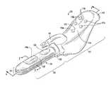
- FIG. 1is a perspective view of a stimulation device, shown according to an exemplary embodiment.
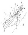
- FIG. 2is a perspective view of a portion of the device of FIG. 1 , shown according to an exemplary embodiment.
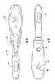
- FIG. 3is a bottom plan view of the device of FIG. 1 , shown according to an exemplary embodiment.
- FIG. 4is a top plan view of the device of FIG. 1 , shown according to an exemplary embodiment.
- FIG. 5is an exploded perspective view of a portion of the device of FIG. 1 , shown according to an exemplary embodiment.
- FIG. 6is a longitudinal cross-section view of the device taken along line 6 - 6 of FIG. 1 , shown according to an exemplary embodiment.
- FIG. 7Ais a radial cross-section view of the device taken along line 7 - 7 of FIG. 1 in a deflated state, shown according to an exemplary embodiment.
- FIG. 7Bis a radial cross-section view of the device taken along line 7 - 7 of FIG. 1 but showing the device in an inflated state, according to an exemplary embodiment.
- FIG. 8is a schematic block diagram of the device of FIG. 1 , shown according to an exemplary embodiment.
- FIG. 9is a schematic block diagram of the processing electronics of the device of FIG. 1 , shown according to an exemplary embodiment.
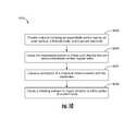
- FIG. 10is a schematic flow chart of a process for toning pelvic floor muscles, shown according to an exemplary embodiment.
- FIG. 11is a schematic flow chart of a process for toning pelvic floor muscles, shown according to another exemplary embodiment.
- FIG. 12is a schematic sagittal cross-sectional view of a user with the device of FIG. 1 in an inserted position, shown according to an exemplary embodiment.
- the device 101includes a handle 111 and a probe 121 , the probe 121 configured for insertion into a vagina.
- the probe 121includes an inflation member or balloon 125 having an outer surface 127 .
- the balloon 125may be configured to assume a plurality of states of expansion between minimum expansion and maximum expansion.
- a first electrode 129 a , a second electrode 129 b , and a first vibrating element [shown as a Gräfenberg Spot (G-Spot) stimulator 133 ]are disposed on the outer surface of the balloon 125 .
- a second vibrating element(shown as a clitoral stimulator 141 ) is shown disposed on the handle 111 .
- An inflation devicemay be located in the handle 111 and configured to cause the balloon 125 to inflate, in turn causing at least one of the electrodes 129 to press into contact with at least one vaginal wall.
- Processing electronics 801may be located in the handle 111 and configured to control the current and voltage provided to the electrodes 129 such that the electrodes 129 cause a contraction of a muscle in communication with an electrode 129 .
- the processing electronics 801may also be configured to control at least one aspect of one or more vibrating elements 133 , 141 .
- devices and methods described for toning pelvic floor musclesdeliver electrical pulses to stimulate muscle contraction to strengthen the muscles in the area of the pelvic floor. Electrical stimulation causes muscles to contract and release repeatedly, thereby strengthening those muscles. Toning and tightening pelvic floor muscles improves intimate health and may increase the power and intensity of the female orgasm. Electrical tissue stimulation may also provide a pleasurable sensation to the user. While the method and device are described for vaginal stimulation and pelvic floor toning, it is contemplated that this device may cause pleasurable sensations to a user or tone pelvic floor muscles via the anus and rectum, in which case, references to vagina would be modified accordingly.
- references to “front,” “rear,” “right,” and “left” in this descriptionare merely used to identify the various elements as they are oriented in the FIGURES, with “right,” “left,” “front,” and “rear” being relative to a specific direction. These terms are not meant to limit the element which they describe, as the various elements may be oriented differently in various applications.
- the term coupledmeans the joining of two members directly or indirectly to one another. Such joining may be stationary in nature or moveable in nature and/or such joining may allow for the flow of fluids, electricity, electrical signals, or other types of signals or communication between the two members. Such joining may be achieved with the two members or the two members and any additional intermediate members being integrally formed as a single unitary body with one another or with the two members or the two members and any additional intermediate members being attached to one another. Such joining may be permanent in nature or alternatively may be removable or releasable in nature.
- device 101may be used for causing a pleasurable sensation or toning pelvic floor muscles, specifically in women.
- device 101includes a housing, shown as handle 111 , and a probe 121 .
- Handle 111provides the user a region which may be grasped for control and manipulation of the device 101 and to facilitate insertion, positioning, and removal of probe 121 .
- Handle 111is shown to include a sleeve 113 configured to cover the majority of handle 111 .
- Sleeve 113is preferably pliable and provides a smooth and watertight surface to handle 111 wherein the smooth and watertight surface facilitates cleaning which is beneficial due to the handle's 111 proximity to bodily fluids and the vaginal opening during use.
- Sleeve 113may also be translucent to allow lights 172 , 178 (e.g., lamps, LEDs, displays, etc.) or a display (not shown) on handle 111 to shine through.
- Sleeve 113allows actuation of control inputs, shown as buttons 174 , located below sleeve 113 .
- sleeve 113may be customizable, e.g., bearing various colors or logos.
- sleeve 113is formed from silicone rubber.
- handle 111includes a first portion, shown as interface 115 , which includes a plurality of control inputs (e.g. toggles, switches, an electro-acoustic transducer configured to receive voice commands, a touch sensitive display, etc.), shown as buttons 174 , configured to enable user input into device 101 .
- button 174 amay be a power button configured to turn device 101 on and off.
- Button 174 amay be a combination power/mode button configured to turn device 101 on and off and to switch between operating states (e.g., vibrational patterns, pleasurable sensation versus muscle toning, etc.).
- buttons 174 bcontrol the frequency or speed of vibration
- buttons 174 cincrease or decrease the intensity of the electrical stimulation.
- buttons 174may provide other control inputs, for example, stimulation select, pressure select, increase, decrease, frequency, amplitude, current, voltage, pause, etc.
- interface 115includes a plurality of sequentially oriented lamps 178 (e.g., lights, LEDs, etc.) configured to indicate the level of electrical stimulation intensity.
- lamps 178may indicate a level of vibrational intensity or the pressure inside balloon 125 .
- Interface 115may also include a display (not shown) configured to numerically indicate balloon pressure, stimulation intensity, or vibrational intensity.
- the displaymay be further configured to display images, pictures, or videos (e.g., instructional or erotic images), or to display a waveform representative of the stimulation signal.
- the display and the plurality of lamps 178may indicate the same or different information.
- Interface 115may include a plurality of indicator lamps 172 (e.g.
- a power statee.g., power on, battery low, etc.
- a communication statee.g., communication to a computer, etc.
- pressure statee.g., the pressure inside balloon 125 has reached a predetermined value
- an error stateetc.
- interface 115may be located on a separate control unit.
- the control unitmay be coupled to handle 111 via cable 106 or configured to communicate with device 101 wirelessly, for example, using Bluetooth, wireless local area network, or personal area network protocols.
- any or all of the components of device 101may be located on or in the control unit.
- lamps 172 , 178 , control inputs 174 , and/or power supply 809e.g., batteries
- display 811e.g., audio device 813 , processing electronics 801 , and probe controller circuit 807 may be located in the control unit.
- pump 511may be located in controller 104 .
- probe 121generally has the form of an elongated cylinder having an open proximal end and a closed distal end. Probe 121 may include a neck portion 123 near the proximal end. Probe 121 includes a member or expandable portion, shown as balloon 125 .
- balloon 125includes a single inflatable balloon having an outer surface 127 .
- the expandable portionmay include a plurality of balloons. According to various embodiments, the plurality of balloons may be oriented axially, radially, circumferentially, or some combination thereof.
- Balloon 125may be formed of an airtight, elastic, biocompatible material, such as silicone rubber. According to alternate embodiments, balloon 125 may be formed of any suitable material.
- Probe 121is further shown to include at least one electrode 129 , shown as electrode 129 a (e.g., first electrode, top electrode, etc.).
- electrode 129is mounted to outer surface 127 of balloon 125 in such a manner that electrode 129 may come into contact with tissue adjacent to balloon 125 when probe 121 is in an inserted position.
- probe 121may include a second electrode 129 b (e.g., bottom electrode, etc.).
- First electrode 129 a and second electrode 129 bare shown radially opposite one another; however, probe 121 may have a plurality of electrodes 129 , the plurality of electrodes being located anywhere on probe 121 , e.g., left and right sides, both on top, axially or circumferentially offset, or equally or unequally spaced circumferentially around probe 121 .
- the relative position of the electrodes 129is dependent upon the particular tissue to receive the electrical stimulation. The placement and relative spacing of the electrodes will determine, in part, the effectiveness of the muscle contraction as a result of the electrical stimulation.
- a plurality of electrodes 129may be energized at the same time, different electrodes (e.g., a subset of a plurality of electrodes) may be actuated during different phases of an exercise or pleasurable sensation session, or different electrodes may be actuated during different sessions. For example, an even number of electrodes 129 may be actuated in pairs, or an odd number of electrodes may be actuated in a rotating pattern. Actuating different electrodes 129 at different times may cause different muscles to contract, thereby toning more and different pelvic floor muscles and preventing the muscles from becoming adjusted or de-sensitized to the electrical stimulation.
- a usermay select which electrodes 129 are actuated or may select a pattern or actuation of electrodes in order to provide a desired pleasurable sensation.
- position of electrodes 129may be chosen to facilitate manufacture of balloon 125 , for example, aligning electrodes 129 with G-Spot stimulator 133 may simplify mold design.
- the plurality of electrodes 129may have the same or different shape.
- Electrode 129is configured to deliver electrical pulses (e.g., signals, currents, voltages, frequencies, etc.) to stimulate muscle contraction to strengthen the muscles in the area of the pelvic floor. It is contemplated that the electrical stimulation provided to tone pelvic floor muscles may be different than the optimal stimulation to provide a pleasurable sensation.
- Electrode 129may also communicate a response information (e.g., a signal indicative of the contractive force of the muscles) to processing electronics 801 .
- the response informationis a voltage created by the contracting muscle.
- the response informationis an electric potential difference between first electrode 129 a and second electrode 129 b .
- the muscle contraction causing the response informationmay be caused by electrode stimulation of the muscle or may be the result of a manual contraction caused by the user.
- electrodes 129may be formed from stainless steel, and in another embodiment, the electrodes may be formed from an expandable, conductive silicone rubber or any other suitable material. It may be desirable to limit electrodes 129 from expanding so as to maintain a relatively consistent conductivity or to prevent the muscle stimulation from moving as balloon 125 is expanded. Further, electrodes formed of materials different than balloon 125 may not expand at the same rate as balloon 125 during inflation. Therefore, it may be beneficial to provide a balloon 125 which expands non-uniformly.
- electrode 129 ais supported by a first portion of balloon 125 .
- the first portion of balloon 125 and a second portion of balloon 125cooperate to cause balloon 125 to expand in a radially and/or circumferentially non-uniform manner relative to probe 121 .
- electrode 129 bis supported by a third portion of balloon 125 .
- the first and third portions of balloon 125cooperate to cause balloon 125 to expand in a radially and/or circumferentially non-uniform manner relative to probe 121 .
- Non-uniform expansion of balloon 125may cause balloon 125 to substantially contour to the anatomy of a user, for example, to conform to the contours of the user's vagina.
- Non-uniform expansion of balloon 125may also facilitate a suitable and comfortable fit of balloon 125 for the user.
- the second portionmay be an expansion portion (e.g., folds, pleats, articulation, etc.), shown as bellows 131 .
- the folds of bellows 131provide a region of increased surface area of balloon 125 in the deflated state, which allows balloon 125 to expand in a circumferentially non-uniform manner.
- bellows 131extend longitudinally or axially along the sides of balloon 125 .
- Bellows 131are further shown to extend around the distal end of balloon 125 .
- bellows 131are shown to extend substantially continuously around the midsection (e.g. equatorially region) of balloon 125 .
- bellows 131may extend discontinuously, in a top/bottom meridian formation, or in any suitable orientation to cause differential expansion of balloon 125 .
- Probe 121may include any number of bellows 131 equally or unequally spaced around probe 121 .
- bellows 131may be configured to provide an opening 603 through which wires 227 may pass when balloon 125 is in a deflated state.
- bellows 131are configured such that a majority of the expansion of balloon 125 occurs in the bellows region.
- FIG. 7Aa radial cross-section of probe 121 is shown in a first state (e.g., minimum expansion, contracted, deflated, etc.), whereas FIG. 7B shows a radial cross-section of probe 121 in a second state (e.g., expanded state, inflated, etc.).
- first statee.g., minimum expansion, contracted, deflated, etc.
- second statee.g., expanded state, inflated, etc.
- first and third portions of balloon 125are closely adjacent to or abut shaft 211 .
- bellows 131have substantially unfolded allowing radial expansion of the first and third portions of balloon 125 and electrodes 129 a and 129 b provided thereon.
- the first portion of balloon 125may have a first thickness 605
- the second portion of balloon 125may have a second thickness 607 , specifically thickness 605 of the first portion being greater than thickness 607 of the second portion. Accordingly, the first portion tends to resist circumferential expansion and maintain its form when balloon 125 is inflated.
- the second portionprovides a “path of least resistance” for expansion, such that for a prescribed level of inflation pressure, balloon 125 will stretch or expand the material of balloon 125 more in the second region than in the first region.
- balloon 125has a diameter of between approximately 1 inch and approximately 2 inches. Preferably, at minimum expansion, balloon 125 has a diameter of approximately 11 ⁇ 8 inches. According to one embodiment, at maximum expansion, balloon 125 has a diameter of between approximately 2 inches and approximately 4 inches, the preferred maximum expansion of balloon 125 being between approximately 3 inches and approximately 4 inches in diameter. Expansion of balloon 125 in these ranges enables contouring balloon 125 to women of different anatomical sizes.
- device 101is shown to have a first vibrating element, shown as a Gräfenberg Spot or G-Spot stimulator 133 , and a second vibrating element, shown as a clitoral stimulator 141 .
- Clitoral stimulator 141is in the shape of a curved projection or finger which extends outwardly from the outer surface 127 of balloon 125 adjacent neck 123 of balloon 125 . As shown in the figures, the projection curves in the distal direction (i.e., away from neck 123 of balloon 125 ).
- G-Spot stimulator 133is shown as a rounded projection or “bump.” G-Spot stimulator 133 extends a shorter distance outwardly from the surface of balloon 125 than clitoral stimulator 141 such that the height of clitoral stimulator 141 is greater than the height of G-Spot stimulator 133 . G-Spot stimulator 133 is located between distal end 213 of balloon 125 and clitoral stimulator 141 , and clitoral stimulator 141 is located between G-Spot stimulator 133 and the proximal end of the balloon. G-Spot stimulator 133 may be used to indicate to a user that probe 121 is properly inserted. For example, G-Spot stimulator 133 may provide a user a point of reference for internal positioning probe 121 .
- G-Spot stimulator 133includes a cavity 503 and clitoral stimulator 141 includes a cavity 535 .
- Cavities 503 and 535are configured to receive vibration actuators 533 and 537 , respectively, which are configured to cause vibration of the associated stimulator.
- cavities 503 and 537may be configured to receive a sensor (e.g., capacitive sensor, pressure sensor, conductivity sensor, etc.), which will be discussed further below.
- electrodes 129may be positioned along the outer surfaces of G-Spot stimulator 133 and clitoral stimulator 141 .
- device 101may include a single actuator that generates vibrations which are transmitted to balloon 125 , G-Spot stimulator 133 and clitoral stimulator 141 .
- the first vibrating elementis shown coupled or mounted just below the outer surface 127 of balloon 125 near proximal end 215 of balloon 125 .
- the material that forms the outer surfaces of the first vibrating elementis integral or continuous with the material of balloon 125 .
- the second vibrating elementis shown coupled or mounted to flange 201 on handle 111 and is discontinuous with the material of balloon 125 .
- the material of balloon 125 and the outer surfaces of the first and second vibrating elementsmay be any stretchable or expandable biocompatible material, and in one embodiment may be silicone rubber.
- Handle 111may be formed of a plurality of portions, such as a “clam shell” assembly. As shown, handle 111 includes a left portion 203 , a right portion 205 , and a bottom portion 207 , wherein left portion 203 and right portion 205 are hollow, substantially symmetric pieces of ABS plastic coupled together to form a housing.
- left portion 203 and right portion 205form a structure (e.g., base, support, etc.), shown as flange 201 which is configured to support clitoral stimulator 141 and to form a passage through which wires 227 c may pass into handle 111 .
- Bottom portion 207may include an inflation device, wherein bottom portion 207 is formed of a deformable material, for example, a silicone rubber which is sufficiently pliable to compress the inflation device and to return to shape.
- bottom portion 207may be a rigid portion movably coupled to left portion 203 and/or right portion 205 .
- Left portion 203 , right portion 205 , and bottom portion 207may be formed of any suitable material, may be formed of the same or different materials, or may be formed as one element. Portions of handle 111 may be coupled by snap fit, fastener, hinge, and/or any other suitable coupling technique. Handle 111 is further shown to include a release valve 209 , discussed in detail below, and a plurality of holes 271 configured to receive buttons 174 and lamps 172 , 178 .
- device 101includes a shaft 211 configured to house batteries used to power device 101 or components thereof.
- shaft 211is an elongated structure having a distal end 213 and a proximal end 215 , the proximal end 215 being coupled to handle 111 .
- shaft 211may be interconnected to a remote control unit via a cable.
- Shaft 211may include an operative region 217 located between proximal end 215 and distal end 213 , the operative region 217 being configured to be substantially located within the vagina when probe 121 is in an inserted position.
- Shaft 211may be solid, hollow, or any combination thereof.
- shaft 211includes a radially extending flange (e.g., collar), shown as bulkhead 219 .
- Bulkhead 219is configured to provide a substantially airtight seal between handle 111 and balloon 125 .
- bulkhead 219includes a first passage, shown as bottom passage 221 , and a second passage, shown as top passage 225 .
- Bottom passage 221may be configured to allow a conduit, shown as tube 223 , to extend from an inflation device into balloon 125 .
- a substantially airtight sealis preferably formed (e.g., with silicone glue) between tube 223 and bulkhead 219 .
- Top passage 225may be configured to allow wires 227 to pass from electrodes 129 and/or other sensors or motors into handle 111 . As shown, wires 227 a couple to electrodes 129 , and wires 227 b couple to G-Spot vibration actuator 533 . A substantially airtight seal may be formed (e.g., with silicone glue) between wires 227 and bulkhead 219 . Bulkhead 219 may have any number of passages, and the passages may have any orientation around shaft 211 . Alternatively, bulkhead 219 may include one passage for passing both tube 223 and wires 227 .
- tube 223 and/or wires 227may be routed through shaft 211 .
- Shaft 211may include perforations configured to allow pressurizing fluid pumped through shaft 211 to enter into balloon 125 . Routing pressurizing fluid, tube 223 , and/or wires 227 through shaft 211 may eliminate the need for passages 221 , 225 through bulkhead 219 . Accordingly, these passages may be removed in order to improve the airtight seal between handle 111 and balloon 125 .
- Handle 111includes a battery cap 303 configured to retain batteries 541 within shaft 211 . As shown, battery cap 303 cap forms an end portion of shaft 211 . According to alternate embodiments, battery cap 303 may be configured to allow wires 227 to pass out of handle 111 , for example, to a power outlet or to a remote control unit. Handle 111 is further shown to include structure such as air inlet 305 (or orifice, valve, grommet, etc.) for inflation of balloon 125 described further below.
- air inlet 305or orifice, valve, grommet, etc.
- the diameter of balloon 125may be substantially uniform over the length of probe 121 , or the diameter of balloon 125 may vary. As shown, proximal end 215 of balloon 125 has a first diameter, and distal end of balloon 125 has a second diameter, the second diameter being greater than the first diameter. According to one embodiment, probe 121 transitions from the first diameter to the second diameter between neck portion 123 and electrode 129 . According to the embodiment shown in FIGS. 3 and 6 , balloon 125 begins to transition from the first diameter to the second diameter proximate G-Spot stimulator 133 . Varying the diameter of balloon 125 along the length of probe 121 effects the expansion of balloon 125 along the length of probe 121 .
- the smaller proximal diameterlimits expansion at proximal end 215 while allowing greater expansion of balloon 125 near electrodes 129 and proximal end 212 , thereby contouring balloon 125 to the vaginal cavity. This further enables electrodes 129 to press against vaginal walls without applying excessive pressure on the introitus (vaginal entrance).
- balloon 125includes a depression, cavity, or pocket 403 configured to receive electrode 129 .
- a periphery of electrode 129is configured to seat into pocket 403 , and a sealant (e.g., silicone glue) may be used to couple electrode 129 to pocket 403 and to form a substantially airtight seal between electrode 129 and balloon 125 .
- a sealante.g., silicone glue
- Balloon 125is further shown to include an aperture, shown as hole 405 , which is configured to permit passage of wires 227 from electrode 129 to the interior of balloon 125 .
- a sealantmay be used to retain wires 227 in place and to form a substantially airtight seal between wires 227 and balloon 125 .
- probe 121comprises only one balloon 125 configured to surround operative region 217 of shaft 211 .
- singular balloon 125is shown to surround the entire portion of shaft 211 located within a vagina 21 when probe 121 is in an inserted position.
- FIG. 12schematically depicts an embodiment of the device depicted and generally described in relation to FIGS. 1-11 .
- the vibration element 141extends to a point in which it abuts or is in contact with the clitoris or the surrounding tissue.
- probe 121is in an inserted position when electrodes 129 are located within the vagina 21 or when G-Spot stimulator 133 is proximate a user's Gräfenberg Spot (G-Spot) 23 .
- G-SpotGräfenberg Spot
- device 101includes a printed circuit board 407 configured to be supported by left portion 203 and right portion 205 of handle 111 .
- circuit board 407is configured to support lamps 172 , 178 , input controls 174 , and processing electronic 801 .
- a power supply 809may be coupled to circuit board 407 and batteries 541 .
- Balloon 125is shown to define a lumen or cavity 531 , and cavity 531 is configured to receive shaft 211 .
- Balloon 125is shown to circumferentially surround at least a portion of shaft 211 .
- Probe assembly 102is shown to include an inflation device located at least partially within bottom portion 207 of handle 111 for selectively inflating and deflating balloon 125 .
- the inflation deviceincludes a pump 511 which may be manually operated.
- Pump 511includes a cavity within bottom portion 207 , shown as bladder 513 , and a first check valve 515 is located between bladder 513 and air inlet 305 .
- Check valve 515permits air to enter bladder 513 through air inlet 305 from outside of device 101 and prevents air from exiting back through air inlet 305 when bladder 513 is compressed.
- a second check valve 517is located between tee connector 519 and bladder 513 .
- Check valve 517permits air to enter tee connector 519 from bladder 513 and prevents air from back flowing into bladder 513 , for example, when bladder 513 expands.
- tee connector 519couples bladder 513 , release valve 209 , and tube 223 .
- Release valve 209may be of any suitable mechanism to permit air under pressure to be selectively released from balloon 125 , for example a thumbscrew or a pushbutton. Release valve 209 may also act as a relief valve to prevent over-pressurization of balloon 125 .
- Tube 223extends from an outlet of tee connector 519 through bulkhead 219 into probe 121 . In operation, squeezing bottom portion 207 compresses bladder 513 and forces air through tee connector 519 and tube 223 into balloon 125 .
- bladder 513When the squeezing force exerted on bladder 513 is released, bladder 513 will resume its natural, inflated position as air is drawn into bladder 513 through check valve 515 .
- Bladder 513is squeezed and released repeatedly to force pressurized air into balloon 125 .
- Increased pressure in balloon 125eventually causes inflation of balloon 125 , which in turn causes electrode 129 to contact a vaginal wall.
- the level of inflation of balloon 125is controlled by a user and may be selected to ensure a suitable and comfortable fit between balloon 125 and the user's vagina.
- the preferred level of inflationis stored in memory 921 of processing electronics 801 described below.
- the inflation devicemay include a motorized pump, the inflation device may be located in a remote control unit and pressurized air directed into balloon 125 through flexible tubing, and/or the inflation device may be located within probe 121 .
- the pressurizing fluid of the exemplary embodimentis air; however, any suitable pressurizing fluid may be used, for example, water, saline, oil, or other gases or liquids.
- device 101includes a pressure sensor barometrically connected to balloon 125 and located in probe 121 (e.g., in cavity 503 ), in handle 111 , or in the control unit.
- the pressure sensormay visually display an indication of a pressure inside balloon 125 on handle 111 , for example, a gauge, a light, a digital display, etc. Providing an indication of pressure enables a user to determine a preferred pressure and to repeatably return to that pressure.
- the pressure sensormay be configured to communicate (via wires or wirelessly) pressure information to processing electronics 801 .
- the pressure sensormay generate a response information (e.g., a signal indicative of the rise in pressure caused by contractive force of the muscles on balloon 125 ) triggered by the electrical stimulation provided by electrodes 129 or by the user manually (e.g., consciously, volitionally, voluntarily, etc.) forcing a contraction of her pelvic floor muscles.
- a response informatione.g., a signal indicative of the rise in pressure caused by contractive force of the muscles on balloon 125
- the electrical stimulationprovided by electrodes 129 or by the user manually (e.g., consciously, volitionally, voluntarily, etc.) forcing a contraction of her pelvic floor muscles.
- Tracking response informationenables a user to determine progress in pelvic floor muscle toning.
- neck portion 123 of probe 121includes an external annular groove 523 and an internal annular groove 525 .
- Internal annular groove 525is configured to fit over a radial periphery of bulkhead 219 , and a sealant (e.g., silicone glue) may be used between internal annular groove 525 and bulkhead 219 to form a substantially airtight seal.
- Proximate bulkhead 219 , left handle portion 203 and right handle portion 205cooperate to form a substantially cylindrical portion 527 and an inwardly extending annular flange 529 .
- Substantially cylindrical portion 527fits over neck portion 123 of probe 121 and helps to hold internal annular groove 525 against bulkhead 219 .
- Inwardly extending flange 529fits into external annular groove 523 of probe 121 . Accordingly, neck portion 123 and handle 111 are configured to prevent balloon 125 from slipping free of handle 111 .
- shaft 211is shown to be axially located within cavity 531 of probe 121 .
- shaft 211is configured to provide sufficient rigidity to probe 121 to facilitate insertion of probe 121 into a vagina.
- Shaft 211may include a plurality of portions (e.g., members, structures, regions, webs, etc.), shown as ribs 611 , configured to support balloon 125 .
- Ribs 611 amay support bellows 131 and inhibit bellows 131 from collapsing into cavity 531 .
- Balloon 125may include a plurality of structures (stiffeners, portions, etc.), shown as lugs 613 , which are shown to rest on ribs 611 b when balloon 125 is in a fully deflated state. Lugs 613 provide cushioning between shaft 211 and a user. Lugs 613 may also stiffen portions of balloon 125 underneath electrodes 129 , thereby reducing flexure of balloon 125 in the area of the electrode. As shown, bellows 131 , lugs 613 and ribs 611 are configured to cooperate to maintain a substantially round shape to probe 121 when balloon 125 is in a deflated state.
- a method for toning pelvic floor muscles in a femaleincludes inserting probe 121 into the vagina, pressurizing balloon 125 to inflate balloon 125 such that electrodes 129 contact the walls of the vagina (e.g., to place electrodes 129 snugly against the walls of the vagina to provide an electrical conduction pathway from the electrodes to the muscles and/or associated nerves), and periodically supplying a pulsed electrical stimulation to electrodes 129 to stimulate the muscles.
- balloon 125allows device 101 to ensure a proper fit with anatomies of different sizes.
- Device 101may include a pressure sensor configured to generate a signal indicative of the contractive force of the muscles on balloon 125 triggered by the electrical stimulation provided through the electrodes 129 .
- the signal from the pressure sensormay be communicated (e.g., via wired or wireless connections) to processing electronics 801 .
- Processing electronics 801may be configured to process the signal from the pressure sensor to determine information related to muscle contraction caused by the electrical stimulation (e.g., the force or strength of muscle contraction, the duration of muscle contraction, etc.).
- the air pressure within balloon 125causes balloon 125 to expand to original inflated size.
- the methodalso includes using a biphasic pulse.
- the progress of the toning exercisescan be monitored by evaluating the increase in strength of muscle activity by measuring muscle contraction over a number of exercise sessions. Toning exercises may be particularly useful for women who have recently given birth.
- device 101may be used three weeks after childbirth.
- a method for causing a pleasurable sensation in a usermay include similar steps as well as the steps of causing the vibration of clitoral and/or G-Spot stimulators.
- the pleasurable sensationmay be used to cause an orgasm, which in turn causes a release of serotonin and norepinephrine in the user which may improve the user's mood and treat depression, specifically post-partum depression.
- processing electronics 801supply a biphasic pulse of electrical current to electrodes 129 which in turn stimulates contraction of the muscles.
- the biphasic pulsemay have a first stimulation phase providing a pulse at 12 hertz for 6 seconds followed by a first rest period having a duration of 6 seconds.
- a second stimulation phase providing a pulse at 25 hertz for six secondsfollows the first rest period, and a second rest period having a duration of 6 seconds follows the second phase.
- the use of a biphasic pulse(e.g., a pulse having two stimulation periods having different frequencies) prevents the muscles from becoming adjusted or de-sensitized to the electrical stimulation.
- a multiphasic pulse(e.g., a plurality of different pulse durations and/or frequency between pulses) may be used.
- This sequence of stimulation phases and rest phasesrepeats for a treatment period as necessary.
- a typical treatment periodis approximately 15 minutes.
- other frequencies and/or durations for the stimulation phases and/or rest periodsmay be used.
- the frequency deliveredmay be variable, and frequencies up to 50 hertz may be delivered.
- a symmetric alternating currentmay be applied to the muscle via electrodes 129 to reduce the effects of electrophoresis or cataphoresis on the muscle tissues.
- applying a current of a positive first value for a first pulsewidthe.g., 200 microseconds
- applying no current for 40 microsecondsand then applying a current of a negative first value for a first value (e.g., 200 microseconds) limits the migration of ions with the muscle tissue.
- This pattern of alternating current pulsewidthsmay then be repeated at various frequencies (hertz), e.g., 12 hertz, 25 hertz, 50 hertz, etc. Accordingly, the amount of time between the end of the negative current until the beginning of the positive current depends on the frequency. Placing a short rest period (e.g., 40 microseconds) between the bipolar phases may improve circuit reliability.
- device 101may be operated at five different levels of electrical stimulation.
- the lowest level of electrical stimulationcorresponds to an electrical stimulation current of 10 milliamps, with each subsequent level increasing the electrical stimulation by 10 milliamps such that the second through fifth levels correspond to 20, 30, 40, and 50 milliamps, respectively.
- five lamps 178are illuminated to correspond with the current operating level of the corresponding stimulation element, and the electrical stimulation current is delivered in a series of electrical stimulation phases separated by rest periods as discussed above.
- electronics 801supply a biphasic pulse of electrical potential between electrodes 129 .
- the electrical potential between electrodes 129may have five different levels ranging between 10 Volts and 60 Volts.
- stimulationmay occur as low as 4-5 Volts. Contraction of the muscle is a function of current (or voltage) amplitude, pulsewidth, and frequency applied to the muscle. Further, the rate at which the muscle relaxes has a minimum persistence time that is affected by the strength and duration of the contraction. If the period (i.e., 1/frequency) of stimulation is greater than the minimum persistence time of the contraction, a user may perceive the stimulation as convulsions rather than a continuous contraction. Accordingly, processing electronics 801 may be configured to control one of frequency, pulsewidth, and amplitude in order to maintain a contraction perceived by the user as substantially continuous.
- processing electronics 801may be configured to control one of frequency, pulsewidth, and amplitude based on the other two in order to maintain a substantially continuous contraction. Additionally, processing electronics 801 may be configured to ramp at least one of frequency, amplitude, and pulsewidth at the beginning and/or end of each phase. Ramping the frequency, amplitude, and/or pulsewidth may reduce the step function of stimulation entering a phase, which may be uncomfortable or startling for some users. According to one embodiment, the pulsewidth may be stepped up by a fraction of the desired pulsewidth (e.g., 50 microseconds) per cycle until the desired pulsewidth (e.g., 200 microseconds) is reached. Processing electronics 801 may inhibit certain combinations of frequency, current, and voltage.
- the uservia a control 174 located on a remote control unit, may control the frequency of the electrical signal being supplied, may control the current delivered during each stimulation phase, or may control the voltage delivered during each stimulation phase.
- Device 101may also be operated at multiple, different levels of vibration stimulation intensity.
- the usermay control the amplitude of vibration generated by the first and second vibrating elements 133 , 141 to five different levels, and, in another embodiment, the user may control the frequency of vibration generated by the first and second vibrating elements 133 , 141 to five different levels.
- indication of vibration levelis provided haptically to the user (i.e., the user can feel the level of vibration); however, according to other embodiments, five lamps 178 may be illuminated to correspond with the present operating level of the corresponding vibrating element 133 , 141 .
- the first and second vibrating actuators 533 , 537may be controlled independently of each other, and, in this embodiment, interface 115 may include a first pair of vibration control buttons 174 that control vibrations of the first vibrating element 133 and a second pair of vibration control buttons 174 that control the vibration of the second vibrating element 141 . In another embodiment, both the first vibrating actuator 533 and the second vibrating actuator 537 are controlled together based upon the vibration level selected by the user by interacting with the vibration control buttons 174 .
- the level of stimulation and the level of vibrationare controllable independently and separately from each other via interaction with the independent stimulation and vibration control buttons 174 as discussed above.
- the level of electrical stimulation and the level of vibrationare controllable together such that the user can decrease and increase the level of electrical stimulation and the level of vibration together via interaction with a single set of controls.
- stimulation device 101may be one component of a stimulation device system that also includes a handheld display device.
- the handheld display deviceincludes a display screen and a set of display device controls.
- the handheld display devicemay be configured to display exciting or erotic material (e.g., videos, pictures, etc.) which may be viewed by the user while using the stimulation device.
- the handheld display devicemay include wireless communication hardware and/or wired communications hardware that allows the material to be downloaded from a source (e.g., the internet, a proprietary server, another local computer, etc.).
- the handheld display devicemay include a local memory device which stores the material to be displayed once it is downloaded.
- the handheld display devicemay also be configured to stream the material directly from the source. The user may control the display of the material (e.g., play, pause, rewind, fast-forward, etc.) via the display device controls.
- the handheld display devicemay be configured to communicate with the processing electronics 801 of the stimulation device via a communication link or connection.
- the operation of the stimulation device 101may be controlled based upon an aspect or property of the material displayed on the display device.
- the processing electronics 801may receive a signal from the handheld display device that provides information related to the aspect of the material being displayed, and the electronic control unit is configured to adjust the level of electrical and/or vibration stimulation based upon the provided information. For example, the level of electrical and/or vibration stimulation delivered by the stimulation device may be altered based on the nature of a scene of the video being displayed.
- the operation of the display devicemay be controlled based upon operation of the stimulation device 101 .
- a signal indicative of an operating parameter of the stimulation device 101may be communicated to the display device, and the operation of the display device may be controlled based upon the operating parameter.
- a corresponding signalmay be transmitted to the display device causing the display device to power on.
- turning the stimulation device off by pressing the power button on the electronic control unitmay trigger a signal to be generated to the display device which causes the video to be paused.
- Device 101is shown to include a pump 511 , electrode 129 , sensors 803 , and vibrating elements 805 .
- Pump 511is configured to cause inflation of balloon 125 and may be manually operated or motorized.
- First electrode 129 a and/or second electrode 129 bare configured to provide an electrical signal (e.g., current, voltage, frequency, etc.) to a muscle in communication with the electrode.
- device 101may have one or a plurality of electrodes 129 and may include one or more sensors 803 (e.g., a capacitive sensor, a pressure sensor, a conductivity sensor, etc.).
- Sensors 803may be disposed in any suitable location in device 101 (e.g., in handle 111 , in cavity 503 under G-Spot stimulator 133 , etc.).
- Vibrating elements 805e.g., G-Spot stimulator 133 , clitoral stimulator 141 , actuation motors 533 , 537 , etc.
- the pleasurable sensationmay induce a user to maintain compliance with an exercise regimen.
- device 101is shown to include control inputs 174 , lamps 178 , 172 , display 811 , audio device 813 , processing electronics 801 , probe controller circuit 807 , and power supply 809 .
- the control inputsmay include any suitable user interface, e.g., buttons 174 , toggles, switches, an electro-acoustic transducer configured to receive voice commands, a touch sensitive display, etc.
- Lampssuch as lamps 178 , 172 may provide information to a user through illumination, brightness, color, blinking pattern, and/or illumination of a subset of a plurality of spatially oriented lamps.
- Display 811may also be configured to provide alphanumeric or graphical images and may include a touchscreen (e.g., touch sensitive surface), the touchscreen being configured to both provide information to a user and to receive input from a user. Using a touchscreen would provide an easy to clean surface, thereby facilitating sanitary hygiene.
- Audio device 813may be a speaker configured to provide aural information to a user and may be combined with or separate from the electro-acoustic transducer control input. Audio device 813 may be configured to provide motivation and/or audio instruction to a user, to announce that the pressure inside balloon 125 has reached a predetermined level, or to request a user to manually force a contraction of the muscle in communication with electrodes 129 .
- Probe controller circuit 807may include any number of mechanical or electrical circuitry components or modules for a pump 511 , electrode 129 , sensors 803 , and/or vibrating elements 805 of device 101 .
- circuit 807may be configured to send electrical signals to pelvic floor muscles while sending response information to processing electronics 801 .
- Device 101is further shown to include a power supply 809 .
- Power supply 809is configured to provide electrical power to device 101 and components thereof.
- device 101is configured to be powered by a 6 Volt source (e.g. four AA batteries located in shaft 211 or a 6-Volt battery).
- device 101may use other voltages, a rechargeable battery, or may be plugged into utility power supply.
- Power supply 809 or processing electronics 801may be configured to increase the voltage and/or amperage available to electrodes 129 .
- the maximum electrical potential generated between the first electrode 129 a and second electrode 129 bis approximately 80 Volts.
- the maximum therapeutic range of the electrical potential generated between first electrode 129 a and second electrode 129 bis approximately 50 Volts.
- power supply 809 and/or processing electronics 801are configured to provide power to 3-Volt motors used in vibrating elements 805 .
- Processing electronics 801includes a processor 911 and a memory 921 .
- processor 911is configured to execute computer code stored in memory 921 to complete and facilitate the activities described herein.
- memory 921is shown to include modules 923 - 941 which are computer code modules (e.g., executable code, object code, source code, script code, machine code, etc.) configured for execution by processor 911 .
- processing electronics 801is configured to complete the activities described herein.
- Processing electronicsincludes hardware circuitry for supporting the execution of the computer code of modules 923 - 941 .
- processing electronics 801includes hardware interfaces (e.g., output 951 ) for communicating control signals (e.g., analog, digital) from processing electronics 801 to circuit 807 .
- Processing electronics 801may also include an input 956 for receiving, for example, sensor data from circuit 807 , response information from circuit 807 , user inputs from control inputs 174 , or for receiving data or signals from other systems or devices.
- processor 911may be or include one or more microprocessors, an application specific integrated circuit (ASIC), a circuit containing one or more processing components, a group of distributed processing components, circuitry for supporting a microprocessor, or other hardware configured for processing.
- Memory 921can be any volatile or non-volatile memory device capable of storing data or computer code relating to the activities described herein.
- Memory 921includes a memory buffer 923 for receiving sensor data, for example response information, pressure data, voltage data, capacitive sensing data, conductivity data, etc.
- the sensor datamay be stored in memory buffer 923 until buffer 923 is accessed for data.
- a program module 929 , electrode module 931 , vibration 933 , conductivity module 935 , inflation module 937 , position module 939 , pressure module 941 , or another process that uses sensor datamay access buffer 923 .
- the sensor data stored in memory 921may be stored according to a variety of schemes or formats.
- the sensor datamay be stored as streaming data, peak values, synchronous, asynchronous, separate buffers for each data type, one buffer for all sensor data, or any other suitable format for storing sensor information.
- Configuration data 925includes data relating to device 101 , such as electrode information that the electrode module 931 can interpret to determine how to command the electrodes 129 to cause a muscle contraction, for example the number of electrodes, electrode conductivity, conductivity as a function of expansion or pressure, etc.
- configuration data 925may include pump information, such as whether the pump 511 is hand-operated or motorized, and control information of the motorized pump.
- configuration data 925may include sensor information, such as the existence, location, and calibration of pressure sensors, conductivity sensors, capacitive sensors, and the like.
- configuration data 925may include response information configuration data which program module 929 can interpret to determine if the response information will include an electrical signal received from at least one of the electrodes 129 , a pressure signal received from a pressure sensor, or both.
- Memory 921further includes a program data 927 which includes data relating to the toning program or stimulation program.
- Program data 927may include data that program module 929 can interpret to determine how to command the electrical signal sent to electrodes 129 .
- program data 927may include electrical stimulation data including data relating to current, voltage, frequency, number of phases of stimulation signal, duration and pattern of stimulation periods, and/or duration and pattern of rest periods.
- Program data 927may include vibrational stimulation data including data relating to vibration, frequency, pattern, etc.
- Program data 927may be stored in memory 921 by the user or another, may be downloaded into memory 921 , and may be synchronized with audio or video files.
- Memory 921further includes a program module 929 which includes logic for using configuration data 925 , program data 927 , sensor data from the memory buffer 923 , and/or data received from another module to carry out the pleasurable sensations or muscle toning program, e.g., providing stimulation commands to electrode module 931 or vibration module 933 .
- Program module 929may output data to a data logging module for recording, may cause outputs for providing an indication to a user, and may cause an output requesting a user to perform an activity (e.g., inserting probe 121 , pressurizing balloon 125 , forcing a contraction, etc.).
- Program module 929may include logic to cause closed-loop control of the electrical stimulation and/or vibrational stimulation based on response information received from memory buffer 923 , electrode module 931 , conductivity module 935 , and/or pressure module 941 .
- Memory 921further includes an electrode module 931 which includes logic for causing a contraction of a muscle in communication with electrode 129 .
- Electrode module 931may control the stimulation of a muscle in communication with electrodes 129 based on conductivity information received from conductivity module 935 , position information received from position module 939 , and/or pressure information received from pressure module 941 .
- Electrode module 931may include logic to control the current or voltage provided by electrodes 129 as a function of frequency, or to control the frequency in response to the current or voltage.
- electrode module 931may be configured to operate at five levels of stimulation, which may be indicated to a user using the five lamps 178 shown on interface 115 .
- electrode module 931may include logic to use an 8-bit register to control the frequency, current, or voltage of the stimulation. Using an 8-bit register provides fine resolution for precise stimulation effects and toning.
- Memory 921further includes a vibration module 933 which includes logic for causing a vibrating element to vibrate.
- Vibration module 933may include logic for actuating G-Spot vibration actuator 533 , clitoral vibration actuator 537 , and a haptic feedback motor.
- actuators 533 and 537may be actuated dependently or independently and may be actuated in response to user input through controls 174 , in response to response information, or synchronized with music or video.
- Vibration module 933may operate actuators 533 and 537 at five different levels of vibration.
- Vibration module 933may receive data from memory buffer 923 , program data 927 , and program module 929 .
- Memory 921is shown to include a conductivity module 935 which includes logic for determining the conductivity of the environment of probe 121 , balloon 125 , and/or electrodes 129 .
- Conductivity of the environmentis dependent on many factors. For example, conductivity may depend on the conductivity and quantity of artificial lubricants used, the quantity of vaginal fluid present, which may change from day to day or during use, and/or the expansion of electrodes 129 .
- a conductivity sensor in probe 121may measure the resistivity between electrodes 129 or measure the current delivered for a provided voltage. According to one embodiment, a low voltage (e.g., 2 Volts) may be provided across electrodes 129 , the resulting current is measured, and resistance is calculated.
- a low voltagee.g., 2 Volts
- the low voltagemay be provided before beginning a toning or exercise program or may be provided during a portion of a rest period (e.g., between phases).
- Conductivity module 935may receive sensor data directly or through memory buffer 923 .
- Conductivity module 935may provide conductivity information to electrode module 931 or any other module requiring conductivity information.
- Memory 921is shown to include an inflation module 937 which includes logic for providing an indication to a user that the pressure inside balloon 125 has reached a predetermined value.
- the predetermined valueis a pressure stored in program data 927 .
- Inflation module 937may use sensor data from memory buffer 923 or pressure information from pressure module 941 .
- Inflation module 937may include logic for causing inflation of balloon 125 .
- inflation module 937may cause a request for a user to actuate pump 511 or may cause actuation of a motorized pump 511 .
- Inflation module 937may control pump 511 using configuration data 925 and pressure data received from memory buffer 923 or pressure module 941 .
- Memory 921is shown to include a position module 939 which includes logic for determining if probe 121 is inserted and/or properly positioned.
- position module 939may receive capacitive sensor data from memory buffer 923 .
- position module 939may determine insertion of probe 121 from a change in continuity or a change in resistance between electrodes 129 .
- position module 939may request user confirmation that probe 121 and/or balloon 125 are inserted, for example, by providing input via control inputs 174 on controller 104 .
- Position module 939may cause output from electrode module 931 to be inhibited if position module 939 determines that balloon 125 has been removed from the vagina.
- position module 939may cause electrodes 129 to stop providing an electric signal, or position module 939 may provide position information to program module 929 or to electrode module 931 .
- Memory 921further includes a pressure module 941 which includes logic for determining the pressure inside balloon 125 .
- Pressure module 941may use configuration data 925 , pressure data received directly from the pressure sensor, or pressure data received from memory buffer 923 .
- Pressure module 941may provide pressure information to inflation module 937 and program module 929 .
- Pressure module 941may provide pressure information to electrode module 931 , or may inhibit processing electronics 801 from causing a contraction of the muscle if the pressure in balloon 125 is below a threshold value, e.g., balloon 125 has not been sufficiently inflated.
- Pressure module 941may receive response information from the pressure sensor.
- Process 1001is shown to include the steps of providing a device as described above and including an expandable portion having an outer surface, a first electrode, and a second electrode (step 1003 ).
- Process 1001further includes the steps of causing the expandable portion to inflate such that the first and second electrodes contact vaginal walls (step 1003 ), and causing a contraction of the muscle in communication with the electrodes (step 1007 ).
- Process 1001further includes causing a vibrating element to impart vibration to a first potion of a user's body (step 1009 ).
- the first and second electrodescouple to the outer surface of the expandable portion and are configured to cause a contraction of a muscle and communication with the electrodes.
- process 1001may include additional or fewer steps.
- process 1001may include inserting the expandable portion in a vaginal cavity, deflating the expandable portion, and removing the probe from the vaginal cavity and may not include causing a vibrating element to impart vibration (step 1009 ).
- Process 1101is shown to include the steps of providing a device as described above and including a balloon having an outer surface, a first electrode, and a second electrode (step 1103 ) and inserting the balloon into a vaginal cavity (step 1105 ).
- Process 1101further includes the steps of causing inflation of the balloon such that at least one of the first and second electrodes press against at least one vaginal wall (step 1107 ) and causing the balloon to inflate in a radially non-uniform manner (step 1109 ).
- step 1107may include requesting a user to actuate pump 511 , causing actuation of pump 511 , and/or causing operation of a motorized pump.
- Step 1109may include unfolding of bellows or non-uniform expansion of balloon portions having different thicknesses.
- Process 1101is shown to include the steps of providing a pattern of at least one of current, voltage, and frequency (step 1111 ), causing a contraction of a muscle in communication with the electrodes (step 1113 ), causing a first vibrating element to impart vibration to a first portion of a user's body (step 1115 ), and causing a second vibrating element to impart vibration to a second portion of a user's body (step 1117 ).
- Providing the pattern in step 1111may or may not cause the contraction or vibrations in steps 1113 - 1117 , and the contraction and vibrations in steps 1113 - 1117 may be caused by the same or different electrical signals.
- Causing a contraction of a muscle in step 1113may be through electrical stimulation via electrodes 129 or may be requesting a user to manually or volitionally force a contraction of the muscle.
- the balloonmay then be deflated (step 1119 ) and removed from the vaginal cavity (step 1121 ).
- Process 1101may not include all of the steps listed, e.g., not include causing first or second vibrating elements to impart vibration (steps 1115 and 1117 ).
- Process 1101may include additional steps, e.g., lubricating the balloon or requesting insertion of the balloon into a vaginal cavity, for example, by indicating that device 101 is initialized and ready for insertion (e.g., illuminating in indicator lamp 172 ), providing an aural request through speaker audio device 813 , or providing instructions along with providing device 101 .
- additional stepse.g., lubricating the balloon or requesting insertion of the balloon into a vaginal cavity, for example, by indicating that device 101 is initialized and ready for insertion (e.g., illuminating in indicator lamp 172 ), providing an aural request through speaker audio device 813 , or providing instructions along with providing device 101 .
- the present disclosurecontemplates methods, systems and program products on any machine-readable media for accomplishing various operations.
- the embodiments of the present disclosuremay be implemented using existing computer processors, or by a special purpose computer processor for an appropriate system, incorporated for this or another purpose, or by a hardwired system.
- Embodiments within the scope of the present disclosureinclude program products comprising machine-readable media for carrying or having machine-executable instructions or data structures stored thereon.
- Such machine-readable mediacan be any available media that can be accessed by a general purpose or special purpose computer or other machine with a processor.
- machine-readable mediacan comprise RAM, ROM, EPROM, EEPROM, CD-ROM or other optical disk storage, magnetic disk storage or other magnetic storage devices, or any other medium which can be used to carry or store desired program code in the form of machine-executable instructions or data structures and which can be accessed by a general purpose or special purpose computer or other machine with a processor.
- a network or another communications connectioneither hardwired, wireless, or a combination of hardwired or wireless
- any such connectionis properly termed a machine-readable medium.
- Machine-executable instructionsinclude, for example, instructions and data which cause a general purpose computer, special purpose computer, or special purpose processing machines to perform a certain function or group of functions.
Landscapes
- Health & Medical Sciences (AREA)
- Life Sciences & Earth Sciences (AREA)
- Veterinary Medicine (AREA)
- Public Health (AREA)
- General Health & Medical Sciences (AREA)
- Animal Behavior & Ethology (AREA)
- Rehabilitation Therapy (AREA)
- Physical Education & Sports Medicine (AREA)
- Pain & Pain Management (AREA)
- Epidemiology (AREA)
- Reproductive Health (AREA)
- Engineering & Computer Science (AREA)
- Biomedical Technology (AREA)
- Nuclear Medicine, Radiotherapy & Molecular Imaging (AREA)
- Radiology & Medical Imaging (AREA)
- Gastroenterology & Hepatology (AREA)
- Heart & Thoracic Surgery (AREA)
- Cardiology (AREA)
- Electrotherapy Devices (AREA)
- Percussion Or Vibration Massage (AREA)
Abstract
Description
Claims (21)
Priority Applications (3)
| Application Number | Priority Date | Filing Date | Title |
|---|---|---|---|
| US13/458,734US8784345B2 (en) | 2010-06-17 | 2012-04-27 | Stimulation device and method |
| US14/336,555US9655808B2 (en) | 2010-06-17 | 2014-07-21 | Urinary incontinence device and method and stimulation device and method |
| US15/598,530US10517790B2 (en) | 2010-06-17 | 2017-05-18 | Urinary incontinence device and method and stimulation device and method |
Applications Claiming Priority (4)
| Application Number | Priority Date | Filing Date | Title |
|---|---|---|---|
| US35582210P | 2010-06-17 | 2010-06-17 | |
| US201161430072P | 2011-01-05 | 2011-01-05 | |
| PCT/US2011/040714WO2011159906A2 (en) | 2010-06-17 | 2011-06-16 | Urinary incontinence device and method and stimulation device and method |
| US13/458,734US8784345B2 (en) | 2010-06-17 | 2012-04-27 | Stimulation device and method |
Related Parent Applications (1)
| Application Number | Title | Priority Date | Filing Date |
|---|---|---|---|
| PCT/US2011/040714ContinuationWO2011159906A2 (en) | 2010-06-17 | 2011-06-16 | Urinary incontinence device and method and stimulation device and method |
Related Child Applications (1)
| Application Number | Title | Priority Date | Filing Date |
|---|---|---|---|
| US14/336,555ContinuationUS9655808B2 (en) | 2010-06-17 | 2014-07-21 | Urinary incontinence device and method and stimulation device and method |
Publications (2)
| Publication Number | Publication Date |
|---|---|
| US20120215141A1 US20120215141A1 (en) | 2012-08-23 |
| US8784345B2true US8784345B2 (en) | 2014-07-22 |
Family
ID=45348870
Family Applications (5)
| Application Number | Title | Priority Date | Filing Date |
|---|---|---|---|
| US13/458,734ActiveUS8784345B2 (en) | 2010-06-17 | 2012-04-27 | Stimulation device and method |
| US13/458,857Expired - Fee RelatedUS8369953B2 (en) | 2010-06-17 | 2012-04-27 | Urinary incontinence device and method |
| US13/739,750ActiveUS8818512B2 (en) | 2010-06-17 | 2013-01-11 | Urinary incontinence device and method |
| US14/336,555Expired - Fee RelatedUS9655808B2 (en) | 2010-06-17 | 2014-07-21 | Urinary incontinence device and method and stimulation device and method |
| US15/598,530Active2032-01-24US10517790B2 (en) | 2010-06-17 | 2017-05-18 | Urinary incontinence device and method and stimulation device and method |
Family Applications After (4)
| Application Number | Title | Priority Date | Filing Date |
|---|---|---|---|
| US13/458,857Expired - Fee RelatedUS8369953B2 (en) | 2010-06-17 | 2012-04-27 | Urinary incontinence device and method |
| US13/739,750ActiveUS8818512B2 (en) | 2010-06-17 | 2013-01-11 | Urinary incontinence device and method |
| US14/336,555Expired - Fee RelatedUS9655808B2 (en) | 2010-06-17 | 2014-07-21 | Urinary incontinence device and method and stimulation device and method |
| US15/598,530Active2032-01-24US10517790B2 (en) | 2010-06-17 | 2017-05-18 | Urinary incontinence device and method and stimulation device and method |
Country Status (7)
| Country | Link |
|---|---|
| US (5) | US8784345B2 (en) |
| EP (1) | EP2582430B1 (en) |
| CN (1) | CN103096973B (en) |
| AU (1) | AU2011268245B2 (en) |
| CA (1) | CA2838506C (en) |
| RU (3) | RU2597803C2 (en) |
| WO (1) | WO2011159906A2 (en) |
Cited By (12)
| Publication number | Priority date | Publication date | Assignee | Title |
|---|---|---|---|---|
| US20140330178A1 (en)* | 2010-06-17 | 2014-11-06 | InControl Medical, LLC | Urinary incontinence device and method and stimulation device and method |
| US20160184178A1 (en)* | 2012-09-07 | 2016-06-30 | Ovo Joint Venture, LLC | Stimulation device |
| US20170027814A1 (en)* | 2014-04-01 | 2017-02-02 | Korea Institute Of Industrial Technology | Display device |
| US10646711B2 (en) | 2016-01-29 | 2020-05-12 | Brent C. Reider | Interactive muscle training system and method |
| US10814139B2 (en)* | 2016-05-26 | 2020-10-27 | Advino Technologies | Low energy photonic laser device |
| US11027120B2 (en) | 2018-09-28 | 2021-06-08 | InControl Medical, LLC | Urinary incontinence treatment device and method for using the same |
| US11234894B2 (en) | 2011-04-05 | 2022-02-01 | Pelvital Usa, Inc. | Apparatus, system, and method for testing and exercising the pelvic floor musculature |
| US11724100B2 (en) | 2016-01-29 | 2023-08-15 | Brent C. Reider | Regulated and interactive muscle stimulation using sensory regulated EMG triggered stimulation for forging neural pathways |
| US11844736B2 (en) | 2017-12-13 | 2023-12-19 | Pelvital Usa, Inc. | Apparatus, system, and method for tissue regeneration |
| US11865337B2 (en) | 2016-01-29 | 2024-01-09 | Brent C. Reider | Regulated and interactive muscle stimulation |
| US20250152937A1 (en)* | 2025-01-16 | 2025-05-15 | Shulin Chen | Circuit Module for Pelvic Floor Muscle Rehabilitation Device and Pelvic Floor Muscle Rehabilitation Device |
| US12403064B1 (en)* | 2024-07-26 | 2025-09-02 | Shenzhen Useeker Technology Co., Ltd | Massager |
Families Citing this family (118)
| Publication number | Priority date | Publication date | Assignee | Title |
|---|---|---|---|---|
| CA2665465C (en) | 2006-08-30 | 2015-06-30 | Ohmea Medical Technologies, Inc. | Therapeutic devices for the treatment of various conditions of a female individual |
| AU2010280361B2 (en) | 2009-08-04 | 2015-10-08 | Pollogen Ltd. | Cosmetic skin rejuvination |
| US11590346B2 (en)* | 2009-11-16 | 2023-02-28 | Pollogen Ltd. | Apparatus and method for cosmetic treatment of human mucosal tissue |
| EP2501352B1 (en) | 2009-11-16 | 2016-07-13 | Pollogen Ltd | Device for non-invasive fat reduction comprising an applicator head with massage contacts and with electrodes |
| EP2699321B1 (en)* | 2011-04-19 | 2021-11-10 | Analytica Limited | An intra vaginal device to aid in training and determining muscle strength |
| US9615994B2 (en)* | 2011-07-06 | 2017-04-11 | LELO Inc. | Motion-based control for a personal massager |
| WO2013067367A1 (en) | 2011-11-04 | 2013-05-10 | Ohmera Medical Technologies, Inc. | Systems and methods for therapeutic treatments of various conditions of a female person |
| US20150112231A1 (en) | 2011-11-28 | 2015-04-23 | Remendium Labs Llc | Treatment of fecal incontinence |
| US20150112230A1 (en) | 2011-11-28 | 2015-04-23 | Remendium Labs Llc | Treatment of male urinary incontinence and sexual dysfunction |
| CA3222966A1 (en) | 2012-01-30 | 2013-08-08 | Axena Health, Inc. | Treatment of pelvic organ prolapse |
| GB2499585B (en)* | 2012-02-20 | 2014-05-07 | Cyrex Ltd | Apparatus for stimulating living tissue |
| US10130550B2 (en) | 2012-03-14 | 2018-11-20 | Ralph Zipper | Sexual stimulation device using light therapy, vibration and physiological feedback |
| CN104284648B (en) | 2012-03-14 | 2017-01-11 | 拉尔夫·齐珀 | Improved sexual stimulation device using light therapy and vibration |
| US10413473B2 (en) | 2012-03-14 | 2019-09-17 | Ralph Zipper | Sexual stimulation device using light therapy, vibration and physiological feedback |
| US9248285B2 (en) | 2012-06-09 | 2016-02-02 | Fempulse, Llc | Devices and methods for stimulating nerves |
| US8914111B2 (en) | 2012-06-09 | 2014-12-16 | Fempulse, Llc | Devices and methods for stimulating nerves |
| US8788040B2 (en) | 2012-06-09 | 2014-07-22 | Fempulse, Llc | Devices and methods for stimulating nerves |
| WO2015058128A1 (en)* | 2013-10-17 | 2015-04-23 | Fempulse, Llc | Devices and methods for stimulating nerves |
| US9381351B2 (en) | 2012-06-09 | 2016-07-05 | Fempulse, Llc | Devices and methods for stimulating nerves |
| DE102012105466B4 (en)* | 2012-06-22 | 2014-10-23 | Amor Gummiwaren Gmbh | vibrator |
| CN102743275B (en)* | 2012-07-24 | 2014-04-09 | 爱侣健康科技有限公司 | Mouse roller type sexual massager |
| WO2014037045A1 (en)* | 2012-09-06 | 2014-03-13 | Senses Toys Intellectual Property Management Ug | Stimulation device |
| WO2014043263A1 (en) | 2012-09-11 | 2014-03-20 | Shahoian Erik J | Systems and methods for haptic stimulation |
| US9022925B2 (en)* | 2012-09-27 | 2015-05-05 | Nanma Manufacturing Co., Ltd. | Massage apparatus having a sleeve with a lubrication well |
| EP2764888B1 (en)* | 2013-02-06 | 2016-07-13 | Beacmed S.r.L. | A perineal probe |
| US10327983B2 (en)* | 2013-02-21 | 2019-06-25 | Heather B. Enterprises, LLC | Ganja vibe |
| WO2014127530A1 (en)* | 2013-02-22 | 2014-08-28 | Chen Qingyue | Female apparatus |
| GB201306369D0 (en) | 2013-04-09 | 2013-05-22 | Photocure As | Irradiation device |
| US9737457B2 (en)* | 2013-04-16 | 2017-08-22 | Eugene Allen | Sexual appliances providing improved stimulation of Grafenberg area |
| US9889066B2 (en) | 2013-07-01 | 2018-02-13 | Good Fortune 5, Llc | Massaging device having a heat sink |
| USD829323S1 (en)* | 2013-12-04 | 2018-09-25 | Rhonda M. Hunt | Incontinence device |
| CN103691060B (en)* | 2013-12-30 | 2016-01-27 | 深圳先进技术研究院 | Electrical stimulation device |
| AU2015203940A1 (en) | 2014-01-06 | 2016-07-21 | Remendium Labs Llc | System and method for Kegel training |
| US9364667B1 (en)* | 2014-03-31 | 2016-06-14 | Elassia LLC | Potentiating or eliciting an erotic sensation in a body using electrostimulation |
| WO2016038469A2 (en)* | 2014-09-13 | 2016-03-17 | Standard Innovation Sarl | Devices and methods for sexual wellness |
| US9345874B2 (en) | 2014-10-23 | 2016-05-24 | BEACMED S.r.L. | Perineal probe |
| US10154832B2 (en)* | 2014-11-19 | 2018-12-18 | Danzhi Cai | Semen collection device |
| US20160136038A1 (en)* | 2014-11-19 | 2016-05-19 | Danzhi Cai | Massage device |
| US20160136036A1 (en)* | 2014-11-19 | 2016-05-19 | Danzhi Cai | Massage device |
| US20160136037A1 (en)* | 2014-11-19 | 2016-05-19 | Danzhi Cai | Pressing contact module and massage device using the same |
| CN104757960B (en)* | 2015-01-14 | 2017-09-26 | 天津榕丰科技有限公司 | Multiple protector and its control method in a kind of pneumatic type isolated pressure detection |
| USD739547S1 (en)* | 2015-02-12 | 2015-09-22 | Brandcore Ltd. | G-spot rabbit vibrator |
| USD743570S1 (en)* | 2015-02-12 | 2015-11-17 | Brandcore Ltd. | Classic rabbit vibrator |
| USD739548S1 (en)* | 2015-02-12 | 2015-09-22 | Brandcore Ltd. | Beaded rabbit vibrator |
| US9668934B2 (en) | 2015-05-15 | 2017-06-06 | Christine Pearson | Female sexual stimulation device |
| US10940079B2 (en) | 2015-05-19 | 2021-03-09 | Sparq Laboratories, Llc | Male and female sexual aid with wireless capabilities |
| FR3038841A1 (en)* | 2015-07-15 | 2017-01-20 | Akse | PROBE DEVICE FOR THE MANAGEMENT OF URINARY INCONTINENCE AT THE EFFORT |
| US20170027741A1 (en)* | 2015-07-28 | 2017-02-02 | Lawrence Bruce | Method and apparatus for inducing micturition |
| US20170087049A1 (en)* | 2015-09-29 | 2017-03-30 | Timothy Daniel HUTCHISON | Modular adult toy |
| DE102015119479A1 (en)* | 2015-11-11 | 2017-05-11 | Fun Factory Gmbh | Massage toy with two independent drives |
| CN108366828B (en)* | 2015-12-16 | 2022-04-15 | 保隆恩有限公司 | Apparatus and method for cosmetic treatment of human mucosal tissue |
| US20170291007A1 (en)* | 2016-04-06 | 2017-10-12 | Sonusmed, Incorporated | Therapeutic Vibration System |
| WO2017210870A1 (en)* | 2016-06-07 | 2017-12-14 | 东莞艮顺电子科技有限公司 | Pelvic floor muscle therapy system, probe apparatus and method of use thereof |
| KR20190043528A (en)* | 2016-07-07 | 2019-04-26 | 비너스 컨셉트 리미티드 | Beauty device and method useful for increasing skin rehabilitation |
| ES1162833Y (en)* | 2016-07-08 | 2016-11-08 | Ecareyou Innovation S L | Device to exercise the pelvic floor muscles. |
| USD817507S1 (en)* | 2016-07-28 | 2018-05-08 | Brandcore Ltd. | Vibrator |
| USD818143S1 (en)* | 2016-07-28 | 2018-05-15 | Brandcore Ltd. | Vibrator |
| USD818142S1 (en)* | 2016-07-28 | 2018-05-15 | Brandcore Ltd. | Vibrator |
| JP7242524B2 (en) | 2016-07-29 | 2023-03-20 | レノビア インコーポレイテッド | Devices, systems and methods for training pelvic floor muscles |
| US10835745B2 (en) | 2016-08-17 | 2020-11-17 | Pui Ling TAM | Non-invasive device and method for stimulating vulvar tissues and pelvic floor muscles for treating and improving dysfunction or disorders and probe unit used therefor |
| US11896824B2 (en) | 2016-10-05 | 2024-02-13 | Stimvia S.R.O. | Method for neuromodulation treatment of low urinary tract dysfunction |
| US11420052B2 (en)* | 2016-10-05 | 2022-08-23 | Tesla Medical S.R.O | Device and method for neuromodulation treatment |
| CN106390378A (en)* | 2016-11-02 | 2017-02-15 | 江门市新会区富士有机硅材料有限公司 | Pelvic floor muscle training apparatus |
| CN106621197A (en)* | 2016-11-09 | 2017-05-10 | 中国人民解放军第二军医大学 | Visible anus lifting training auxiliary device |
| USD874675S1 (en)* | 2016-12-02 | 2020-02-04 | Brandcore Limited | Vibrator |
| USD1061473S1 (en) | 2017-04-05 | 2025-02-11 | Sonusmed Incorporated | Headset |
| US10792214B2 (en) | 2017-07-12 | 2020-10-06 | LELO Inc. | Stimulation devices and methods of use |
| USD835796S1 (en) | 2017-07-12 | 2018-12-11 | Filip Sedic | Stimulation device |
| US11998502B2 (en) | 2017-07-12 | 2024-06-04 | LELO Inc. | Stimulation devices and methods of use |
| USD827850S1 (en)* | 2017-07-17 | 2018-09-04 | MB Technologies LLC | Adult toy |
| USD882768S1 (en)* | 2017-09-08 | 2020-04-28 | Sage Products, Llc | Urine collection device |
| FR3072272A1 (en) | 2017-10-16 | 2019-04-19 | Fizimed | DEVICE FOR MEASURING CONTRACTIONS AND / OR MUSCLE RELEASE OF A BODY CAVITY AND RELATED METHODS. |
| WO2019084469A1 (en) | 2017-10-27 | 2019-05-02 | Renovia Inc. | Devices, systems, and methods for training pelvic floor muscles |
| KR102075492B1 (en)* | 2017-11-30 | 2020-02-10 | 주식회사 루트로닉 | Vagina treatment device, control method thereof, and treatment method using the same |
| KR102075491B1 (en)* | 2017-11-30 | 2020-02-10 | 주식회사 루트로닉 | Vagina treatment device, control method thereof, and treatment method using the same |
| CN108578193A (en)* | 2018-02-12 | 2018-09-28 | 广州日建医疗科技有限公司 | A kind of multifunctional household basin bottom therapeutic equipment |
| US10888492B2 (en) | 2018-02-22 | 2021-01-12 | Hyper Ice, Inc. | Battery-powered percussive massage device |
| CN108309734A (en)* | 2018-03-07 | 2018-07-24 | 广州圆医生物科技有限公司 | A kind of basin bottom therapeutic equipment and its circuit |
| RU2018109400A (en)* | 2018-03-16 | 2019-09-17 | Сергей Евгеньевич ТОПОЛЕВ | DEVICE FOR MASSAGE WITH TWO INDEPENDENT VIBRATORS (OPTIONS), METHOD OF ITS APPLICATION (OPTIONS) AND METHOD OF ITS PRODUCTION (OPTIONS) |
| WO2019193945A1 (en)* | 2018-04-05 | 2019-10-10 | 富士フイルム株式会社 | Ultrasound probe, ultrasound probe control method and ultrasound probe inspection system |
| CA3101092A1 (en) | 2018-04-13 | 2019-10-17 | Renovia Inc. | Devices, systems, and methods for training pelvic floor muscles |
| WO2020056208A1 (en)* | 2018-09-15 | 2020-03-19 | Uccellini LLC | Pressure field stimulation device having adaptable arm |
| US11229574B2 (en) | 2018-09-15 | 2022-01-25 | Uccellini LLC | Massager device with expansion function |
| EP3873344A4 (en) | 2018-10-30 | 2022-06-29 | Renovia Inc. | Devices, systems, and methods for monitoring bladder function |
| KR102233949B1 (en) | 2018-11-16 | 2021-03-31 | 주식회사 루트로닉 | Energy transfer module for a vagina wall treatment device, control method of a vagina wall treatment device comprising that |
| USD889678S1 (en)* | 2018-12-07 | 2020-07-07 | Joo Rak Lee | Adult toy |
| US10945914B1 (en)* | 2019-08-13 | 2021-03-16 | Danxiao Information Technology Ltd. | Accessory for adult toy, and system and method for providing adult entertainment implementing adult toy |
| USD888948S1 (en) | 2019-04-02 | 2020-06-30 | Renovia Inc. | Intravaginal device |
| USD898911S1 (en) | 2019-04-03 | 2020-10-13 | Renovia Inc. | Intravaginal device assembly |
| USD889649S1 (en) | 2019-04-05 | 2020-07-07 | Renovia Inc. | Intravaginal device |
| USD896958S1 (en) | 2019-04-11 | 2020-09-22 | Renovia Inc. | Intravaginal device |
| USD899593S1 (en) | 2019-04-12 | 2020-10-20 | Renovia Inc. | Intravaginal device |
| USD896959S1 (en) | 2019-04-23 | 2020-09-22 | Renovia Inc. | Intravaginal device |
| USD897530S1 (en) | 2019-04-23 | 2020-09-29 | Renovia Inc. | Intravaginal device |
| US11234824B2 (en) | 2019-05-08 | 2022-02-01 | Boston Scientific Scimed, Inc. | Pump bulb with control features |
| EP4003485A4 (en)* | 2019-07-26 | 2023-11-22 | Photokinetix Holdings Inc. | Intravaginal devices, compositions and methods to treat atrophic vaginitis |
| EP4582138A2 (en) | 2019-10-22 | 2025-07-09 | Hologic, Inc. | Transvaginal treatment of stress urinary incontinence |
| USD922575S1 (en) | 2019-10-25 | 2021-06-15 | Renovia Inc. | Intravaginal device |
| USD882108S1 (en)* | 2019-11-21 | 2020-04-21 | Yingzhong Li | Sex toy |
| US11517744B1 (en)* | 2020-03-23 | 2022-12-06 | Hemotec, LLC | Device for using electrotherapy for the relief of hemorrhoid inflammation |
| CN111437508B (en)* | 2020-04-24 | 2023-05-26 | 深圳半岛医疗有限公司 | Cavity therapeutic apparatus and control method thereof |
| WO2022090787A1 (en)* | 2020-11-02 | 2022-05-05 | Savantini Limited | An exercise system |
| CA3202053A1 (en)* | 2020-12-11 | 2022-06-16 | Rachel BARTHOLOMEW | Device, method, and system for pelvic floor rehabilitation |
| GB2602658B (en)* | 2021-01-11 | 2022-12-28 | Savantini Ltd | An exercise system |
| RU2755577C1 (en)* | 2021-02-03 | 2021-09-17 | Федеральное государственное бюджетное учреждение "Национальный медицинский исследовательский центр онкологии имени Н.Н. Петрова" Министерства здравоохранения Российской Федерации | Method for treatment of urinary incontinence after radical prostatectomy in patients diagnosed with high- and very high-risk prostate cancer |
| US20220323295A1 (en)* | 2021-04-09 | 2022-10-13 | Abraham Morgentaler | Method of Treating Urinary Dysfunction |
| US12343302B2 (en) | 2021-08-13 | 2025-07-01 | Hyperice Ip Subco, Llc | Combination applicator and adapter for percussive massage device |
| CN114587393B (en)* | 2021-12-31 | 2025-01-21 | 杭州康大晨星医学科技有限公司 | A sliced electrode for pelvic floor muscle detection or rehabilitation and a manufacturing method thereof |
| USD999925S1 (en)* | 2022-01-10 | 2023-09-26 | Yalan Liu | Sex toy |
| US20230293863A1 (en)* | 2022-03-21 | 2023-09-21 | Growth Armor, LLC | Improved dilatation device incorporating inflatable balloon |
| US20230338776A1 (en)* | 2022-04-20 | 2023-10-26 | Freeport Bio LLC | Pelvic exercise device |
| WO2024080983A1 (en)* | 2022-10-12 | 2024-04-18 | Hemotec, LLC | Device for using electrotherapy for the relief of hemorrhoid inflammation |
| CN115847717B (en)* | 2022-12-23 | 2025-08-22 | 南京麦澜德医疗科技股份有限公司 | A multi-source fusion vaginal electrode preparation device and preparation method |
| US11771619B1 (en)* | 2023-01-17 | 2023-10-03 | Bo Yan | Massage device |
| KR20250087058A (en)* | 2023-12-07 | 2025-06-16 | (주)클래시스 | Rf energy generrating apparatus for use inside a vagina |
| US12178775B1 (en)* | 2024-02-06 | 2024-12-31 | Junpeng WU | Sexual stimulation device |
| WO2025186617A1 (en)* | 2024-03-08 | 2025-09-12 | Kiiroo B.V. | Adult toy and related network and service-based interaction |
| US20240382376A1 (en)* | 2024-07-29 | 2024-11-21 | Xiaobin Zhang | Massager with plurality of massage modes and massage method |
Citations (72)
| Publication number | Priority date | Publication date | Assignee | Title |
|---|---|---|---|---|
| US3403684A (en) | 1964-11-23 | 1968-10-01 | Ariel I. Stiebel | Electrical stimulator |
| US3800800A (en) | 1968-09-20 | 1974-04-02 | D Garbe | Apparatus and method for incontinence control |
| US4106511A (en) | 1976-04-21 | 1978-08-15 | Svenska Utvecklingsaktiebolaget | Electrical stimulator in remedy of incontinence |
| US4296760A (en) | 1978-11-27 | 1981-10-27 | Gambro Ab | Electrical stimulator |
| US4881526A (en) | 1988-05-27 | 1989-11-21 | Empi, Inc. | Intravaginal electrode and stimulation system for controlling female urinary incontinence |
| US4909263A (en) | 1988-10-28 | 1990-03-20 | C. R. Bard, Inc. | Method and apparatus for fitting a patient with a body cavity electrode |
| US4969474A (en) | 1988-10-11 | 1990-11-13 | Schwarz Gerald R | Incontinence bladder control method and apparatus |
| US5010895A (en)* | 1989-08-03 | 1991-04-30 | Empi, Inc. | Expandable vaginal electrode |
| USD320087S (en) | 1989-04-11 | 1991-09-17 | Steve Sholzberg | Erogenic stimulator |
| US5199443A (en) | 1991-03-26 | 1993-04-06 | Empi, Inc. | Incontinence electrode apparatus |
| US5370671A (en) | 1991-03-26 | 1994-12-06 | Empi, Inc. | Incontinence electrode apparatus |
| US5376064A (en) | 1993-11-24 | 1994-12-27 | Bard International, Inc. | Inflatable prosthesis |
| US5385577A (en) | 1992-11-12 | 1995-01-31 | Empi, Inc. | Electrode for activating pelvic reflexes |
| US5562717A (en) | 1992-05-23 | 1996-10-08 | Axelgaard Manufacturing Company, Ltd. | Electrical stimulation for treatment of incontinence and other neuromuscular disorders |
| US5662699A (en) | 1993-12-16 | 1997-09-02 | Myo Kinetic Systems, Inc. | Method and apparatus for stimulating or monitoring the exercise of muscles adjacent a body cavity |
| US5800501A (en) | 1993-12-24 | 1998-09-01 | Sherlock; Roy | Intravaginal or intrarectal electrode |
| US5875778A (en) | 1989-04-26 | 1999-03-02 | B.V. Optische Industrie `De Oude Delft` | Electrode for stimulating and/or detecting muscle activity of a patient accessible through a body orifice |
| US5881731A (en) | 1994-02-21 | 1999-03-16 | Remes; Arto | Device for treatment of incontinence of urine |
| US6139569A (en) | 1998-07-31 | 2000-10-31 | Surx, Inc. | Interspersed heating/cooling to shrink tissues for incontinence |
| US6190307B1 (en) | 1999-04-30 | 2001-02-20 | Chi-Wen Tsai | Auxiliary erotic implement |
| US6289894B1 (en) | 1994-02-21 | 2001-09-18 | Arto Remes | Device for treatment of incontinence of urine |
| US6488673B1 (en) | 1997-04-07 | 2002-12-03 | Broncus Technologies, Inc. | Method of increasing gas exchange of a lung |
| US20030083590A1 (en) | 2001-10-26 | 2003-05-01 | Athena Feminine Technologies, Inc. | System and method for transducing, sensing, or affecting vaginal or body conditions,and/or stimulating perineal musculature and nerves using 2-way wireless communications |
| US6625495B1 (en) | 2000-08-02 | 2003-09-23 | Medisox Israel Ltd. | Body-cavity probe with body conformable member |
| US20040030360A1 (en) | 2000-08-31 | 2004-02-12 | Meir Eini | Intravaginal device for electrically stimulating and/or for sensing electrical activity of muscles and or nerves defining and surrounding the intravaginal cavity |
| US20040054392A1 (en) | 2000-09-21 | 2004-03-18 | Gerrat Dijkman | Probe for treatment of incotinence |
| US6741895B1 (en) | 1998-10-22 | 2004-05-25 | Medoc Ltd. | Vaginal probe and method |
| US6905471B2 (en) | 1999-11-24 | 2005-06-14 | Innovative Development & Marketing | Method and device for training pelvic floor muscles |
| US7079882B1 (en) | 2000-01-22 | 2006-07-18 | Richard Schmidt | Method and apparatus for quantifying nerve and neural-muscular integrity related to pelvic organs or pelvic floor functions |
| US7104950B2 (en)* | 1999-07-02 | 2006-09-12 | Th, Inc. | Sexual stimulation |
| KR100674042B1 (en) | 2005-03-10 | 2007-01-24 | 안홍덕 | Urinary incontinence treatment device with pressure sensor |
| USD536097S1 (en) | 2006-01-04 | 2007-01-30 | Nanma Manufacturing Co. Ltd. | Vibrator |
| USD536797S1 (en) | 2005-03-15 | 2007-02-13 | My Little Secret, L.L.C. | Base for sexual stimulation device |
| US20070118058A1 (en)* | 2005-11-21 | 2007-05-24 | Isshiki Co., Ltd. | Waterproofing structure |
| USD546964S1 (en) | 2007-01-26 | 2007-07-17 | Zhejiang Lover Health Science And Technology Development Co., Ltd. | Control device |
| US20070185417A1 (en) | 2006-02-06 | 2007-08-09 | Mittal Ravinder K | Pelvic floor function diagnostic and therapeutic station and uses thereof |
| US20080009775A1 (en) | 2004-12-17 | 2008-01-10 | Bruce Murison | Electro-Mechanical Sexual Stimulation Device |
| US7341566B2 (en) | 2004-09-27 | 2008-03-11 | Nanma Manufacturing Co., Ltd. | Massage apparatus with control panel |
| US20080103519A1 (en)* | 1990-03-02 | 2008-05-01 | Bonutti Peter M | Active cannulas |
| US7438681B2 (en) | 2002-10-17 | 2008-10-21 | Kobashikawa Alvin Y | Electronic variable stroke device and system for remote control and interactive play |
| US20090069730A1 (en)* | 2007-09-06 | 2009-03-12 | Jorg Knyrim | Massaging device |
| US20090093673A1 (en)* | 2007-10-08 | 2009-04-09 | Calvin Spencer Lee | Mechanized dildo |
| KR100895220B1 (en) | 2007-10-26 | 2009-05-06 | 인제대학교 산학협력단 | Sensor that simultaneously measures the contraction pressure and electromyography of the pelvic floor |
| USD592758S1 (en) | 2007-12-26 | 2009-05-19 | Melissa Mia Kain | Erogenous stimulator |
| US7534203B2 (en) | 2007-02-05 | 2009-05-19 | Placeo | Vibrator device with inflatable, alterable accessories |
| US20090171144A1 (en) | 2006-04-10 | 2009-07-02 | Squicciarini John B | Therapeutic prosthetic device |
| US20090177029A1 (en)* | 2007-10-10 | 2009-07-09 | Big Bang Productions, Llc | Sexual stimulation device |
| US20090222058A1 (en) | 2006-03-06 | 2009-09-03 | Michael Craggs | Neuromodulation device for pelvic dysfunction |
| US20090222060A1 (en) | 2005-11-24 | 2009-09-03 | Femeda Ltd | Self contained device with treatment cycle for electrostimulation |
| US20090228067A1 (en) | 2005-11-24 | 2009-09-10 | Femeda Ltd | Compressible device |
| US20090228064A1 (en) | 2005-11-24 | 2009-09-10 | Femeda Ltd | Compressible electrodes |
| US20090270963A1 (en) | 2006-05-23 | 2009-10-29 | Publiekrechtelijke Rechtspersoon Academisch Ziekenhuis Leiden H.O.D.N. Leids Universitair Medi | Medical probe |
| USD603523S1 (en) | 2009-05-07 | 2009-11-03 | Nanma Manufacturing Co., Ltd. | Vibrator |
| US20090275796A1 (en) | 2007-02-05 | 2009-11-05 | Noam Gil | Stimulation device |
| US20090281397A1 (en) | 2008-05-05 | 2009-11-12 | Pierre Lavoisier | Device and method for measuring vaginal and perivaginal physiological signals, particularly blood flow and the perivaginal muscles |
| USD606207S1 (en) | 2009-05-07 | 2009-12-15 | Nanma Manufacturing Co., Ltd. | Massage apparatus |
| USD606206S1 (en) | 2009-05-07 | 2009-12-15 | Nanma Manufacturing Co., Ltd. | Massage apparatus |
| USD606208S1 (en) | 2009-05-07 | 2009-12-15 | Nanma Manufacturing Co., Ltd. | Massage apparatus |
| US20100041944A1 (en) | 2008-08-11 | 2010-02-18 | David Levy | Sexual stimulation devices and methods |
| US20100106216A1 (en) | 2008-10-29 | 2010-04-29 | Eun Jong Cha | Probe for electric stimulator having variable vaginal electrode |
| USD615663S1 (en) | 2009-06-02 | 2010-05-11 | Nanma Manufacturing, Co, Ltd. | Massage apparatus |
| WO2010067360A2 (en) | 2008-12-09 | 2010-06-17 | Nephera Ltd. | Stimulation of the urinary system |
| US20100174136A1 (en) | 2009-01-06 | 2010-07-08 | Youngtack Shim | Dynamic control relaxing systems and methods |
| US20100174137A1 (en) | 2009-01-06 | 2010-07-08 | Youngtack Shim | Adaptive stimulation systems and methods |
| US20100174213A1 (en)* | 2009-01-06 | 2010-07-08 | Youngtack Shim | Audio relaxing systems and methods |
| US20100174218A1 (en)* | 2009-01-06 | 2010-07-08 | Youngtack Shim | Pelvic exercise systems and methods |
| US7845985B2 (en) | 2008-03-04 | 2010-12-07 | Molex Incorporated | Co-edge connector |
| US7998057B2 (en)* | 2008-02-25 | 2011-08-16 | Melissa Mia Kain | Erogenic stimulator with expandable bulbous end |
| US20110230931A1 (en) | 2008-09-16 | 2011-09-22 | I-Gen Healthcare Ltd. | Device for perineum reeducation |
| US20120215280A1 (en) | 2010-06-17 | 2012-08-23 | InControl Medical, LLC | Urinary incontinence device and method |
| US20120265044A1 (en) | 2009-11-13 | 2012-10-18 | Paulus Maria Antonius Broens | probe system and a probe for measuring functionality of an orifice in the human pelvic region |
| US20130261702A1 (en) | 2010-10-27 | 2013-10-03 | Robert E. Garfield | Uterine electrical stimulation system and method |
Family Cites Families (10)
| Publication number | Priority date | Publication date | Assignee | Title |
|---|---|---|---|---|
| US5529574A (en) | 1992-08-21 | 1996-06-25 | Frackelton; James P. | Method and apparatus for treatment of the prostate |
| US5588960A (en)* | 1994-12-01 | 1996-12-31 | Vidamed, Inc. | Transurethral needle delivery device with cystoscope and method for treatment of urinary incontinence |
| RU2132152C1 (en)* | 1995-02-20 | 1999-06-27 | Нижегородская государственная медицинская академия | Method for predicting surgical rectum and anus treatment results in children |
| US6142929A (en)* | 1999-09-10 | 2000-11-07 | Padgett; George Glenn | Sexual stimulation apparatus |
| US20040082859A1 (en)* | 2002-07-01 | 2004-04-29 | Alan Schaer | Method and apparatus employing ultrasound energy to treat body sphincters |
| BRPI0511056A (en)* | 2004-05-14 | 2007-11-27 | Bard Inc C R | gastric balloon devices and methods of use |
| US7682335B2 (en)* | 2004-10-15 | 2010-03-23 | Futurematrix Interventional, Inc. | Non-compliant medical balloon having an integral non-woven fabric layer |
| US7645220B2 (en)* | 2005-11-08 | 2010-01-12 | Anatasol, Llc | Perineometer with wireless biofeedback |
| US20080010351A1 (en)* | 2006-01-31 | 2008-01-10 | Digital River, Inc. | Survey polling system and method |
| NZ535186A (en) | 2006-03-10 | 2007-06-29 | Margaret Phillipa Treanor | A medical device to electronically exercise the pelvic floor and associated muscles and muscles of the urogenital triangle |
- 2011
- 2011-06-16RURU2013100469/14Apatent/RU2597803C2/enactive
- 2011-06-16CNCN201180038873.6Apatent/CN103096973B/enactiveActive
- 2011-06-16CACA2838506Apatent/CA2838506C/enactiveActive
- 2011-06-16RURU2016122910Apatent/RU2016122910A/enunknown
- 2011-06-16RURU2016122911Apatent/RU2629163C1/enactive
- 2011-06-16AUAU2011268245Apatent/AU2011268245B2/ennot_activeCeased
- 2011-06-16EPEP11796439.5Apatent/EP2582430B1/ennot_activeNot-in-force
- 2011-06-16WOPCT/US2011/040714patent/WO2011159906A2/enactiveApplication Filing
- 2012
- 2012-04-27USUS13/458,734patent/US8784345B2/enactiveActive
- 2012-04-27USUS13/458,857patent/US8369953B2/ennot_activeExpired - Fee Related
- 2013
- 2013-01-11USUS13/739,750patent/US8818512B2/enactiveActive
- 2014
- 2014-07-21USUS14/336,555patent/US9655808B2/ennot_activeExpired - Fee Related
- 2017
- 2017-05-18USUS15/598,530patent/US10517790B2/enactiveActive
Patent Citations (78)
| Publication number | Priority date | Publication date | Assignee | Title |
|---|---|---|---|---|
| US3403684A (en) | 1964-11-23 | 1968-10-01 | Ariel I. Stiebel | Electrical stimulator |
| US3800800A (en) | 1968-09-20 | 1974-04-02 | D Garbe | Apparatus and method for incontinence control |
| US4106511A (en) | 1976-04-21 | 1978-08-15 | Svenska Utvecklingsaktiebolaget | Electrical stimulator in remedy of incontinence |
| US4296760A (en) | 1978-11-27 | 1981-10-27 | Gambro Ab | Electrical stimulator |
| US4881526A (en) | 1988-05-27 | 1989-11-21 | Empi, Inc. | Intravaginal electrode and stimulation system for controlling female urinary incontinence |
| US4969474A (en) | 1988-10-11 | 1990-11-13 | Schwarz Gerald R | Incontinence bladder control method and apparatus |
| US4909263A (en) | 1988-10-28 | 1990-03-20 | C. R. Bard, Inc. | Method and apparatus for fitting a patient with a body cavity electrode |
| USD320087S (en) | 1989-04-11 | 1991-09-17 | Steve Sholzberg | Erogenic stimulator |
| US5875778A (en) | 1989-04-26 | 1999-03-02 | B.V. Optische Industrie `De Oude Delft` | Electrode for stimulating and/or detecting muscle activity of a patient accessible through a body orifice |
| US5010895A (en)* | 1989-08-03 | 1991-04-30 | Empi, Inc. | Expandable vaginal electrode |
| US20080103519A1 (en)* | 1990-03-02 | 2008-05-01 | Bonutti Peter M | Active cannulas |
| US5370671A (en) | 1991-03-26 | 1994-12-06 | Empi, Inc. | Incontinence electrode apparatus |
| US5314465A (en) | 1991-03-26 | 1994-05-24 | Empi, Inc. | Incontinence electrode apparatus and method |
| US5314465B1 (en) | 1991-03-26 | 1997-01-07 | Empi Inc | Incontinence electrode apparatus and method |
| US5199443A (en) | 1991-03-26 | 1993-04-06 | Empi, Inc. | Incontinence electrode apparatus |
| US5562717A (en) | 1992-05-23 | 1996-10-08 | Axelgaard Manufacturing Company, Ltd. | Electrical stimulation for treatment of incontinence and other neuromuscular disorders |
| US5702428A (en) | 1992-05-23 | 1997-12-30 | Axelgaard Manufacturing Company, Ltd. | Electrical stimulation for treatment of incontinence and other neuro-muscular disorders |
| US5385577A (en) | 1992-11-12 | 1995-01-31 | Empi, Inc. | Electrode for activating pelvic reflexes |
| US5376064A (en) | 1993-11-24 | 1994-12-27 | Bard International, Inc. | Inflatable prosthesis |
| US5662699A (en) | 1993-12-16 | 1997-09-02 | Myo Kinetic Systems, Inc. | Method and apparatus for stimulating or monitoring the exercise of muscles adjacent a body cavity |
| US5800501A (en) | 1993-12-24 | 1998-09-01 | Sherlock; Roy | Intravaginal or intrarectal electrode |
| US5881731A (en) | 1994-02-21 | 1999-03-16 | Remes; Arto | Device for treatment of incontinence of urine |
| US6289894B1 (en) | 1994-02-21 | 2001-09-18 | Arto Remes | Device for treatment of incontinence of urine |
| US6488673B1 (en) | 1997-04-07 | 2002-12-03 | Broncus Technologies, Inc. | Method of increasing gas exchange of a lung |
| US6139569A (en) | 1998-07-31 | 2000-10-31 | Surx, Inc. | Interspersed heating/cooling to shrink tissues for incontinence |
| US6741895B1 (en) | 1998-10-22 | 2004-05-25 | Medoc Ltd. | Vaginal probe and method |
| US6190307B1 (en) | 1999-04-30 | 2001-02-20 | Chi-Wen Tsai | Auxiliary erotic implement |
| US7104950B2 (en)* | 1999-07-02 | 2006-09-12 | Th, Inc. | Sexual stimulation |
| US6905471B2 (en) | 1999-11-24 | 2005-06-14 | Innovative Development & Marketing | Method and device for training pelvic floor muscles |
| US7079882B1 (en) | 2000-01-22 | 2006-07-18 | Richard Schmidt | Method and apparatus for quantifying nerve and neural-muscular integrity related to pelvic organs or pelvic floor functions |
| US6625495B1 (en) | 2000-08-02 | 2003-09-23 | Medisox Israel Ltd. | Body-cavity probe with body conformable member |
| US20040030360A1 (en) | 2000-08-31 | 2004-02-12 | Meir Eini | Intravaginal device for electrically stimulating and/or for sensing electrical activity of muscles and or nerves defining and surrounding the intravaginal cavity |
| US20040054392A1 (en) | 2000-09-21 | 2004-03-18 | Gerrat Dijkman | Probe for treatment of incotinence |
| US20030083590A1 (en) | 2001-10-26 | 2003-05-01 | Athena Feminine Technologies, Inc. | System and method for transducing, sensing, or affecting vaginal or body conditions,and/or stimulating perineal musculature and nerves using 2-way wireless communications |
| US7577476B2 (en) | 2001-10-26 | 2009-08-18 | Athena Feminine Technologies, Inc | System and method for transducing, sensing, or affecting vaginal or body conditions, and/or stimulating perineal musculature and nerves using 2-way wireless communications |
| US20100004707A1 (en) | 2001-10-26 | 2010-01-07 | Hochman Joel S | System and Method For Transducing, Sensing, or Affecting Vaginal or Body Conditions, and/or Stimulating Perineal Musculature and Nerves using 2-Way Wireless Communications |
| US7438681B2 (en) | 2002-10-17 | 2008-10-21 | Kobashikawa Alvin Y | Electronic variable stroke device and system for remote control and interactive play |
| US7341566B2 (en) | 2004-09-27 | 2008-03-11 | Nanma Manufacturing Co., Ltd. | Massage apparatus with control panel |
| US20080009775A1 (en) | 2004-12-17 | 2008-01-10 | Bruce Murison | Electro-Mechanical Sexual Stimulation Device |
| KR100674042B1 (en) | 2005-03-10 | 2007-01-24 | 안홍덕 | Urinary incontinence treatment device with pressure sensor |
| USD536797S1 (en) | 2005-03-15 | 2007-02-13 | My Little Secret, L.L.C. | Base for sexual stimulation device |
| US20070118058A1 (en)* | 2005-11-21 | 2007-05-24 | Isshiki Co., Ltd. | Waterproofing structure |
| US20090228064A1 (en) | 2005-11-24 | 2009-09-10 | Femeda Ltd | Compressible electrodes |
| US20090228067A1 (en) | 2005-11-24 | 2009-09-10 | Femeda Ltd | Compressible device |
| US20090222060A1 (en) | 2005-11-24 | 2009-09-03 | Femeda Ltd | Self contained device with treatment cycle for electrostimulation |
| USD536097S1 (en) | 2006-01-04 | 2007-01-30 | Nanma Manufacturing Co. Ltd. | Vibrator |
| US20070185417A1 (en) | 2006-02-06 | 2007-08-09 | Mittal Ravinder K | Pelvic floor function diagnostic and therapeutic station and uses thereof |
| US20090222058A1 (en) | 2006-03-06 | 2009-09-03 | Michael Craggs | Neuromodulation device for pelvic dysfunction |
| US20090171144A1 (en) | 2006-04-10 | 2009-07-02 | Squicciarini John B | Therapeutic prosthetic device |
| US20090270963A1 (en) | 2006-05-23 | 2009-10-29 | Publiekrechtelijke Rechtspersoon Academisch Ziekenhuis Leiden H.O.D.N. Leids Universitair Medi | Medical probe |
| USD546964S1 (en) | 2007-01-26 | 2007-07-17 | Zhejiang Lover Health Science And Technology Development Co., Ltd. | Control device |
| US7534203B2 (en) | 2007-02-05 | 2009-05-19 | Placeo | Vibrator device with inflatable, alterable accessories |
| US20090275796A1 (en) | 2007-02-05 | 2009-11-05 | Noam Gil | Stimulation device |
| US20090069730A1 (en)* | 2007-09-06 | 2009-03-12 | Jorg Knyrim | Massaging device |
| US20090093673A1 (en)* | 2007-10-08 | 2009-04-09 | Calvin Spencer Lee | Mechanized dildo |
| US20090177029A1 (en)* | 2007-10-10 | 2009-07-09 | Big Bang Productions, Llc | Sexual stimulation device |
| KR100895220B1 (en) | 2007-10-26 | 2009-05-06 | 인제대학교 산학협력단 | Sensor that simultaneously measures the contraction pressure and electromyography of the pelvic floor |
| USD592758S1 (en) | 2007-12-26 | 2009-05-19 | Melissa Mia Kain | Erogenous stimulator |
| US7998057B2 (en)* | 2008-02-25 | 2011-08-16 | Melissa Mia Kain | Erogenic stimulator with expandable bulbous end |
| US7845985B2 (en) | 2008-03-04 | 2010-12-07 | Molex Incorporated | Co-edge connector |
| US20090281397A1 (en) | 2008-05-05 | 2009-11-12 | Pierre Lavoisier | Device and method for measuring vaginal and perivaginal physiological signals, particularly blood flow and the perivaginal muscles |
| US20100041944A1 (en) | 2008-08-11 | 2010-02-18 | David Levy | Sexual stimulation devices and methods |
| US20110230931A1 (en) | 2008-09-16 | 2011-09-22 | I-Gen Healthcare Ltd. | Device for perineum reeducation |
| US20100106216A1 (en) | 2008-10-29 | 2010-04-29 | Eun Jong Cha | Probe for electric stimulator having variable vaginal electrode |
| WO2010067360A2 (en) | 2008-12-09 | 2010-06-17 | Nephera Ltd. | Stimulation of the urinary system |
| US20100174137A1 (en) | 2009-01-06 | 2010-07-08 | Youngtack Shim | Adaptive stimulation systems and methods |
| US20100174136A1 (en) | 2009-01-06 | 2010-07-08 | Youngtack Shim | Dynamic control relaxing systems and methods |
| US20100174213A1 (en)* | 2009-01-06 | 2010-07-08 | Youngtack Shim | Audio relaxing systems and methods |
| US20100174218A1 (en)* | 2009-01-06 | 2010-07-08 | Youngtack Shim | Pelvic exercise systems and methods |
| USD606208S1 (en) | 2009-05-07 | 2009-12-15 | Nanma Manufacturing Co., Ltd. | Massage apparatus |
| USD606206S1 (en) | 2009-05-07 | 2009-12-15 | Nanma Manufacturing Co., Ltd. | Massage apparatus |
| USD606207S1 (en) | 2009-05-07 | 2009-12-15 | Nanma Manufacturing Co., Ltd. | Massage apparatus |
| USD603523S1 (en) | 2009-05-07 | 2009-11-03 | Nanma Manufacturing Co., Ltd. | Vibrator |
| USD615663S1 (en) | 2009-06-02 | 2010-05-11 | Nanma Manufacturing, Co, Ltd. | Massage apparatus |
| US20120265044A1 (en) | 2009-11-13 | 2012-10-18 | Paulus Maria Antonius Broens | probe system and a probe for measuring functionality of an orifice in the human pelvic region |
| US20120215280A1 (en) | 2010-06-17 | 2012-08-23 | InControl Medical, LLC | Urinary incontinence device and method |
| US8369953B2 (en)* | 2010-06-17 | 2013-02-05 | InControl Medical, LLC | Urinary incontinence device and method |
| US20130261702A1 (en) | 2010-10-27 | 2013-10-03 | Robert E. Garfield | Uterine electrical stimulation system and method |
Non-Patent Citations (5)
| Title |
|---|
| Extended European Search Report for European Patent Application No. EP 117964389, dated Apr. 16, 2014, 7 pages. |
| International Search Report and Written Opinion for Application No. PCT/US2011/040714, mail date Feb. 17, 2012, 9 pages. |
| Non-Final Office Action for U.S. Appl. No. 13/458,857, mail date Jul. 3, 2012, 6 pages. |
| Notice of Allowance for U.S. Appl. No. 13/458,857, mail date Sep. 28, 2012, 9 pages. |
| Office Action for U.S. Appl. No. 13/739,750 dated Jan. 9, 2014, 10 pages. |
Cited By (17)
| Publication number | Priority date | Publication date | Assignee | Title |
|---|---|---|---|---|
| US20140330178A1 (en)* | 2010-06-17 | 2014-11-06 | InControl Medical, LLC | Urinary incontinence device and method and stimulation device and method |
| US9655808B2 (en)* | 2010-06-17 | 2017-05-23 | InControl Medical, LLC | Urinary incontinence device and method and stimulation device and method |
| US10517790B2 (en) | 2010-06-17 | 2019-12-31 | InControl Medical, LLC | Urinary incontinence device and method and stimulation device and method |
| US11938077B2 (en) | 2011-04-05 | 2024-03-26 | Pelvital Usa, Inc. | Apparatus, system, and method for testing and exercising the pelvic floor musculature |
| US11234894B2 (en) | 2011-04-05 | 2022-02-01 | Pelvital Usa, Inc. | Apparatus, system, and method for testing and exercising the pelvic floor musculature |
| US20160184178A1 (en)* | 2012-09-07 | 2016-06-30 | Ovo Joint Venture, LLC | Stimulation device |
| US9968512B2 (en)* | 2012-09-07 | 2018-05-15 | Ovo Joint Venture, LLC | Stimulation device |
| US11103419B2 (en)* | 2014-04-01 | 2021-08-31 | Korea Institute Of Industrial Technology | Display device |
| US20170027814A1 (en)* | 2014-04-01 | 2017-02-02 | Korea Institute Of Industrial Technology | Display device |
| US11865337B2 (en) | 2016-01-29 | 2024-01-09 | Brent C. Reider | Regulated and interactive muscle stimulation |
| US10646711B2 (en) | 2016-01-29 | 2020-05-12 | Brent C. Reider | Interactive muscle training system and method |
| US11724100B2 (en) | 2016-01-29 | 2023-08-15 | Brent C. Reider | Regulated and interactive muscle stimulation using sensory regulated EMG triggered stimulation for forging neural pathways |
| US10814139B2 (en)* | 2016-05-26 | 2020-10-27 | Advino Technologies | Low energy photonic laser device |
| US11844736B2 (en) | 2017-12-13 | 2023-12-19 | Pelvital Usa, Inc. | Apparatus, system, and method for tissue regeneration |
| US11027120B2 (en) | 2018-09-28 | 2021-06-08 | InControl Medical, LLC | Urinary incontinence treatment device and method for using the same |
| US12403064B1 (en)* | 2024-07-26 | 2025-09-02 | Shenzhen Useeker Technology Co., Ltd | Massager |
| US20250152937A1 (en)* | 2025-01-16 | 2025-05-15 | Shulin Chen | Circuit Module for Pelvic Floor Muscle Rehabilitation Device and Pelvic Floor Muscle Rehabilitation Device |
Also Published As
| Publication number | Publication date |
|---|---|
| US20120215141A1 (en) | 2012-08-23 |
| EP2582430B1 (en) | 2019-03-13 |
| US9655808B2 (en) | 2017-05-23 |
| CN103096973A (en) | 2013-05-08 |
| WO2011159906A3 (en) | 2012-04-05 |
| US10517790B2 (en) | 2019-12-31 |
| AU2011268245A1 (en) | 2013-01-31 |
| CN103096973B (en) | 2016-08-24 |
| RU2016122910A3 (en) | 2018-11-30 |
| RU2013100469A (en) | 2014-07-27 |
| US20140330178A1 (en) | 2014-11-06 |
| RU2597803C2 (en) | 2016-09-20 |
| US8818512B2 (en) | 2014-08-26 |
| US20170252264A1 (en) | 2017-09-07 |
| CA2838506A1 (en) | 2011-12-22 |
| US20130131772A1 (en) | 2013-05-23 |
| RU2629163C1 (en) | 2017-08-24 |
| US8369953B2 (en) | 2013-02-05 |
| EP2582430A4 (en) | 2014-05-14 |
| CA2838506C (en) | 2022-01-04 |
| US20120215280A1 (en) | 2012-08-23 |
| EP2582430A2 (en) | 2013-04-24 |
| RU2016122910A (en) | 2018-11-30 |
| AU2011268245B2 (en) | 2015-09-17 |
| WO2011159906A2 (en) | 2011-12-22 |
Similar Documents
| Publication | Publication Date | Title |
|---|---|---|
| US10517790B2 (en) | Urinary incontinence device and method and stimulation device and method | |
| US20210290945A1 (en) | Urinary incontinence treatment device and method for using the same | |
| US20100174218A1 (en) | Pelvic exercise systems and methods | |
| AU2020204227B2 (en) | Stimulation device | |
| AU2018203659C1 (en) | Stimulation device having an appendage | |
| US20070232967A1 (en) | Vibratory Stimulation Apparatus | |
| US20170367925A1 (en) | Sexual appliances providing improved stimulation of grafenberg area | |
| TW201815371A (en) | Pin-shaped stimulation device | |
| WO2013067367A1 (en) | Systems and methods for therapeutic treatments of various conditions of a female person | |
| US20130123674A1 (en) | Cavity Form Vibrating System | |
| AU2015268783B2 (en) | Urinary incontinence device and method and stimulation device and method | |
| US20240299241A1 (en) | Vibratory device and method for use of same | |
| CN120514311A (en) | A vaginal probe for monitoring and training pelvic floor muscle function | |
| CN115708768A (en) | Private muscle exercising method | |
| HK1261268A1 (en) | Improved stimulation apparatus | |
| HK1241695A1 (en) | Stimulation device having an appendage |
Legal Events
| Date | Code | Title | Description |
|---|---|---|---|
| AS | Assignment | Owner name:INCONTROL MEDICAL, LLC, WISCONSIN Free format text:ASSIGNMENT OF ASSIGNORS INTEREST;ASSIGNOR:PEDDICORD, HERSCHEL;REEL/FRAME:028125/0269 Effective date:20120106 | |
| STCF | Information on status: patent grant | Free format text:PATENTED CASE | |
| AS | Assignment | Owner name:GROHMANN, ECKHART G., WISCONSIN Free format text:SECURITY INTEREST;ASSIGNOR:INCONTROL MEDICAL, LLC;REEL/FRAME:033751/0534 Effective date:20140826 | |
| AS | Assignment | Owner name:ECKHART G. GROHMANN REVOCABLE TRUST OF 1985, WISCO Free format text:SECURITY INTEREST;ASSIGNOR:INCONTROL MEDICAL, LLC;REEL/FRAME:035092/0365 Effective date:20150303 | |
| MAFP | Maintenance fee payment | Free format text:PAYMENT OF MAINTENANCE FEE, 4TH YR, SMALL ENTITY (ORIGINAL EVENT CODE: M2551) Year of fee payment:4 | |
| MAFP | Maintenance fee payment | Free format text:PAYMENT OF MAINTENANCE FEE, 8TH YR, SMALL ENTITY (ORIGINAL EVENT CODE: M2552); ENTITY STATUS OF PATENT OWNER: SMALL ENTITY Year of fee payment:8 | |
| AS | Assignment | Owner name:INCONTROL MEDICAL, LLC, WISCONSIN Free format text:RELEASE BY SECURED PARTY;ASSIGNOR:ECKHART G. GROHMANN REVOCABLE TRUST OF 1985;REEL/FRAME:059089/0726 Effective date:20220223 Owner name:INCONTROL MEDICAL, LLC, WISCONSIN Free format text:RELEASE BY SECURED PARTY;ASSIGNOR:GROHMANN, ECKHART G.;REEL/FRAME:059089/0585 Effective date:20220223 |