US8783663B2 - Humidifying apparatus - Google Patents
Humidifying apparatusDownload PDFInfo
- Publication number
- US8783663B2 US8783663B2US13/718,693US201213718693AUS8783663B2US 8783663 B2US8783663 B2US 8783663B2US 201213718693 AUS201213718693 AUS 201213718693AUS 8783663 B2US8783663 B2US 8783663B2
- Authority
- US
- United States
- Prior art keywords
- nozzle
- humidifying apparatus
- air flow
- air
- humidifier
- Prior art date
- Legal status (The legal status is an assumption and is not a legal conclusion. Google has not performed a legal analysis and makes no representation as to the accuracy of the status listed.)
- Expired - Fee Related
Links
Images


Classifications
- F—MECHANICAL ENGINEERING; LIGHTING; HEATING; WEAPONS; BLASTING
- F24—HEATING; RANGES; VENTILATING
- F24F—AIR-CONDITIONING; AIR-HUMIDIFICATION; VENTILATION; USE OF AIR CURRENTS FOR SCREENING
- F24F1/00—Room units for air-conditioning, e.g. separate or self-contained units or units receiving primary air from a central station
- F24F1/01—Room units for air-conditioning, e.g. separate or self-contained units or units receiving primary air from a central station in which secondary air is induced by injector action of the primary air
- B—PERFORMING OPERATIONS; TRANSPORTING
- B05—SPRAYING OR ATOMISING IN GENERAL; APPLYING FLUENT MATERIALS TO SURFACES, IN GENERAL
- B05B—SPRAYING APPARATUS; ATOMISING APPARATUS; NOZZLES
- B05B17/00—Apparatus for spraying or atomising liquids or other fluent materials, not covered by the preceding groups
- B05B17/04—Apparatus for spraying or atomising liquids or other fluent materials, not covered by the preceding groups operating with special methods
- B05B17/06—Apparatus for spraying or atomising liquids or other fluent materials, not covered by the preceding groups operating with special methods using ultrasonic or other kinds of vibrations
- B05B17/0607—Apparatus for spraying or atomising liquids or other fluent materials, not covered by the preceding groups operating with special methods using ultrasonic or other kinds of vibrations generated by electrical means, e.g. piezoelectric transducers
- B05B17/0615—Apparatus for spraying or atomising liquids or other fluent materials, not covered by the preceding groups operating with special methods using ultrasonic or other kinds of vibrations generated by electrical means, e.g. piezoelectric transducers spray being produced at the free surface of the liquid or other fluent material in a container and subjected to the vibrations
- F—MECHANICAL ENGINEERING; LIGHTING; HEATING; WEAPONS; BLASTING
- F04—POSITIVE - DISPLACEMENT MACHINES FOR LIQUIDS; PUMPS FOR LIQUIDS OR ELASTIC FLUIDS
- F04D—NON-POSITIVE-DISPLACEMENT PUMPS
- F04D25/00—Pumping installations or systems
- F04D25/02—Units comprising pumps and their driving means
- F04D25/08—Units comprising pumps and their driving means the working fluid being air, e.g. for ventilation
- F—MECHANICAL ENGINEERING; LIGHTING; HEATING; WEAPONS; BLASTING
- F04—POSITIVE - DISPLACEMENT MACHINES FOR LIQUIDS; PUMPS FOR LIQUIDS OR ELASTIC FLUIDS
- F04F—PUMPING OF FLUID BY DIRECT CONTACT OF ANOTHER FLUID OR BY USING INERTIA OF FLUID TO BE PUMPED; SIPHONS
- F04F5/00—Jet pumps, i.e. devices in which flow is induced by pressure drop caused by velocity of another fluid flow
- F04F5/14—Jet pumps, i.e. devices in which flow is induced by pressure drop caused by velocity of another fluid flow the inducing fluid being elastic fluid
- F04F5/16—Jet pumps, i.e. devices in which flow is induced by pressure drop caused by velocity of another fluid flow the inducing fluid being elastic fluid displacing elastic fluids
- F—MECHANICAL ENGINEERING; LIGHTING; HEATING; WEAPONS; BLASTING
- F24—HEATING; RANGES; VENTILATING
- F24F—AIR-CONDITIONING; AIR-HUMIDIFICATION; VENTILATION; USE OF AIR CURRENTS FOR SCREENING
- F24F13/00—Details common to, or for air-conditioning, air-humidification, ventilation or use of air currents for screening
- F24F13/26—Arrangements for air-circulation by means of induction, e.g. by fluid coupling or thermal effect
- F—MECHANICAL ENGINEERING; LIGHTING; HEATING; WEAPONS; BLASTING
- F24—HEATING; RANGES; VENTILATING
- F24F—AIR-CONDITIONING; AIR-HUMIDIFICATION; VENTILATION; USE OF AIR CURRENTS FOR SCREENING
- F24F6/00—Air-humidification, e.g. cooling by humidification
- F24F6/12—Air-humidification, e.g. cooling by humidification by forming water dispersions in the air
- F24F6/14—Air-humidification, e.g. cooling by humidification by forming water dispersions in the air using nozzles
- F—MECHANICAL ENGINEERING; LIGHTING; HEATING; WEAPONS; BLASTING
- F24—HEATING; RANGES; VENTILATING
- F24F—AIR-CONDITIONING; AIR-HUMIDIFICATION; VENTILATION; USE OF AIR CURRENTS FOR SCREENING
- F24F2221/00—Details or features not otherwise provided for
- F24F2221/28—Details or features not otherwise provided for using the Coanda effect
- Y—GENERAL TAGGING OF NEW TECHNOLOGICAL DEVELOPMENTS; GENERAL TAGGING OF CROSS-SECTIONAL TECHNOLOGIES SPANNING OVER SEVERAL SECTIONS OF THE IPC; TECHNICAL SUBJECTS COVERED BY FORMER USPC CROSS-REFERENCE ART COLLECTIONS [XRACs] AND DIGESTS
- Y02—TECHNOLOGIES OR APPLICATIONS FOR MITIGATION OR ADAPTATION AGAINST CLIMATE CHANGE
- Y02B—CLIMATE CHANGE MITIGATION TECHNOLOGIES RELATED TO BUILDINGS, e.g. HOUSING, HOUSE APPLIANCES OR RELATED END-USER APPLICATIONS
- Y02B30/00—Energy efficient heating, ventilation or air conditioning [HVAC]
- Y02B30/54—Free-cooling systems
- Y—GENERAL TAGGING OF NEW TECHNOLOGICAL DEVELOPMENTS; GENERAL TAGGING OF CROSS-SECTIONAL TECHNOLOGIES SPANNING OVER SEVERAL SECTIONS OF THE IPC; TECHNICAL SUBJECTS COVERED BY FORMER USPC CROSS-REFERENCE ART COLLECTIONS [XRACs] AND DIGESTS
- Y02—TECHNOLOGIES OR APPLICATIONS FOR MITIGATION OR ADAPTATION AGAINST CLIMATE CHANGE
- Y02B—CLIMATE CHANGE MITIGATION TECHNOLOGIES RELATED TO BUILDINGS, e.g. HOUSING, HOUSE APPLIANCES OR RELATED END-USER APPLICATIONS
- Y02B30/00—Energy efficient heating, ventilation or air conditioning [HVAC]
- Y02B30/70—Efficient control or regulation technologies, e.g. for control of refrigerant flow, motor or heating
Definitions
- the present inventionrelates to humidifying apparatus.
- the present inventionrelates to humidifying apparatus comprising a fan assembly for generating an air current for dispersing moist air within a domestic environment, such as a room, office or the like.
- Domestic humidifying apparatusis generally in the form of a portable appliance having a casing comprising a water tank for storing a volume of water, and a fan for creating a flow of air through an air duct of the casing.
- the stored wateris conveyed, usually under gravity, to an atomizing device for producing water droplets from the received water.
- This devicemay be in the form of high frequency vibrating device, such as a transducer.
- the water dropletsenter the flow of air passing through the air duct, resulting in the emission of a mist into the environment.
- the appliancemay include a sensor for detecting the relative humidity of the air in the environment.
- the sensoroutputs a signal indicative of the detected relative humidity to a drive circuit, which controls the transducer to maintain the relative humidity of the air in the environment around a desired level.
- a drive circuitwhich controls the transducer to maintain the relative humidity of the air in the environment around a desired level.
- the actuation of the transduceris stopped when the detected relative humidity is around 5% higher than the desired level, and is restarted when the detected relative humidity is around 5% lower than the desired level.
- the flow rate of the air emitted from such a humidifiertends to be relatively low, for example in the range from 1 to 2 liters per second, and so the rate at which the humid air is dispersed into a room can be very low.
- the relative humidity detected by the sensorwill not, at least initially, be indicative of the relative humidity of the air local to the user.
- the actuation of the transducermay be stopped when the relative humidity of the air in the local environment of the user is significantly below the desired level.
- the present inventionprovides humidifying apparatus comprising a humidifier for emitting moist air into an external environment, a fan assembly for generating an air current within the external environment for conveying the emitted moist air away from the humidifier, the fan assembly comprising means for creating an air flow and a nozzle comprising an interior passage for receiving the air flow and a mouth for emitting the air flow, the humidifier being located behind nozzle, the nozzle extending about and defining an opening through which both air from outside the nozzle and the moist air emitted from the humidifier are drawn by the air flow emitted from the mouth.
- An advantage for a useris that through the entrainment of the moist air emitted from the humidifier within an air current generated by the fan assembly, the moisture within the air current can be rapidly conveyed away from the humidifier to a distance of up to several meters. This can enable a user located several meters away from the humidifier to experience a rapid rise in the relative humidity of the air in its local environment.
- the humidifiermay comprise a plurality of transducers for atomizing water stored in the reservoir, and a drive circuit arranged to actuate an initial number n 1 of the transducers to increase the relative humidity detected by the sensor to a preset level.
- This levelmay be preset by a user using a user-operable dial or button located on the humidifier, and may, for example, be any relative humidity within the range from 30 to 80% at 20° C.
- the humidifiercomprises two transducers and initially these two transducers are actuated simultaneously by the drive circuit to increase the relative humidity detected by the sensor to the preset level.
- n 1may be two, but the humidifier may be provided with a greater number of transducers, for example three, four or six, depending on the relative size of the humidifying apparatus.
- the actuation of the initial number n 1 of the transducersmay be stopped when the preset level has been detected by the sensor, or when the detected relative humidity is a certain amount over the preset level.
- the actuation of the initial number n 1 of the transducersis stopped when the detected relative humidity is 1% at 20° C. higher than the preset level.
- the drive circuitmay be arranged to actuate a subsequent lower number n 2 of the transducers to maintain the detected relative humidity around the preset level.
- the actuation of the lower number n 2 of the transducersis preferably started when the detected relative humidity has fallen beneath the preset level by a certain amount.
- the actuation of the lower number n 2 of the transducersis started when the detected relative humidity has fallen beneath the preset level by approximately 1% at 20° C., and is continued until the detected relative humidity has risen above the preset level by approximately 1% at 20° C.
- a lower number n 2 of the transducersis thus periodically actuated to maintain the detected relative humidity around the preset level until the water stored within the reservoir has been depleted or until the humidifier is switched off, either manually by the user or at the end of a preset time period.
- actuation of this lower number n 2 of the transducersis sufficient to maintain the detected relative humidity around the preset level. Consequently, the life time of the plurality of transducers may be increased in comparison to a situation in which the initial number n 1 of the transducers is actuated to maintain the detected relative humidity around the preset level.
- the plurality of transducerspreferably comprises a first subset of n 2 transducers and a second subset of n 2 transducers, and the drive circuit is preferably arranged to actuate a selected one of the first and second subsets of transducers when the detected relative humidity has fallen below the preset level.
- the drive circuitis preferably arranged to actuate the first and second subsets of transducers alternately.
- each subset of transducerscomprises a single transducer but each subset may comprise a higher number of transducers depending on the overall number of transducers within the humidifier.
- the relative humidity detected by the sensormay provide a more accurate indication of the relative humidity of the air in the environment in which the humidifying apparatus is located than when no such fan assembly is used to convey the emitted moist air away from the humidifier.
- the sensormay be conveniently housed in the humidifier, but the sensor may be located outside the humidifier, for example on a power cable for supplying electrical power to the humidifier.
- the fan assemblymay be integral with the humidifier.
- the fan assemblyis preferably a free standing fan assembly located in front of the humidifier so that the moist air emitted from the humidifier is drawn into the air generated by the fan assembly.
- the fan assemblyis preferably in the form of a bladeless fan assembly.
- a bladeless fan assemblyThrough use of a bladeless fan assembly an air current can be generated without the use of a bladed fan. In comparison to a bladed fan assembly, the bladeless fan assembly leads to a reduction in both moving parts and complexity. Furthermore, without the use of a bladed fan to project the air current from the fan assembly, a relatively uniform air current can be generated and guided into a room or towards a user. The air current can travel efficiently out from the nozzle, losing little energy and velocity to turbulence.
- bladelessis used to describe a fan assembly in which air flow is emitted or projected forward from the fan assembly without the use of moving blades. Consequently, a bladeless fan assembly can be considered to have an output area, or emission zone, absent moving blades from which the air flow is directed towards a user or into a room.
- the output area of the bladeless fan assemblymay be supplied with a primary air flow generated by one of a variety of different sources, such as pumps, generators, motors or other fluid transfer devices, and which may include a rotating device such as a motor rotor and/or a bladed impeller for generating the air flow.
- the generated primary air flowcan pass from the room space or other environment outside the fan assembly through the interior passage to the nozzle, and then back out to the room space through the mouth of the nozzle.
- a fan assembly as bladelessis not intended to extend to the description of the power source and components such as motors that are required for secondary fan functions.
- secondary fan functionscan include lighting, adjustment and oscillation of the fan assembly.
- the shape of the nozzle of a bladeless fan assemblyis thus not constrained by the requirement to include space for a bladed fan.
- the nozzlesurrounds the opening.
- the nozzlemay be an annular nozzle which preferably has a height in the range from 200 to 400 mm.
- the interior passageis preferably annular, and is preferably shaped to divide the air flow into two air streams which flow in opposite directions around the opening.
- the mouth of the nozzleextends about the opening, and is preferably annular.
- the nozzlepreferably comprises an inner casing section and an outer casing section which define the interior passage and the mouth of the nozzle.
- Each sectionis preferably formed from a respective annular member, but each section may be provided by a plurality of members connected together or otherwise assembled to form that section.
- the outer casing sectionis preferably shaped so as to partially overlap the inner casing section to define an outlet of the mouth between overlapping portions of the external surface of the inner casing section and the internal surface of the outer casing section of the nozzle.
- the outletis preferably in the form of a slot, preferably having a width in the range from 0.5 to 5 mm.
- the nozzlemay comprise a plurality of spacers for urging apart the overlapping portions of the inner casing section and the outer casing section of the nozzle. This can assist in maintaining a substantially uniform outlet width about the opening.
- the spacersare preferably evenly spaced along the outlet.
- the nozzlemay be inclined so that the air current is emitted upwardly from the fan assembly.
- the nozzlemay be inclined so that the air current is emitted at an angle in the range from 5 to 25° to the horizontal. This can enable the current of moist air emitted from the apparatus to be angled away from a floor or other surface upon which the apparatus is located. This can reduce the risk of the moisture within the air flow collecting on the surface, rather than evaporating into the atmosphere.
- the fan assemblypreferably comprises means for oscillating the nozzle relative to the humidifier so that the humid air current is swept over an arc, preferably in the range from 60 to 120°.
- a base of the fan assemblymay comprise means for oscillating an upper part of the base, to which the nozzle is connected, relative to a lower part of the base.
- the nozzlemay comprise a surface located adjacent the mouth and over which the mouth is arranged to direct the air flow emitted therefrom.
- This surfaceis preferably a Coanda surface.
- the external surface of the inner casing section of the nozzleis shaped to define the Coanda surface.
- the Coanda surfacepreferably extends about the opening.
- a Coanda surfaceis a known type of surface over which fluid flow exiting an output orifice close to the surface exhibits the Coanda effect. The fluid tends to flow over the surface closely, almost ‘clinging to’ or ‘hugging’ the surface.
- the Coanda effectis already a proven, well documented method of entrainment in which a primary air flow is directed over a Coanda surface.
- an air flowis created through the nozzle of the fan assembly.
- this air flowwill be referred to as a primary air flow.
- the primary air flowis emitted from the mouth of the nozzle and preferably passes over a Coanda surface.
- the primary air flowentrains air surrounding the mouth of the nozzle, which acts as an air amplifier to supply both the primary air flow and the entrained air to the user.
- the entrained airwill be referred to here as a secondary air flow.
- the secondary air flowis drawn from the room space, region or external environment surrounding the mouth of the nozzle and, by displacement, from other regions around the fan assembly, and passes predominantly through the opening defined by the nozzle.
- the primary air flow directed over the Coanda surface combined with the entrained secondary air flowequates to a total air flow emitted or projected forward from the opening defined by the nozzle.
- the humidifiercomprises a mist outlet located directly behind part, preferably the lowest part, of the Coanda surface of the nozzle.
- the speed at which the air flows through the opening of the nozzletends to reach a maximum value adjacent the Coanda surface, and so through positioning the mist outlet directly behind part of the Coanda surface the mist can become entrained within the part of the air flow drawn into the opening with the greatest speed. This can maximise the speed with which the water droplets within the air current are emitted from the humidifying apparatus.
- the humidifying apparatusmay be provided with a support upon which the humidifier may be located in order to raise the humidifier so that mist outlet is substantially level with the lowest part of the Coanda surface of the nozzle.
- the nozzlecomprises a diffuser surface located downstream of the Coanda surface.
- the external surface of the inner casing section of the nozzleis preferably shaped to define the diffuser surface.
- the means for creating an air flow through the nozzlecomprises an impeller driven by a motor.
- the means for creating an air flowpreferably comprises a DC brushless motor and a mixed flow impeller. This can avoid frictional losses and carbon debris from the brushes used in a traditional brushed motor. Reducing carbon debris and emissions is advantageous in a clean or pollutant sensitive environment such as a hospital or around those with allergies. While induction motors, which are generally used in bladed fans, also have no brushes, a DC brushless motor can provide a much wider range of operating speeds than an induction motor.
- the humidifiermay comprise a base having a lower surface shaped to define a channel for receiving a mains cable of the fan assembly. Allowing part of a mains cable of the fan assembly to be arranged beneath the base of the humidifier reduces the amount of that cable which is exposed, for example on a work counter.
- the present inventionprovides humidifying apparatus comprising a humidifier for emitting moist air into an external environment, a fan assembly for generating an air current within the external environment for conveying the emitted moist air away from the humidifier, and a sensor for detecting the relative humidity of air in the external environment, the humidifier comprising a water reservoir, a plurality of transducers for atomizing water stored in the reservoir, and a drive circuit arranged to actuate an initial number n 1 of the transducers to increase the relative humidity detected by the sensor to a preset level, and to actuate a subsequent, preferably lower, number n 2 of the transducers to maintain the detected relative humidity around the preset level.
- FIG. 1is a perspective view of a humidifying apparatus
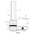
- FIG. 2is a side view of the apparatus of FIG. 1 ;
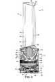
- FIG. 3is a side sectional view of the fan assembly of the apparatus of FIG. 1 ;
- FIG. 4is an enlarged sectional view of part of the nozzle of the fan assembly of the apparatus of FIG. 1 ;
- FIG. 5is a top view of the humidifier of the apparatus of FIG. 1 ;
- FIG. 6is a side sectional view of the humidifier, taken along line D-D in FIG. 5 ;
- FIG. 7is a top view of the base of the humidifier of FIG. 5 ;
- FIG. 8is a top sectional view of the base of the humidifier, taken along line E-E in FIG. 6 ;
- FIG. 9is a side sectional view of the base of the humidifier, taken along line J-J in FIG. 7 ;
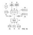
- FIG. 10is a schematic illustration of the control system of the humidifier
- FIG. 11is a graph illustrating the variation with time of the relative humidity detected by the sensor of the humidifying apparatus of FIG. 1 .
- an example of a humidifying apparatuscomprises a fan assembly 10 and a humidifier 100 located behind the fan assembly 10 .
- the fan assembly 10is preferably in the form of a bladeless fan assembly comprising a stand 12 and a nozzle 14 mounted on and supported by the stand 12 .
- the stand 12comprises a substantially cylindrical outer casing 16 having a plurality of air inlets in the form of a grille 18 formed in the outer casing 16 and through which a primary air flow is drawn into the stand 12 from the external environment.
- the stand 12further comprises a plurality of user-operable buttons 20 and a user-operable dial 22 for controlling the operation of the fan assembly 10 .
- the stand 12has a height in the range from 200 to 300 mm
- the outer casing 16has an external diameter in the range from 100 to 200 mm.
- the nozzle 14has an annular shape and defines a central opening 24 .
- the nozzle 14has a height in the range from 200 to 400 mm.
- the nozzle 14comprises a mouth 26 located towards the rear of the fan assembly 10 for emitting air from the fan assembly 10 and through the opening 24 .
- the mouth 26extends at least partially about the opening 24 .
- the inner periphery of the nozzle 14comprises a Coanda surface 28 located adjacent the mouth 26 and over which the mouth 26 directs the air emitted from the fan assembly 10 , a diffuser surface 30 located downstream of the Coanda surface 28 and a guide surface 32 located downstream of the diffuser surface 30 .
- the diffuser surface 30is arranged to taper away from the central axis X of the opening 24 in such a way so as to assist the flow of air emitted from the fan assembly 10 .
- the angle subtended between the diffuser surface 30 and the central axis X of the opening 24is in the range from 5 to 25°, and in this example is around 15°.
- the guide surface 32is arranged at an angle to the diffuser surface 30 to further assist the efficient delivery of a cooling air flow from the fan assembly 10 .
- the guide surface 32is preferably arranged substantially parallel to the central axis X of the opening 24 to present a substantially flat and substantially smooth face to the air flow emitted from the mouth 26 .
- a visually appealing tapered surface 34is located downstream from the guide surface 32 , terminating at a tip surface 36 lying substantially perpendicular to the central axis X of the opening 24 .
- the angle subtended between the tapered surface 34 and the central axis X of the opening 24is preferably around 45°.
- the overall depth of the nozzle 24 in a direction extending along the central axis X of the opening 24is in the range from 100 to 150 mm, and in this example is around 110 mm.
- FIG. 3illustrates a sectional view through the fan assembly 10 .
- the stand 12comprises a base formed from a lower base member 38 and an upper base member 40 mounted on the lower base member 38 , and a main body 42 mounted on the base.
- the lower base member 38has a substantially flat bottom surface 43 .
- the upper base member 40houses a controller 44 for controlling the operation of the fan assembly 10 in response to depression of the user operable buttons 20 shown in FIGS. 1 and 2 , and/or manipulation of the user operable dial 22 .
- the lower base member 38may house an oscillating mechanism 46 for oscillating the upper base member 40 and the main body 42 relative to the lower base member 38 .
- each oscillation cycle of the main body 42is preferably between 60° and 120°, and in this example is around 90°.
- the oscillating mechanism 46is arranged to perform around 3 to 5 oscillation cycles per minute.
- a mains power cable 48extends through an aperture formed in the lower base member 38 for supplying electrical power to the fan assembly 10 .
- the main body 42 of the stand 12has an open upper end to which the nozzle 14 is connected, for example by a snap-fit connection.
- the main body 42houses an impeller 52 for drawing a primary air flow through the apertures of the grille 18 and into the stand 12 .
- the impeller 52is in the form of a mixed flow impeller.
- the impeller 52is connected to a rotary shaft 54 extending outwardly from a motor 56 .
- the motor 56is a DC brushless motor having a speed which is variable by the controller 44 in response to user manipulation of the dial 22 .
- Cable 57connects the controller 44 to the motor 56 .
- the maximum speed of the motor 56is preferably in the range from 5,000 to 10,000 rpm.
- the motor 56is housed within a motor bucket comprising an upper portion 58 connected to a lower portion 60 .
- One of the upper portion 58 and the lower portion 60 of the motor bucketcomprises a diffuser 62 in the form of a stationary disc having spiral blades, and which is located downstream from the impeller 52 .
- the motor bucketis located within, and mounted on, an impeller housing 64 .
- the impeller housing 64is, in turn, mounted on a plurality of angularly spaced supports 66 , in this example three supports, located within the main body 42 of the stand 12 .
- a generally frusto-conical shroud 68is located within the impeller housing 64 .
- the shroud 68is shaped so that the outer edges of the impeller 52 are in close proximity to, but do not contact, the inner surface of the shroud 68 .
- a substantially annular inlet member 70is connected to the bottom of the impeller housing 64 for guiding the primary air flow into the impeller housing 64 .
- the stand 12further comprises silencing foam for reducing noise emissions from the stand 12 .
- the main body 42 of the stand 12comprises a disc-shaped foam member 72 located towards the base of the main body 42 , and a substantially annular foam member 74 located within the motor bucket.
- FIG. 4illustrates a sectional view through the nozzle 14 .
- the nozzle 14comprises an annular outer casing section 80 connected to and extending about an annular inner casing section 82 .
- Each of these sectionsmay be formed from a plurality of connected parts, but in this embodiment each of the outer casing section 80 and the inner casing section 82 is formed from a respective, single moulded part.
- the inner casing section 82defines the central opening 24 of the nozzle 14 , and has an external peripheral surface 84 which is shaped to define the Coanda surface 28 , diffuser surface 30 , guide surface 32 and tapered surface 34 .
- the outer casing section 80 and the inner casing section 82together define an annular interior passage 86 of the nozzle 14 .
- the interior passage 86extends about the opening 24 .
- the interior passage 86is bounded by the internal peripheral surface 88 of the outer casing section 80 and the internal peripheral surface 90 of the inner casing section 82 .
- the outer casing section 80comprises a base 92 which is connected to, and over, the open upper end of the main body 42 of the stand 12 , for example by a snap-fit connection.
- the base 92 of the outer casing section 80comprises an aperture through which the primary air flow enters the interior passage 86 of the nozzle 14 from the open upper end of the main body 42 of the stand 12 .
- the mouth 26 of the nozzle 14is located towards the rear of the fan assembly 10 .
- the mouth 26is defined by overlapping, or facing, portions 94 , 96 of the internal peripheral surface 88 of the outer casing section 80 and the external peripheral surface 84 of the inner casing section 82 , respectively.
- the mouth 26is substantially annular and, as illustrated in FIG. 4 , has a substantially U-shaped cross-section when sectioned along a line passing diametrically through the nozzle 14 .
- the overlapping portions 94 , 96 of the internal peripheral surface 88 of the outer casing section 80 and the external peripheral surface 84 of the inner casing section 82are shaped so that the mouth 26 tapers towards an outlet 98 arranged to direct the primary flow over the Coanda surface 28 .
- the outlet 98is in the form of an annular slot, preferably having a relatively constant width in the range from 0.5 to 5 mm. In this example the outlet 98 has a width of around 1.0 mm.
- Spacersmay be spaced about the mouth 26 for urging apart the overlapping portions 94 , 96 of the internal peripheral surface 88 of the outer casing section 80 and the external peripheral surface 84 of the inner casing section 82 to maintain the width of the outlet 98 at the desired level.
- These spacersmay be integral with either the internal peripheral surface 88 of the outer casing section 80 or the external peripheral surface 84 of the inner casing section 82 .
- the humidifier 100comprises a base 102 and a water tank 104 removably mountable on the base 102 .
- the water tank 104preferably has a capacity in the range from 2 to 4 liters.
- the upper surface of the water tank 104is shaped to define a handle 106 to enable a user to lift the water tank 104 from the base 102 using one hand.
- the water tank 104comprises a mist outlet 108 located in the upper surface 110 of the water tank 104 for emitting moist air, or mist, from the humidifier 100 .
- mistis conveyed to the mist outlet 108 from a duct 112 passing upwardly through the water tank 104 , resulting in the emission of mist from the humidifier 100 in a generally vertical direction.
- Baffles 113are located within the duct 112 to inhibit the emission of relatively large water droplets from the humidifier 100 .
- the base 102 and the water tank 104each comprise a concave front section having a radius which is approximately the same size as the radius of the outer casing 16 of the stand 12 of the fan assembly 10 .
- the mist outlet 108can be spaced from the rear surface of the nozzle 14 of the fan assembly 10 by a minimum distance in the range from 5 to 30 cm.
- the mist outlet 108is preferably located directly behind, and approximately level with, the lowest portion of the Coanda surface 28 of the nozzle 14 of the fan assembly 10 .
- the humidifier 100may be mounted on a support (not shown) to raise the mist outlet 108 so that it is level with the lowest portion of the Coanda surface 28 of the nozzle 14 .
- the water tank 104has a lower surface 114 to which a spout 116 is removably connected, for example through co-operating threaded connections.
- the water tank 104is filled by removing the water tank 104 from the base 102 and inverting the water tank 104 so that the spout 116 is projecting upwardly.
- the spout 116is then unscrewed from the lower surface 114 of the water tank 104 and water is introduced into the water tank 104 through an aperture exposed when the spout 116 is disconnected from the lower surface 114 of the water tank 104 .
- a spring-loaded valve 118is located within the spout 116 for preventing leakage of water through a water outlet 120 of the spout 116 when the water tank 104 is re-inverted.
- the valve 118is biased towards a position in which a skirt 122 of the valve 118 engages the upper surface of the spout 116 to prevent water entering a water inlet 124 of the spout 116 from the water tank 104 .
- a water softener cartridge 126is removably connected to the spout 116 , for example through co-operating threaded connections.
- the cartridge 126may contain an ion-exchange resin, threshold inhibitor chemical, such as polyphosphate, or other media to affect the precipitation of limescale.
- the cartridge 126defines a serpentine path, illustrated at P in FIG. 6 , along which water flows as it passes from the water tank 104 to the spout 116 to increase the residence time of the water within the cartridge 126 . Perforations may be formed on the upper surface of the cartridge 126 to allow air within the cartridge 126 to be displaced therefrom as water enters the cartridge 126 from the water tank 104 .
- the base 102has an upper surface 128 .
- the upper surface 128 of the base 102comprises a recessed portion 130 which defines a water reservoir 132 for receiving water from the water tank 104 .
- a pin 134extending upwardly from the recessed portion 130 of the upper surface 128 protrudes into the spout 116 when the water tank 104 is located on the base 102 .
- the pin 134pushes the valve 118 upwardly to open the spout 116 , thereby allowing water to pass under gravity into the water reservoir 132 from the water tank 104 .
- a magnetic level sensor 136is located within the water reservoir 132 for detecting the level of water within the water reservoir 132 .
- the recessed portion 130 of the upper surface 128comprises two apertures 138 each for exposing the surface of a respective piezoelectric transducer 140 a , 140 b located beneath the upper surface 128 of the base 102 for atomising water stored in the water reservoir 132 .
- An annular metallic heat sink 142is located between the base 102 and each transducer 140 a , 140 b for transferring heat from the transducer to the water stored in the water reservoir 132 .
- Each heat sink 142has a conical upper surface 144 for increasing the rate of atomisation of water by the transducers 140 a , 140 b .
- the atomisation rateis further increased by inclining the upper surfaces of the transducers 140 a , 140 b at an angle in the range from 5 to 10° to the horizontal.
- An annular sealing member 144forms a water-tight seal between each transducer 140 a , 140 b and its heat sink 142 .
- a drive circuit 146is located beneath the upper surface 128 of the base 102 for actuating ultrasonic vibration of the transducers 140 a , 140 b to atomise water within the water reservoir 132 .
- the drive circuit 146may be arranged to receive a signal from the level sensor 136 which is indicative of the level of the water in the water reservoir 132 falling below a minimum level. In response to this signal, the drive circuit 146 terminates actuation of the transducers 140 a , 140 b.
- the base 102further comprises a motor-driven fan 148 for generating an air flow through the humidifier 100 , preferably at a rate in the range from 1 to 2 liters per second.
- the drive circuit 146preferably controls the actuation and the speed of the motor 149 for driving the fan 148 .
- the fan 148is located within a fan housing 150 formed in the base 102 of the humidifier 100 .
- the fan housing 150comprises an air inlet in the form of a plurality of apertures 152 formed in the side wall of the base 102 and through which an air flow is drawn into the fan housing 150 by rotation of the fan 148 , and an air outlet 154 through which the air flow passes into an air duct 156 located to one side of the water reservoir 132 .
- Apertures 158are located on the upper periphery of the air duct 156 for emitting the air flow from the air duct at a level which is above the maximum level for water stored in the water reservoir 132 so that the air flow emitted from the air duct 156 passes over the surface of the water located in the water reservoir 132 before entering the duct 112 of the water tank 102 .
- a user interface for controlling the operation of the humidifier 100is located on the side wall of the base 102 .
- the user interfacecomprises a plurality of user-operable buttons 160 a , 160 b and a user-operable dial 162 .
- the dial 162may be manipulated by the user to set a desired level for the relative humidity of the environment in which the humidifying apparatus is located, such as a room, office or other domestic environment.
- the desired relative humidity levelmay be selected within a range from 30 to 80% at 20° C. through manipulation of the dial 162 .
- buttons 160 ais an on/off button for the humidifier 100
- the other button 160 bmay be depressed to override the dial setting so that the humidifier 100 continues to operate until the water tank 102 has emptied.
- the user interfacefurther comprises a user interface circuit 164 which outputs control signals to the drive circuit 146 which are indicative of the angular position of the dial 162 and upon depression of one of the buttons 160 , and which receives control signals output by the drive circuit 146 .
- the user interfacemay also comprise one or more LEDs (shown in FIG. 10 ) for providing a visual alert depending on a status of the humidifier 100 .
- an LED 165 amay be illuminated by the drive circuit 146 indicating that the water tank 104 has become depleted, as indicated by a signal received by the drive circuit 146 from the level sensor 136 .
- the humidifier 100further comprises a humidity sensor 166 for detecting the relative humidity of air in the external environment, and for supplying a signal indicative of the detected relative humidity to the drive circuit 146 .
- the humidity sensor 166is located immediately behind the apertures 152 formed in the side wall of the base 102 to detect the relative humidity of the air flow drawn into the base 104 of the humidifier 100 by the fan 148 .
- the user interfacemay comprise an LED 165 b which is illuminated by the drive circuit 146 when an output from the humidity sensor 166 indicates that the relative humidity of the air flow entering the base 102 is at or above the desired relative humidity level set by the user.
- the humidifier 100also comprises a power supply 168 for supplying power to the various electrical components of the humidifier 100 , including the drive circuit 146 , the motor for driving the fan 148 and the user interface circuit 164 .
- a mains power cable(not shown) extends through an aperture formed in the base 102 for supplying electrical power to the power supply 168 .
- the userdepresses an appropriate one of the buttons 20 on the stand 12 of the fan assembly 10 , in response to which the controller 44 activates the motor 56 to rotate the impeller 52 .
- the rotation of the impeller 52causes a primary air flow to be drawn into the stand 12 of the fan assembly 10 through the grille 18 .
- the primary air flowpasses sequentially through the impeller housing 64 and the aperture formed in the base 92 of the outer casing section 80 of the nozzle 14 to enter the interior passage 86 of the nozzle 14 .
- the primary air flowis divided into two air streams which pass in opposite directions around the central opening 24 of the nozzle 14 . As the air streams pass through the interior passage 86 , air enters the mouth 26 of the nozzle 14 .
- the air flow into the mouth 26is preferably substantially even about the opening 24 of the nozzle 14 .
- the flow direction of the portion of the air streamis substantially reversed.
- the portion of the air streamis constricted by the tapering section of the mouth 26 and emitted through the outlet 98 .
- the primary air flow emitted from the mouth 26is directed over the Coanda surface 28 of the nozzle 14 , causing a secondary air flow to be generated by the entrainment of air from the external environment, specifically from the region around the outlet 98 of the mouth 26 and from around the rear of the nozzle 14 .
- This secondary air flowpasses through the central opening 24 of the nozzle 14 , where it combines with the primary air flow to produce a total air flow, or air current, projected forward from the nozzle 14 .
- the mass flow rate of the air current projected forward from the fan assembly 10may be up to 400 liters per second, preferably up to 600 liters per second.
- the even distribution of the primary air flow along the mouth 26 of the nozzle 14ensures that the air flow passes evenly over the diffuser surface 30 .
- the diffuser surface 30causes the mean speed of the air flow to be reduced by moving the air flow through a region of controlled expansion.
- the relatively shallow angle of the diffuser surface 30 to the central axis X of the opening 24allows the expansion of the air flow to occur gradually.
- a harsh or rapid divergencewould otherwise cause the air flow to become disrupted, generating vortices in the expansion region.
- Such vorticescan lead to an increase in turbulence and associated noise in the air flow which can be undesirable, particularly in a domestic product such as a fan.
- the air flow projected forwards beyond the diffuser surface 30can tend to continue to diverge.
- the presence of the guide surface 32 extending substantially parallel to the central axis X of the opening 30further converges the air flow. As a result, the air flow can travel efficiently out from the nozzle 14 , enabling the air flow can be experienced rapidly at a distance of several meters from the fan assembly 10 .
- the usermay switch on the humidifier 100 by pressing the appropriate button 160 a of the user interface of the humidifier 100 .
- the drive circuit 146activates the motor 149 to rotate the fan 148 to generate an air flow through the humidifier 100 .
- the drive circuit 146actuates the vibration of both of the transducers 140 a , 140 b , preferably at a frequency in the range from 1 to 2 MHz, to atomise water present within the water reservoir 132 .
- the water reservoir 132is constantly replenished with water from the water tank 104 , so that the level of water within the water reservoir 132 remains substantially constant while the level of water within the water tank 104 gradually falls.
- an air flowis drawn into the humidifier 100 through the apertures 152 formed in the side wall of the base 102 .
- the air flowpasses through the fan housing 150 and into the air duct 156 , from which it is emitted through the apertures 158 .
- the air flowpasses over the water located in the water reservoir 132 , causing the airborne water droplets to become entrained within the air flow generated by the fan 148 .
- The—now moist—air flowpasses upwardly through the spout 112 and is emitted from the mist outlet 108 in the form of a mist or fog.
- This mistis drawn through the central opening 24 of the nozzle 14 as part of the secondary air flow generated by the emission of the primary air flow from the mouth 26 of the nozzle 14 . Consequently, the mist is conveyed away from the humidifier 100 within the air current generated by the fan assembly 10 , thereby enabling a humid air current to be experienced rapidly at a distance of several meters from the humidifier 100 .
- this humid air currentcan be swept over an arc in the range from 60 to 120°, preferably around 90°, to increase rapidly the dispersion of the humid air into the external environment.
- the moist air flowis emitted from the humidifier 100 until the relative humidity of the air flow entering the humidifier 100 , as detected by the humidity sensor 166 , is 1% at 20° C. higher than the relative humidity level selected by the user using the dial 162 .
- the emission of a moist air flow from the humidifier 100is then terminated by the drive circuit 146 , through terminating the supply of actuating signals to the transducers 140 a , 140 b .
- the motor 149may also be stopped so that no air flow is emitted from the humidifier 100 but when the humidity sensor 166 is located in close proximity to the motor 149 , as in this example, it is preferred that the motor 149 is continually operated to avoid undesirable temperature fluctuation in the local environment of the humidity sensor 166 .
- the motor 149may also be stopped when the relative humidity of the air of the environment local to the humidity sensor 166 is 1% at 20° C. higher than the relative humidity level selected by the user.
- the relative humidity detected by the humidity sensor 166will begin to fall.
- the drive circuit 146outputs actuating signals to a selected one of the transducers, for example transducer 140 a , to re-start the emission of a moist air flow from the humidifier 100 .
- the moist air flowis emitted from the humidifier 100 until the relative humidity detected by the humidity sensor 166 is 1% at 20° C.
- the drive circuit 146outputs actuating signals to the other transducer, for example transducer 140 b , to re-start the emission of a moist air flow from the humidifier 100 .
- the moist air flowis emitted from the humidifier 100 until the relative humidity detected by the humidity sensor 166 is 1% at 20° C. higher than the relative humidity level selected by the user, at which point the actuation of the transducer 140 b is terminated.
- This sequence of alternate actuation of the transducers 140 a , 140 b to maintain the detected humidity level around the level selected by the usercontinues until the button 160 a is depressed to switch off the humidifier 100 or until a signal is received from the level sensor 136 indicating that the level of water within the water reservoir 132 has fallen by the minimum level.
- the relative humidity detected by the humidity sensor 166is thus maintained around the level selected by the user using the dial 162 by the subsequent actuation of a reduced number n 2 of transducers (one) in comparison to the number n 1 of transducers (two) used to initially increase the relative humidity in the external environment to the selected level.
- the advantage associated with the actuation of a greater number of transducers to initially raise the relative humidity in the external environment to the selected levelis indicated in FIG. 11 .
- FIG. 11is a graph illustrating the variation of the detected relative humidity with time for two operations of the humidifying apparatus. In the first operation both transducers 140 a , 140 b are actuated initially to raise the relative humidity to 50% at 20° C.
- transducer 140 aIn the second operation, only transducer 140 a is actuated to initially raise the relative humidity to 50% at 20° C.
- the variation of the detected relative humidity with time for the first operationis indicated by line 180 in FIG. 11
- the variation of the detected relative humidity with time for the second operationis indicated by line 182 in FIG. 11 .
- the time taken for the detected relative humidity to increase from a base level of around 30% at 20° C. to the preset levelwas considerably shorter when both transducers 140 a , 140 b were used to raise the relative humidity to 50% at 20° C.
- the same number n 1 of transducers (two) used to initially increase the relative humidity in the external environment to the selected levelmay also be used to maintain the detected relative humidity around the preset level.
- the duration of the actuation of the n 1 transducers from when the detected relative humidity of the air of the environment local to the humidity sensor 166 has again fallen to 1% at 20° C. below the relative humidity level to when the relative humidity detected by the humidity sensor 166 is 1% at 20° C. higher than the relative humidity level selected by the useris shorter than when the reduced number n 2 of transducers to maintain the detected relative humidity around the preset level.
- both transducers 140 a , 140 bare actuated to maintain the detected relative humidity around the preset level, whereas in the second operation only a single actuator is used to maintain the detected relative humidity around the preset level. Similar to when a reduced number n 2 of transducers is used to maintain the detected relative humidity around the preset level, this can enable the life time of the transducers 140 a , 140 b to be prolonged.
Landscapes
- Engineering & Computer Science (AREA)
- Mechanical Engineering (AREA)
- General Engineering & Computer Science (AREA)
- Chemical & Material Sciences (AREA)
- Combustion & Propulsion (AREA)
- Dispersion Chemistry (AREA)
- Physics & Mathematics (AREA)
- Fluid Mechanics (AREA)
- Air Humidification (AREA)
- Air Conditioning Control Device (AREA)
- Structures Of Non-Positive Displacement Pumps (AREA)
Abstract
Description
Claims (28)
Priority Applications (1)
| Application Number | Priority Date | Filing Date | Title |
|---|---|---|---|
| US13/718,693US8783663B2 (en) | 2009-03-04 | 2012-12-18 | Humidifying apparatus |
Applications Claiming Priority (6)
| Application Number | Priority Date | Filing Date | Title |
|---|---|---|---|
| GB0903690.6 | 2009-03-04 | ||
| GB0903690AGB2468328A (en) | 2009-03-04 | 2009-03-04 | Fan assembly with humidifier |
| GB0915033AGB2473037A (en) | 2009-08-28 | 2009-08-28 | Humidifying apparatus comprising a fan and a humidifier with a plurality of transducers |
| GB0915033.5 | 2009-08-28 | ||
| US12/716,707US8356804B2 (en) | 2009-03-04 | 2010-03-03 | Humidifying apparatus |
| US13/718,693US8783663B2 (en) | 2009-03-04 | 2012-12-18 | Humidifying apparatus |
Related Parent Applications (1)
| Application Number | Title | Priority Date | Filing Date |
|---|---|---|---|
| US12/716,707ContinuationUS8356804B2 (en) | 2009-03-04 | 2010-03-03 | Humidifying apparatus |
Publications (2)
| Publication Number | Publication Date |
|---|---|
| US20130161842A1 US20130161842A1 (en) | 2013-06-27 |
| US8783663B2true US8783663B2 (en) | 2014-07-22 |
Family
ID=42342606
Family Applications (2)
| Application Number | Title | Priority Date | Filing Date |
|---|---|---|---|
| US12/716,707Expired - Fee RelatedUS8356804B2 (en) | 2009-03-04 | 2010-03-03 | Humidifying apparatus |
| US13/718,693Expired - Fee RelatedUS8783663B2 (en) | 2009-03-04 | 2012-12-18 | Humidifying apparatus |
Family Applications Before (1)
| Application Number | Title | Priority Date | Filing Date |
|---|---|---|---|
| US12/716,707Expired - Fee RelatedUS8356804B2 (en) | 2009-03-04 | 2010-03-03 | Humidifying apparatus |
Country Status (10)
| Country | Link |
|---|---|
| US (2) | US8356804B2 (en) |
| EP (1) | EP2414738B1 (en) |
| JP (2) | JP5260582B2 (en) |
| KR (1) | KR101290625B1 (en) |
| CN (2) | CN202056982U (en) |
| AU (2) | AU2010220190B2 (en) |
| CA (1) | CA2746560C (en) |
| ES (1) | ES2437740T3 (en) |
| RU (1) | RU2511503C2 (en) |
| WO (1) | WO2010100462A1 (en) |
Cited By (36)
| Publication number | Priority date | Publication date | Assignee | Title |
|---|---|---|---|---|
| USD728092S1 (en) | 2013-08-01 | 2015-04-28 | Dyson Technology Limited | Fan |
| USD728769S1 (en) | 2013-08-01 | 2015-05-05 | Dyson Technology Limited | Fan |
| USD728770S1 (en) | 2013-08-01 | 2015-05-05 | Dyson Technology Limited | Fan |
| USD729372S1 (en) | 2013-03-07 | 2015-05-12 | Dyson Technology Limited | Fan |
| USD729376S1 (en) | 2013-03-07 | 2015-05-12 | Dyson Technology Limited | Fan |
| USD729374S1 (en)* | 2013-03-07 | 2015-05-12 | Dyson Technology Limited | Fan |
| USD729375S1 (en)* | 2013-03-07 | 2015-05-12 | Dyson Technology Limited | Fan |
| USD729373S1 (en)* | 2013-03-07 | 2015-05-12 | Dyson Technology Limited | Fan |
| USD729925S1 (en) | 2013-03-07 | 2015-05-19 | Dyson Technology Limited | Fan |
| USD746425S1 (en) | 2013-01-18 | 2015-12-29 | Dyson Technology Limited | Humidifier |
| USD746966S1 (en) | 2013-01-18 | 2016-01-05 | Dyson Technology Limited | Humidifier |
| USD747450S1 (en) | 2013-01-18 | 2016-01-12 | Dyson Technology Limited | Humidifier |
| USD749231S1 (en) | 2013-01-18 | 2016-02-09 | Dyson Technology Limited | Humidifier |
| US9366449B2 (en) | 2012-03-06 | 2016-06-14 | Dyson Technology Limited | Humidifying apparatus |
| US9410711B2 (en) | 2013-09-26 | 2016-08-09 | Dyson Technology Limited | Fan assembly |
| USD768281S1 (en)* | 2015-01-30 | 2016-10-04 | Dyson Technology Limited | Fan |
| USD768280S1 (en)* | 2015-01-30 | 2016-10-04 | Dyson Technology Limited | Fan |
| USD768840S1 (en)* | 2015-01-30 | 2016-10-11 | Dyson Technology Limited | Fan |
| USD768841S1 (en)* | 2015-01-30 | 2016-10-11 | Dyson Technology Limited | Fan |
| USD768839S1 (en)* | 2015-01-30 | 2016-10-11 | Dyson Technology Limited | Fan |
| US9599356B2 (en) | 2014-07-29 | 2017-03-21 | Dyson Technology Limited | Humidifying apparatus |
| US9745981B2 (en) | 2011-11-11 | 2017-08-29 | Dyson Technology Limited | Fan assembly |
| US9752789B2 (en) | 2012-03-06 | 2017-09-05 | Dyson Technology Limited | Humidifying apparatus |
| US9797613B2 (en) | 2012-03-06 | 2017-10-24 | Dyson Technology Limited | Humidifying apparatus |
| US9797612B2 (en) | 2013-01-29 | 2017-10-24 | Dyson Technology Limited | Fan assembly |
| USD804007S1 (en)* | 2015-11-25 | 2017-11-28 | Vornado Air Llc | Air circulator |
| US9903602B2 (en) | 2014-07-29 | 2018-02-27 | Dyson Technology Limited | Humidifying apparatus |
| US9927136B2 (en) | 2012-03-06 | 2018-03-27 | Dyson Technology Limited | Fan assembly |
| US9982677B2 (en) | 2014-07-29 | 2018-05-29 | Dyson Technology Limited | Fan assembly |
| US10408478B2 (en) | 2012-03-06 | 2019-09-10 | Dyson Technology Limited | Humidifying apparatus |
| US10465928B2 (en) | 2012-03-06 | 2019-11-05 | Dyson Technology Limited | Humidifying apparatus |
| US10612565B2 (en) | 2013-01-29 | 2020-04-07 | Dyson Technology Limited | Fan assembly |
| US10926210B2 (en) | 2018-04-04 | 2021-02-23 | ACCO Brands Corporation | Air purifier with dual exit paths |
| USD913467S1 (en) | 2018-06-12 | 2021-03-16 | ACCO Brands Corporation | Air purifier |
| US11384956B2 (en) | 2017-05-22 | 2022-07-12 | Sharkninja Operating Llc | Modular fan assembly with articulating nozzle |
| USD1079922S1 (en) | 2022-11-30 | 2025-06-17 | Vornado Air, Llc | Tower fan |
Families Citing this family (133)
| Publication number | Priority date | Publication date | Assignee | Title |
|---|---|---|---|---|
| GB0814835D0 (en) | 2007-09-04 | 2008-09-17 | Dyson Technology Ltd | A Fan |
| GB2463698B (en) | 2008-09-23 | 2010-12-01 | Dyson Technology Ltd | A fan |
| GB2464736A (en) | 2008-10-25 | 2010-04-28 | Dyson Technology Ltd | Fan with a filter |
| GB2466058B (en)* | 2008-12-11 | 2010-12-22 | Dyson Technology Ltd | Fan nozzle with spacers |
| GB0903682D0 (en) | 2009-03-04 | 2009-04-15 | Dyson Technology Ltd | A fan |
| PL2276933T3 (en) | 2009-03-04 | 2011-10-31 | Dyson Technology Ltd | A fan |
| GB2468317A (en) | 2009-03-04 | 2010-09-08 | Dyson Technology Ltd | Height adjustable and oscillating fan |
| GB2468325A (en)* | 2009-03-04 | 2010-09-08 | Dyson Technology Ltd | Height adjustable fan with nozzle |
| KR101395177B1 (en) | 2009-03-04 | 2014-05-15 | 다이슨 테크놀러지 리미티드 | A fan |
| GB2468315A (en) | 2009-03-04 | 2010-09-08 | Dyson Technology Ltd | Tilting fan |
| GB2468322B (en) | 2009-03-04 | 2011-03-16 | Dyson Technology Ltd | Tilting fan stand |
| GB2468326A (en) | 2009-03-04 | 2010-09-08 | Dyson Technology Ltd | Telescopic pedestal fan |
| CN202056982U (en) | 2009-03-04 | 2011-11-30 | 戴森技术有限公司 | Humidifying device |
| GB2468323A (en) | 2009-03-04 | 2010-09-08 | Dyson Technology Ltd | Fan assembly |
| NZ593318A (en) | 2009-03-04 | 2012-11-30 | Dyson Technology Ltd | An annular fan assembly with a silencing member |
| GB2468312A (en) | 2009-03-04 | 2010-09-08 | Dyson Technology Ltd | Fan assembly |
| GB2468331B (en) | 2009-03-04 | 2011-02-16 | Dyson Technology Ltd | A fan |
| GB2468329A (en) | 2009-03-04 | 2010-09-08 | Dyson Technology Ltd | Fan assembly |
| GB2468320C (en) | 2009-03-04 | 2011-06-01 | Dyson Technology Ltd | Tilting fan |
| GB0919473D0 (en) | 2009-11-06 | 2009-12-23 | Dyson Technology Ltd | A fan |
| GB2478927B (en) | 2010-03-23 | 2016-09-14 | Dyson Technology Ltd | Portable fan with filter unit |
| GB2478925A (en) | 2010-03-23 | 2011-09-28 | Dyson Technology Ltd | External filter for a fan |
| SG186071A1 (en) | 2010-05-27 | 2013-01-30 | Dyson Technology Ltd | Device for blowing air by means of narrow slit nozzle assembly |
| GB2482549A (en) | 2010-08-06 | 2012-02-08 | Dyson Technology Ltd | A fan assembly with a heater |
| GB2482548A (en) | 2010-08-06 | 2012-02-08 | Dyson Technology Ltd | A fan assembly with a heater |
| GB2482547A (en) | 2010-08-06 | 2012-02-08 | Dyson Technology Ltd | A fan assembly with a heater |
| GB2483448B (en) | 2010-09-07 | 2015-12-02 | Dyson Technology Ltd | A fan |
| JP5588565B2 (en) | 2010-10-13 | 2014-09-10 | ダイソン テクノロジー リミテッド | Blower assembly |
| EP2630373B1 (en) | 2010-10-18 | 2016-12-28 | Dyson Technology Limited | A fan assembly |
| GB2484670B (en) | 2010-10-18 | 2018-04-25 | Dyson Technology Ltd | A fan assembly |
| JP5778293B2 (en) | 2010-11-02 | 2015-09-16 | ダイソン テクノロジー リミテッド | Blower assembly |
| GB2486019B (en) | 2010-12-02 | 2013-02-20 | Dyson Technology Ltd | A fan |
| GB2486892B (en) | 2010-12-23 | 2017-11-15 | Dyson Technology Ltd | A fan |
| GB2486889B (en) | 2010-12-23 | 2017-09-06 | Dyson Technology Ltd | A fan |
| GB2486890B (en) | 2010-12-23 | 2017-09-06 | Dyson Technology Ltd | A fan |
| TWD146515S (en)* | 2011-04-22 | 2012-04-11 | 蓋博企業有限公司 | Bladeless fan |
| CN102865257A (en)* | 2011-07-06 | 2013-01-09 | 任文华 | Vaneless fan |
| CN102269459A (en)* | 2011-07-13 | 2011-12-07 | 上海腾邦环境科技有限公司 | Movable spraying unit |
| GB2492961A (en) | 2011-07-15 | 2013-01-23 | Dyson Technology Ltd | Fan with impeller and motor inside annular casing |
| GB2492962A (en) | 2011-07-15 | 2013-01-23 | Dyson Technology Ltd | Fan with tangential inlet to casing passage |
| GB2492963A (en)* | 2011-07-15 | 2013-01-23 | Dyson Technology Ltd | Fan with scroll casing decreasing in cross-section |
| US20130019619A1 (en)* | 2011-07-22 | 2013-01-24 | Atico International Usa, Inc. | Bladeless misting fan |
| GB2493506B (en)* | 2011-07-27 | 2013-09-11 | Dyson Technology Ltd | A fan assembly |
| BR112014001474A2 (en)* | 2011-07-27 | 2017-02-21 | Dyson Technology Ltd | fan assembly |
| AU2012216659B2 (en) | 2011-09-13 | 2016-03-24 | Black & Decker Inc | Air ducting shroud for cooling an air compressor pump and motor |
| US8899378B2 (en) | 2011-09-13 | 2014-12-02 | Black & Decker Inc. | Compressor intake muffler and filter |
| CN102338133A (en)* | 2011-09-30 | 2012-02-01 | 东莞市旭尔美电器科技有限公司 | A bladeless fan |
| GB2496877B (en) | 2011-11-24 | 2014-05-07 | Dyson Technology Ltd | A fan assembly |
| CN102661268A (en)* | 2011-12-29 | 2012-09-12 | 乐清市畅想电器科技有限公司 | Novel non-leaf humidifying fan and method of humidifying |
| FR2985202A1 (en)* | 2012-01-03 | 2013-07-05 | Oreal | HEAD OF DISTRIBUTION |
| FR2985201B1 (en)* | 2012-01-03 | 2016-01-08 | Oreal | HOLLOW DISTRIBUTION HEAD |
| USD678993S1 (en)* | 2012-01-06 | 2013-03-26 | Cute Item Industries, Ltd. | Bladeless hand held fan |
| USD676536S1 (en)* | 2012-01-19 | 2013-02-19 | Atico International Usa, Inc. | Bladeless misting fan |
| GB2498547B (en) | 2012-01-19 | 2015-02-18 | Dyson Technology Ltd | A fan |
| GB2499042A (en) | 2012-02-06 | 2013-08-07 | Dyson Technology Ltd | A nozzle for a fan assembly |
| GB2499044B (en) | 2012-02-06 | 2014-03-19 | Dyson Technology Ltd | A fan |
| GB2499041A (en) | 2012-02-06 | 2013-08-07 | Dyson Technology Ltd | Bladeless fan including an ionizer |
| KR102046476B1 (en)* | 2012-02-29 | 2019-11-19 | 웅진코웨이 주식회사 | Humidification apparatus capable of preventing water leak |
| GB2500009B (en)* | 2012-03-06 | 2015-08-05 | Dyson Technology Ltd | A Humidifying Apparatus |
| GB2500903B (en) | 2012-04-04 | 2015-06-24 | Dyson Technology Ltd | Heating apparatus |
| GB2501301B (en) | 2012-04-19 | 2016-02-03 | Dyson Technology Ltd | A fan assembly |
| GB2518935B (en) | 2012-05-16 | 2016-01-27 | Dyson Technology Ltd | A fan |
| EP2850324A2 (en) | 2012-05-16 | 2015-03-25 | Dyson Technology Limited | A fan |
| GB2532557B (en) | 2012-05-16 | 2017-01-11 | Dyson Technology Ltd | A fan comprsing means for suppressing noise |
| JP2013242072A (en)* | 2012-05-18 | 2013-12-05 | Iris Ohyama Inc | Humidifying mechanism |
| US20130320574A1 (en)* | 2012-05-18 | 2013-12-05 | The Yankee Candle Company, Inc. | Aerodynamic formula dispersing apparatus |
| JP5849869B2 (en)* | 2012-06-26 | 2016-02-03 | 株式会社デンソー | Blower |
| GB2503907B (en) | 2012-07-11 | 2014-05-28 | Dyson Technology Ltd | A fan assembly |
| CN103629086A (en)* | 2012-08-21 | 2014-03-12 | 任文华 | Fan |
| FR2999100B1 (en)* | 2012-12-06 | 2015-01-16 | Seb Sa | REFRESHING DEVICE |
| FR3007953B1 (en) | 2013-07-04 | 2015-07-24 | Oreal | AEROSOL ALCOHOLIC DEODORANT EQUIPPED WITH A HOLLOW DISTRIBUTION HEAD |
| FR3007952B1 (en)* | 2013-07-04 | 2015-07-24 | Oreal | AEROSOL CONTAINING AN EMULSION DEODORANT EQUIPPED WITH A HOLLOW DISTRIBUTION HEAD |
| GB2516058B (en) | 2013-07-09 | 2016-12-21 | Dyson Technology Ltd | A fan assembly with an oscillation and tilt mechanism |
| CN103410768B (en)* | 2013-08-28 | 2016-08-31 | 黄俊龙 | Safety Fan |
| CN106286398A (en)* | 2013-08-28 | 2017-01-04 | 乐清市华尊电气有限公司 | A kind of electricity cold mould electric fan |
| CN106337823A (en)* | 2013-08-28 | 2017-01-18 | 乐清市华尊电气有限公司 | Safe electric fan capable of refrigerating |
| CN105715566A (en)* | 2013-08-28 | 2016-06-29 | 胡妍 | Blade-free double-head fan |
| CN105927514B (en)* | 2013-08-28 | 2019-03-26 | 乐清市芮易经济信息咨询有限公司 | A kind of bladeless fan |
| KR101702169B1 (en) | 2013-10-02 | 2017-02-02 | 엘지전자 주식회사 | Indoor unit for cassette type air conditoiner |
| KR101706812B1 (en) | 2013-10-02 | 2017-02-14 | 엘지전자 주식회사 | Indoor unit for cassette type air conditoiner |
| KR20150043573A (en)* | 2013-10-11 | 2015-04-23 | 엘지전자 주식회사 | Indoor unit for cassette type air conditoiner |
| JP1518058S (en) | 2014-01-09 | 2015-02-23 | ||
| JP1518059S (en) | 2014-01-09 | 2015-02-23 | ||
| KR101662377B1 (en) | 2014-01-27 | 2016-10-04 | 엘지전자 주식회사 | Indoor unit of air conditoiner |
| US9316405B2 (en)* | 2014-07-10 | 2016-04-19 | Dana Electronics Co., Ltd. | Cyclone type humidifier and wet air purifier combination device using centrifugal force |
| JP6272188B2 (en)* | 2014-08-29 | 2018-01-31 | アイリスオーヤマ株式会社 | Ultrasonic humidifier |
| US9855522B2 (en)* | 2014-10-24 | 2018-01-02 | Lg Electronics Inc. | Air purifier |
| EP3056827A1 (en)* | 2014-11-27 | 2016-08-17 | OC S.r.l. | Ventilation system for a micronizer, in particular for washing machines-sterilizers |
| DE102014017774B4 (en)* | 2014-12-02 | 2018-05-17 | Audi Ag | Method for ventilation of a room and ventilation system |
| USD753280S1 (en)* | 2014-12-19 | 2016-04-05 | Auramist, Inc. | Fan |
| USD747451S1 (en)* | 2014-12-19 | 2016-01-12 | Auramist, Inc. | Fan |
| TWD179707S (en)* | 2015-01-30 | 2016-11-21 | 戴森科技有限公司 | A fan |
| KR20170024313A (en) | 2015-08-25 | 2017-03-07 | 신재옥 | Apparatus for humid air injection |
| CN106524343A (en)* | 2015-09-15 | 2017-03-22 | 戴赐鹏 | Cleaning system and method for controlling indoor harmful substances |
| US11111913B2 (en) | 2015-10-07 | 2021-09-07 | Black & Decker Inc. | Oil lubricated compressor |
| CN105179999A (en)* | 2015-10-17 | 2015-12-23 | 李陈 | LED flame lamp |
| DE102016120775B4 (en)* | 2015-11-02 | 2025-02-20 | Cognex Corporation | System and method for detecting lines in an image with a vision system |
| EP3211346B1 (en)* | 2016-02-26 | 2021-10-27 | LG Electronics Inc. | Air cleaner |
| EP3211345B1 (en) | 2016-02-26 | 2020-09-16 | Lg Electronics Inc. | Air cleaner |
| EP3211338B1 (en)* | 2016-02-26 | 2020-03-25 | LG Electronics Inc. | Air cleaner and method for controlling an air cleaner |
| EP3211337B1 (en) | 2016-02-26 | 2020-09-23 | LG Electronics Inc. | Air cleaner |
| EP3211335B1 (en)* | 2016-02-26 | 2020-05-13 | LG Electronics Inc. | Air cleaner |
| US20170246577A1 (en)* | 2016-02-26 | 2017-08-31 | Lg Electronics Inc. | Air cleaner |
| EP3211347B1 (en) | 2016-02-26 | 2020-12-30 | LG Electronics Inc. | Air cleaner |
| US10436469B2 (en) | 2016-02-26 | 2019-10-08 | Lg Electronics Inc. | Air cleaner |
| US9950289B2 (en)* | 2016-02-26 | 2018-04-24 | Lg Electronics Inc. | Air cleaner |
| CN111765554B (en) | 2016-02-26 | 2022-02-25 | Lg电子株式会社 | Air cleaner |
| WO2017146353A1 (en) | 2016-02-26 | 2017-08-31 | 엘지전자 주식회사 | Air purifier |
| CN111156622B (en) | 2016-02-26 | 2022-04-26 | Lg电子株式会社 | Air cleaner |
| CN106051948B (en)* | 2016-07-18 | 2021-07-30 | 中山市兆美电子电器有限公司 | A double fan air purifier |
| US12000621B2 (en)* | 2016-12-07 | 2024-06-04 | Coway Co., Ltd. | Wind-direction adjustable air purifier |
| KR101865226B1 (en)* | 2016-12-12 | 2018-06-08 | (주)에이치더블유엘 | Ultrasonic humidifier |
| CN106704245B (en)* | 2016-12-20 | 2019-07-30 | 美的集团股份有限公司 | Pedestal and bladeless fan |
| CN110770448B (en)* | 2017-05-04 | 2022-04-22 | 曼凯·曼纳查特 | Bladeless fan in fluid tube |
| EP3401023B1 (en) | 2017-05-11 | 2020-07-08 | Boga GmbH Gesellschaft für Moderne Gerätetechnik | Device for the atomization of a liquid |
| CN107228444B (en)* | 2017-06-26 | 2020-10-30 | 广东美的制冷设备有限公司 | Humidifying device and control method thereof |
| CN107388463A (en)* | 2017-08-08 | 2017-11-24 | 佛山市顺德区帼鑫电器实业有限公司 | A kind of easy cleaning humidifier |
| US10920792B2 (en)* | 2018-04-25 | 2021-02-16 | Comefresh Electronic Industry Co., Ltd. | Air circulator |
| GB2575814B (en)* | 2018-07-23 | 2020-12-09 | Dyson Technology Ltd | A wearable air purifier |
| KR102091777B1 (en) | 2018-07-23 | 2020-03-20 | 황부건 | Wet air injection device |
| KR102189875B1 (en) | 2018-12-12 | 2020-12-11 | 주식회사 애드소닉 | Ultrasonic Humidifier |
| EP3674559B1 (en) | 2018-12-24 | 2021-06-02 | LEONARDO S.p.A. | Jet fan and vehicle comprising such a fan |
| USD923767S1 (en)* | 2019-05-02 | 2021-06-29 | Dyson Technology Limited | Humidifier |
| CN110131957B (en)* | 2019-05-17 | 2024-03-29 | 广东奥马冰箱有限公司 | Automatic humidifying device in place |
| CN210801357U (en)* | 2019-07-16 | 2020-06-19 | 广东东方麦田工业设计股份有限公司 | Humidifying warm-air drier |
| CN111577657B (en)* | 2020-04-29 | 2021-10-29 | 南京工业大学 | Compressor Blades with Self-Excited Swept Jet Flow Control |
| CN111594470A (en)* | 2020-05-19 | 2020-08-28 | 凯优奇科技(广东)有限公司 | Bladeless fan |
| USD959631S1 (en)* | 2020-09-30 | 2022-08-02 | Shenzhen Xiluo Technology Co., Ltd | Air purifier |
| USD971878S1 (en)* | 2020-12-29 | 2022-12-06 | Baiqian Zuo | Speaker humidifier |
| CN114190681B (en)* | 2021-01-21 | 2024-02-23 | 杭州乐秀电子科技有限公司 | Hair care hurricane cylinder |
| CN115899906A (en)* | 2022-11-15 | 2023-04-04 | 中山市宏冠西联电气科技有限公司 | Improved control humidifier and floor fan |
| USD1007665S1 (en)* | 2023-07-20 | 2023-12-12 | Xiongjian Chen | Fan |
| CN116713154B (en)* | 2023-08-10 | 2023-10-03 | 广东科高电器有限公司 | Circulation atomizing device |
Citations (365)
| Publication number | Priority date | Publication date | Assignee | Title |
|---|---|---|---|---|
| US284962A (en) | 1883-09-11 | William huston | ||
| US1357261A (en) | 1918-10-02 | 1920-11-02 | Ladimir H Svoboda | Fan |
| US1767060A (en) | 1928-10-04 | 1930-06-24 | W H Addington | Electric motor-driven desk fan |
| GB383498A (en) | 1931-03-03 | 1932-11-17 | Spontan Ab | Improvements in or relating to fans, ventilators, or the like |
| US1896869A (en) | 1931-07-18 | 1933-02-07 | Master Electric Co | Electric fan |
| US2014185A (en) | 1930-06-25 | 1935-09-10 | Martin Brothers Electric Compa | Drier |
| US2035733A (en) | 1935-06-10 | 1936-03-31 | Marathon Electric Mfg | Fan motor mounting |
| US2071266A (en) | 1935-10-31 | 1937-02-16 | Continental Can Co | Lock top metal container |
| US2115883A (en) | 1937-04-21 | 1938-05-03 | Sher Samuel | Lamp |
| US2210458A (en) | 1936-11-16 | 1940-08-06 | Lester S Keilholtz | Method of and apparatus for air conditioning |
| US2258961A (en) | 1939-07-26 | 1941-10-14 | Prat Daniel Corp | Ejector draft control |
| US2295502A (en) | 1941-05-20 | 1942-09-08 | Lamb Edward | Heater |
| US2336295A (en) | 1940-09-25 | 1943-12-07 | Reimuller Caryl | Air diverter |
| US2363839A (en) | 1941-02-05 | 1944-11-28 | Demuth Charles | Unit type air conditioning register |
| GB593828A (en) | 1945-06-14 | 1947-10-27 | Dorothy Barker | Improvements in or relating to propeller fans |
| US2433795A (en) | 1945-08-18 | 1947-12-30 | Westinghouse Electric Corp | Fan |
| GB601222A (en) | 1944-10-04 | 1948-04-30 | Berkeley & Young Ltd | Improvements in, or relating to, electric fans |
| US2473325A (en) | 1946-09-19 | 1949-06-14 | E A Lab Inc | Combined electric fan and air heating means |
| US2476002A (en) | 1946-01-12 | 1949-07-12 | Edward A Stalker | Rotating wing |
| US2488467A (en) | 1947-09-12 | 1949-11-15 | Lisio Salvatore De | Motor-driven fan |
| GB633273A (en) | 1948-02-12 | 1949-12-12 | Albert Richard Ponting | Improvements in or relating to air circulating apparatus |
| US2510132A (en) | 1948-05-27 | 1950-06-06 | Morrison Hackley | Oscillating fan |
| GB641622A (en) | 1942-05-06 | 1950-08-16 | Fernan Oscar Conill | Improvements in or relating to hair drying |
| US2544379A (en) | 1946-11-15 | 1951-03-06 | Oscar J Davenport | Ventilating apparatus |
| US2547448A (en) | 1946-02-20 | 1951-04-03 | Demuth Charles | Hot-air space heater |
| GB661747A (en) | 1948-12-18 | 1951-11-28 | British Thomson Houston Co Ltd | Improvements in and relating to oscillating fans |
| US2583374A (en) | 1950-10-18 | 1952-01-22 | Hydraulic Supply Mfg Company | Exhaust fan |
| US2620127A (en) | 1950-02-28 | 1952-12-02 | Westinghouse Electric Corp | Air translating apparatus |
| FR1033034A (en) | 1951-02-23 | 1953-07-07 | Articulated stabilizer support for fan with flexible propellers and variable speeds | |
| FR1119439A (en) | 1955-02-18 | 1956-06-20 | Enhancements to portable and wall fans | |
| US2765977A (en) | 1954-10-13 | 1956-10-09 | Morrison Hackley | Electric ventilating fans |
| US2808198A (en) | 1956-04-30 | 1957-10-01 | Morrison Hackley | Oscillating fans |
| US2813673A (en) | 1953-07-09 | 1957-11-19 | Gilbert Co A C | Tiltable oscillating fan |
| US2830779A (en) | 1955-02-21 | 1958-04-15 | Lau Blower Co | Fan stand |
| US2838229A (en) | 1953-10-30 | 1958-06-10 | Roland J Belanger | Electric fan |
| US2922277A (en) | 1955-11-29 | 1960-01-26 | Bertin & Cie | Device for increasing the momentum of a fluid especially applicable as a lifting or propulsion device |
| US2922570A (en) | 1957-12-04 | 1960-01-26 | Burris R Allen | Automatic booster fan and ventilating shield |
| CH346643A (en) | 1955-12-06 | 1960-05-31 | K Tateishi Arthur | Electric fan |
| GB863124A (en) | 1956-09-13 | 1961-03-15 | Sebac Nouvelle Sa | New arrangement for putting gases into movement |
| US3004403A (en) | 1960-07-21 | 1961-10-17 | Francis L Laporte | Refrigerated space humidification |
| US3047208A (en) | 1956-09-13 | 1962-07-31 | Sebac Nouvelle Sa | Device for imparting movement to gases |
| FR1387334A (en) | 1963-12-21 | 1965-01-29 | Hair dryer capable of blowing hot and cold air separately | |
| US3270655A (en) | 1964-03-25 | 1966-09-06 | Howard P Guirl | Air curtain door seal |
| GB1067956A (en) | 1963-10-01 | 1967-05-10 | Siemens Elektrogeraete Gmbh | Portable electric hair drier |
| DE1291090B (en) | 1963-01-23 | 1969-03-20 | Schmidt Geb Halm Anneliese | Device for generating an air flow |
| US3503138A (en) | 1969-05-19 | 1970-03-31 | Oster Mfg Co John | Hair dryer |
| US3518776A (en) | 1967-06-03 | 1970-07-07 | Bremshey & Co | Blower,particularly for hair-drying,laundry-drying or the like |
| GB1262131A (en) | 1968-01-15 | 1972-02-02 | Hoover Ltd | Improvements relating to hair dryer assemblies |
| GB1265341A (en) | 1968-02-20 | 1972-03-01 | ||
| GB1278606A (en) | 1969-09-02 | 1972-06-21 | Oberlind Veb Elektroinstall | Improvements in or relating to transverse flow fans |
| GB1304560A (en) | 1970-01-14 | 1973-01-24 | ||
| US3724092A (en) | 1971-07-12 | 1973-04-03 | Westinghouse Electric Corp | Portable hair dryer |
| US3729934A (en) | 1970-11-19 | 1973-05-01 | Secr Defence Brit | Gas turbine engines |
| US3743186A (en) | 1972-03-14 | 1973-07-03 | Src Lab | Air gun |
| US3795367A (en) | 1973-04-05 | 1974-03-05 | Src Lab | Fluid device using coanda effect |
| US3872916A (en) | 1973-04-05 | 1975-03-25 | Int Harvester Co | Fan shroud exit structure |
| US3875745A (en) | 1973-09-10 | 1975-04-08 | Wagner Minning Equipment Inc | Venturi exhaust cooler |
| US3885891A (en) | 1972-11-30 | 1975-05-27 | Rockwell International Corp | Compound ejector |
| GB1403188A (en) | 1971-10-22 | 1975-08-28 | Olin Energy Systems Ltd | Fluid flow inducing apparatus |
| US3943329A (en) | 1974-05-17 | 1976-03-09 | Clairol Incorporated | Hair dryer with safety guard air outlet nozzle |
| GB1434226A (en) | 1973-11-02 | 1976-05-05 | Roberts S A | Pumps |
| US4037991A (en) | 1973-07-26 | 1977-07-26 | The Plessey Company Limited | Fluid-flow assisting devices |
| US4046492A (en) | 1976-01-21 | 1977-09-06 | Vortec Corporation | Air flow amplifier |
| US4061188A (en) | 1975-01-24 | 1977-12-06 | International Harvester Company | Fan shroud structure |
| US4073613A (en) | 1974-06-25 | 1978-02-14 | The British Petroleum Company Limited | Flarestack Coanda burners with self-adjusting slot at pressure outlet |
| GB1501473A (en) | 1974-06-11 | 1978-02-15 | Charbonnages De France | Fans |
| DE2748724A1 (en) | 1976-11-01 | 1978-05-03 | Arborg O J M | ADVANCE JET FOR AIRCRAFT OR WATER VEHICLES |
| US4090814A (en) | 1975-02-12 | 1978-05-23 | Institutul National Pentru Creatie Stiintifica Si Tehnica | Gas-lift device |
| FR2375471A1 (en) | 1976-12-23 | 1978-07-21 | Zenou Bihi Bernard | Self regulating jet pump or ejector - has flexible diaphragm to control relative positions of venturi ducts |
| US4113416A (en) | 1977-02-24 | 1978-09-12 | Ishikawajima-Harima Jukogyo Kabushiki Kaisha | Rotary burner |
| US4136735A (en) | 1975-01-24 | 1979-01-30 | International Harvester Company | Heat exchange apparatus including a toroidal-type radiator |
| CA1055344A (en) | 1974-05-17 | 1979-05-29 | International Harvester Company | Heat transfer system employing a coanda effect producing fan shroud exit |
| US4173995A (en) | 1975-02-24 | 1979-11-13 | International Harvester Company | Recirculation barrier for a heat transfer system |
| US4180130A (en) | 1974-05-22 | 1979-12-25 | International Harvester Company | Heat exchange apparatus including a toroidal-type radiator |
| US4184541A (en) | 1974-05-22 | 1980-01-22 | International Harvester Company | Heat exchange apparatus including a toroidal-type radiator |
| EP0044494A1 (en) | 1980-07-17 | 1982-01-27 | General Conveyors Limited | Nozzle for ring jet pump |
| US4332529A (en) | 1975-08-11 | 1982-06-01 | Morton Alperin | Jet diffuser ejector |
| US4336017A (en) | 1977-01-28 | 1982-06-22 | The British Petroleum Company Limited | Flare with inwardly directed Coanda nozzle |
| US4342204A (en) | 1970-07-22 | 1982-08-03 | Melikian Zograb A | Room ejection unit of central air-conditioning |
| GB2111125A (en) | 1981-10-13 | 1983-06-29 | Beavair Limited | Apparatus for inducing fluid flow by Coanda effect |
| US4448354A (en) | 1982-07-23 | 1984-05-15 | The United States Of America As Represented By The Secretary Of The Air Force | Axisymmetric thrust augmenting ejector with discrete primary air slot nozzles |
| DE2451557C2 (en) | 1974-10-30 | 1984-09-06 | Arnold Dipl.-Ing. 8904 Friedberg Scheel | Device for ventilating a occupied zone in a room |
| GB2094400B (en) | 1981-01-30 | 1984-09-26 | Philips Nv | Electric fan |
| FR2534983B1 (en) | 1982-10-20 | 1985-02-22 | Chacoux Claude | |
| GB2107787B (en) | 1981-10-08 | 1985-08-21 | Wright Barry Corp | Vibration-isolating seal for mounting fans and blowers |
| US4568243A (en) | 1981-10-08 | 1986-02-04 | Barry Wright Corporation | Vibration isolating seal for mounting fans and blowers |
| US4630475A (en) | 1985-03-20 | 1986-12-23 | Sharp Kabushiki Kaisha | Fiber optic level sensor for humidifier |
| US4643351A (en) | 1984-06-14 | 1987-02-17 | Tokyo Sanyo Electric Co. | Ultrasonic humidifier |
| GB2185533A (en) | 1986-01-08 | 1987-07-22 | Rolls Royce | Ejector pumps |
| US4703152A (en) | 1985-12-11 | 1987-10-27 | Holmes Products Corp. | Tiltable and adjustably oscillatable portable electric heater/fan |
| US4718870A (en) | 1983-02-15 | 1988-01-12 | Techmet Corporation | Marine propulsion system |
| EP0186581B1 (en) | 1984-12-17 | 1988-03-16 | ACIERS ET OUTILLAGE PEUGEOT Société dite: | Engine fan, especially for a motor vehicle, fixed to supporting arms integral with the car body |
| US4732539A (en) | 1986-02-14 | 1988-03-22 | Holmes Products Corp. | Oscillating fan |
| US4734017A (en) | 1986-08-07 | 1988-03-29 | Levin Mark R | Air blower |
| US4790133A (en) | 1986-08-29 | 1988-12-13 | General Electric Company | High bypass ratio counterrotating turbofan engine |
| GB2178256B (en) | 1985-05-30 | 1989-07-05 | Sanyo Electric Co | Electric fan |
| US4850804A (en) | 1986-07-07 | 1989-07-25 | Tatung Company Of America, Inc. | Portable electric fan having a universally adjustable mounting |
| US4878620A (en) | 1988-05-27 | 1989-11-07 | Tarleton E Russell | Rotary vane nozzle |
| GB2185531B (en) | 1986-01-20 | 1989-11-22 | Mitsubishi Electric Corp | Electric fans |
| US4893990A (en) | 1987-10-07 | 1990-01-16 | Matsushita Electric Industrial Co., Ltd. | Mixed flow impeller |
| US4978281A (en) | 1988-08-19 | 1990-12-18 | Conger William W Iv | Vibration dampened blower |
| FR2640857B1 (en) | 1988-12-27 | 1991-03-22 | Seb Sa | |
| GB2236804A (en) | 1989-07-26 | 1991-04-17 | Anthony Reginald Robins | Compound nozzle |
| GB2240268A (en) | 1990-01-29 | 1991-07-31 | Wik Far East Limited | Hair dryer |
| CN2085866U (en) | 1991-03-16 | 1991-10-02 | 郭维涛 | Portable electric fan |
| US5061405A (en) | 1990-02-12 | 1991-10-29 | Emerson Electric Co. | Constant humidity evaporative wicking filter humidifier |
| USD325435S (en) | 1990-09-24 | 1992-04-14 | Vornado Air Circulation Systems, Inc. | Fan support base |
| US5110266A (en) | 1989-03-01 | 1992-05-05 | Hitachi, Ltd. | Electric blower having improved return passage for discharged air flow |
| FR2658593B1 (en) | 1990-02-20 | 1992-05-07 | Electricite De France | AIR INLET. |
| CN2111392U (en) | 1992-02-26 | 1992-07-29 | 张正光 | Switch device for electric fan |
| US5168722A (en) | 1991-08-16 | 1992-12-08 | Walton Enterprises Ii, L.P. | Off-road evaporative air cooler |
| GB2218196B (en) | 1988-04-08 | 1992-12-16 | Kouzo Fukuda | Air circulation device |
| US5176856A (en) | 1991-01-14 | 1993-01-05 | Tdk Corporation | Ultrasonic wave nebulizer |
| US5188508A (en) | 1991-05-09 | 1993-02-23 | Comair Rotron, Inc. | Compact fan and impeller |
| DE3644567C2 (en) | 1986-12-27 | 1993-11-18 | Ltg Lufttechnische Gmbh | Process for blowing supply air into a room |
| US5296769A (en) | 1992-01-24 | 1994-03-22 | Electrolux Corporation | Air guide assembly for an electric motor and methods of making |
| US5310313A (en) | 1992-11-23 | 1994-05-10 | Chen C H | Swinging type of electric fan |
| US5317815A (en) | 1993-06-15 | 1994-06-07 | Hwang Shyh Jye | Grille assembly for hair driers |
| US5338495A (en) | 1993-10-18 | 1994-08-16 | Innovative Design Enterprises | Portable misting fan |
| GB2242935B (en) | 1990-03-14 | 1994-08-31 | S & C Thermofluids Ltd | Coanda flue gas ejectors |
| US5402938A (en) | 1993-09-17 | 1995-04-04 | Exair Corporation | Fluid amplifier with improved operating range using tapered shim |
| US5407324A (en) | 1993-12-30 | 1995-04-18 | Compaq Computer Corporation | Side-vented axial fan and associated fabrication methods |
| US5425902A (en) | 1993-11-04 | 1995-06-20 | Tom Miller, Inc. | Method for humidifying air |
| GB2285504A (en) | 1993-12-09 | 1995-07-12 | Alfred Slack | Hot air distribution |
| US5435489A (en) | 1994-01-13 | 1995-07-25 | Bell Helicopter Textron Inc. | Engine exhaust gas deflection system |
| US5483616A (en) | 1994-12-21 | 1996-01-09 | Duracraft Corporation | Humidifier tank with improved handle |
| US5518370A (en) | 1995-04-03 | 1996-05-21 | Duracraft Corporation | Portable electric fan with swivel mount |
| DE19510397A1 (en) | 1995-03-22 | 1996-09-26 | Piller Gmbh | Blower unit for car=wash |
| CA2155482A1 (en) | 1995-03-27 | 1996-09-28 | Honeywell Consumer Products, Inc. | Portable electric fan heater |
| US5609473A (en) | 1996-03-13 | 1997-03-11 | Litvin; Charles | Pivot fan |
| US5645769A (en) | 1994-06-17 | 1997-07-08 | Nippondenso Co., Ltd. | Humidified cool wind system for vehicles |
| US5649370A (en) | 1996-03-22 | 1997-07-22 | Russo; Paul | Delivery system diffuser attachment for a hair dryer |
| EP0784947A1 (en) | 1996-01-19 | 1997-07-23 | Faco S.A. | Functionally modifiable diffuser for hair dryer and the like |
| US5671321A (en) | 1996-04-24 | 1997-09-23 | Bagnuolo; Donald J. | Air heater gun for joint compound with fan-shaped attachment |
| US5677982A (en) | 1995-11-03 | 1997-10-14 | Slant/Fin Corporation | Humidifier with UV anti-contamination provision |
| US5735683A (en) | 1994-05-24 | 1998-04-07 | E.E.T. Umwelt - & Gastechnik Gmbh | Injector for injecting air into the combustion chamber of a torch burner and a torch burner |
| GB2289087B (en) | 1992-11-23 | 1998-05-20 | Chen Cheng Ho | A swiveling electric fan |
| US5762661A (en) | 1992-01-31 | 1998-06-09 | Kleinberger; Itamar C. | Mist-refining humidification system having a multi-direction, mist migration path |
| US5762034A (en) | 1996-01-16 | 1998-06-09 | Board Of Trustees Operating Michigan State University | Cooling fan shroud |
| US5783117A (en) | 1997-01-09 | 1998-07-21 | Hunter Fan Company | Evaporative humidifier |
| USD398983S (en) | 1997-08-08 | 1998-09-29 | Vornado Air Circulation Systems, Inc. | Fan |
| US5841080A (en) | 1996-04-24 | 1998-11-24 | Kioritz Corporation | Blower pipe with silencer |
| US5843344A (en) | 1995-08-17 | 1998-12-01 | Circulair, Inc. | Portable fan and combination fan and spray misting device |
| US5859952A (en) | 1995-11-03 | 1999-01-12 | Slant/Fin Corporation | Humidifier with UV anti-contamination provision |
| US5862037A (en) | 1997-03-03 | 1999-01-19 | Inclose Design, Inc. | PC card for cooling a portable computer |
| US5868197A (en) | 1995-06-22 | 1999-02-09 | Valeo Thermique Moteur | Device for electrically connecting up a motor/fan unit for a motor vehicle heat exchanger |
| USD415271S (en) | 1998-12-11 | 1999-10-12 | Holmes Products, Corp. | Fan housing |
| US6015274A (en) | 1997-10-24 | 2000-01-18 | Hunter Fan Company | Low profile ceiling fan having a remote control receiver |
| JP2000116179A (en) | 1998-10-06 | 2000-04-21 | Calsonic Corp | Air-conditioning controller with brushless motor |
| US6073881A (en) | 1998-08-18 | 2000-06-13 | Chen; Chung-Ching | Aerodynamic lift apparatus |
| JP2000201723A (en) | 1999-01-11 | 2000-07-25 | Hirokatsu Nakano | Hair dryer with improved hair setting effect |
| USD429808S (en) | 2000-01-14 | 2000-08-22 | The Holmes Group, Inc. | Fan housing |
| US6123618A (en) | 1997-07-31 | 2000-09-26 | Jetfan Australia Pty. Ltd. | Air movement apparatus |
| JP3113055B2 (en) | 1992-04-09 | 2000-11-27 | 亨 山本 | Sustained-release capsule of isothiocyanate and method for producing the same |
| US6155782A (en) | 1999-02-01 | 2000-12-05 | Hsu; Chin-Tien | Portable fan |
| USD435899S1 (en) | 1999-11-15 | 2001-01-02 | B.K. Rehkatex (H.K.) Ltd. | Electric fan with clamp |
| DE10000400A1 (en) | 1999-09-10 | 2001-03-15 | Sunonwealth Electr Mach Ind Co | Brushless DC motor for electric fan has driver circuit for stator coil supplied from AC supply network via voltage converter with rectification, filtering and smoothing stages |
| JP3146538B2 (en) | 1991-08-08 | 2001-03-19 | 松下電器産業株式会社 | Non-contact height measuring device |
| US6254337B1 (en) | 1995-09-08 | 2001-07-03 | Augustine Medical, Inc. | Low noise air blower unit for inflating thermal blankets |
| US6269549B1 (en) | 1999-01-08 | 2001-08-07 | Conair Corporation | Device for drying hair |
| US6282746B1 (en) | 1999-12-22 | 2001-09-04 | Auto Butler, Inc. | Blower assembly |
| US6293121B1 (en) | 1988-10-13 | 2001-09-25 | Gaudencio A. Labrador | Water-mist blower cooling system and its new applications |
| US6321034B2 (en) | 1999-12-06 | 2001-11-20 | The Holmes Group, Inc. | Pivotable heater |
| JP3267598B2 (en) | 1996-06-25 | 2002-03-18 | 三菱電機株式会社 | Contact image sensor |
| US6386845B1 (en) | 1999-08-24 | 2002-05-14 | Paul Bedard | Air blower apparatus |
| JP2002138829A (en) | 2000-11-06 | 2002-05-17 | Komatsu Zenoah Co | Air duct with sound absorbing material and manufacturing method thereof |
| JP2002213388A (en) | 2001-01-18 | 2002-07-31 | Mitsubishi Electric Corp | Fan |
| US20020106547A1 (en) | 2001-02-02 | 2002-08-08 | Honda Giken Kogyo Kabushiki Kaisha | Variable flow-rate ejector and fuel cell system having the same |
| FR2794195B1 (en) | 1999-05-26 | 2002-10-25 | Moulinex Sa | FAN EQUIPPED WITH AN AIR HANDLE |
| US6480672B1 (en) | 2001-03-07 | 2002-11-12 | Holmes Group, Inc. | Flat panel heater |
| TW517825U (en) | 2000-12-28 | 2003-01-11 | Daikin Ind Ltd | Fan device and on outdoor unit for air conditioner |
| US20030059307A1 (en) | 2001-09-27 | 2003-03-27 | Eleobardo Moreno | Fan assembly with desk organizer |
| CN2549372Y (en) | 2002-05-24 | 2003-05-07 | 王习之 | Ultrasonic moisturizer |
| US6599088B2 (en) | 2001-09-27 | 2003-07-29 | Borgwarner, Inc. | Dynamically sealing ring fan shroud assembly |
| US6604694B1 (en) | 1998-10-28 | 2003-08-12 | Intensiv-Filter Gmbh & Co. | Coanda injector and compressed gas line for connecting same |
| CN1437300A (en) | 2002-02-07 | 2003-08-20 | 德昌电机股份有限公司 | Blowing machine motor |
| US20030164367A1 (en) | 2001-02-23 | 2003-09-04 | Bucher Charles E. | Dual source heater with radiant and convection heaters |
| US20030171093A1 (en) | 2002-03-11 | 2003-09-11 | Pablo Gumucio Del Pozo | Vertical ventilator for outdoors and/or indoors |
| US20030190183A1 (en) | 2002-04-03 | 2003-10-09 | Hsing Cheng Ming | Apparatus for connecting fan motor assembly to downrod and method of making same |
| JP2003329273A (en) | 2002-05-08 | 2003-11-19 | Mind Bank:Kk | Mist cold air blower also serving as humidifier |
| EP1094224B1 (en) | 1999-10-19 | 2003-12-03 | ebm Werke GmbH & Co. KG | Radial fan |
| USD485895S1 (en) | 2003-04-24 | 2004-01-27 | B.K. Rekhatex (H.K.) Ltd. | Electric fan |
| US20040022631A1 (en) | 2002-08-05 | 2004-02-05 | Birdsell Walter G. | Tower fan |
| US20040049842A1 (en) | 2002-09-13 | 2004-03-18 | Conair Cip, Inc. | Remote control bath mat blower unit |
| TW589932B (en) | 2003-10-22 | 2004-06-01 | Ind Tech Res Inst | Axial flow ventilation fan with enclosed blades |
| US20040106370A1 (en) | 2002-12-03 | 2004-06-03 | Takeshi Honda | Air shower apparatus |
| GB2383277B (en) | 2000-08-11 | 2004-06-23 | Hamilton Beach Proctor Silex | Evaporative humidifier |
| JP2004208935A (en) | 2002-12-27 | 2004-07-29 | Matsushita Electric Works Ltd | Hair drier |
| US20040149881A1 (en) | 2003-01-31 | 2004-08-05 | Allen David S | Adjustable support structure for air conditioner and the like |
| JP2004216221A (en) | 2003-01-10 | 2004-08-05 | Omc:Kk | Atomizing device |
| US6789787B2 (en) | 2001-12-13 | 2004-09-14 | Tommy Stutts | Portable, evaporative cooling unit having a self-contained water supply |
| US6791056B2 (en) | 1999-06-28 | 2004-09-14 | Newcor, Inc. | Projection welding of an aluminum sheet |
| CN2650005Y (en) | 2003-10-23 | 2004-10-20 | 上海复旦申花净化技术股份有限公司 | Humidity-retaining spray machine with softening function |
| US20050031448A1 (en) | 2002-12-18 | 2005-02-10 | Lasko Holdings Inc. | Portable air moving device |
| US20050053465A1 (en) | 2003-09-04 | 2005-03-10 | Atico International Usa, Inc. | Tower fan assembly with telescopic support column |
| US20050069407A1 (en) | 2003-07-15 | 2005-03-31 | Ebm-Papst St. Georgen Gmbh & Co. Kg | Fan mounting means and method of making the same |
| WO2005050026A1 (en) | 2003-11-18 | 2005-06-02 | Distributed Thermal Systems Ltd. | Heater fan with integrated flow control element |
| US20050128698A1 (en) | 2003-12-10 | 2005-06-16 | Huang Cheng Y. | Cooling fan |
| CN2713643Y (en) | 2004-08-05 | 2005-07-27 | 大众电脑股份有限公司 | heat sink |
| US20050163670A1 (en) | 2004-01-08 | 2005-07-28 | Stephnie Alleyne | Heat activated air freshener system utilizing auto cigarette lighter |
| JP2005201507A (en) | 2004-01-15 | 2005-07-28 | Mitsubishi Electric Corp | Humidifier |
| US20050173997A1 (en) | 2002-04-19 | 2005-08-11 | Schmid Alexandre C. | Mounting arrangement for a refrigerator fan |
| CN1680727A (en) | 2004-04-05 | 2005-10-12 | 奇鋐科技股份有限公司 | DC fan motor high voltage activates the control circuit for low voltage and high speed operation |
| JP2005307985A (en) | 2005-06-17 | 2005-11-04 | Matsushita Electric Ind Co Ltd | Electric blower for electric vacuum cleaner and electric vacuum cleaner using the same |
| US20050281672A1 (en) | 2002-03-30 | 2005-12-22 | Parker Danny S | High efficiency air conditioner condenser fan |
| WO2006008021A1 (en) | 2004-07-17 | 2006-01-26 | Volkswagen Aktiengesellschaft | Cooling frame comprising at least one electrically driven ventilator |
| DE19712228B4 (en) | 1997-03-24 | 2006-04-13 | Behr Gmbh & Co. Kg | Fastening device for a blower motor |
| US7059826B2 (en) | 2003-07-25 | 2006-06-13 | Lasko Holdings, Inc. | Multi-directional air circulating fan |
| US20060172682A1 (en) | 2005-01-06 | 2006-08-03 | Lasko Holdings, Inc. | Space saving vertically oriented fan |
| US7088913B1 (en) | 2004-06-28 | 2006-08-08 | Jcs/Thg, Llc | Baseboard/upright heater assembly |
| US20060199515A1 (en) | 2002-12-18 | 2006-09-07 | Lasko Holdings, Inc. | Concealed portable fan |
| FR2874409B1 (en) | 2004-08-19 | 2006-10-13 | Max Sardou | TUNNEL FAN |
| CN2833197Y (en) | 2005-10-11 | 2006-11-01 | 美的集团有限公司 | Foldable fan |
| US20060263073A1 (en) | 2005-05-23 | 2006-11-23 | Jcs/Thg,Llp. | Multi-power multi-stage electric heater |
| JP3127331U (en) | 2005-09-16 | 2006-11-30 | スーティム フォク | Blower mechanism for column type fan |
| US7147336B1 (en) | 2005-07-28 | 2006-12-12 | Ming Shi Chou | Light and fan device combination |
| US20060279927A1 (en) | 2005-06-10 | 2006-12-14 | Strohm Rainer | Equipment fan |
| KR20070007997A (en) | 2005-07-12 | 2007-01-17 | 엘지전자 주식회사 | Air conditioner simultaneous air conditioner and indoor fan control method |
| US20070035189A1 (en) | 2001-01-16 | 2007-02-15 | Minebea Co., Ltd. | Axial fan motor and cooling unit |
| US20070041857A1 (en) | 2005-08-19 | 2007-02-22 | Armin Fleig | Fan housing with strain relief |
| USD539414S1 (en) | 2006-03-31 | 2007-03-27 | Kaz, Incorporated | Multi-fan frame |
| WO2007048205A1 (en) | 2005-10-28 | 2007-05-03 | Resmed Ltd | Blower motor with flexible support sleeve |
| JP2007138763A (en) | 2005-11-16 | 2007-06-07 | Matsushita Electric Ind Co Ltd | Fan |
| JP2007138789A (en) | 2005-11-17 | 2007-06-07 | Matsushita Electric Ind Co Ltd | Fan |
| US20070166160A1 (en) | 2006-01-18 | 2007-07-19 | Kaz, Incorporated | Rotatable pivot mount for fans and other appliances |
| US20070176502A1 (en) | 2006-01-13 | 2007-08-02 | Nidec Copal Corporation | Compact fan motor and electric device comprising a compact fan motor |
| US20070224044A1 (en) | 2006-03-27 | 2007-09-27 | Valeo, Inc. | Cooling fan using coanda effect to reduce recirculation |
| US20070237500A1 (en) | 2006-04-07 | 2007-10-11 | Chi-Hsiang Wang | Humidifier with ultraviolet lamp |
| US20070269323A1 (en) | 2006-05-22 | 2007-11-22 | Lei Zhou | Miniature high speed compressor having embedded permanent magnet motor |
| US20080020698A1 (en) | 2004-11-30 | 2008-01-24 | Alessandro Spaggiari | Ventilating System For Motor Vehicles |
| WO2008014641A1 (en) | 2006-07-25 | 2008-02-07 | Pao-Chu Wang | Electric fan |
| JP2008100204A (en) | 2005-12-06 | 2008-05-01 | Akira Tomono | Mist generating apparatus |
| EP1779745B1 (en) | 2005-10-25 | 2008-05-14 | Seb Sa | Hair dryer comprising a device allowing the modification of the geometry of the air flow |
| US20080124060A1 (en) | 2006-11-29 | 2008-05-29 | Tianyu Gao | PTC airflow heater |
| DE10041805B4 (en) | 2000-08-25 | 2008-06-26 | Conti Temic Microelectronic Gmbh | Cooling device with an air-flowed cooler |
| US20080152482A1 (en) | 2006-12-25 | 2008-06-26 | Amish Patel | Solar Powered Fan |
| US20080166224A1 (en) | 2007-01-09 | 2008-07-10 | Steve Craig Giffin | Blower housing for climate controlled systems |
| US7412781B2 (en) | 2002-07-10 | 2008-08-19 | Wella Ag | Device for a hot air shower |
| CN201147215Y (en) | 2008-01-31 | 2008-11-12 | 姜秀元 | Humidifying water dispenser |
| US20080286130A1 (en) | 2007-05-17 | 2008-11-20 | Purvines Stephen H | Fan impeller |
| JP2008294243A (en) | 2007-05-25 | 2008-12-04 | Mitsubishi Electric Corp | Cooling fan mounting structure |
| EP2000675A2 (en) | 2007-06-05 | 2008-12-10 | ResMed Limited | Blower With Bearing Tube |
| US20080314250A1 (en) | 2007-06-20 | 2008-12-25 | Cowie Ross L | Electrostatic filter cartridge for a tower air cleaner |
| CN201180678Y (en) | 2008-01-25 | 2009-01-14 | 台达电子工业股份有限公司 | Fan structure adjusted by dynamic balance |
| US20090026850A1 (en) | 2007-07-25 | 2009-01-29 | King Jih Enterprise Corp. | Cylindrical oscillating fan |
| US20090032130A1 (en) | 2007-08-02 | 2009-02-05 | Elijah Dumas | Fluid flow amplifier |
| US20090039805A1 (en) | 2007-08-07 | 2009-02-12 | Tang Yung Yu | Changeover device of pull cord control and wireless remote control for a dc brushless-motor ceiling fan |
| US20090060711A1 (en) | 2007-09-04 | 2009-03-05 | Dyson Technology Limited | Fan |
| GB2452490A (en) | 2007-09-04 | 2009-03-11 | Dyson Technology Ltd | Bladeless fan |
| CN201221477Y (en) | 2008-05-06 | 2009-04-15 | 王衡 | Charging type fan |
| GB2428569B (en) | 2005-07-30 | 2009-04-29 | Dyson Technology Ltd | Dryer |
| US20090120925A1 (en) | 2007-11-09 | 2009-05-14 | Lasko Holdings, Inc. | Heater with 360 degree rotation of heated air stream |
| US7540474B1 (en) | 2008-01-15 | 2009-06-02 | Chuan-Pan Huang | UV sterilizing humidifier |
| CN101451754A (en) | 2007-12-06 | 2009-06-10 | 黄仲盘 | Ultraviolet sterilization humidifier |
| CN201281416Y (en) | 2008-09-26 | 2009-07-29 | 黄志力 | Ultrasonic vibration humidifier |
| US20090191054A1 (en) | 2008-01-25 | 2009-07-30 | Wolfgang Arno Winkler | Fan unit having an axial fan with improved noise damping |
| USD598532S1 (en) | 2008-07-19 | 2009-08-18 | Dyson Limited | Fan |
| US20090214341A1 (en) | 2008-02-25 | 2009-08-27 | Trevor Craig | Rotatable axial fan |
| USD602144S1 (en) | 2008-07-19 | 2009-10-13 | Dyson Limited | Fan |
| USD602143S1 (en) | 2008-06-06 | 2009-10-13 | Dyson Limited | Fan |
| CN201349269Y (en) | 2008-12-22 | 2009-11-18 | 康佳集团股份有限公司 | Couple remote controller |
| JP4366330B2 (en) | 2005-03-29 | 2009-11-18 | パナソニック株式会社 | Phosphor layer forming method and forming apparatus, and plasma display panel manufacturing method |
| USD605748S1 (en) | 2008-06-06 | 2009-12-08 | Dyson Limited | Fan |
| EP1138954B1 (en) | 2000-03-30 | 2009-12-16 | Technofan | Centrifugal fan |
| US7660110B2 (en) | 2005-10-11 | 2010-02-09 | Hewlett-Packard Development Company, L.P. | Computer system with motor cooler |
| US7664377B2 (en) | 2007-07-19 | 2010-02-16 | Rhine Electronic Co., Ltd. | Driving apparatus for a ceiling fan |
| FR2906980B1 (en) | 2006-10-17 | 2010-02-26 | Seb Sa | HAIR DRYER COMPRISING A FLEXIBLE NOZZLE |
| KR200448319Y1 (en) | 2009-10-08 | 2010-03-31 | 홍도화 | Jetted Hair Dryer |
| USD614280S1 (en) | 2008-11-07 | 2010-04-20 | Dyson Limited | Fan |
| GB2464736A (en) | 2008-10-25 | 2010-04-28 | Dyson Technology Ltd | Fan with a filter |
| CN201486901U (en) | 2009-08-18 | 2010-05-26 | 黄浦 | Portable solar fan |
| US20100133707A1 (en) | 2008-12-01 | 2010-06-03 | Chih-Li Huang | Ultrasonic Humidifier with an Ultraviolet Light Unit |
| US7731050B2 (en) | 2003-06-10 | 2010-06-08 | Efficient Container Company | Container and closure combination including spreading and lifting cams |
| CN201502549U (en) | 2009-08-19 | 2010-06-09 | 张钜标 | Fan with external storage battery |
| JP2010131259A (en) | 2008-12-05 | 2010-06-17 | Panasonic Electric Works Co Ltd | Scalp care apparatus |
| US20100150699A1 (en) | 2008-12-11 | 2010-06-17 | Dyson Technology Limited | Fan |
| US20100162011A1 (en) | 2008-12-22 | 2010-06-24 | Samsung Electronics Co., Ltd. | Method and apparatus for controlling interrupts in portable terminal |
| US20100171465A1 (en) | 2005-06-08 | 2010-07-08 | Belkin International, Inc. | Charging Station Configured To Provide Electrical Power to Electronic Devices And Method Therefor |
| DE102009007037A1 (en) | 2009-02-02 | 2010-08-05 | GM Global Technology Operations, Inc., Detroit | Discharge nozzle for ventilation device or air-conditioning system for vehicle, has horizontal flow lamellas pivoted around upper horizontal axis and/or lower horizontal axis and comprising curved profile |
| US7775848B1 (en) | 2004-07-21 | 2010-08-17 | Candyrific, LLC | Hand-held fan and object holder |
| CN201568337U (en) | 2009-12-15 | 2010-09-01 | 叶建阳 | Electric fan without blade |
| GB2468328A (en) | 2009-03-04 | 2010-09-08 | Dyson Technology Ltd | Fan assembly with humidifier |
| GB2468329A (en) | 2009-03-04 | 2010-09-08 | Dyson Technology Ltd | Fan assembly |
| GB2468317A (en) | 2009-03-04 | 2010-09-08 | Dyson Technology Ltd | Height adjustable and oscillating fan |
| GB2468323A (en) | 2009-03-04 | 2010-09-08 | Dyson Technology Ltd | Fan assembly |
| GB2468315A (en) | 2009-03-04 | 2010-09-08 | Dyson Technology Ltd | Tilting fan |
| GB2468369A (en) | 2009-03-04 | 2010-09-08 | Dyson Technology Ltd | Fan assembly with heater |
| GB2468312A (en) | 2009-03-04 | 2010-09-08 | Dyson Technology Ltd | Fan assembly |
| US20100226758A1 (en) | 2009-03-04 | 2010-09-09 | Dyson Technology Limited | Fan assembly |
| US20100226749A1 (en) | 2009-03-04 | 2010-09-09 | Dyson Technology Limited | Fan assembly |
| US20100226754A1 (en) | 2009-03-04 | 2010-09-09 | Dyson Technology Limited | Fan assembly |
| US20100226750A1 (en) | 2009-03-04 | 2010-09-09 | Dyson Technology Limited | Fan assembly |
| US20100226787A1 (en) | 2009-03-04 | 2010-09-09 | Dyson Technology Limited | Fan assembly |
| US20100226801A1 (en) | 2009-03-04 | 2010-09-09 | Dyson Technology Limited | Fan assembly |
| US20100226771A1 (en) | 2009-03-04 | 2010-09-09 | Dyson Technology Limited | Fan assembly |
| US20100225012A1 (en) | 2009-03-04 | 2010-09-09 | Dyson Technology Limited | Humidifying apparatus |
| US20100226764A1 (en) | 2009-03-04 | 2010-09-09 | Dyson Technology Limited | Fan |
| GB2468498A (en) | 2009-03-11 | 2010-09-15 | Duncan Charles Thomson | Floor mounted mobile air circulator |
| KR100985378B1 (en) | 2010-04-23 | 2010-10-04 | 윤정훈 | A bladeless fan for air circulation |
| US7806388B2 (en) | 2007-03-28 | 2010-10-05 | Eric Junkel | Handheld water misting fan with improved air flow |
| US20100254800A1 (en) | 2008-09-23 | 2010-10-07 | Dyson Technology Limited | Fan |
| EP1980432B1 (en) | 2007-04-12 | 2010-11-24 | Halla Climate Control Corporation | Blower for vehicles |
| US7841045B2 (en) | 2007-08-06 | 2010-11-30 | Wd-40 Company | Hand-held high velocity air blower |
| TWM394383U (en) | 2010-02-03 | 2010-12-11 | sheng-zhi Yang | Bladeless fan structure |
| CN201696366U (en) | 2010-06-13 | 2011-01-05 | 周云飞 | Fan |
| CN201696365U (en) | 2010-05-20 | 2011-01-05 | 张钜标 | A flat jet fan |
| CN101936310A (en) | 2010-10-04 | 2011-01-05 | 任文华 | Fan without fan blades |
| CN201739199U (en) | 2010-06-12 | 2011-02-09 | 李德正 | Blade-less electric fin based on USB power supply |
| TWM399207U (en) | 2010-08-19 | 2011-03-01 | Ying Hung Entpr Co Ltd | Electric fan with multiple power-supplying modes |
| GB2473037A (en) | 2009-08-28 | 2011-03-02 | Dyson Technology Ltd | Humidifying apparatus comprising a fan and a humidifier with a plurality of transducers |
| CN101984299A (en) | 2010-09-07 | 2011-03-09 | 林美利 | Electronic ice fan |
| CN201763705U (en) | 2010-09-22 | 2011-03-16 | 任文华 | Fan |
| CN201763706U (en) | 2010-09-18 | 2011-03-16 | 任文华 | Non-bladed fan |
| CN101985948A (en) | 2010-11-27 | 2011-03-16 | 任文华 | Bladeless fan |
| CN201770513U (en) | 2010-08-04 | 2011-03-23 | 美的集团有限公司 | Sterilizing device for ultrasonic humidifier |
| CN201779080U (en) | 2010-05-21 | 2011-03-30 | 海尔集团公司 | Bladeless fan |
| CN201786778U (en) | 2010-09-20 | 2011-04-06 | 李德正 | Non-bladed fan |
| CN201802648U (en) | 2010-08-27 | 2011-04-20 | 海尔集团公司 | Fan without fan blades |
| WO2011050041A1 (en) | 2009-10-20 | 2011-04-28 | Kaz Europe Sa | Uv sterilization chamber for a humidifier |
| US20110110805A1 (en) | 2009-11-06 | 2011-05-12 | Dyson Technology Limited | Fan |
| CN201874901U (en) | 2010-12-08 | 2011-06-22 | 任文华 | Bladeless fan device |
| TWM407299U (en) | 2011-01-28 | 2011-07-11 | Zhong Qin Technology Co Ltd | Structural improvement for blade free fan |
| US8002520B2 (en) | 2007-01-17 | 2011-08-23 | United Technologies Corporation | Core reflex nozzle for turbofan engine |
| GB2479760A (en) | 2010-04-21 | 2011-10-26 | Dyson Technology Ltd | Conditioning air using an electrical influence machine |
| CN102251973A (en) | 2010-05-21 | 2011-11-23 | 海尔集团公司 | Bladeless fan |
| WO2011147318A1 (en) | 2010-05-27 | 2011-12-01 | Li Dezheng | Device for blowing air by means of narrow slit nozzle assembly |
| CN102287357A (en) | 2011-09-02 | 2011-12-21 | 应辉 | Fan assembly |
| WO2012006882A1 (en) | 2010-07-12 | 2012-01-19 | Wei Jianfeng | Multifunctional super-silent fan |
| GB2482547A (en) | 2010-08-06 | 2012-02-08 | Dyson Technology Ltd | A fan assembly with a heater |
| US20120031509A1 (en) | 2010-08-06 | 2012-02-09 | Dyson Technology Limited | Fan assembly |
| US20120034108A1 (en) | 2010-08-06 | 2012-02-09 | Dyson Technology Limited | Fan assembly |
| US8113490B2 (en)* | 2009-09-27 | 2012-02-14 | Hui-Chin Chen | Wind-water ultrasonic humidifier |
| CN102367813A (en) | 2011-09-30 | 2012-03-07 | 王宁雷 | Nozzle of bladeless fan |
| US20120057959A1 (en) | 2010-09-07 | 2012-03-08 | Dyson Technology Limited | Fan |
| WO2012033517A1 (en) | 2010-08-28 | 2012-03-15 | Glj, Llc | Air blowing device |
| FR2928706B1 (en) | 2008-03-13 | 2012-03-23 | Seb Sa | COLUMN FAN |
| US8152495B2 (en) | 2008-10-01 | 2012-04-10 | Ametek, Inc. | Peripheral discharge tube axial fan |
| US20120093630A1 (en) | 2010-10-18 | 2012-04-19 | Dyson Technology Limited | Fan assembly |
| US20120093629A1 (en) | 2010-10-18 | 2012-04-19 | Dyson Technology Limited | Fan assembly |
| GB2484695A (en) | 2010-10-20 | 2012-04-25 | Dyson Technology Ltd | A fan assembly comprising a nozzle and inserts for directing air flow |
| GB2468313B (en) | 2009-03-04 | 2012-12-26 | Dyson Technology Ltd | A fan |
| GB2493231A (en) | 2011-07-27 | 2013-01-30 | Dyson Technology Ltd | Bladeless fan with nozzle and air changing means |
| WO2013014419A2 (en) | 2011-07-27 | 2013-01-31 | Dyson Technology Limited | A fan assembly |
| GB2493507A (en) | 2011-07-27 | 2013-02-13 | Dyson Technology Ltd | Fan assembly with nozzle |
| GB2493505A (en) | 2011-07-27 | 2013-02-13 | Dyson Technology Ltd | Fan assembly with two nozzle sections |
| JP5157093B2 (en) | 2006-06-30 | 2013-03-06 | コニカミノルタビジネステクノロジーズ株式会社 | Laser scanning optical device |
| JP5164089B2 (en) | 2004-07-14 | 2013-03-13 | 独立行政法人物質・材料研究機構 | Pt / CeO2 / conductive carbon nanoheteroanode material and method for producing the same |
| CN102095236B (en) | 2011-02-17 | 2013-04-10 | 曾小颖 | Ventilation device |
| GB2468319B (en) | 2009-03-04 | 2013-04-10 | Dyson Technology Ltd | A fan |
| US20130129490A1 (en) | 2011-11-11 | 2013-05-23 | Dyson Technology Limited | Fan assembly |
| US20130199372A1 (en) | 2012-02-06 | 2013-08-08 | Dyson Technology Limited | Fan assembly |
| JP5263786B2 (en) | 2009-08-26 | 2013-08-14 | 京セラ株式会社 | Wireless communication system, wireless base station, and control method |
| CN101749288B (en) | 2009-12-23 | 2013-08-21 | 杭州玄冰科技有限公司 | Airflow generating method and device |
| US20130234347A1 (en) | 2012-03-06 | 2013-09-12 | Dyson Technology Limited | Humidifying apparatus |
| US20130234346A1 (en) | 2012-03-06 | 2013-09-12 | Dyson Technology Limited | Humidifying apparatus |
| US20130249124A1 (en) | 2012-03-06 | 2013-09-26 | Dyson Technology Limited | Humidifying apparatus |
| US20130249122A1 (en) | 2012-03-06 | 2013-09-26 | Dyson Technology Limited | Humidifying apparatus |
| US20130249126A1 (en) | 2012-03-06 | 2013-09-26 | Dyson Technology Limited | Humidifying apparatus |
| US8544826B2 (en)* | 2008-03-13 | 2013-10-01 | Vornado Air, Llc | Ultrasonic humidifier |
| US20130272858A1 (en) | 2010-10-13 | 2013-10-17 | Dyson Technology Limited | Fan assembly |
| US20130280051A1 (en) | 2010-11-02 | 2013-10-24 | Dyson Technology Limited | Fan assembly |
| US20130280061A1 (en) | 2010-10-20 | 2013-10-24 | Dyson Technology Limited | Fan |
| JP5360100B2 (en) | 2011-03-18 | 2013-12-04 | タイヨーエレック株式会社 | Game machine |
| US20130323100A1 (en) | 2011-11-24 | 2013-12-05 | Dyson Technology Limited | Fan assembly |
| EP1939456B1 (en) | 2006-12-27 | 2014-03-12 | Pfannenberg GmbH | Air passage device |
Family Cites Families (19)
| Publication number | Priority date | Publication date | Assignee | Title |
|---|---|---|---|---|
| SE418644B (en)* | 1979-10-22 | 1981-06-15 | Erevansky Politekhn I Im K Mar | Room ejection aggregate related to an air-conditioning system |
| JPS56167897A (en)* | 1980-05-28 | 1981-12-23 | Toshiba Corp | Fan |
| JP2594029B2 (en) | 1984-07-25 | 1997-03-26 | 三洋電機株式会社 | Ultrasonic humidifier |
| JPS62223494A (en)* | 1986-03-21 | 1987-10-01 | Uingu:Kk | Cold air fan |
| JPS6421300U (en)* | 1987-07-27 | 1989-02-02 | ||
| SU1513323A1 (en)* | 1987-12-03 | 1989-10-07 | Специальное Конструкторско-Технологическое Бюро "Кондиционер" | Self-contained air consitioner |
| JPH0352515U (en)* | 1989-09-28 | 1991-05-22 | ||
| JPH04366330A (en)* | 1991-06-12 | 1992-12-18 | Taikisha Ltd | Induction type blowing device |
| JP3127331B2 (en) | 1993-03-25 | 2001-01-22 | キヤノン株式会社 | Electrophotographic carrier |
| JPH07190443A (en)* | 1993-12-24 | 1995-07-28 | Matsushita Seiko Co Ltd | Blower equipment |
| CN2216219Y (en)* | 1994-09-27 | 1995-12-27 | 乐正伟 | Thermantidote |
| CN2226723Y (en)* | 1995-06-02 | 1996-05-08 | 陈平安 | Window type humidification filter cold air machine |
| CN2290802Y (en)* | 1996-10-04 | 1998-09-09 | 阎明 | Combined humidifier |
| FR2821922B1 (en)* | 2001-03-09 | 2003-12-19 | Yann Birot | MOBILE MULTIFUNCTION VENTILATION DEVICE |
| JP2008039316A (en)* | 2006-08-08 | 2008-02-21 | Sharp Corp | Humidifier |
| US8438867B2 (en)* | 2006-08-25 | 2013-05-14 | David Colwell | Personal or spot area environmental management systems and apparatuses |
| JP3146538U (en)* | 2008-09-09 | 2008-11-20 | 宸維 范 | Atomizing fan |
| US8298494B2 (en)* | 2010-08-03 | 2012-10-30 | Olympus Medical Systems Corp. | Endoscope cleaning/disinfecting apparatus connector and endoscope cleaning/disinfecting apparatus |
| US9009569B2 (en)* | 2010-10-18 | 2015-04-14 | Xyratex Technology Limited | Detection and correction of silent data corruption |
- 2010
- 2010-02-18CNCN2010900005477Upatent/CN202056982U/ennot_activeExpired - Lifetime
- 2010-02-18RURU2011136841/12Apatent/RU2511503C2/ennot_activeIP Right Cessation
- 2010-02-18AUAU2010220190Apatent/AU2010220190B2/ennot_activeCeased
- 2010-02-18CACA2746560Apatent/CA2746560C/ennot_activeExpired - Fee Related
- 2010-02-18ESES10705642.6Tpatent/ES2437740T3/enactiveActive
- 2010-02-18WOPCT/GB2010/050283patent/WO2010100462A1/enactiveApplication Filing
- 2010-02-18EPEP10705642.6Apatent/EP2414738B1/ennot_activeNot-in-force
- 2010-02-18KRKR1020117016691Apatent/KR101290625B1/ennot_activeExpired - Fee Related
- 2010-03-03USUS12/716,707patent/US8356804B2/ennot_activeExpired - Fee Related
- 2010-03-04JPJP2010048295Apatent/JP5260582B2/ennot_activeExpired - Fee Related
- 2010-03-04CNCN2010101300024Apatent/CN101825324B/ennot_activeExpired - Fee Related
- 2010-11-18AUAU2010101295Apatent/AU2010101295B4/ennot_activeRevoked
- 2012
- 2012-12-18USUS13/718,693patent/US8783663B2/ennot_activeExpired - Fee Related
- 2013
- 2013-04-25JPJP2013092555Apatent/JP5474232B2/ennot_activeExpired - Fee Related
Patent Citations (415)
| Publication number | Priority date | Publication date | Assignee | Title |
|---|---|---|---|---|
| US284962A (en) | 1883-09-11 | William huston | ||
| US1357261A (en) | 1918-10-02 | 1920-11-02 | Ladimir H Svoboda | Fan |
| US1767060A (en) | 1928-10-04 | 1930-06-24 | W H Addington | Electric motor-driven desk fan |
| US2014185A (en) | 1930-06-25 | 1935-09-10 | Martin Brothers Electric Compa | Drier |
| GB383498A (en) | 1931-03-03 | 1932-11-17 | Spontan Ab | Improvements in or relating to fans, ventilators, or the like |
| US1896869A (en) | 1931-07-18 | 1933-02-07 | Master Electric Co | Electric fan |
| US2035733A (en) | 1935-06-10 | 1936-03-31 | Marathon Electric Mfg | Fan motor mounting |
| US2071266A (en) | 1935-10-31 | 1937-02-16 | Continental Can Co | Lock top metal container |
| US2210458A (en) | 1936-11-16 | 1940-08-06 | Lester S Keilholtz | Method of and apparatus for air conditioning |
| US2115883A (en) | 1937-04-21 | 1938-05-03 | Sher Samuel | Lamp |
| US2258961A (en) | 1939-07-26 | 1941-10-14 | Prat Daniel Corp | Ejector draft control |
| US2336295A (en) | 1940-09-25 | 1943-12-07 | Reimuller Caryl | Air diverter |
| US2363839A (en) | 1941-02-05 | 1944-11-28 | Demuth Charles | Unit type air conditioning register |
| US2295502A (en) | 1941-05-20 | 1942-09-08 | Lamb Edward | Heater |
| GB641622A (en) | 1942-05-06 | 1950-08-16 | Fernan Oscar Conill | Improvements in or relating to hair drying |
| GB601222A (en) | 1944-10-04 | 1948-04-30 | Berkeley & Young Ltd | Improvements in, or relating to, electric fans |
| GB593828A (en) | 1945-06-14 | 1947-10-27 | Dorothy Barker | Improvements in or relating to propeller fans |
| US2433795A (en) | 1945-08-18 | 1947-12-30 | Westinghouse Electric Corp | Fan |
| US2476002A (en) | 1946-01-12 | 1949-07-12 | Edward A Stalker | Rotating wing |
| US2547448A (en) | 1946-02-20 | 1951-04-03 | Demuth Charles | Hot-air space heater |
| US2473325A (en) | 1946-09-19 | 1949-06-14 | E A Lab Inc | Combined electric fan and air heating means |
| US2544379A (en) | 1946-11-15 | 1951-03-06 | Oscar J Davenport | Ventilating apparatus |
| US2488467A (en) | 1947-09-12 | 1949-11-15 | Lisio Salvatore De | Motor-driven fan |
| GB633273A (en) | 1948-02-12 | 1949-12-12 | Albert Richard Ponting | Improvements in or relating to air circulating apparatus |
| US2510132A (en) | 1948-05-27 | 1950-06-06 | Morrison Hackley | Oscillating fan |
| GB661747A (en) | 1948-12-18 | 1951-11-28 | British Thomson Houston Co Ltd | Improvements in and relating to oscillating fans |
| US2620127A (en) | 1950-02-28 | 1952-12-02 | Westinghouse Electric Corp | Air translating apparatus |
| US2583374A (en) | 1950-10-18 | 1952-01-22 | Hydraulic Supply Mfg Company | Exhaust fan |
| FR1033034A (en) | 1951-02-23 | 1953-07-07 | Articulated stabilizer support for fan with flexible propellers and variable speeds | |
| US2813673A (en) | 1953-07-09 | 1957-11-19 | Gilbert Co A C | Tiltable oscillating fan |
| US2838229A (en) | 1953-10-30 | 1958-06-10 | Roland J Belanger | Electric fan |
| US2765977A (en) | 1954-10-13 | 1956-10-09 | Morrison Hackley | Electric ventilating fans |
| FR1119439A (en) | 1955-02-18 | 1956-06-20 | Enhancements to portable and wall fans | |
| US2830779A (en) | 1955-02-21 | 1958-04-15 | Lau Blower Co | Fan stand |
| US2922277A (en) | 1955-11-29 | 1960-01-26 | Bertin & Cie | Device for increasing the momentum of a fluid especially applicable as a lifting or propulsion device |
| CH346643A (en) | 1955-12-06 | 1960-05-31 | K Tateishi Arthur | Electric fan |
| US2808198A (en) | 1956-04-30 | 1957-10-01 | Morrison Hackley | Oscillating fans |
| GB863124A (en) | 1956-09-13 | 1961-03-15 | Sebac Nouvelle Sa | New arrangement for putting gases into movement |
| US3047208A (en) | 1956-09-13 | 1962-07-31 | Sebac Nouvelle Sa | Device for imparting movement to gases |
| US2922570A (en) | 1957-12-04 | 1960-01-26 | Burris R Allen | Automatic booster fan and ventilating shield |
| US3004403A (en) | 1960-07-21 | 1961-10-17 | Francis L Laporte | Refrigerated space humidification |
| DE1291090B (en) | 1963-01-23 | 1969-03-20 | Schmidt Geb Halm Anneliese | Device for generating an air flow |
| GB1067956A (en) | 1963-10-01 | 1967-05-10 | Siemens Elektrogeraete Gmbh | Portable electric hair drier |
| FR1387334A (en) | 1963-12-21 | 1965-01-29 | Hair dryer capable of blowing hot and cold air separately | |
| US3270655A (en) | 1964-03-25 | 1966-09-06 | Howard P Guirl | Air curtain door seal |
| US3518776A (en) | 1967-06-03 | 1970-07-07 | Bremshey & Co | Blower,particularly for hair-drying,laundry-drying or the like |
| GB1262131A (en) | 1968-01-15 | 1972-02-02 | Hoover Ltd | Improvements relating to hair dryer assemblies |
| GB1265341A (en) | 1968-02-20 | 1972-03-01 | ||
| US3503138A (en) | 1969-05-19 | 1970-03-31 | Oster Mfg Co John | Hair dryer |
| GB1278606A (en) | 1969-09-02 | 1972-06-21 | Oberlind Veb Elektroinstall | Improvements in or relating to transverse flow fans |
| GB1304560A (en) | 1970-01-14 | 1973-01-24 | ||
| US4342204A (en) | 1970-07-22 | 1982-08-03 | Melikian Zograb A | Room ejection unit of central air-conditioning |
| US3729934A (en) | 1970-11-19 | 1973-05-01 | Secr Defence Brit | Gas turbine engines |
| US3724092A (en) | 1971-07-12 | 1973-04-03 | Westinghouse Electric Corp | Portable hair dryer |
| GB1403188A (en) | 1971-10-22 | 1975-08-28 | Olin Energy Systems Ltd | Fluid flow inducing apparatus |
| US3743186A (en) | 1972-03-14 | 1973-07-03 | Src Lab | Air gun |
| US3885891A (en) | 1972-11-30 | 1975-05-27 | Rockwell International Corp | Compound ejector |
| US3795367A (en) | 1973-04-05 | 1974-03-05 | Src Lab | Fluid device using coanda effect |
| US3872916A (en) | 1973-04-05 | 1975-03-25 | Int Harvester Co | Fan shroud exit structure |
| US4037991A (en) | 1973-07-26 | 1977-07-26 | The Plessey Company Limited | Fluid-flow assisting devices |
| US3875745A (en) | 1973-09-10 | 1975-04-08 | Wagner Minning Equipment Inc | Venturi exhaust cooler |
| GB1434226A (en) | 1973-11-02 | 1976-05-05 | Roberts S A | Pumps |
| US3943329A (en) | 1974-05-17 | 1976-03-09 | Clairol Incorporated | Hair dryer with safety guard air outlet nozzle |
| CA1055344A (en) | 1974-05-17 | 1979-05-29 | International Harvester Company | Heat transfer system employing a coanda effect producing fan shroud exit |
| US4184541A (en) | 1974-05-22 | 1980-01-22 | International Harvester Company | Heat exchange apparatus including a toroidal-type radiator |
| US4180130A (en) | 1974-05-22 | 1979-12-25 | International Harvester Company | Heat exchange apparatus including a toroidal-type radiator |
| GB1501473A (en) | 1974-06-11 | 1978-02-15 | Charbonnages De France | Fans |
| US4073613A (en) | 1974-06-25 | 1978-02-14 | The British Petroleum Company Limited | Flarestack Coanda burners with self-adjusting slot at pressure outlet |
| DE2451557C2 (en) | 1974-10-30 | 1984-09-06 | Arnold Dipl.-Ing. 8904 Friedberg Scheel | Device for ventilating a occupied zone in a room |
| US4136735A (en) | 1975-01-24 | 1979-01-30 | International Harvester Company | Heat exchange apparatus including a toroidal-type radiator |
| US4061188A (en) | 1975-01-24 | 1977-12-06 | International Harvester Company | Fan shroud structure |
| US4090814A (en) | 1975-02-12 | 1978-05-23 | Institutul National Pentru Creatie Stiintifica Si Tehnica | Gas-lift device |
| US4173995A (en) | 1975-02-24 | 1979-11-13 | International Harvester Company | Recirculation barrier for a heat transfer system |
| US4332529A (en) | 1975-08-11 | 1982-06-01 | Morton Alperin | Jet diffuser ejector |
| US4046492A (en) | 1976-01-21 | 1977-09-06 | Vortec Corporation | Air flow amplifier |
| DE2748724A1 (en) | 1976-11-01 | 1978-05-03 | Arborg O J M | ADVANCE JET FOR AIRCRAFT OR WATER VEHICLES |
| US4192461A (en) | 1976-11-01 | 1980-03-11 | Arborg Ole J M | Propelling nozzle for means of transport in air or water |
| FR2375471A1 (en) | 1976-12-23 | 1978-07-21 | Zenou Bihi Bernard | Self regulating jet pump or ejector - has flexible diaphragm to control relative positions of venturi ducts |
| US4336017A (en) | 1977-01-28 | 1982-06-22 | The British Petroleum Company Limited | Flare with inwardly directed Coanda nozzle |
| US4113416A (en) | 1977-02-24 | 1978-09-12 | Ishikawajima-Harima Jukogyo Kabushiki Kaisha | Rotary burner |
| EP0044494A1 (en) | 1980-07-17 | 1982-01-27 | General Conveyors Limited | Nozzle for ring jet pump |
| GB2094400B (en) | 1981-01-30 | 1984-09-26 | Philips Nv | Electric fan |
| GB2107787B (en) | 1981-10-08 | 1985-08-21 | Wright Barry Corp | Vibration-isolating seal for mounting fans and blowers |
| US4568243A (en) | 1981-10-08 | 1986-02-04 | Barry Wright Corporation | Vibration isolating seal for mounting fans and blowers |
| GB2111125A (en) | 1981-10-13 | 1983-06-29 | Beavair Limited | Apparatus for inducing fluid flow by Coanda effect |
| US4448354A (en) | 1982-07-23 | 1984-05-15 | The United States Of America As Represented By The Secretary Of The Air Force | Axisymmetric thrust augmenting ejector with discrete primary air slot nozzles |
| FR2534983B1 (en) | 1982-10-20 | 1985-02-22 | Chacoux Claude | |
| US4718870A (en) | 1983-02-15 | 1988-01-12 | Techmet Corporation | Marine propulsion system |
| US4643351A (en) | 1984-06-14 | 1987-02-17 | Tokyo Sanyo Electric Co. | Ultrasonic humidifier |
| EP0186581B1 (en) | 1984-12-17 | 1988-03-16 | ACIERS ET OUTILLAGE PEUGEOT Société dite: | Engine fan, especially for a motor vehicle, fixed to supporting arms integral with the car body |
| US4630475A (en) | 1985-03-20 | 1986-12-23 | Sharp Kabushiki Kaisha | Fiber optic level sensor for humidifier |
| GB2178256B (en) | 1985-05-30 | 1989-07-05 | Sanyo Electric Co | Electric fan |
| US4703152A (en) | 1985-12-11 | 1987-10-27 | Holmes Products Corp. | Tiltable and adjustably oscillatable portable electric heater/fan |
| GB2185533A (en) | 1986-01-08 | 1987-07-22 | Rolls Royce | Ejector pumps |
| GB2185531B (en) | 1986-01-20 | 1989-11-22 | Mitsubishi Electric Corp | Electric fans |
| US4732539A (en) | 1986-02-14 | 1988-03-22 | Holmes Products Corp. | Oscillating fan |
| US4850804A (en) | 1986-07-07 | 1989-07-25 | Tatung Company Of America, Inc. | Portable electric fan having a universally adjustable mounting |
| US4734017A (en) | 1986-08-07 | 1988-03-29 | Levin Mark R | Air blower |
| US4790133A (en) | 1986-08-29 | 1988-12-13 | General Electric Company | High bypass ratio counterrotating turbofan engine |
| DE3644567C2 (en) | 1986-12-27 | 1993-11-18 | Ltg Lufttechnische Gmbh | Process for blowing supply air into a room |
| US4893990A (en) | 1987-10-07 | 1990-01-16 | Matsushita Electric Industrial Co., Ltd. | Mixed flow impeller |
| GB2218196B (en) | 1988-04-08 | 1992-12-16 | Kouzo Fukuda | Air circulation device |
| US4878620A (en) | 1988-05-27 | 1989-11-07 | Tarleton E Russell | Rotary vane nozzle |
| US4978281A (en) | 1988-08-19 | 1990-12-18 | Conger William W Iv | Vibration dampened blower |
| US6293121B1 (en) | 1988-10-13 | 2001-09-25 | Gaudencio A. Labrador | Water-mist blower cooling system and its new applications |
| FR2640857B1 (en) | 1988-12-27 | 1991-03-22 | Seb Sa | |
| US5110266A (en) | 1989-03-01 | 1992-05-05 | Hitachi, Ltd. | Electric blower having improved return passage for discharged air flow |
| GB2236804A (en) | 1989-07-26 | 1991-04-17 | Anthony Reginald Robins | Compound nozzle |
| GB2240268A (en) | 1990-01-29 | 1991-07-31 | Wik Far East Limited | Hair dryer |
| US5061405A (en) | 1990-02-12 | 1991-10-29 | Emerson Electric Co. | Constant humidity evaporative wicking filter humidifier |
| FR2658593B1 (en) | 1990-02-20 | 1992-05-07 | Electricite De France | AIR INLET. |
| GB2242935B (en) | 1990-03-14 | 1994-08-31 | S & C Thermofluids Ltd | Coanda flue gas ejectors |
| USD325435S (en) | 1990-09-24 | 1992-04-14 | Vornado Air Circulation Systems, Inc. | Fan support base |
| US5176856A (en) | 1991-01-14 | 1993-01-05 | Tdk Corporation | Ultrasonic wave nebulizer |
| CN2085866U (en) | 1991-03-16 | 1991-10-02 | 郭维涛 | Portable electric fan |
| US5188508A (en) | 1991-05-09 | 1993-02-23 | Comair Rotron, Inc. | Compact fan and impeller |
| JP3146538B2 (en) | 1991-08-08 | 2001-03-19 | 松下電器産業株式会社 | Non-contact height measuring device |
| US5168722A (en) | 1991-08-16 | 1992-12-08 | Walton Enterprises Ii, L.P. | Off-road evaporative air cooler |
| US5296769A (en) | 1992-01-24 | 1994-03-22 | Electrolux Corporation | Air guide assembly for an electric motor and methods of making |
| US5762661A (en) | 1992-01-31 | 1998-06-09 | Kleinberger; Itamar C. | Mist-refining humidification system having a multi-direction, mist migration path |
| CN2111392U (en) | 1992-02-26 | 1992-07-29 | 张正光 | Switch device for electric fan |
| JP3113055B2 (en) | 1992-04-09 | 2000-11-27 | 亨 山本 | Sustained-release capsule of isothiocyanate and method for producing the same |
| US5310313A (en) | 1992-11-23 | 1994-05-10 | Chen C H | Swinging type of electric fan |
| GB2289087B (en) | 1992-11-23 | 1998-05-20 | Chen Cheng Ho | A swiveling electric fan |
| US5317815A (en) | 1993-06-15 | 1994-06-07 | Hwang Shyh Jye | Grille assembly for hair driers |
| US5402938A (en) | 1993-09-17 | 1995-04-04 | Exair Corporation | Fluid amplifier with improved operating range using tapered shim |
| US5338495A (en) | 1993-10-18 | 1994-08-16 | Innovative Design Enterprises | Portable misting fan |
| US5425902A (en) | 1993-11-04 | 1995-06-20 | Tom Miller, Inc. | Method for humidifying air |
| GB2285504A (en) | 1993-12-09 | 1995-07-12 | Alfred Slack | Hot air distribution |
| US5407324A (en) | 1993-12-30 | 1995-04-18 | Compaq Computer Corporation | Side-vented axial fan and associated fabrication methods |
| US5435489A (en) | 1994-01-13 | 1995-07-25 | Bell Helicopter Textron Inc. | Engine exhaust gas deflection system |
| US5735683A (en) | 1994-05-24 | 1998-04-07 | E.E.T. Umwelt - & Gastechnik Gmbh | Injector for injecting air into the combustion chamber of a torch burner and a torch burner |
| US5645769A (en) | 1994-06-17 | 1997-07-08 | Nippondenso Co., Ltd. | Humidified cool wind system for vehicles |
| US5483616A (en) | 1994-12-21 | 1996-01-09 | Duracraft Corporation | Humidifier tank with improved handle |
| DE19510397A1 (en) | 1995-03-22 | 1996-09-26 | Piller Gmbh | Blower unit for car=wash |
| CA2155482A1 (en) | 1995-03-27 | 1996-09-28 | Honeywell Consumer Products, Inc. | Portable electric fan heater |
| US5518370A (en) | 1995-04-03 | 1996-05-21 | Duracraft Corporation | Portable electric fan with swivel mount |
| US5868197A (en) | 1995-06-22 | 1999-02-09 | Valeo Thermique Moteur | Device for electrically connecting up a motor/fan unit for a motor vehicle heat exchanger |
| US5843344A (en) | 1995-08-17 | 1998-12-01 | Circulair, Inc. | Portable fan and combination fan and spray misting device |
| US6254337B1 (en) | 1995-09-08 | 2001-07-03 | Augustine Medical, Inc. | Low noise air blower unit for inflating thermal blankets |
| US5677982A (en) | 1995-11-03 | 1997-10-14 | Slant/Fin Corporation | Humidifier with UV anti-contamination provision |
| US5859952A (en) | 1995-11-03 | 1999-01-12 | Slant/Fin Corporation | Humidifier with UV anti-contamination provision |
| US5881685A (en) | 1996-01-16 | 1999-03-16 | Board Of Trustees Operating Michigan State University | Fan shroud with integral air supply |
| US5762034A (en) | 1996-01-16 | 1998-06-09 | Board Of Trustees Operating Michigan State University | Cooling fan shroud |
| EP0784947A1 (en) | 1996-01-19 | 1997-07-23 | Faco S.A. | Functionally modifiable diffuser for hair dryer and the like |
| US5609473A (en) | 1996-03-13 | 1997-03-11 | Litvin; Charles | Pivot fan |
| US5649370A (en) | 1996-03-22 | 1997-07-22 | Russo; Paul | Delivery system diffuser attachment for a hair dryer |
| US5841080A (en) | 1996-04-24 | 1998-11-24 | Kioritz Corporation | Blower pipe with silencer |
| US5671321A (en) | 1996-04-24 | 1997-09-23 | Bagnuolo; Donald J. | Air heater gun for joint compound with fan-shaped attachment |
| JP3267598B2 (en) | 1996-06-25 | 2002-03-18 | 三菱電機株式会社 | Contact image sensor |
| US5783117A (en) | 1997-01-09 | 1998-07-21 | Hunter Fan Company | Evaporative humidifier |
| US5862037A (en) | 1997-03-03 | 1999-01-19 | Inclose Design, Inc. | PC card for cooling a portable computer |
| DE19712228B4 (en) | 1997-03-24 | 2006-04-13 | Behr Gmbh & Co. Kg | Fastening device for a blower motor |
| US6123618A (en) | 1997-07-31 | 2000-09-26 | Jetfan Australia Pty. Ltd. | Air movement apparatus |
| USD398983S (en) | 1997-08-08 | 1998-09-29 | Vornado Air Circulation Systems, Inc. | Fan |
| US6015274A (en) | 1997-10-24 | 2000-01-18 | Hunter Fan Company | Low profile ceiling fan having a remote control receiver |
| US6073881A (en) | 1998-08-18 | 2000-06-13 | Chen; Chung-Ching | Aerodynamic lift apparatus |
| JP2000116179A (en) | 1998-10-06 | 2000-04-21 | Calsonic Corp | Air-conditioning controller with brushless motor |
| US6604694B1 (en) | 1998-10-28 | 2003-08-12 | Intensiv-Filter Gmbh & Co. | Coanda injector and compressed gas line for connecting same |
| USD415271S (en) | 1998-12-11 | 1999-10-12 | Holmes Products, Corp. | Fan housing |
| US6269549B1 (en) | 1999-01-08 | 2001-08-07 | Conair Corporation | Device for drying hair |
| JP2000201723A (en) | 1999-01-11 | 2000-07-25 | Hirokatsu Nakano | Hair dryer with improved hair setting effect |
| US6155782A (en) | 1999-02-01 | 2000-12-05 | Hsu; Chin-Tien | Portable fan |
| FR2794195B1 (en) | 1999-05-26 | 2002-10-25 | Moulinex Sa | FAN EQUIPPED WITH AN AIR HANDLE |
| US6791056B2 (en) | 1999-06-28 | 2004-09-14 | Newcor, Inc. | Projection welding of an aluminum sheet |
| US6386845B1 (en) | 1999-08-24 | 2002-05-14 | Paul Bedard | Air blower apparatus |
| US6278248B1 (en) | 1999-09-10 | 2001-08-21 | Sunonwealth Electric Machine Industry Co., Ltd. | Brushless DC motor fan driven by an AC power source |
| DE10000400A1 (en) | 1999-09-10 | 2001-03-15 | Sunonwealth Electr Mach Ind Co | Brushless DC motor for electric fan has driver circuit for stator coil supplied from AC supply network via voltage converter with rectification, filtering and smoothing stages |
| EP1094224B1 (en) | 1999-10-19 | 2003-12-03 | ebm Werke GmbH & Co. KG | Radial fan |
| USD435899S1 (en) | 1999-11-15 | 2001-01-02 | B.K. Rehkatex (H.K.) Ltd. | Electric fan with clamp |
| US6321034B2 (en) | 1999-12-06 | 2001-11-20 | The Holmes Group, Inc. | Pivotable heater |
| US6282746B1 (en) | 1999-12-22 | 2001-09-04 | Auto Butler, Inc. | Blower assembly |
| USD429808S (en) | 2000-01-14 | 2000-08-22 | The Holmes Group, Inc. | Fan housing |
| EP1138954B1 (en) | 2000-03-30 | 2009-12-16 | Technofan | Centrifugal fan |
| GB2383277B (en) | 2000-08-11 | 2004-06-23 | Hamilton Beach Proctor Silex | Evaporative humidifier |
| DE10041805B4 (en) | 2000-08-25 | 2008-06-26 | Conti Temic Microelectronic Gmbh | Cooling device with an air-flowed cooler |
| JP2002138829A (en) | 2000-11-06 | 2002-05-17 | Komatsu Zenoah Co | Air duct with sound absorbing material and manufacturing method thereof |
| TW517825U (en) | 2000-12-28 | 2003-01-11 | Daikin Ind Ltd | Fan device and on outdoor unit for air conditioner |
| EP1357296B1 (en) | 2000-12-28 | 2006-06-28 | Daikin Industries, Ltd. | Blower, and outdoor unit for air conditioner |
| US20070035189A1 (en) | 2001-01-16 | 2007-02-15 | Minebea Co., Ltd. | Axial fan motor and cooling unit |
| JP2002213388A (en) | 2001-01-18 | 2002-07-31 | Mitsubishi Electric Corp | Fan |
| US20020106547A1 (en) | 2001-02-02 | 2002-08-08 | Honda Giken Kogyo Kabushiki Kaisha | Variable flow-rate ejector and fuel cell system having the same |
| US20030164367A1 (en) | 2001-02-23 | 2003-09-04 | Bucher Charles E. | Dual source heater with radiant and convection heaters |
| US6480672B1 (en) | 2001-03-07 | 2002-11-12 | Holmes Group, Inc. | Flat panel heater |
| US6599088B2 (en) | 2001-09-27 | 2003-07-29 | Borgwarner, Inc. | Dynamically sealing ring fan shroud assembly |
| US20030059307A1 (en) | 2001-09-27 | 2003-03-27 | Eleobardo Moreno | Fan assembly with desk organizer |
| US6789787B2 (en) | 2001-12-13 | 2004-09-14 | Tommy Stutts | Portable, evaporative cooling unit having a self-contained water supply |
| CN1437300A (en) | 2002-02-07 | 2003-08-20 | 德昌电机股份有限公司 | Blowing machine motor |
| US20030171093A1 (en) | 2002-03-11 | 2003-09-11 | Pablo Gumucio Del Pozo | Vertical ventilator for outdoors and/or indoors |
| US20050281672A1 (en) | 2002-03-30 | 2005-12-22 | Parker Danny S | High efficiency air conditioner condenser fan |
| US20030190183A1 (en) | 2002-04-03 | 2003-10-09 | Hsing Cheng Ming | Apparatus for connecting fan motor assembly to downrod and method of making same |
| US20050173997A1 (en) | 2002-04-19 | 2005-08-11 | Schmid Alexandre C. | Mounting arrangement for a refrigerator fan |
| JP2003329273A (en) | 2002-05-08 | 2003-11-19 | Mind Bank:Kk | Mist cold air blower also serving as humidifier |
| CN2549372Y (en) | 2002-05-24 | 2003-05-07 | 王习之 | Ultrasonic moisturizer |
| US7412781B2 (en) | 2002-07-10 | 2008-08-19 | Wella Ag | Device for a hot air shower |
| US20040022631A1 (en) | 2002-08-05 | 2004-02-05 | Birdsell Walter G. | Tower fan |
| US6830433B2 (en) | 2002-08-05 | 2004-12-14 | Kaz, Inc. | Tower fan |
| US20040049842A1 (en) | 2002-09-13 | 2004-03-18 | Conair Cip, Inc. | Remote control bath mat blower unit |
| US20040106370A1 (en) | 2002-12-03 | 2004-06-03 | Takeshi Honda | Air shower apparatus |
| US20050031448A1 (en) | 2002-12-18 | 2005-02-10 | Lasko Holdings Inc. | Portable air moving device |
| US20060199515A1 (en) | 2002-12-18 | 2006-09-07 | Lasko Holdings, Inc. | Concealed portable fan |
| JP2004208935A (en) | 2002-12-27 | 2004-07-29 | Matsushita Electric Works Ltd | Hair drier |
| JP2004216221A (en) | 2003-01-10 | 2004-08-05 | Omc:Kk | Atomizing device |
| US20040149881A1 (en) | 2003-01-31 | 2004-08-05 | Allen David S | Adjustable support structure for air conditioner and the like |
| USD485895S1 (en) | 2003-04-24 | 2004-01-27 | B.K. Rekhatex (H.K.) Ltd. | Electric fan |
| US7731050B2 (en) | 2003-06-10 | 2010-06-08 | Efficient Container Company | Container and closure combination including spreading and lifting cams |
| US20050069407A1 (en) | 2003-07-15 | 2005-03-31 | Ebm-Papst St. Georgen Gmbh & Co. Kg | Fan mounting means and method of making the same |
| US7059826B2 (en) | 2003-07-25 | 2006-06-13 | Lasko Holdings, Inc. | Multi-directional air circulating fan |
| US20050053465A1 (en) | 2003-09-04 | 2005-03-10 | Atico International Usa, Inc. | Tower fan assembly with telescopic support column |
| TW589932B (en) | 2003-10-22 | 2004-06-01 | Ind Tech Res Inst | Axial flow ventilation fan with enclosed blades |
| US7192258B2 (en) | 2003-10-22 | 2007-03-20 | Industrial Technology Research Institute | Axial flow type cooling fan with shrouded blades |
| CN2650005Y (en) | 2003-10-23 | 2004-10-20 | 上海复旦申花净化技术股份有限公司 | Humidity-retaining spray machine with softening function |
| WO2005050026A1 (en) | 2003-11-18 | 2005-06-02 | Distributed Thermal Systems Ltd. | Heater fan with integrated flow control element |
| US20050128698A1 (en) | 2003-12-10 | 2005-06-16 | Huang Cheng Y. | Cooling fan |
| US20050163670A1 (en) | 2004-01-08 | 2005-07-28 | Stephnie Alleyne | Heat activated air freshener system utilizing auto cigarette lighter |
| JP2005201507A (en) | 2004-01-15 | 2005-07-28 | Mitsubishi Electric Corp | Humidifier |
| CN1680727A (en) | 2004-04-05 | 2005-10-12 | 奇鋐科技股份有限公司 | DC fan motor high voltage activates the control circuit for low voltage and high speed operation |
| US7088913B1 (en) | 2004-06-28 | 2006-08-08 | Jcs/Thg, Llc | Baseboard/upright heater assembly |
| JP5164089B2 (en) | 2004-07-14 | 2013-03-13 | 独立行政法人物質・材料研究機構 | Pt / CeO2 / conductive carbon nanoheteroanode material and method for producing the same |
| WO2006008021A1 (en) | 2004-07-17 | 2006-01-26 | Volkswagen Aktiengesellschaft | Cooling frame comprising at least one electrically driven ventilator |
| US7775848B1 (en) | 2004-07-21 | 2010-08-17 | Candyrific, LLC | Hand-held fan and object holder |
| CN2713643Y (en) | 2004-08-05 | 2005-07-27 | 大众电脑股份有限公司 | heat sink |
| FR2874409B1 (en) | 2004-08-19 | 2006-10-13 | Max Sardou | TUNNEL FAN |
| US20080020698A1 (en) | 2004-11-30 | 2008-01-24 | Alessandro Spaggiari | Ventilating System For Motor Vehicles |
| US20060172682A1 (en) | 2005-01-06 | 2006-08-03 | Lasko Holdings, Inc. | Space saving vertically oriented fan |
| JP4366330B2 (en) | 2005-03-29 | 2009-11-18 | パナソニック株式会社 | Phosphor layer forming method and forming apparatus, and plasma display panel manufacturing method |
| US20060263073A1 (en) | 2005-05-23 | 2006-11-23 | Jcs/Thg,Llp. | Multi-power multi-stage electric heater |
| US20100171465A1 (en) | 2005-06-08 | 2010-07-08 | Belkin International, Inc. | Charging Station Configured To Provide Electrical Power to Electronic Devices And Method Therefor |
| US20060279927A1 (en) | 2005-06-10 | 2006-12-14 | Strohm Rainer | Equipment fan |
| JP2005307985A (en) | 2005-06-17 | 2005-11-04 | Matsushita Electric Ind Co Ltd | Electric blower for electric vacuum cleaner and electric vacuum cleaner using the same |
| KR20070007997A (en) | 2005-07-12 | 2007-01-17 | 엘지전자 주식회사 | Air conditioner simultaneous air conditioner and indoor fan control method |
| US7147336B1 (en) | 2005-07-28 | 2006-12-12 | Ming Shi Chou | Light and fan device combination |
| GB2428569B (en) | 2005-07-30 | 2009-04-29 | Dyson Technology Ltd | Dryer |
| US20070041857A1 (en) | 2005-08-19 | 2007-02-22 | Armin Fleig | Fan housing with strain relief |
| US20070065280A1 (en) | 2005-09-16 | 2007-03-22 | Su-Tim Fok | Blowing mechanism for column type electric fan |
| JP3127331U (en) | 2005-09-16 | 2006-11-30 | スーティム フォク | Blower mechanism for column type fan |
| US7660110B2 (en) | 2005-10-11 | 2010-02-09 | Hewlett-Packard Development Company, L.P. | Computer system with motor cooler |
| CN2833197Y (en) | 2005-10-11 | 2006-11-01 | 美的集团有限公司 | Foldable fan |
| EP1779745B1 (en) | 2005-10-25 | 2008-05-14 | Seb Sa | Hair dryer comprising a device allowing the modification of the geometry of the air flow |
| WO2007048205A1 (en) | 2005-10-28 | 2007-05-03 | Resmed Ltd | Blower motor with flexible support sleeve |
| JP2007138763A (en) | 2005-11-16 | 2007-06-07 | Matsushita Electric Ind Co Ltd | Fan |
| JP2007138789A (en) | 2005-11-17 | 2007-06-07 | Matsushita Electric Ind Co Ltd | Fan |
| JP2008100204A (en) | 2005-12-06 | 2008-05-01 | Akira Tomono | Mist generating apparatus |
| US20070176502A1 (en) | 2006-01-13 | 2007-08-02 | Nidec Copal Corporation | Compact fan motor and electric device comprising a compact fan motor |
| US20070166160A1 (en) | 2006-01-18 | 2007-07-19 | Kaz, Incorporated | Rotatable pivot mount for fans and other appliances |
| US7478993B2 (en) | 2006-03-27 | 2009-01-20 | Valeo, Inc. | Cooling fan using Coanda effect to reduce recirculation |
| US20070224044A1 (en) | 2006-03-27 | 2007-09-27 | Valeo, Inc. | Cooling fan using coanda effect to reduce recirculation |
| USD539414S1 (en) | 2006-03-31 | 2007-03-27 | Kaz, Incorporated | Multi-fan frame |
| US20070237500A1 (en) | 2006-04-07 | 2007-10-11 | Chi-Hsiang Wang | Humidifier with ultraviolet lamp |
| US20070269323A1 (en) | 2006-05-22 | 2007-11-22 | Lei Zhou | Miniature high speed compressor having embedded permanent magnet motor |
| JP5157093B2 (en) | 2006-06-30 | 2013-03-06 | コニカミノルタビジネステクノロジーズ株式会社 | Laser scanning optical device |
| WO2008014641A1 (en) | 2006-07-25 | 2008-02-07 | Pao-Chu Wang | Electric fan |
| FR2906980B1 (en) | 2006-10-17 | 2010-02-26 | Seb Sa | HAIR DRYER COMPRISING A FLEXIBLE NOZZLE |
| US20080124060A1 (en) | 2006-11-29 | 2008-05-29 | Tianyu Gao | PTC airflow heater |
| US20080152482A1 (en) | 2006-12-25 | 2008-06-26 | Amish Patel | Solar Powered Fan |
| EP1939456B1 (en) | 2006-12-27 | 2014-03-12 | Pfannenberg GmbH | Air passage device |
| US20080166224A1 (en) | 2007-01-09 | 2008-07-10 | Steve Craig Giffin | Blower housing for climate controlled systems |
| US8002520B2 (en) | 2007-01-17 | 2011-08-23 | United Technologies Corporation | Core reflex nozzle for turbofan engine |
| US7806388B2 (en) | 2007-03-28 | 2010-10-05 | Eric Junkel | Handheld water misting fan with improved air flow |
| EP1980432B1 (en) | 2007-04-12 | 2010-11-24 | Halla Climate Control Corporation | Blower for vehicles |
| US20080286130A1 (en) | 2007-05-17 | 2008-11-20 | Purvines Stephen H | Fan impeller |
| JP2008294243A (en) | 2007-05-25 | 2008-12-04 | Mitsubishi Electric Corp | Cooling fan mounting structure |
| EP2000675A2 (en) | 2007-06-05 | 2008-12-10 | ResMed Limited | Blower With Bearing Tube |
| US20080314250A1 (en) | 2007-06-20 | 2008-12-25 | Cowie Ross L | Electrostatic filter cartridge for a tower air cleaner |
| US7664377B2 (en) | 2007-07-19 | 2010-02-16 | Rhine Electronic Co., Ltd. | Driving apparatus for a ceiling fan |
| US20090026850A1 (en) | 2007-07-25 | 2009-01-29 | King Jih Enterprise Corp. | Cylindrical oscillating fan |
| US20090032130A1 (en) | 2007-08-02 | 2009-02-05 | Elijah Dumas | Fluid flow amplifier |
| US7841045B2 (en) | 2007-08-06 | 2010-11-30 | Wd-40 Company | Hand-held high velocity air blower |
| US20090039805A1 (en) | 2007-08-07 | 2009-02-12 | Tang Yung Yu | Changeover device of pull cord control and wireless remote control for a dc brushless-motor ceiling fan |
| WO2009030881A1 (en) | 2007-09-04 | 2009-03-12 | Dyson Technology Limited | A fan |
| US20090060711A1 (en) | 2007-09-04 | 2009-03-05 | Dyson Technology Limited | Fan |
| EP2191142B1 (en) | 2007-09-04 | 2010-12-01 | Dyson Technology Limited | A fan |
| US20110058935A1 (en) | 2007-09-04 | 2011-03-10 | Dyson Technology Limited | Fan |
| US20090060710A1 (en) | 2007-09-04 | 2009-03-05 | Dyson Technology Limited | Fan |
| US20110223015A1 (en) | 2007-09-04 | 2011-09-15 | Dyson Technology Limited | Fan |
| GB2452593A (en) | 2007-09-04 | 2009-03-11 | Dyson Technology Ltd | A fan |
| GB2452490A (en) | 2007-09-04 | 2009-03-11 | Dyson Technology Ltd | Bladeless fan |
| WO2009030879A1 (en) | 2007-09-04 | 2009-03-12 | Dyson Technology Limited | A fan |
| US20090120925A1 (en) | 2007-11-09 | 2009-05-14 | Lasko Holdings, Inc. | Heater with 360 degree rotation of heated air stream |
| CN101451754A (en) | 2007-12-06 | 2009-06-10 | 黄仲盘 | Ultraviolet sterilization humidifier |
| US7540474B1 (en) | 2008-01-15 | 2009-06-02 | Chuan-Pan Huang | UV sterilizing humidifier |
| CN201180678Y (en) | 2008-01-25 | 2009-01-14 | 台达电子工业股份有限公司 | Fan structure adjusted by dynamic balance |
| US20090191054A1 (en) | 2008-01-25 | 2009-07-30 | Wolfgang Arno Winkler | Fan unit having an axial fan with improved noise damping |
| CN201147215Y (en) | 2008-01-31 | 2008-11-12 | 姜秀元 | Humidifying water dispenser |
| US20090214341A1 (en) | 2008-02-25 | 2009-08-27 | Trevor Craig | Rotatable axial fan |
| US8544826B2 (en)* | 2008-03-13 | 2013-10-01 | Vornado Air, Llc | Ultrasonic humidifier |
| FR2928706B1 (en) | 2008-03-13 | 2012-03-23 | Seb Sa | COLUMN FAN |
| CN201221477Y (en) | 2008-05-06 | 2009-04-15 | 王衡 | Charging type fan |
| USD605748S1 (en) | 2008-06-06 | 2009-12-08 | Dyson Limited | Fan |
| USD602143S1 (en) | 2008-06-06 | 2009-10-13 | Dyson Limited | Fan |
| USD602144S1 (en) | 2008-07-19 | 2009-10-13 | Dyson Limited | Fan |
| USD598532S1 (en) | 2008-07-19 | 2009-08-18 | Dyson Limited | Fan |
| US20110164959A1 (en) | 2008-09-23 | 2011-07-07 | Dyson Technology Limited | Fan |
| GB2463698B (en) | 2008-09-23 | 2010-12-01 | Dyson Technology Ltd | A fan |
| US20100254800A1 (en) | 2008-09-23 | 2010-10-07 | Dyson Technology Limited | Fan |
| CN201281416Y (en) | 2008-09-26 | 2009-07-29 | 黄志力 | Ultrasonic vibration humidifier |
| US8152495B2 (en) | 2008-10-01 | 2012-04-10 | Ametek, Inc. | Peripheral discharge tube axial fan |
| US20120114513A1 (en) | 2008-10-25 | 2012-05-10 | Dyson Technology Limited | Fan |
| GB2464736A (en) | 2008-10-25 | 2010-04-28 | Dyson Technology Ltd | Fan with a filter |
| USD614280S1 (en) | 2008-11-07 | 2010-04-20 | Dyson Limited | Fan |
| US20100133707A1 (en) | 2008-12-01 | 2010-06-03 | Chih-Li Huang | Ultrasonic Humidifier with an Ultraviolet Light Unit |
| JP2010131259A (en) | 2008-12-05 | 2010-06-17 | Panasonic Electric Works Co Ltd | Scalp care apparatus |
| US8092166B2 (en) | 2008-12-11 | 2012-01-10 | Dyson Technology Limited | Fan |
| GB2466058B (en) | 2008-12-11 | 2010-12-22 | Dyson Technology Ltd | Fan nozzle with spacers |
| US20100150699A1 (en) | 2008-12-11 | 2010-06-17 | Dyson Technology Limited | Fan |
| US20100162011A1 (en) | 2008-12-22 | 2010-06-24 | Samsung Electronics Co., Ltd. | Method and apparatus for controlling interrupts in portable terminal |
| CN201349269Y (en) | 2008-12-22 | 2009-11-18 | 康佳集团股份有限公司 | Couple remote controller |
| DE102009007037A1 (en) | 2009-02-02 | 2010-08-05 | GM Global Technology Operations, Inc., Detroit | Discharge nozzle for ventilation device or air-conditioning system for vehicle, has horizontal flow lamellas pivoted around upper horizontal axis and/or lower horizontal axis and comprising curved profile |
| US20100226764A1 (en) | 2009-03-04 | 2010-09-09 | Dyson Technology Limited | Fan |
| CN201917047U (en) | 2009-03-04 | 2011-08-03 | 戴森技术有限公司 | Fan assembly and base for the fan assembly |
| US20100226801A1 (en) | 2009-03-04 | 2010-09-09 | Dyson Technology Limited | Fan assembly |
| US20100226771A1 (en) | 2009-03-04 | 2010-09-09 | Dyson Technology Limited | Fan assembly |
| US20100226752A1 (en) | 2009-03-04 | 2010-09-09 | Dyson Technology Limited | Fan assembly |
| US20100225012A1 (en) | 2009-03-04 | 2010-09-09 | Dyson Technology Limited | Humidifying apparatus |
| US20100226753A1 (en) | 2009-03-04 | 2010-09-09 | Dyson Technology Limited | Fan assembly |
| US20100226751A1 (en) | 2009-03-04 | 2010-09-09 | Dyson Technology Limited | Fan assembly |
| WO2010100451A1 (en) | 2009-03-04 | 2010-09-10 | Dyson Technology Limited | A fan assembly |
| WO2010100452A1 (en) | 2009-03-04 | 2010-09-10 | Dyson Technology Limited | A fan assembly |
| WO2010100462A1 (en) | 2009-03-04 | 2010-09-10 | Dyson Technology Limited | Humidifying apparatus |
| WO2010100453A1 (en) | 2009-03-04 | 2010-09-10 | Dyson Technology Limited | A fan assembly |
| WO2010100449A1 (en) | 2009-03-04 | 2010-09-10 | Dyson Technology Limited | A fan assembly |
| US20120039705A1 (en) | 2009-03-04 | 2012-02-16 | Dyson Technology Limited | Fan assembly |
| JP2010203764A (en) | 2009-03-04 | 2010-09-16 | Dyson Technology Ltd | Humidifying apparatus |
| US20120045315A1 (en) | 2009-03-04 | 2012-02-23 | Dyson Technology Limited | Fan assembly |
| US20100226787A1 (en) | 2009-03-04 | 2010-09-09 | Dyson Technology Limited | Fan assembly |
| US20100226750A1 (en) | 2009-03-04 | 2010-09-09 | Dyson Technology Limited | Fan assembly |
| US20100226754A1 (en) | 2009-03-04 | 2010-09-09 | Dyson Technology Limited | Fan assembly |
| US20100226769A1 (en) | 2009-03-04 | 2010-09-09 | Dyson Technology Limited | Fan assembly |
| US20100226749A1 (en) | 2009-03-04 | 2010-09-09 | Dyson Technology Limited | Fan assembly |
| US20100226763A1 (en) | 2009-03-04 | 2010-09-09 | Dyson Technology Limited | Fan assembly |
| GB2468317A (en) | 2009-03-04 | 2010-09-08 | Dyson Technology Ltd | Height adjustable and oscillating fan |
| US20100226758A1 (en) | 2009-03-04 | 2010-09-09 | Dyson Technology Limited | Fan assembly |
| US20120082561A1 (en) | 2009-03-04 | 2012-04-05 | Dyson Technology Limited | Fan assembly |
| GB2468329A (en) | 2009-03-04 | 2010-09-08 | Dyson Technology Ltd | Fan assembly |
| GB2468328A (en) | 2009-03-04 | 2010-09-08 | Dyson Technology Ltd | Fan assembly with humidifier |
| US20100226797A1 (en) | 2009-03-04 | 2010-09-09 | Dyson Technology Limited | Fan assembly |
| GB2468331B (en) | 2009-03-04 | 2011-02-16 | Dyson Technology Ltd | A fan |
| GB2468323A (en) | 2009-03-04 | 2010-09-08 | Dyson Technology Ltd | Fan assembly |
| US8246317B2 (en) | 2009-03-04 | 2012-08-21 | Dyson Technology Limited | Fan assembly |
| CN101825103A (en) | 2009-03-04 | 2010-09-08 | 戴森技术有限公司 | Fan assembly |
| GB2468312A (en) | 2009-03-04 | 2010-09-08 | Dyson Technology Ltd | Fan assembly |
| US20110223014A1 (en) | 2009-03-04 | 2011-09-15 | Dyson Technology Limited | Fan assembly |
| GB2468319B (en) | 2009-03-04 | 2013-04-10 | Dyson Technology Ltd | A fan |
| GB2468315A (en) | 2009-03-04 | 2010-09-08 | Dyson Technology Ltd | Tilting fan |
| GB2468320B (en) | 2009-03-04 | 2011-03-23 | Dyson Technology Ltd | Tilting fan |
| US20120045316A1 (en) | 2009-03-04 | 2012-02-23 | Dyson Technology Limited | Fan assembly |
| US20120230658A1 (en) | 2009-03-04 | 2012-09-13 | Dyson Technology Limited | Fan assembly |
| US8356804B2 (en)* | 2009-03-04 | 2013-01-22 | Dyson Technology Limited | Humidifying apparatus |
| GB2468313B (en) | 2009-03-04 | 2012-12-26 | Dyson Technology Ltd | A fan |
| GB2468369A (en) | 2009-03-04 | 2010-09-08 | Dyson Technology Ltd | Fan assembly with heater |
| US20120308375A1 (en) | 2009-03-04 | 2012-12-06 | Dyson Technology Limited | Fan assembly |
| GB2468498A (en) | 2009-03-11 | 2010-09-15 | Duncan Charles Thomson | Floor mounted mobile air circulator |
| CN201486901U (en) | 2009-08-18 | 2010-05-26 | 黄浦 | Portable solar fan |
| CN201502549U (en) | 2009-08-19 | 2010-06-09 | 张钜标 | Fan with external storage battery |
| JP5263786B2 (en) | 2009-08-26 | 2013-08-14 | 京セラ株式会社 | Wireless communication system, wireless base station, and control method |
| GB2473037A (en) | 2009-08-28 | 2011-03-02 | Dyson Technology Ltd | Humidifying apparatus comprising a fan and a humidifier with a plurality of transducers |
| US8113490B2 (en)* | 2009-09-27 | 2012-02-14 | Hui-Chin Chen | Wind-water ultrasonic humidifier |
| KR200448319Y1 (en) | 2009-10-08 | 2010-03-31 | 홍도화 | Jetted Hair Dryer |
| WO2011050041A1 (en) | 2009-10-20 | 2011-04-28 | Kaz Europe Sa | Uv sterilization chamber for a humidifier |
| US20130280096A1 (en) | 2009-11-06 | 2013-10-24 | Dyson Technology Limited | Fan |
| US20110110805A1 (en) | 2009-11-06 | 2011-05-12 | Dyson Technology Limited | Fan |
| CN201568337U (en) | 2009-12-15 | 2010-09-01 | 叶建阳 | Electric fan without blade |
| CN101749288B (en) | 2009-12-23 | 2013-08-21 | 杭州玄冰科技有限公司 | Airflow generating method and device |
| TWM394383U (en) | 2010-02-03 | 2010-12-11 | sheng-zhi Yang | Bladeless fan structure |
| GB2479760A (en) | 2010-04-21 | 2011-10-26 | Dyson Technology Ltd | Conditioning air using an electrical influence machine |
| KR100985378B1 (en) | 2010-04-23 | 2010-10-04 | 윤정훈 | A bladeless fan for air circulation |
| CN201696365U (en) | 2010-05-20 | 2011-01-05 | 张钜标 | A flat jet fan |
| CN102251973A (en) | 2010-05-21 | 2011-11-23 | 海尔集团公司 | Bladeless fan |
| CN201779080U (en) | 2010-05-21 | 2011-03-30 | 海尔集团公司 | Bladeless fan |
| WO2011147318A1 (en) | 2010-05-27 | 2011-12-01 | Li Dezheng | Device for blowing air by means of narrow slit nozzle assembly |
| CN201739199U (en) | 2010-06-12 | 2011-02-09 | 李德正 | Blade-less electric fin based on USB power supply |
| CN201696366U (en) | 2010-06-13 | 2011-01-05 | 周云飞 | Fan |
| WO2012006882A1 (en) | 2010-07-12 | 2012-01-19 | Wei Jianfeng | Multifunctional super-silent fan |
| CN201770513U (en) | 2010-08-04 | 2011-03-23 | 美的集团有限公司 | Sterilizing device for ultrasonic humidifier |
| US20120033952A1 (en) | 2010-08-06 | 2012-02-09 | Dyson Technology Limited | Fan assembly |
| US20120034108A1 (en) | 2010-08-06 | 2012-02-09 | Dyson Technology Limited | Fan assembly |
| GB2482547A (en) | 2010-08-06 | 2012-02-08 | Dyson Technology Ltd | A fan assembly with a heater |
| US20120031509A1 (en) | 2010-08-06 | 2012-02-09 | Dyson Technology Limited | Fan assembly |
| TWM399207U (en) | 2010-08-19 | 2011-03-01 | Ying Hung Entpr Co Ltd | Electric fan with multiple power-supplying modes |
| CN201802648U (en) | 2010-08-27 | 2011-04-20 | 海尔集团公司 | Fan without fan blades |
| WO2012033517A1 (en) | 2010-08-28 | 2012-03-15 | Glj, Llc | Air blowing device |
| US20120057959A1 (en) | 2010-09-07 | 2012-03-08 | Dyson Technology Limited | Fan |
| CN101984299A (en) | 2010-09-07 | 2011-03-09 | 林美利 | Electronic ice fan |
| CN201763706U (en) | 2010-09-18 | 2011-03-16 | 任文华 | Non-bladed fan |
| CN201786778U (en) | 2010-09-20 | 2011-04-06 | 李德正 | Non-bladed fan |
| CN201763705U (en) | 2010-09-22 | 2011-03-16 | 任文华 | Fan |
| CN101936310A (en) | 2010-10-04 | 2011-01-05 | 任文华 | Fan without fan blades |
| US20130272858A1 (en) | 2010-10-13 | 2013-10-17 | Dyson Technology Limited | Fan assembly |
| US20120093629A1 (en) | 2010-10-18 | 2012-04-19 | Dyson Technology Limited | Fan assembly |
| US20120093630A1 (en) | 2010-10-18 | 2012-04-19 | Dyson Technology Limited | Fan assembly |
| US20130280061A1 (en) | 2010-10-20 | 2013-10-24 | Dyson Technology Limited | Fan |
| GB2484695A (en) | 2010-10-20 | 2012-04-25 | Dyson Technology Ltd | A fan assembly comprising a nozzle and inserts for directing air flow |
| US20130280051A1 (en) | 2010-11-02 | 2013-10-24 | Dyson Technology Limited | Fan assembly |
| CN101985948A (en) | 2010-11-27 | 2011-03-16 | 任文华 | Bladeless fan |
| CN201874901U (en) | 2010-12-08 | 2011-06-22 | 任文华 | Bladeless fan device |
| TWM407299U (en) | 2011-01-28 | 2011-07-11 | Zhong Qin Technology Co Ltd | Structural improvement for blade free fan |
| CN102095236B (en) | 2011-02-17 | 2013-04-10 | 曾小颖 | Ventilation device |
| JP5360100B2 (en) | 2011-03-18 | 2013-12-04 | タイヨーエレック株式会社 | Game machine |
| GB2493505A (en) | 2011-07-27 | 2013-02-13 | Dyson Technology Ltd | Fan assembly with two nozzle sections |
| GB2493507A (en) | 2011-07-27 | 2013-02-13 | Dyson Technology Ltd | Fan assembly with nozzle |
| US20130026664A1 (en) | 2011-07-27 | 2013-01-31 | Dyson Technology Limited | Fan assembly |
| US20130028763A1 (en) | 2011-07-27 | 2013-01-31 | Dyson Technology Limited | Fan assembly |
| US20130028766A1 (en) | 2011-07-27 | 2013-01-31 | Dyson Technology Limited | Fan assembly |
| WO2013014419A2 (en) | 2011-07-27 | 2013-01-31 | Dyson Technology Limited | A fan assembly |
| GB2493231A (en) | 2011-07-27 | 2013-01-30 | Dyson Technology Ltd | Bladeless fan with nozzle and air changing means |
| CN102287357A (en) | 2011-09-02 | 2011-12-21 | 应辉 | Fan assembly |
| CN102367813A (en) | 2011-09-30 | 2012-03-07 | 王宁雷 | Nozzle of bladeless fan |
| US20130129490A1 (en) | 2011-11-11 | 2013-05-23 | Dyson Technology Limited | Fan assembly |
| US20130323100A1 (en) | 2011-11-24 | 2013-12-05 | Dyson Technology Limited | Fan assembly |
| US20130199372A1 (en) | 2012-02-06 | 2013-08-08 | Dyson Technology Limited | Fan assembly |
| US20130249126A1 (en) | 2012-03-06 | 2013-09-26 | Dyson Technology Limited | Humidifying apparatus |
| US20130249122A1 (en) | 2012-03-06 | 2013-09-26 | Dyson Technology Limited | Humidifying apparatus |
| US20130249124A1 (en) | 2012-03-06 | 2013-09-26 | Dyson Technology Limited | Humidifying apparatus |
| US20130234346A1 (en) | 2012-03-06 | 2013-09-12 | Dyson Technology Limited | Humidifying apparatus |
| US20130234347A1 (en) | 2012-03-06 | 2013-09-12 | Dyson Technology Limited | Humidifying apparatus |
Non-Patent Citations (38)
| Title |
|---|
| Fitton et al., U.S. Office Action mailed Mar. 30, 2012, directed to U.S. Appl. No. 12/716,707; 7 pages. |
| Fitton et al., U.S. Office Action mailed Nov. 30, 2010 directed to U.S. Appl. No. 12/560,232; 9 pages. |
| Fitton, et al., U.S. Office Action mailed Mar. 8, 2011, directed to U.S. Appl. No. 12/716,780; 12 pages. |
| Fitton, et al., U.S. Office Action mailed Sep. 6, 2011, directed to U.S. Appl. No. 12/716,780; 16 pages. |
| Gammack et al., Office Action mailed Jun. 12, 2013, directed towards U.S. Appl. No. 12/945,558; 20 pages. |
| Gammack et al., Office Action mailed May 29, 2013, directed towards U.S. Appl. No. 13/588,666; 11 pages. |
| Gammack et al., Office Action mailed Sep. 17, 2012, directed to U.S. Appl. No. 13/114,707; 12 pages. |
| Gammack et al., Office Action mailed Sep. 27, 2013, directed to U.S. Appl. No. 13/588,666; 10 pages. |
| Gammack et al., U.S. Office Action mailed Aug. 20, 2012, directed to U.S. Appl. No. 12/945,558; 15 pages. |
| Gammack et al., U.S. Office Action mailed Feb. 14, 2013, directed to U.S. Appl. No. 12/716,515; 21 pages. |
| Gammack et al., U.S. Office Action mailed Feb. 28, 2013, directed to U.S. Appl. No. 12/945,558; 16 pages. |
| Gammack et al., U.S. Office Action mailed Mar. 14, 2013, directed to U.S. Appl. No. 12/716,740; 15 pages. |
| Gammack et al., U.S. Office Action mailed Sep. 6, 2013, directed to U.S. Appl. No. 12/716,740; 15 pages. |
| Gammack, P. et al. U.S. Office Action mailed Oct. 18, 2012, directed to U.S. Appl. No. 12/917,247; 11 pages. |
| Gammack, P. et al., Office Action mailed Aug. 19, 2013, directed to U.S. Appl. No. 12/716,515; 20 pages. |
| Gammack, P. et al., U.S. Final Office Action mailed Jun. 24, 2011, directed to U.S. Appl. No. 12/716,781; 19 pages. |
| Gammack, P. et al., U.S. Office Action mailed Apr. 12, 2011, directed to U.S. Appl. No. 12/716,749; 8 pages. |
| Gammack, P. et al., U.S. Office Action mailed Dec. 10, 2010, directed to U.S. Appl. No. 12/230,613; 12 pages. |
| Gammack, P. et al., U.S. Office Action mailed Dec. 9, 2010, directed to U.S. Appl. No. 12/203,698; 10 pages. |
| Gammack, P. et al., U.S. Office Action mailed Dec. 9, 2010, directed to U.S. Appl. No. 12/716,781; 17 pages. |
| Gammack, P. et al., U.S. Office Action mailed Feb. 10, 2014, directed to U.S. Appl. No. 12/716,515; 21 pages. |
| Gammack, P. et al., U.S. Office Action mailed Jun. 21, 2011, directed to U.S. Appl. No. 12/203,698; 11 pages. |
| Gammack, P. et al., U.S. Office Action mailed Jun. 25, 2012, directed to U.S. Appl. No. 12/716,749; 11 pages. |
| Gammack, P. et al., U.S. Office Action mailed Jun. 8, 2012, directed to U.S. Appl. No. 12/230,613; 15 pages. |
| Gammack, P. et al., U.S. Office Action mailed May 13, 2011, directed to U.S. Appl. No. 12/230,613; 13 pages. |
| Gammack, P. et al., U.S. Office Action mailed May 24, 2011, directed to U.S. Appl. No. 12/716,613; 9 pages. |
| Gammack, P. et al., U.S. Office Action mailed Sep. 1, 2011, directed to U.S. Appl. No. 12/716,749; 9 pages. |
| Gammack, P. et al., U.S. Office Action mailed Sep. 7, 2011, directed to U.S. Appl. No. 12/230,613; 15 pages. |
| GB Search Report dated Dec. 16, 2009, directed to counterpart GB Application No. 0915033.5; 2 pages. |
| GB Search Report dated Jun. 5, 2009, directed to counterpart GB Application No. 0903690.6; 1 page. |
| Helps, D. F. et al., U.S. Office Action mailed Feb. 15, 2013, directed to U.S. Appl. No. 12/716,694; 12 pages. |
| International Search Report and Written Opinion mailed Aug. 11, 2010, directed to International Application No. PCT/GB2010/050283; 14 pages. |
| Nicolas, F. et al., U.S. Office Action mailed Mar. 7, 2011, directed to U.S. Appl. No. 12/622,844; 10 pages. |
| Nicolas, F. et al., U.S. Office Action mailed Sep. 8, 2011, directed to U.S. Appl. No. 12/622,844; 11 pages. |
| Reba, I. (1966). "Applications of the Coanda Effect," Scientific American 214:84-92. |
| Third Party Submission Under 37 CFR 1.99 filed Jun. 2, 2011, directed towards U.S. Appl. No. 12/203,698; 3 pages. |
| Wallace et al., Office Action mailed Jun. 7, 2013, directed towards U.S. Appl. No. 13/192,223; 30 pages. |
| Wallace et al., Office Action mailed Oct. 23, 2013, directed to U.S. Appl. No. 13/192,223; 18 pages. |
Cited By (39)
| Publication number | Priority date | Publication date | Assignee | Title |
|---|---|---|---|---|
| US9745981B2 (en) | 2011-11-11 | 2017-08-29 | Dyson Technology Limited | Fan assembly |
| US9366449B2 (en) | 2012-03-06 | 2016-06-14 | Dyson Technology Limited | Humidifying apparatus |
| US10563875B2 (en) | 2012-03-06 | 2020-02-18 | Dyson Technology Limited | Humidifying apparatus |
| US10465928B2 (en) | 2012-03-06 | 2019-11-05 | Dyson Technology Limited | Humidifying apparatus |
| US10408478B2 (en) | 2012-03-06 | 2019-09-10 | Dyson Technology Limited | Humidifying apparatus |
| US9927136B2 (en) | 2012-03-06 | 2018-03-27 | Dyson Technology Limited | Fan assembly |
| US9797613B2 (en) | 2012-03-06 | 2017-10-24 | Dyson Technology Limited | Humidifying apparatus |
| US9752789B2 (en) | 2012-03-06 | 2017-09-05 | Dyson Technology Limited | Humidifying apparatus |
| USD746425S1 (en) | 2013-01-18 | 2015-12-29 | Dyson Technology Limited | Humidifier |
| USD746966S1 (en) | 2013-01-18 | 2016-01-05 | Dyson Technology Limited | Humidifier |
| USD747450S1 (en) | 2013-01-18 | 2016-01-12 | Dyson Technology Limited | Humidifier |
| USD749231S1 (en) | 2013-01-18 | 2016-02-09 | Dyson Technology Limited | Humidifier |
| US10612565B2 (en) | 2013-01-29 | 2020-04-07 | Dyson Technology Limited | Fan assembly |
| US9797612B2 (en) | 2013-01-29 | 2017-10-24 | Dyson Technology Limited | Fan assembly |
| USD729373S1 (en)* | 2013-03-07 | 2015-05-12 | Dyson Technology Limited | Fan |
| USD729925S1 (en) | 2013-03-07 | 2015-05-19 | Dyson Technology Limited | Fan |
| USD729372S1 (en) | 2013-03-07 | 2015-05-12 | Dyson Technology Limited | Fan |
| USD729376S1 (en) | 2013-03-07 | 2015-05-12 | Dyson Technology Limited | Fan |
| USD729374S1 (en)* | 2013-03-07 | 2015-05-12 | Dyson Technology Limited | Fan |
| USD729375S1 (en)* | 2013-03-07 | 2015-05-12 | Dyson Technology Limited | Fan |
| USD728770S1 (en) | 2013-08-01 | 2015-05-05 | Dyson Technology Limited | Fan |
| USD728092S1 (en) | 2013-08-01 | 2015-04-28 | Dyson Technology Limited | Fan |
| USD728769S1 (en) | 2013-08-01 | 2015-05-05 | Dyson Technology Limited | Fan |
| US9410711B2 (en) | 2013-09-26 | 2016-08-09 | Dyson Technology Limited | Fan assembly |
| US9599356B2 (en) | 2014-07-29 | 2017-03-21 | Dyson Technology Limited | Humidifying apparatus |
| US9903602B2 (en) | 2014-07-29 | 2018-02-27 | Dyson Technology Limited | Humidifying apparatus |
| US9982677B2 (en) | 2014-07-29 | 2018-05-29 | Dyson Technology Limited | Fan assembly |
| USD768839S1 (en)* | 2015-01-30 | 2016-10-11 | Dyson Technology Limited | Fan |
| USD768841S1 (en)* | 2015-01-30 | 2016-10-11 | Dyson Technology Limited | Fan |
| USD768840S1 (en)* | 2015-01-30 | 2016-10-11 | Dyson Technology Limited | Fan |
| USD768280S1 (en)* | 2015-01-30 | 2016-10-04 | Dyson Technology Limited | Fan |
| USD768281S1 (en)* | 2015-01-30 | 2016-10-04 | Dyson Technology Limited | Fan |
| USD804007S1 (en)* | 2015-11-25 | 2017-11-28 | Vornado Air Llc | Air circulator |
| US11384956B2 (en) | 2017-05-22 | 2022-07-12 | Sharkninja Operating Llc | Modular fan assembly with articulating nozzle |
| US11859857B2 (en) | 2017-05-22 | 2024-01-02 | Sharkninja Operating Llc | Modular fan assembly with articulating nozzle |
| US10926210B2 (en) | 2018-04-04 | 2021-02-23 | ACCO Brands Corporation | Air purifier with dual exit paths |
| USD913467S1 (en) | 2018-06-12 | 2021-03-16 | ACCO Brands Corporation | Air purifier |
| USD927671S1 (en) | 2018-06-12 | 2021-08-10 | ACCO Brands Corporation | Air purifier |
| USD1079922S1 (en) | 2022-11-30 | 2025-06-17 | Vornado Air, Llc | Tower fan |
Also Published As
| Publication number | Publication date |
|---|---|
| AU2010101295B4 (en) | 2011-03-10 |
| EP2414738A1 (en) | 2012-02-08 |
| RU2511503C2 (en) | 2014-04-10 |
| US20100225012A1 (en) | 2010-09-09 |
| CN101825324B (en) | 2012-12-12 |
| CA2746560A1 (en) | 2010-09-10 |
| JP5474232B2 (en) | 2014-04-16 |
| CN202056982U (en) | 2011-11-30 |
| ES2437740T3 (en) | 2014-01-14 |
| EP2414738B1 (en) | 2013-10-09 |
| RU2011136841A (en) | 2013-03-10 |
| KR20110096588A (en) | 2011-08-30 |
| JP2013145115A (en) | 2013-07-25 |
| JP5260582B2 (en) | 2013-08-14 |
| AU2010220190B2 (en) | 2012-11-15 |
| WO2010100462A1 (en) | 2010-09-10 |
| CA2746560C (en) | 2016-11-22 |
| US20130161842A1 (en) | 2013-06-27 |
| JP2010203764A (en) | 2010-09-16 |
| CN101825324A (en) | 2010-09-08 |
| AU2010101295A4 (en) | 2010-12-16 |
| AU2010220190A1 (en) | 2010-09-10 |
| US8356804B2 (en) | 2013-01-22 |
| KR101290625B1 (en) | 2013-07-29 |
Similar Documents
| Publication | Publication Date | Title |
|---|---|---|
| US8783663B2 (en) | Humidifying apparatus | |
| GB2473037A (en) | Humidifying apparatus comprising a fan and a humidifier with a plurality of transducers | |
| US10094581B2 (en) | Fan assembly | |
| GB2468328A (en) | Fan assembly with humidifier | |
| US10563875B2 (en) | Humidifying apparatus | |
| US9458853B2 (en) | Fan assembly | |
| AU2012238332B2 (en) | Humidifying apparatus |
Legal Events
| Date | Code | Title | Description |
|---|---|---|---|
| AS | Assignment | Owner name:DYSON TECHNOLOGY LIMITED, UNITED KINGDOM Free format text:ASSIGNMENT OF ASSIGNORS INTEREST;ASSIGNORS:FITTON, NICHOLAS GERALD;SUTTON, JOHN SCOTT;GAMMACK, PETER DAVID;AND OTHERS;SIGNING DATES FROM 20130206 TO 20130227;REEL/FRAME:029948/0358 | |
| STCF | Information on status: patent grant | Free format text:PATENTED CASE | |
| MAFP | Maintenance fee payment | Free format text:PAYMENT OF MAINTENANCE FEE, 4TH YEAR, LARGE ENTITY (ORIGINAL EVENT CODE: M1551) Year of fee payment:4 | |
| FEPP | Fee payment procedure | Free format text:MAINTENANCE FEE REMINDER MAILED (ORIGINAL EVENT CODE: REM.); ENTITY STATUS OF PATENT OWNER: LARGE ENTITY | |
| LAPS | Lapse for failure to pay maintenance fees | Free format text:PATENT EXPIRED FOR FAILURE TO PAY MAINTENANCE FEES (ORIGINAL EVENT CODE: EXP.); ENTITY STATUS OF PATENT OWNER: LARGE ENTITY | |
| STCH | Information on status: patent discontinuation | Free format text:PATENT EXPIRED DUE TO NONPAYMENT OF MAINTENANCE FEES UNDER 37 CFR 1.362 | |
| FP | Lapsed due to failure to pay maintenance fee | Effective date:20220722 |