US8781572B2 - Method and apparatus for electrotherapy drug delivery - Google Patents
Method and apparatus for electrotherapy drug deliveryDownload PDFInfo
- Publication number
- US8781572B2 US8781572B2US13/767,514US201313767514AUS8781572B2US 8781572 B2US8781572 B2US 8781572B2US 201313767514 AUS201313767514 AUS 201313767514AUS 8781572 B2US8781572 B2US 8781572B2
- Authority
- US
- United States
- Prior art keywords
- electrode
- resistance
- current
- matrix
- electrodes
- Prior art date
- Legal status (The legal status is an assumption and is not a legal conclusion. Google has not performed a legal analysis and makes no representation as to the accuracy of the status listed.)
- Expired - Lifetime
Links
Images

Classifications
- A—HUMAN NECESSITIES
- A61—MEDICAL OR VETERINARY SCIENCE; HYGIENE
- A61N—ELECTROTHERAPY; MAGNETOTHERAPY; RADIATION THERAPY; ULTRASOUND THERAPY
- A61N1/00—Electrotherapy; Circuits therefor
- A61N1/02—Details
- A61N1/04—Electrodes
- A61N1/0404—Electrodes for external use
- A61N1/0408—Use-related aspects
- A61N1/0428—Specially adapted for iontophoresis, e.g. AC, DC or including drug reservoirs
- A61N1/0432—Anode and cathode
- A61N1/0436—Material of the electrode
- A—HUMAN NECESSITIES
- A61—MEDICAL OR VETERINARY SCIENCE; HYGIENE
- A61N—ELECTROTHERAPY; MAGNETOTHERAPY; RADIATION THERAPY; ULTRASOUND THERAPY
- A61N1/00—Electrotherapy; Circuits therefor
- A61N1/02—Details
- A61N1/04—Electrodes
- A61N1/0404—Electrodes for external use
- A61N1/0408—Use-related aspects
- A61N1/0428—Specially adapted for iontophoresis, e.g. AC, DC or including drug reservoirs
- A—HUMAN NECESSITIES
- A61—MEDICAL OR VETERINARY SCIENCE; HYGIENE
- A61N—ELECTROTHERAPY; MAGNETOTHERAPY; RADIATION THERAPY; ULTRASOUND THERAPY
- A61N1/00—Electrotherapy; Circuits therefor
- A61N1/18—Applying electric currents by contact electrodes
- A61N1/20—Applying electric currents by contact electrodes continuous direct currents
- A61N1/30—Apparatus for iontophoresis, i.e. transfer of media in ionic state by an electromotoric force into the body, or cataphoresis
- A—HUMAN NECESSITIES
- A61—MEDICAL OR VETERINARY SCIENCE; HYGIENE
- A61N—ELECTROTHERAPY; MAGNETOTHERAPY; RADIATION THERAPY; ULTRASOUND THERAPY
- A61N1/00—Electrotherapy; Circuits therefor
- A61N1/18—Applying electric currents by contact electrodes
- A61N1/32—Applying electric currents by contact electrodes alternating or intermittent currents
- A61N1/325—Applying electric currents by contact electrodes alternating or intermittent currents for iontophoresis, i.e. transfer of media in ionic state by an electromotoric force into the body
Definitions
- the present inventionrelates to electrotherapeutic devices, and more specifically, to an integrated iontophoretic drug delivery system; for example, iontophoresis and electrophoresis.
- FIG. 1is a block diagram of a known non-integrated iontophoretic drug delivery system.
- An electronic controllertypically utilizes a microcomputer to control and regulate a drug dose (measured in milliAmp-minutes (mA-min)) to an individual/patient.
- the electronic controllercontrols and regulates an electrical current and may utilize LEDs, LCDs, and audio annunciators for user feedback.
- a pair of electrodesis operably connected to the electronic controller via cable leads.
- the electronic controllerutilizes a current regulator to provide a regulated current for a regulated period as required to provide a regulated dose.
- the current regulatoralso limits the current to protect the user/patient.
- a finite chargeis achieved, e.g., 80 mA-min+/ ⁇ 5%, the current regulator is zeroed and the treatment is completed. At completion, the user turns off the controller and removes the single-use disposable electrodes.
- a power sourcee.g., 9.0 V alkaline battery
- the controlleris typically designed to last for several years and incorporate a power source that is capable of providing power for approximately 40 to 60 treatments before needing to be replaced.
- the present inventionis provided to address these and other considerations.
- the present inventionis directed to a current distribution element of a drug delivery system, e.g., an electrotherapeutic system, including a power source for driving an electrolytic chemical reaction.
- the current distribution elementcomprises a first electrode including a resistance and a second electrode including a resistance.
- a power source connectoris operably connected (i.e., coupled) between the first and second electrodes wherein during operation of the electrotherapeutic system, an electrochemical reaction varies the respective resistance of at least one of the electrodes.
- the current distribution elementnamely either or both electrodes, functions as an electrochemical charge controlled rheostat-switch.
- an electrotherapeutic systemcomprising a housing and a current distribution element including a first electrode including a resistance and a second electrode including a resistance.
- the current distribution elementis attached to the housing.
- a power sourceis operably connected between the first and second electrodes.
- One of a pair of hydratable matricesis operably attached to each electrode.
- Each hydratable matrixis capable of containing an ionic solution, e.g., medicament, non-drug electrolyte.
- an electrochemical reaction involving a portion of the current distribution element in combination with at least one of the pair of hydratable matrices and its respective contentsvaries the respective resistance of at least one of the first or second electrodes.
- Yet another aspect of the present inventionis a drug delivery system including a first and second electrode, and a power source connector operably connected between the first and second electrodes.
- a further aspect of the present inventionis a method for delivering a predetermined drug dose.
- the methodincludes providing at least one electrode capable of varying its resistance to alter and/or terminate delivery of the drug dose. That is, the electrode functions as an electrochemical charge controlled rheostat-switch such that the resistance of the electrode increases to alter and/or terminate delivery of the drug dose.
- An additional aspect of the present inventionis a method of manufacturing a current distribution element for an electrotherapeutic system.
- a power source connector for connecting to a power sourceis operably coupled to the current distribution element.
- the current distribution elementincludes a first electrode connected to a first conductor, and a second electrode connected to a second conductor.
- the first and second conductorsare coupled to the power source connector.
- the methodutilizes a first metallic composition for the first electrode and the first conductor, and a second metallic composition for the second electrode and the second conductor. If desired, the first electrode and the first conductor can be printed simultaneously; and the second electrode and the second conductor can also be printed simultaneously. Additionally, the first and second electrodes can be printed simultaneously.
- An object of the present inventionis to provide a drug delivery system having comparable control functionality of a more expensive drug delivery system without the need for sophisticated electronic circuitry and associated cables.
- Another object of the present inventionis to provide a drug delivery system that is significantly simpler and less expensive to manufacture.
- a further object of the present inventionis to provide a low cost, single use drug delivery system.
- a still further object of the present inventionis to provide an electrode that functions as both an iontophoretic electrode and as an electrochemical charge controlled rheostat-switch.
- Yet another object of the present inventionis to provide a method to manufacture a device that includes expected features of common iontophoretic drug delivery systems without the need for an electronic controller, or any other separate control components.
- Such expected featuresinclude at least, total dose regulation and dosing regulation.
- FIG. 1is a block diagram of a known iontophoretic drug delivery system
- FIG. 2is a block diagram of one embodiment of the present invention.
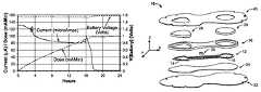
- FIG. 3is a chart of test data of one embodiment of the present invention.
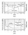
- FIG. 4is a chart of test data of another embodiment of the present invention.
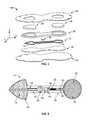
- FIG. 5is an exploded perspective view of one embodiment of the present invention.
- FIG. 6is a top view of one embodiment of the present invention.
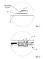
- FIG. 7is a side view of one embodiment of the present invention utilizing a Z-axis conductive tape.
- FIG. 8is a top view of the embodiment of the present invention shown in FIG. 7 .
- the present inventionprovides comparable control functionality of a more expensive iontophoresis drug delivery system without the need for sophisticated electronic circuitry and associated cables. More specifically, the present invention is directed to an integrated drug delivery system, e.g., electrotherapeutic.
- the systemis fully integrated within a housing. That is, cabling and such is unnecessary because the power source, controller, electrodes, hydratable matrices, etc., are integrated into a single housing.
- the systemincludes a current distribution element having the capability of varying its electrical resistance during operation to facilitate delivery of a drug dose. As such, the current distribution element, or a portion thereof, effectively functions as an electrochemical charge controlled rheostat-switch.
- a drug delivery system 10 of the present invention shown in FIG. 2includes a pair of metallic electrodes 14 , 16 —namely, a first electrode 14 including a resistance, and a second electrode 16 including a resistance.
- the electrodesare electric conductors through which an electric current enters or exits an electrochemical half-cell.
- An electrochemical half-cellmay be either an electrolytic half-cell or a galvanic half-cell.
- a single electrode and its associated ionic solution, e.g., electrolyte,compose one half-cell.
- the electrodescan be further distinguished as positive 14 (anode) and negative 16 (cathode).
- the present inventionprovides a mechanism whereby one or both of the electrodes 14 , 16 are designed to perform the dual functionality of an iontophoretic electrode and an electrochemical charge controlled rheostat-switch, wherein the rheostat-switch function does not interfere with the iontophoretic function of the electrode.
- the rheostat-switch functiondoes not introduce any detrimental impact on the medical safety and/or medical efficacy of the iontophoretic system.
- the positive iontophoretic electrodei.e., the iontophoretic anode
- the switching function in this embodimentis accomplished via electrochemical electroplating.
- the electroplated substanceis electrically non-conductive, and when the plating reaches a finite thickness—which completely encapsulates the original electrode surface—the iontophoretic current is effectively switched off.
- the variance of the resistance of this electrochemical charge controlled rheostat-switch functionalityis a function of accumulated charge.
- the basic switch characteristic of the electrochemical charge controlled rheostat-switch functionalityis that of a traditional normally closed ON-OFF switch, i.e., a device that provides relatively low electrical resistance when in the ON position (which facilitates the passage of electrical current) and provides relatively high electrical resistance when in the OFF position (which facilitates the blockage of electrical current). It is to be understood that the scope of the present invention is not limited to the basic operation of an ON-OFF switch and can include the variable resistive functionality akin to that of a rheostat, as well as a combination of the two.
- rheostat emulationprovides one electrical resistance level until one finite charge level is achieved and a second electrical resistance level after this finite charge level is achieved.
- This resistive varianceprovides a first magnitude of electrical current, i.e., a first level of dosing, followed by a different second magnitude of electrical current, i.e., a second level of dosing.
- the chemical properties and/or physical properties of one, or both of the electrochemical half-cells—comprising the electrode and associated electrolyte—is configured to facilitate the desired rheostat functionality.
- a current regulator 22(and a current limiter) may be operably connected to one or both of the electrodes 14 , 16 .
- a simplistic regulator 22 in the form of a resistor componentmay be utilized as an example of a low-cost implementation.
- the power source of the drug delivery system 10may be an electrochemical source such as a primary battery or a series of batteries. Alternatively, the power source may be an electrical generator and/or electrostatic storage device such as a capacitor or bank of capacitors.
- the current regulator 22is utilized to regulate electrical current as well as to provide current limitation.
- the current regulator 22may be connected to either electrode 14 , 16 .
- the electrochemical charge controlled rheostat-switch functionalityis an inherent part of the current distribution element 12 .
- one or both electrodes 14 , 16includes a metallic chemical composition capable of operable cooperation with an electrolyte solution—either the positive or negative electrolyte of the associated electrode.
- One of a pair of hydratable matrices 28 , 29is operably connected to each electrode 14 , 16 .
- Each hydratable matrix 28 , 29is associated with an electrode, 14 16 , i.e., the iontophoretic anode (positive electrode) and the iontophoretic cathode (negative electrode), respectively.
- a matrix pH buffermay or may not be required.
- the drug delivery system 10 of the present inventioncan be operably configured dependent upon the polarity of the drug to be delivered. That is, if the administered drug is formulated as a positive ionic medicament(s), then the electrode connected to the positive side of the power source is considered the drug delivery electrode; and the electrode connected to the negative side of the power source is considered the return electrode. And conversely, if the drug to be delivered is formulated as a negative ionic medicament(s), then the electrode connected to the negative side of the power source is the drug delivery electrode; and the electrode connected to the positive side of the power source is the return electrode. In the case where both positively and negatively charged drugs are to be delivered simultaneously, both electrodes function simultaneously as the drug delivery and return electrodes.
- the hydratable matrix associated with the drug delivery electrodecontains the ionic medicament; and the hydratable matrix associated with the return electrode contains the non-drug ionic electrolyte. That is, if a positive drug is to be iontophoretically delivered, the anode matrix is the drug delivery electrode matrix; otherwise it is the return electrode matrix. And if a negative drug is to be iontophoretically delivered, then the cathode electrode matrix is the drug delivery matrix, otherwise it is the return electrode matrix.
- a common iontophoretically delivered drugis Dexamethasone Sodium Phosphate (“Dex”).
- This ionic drug medicamenthas a negative polarity and if Dex is used with the embodiment shown in FIG. 2 , then ionic drug medicament is placed in the negative electrode's 16 associated matrix (not shown)—often referred to as the cathode reservoir matrix, cathode matrix, or anionic matrix; and a non-drug ionic solution (i.e., effectively inert ionic solution) is placed in the positive electrode's 14 associated matrix (not shown)—often referred to as the anode reservoir matrix, anode matrix, or cationic matrix.
- a chemical changeoccurs at one or both of the electrodes 14 , 16 due to the flow of electrical current and the chemical composition of the each electrode and its associated electrolyte, which results in the variation (e.g., increase) in resistance of the respective electrodes as a function of the accumulated charge. This increase in resistance will ultimately zero the electrical current in the electrotherapeutic device.
- One or both of the iontophoretic electrodes 14 , 16facilitate the electrochemical reaction during iontophoresis.
- the electrochemical reaction at one electrodei.e., at one half-cell, may be oxidation while the reaction at other electrode may be reduction.
- the electrochemical reactioncan be designed to facilitate a variance in electrical resistance. This variance in resistance can be the result of an additive process such as electroplating, or a subtractive process such as electroetching.
- the electrochemical charge controlled rheostat-switch functionalityis inherent in the composition of at least a portion of the current distribution element 12 associated with the return electrode 14 .
- the metal utilized for the return electrode 14is Ag (silver).
- the electrolyte utilized for operable cooperation with the return electrode 14is a medical grade saline solution (e.g., sodium chloride solution, 0.9%) and is a common non-drug electrolyte employed in an iontophoretic return electrode hydratable matrix.
- oxidation reactionsoccur at the return electrode 14 .
- the primary chemical reactionplates the Ag of the return electrode 14 with a AgCl surface layer. The plating increases the resistance of the return electrode 14 and after a finite charge is achieved, the resistance increases rapidly and significantly, thereby terminating the flow of iontophoretic current, i.e., terminating the dosing after the final desired dose is achieved.
- FIG. 3displays test results of one embodiment of the present invention showing the relationship between the voltage potential of the power source, i.e., battery, the iontophoretic current (measured in microAmps), and the dose, i.e., charge (measured in milliAmp-minutes). Note that milliAmp-minutes is a measurement of charge, and charge is the first integral of current with respect to time.
- a test load resistor of 5 kOhmsis operably connected to one of the electrodes 14 , 16 . The value of 5 kOhms is chosen to represent a minimal skin-body resistance. The observed battery voltage is relatively constant at approximately 1.55 Volts.
- the battery voltageincreases slightly when the resistance of the electrode functioning as the electrochemical charge controlled rheostat-switch increases significantly; that is, when the current is terminated at dose completion.
- the slight rise of battery voltageis typical and is due to the “unloading” of the battery.
- FIG. 3indicates that the drug delivery system 10 of the present invention will supply relative constant current until the resistance at the specified electrode increases to stop the current at completion of the dose delivery.
- One advantage of the present inventionis that the increasing resistance of the electrode terminates the dose as a function of actual accumulated dose, and therefore the operation is independent of time and skin resistance.
- the electrical characteristicsare shown for an embodiment of the present invention designed to provide a dosage of 100+/ ⁇ 15 mA-min (which guarantees a dose of at least 80 mA-min).
- the dose accuracy of this embodimentis less than that of one utilizing a more expensive and sophisticated electronic controller, but is suitable for a low-cost disposable drug delivery system. It can be seen from FIG. 3 that at about seventeen hours, the electrode is completely plated and the resistance increases significantly, which terminates the treatment at approximately 98 mA-min.
- the primary electrochemical reactioni.e., primary electrolytic reaction or primary oxidation reaction, that occurs at the return electrode 14 of the current distribution element 12 for this exemplification is Ag+Cl ⁇ ⁇ AgCl+e ⁇ .
- the electron “e”is required for the flow of electrical current.
- the AgClforms a layer on top of the Ag ink.
- AgClunlike Ag, is non-conductive.
- the accumulation or layering of AgClprovides the required high resistance to terminate the iontophoretic current and thereby terminate the iontophoretic dosing; thus providing the electrical open-switch functionality after the predetermined dose is accumulated.
- the current regulator 22When utilizing a simple and low cost resistor as the current regulator 22 , the value of the resistor is dependent upon the battery supply voltage, maximum required current, and the application.
- the current regulator 22also functions as a current limiter.
- the current limit for the illustrated embodimentis 300 microamperes—that is, the maximum nominal voltage of about 1.5 V is divided by the absolute minimum load resistance of zero (0) Ohms in series with the current limiting resistor of 5 kOhms to equal 300 ⁇ A.
- the current limitprotects against harm to the patient should the iontophoretic device be placed on damaged or broken skin wherein the skin resistance is relatively small. This concern is more critical for devices utilizing higher voltage power supplies, e.g., a 6 or 12 Volt system employing a series of multiple lithium battery cells.
- the table belowillustrates the characteristics of the simple current regulator 22 employing a 5 kOhm resistor with a 1.5 Volt power source. This configuration is satisfactory for low cost applications, but is inferior to an electronic semiconductor current regulator. For a 500% variance in resistance, the variance in current is reduced from 500% to 67%.
- an electronic semiconductor current regulatormay be implemented for applications requiring a more finite current and/or for applications requiring a more finite dosing period (because variance in current results in a proportional variance in dosing period for the finite dose set by the composition of the conductive distribution element).
- composition of either or both electrodes 14 , 16 of the current distribution element 12can be configured to facilitate differing resistance profiles, which further facilitates differing current profiles, which still further facilitates varying dosage profiles. Varying the physical and/or chemical properties of the electrodes 14 , 16 and/or the electrolyte within their respective associated matrices 28 , 29 will facilitate the required variances in current and/or dosing profiles.
- a second current profile shown in FIG. 4is typical for a treatment regimen requiring an initial bolus excitation followed by low-level baseline excitation.
- the graph of FIG. 4illustrates a modified current profile that was obtained by adding impurities to 75% of the surface area of the return electrode employed in the device having electrical characteristics shown in FIG. 3 . Comparing the current profile of the modified return electrode of FIG. 4 to the unmodified return electrode of FIG. 3 , the unmodified embodiment yields a relatively high current for approximately seventeen hours and then approximately zero current thereafter; and the modified embodiment of FIG. 4 yields a high current for approximately one hour followed by a low current the remaining twenty-three hours. Comparison of FIGS. 3 and 4 exemplify the difference between the ON-OFF switch and rheostat (multi-level) functionality of the present invention.
- the drug delivery system 10may include a breathable or non-breathable skin fixation material 32 .
- An adhesiveis located on one side of the skin fixation material 32 and faces toward a single coated medical pressure sensitive polypropylene film 34 to provide adhesion to it.
- the perimeter of the skin fixation material 32is greater than that of the single coated medical pressure sensitive polypropylene film 34 .
- the additional area outside the perimeter of the single coated medical pressure sensitive polypropylene film 34includes the adhesive that contacts the skin.
- the single coated medical pressure sensitive polypropylene film 34is coated on one side and holds the iontophoretic current distribution element 12 . That is, the area inside the perimeter of the single coated medical pressure sensitive polypropylene film 34 houses the electrical and electrochemical components that are attached to, or integral with, the current distribution element 12 .
- the single coated medical pressure sensitive polypropylene film 34provides a moisture barrier and prevents unwanted moisture (e.g., shower water) from entering into the device through the skin fixation material 32 .
- the polypropylene film 34also prevents moisture (i.e., the electrolyte added to the two hydrated matrices) from escaping from the device 10 through the skin fixation material 32 ; thus permitting the use of a “breathable” skin fixation material.
- the single coated medical pressure sensitive polypropylene film 34may be eliminated to reduce the cost of manufacturing.
- the adhesive side of the medical pressure sensitive polypropylene film 34faces toward the current distribution element 12 , polyethylene foam pad 36 , and the pair of matrices 28 , 29 .
- the perimeter of the electrodes 14 , 16is significantly less than that of the hydratable matrices 28 , 29 .
- the single coated medical pressure sensitive polypropylene film 34is adhered to the pair of matrices 28 , 29 in the area of the electrodes 14 , 16 that extends beyond the perimeter of the current distribution element 12 .
- the single coated medical pressure sensitive polypropylene film 34is also adhered to the current distribution element 12 and a polyethylene foam pad 36 .
- the polyethylene foam pad 36 with adhesive on both layersis attached to the pressure sensitive polypropylene film 34 and provides multiple functions.
- the polyethylene foam pad 36or equivalent, provides the required lateral moisture barrier (i.e., in the X and Y axes) surrounding both matrices 28 , 29 .
- the polyethylene foam pad 36is relatively thick in the Z-axis. Utilization of a foam material provides the required thickness without sacrificing the needed flexibility.
- the polyethylene foam pad 36is adhered to the single coated medical pressure sensitive polypropylene film 34 via the adhesive provided by both materials. This strong double adhesion provides a relatively strong seal around each electrode 14 , 16 and each matrix 28 , 29 . This feature reduces or prevents leakage of the electrolyte from the matrices 28 , 29 into the electrical component cavity; and also prevents electrolyte leakage from one electrode to the other electrode.
- the adhesive material on the bottom side of the polyethylene foam pad 36provides adhesion to the topside of the current distribution element 12 and the components attached to the topside of the current distribution element. This provides the top-level moisture-barrier seal for the electrical circuitry, e.g., power source, power source connector 30 , and current regulator.
- a release liner 40is held in place by the adhesion provided by the skin fixation material 32 and the polyethylene foam pad 36 .
- the release liner 40protects the skin fixation adhesive 32 and the polyethylene foam pad 36 until the device 10 is ready for use, at which point in time the release liner 40 is typically removed just after the matrices 28 , 29 are hydrated and just prior to applying the device to the skin.
- the openings in the release liner 40facilitate the hydration of the matrices 28 , 29 without the need to remove the release liner.
- a substrate 46 for the current distribution element 12is a polyester film, or an equivalent, e.g., an electrically non-conductive thin flexible substrate. Electrically conductive metal inks compose first 38 , second 42 , and third 44 conductors. Ag/AgCl ink 50 is deposited to fabricate the electrolytic iontophoretic cathode 16 and the first conductor 38 . Ag ink 48 is deposited to fabricate an electrolytic iontophoretic anode 14 and another two conductors 42 , 44 .
- An electrically resistive material such as carbon inkis deposited on the substrate 46 to fabricate an electrical resistor 22 in series with the first 38 and third 44 conductors, iontophoretic cathode 16 , and the power source connector 30 .
- the carbon ink resistor 22is printed in a manner similar to that used for printing the metallic inks.
- the resistor 22provides current regulation and current limit. It is to be understood that the present invention is not limited to this simple current regulator; and that it can incorporate a more sophisticated and precise current regulator and/or current limiter, or none at all.
- a dielectric ink 54may be printed over certain sections of the electrically conductive metal inks intended to function as insulated conductors.
- the embodiment shown in FIG. 6may utilize the same metal inks for both the cathode 16 and anode 14 that can also be used for the first 38 and third conductors 44 (as well as second conductor 42 ) respectively.
- Utilizing a single metal inkeliminates the need for a separate deposition of multiple metal inks to fabricate conductors and/or electrodes of existing flexible devices.
- the present inventioneliminates the need for separate metal ink depositions to fabricate separate conductors, thereby lowering manufacturing cost and enhancing reliability by reducing components, reducing manufacturing steps, and reducing the number of resultant physical/electrical interconnections.
- the metal inks employed to fabricate the electrodes 14 , 16 of the present inventionare not limited to Ag and Ag/AgCl.
- one metale.g., Ag
- the exclusive use of Agreduces the cost of manufacturing by employing only one metallic ink deposition to fabricate the two electrodes 14 , 16 and all of the separate interconnecting conductors.
- the exclusive use of Agdoes have one drawback in comparison to the Ag and Ag/AgCl embodiment presented herein—namely, the voltage required for reduction at the iontophoretic cathode is greater.
- the exclusive use of Agrequires a higher voltage power supply, e.g., a series of batteries as opposed to the single battery. Therefore, such tradeoffs should be considered when altering the materials used for the electrodes and/or electrolytes.
- FIGS. 7 and 8illustrate a further embodiment of the present invention directed to the connection of the power source with the current distribution element 12 .
- the power source in the illustrated embodimentis a tabbed button battery. It is to be understood that the present invention is not limited to this type of power source and may include among other embodiments, such as a connected series of multiple cells.
- the multiple cell embodimentprovides a higher voltage potential as required to drive higher resistance skin and/or provide iontophoresis of a finite dose in a shorter period of time by providing higher current for a given skin resistance.
- An electrically conductive tape 56 exclusively conductive in its Z-axis(e.g., 3MTM Electrically Conductive Tape 9703) is used to adhere and electrically connect the battery 30 to the conductors of the current distribution element 12 .
- This tapeis applicable for interconnection of silver ink/polyester based flexible circuits and provides stable electrical performance at moderately high temperatures with good adhesion to metallic and other commonly used surfaces, including: polyimide and polyester flex circuit materials, FR-4 board, copper, steel, and aluminum.
- the Z-axis conductive tapeis an isotropic, electrically conductive, pressure sensitive adhesive (PSA) transfer tape. It is tacky and consists of a PSA matrix with conductive particles.
- PSApressure sensitive adhesive
- This single-axis conduction featureallows one contiguous segment of Z-axis tape 56 to be used to simultaneously connect both the battery anode and battery cathode of the embodiment illustrated in FIG. 7 .
- implementation of the Z-axis tapeeliminates the need for two separate applications of a conductive adhesive at the battery anode tab and battery cathode tab of the battery; eliminates the need to maintain an insulation barrier between the battery anode tab connection and battery cathode tab connection; provides suitable mechanical adhesion in addition to the required electrical connections; eliminates the need for curing as required with metallized electrically conductive inks or electrically conductive paste type adhesives; decreases the probability of connection failure, e.g., the cracking of electrically conductive paste type adhesives when employed on a flexible substrate; and, is simpler to apply than electrically conductive paste type adhesives.
Landscapes
- Health & Medical Sciences (AREA)
- Engineering & Computer Science (AREA)
- Biomedical Technology (AREA)
- Nuclear Medicine, Radiotherapy & Molecular Imaging (AREA)
- Radiology & Medical Imaging (AREA)
- Life Sciences & Earth Sciences (AREA)
- Animal Behavior & Ethology (AREA)
- General Health & Medical Sciences (AREA)
- Public Health (AREA)
- Veterinary Medicine (AREA)
- Bioinformatics & Cheminformatics (AREA)
- Electrotherapy Devices (AREA)
Abstract
Description
| TABLE 1 | ||
| Skin-Body | Current with | Current without |
| Resistance | Regulation | Regulation |
| (Ohms) | (microAmps) | (microAmps) |
| 5,000 | 150 | 300 |
| 1,000 | 250 | 1,500 |
| 500% Variance | 67% Variance | 500% Variance |
Claims (18)
Priority Applications (4)
| Application Number | Priority Date | Filing Date | Title |
|---|---|---|---|
| US13/767,514US8781572B2 (en) | 2005-03-31 | 2013-02-14 | Method and apparatus for electrotherapy drug delivery |
| US14/295,120US9468757B2 (en) | 2005-03-31 | 2014-06-03 | Method and apparatus for electrotherapy drug delivery |
| US15/295,828US10478610B2 (en) | 2005-03-31 | 2016-10-17 | Method for electrotherapy drug delivery |
| US16/687,343US11541226B2 (en) | 2005-03-31 | 2019-11-18 | Method and apparatus for electrotherapy drug delivery |
Applications Claiming Priority (2)
| Application Number | Priority Date | Filing Date | Title |
|---|---|---|---|
| US10/907,429US8386029B2 (en) | 2005-03-31 | 2005-03-31 | Apparatus for electrotherapy drug delivery with added impurities |
| US13/767,514US8781572B2 (en) | 2005-03-31 | 2013-02-14 | Method and apparatus for electrotherapy drug delivery |
Related Parent Applications (1)
| Application Number | Title | Priority Date | Filing Date |
|---|---|---|---|
| US10/907,429ContinuationUS8386029B2 (en) | 2005-03-31 | 2005-03-31 | Apparatus for electrotherapy drug delivery with added impurities |
Related Child Applications (1)
| Application Number | Title | Priority Date | Filing Date |
|---|---|---|---|
| US14/295,120ContinuationUS9468757B2 (en) | 2005-03-31 | 2014-06-03 | Method and apparatus for electrotherapy drug delivery |
Publications (2)
| Publication Number | Publication Date |
|---|---|
| US20130226135A1 US20130226135A1 (en) | 2013-08-29 |
| US8781572B2true US8781572B2 (en) | 2014-07-15 |
Family
ID=36616937
Family Applications (5)
| Application Number | Title | Priority Date | Filing Date |
|---|---|---|---|
| US10/907,429Expired - Fee RelatedUS8386029B2 (en) | 2005-03-31 | 2005-03-31 | Apparatus for electrotherapy drug delivery with added impurities |
| US13/767,514Expired - LifetimeUS8781572B2 (en) | 2005-03-31 | 2013-02-14 | Method and apparatus for electrotherapy drug delivery |
| US14/295,120Expired - LifetimeUS9468757B2 (en) | 2005-03-31 | 2014-06-03 | Method and apparatus for electrotherapy drug delivery |
| US15/295,828Expired - LifetimeUS10478610B2 (en) | 2005-03-31 | 2016-10-17 | Method for electrotherapy drug delivery |
| US16/687,343Active2026-02-09US11541226B2 (en) | 2005-03-31 | 2019-11-18 | Method and apparatus for electrotherapy drug delivery |
Family Applications Before (1)
| Application Number | Title | Priority Date | Filing Date |
|---|---|---|---|
| US10/907,429Expired - Fee RelatedUS8386029B2 (en) | 2005-03-31 | 2005-03-31 | Apparatus for electrotherapy drug delivery with added impurities |
Family Applications After (3)
| Application Number | Title | Priority Date | Filing Date |
|---|---|---|---|
| US14/295,120Expired - LifetimeUS9468757B2 (en) | 2005-03-31 | 2014-06-03 | Method and apparatus for electrotherapy drug delivery |
| US15/295,828Expired - LifetimeUS10478610B2 (en) | 2005-03-31 | 2016-10-17 | Method for electrotherapy drug delivery |
| US16/687,343Active2026-02-09US11541226B2 (en) | 2005-03-31 | 2019-11-18 | Method and apparatus for electrotherapy drug delivery |
Country Status (4)
| Country | Link |
|---|---|
| US (5) | US8386029B2 (en) |
| EP (1) | EP1707236B1 (en) |
| JP (1) | JP4384128B2 (en) |
| ES (1) | ES2528238T3 (en) |
Cited By (1)
| Publication number | Priority date | Publication date | Assignee | Title |
|---|---|---|---|---|
| US10478610B2 (en) | 2005-03-31 | 2019-11-19 | Encore Medical Asset Corporation | Method for electrotherapy drug delivery |
Families Citing this family (17)
| Publication number | Priority date | Publication date | Assignee | Title |
|---|---|---|---|---|
| US20080177219A1 (en)* | 2007-01-23 | 2008-07-24 | Joshi Ashok V | Method for Iontophoretic Fluid Delivery |
| US8197844B2 (en) | 2007-06-08 | 2012-06-12 | Activatek, Inc. | Active electrode for transdermal medicament administration |
| US8862223B2 (en) | 2008-01-18 | 2014-10-14 | Activatek, Inc. | Active transdermal medicament patch and circuit board for same |
| WO2009158032A1 (en)* | 2008-06-25 | 2009-12-30 | Fe2, Inc. | Patches and methods for the transdermal delivery of a therapeutically effective amount of iron |
| US8190252B2 (en) | 2009-02-12 | 2012-05-29 | Incube Labs, Llc | Iontophoretic system for transdermal delivery of active agents for therapeutic and medicinal purposes |
| WO2010093472A2 (en)* | 2009-02-12 | 2010-08-19 | Incube Labs, Llc | Method and apparatus for oscillatory iontophoretic transdermal delivery of a therapeutic agent |
| US8961492B2 (en) | 2009-02-12 | 2015-02-24 | Incube Labs, Llc | System and method for controlling the iontophoretic delivery of therapeutic agents based on user inhalation |
| US8821945B2 (en)* | 2009-04-25 | 2014-09-02 | Fe3 Medical, Inc. | Method for transdermal iontophoretic delivery of chelated agents |
| US8417330B2 (en)* | 2009-06-26 | 2013-04-09 | Incube Labs, Llc | Corrosion resistant electrodes for iontophoretic transdermal delivery devices and methods of use |
| WO2011044175A2 (en) | 2009-10-06 | 2011-04-14 | Incube Labs, Llc | Patch and patch assembly for iontophoretic transdermal delivery of active agents for therapeutic and medicinal purposes |
| US8685038B2 (en) | 2009-12-07 | 2014-04-01 | Incube Labs, Llc | Iontophoretic apparatus and method for marking of the skin |
| WO2011100376A2 (en) | 2010-02-10 | 2011-08-18 | Incube Labs, Llc | Methods and architecture for power optimization of iontophoretic transdermal drug delivery |
| CN106955415B (en) | 2011-03-24 | 2019-06-18 | 因卡伯实验室有限责任公司 | The system and method for two stages percutaneous iontophoretic delivery for therapeutic agent |
| WO2012154704A2 (en) | 2011-05-06 | 2012-11-15 | Incube Labs, Llc | System and method for biphasic transdermal iontophoretic delivery of therapeutic agents for the control of addictive cravings |
| US9550043B2 (en) | 2012-12-13 | 2017-01-24 | Interrad Medical, Inc. | Systems and methods for anchoring medical devices |
| US9463307B2 (en) | 2012-12-21 | 2016-10-11 | Medtronic Xomed, Inc. | Sinus dilation system and method |
| AU2014296315A1 (en) | 2013-07-29 | 2016-02-18 | Kural Corp. | Therapeutic electron and ion transfer via half-cell |
Citations (28)
| Publication number | Priority date | Publication date | Assignee | Title |
|---|---|---|---|---|
| JPS5496076A (en) | 1978-01-13 | 1979-07-30 | Sumitomo Metal Mining Co | Long time switch |
| US4557723A (en) | 1983-08-18 | 1985-12-10 | Drug Delivery Systems Inc. | Applicator for the non-invasive transcutaneous delivery of medicament |
| US4622031A (en) | 1983-08-18 | 1986-11-11 | Drug Delivery Systems Inc. | Indicator for electrophoretic transcutaneous drug delivery device |
| US4640689A (en) | 1983-08-18 | 1987-02-03 | Drug Delivery Systems Inc. | Transdermal drug applicator and electrodes therefor |
| US4708716A (en) | 1983-08-18 | 1987-11-24 | Drug Delivery Systems Inc. | Transdermal drug applicator |
| US4919648A (en) | 1983-08-18 | 1990-04-24 | Drug Delivery Systems Inc. | High tack drug patch |
| US4921475A (en) | 1983-08-18 | 1990-05-01 | Drug Delivery Systems Inc. | Transdermal drug patch with microtubes |
| US4927408A (en) | 1988-10-03 | 1990-05-22 | Alza Corporation | Electrotransport transdermal system |
| US5087240A (en) | 1983-08-18 | 1992-02-11 | Drug Delivery Systems Inc. | Transdermal drug patch with conductive fibers |
| US5135479A (en) | 1983-08-18 | 1992-08-04 | Drug Delivery Systems, Inc. | Programmable control and mounting system for transdermal drug applicator |
| US5224928A (en) | 1983-08-18 | 1993-07-06 | Drug Delivery Systems Inc. | Mounting system for transdermal drug applicator |
| US5445606A (en)* | 1991-12-11 | 1995-08-29 | Alza Corporation | Indicator for iontophoresis system |
| WO1996030077A1 (en) | 1995-03-24 | 1996-10-03 | Alza Corporation | Self-contained transdermal drug delivery device |
| WO1996033771A2 (en) | 1995-04-28 | 1996-10-31 | Alza Corporation | Composition and method of enhancing electrotransport agent delivery |
| US5591123A (en) | 1983-08-18 | 1997-01-07 | Drug Delivery Systems Inc. | Programmable control mounting system for transdermal drug applicator |
| US5605536A (en) | 1983-08-18 | 1997-02-25 | Drug Delivery Systems Inc. | Transdermal drug applicator and electrodes therefor |
| US5651768A (en) | 1983-08-18 | 1997-07-29 | Drug Delivery Systems, Inc. | Transdermal drug applicator and electrodes therefor |
| US5865786A (en) | 1983-08-18 | 1999-02-02 | Drug Delivery Systems, Inc. | Programmable control and mounting system for transdermal drug applicator |
| WO1999012606A1 (en) | 1997-09-08 | 1999-03-18 | Becton Dickinson And Company | Iontophoretic delivery of buprenorphine |
| US5991655A (en) | 1997-03-03 | 1999-11-23 | Drug Delivery Systems, Inc. | Iontophoretic drug delivery device and method of manufacturing the same |
| US6141582A (en) | 1995-08-31 | 2000-10-31 | Hisamitsu Pharmaceutical Co., Ltd. | Iontophoresis system and its control process of current |
| WO2002002182A2 (en) | 2000-06-30 | 2002-01-10 | Vyteris, Inc. | Shelf storage stable iontophoresis reservoir-electrode and iontophoretic system |
| US20020010415A1 (en) | 2000-05-22 | 2002-01-24 | Simon Adam J. | System and method for assessing the performance of a pharmaceutical agent delivery system |
| US20030065285A1 (en) | 2001-07-23 | 2003-04-03 | Higuchi William I. | Method and apparatus for increasing flux during reverse iontophoresis |
| US20030149393A1 (en) | 2002-02-04 | 2003-08-07 | Joshi Ashok V. | Iontophoretic fluid delivery device |
| US6653014B2 (en) | 2001-05-30 | 2003-11-25 | Birch Point Medical, Inc. | Power sources for iontophoretic drug delivery systems |
| JP2004073613A (en) | 2002-08-21 | 2004-03-11 | Nippon Lumenis:Kk | Iontophoretic apparatus |
| US20040167460A1 (en) | 2003-02-21 | 2004-08-26 | Birch Point Medical, Inc. | Dosage control electrode for iontophoresis device |
Family Cites Families (10)
| Publication number | Priority date | Publication date | Assignee | Title |
|---|---|---|---|---|
| JP3488466B2 (en)* | 1992-06-02 | 2004-01-19 | アルザ・コーポレーション | Electric drive drug delivery device |
| US5895369A (en)* | 1994-09-30 | 1999-04-20 | Becton Dickinson And Company | Iontophoresis patch/controller interconnection using a conductive elastomer to provide noise-free electrical contact between patch and controller |
| US5645526A (en)* | 1994-09-30 | 1997-07-08 | Becton Dickinson And Company | Apparatus and method for ensuring compatibility of a reusable iontophoretic controller with an iontophoretic patch |
| IL162635A0 (en)* | 2001-12-20 | 2005-11-20 | Alza Corp | Electrotransport device having an integrally molded reservoir housing |
| US20050228335A1 (en)* | 2004-04-07 | 2005-10-13 | Reddy Vilambi N | Physical, structural, mechanical, electrical and electromechanical features for use in association with electrically assisted delivery devices and systems |
| US8386029B2 (en) | 2005-03-31 | 2013-02-26 | Encore Medical Asset Corporation | Apparatus for electrotherapy drug delivery with added impurities |
| US20120118741A1 (en)* | 2007-08-01 | 2012-05-17 | Blue Spark Technologies, Inc. | Integrated Electronic Device and Methods of Making the Same |
| US9421356B2 (en)* | 2007-08-28 | 2016-08-23 | Teikoku Pharma Usa, Inc. | Transdermal methods and systems for the delivery of corticosteroid compounds |
| CN102186535B (en)* | 2008-09-02 | 2015-09-30 | 帝国制药美国公司 | Sacrificial Electrode Design and Delivery Agent Types for Extended Iontophoresis Administration |
| US10476810B1 (en) | 2018-04-26 | 2019-11-12 | Hewlett Packard Enterprise Development Lp | Network source arbitration |
- 2005
- 2005-03-31USUS10/907,429patent/US8386029B2/ennot_activeExpired - Fee Related
- 2006
- 2006-02-09ESES06002614.3Tpatent/ES2528238T3/enactiveActive
- 2006-02-09EPEP06002614.3Apatent/EP1707236B1/enactiveActive
- 2006-03-23JPJP2006080910Apatent/JP4384128B2/enactiveActive
- 2013
- 2013-02-14USUS13/767,514patent/US8781572B2/ennot_activeExpired - Lifetime
- 2014
- 2014-06-03USUS14/295,120patent/US9468757B2/ennot_activeExpired - Lifetime
- 2016
- 2016-10-17USUS15/295,828patent/US10478610B2/ennot_activeExpired - Lifetime
- 2019
- 2019-11-18USUS16/687,343patent/US11541226B2/enactiveActive
Patent Citations (31)
| Publication number | Priority date | Publication date | Assignee | Title |
|---|---|---|---|---|
| JPS5496076A (en) | 1978-01-13 | 1979-07-30 | Sumitomo Metal Mining Co | Long time switch |
| US5591123A (en) | 1983-08-18 | 1997-01-07 | Drug Delivery Systems Inc. | Programmable control mounting system for transdermal drug applicator |
| US5224928A (en) | 1983-08-18 | 1993-07-06 | Drug Delivery Systems Inc. | Mounting system for transdermal drug applicator |
| US4640689A (en) | 1983-08-18 | 1987-02-03 | Drug Delivery Systems Inc. | Transdermal drug applicator and electrodes therefor |
| US5135479A (en) | 1983-08-18 | 1992-08-04 | Drug Delivery Systems, Inc. | Programmable control and mounting system for transdermal drug applicator |
| US6129696A (en) | 1983-08-18 | 2000-10-10 | Drug Delivery Systems Inc. | Transdermal drug applicator |
| US4919648A (en) | 1983-08-18 | 1990-04-24 | Drug Delivery Systems Inc. | High tack drug patch |
| US4921475A (en) | 1983-08-18 | 1990-05-01 | Drug Delivery Systems Inc. | Transdermal drug patch with microtubes |
| US5865786A (en) | 1983-08-18 | 1999-02-02 | Drug Delivery Systems, Inc. | Programmable control and mounting system for transdermal drug applicator |
| US4622031A (en) | 1983-08-18 | 1986-11-11 | Drug Delivery Systems Inc. | Indicator for electrophoretic transcutaneous drug delivery device |
| US5087240A (en) | 1983-08-18 | 1992-02-11 | Drug Delivery Systems Inc. | Transdermal drug patch with conductive fibers |
| US4708716A (en) | 1983-08-18 | 1987-11-24 | Drug Delivery Systems Inc. | Transdermal drug applicator |
| US5651768A (en) | 1983-08-18 | 1997-07-29 | Drug Delivery Systems, Inc. | Transdermal drug applicator and electrodes therefor |
| US5605536A (en) | 1983-08-18 | 1997-02-25 | Drug Delivery Systems Inc. | Transdermal drug applicator and electrodes therefor |
| US4557723A (en) | 1983-08-18 | 1985-12-10 | Drug Delivery Systems Inc. | Applicator for the non-invasive transcutaneous delivery of medicament |
| US5931804A (en) | 1983-08-18 | 1999-08-03 | Drug Delivery Systems, Inc. | Transdermal drug applicator and electrodes therefor |
| US4713050A (en) | 1984-10-12 | 1987-12-15 | Drug Delivery Systems Inc. | Applicator for non-invasive transcutaneous delivery of medicament |
| US4927408A (en) | 1988-10-03 | 1990-05-22 | Alza Corporation | Electrotransport transdermal system |
| US5445606A (en)* | 1991-12-11 | 1995-08-29 | Alza Corporation | Indicator for iontophoresis system |
| WO1996030077A1 (en) | 1995-03-24 | 1996-10-03 | Alza Corporation | Self-contained transdermal drug delivery device |
| WO1996033771A2 (en) | 1995-04-28 | 1996-10-31 | Alza Corporation | Composition and method of enhancing electrotransport agent delivery |
| US6141582A (en) | 1995-08-31 | 2000-10-31 | Hisamitsu Pharmaceutical Co., Ltd. | Iontophoresis system and its control process of current |
| US5991655A (en) | 1997-03-03 | 1999-11-23 | Drug Delivery Systems, Inc. | Iontophoretic drug delivery device and method of manufacturing the same |
| WO1999012606A1 (en) | 1997-09-08 | 1999-03-18 | Becton Dickinson And Company | Iontophoretic delivery of buprenorphine |
| US20020010415A1 (en) | 2000-05-22 | 2002-01-24 | Simon Adam J. | System and method for assessing the performance of a pharmaceutical agent delivery system |
| WO2002002182A2 (en) | 2000-06-30 | 2002-01-10 | Vyteris, Inc. | Shelf storage stable iontophoresis reservoir-electrode and iontophoretic system |
| US6653014B2 (en) | 2001-05-30 | 2003-11-25 | Birch Point Medical, Inc. | Power sources for iontophoretic drug delivery systems |
| US20030065285A1 (en) | 2001-07-23 | 2003-04-03 | Higuchi William I. | Method and apparatus for increasing flux during reverse iontophoresis |
| US20030149393A1 (en) | 2002-02-04 | 2003-08-07 | Joshi Ashok V. | Iontophoretic fluid delivery device |
| JP2004073613A (en) | 2002-08-21 | 2004-03-11 | Nippon Lumenis:Kk | Iontophoretic apparatus |
| US20040167460A1 (en) | 2003-02-21 | 2004-08-26 | Birch Point Medical, Inc. | Dosage control electrode for iontophoresis device |
Non-Patent Citations (8)
| Title |
|---|
| 510(k) Summary by EEMSO, Inc. dated Oct. 14, 2003, 3 pp. |
| EEMSO E-Strip Package-Photocopy of a package, Jul. 2003. |
| EEMSO E-Strip Package—Photocopy of a package, Jul. 2003. |
| EEMSO Website Info-1.JPG, http://eemso.com/ESTRIP.cfm, downloaded on Mar. 31, 2005, 1 page. |
| EEMSO Website Info-2.JPG, http://eemso.com/ESTRIP.cfm, downloaded on Mar. 31, 2005, 1 page. |
| European Extended Search Report and European Search Opinion dated Sep. 24, 2009 in International Application No. 06002614.3. |
| Letter to EEMSO, Inc. from Department of Health & Human Services dated Oct. 14, 2003, 3 pp. |
| Linde, "Technical Brief Polymer Thick Film Resistors: Application and Design Criteria," (1997), Microelectronics International, vol. 14, No. 2, p. 65. |
Cited By (2)
| Publication number | Priority date | Publication date | Assignee | Title |
|---|---|---|---|---|
| US10478610B2 (en) | 2005-03-31 | 2019-11-19 | Encore Medical Asset Corporation | Method for electrotherapy drug delivery |
| US11541226B2 (en) | 2005-03-31 | 2023-01-03 | Encore Medical Asset Corporation | Method and apparatus for electrotherapy drug delivery |
Also Published As
| Publication number | Publication date |
|---|---|
| US10478610B2 (en) | 2019-11-19 |
| US20140288482A1 (en) | 2014-09-25 |
| EP1707236B1 (en) | 2014-10-22 |
| US8386029B2 (en) | 2013-02-26 |
| US20130226135A1 (en) | 2013-08-29 |
| EP1707236A3 (en) | 2009-10-28 |
| EP1707236A2 (en) | 2006-10-04 |
| US20060229549A1 (en) | 2006-10-12 |
| JP4384128B2 (en) | 2009-12-16 |
| US20170128714A1 (en) | 2017-05-11 |
| US11541226B2 (en) | 2023-01-03 |
| US20200139105A1 (en) | 2020-05-07 |
| JP2006280924A (en) | 2006-10-19 |
| US9468757B2 (en) | 2016-10-18 |
| ES2528238T3 (en) | 2015-02-06 |
Similar Documents
| Publication | Publication Date | Title |
|---|---|---|
| US11541226B2 (en) | Method and apparatus for electrotherapy drug delivery | |
| US7031768B2 (en) | Controlled dosage drug delivery | |
| US7016723B2 (en) | Rate adjustable drug delivery system | |
| US6653014B2 (en) | Power sources for iontophoretic drug delivery systems | |
| US6775570B2 (en) | Iontophoretic treatment device | |
| US7047069B2 (en) | Iontophoretic fluid delivery device | |
| JP4262410B2 (en) | Electrical transmission electrode assembly with low initial resistance | |
| JP4249629B2 (en) | Biological electrode | |
| US6584349B1 (en) | Low cost electrodes for an iontophoretic device | |
| US20100106075A1 (en) | Method for iontophoretic fluid delivery | |
| EP1925334A1 (en) | Iontophoresis device and power supply device for iontophoresis device | |
| EP1718363B1 (en) | Iontophoretic electrode | |
| MX2008003523A (en) | Iontophoresis device and power supply device for iontophoresis device |
Legal Events
| Date | Code | Title | Description |
|---|---|---|---|
| FEPP | Fee payment procedure | Free format text:PAYOR NUMBER ASSIGNED (ORIGINAL EVENT CODE: ASPN); ENTITY STATUS OF PATENT OWNER: LARGE ENTITY | |
| AS | Assignment | Owner name:ENCORE MEDICAL ASSET CORPORATION, NEVADA Free format text:ASSIGNMENT OF ASSIGNORS INTEREST;ASSIGNOR:IOMED, LLC;REEL/FRAME:033022/0626 Effective date:20070907 Owner name:IOMED, LLC, UTAH Free format text:CHANGE OF NAME;ASSIGNOR:IOMED, INC.;REEL/FRAME:033083/0182 Effective date:20070810 Owner name:IOMED, INC., UTAH Free format text:ASSIGNMENT OF ASSIGNORS INTEREST;ASSIGNORS:HAUSE, ROBERT F., JR.;BECK, JON E.;REEL/FRAME:033022/0705 Effective date:20050404 | |
| STCF | Information on status: patent grant | Free format text:PATENTED CASE | |
| AS | Assignment | Owner name:WELLS FARGO BANK, NATIONAL ASSOCIATION, AS THE COL Free format text:SECURITY INTEREST;ASSIGNORS:DJO, LLC;EMPI, INC.;ENCORE MEDICAL ASSET CORPORATION;AND OTHERS;REEL/FRAME:035614/0001 Effective date:20150507 | |
| AS | Assignment | Owner name:THE BANK OF NEW YORK MELLON, AS SECOND LIEN AGENT, Free format text:SECURITY AGREEMENT;ASSIGNORS:DJO, LLC;EMPI, INC.;ENCORE MEDICAL ASSET CORPORATION;AND OTHERS;REEL/FRAME:035707/0454 Effective date:20150507 Owner name:THE BANK OF NEW YORK MELLON, AS THIRD LIEN AGENT, Free format text:SECURITY AGREEMENT;ASSIGNORS:DJO, LLC;EMPI, INC.;ENCORE MEDICAL ASSET CORPORATION;AND OTHERS;REEL/FRAME:035707/0498 Effective date:20150507 Owner name:MACQUARIE US TRADING LLC, AS COLLATERAL AGENT, ILL Free format text:SECURITY AGREEMENT;ASSIGNORS:DJO, LLC;EMPI, INC.;ENCORE MEDICAL ASSET CORPORATION;AND OTHERS;REEL/FRAME:035707/0398 Effective date:20150507 | |
| MAFP | Maintenance fee payment | Free format text:PAYMENT OF MAINTENANCE FEE, 4TH YEAR, LARGE ENTITY (ORIGINAL EVENT CODE: M1551) Year of fee payment:4 | |
| AS | Assignment | Owner name:DJO, LLC, CALIFORNIA Free format text:RELEASE BY SECURED PARTY;ASSIGNOR:MACQUARIE US TRADING LLC AS COLLATERAL AGENT;REEL/FRAME:048655/0067 Effective date:20190222 Owner name:EMPI, INC., CALIFORNIA Free format text:RELEASE BY SECURED PARTY;ASSIGNOR:MACQUARIE US TRADING LLC AS COLLATERAL AGENT;REEL/FRAME:048655/0067 Effective date:20190222 Owner name:ENCORE MEDICAL ASSET CORPORATION, CALIFORNIA Free format text:RELEASE BY SECURED PARTY;ASSIGNOR:MACQUARIE US TRADING LLC AS COLLATERAL AGENT;REEL/FRAME:048655/0067 Effective date:20190222 Owner name:RIKCO INTERNATIONAL, LLC, CALIFORNIA Free format text:RELEASE BY SECURED PARTY;ASSIGNOR:MACQUARIE US TRADING LLC AS COLLATERAL AGENT;REEL/FRAME:048655/0067 Effective date:20190222 Owner name:ENCORE MEDICAL, L.P., CALIFORNIA Free format text:RELEASE BY SECURED PARTY;ASSIGNOR:MACQUARIE US TRADING LLC AS COLLATERAL AGENT;REEL/FRAME:048655/0067 Effective date:20190222 Owner name:DJO, LLC, CALIFORNIA Free format text:RELEASE BY SECURED PARTY;ASSIGNOR:THE BANK OF NEW YORK MELLON AS THIRD LIEN AGENT;REEL/FRAME:048608/0932 Effective date:20190222 Owner name:ENCORE MEDICAL ASSET CORPORATION, CALIFORNIA Free format text:RELEASE BY SECURED PARTY;ASSIGNOR:THE BANK OF NEW YORK MELLON AS THIRD LIEN AGENT;REEL/FRAME:048608/0932 Effective date:20190222 Owner name:RIKCO INTERNATIONAL, LLC, CALIFORNIA Free format text:RELEASE BY SECURED PARTY;ASSIGNOR:THE BANK OF NEW YORK MELLON AS THIRD LIEN AGENT;REEL/FRAME:048608/0932 Effective date:20190222 Owner name:EMPI, INC., CALIFORNIA Free format text:RELEASE BY SECURED PARTY;ASSIGNOR:THE BANK OF NEW YORK MELLON AS THIRD LIEN AGENT;REEL/FRAME:048608/0932 Effective date:20190222 Owner name:ENCORE MEDICAL, L.P., CALIFORNIA Free format text:RELEASE BY SECURED PARTY;ASSIGNOR:THE BANK OF NEW YORK MELLON AS THIRD LIEN AGENT;REEL/FRAME:048608/0932 Effective date:20190222 Owner name:EMPI, INC., CALIFORNIA Free format text:RELEASE BY SECURED PARTY;ASSIGNOR:THE BANK OF NEW YORK MELLON AS SECOND LIEN AGENT;REEL/FRAME:050129/0262 Effective date:20190222 Owner name:DJO, LLC, CALIFORNIA Free format text:RELEASE BY SECURED PARTY;ASSIGNOR:THE BANK OF NEW YORK MELLON AS SECOND LIEN AGENT;REEL/FRAME:050129/0262 Effective date:20190222 Owner name:RIKCO INTERNATIONAL, LLC, CALIFORNIA Free format text:RELEASE BY SECURED PARTY;ASSIGNOR:THE BANK OF NEW YORK MELLON AS SECOND LIEN AGENT;REEL/FRAME:050129/0262 Effective date:20190222 Owner name:ENCORE MEDICAL ASSET CORPORATION, CALIFORNIA Free format text:RELEASE BY SECURED PARTY;ASSIGNOR:THE BANK OF NEW YORK MELLON AS SECOND LIEN AGENT;REEL/FRAME:050129/0262 Effective date:20190222 Owner name:ENCORE MEDICAL, L.P., CALIFORNIA Free format text:RELEASE BY SECURED PARTY;ASSIGNOR:THE BANK OF NEW YORK MELLON AS SECOND LIEN AGENT;REEL/FRAME:050129/0262 Effective date:20190222 | |
| AS | Assignment | Owner name:EMPI, INC., CALIFORNIA Free format text:RELEASE BY SECURED PARTY;ASSIGNOR:WELLS FARGO BANK, NATIONAL ASSOCIATION AS COLLATERAL AGENT;REEL/FRAME:048672/0661 Effective date:20190222 Owner name:DJO, LLC, CALIFORNIA Free format text:RELEASE BY SECURED PARTY;ASSIGNOR:WELLS FARGO BANK, NATIONAL ASSOCIATION AS COLLATERAL AGENT;REEL/FRAME:048672/0661 Effective date:20190222 Owner name:RIKCO INTERNATIONAL, LLC, CALIFORNIA Free format text:RELEASE BY SECURED PARTY;ASSIGNOR:WELLS FARGO BANK, NATIONAL ASSOCIATION AS COLLATERAL AGENT;REEL/FRAME:048672/0661 Effective date:20190222 Owner name:ENCORE MEDICAL, L.P., CALIFORNIA Free format text:RELEASE BY SECURED PARTY;ASSIGNOR:WELLS FARGO BANK, NATIONAL ASSOCIATION AS COLLATERAL AGENT;REEL/FRAME:048672/0661 Effective date:20190222 Owner name:ENCORE MEDICAL ASSET CORPORATION, CALIFORNIA Free format text:RELEASE BY SECURED PARTY;ASSIGNOR:WELLS FARGO BANK, NATIONAL ASSOCIATION AS COLLATERAL AGENT;REEL/FRAME:048672/0661 Effective date:20190222 | |
| MAFP | Maintenance fee payment | Free format text:PAYMENT OF MAINTENANCE FEE, 8TH YEAR, LARGE ENTITY (ORIGINAL EVENT CODE: M1552); ENTITY STATUS OF PATENT OWNER: LARGE ENTITY Year of fee payment:8 | |
| AS | Assignment | Owner name:JPMORGAN CHASE BANK, N.A., AS ADMINISTRATIVE AGENT, ILLINOIS Free format text:SECURITY INTEREST;ASSIGNOR:DJO, LLC;REEL/FRAME:066186/0659 Effective date:20240103 |