US8780479B1 - Disk drive executing jerk seeks to rotate pivot ball bearings relative to races - Google Patents
Disk drive executing jerk seeks to rotate pivot ball bearings relative to racesDownload PDFInfo
- Publication number
- US8780479B1 US8780479B1US13/925,820US201313925820AUS8780479B1US 8780479 B1US8780479 B1US 8780479B1US 201313925820 AUS201313925820 AUS 201313925820AUS 8780479 B1US8780479 B1US 8780479B1
- Authority
- US
- United States
- Prior art keywords
- seek
- jerk
- vcm
- execute
- recited
- Prior art date
- Legal status (The legal status is an assumption and is not a legal conclusion. Google has not performed a legal analysis and makes no representation as to the accuracy of the status listed.)
- Expired - Fee Related
Links
Images


Classifications
- G—PHYSICS
- G11—INFORMATION STORAGE
- G11B—INFORMATION STORAGE BASED ON RELATIVE MOVEMENT BETWEEN RECORD CARRIER AND TRANSDUCER
- G11B5/00—Recording by magnetisation or demagnetisation of a record carrier; Reproducing by magnetic means; Record carriers therefor
- G11B5/48—Disposition or mounting of heads or head supports relative to record carriers ; arrangements of heads, e.g. for scanning the record carrier to increase the relative speed
- G11B5/54—Disposition or mounting of heads or head supports relative to record carriers ; arrangements of heads, e.g. for scanning the record carrier to increase the relative speed with provision for moving the head into or out of its operative position or across tracks
- G11B5/55—Track change, selection or acquisition by displacement of the head
- G11B5/5521—Track change, selection or acquisition by displacement of the head across disk tracks
- G11B5/5526—Control therefor; circuits, track configurations or relative disposition of servo-information transducers and servo-information tracks for control thereof
- G11B5/553—Details
- G11B5/5547—"Seek" control and circuits therefor
Definitions
- Disk drivescomprise a disk and a head connected to a distal end of an actuator arm which is rotated about a pivot by a voice coil motor (VCM) to position the head radially over the disk.
- VCMvoice coil motor
- the diskcomprises a plurality of radially spaced, concentric tracks for recording user data sectors and servo sectors.
- the servo sectorscomprise head positioning information (e.g., a track address) which is read by the head and processed by a servo control system to control the actuator arm as it seeks from track to track.
- FIG. 1shows a prior art disk format 2 as comprising a number of servo tracks 4 defined by servo sectors 6 0 - 6 N recorded around the circumference of each servo track.
- Each servo sector 6 icomprises a preamble 8 for storing a periodic pattern, which allows proper gain adjustment and timing synchronization of the read signal, and a sync mark 10 for storing a special pattern used to symbol synchronize to a servo data field 12 .
- the servo data field 12stores coarse head positioning information, such as a servo track address, used to position the head over a target data track during a seek operation.
- Each servo sector 6 ifurther comprises groups of servo bursts 14 (e.g., N and Q servo bursts), which are recorded with a predetermined phase relative to one another and relative to the servo track centerlines.
- the phase based servo bursts 14provide fine head position information used for centerline tracking while accessing a data track during write/read operations.
- a position error signal(PES) is generated by reading the servo bursts 14 , wherein the PES represents a measured position of the head relative to a centerline of a target servo track.
- a servo controllerprocesses the PES to generate a control signal applied to a head actuator (e.g., a voice coil motor) in order to actuate the head radially over the disk in a direction that reduces the PES.
- a head actuatore.g., a voice coil motor
- FIG. 1shows a prior art disk format comprising a plurality of tracks defined by servo sectors.
- FIG. 2Ashows a disk drive according to an embodiment comprising a head actuated over a disk by a voice coil motor (VCM) comprising a pivot bearing.
- VCMvoice coil motor
- FIG. 2Bshows a pivot bearing according to an embodiment comprising a race and a plurality of ball bearings.
- FIG. 2Cis a flow diagram according to an embodiment wherein first and second jerk seeks are executed in a first radial direction so that the ball bearings slip within the race in order to rotate the ball bearings relative to the race at a reference angle of the pivot bearing.
- FIG. 2Dillustrates one of the ball bearings slipping within the race by an accumulated rotation angle after executing successive jerk seeks according to an embodiment.
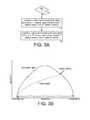
- FIG. 3Ais a flow diagram according to an embodiment wherein during an idle mode a jerk seek is executed from a first track to a second track, and then a second non-jerk seek is executed from the second track back to the first track.
- FIG. 3Bshows an embodiment wherein a jerk force is applied to the pivot bearing at the transition from acceleration to deceleration in a state trajectory.
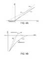
- FIGS. 4A and 4Bshow a normal seek state trajectory and jerk seek state trajectory which may result in an overshoot or an undershoot.
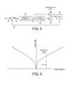
- FIG. 5shows a servo control system wherein one or more notch filters are disabled in order to execute a jerk seek according to an embodiment.
- FIG. 6shows an embodiment wherein a jerk seek is executed based on a seek length range, wherein the seek time is increased due to the jerk seek.
- FIG. 7is a flow diagram according to an embodiment wherein a jerk seek may be executed during normal operation when the rotational latency of a host command exceeds a threshold.
- FIG. 2Ashows a disk drive according to an embodiment comprising a disk 16 comprising a plurality of tracks 18 , a head 20 attached to a distal end of an actuator arm 21 , and a voice coil motor (VCM) 22 operable to rotate the actuator arm 21 about a pivot bearing 24 ( FIG. 2B ) including a race and a plurality of ball bearings (e.g., ball bearing 26 ).
- the disk drivefurther comprises control circuitry 28 operable to execute the flow diagram of FIG. 2C , wherein the VCM is controlled to execute a first jerk seek in a first radial direction so that the ball bearings slip within the race by a first rotation angle (block 30 ).
- the VCMis controlled to execute a second jerk seek in the first radial direction so that the ball bearings slip within the race by a second rotation angle (block 32 ), wherein the second rotation angle adds to the first rotation angle in order to rotate the ball bearings relative to the race at a reference angle of the pivot bearing 24 as illustrated in FIGS. 2B and 2D . That is, during a jerk seek the momentum will cause the ball bearings to slip within the race such that when the pivot bearing 24 is at a particular reference angle, the surface of the ball bearings relative to the race will have changed. In one embodiment, changing the ball bearing/race surface contact over time may help reduce friction effects.
- control circuitry 28is operable to control the VCM 22 to execute a number of jerk seeks in the first direction to cause the ball bearings to rotate at least 180 degrees relative to the race at the reference angle of the pivot bearing 24 .
- the ball bearingswill rotate within the race by at least 180 degrees after performing approximately eight jerk seeks toward the inner diameter (ID) of the disk 16 .
- the jerk seeksmay be executed by seeking the head toward the outer diameter (OD) of the disk 16 (rather than the ID) so that the ball bearings rotate in the reverse direction when slipping within the race.
- control circuitry 28may execute a first number of jerk seeks in one radial direction, and a second number of jerk seeks in an opposite radial direction, wherein the second number is greater than the first number resulting in net movement of the ball bearings within the race.
- the tracks 18 on the disk 16are defined by servo sectors 34 0 - 34 N .
- the control circuitry 28processes a read signal 36 emanating from the head 20 to demodulate the servo sectors 34 0 - 34 N and generate a position error signal (PES) representing an error between the actual position of the head and a target position relative to a target track.
- PESposition error signal
- the control circuitry 28filters the PES using a suitable compensation filter to generate a control signal 38 applied to the VCM 22 which rotates the actuator arm 21 about the pivot bearing 24 in order to actuate the head 20 radially over the disk 16 in a direction that reduces the PES.
- the servo sectors 34 0 - 34 Nmay comprise any suitable head position information, such as a track address for coarse positioning and servo bursts for fine positioning.
- the servo burstsmay comprise any suitable pattern, such as an amplitude based servo pattern or a phase based servo pattern.
- the control circuitry 28may execute a jerk seek during an idle mode when not servicing host commands.
- the disk 16may be written in a shingled mode using log structured writes where data is written to consecutive (overlapping) data tracks requiring only single track seeks.
- the control circuitry 28may execute the flow diagram of FIG. 3A wherein after detecting the idle mode (block 42 ) the VCM may be controlled to execute a jerk seek to seek the head from a first track (e.g., current track) to a second track (block 44 ). The VCM may then be controlled to execute a non-jerk seek to seek the head from the second track back to the first track (block 46 ).
- the jerk seekcauses the ball bearings to slip within the race due to a jerk force, whereas the non-jerk seek has minimal jerk force and therefore essentially no slipping of the ball bearings within the race. In this manner, the slipping of the ball bearings within the race during the jerk seek is preserved when the head is returned to the first track.
- the control circuitry 28may control the VCM 22 in any suitable manner in order to execute a jerk seek that causes the ball bearings to slip within the race.
- the control circuitry 28controls the VCM relative to a first state trajectory to execute the a jerk seek in a first radial direction (toward the ID), and then controls the VCM relative to a second state trajectory to execute a non-jerk seek in a second radial direction opposite the first radial direction.
- Any suitable non-jerk seekmay be employed, such as a normal seek executed while accessing data from the disk during an access operation, or a less aggressive seek that is slower than a normal seek.
- the state trajectorymay be designed to generate a jerk force at any suitable time during the seek, wherein in the embodiment shown in FIG. 3B , the state trajectory causes a jerk force when transitioning from an acceleration trajectory to a deceleration trajectory.
- the state trajectorycomprises a smoother transition from acceleration to deceleration, and therefore a lesser amount of jerk force is applied to the pivot bearing 24 .
- the state trajectory for the jerk seekdeviates from a normal (optimal) state trajectory, and therefore the resulting seek performance is suboptimal.
- FIGS. 4A and 4Billustrate an embodiment wherein the state trajectory 48 A of a normal seek results in an optimal (minimal) seek time 48 B to the target track.
- the state trajectory 50 A of a jerk seekcauses the head to overshoot 50 B the target track
- the state trajectory 52 A of a jerk seekcauses the head to undershoot 52 B the target track as illustrated in FIG. 4B .
- FIG. 5shows a servo control system implemented by the control circuitry 28 for seeking the head 20 over the disk 16 according to an embodiment, wherein the measured position 54 of the head (as determined from reading the servo sectors) is subtracted from a reference position 56 to generate the PES 58 .
- the PES 58is filtered by a feedback compensator 60 to generate a compensated control signal 62 .
- the compensated control signal 62is filtered by one or more notch filters 64 to generate the control signal 38 applied to the VCM 22 .
- a multiplexer 66is configured to disable the notch filter(s) 64 such that the compensated control signal 62 is applied directly to the VCM 22 .
- disabling the notch filter(s) 64causes the desired jerk force to be applied to the pivot bearing 24 during the jerk seek.
- the control circuitry 28executes a jerk seek for a desired seek length.
- a particular seek lengthmay correspond to a state trajectory that provides a desired amount of jerk force during the seek.
- the seek lengthmay correspond to a normal state trajectory wherein the velocity of the VCM 22 accelerates to a peak velocity and then transition into a deceleration trajectory which may maximize the jerk force of the jerk seek, whereas a shorter seek length may not reach a high enough velocity, and a longer seek length may exhibit less jerk force when transitioning from a constant velocity to the deceleration trajectory.
- FIG. 1one embodiment illustrated in FIG.
- the control circuitry 28may execute a jerk seek when servicing a host command if the seek length for the host command falls within a target seek length range. That is, if the seek length falls within the target seek length range, executing a jerk seek will apply the desired jerk force to the pivot bearing 24 .
- FIG. 6also illustrates that when a jerk seek is executed over the seek length range, the seek time is increased as compared to a normal seek due to the above described suboptimal performance of a jerk seek.
- the control circuitry 28executes a jerk seek only if the increased seek time of the jerk seek will not degrade performance. For example, in one embodiment the control circuitry may select a host command from a command queue based on a rotation position optimization (RPO) algorithm based on a seek and rotational latency for each host command. The control circuitry 28 may then execute a jerk seek if the rotational latency of the selected host command exceeds a threshold such that the extra seek time of a jerk seek will not cause a slipped disk revolution.
- RPOrotation position optimization
- An RPO algorithmis then executed to select the host command from the command queue that has the minimal seek and rotational latency (block 72 ). If a jerk seek is needed, for example, if N consecutive normal seeks have been executed without executing a jerk seek (block 73 ), and if the seek direction for the selected host command is in the desired radial direction (block 74 ) such as toward the ID, and the seek length of the selected host command falls within a target seek length range (block 76 ), and the rotational latency of the selected host command exceeds a threshold (block 78 ), then a jerk seek is executed (block 80 ) in order to change the ball bearing/race surface contact. Otherwise, a normal seek is executed (block 82 ) for the selected host command. Over time as a sufficient number of host commands meet the criteria of FIG. 7 , the accumulated jerk seeks will cause the ball bearing/race surface contact to be periodically renewed.
- the flow diagram of FIG. 7may be modified to determine first whether a jerk seek is needed before the RPO algorithm selects the next host command to execute from the command queue. If a jerk seek is needed, the RPO algorithm may be modified to select a host command that satisfies the criteria for a jerk seek (e.g., toward ID, sufficient seek length, rotation latency greater than a threshold, etc.). If none of the host commands in the command queue satisfy the criteria for a jerk seek, in one embodiment the control circuitry may interrupt the host command processing in order to force a jerk seek.
- the criteria for a jerk seeke.g., toward ID, sufficient seek length, rotation latency greater than a threshold, etc.
- control circuitrymay be implemented within a read channel integrated circuit, or in a component separate from the read channel, such as a disk controller, or certain operations described above may be performed by a read channel and others by a disk controller.
- the read channel and disk controllerare implemented as separate integrated circuits, and in an alternative embodiment they are fabricated into a single integrated circuit or system on a chip (SOC).
- the control circuitrymay include a suitable preamp circuit implemented as a separate integrated circuit, integrated into the read channel or disk controller circuit, or integrated into a SOC.
- control circuitrycomprises a microprocessor executing instructions, the instructions being operable to cause the microprocessor to perform the flow diagrams described herein.
- the instructionsmay be stored in any computer-readable medium. In one embodiment, they may be stored on a non-volatile semiconductor memory external to the microprocessor, or integrated with the microprocessor in a SOC. In another embodiment, the instructions are stored on the disk and read into a volatile semiconductor memory when the disk drive is powered on. In yet another embodiment, the control circuitry comprises suitable logic circuitry, such as state machine circuitry.
Landscapes
- Moving Of Head For Track Selection And Changing (AREA)
- Moving Of The Head To Find And Align With The Track (AREA)
- Moving Of Heads (AREA)
Abstract
Description
Claims (28)
Priority Applications (3)
| Application Number | Priority Date | Filing Date | Title |
|---|---|---|---|
| US13/925,820US8780479B1 (en) | 2013-05-17 | 2013-06-24 | Disk drive executing jerk seeks to rotate pivot ball bearings relative to races |
| CN201410283285.4ACN104240726A (en) | 2013-05-17 | 2014-05-16 | Disk drive executing jerk seeks to rotate pivot ball bearings relative to races |
| HK15105585.3AHK1205342A1 (en) | 2013-05-17 | 2015-06-12 | Disk drive executing jerk seeks to rotate pivot ball bearings relative to races |
Applications Claiming Priority (2)
| Application Number | Priority Date | Filing Date | Title |
|---|---|---|---|
| US201361824552P | 2013-05-17 | 2013-05-17 | |
| US13/925,820US8780479B1 (en) | 2013-05-17 | 2013-06-24 | Disk drive executing jerk seeks to rotate pivot ball bearings relative to races |
Publications (1)
| Publication Number | Publication Date |
|---|---|
| US8780479B1true US8780479B1 (en) | 2014-07-15 |
Family
ID=51135695
Family Applications (1)
| Application Number | Title | Priority Date | Filing Date |
|---|---|---|---|
| US13/925,820Expired - Fee RelatedUS8780479B1 (en) | 2013-05-17 | 2013-06-24 | Disk drive executing jerk seeks to rotate pivot ball bearings relative to races |
Country Status (3)
| Country | Link |
|---|---|
| US (1) | US8780479B1 (en) |
| CN (1) | CN104240726A (en) |
| HK (1) | HK1205342A1 (en) |
Cited By (75)
| Publication number | Priority date | Publication date | Assignee | Title |
|---|---|---|---|---|
| US8917474B1 (en) | 2011-08-08 | 2014-12-23 | Western Digital Technologies, Inc. | Disk drive calibrating a velocity profile prior to writing a spiral track |
| US8917475B1 (en) | 2013-12-20 | 2014-12-23 | Western Digital Technologies, Inc. | Disk drive generating a disk locked clock using radial dependent timing feed-forward compensation |
| US8922937B1 (en) | 2012-04-19 | 2014-12-30 | Western Digital Technologies, Inc. | Disk drive evaluating multiple vibration sensor outputs to enable write-protection |
| US8922938B1 (en) | 2012-11-02 | 2014-12-30 | Western Digital Technologies, Inc. | Disk drive filtering disturbance signal and error signal for adaptive feed-forward compensation |
| US8929022B1 (en) | 2012-12-19 | 2015-01-06 | Western Digital Technologies, Inc. | Disk drive detecting microactuator degradation by evaluating frequency component of servo signal |
| US8937784B1 (en) | 2012-08-01 | 2015-01-20 | Western Digital Technologies, Inc. | Disk drive employing feed-forward compensation and phase shift compensation during seek settling |
| US8941939B1 (en) | 2013-10-24 | 2015-01-27 | Western Digital Technologies, Inc. | Disk drive using VCM BEMF feed-forward compensation to write servo data to a disk |
| US8947819B1 (en) | 2012-08-28 | 2015-02-03 | Western Digital Technologies, Inc. | Disk drive implementing hysteresis for primary shock detector based on a more sensitive secondary shock detector |
| US8953278B1 (en) | 2011-11-16 | 2015-02-10 | Western Digital Technologies, Inc. | Disk drive selecting disturbance signal for feed-forward compensation |
| US8970979B1 (en) | 2013-12-18 | 2015-03-03 | Western Digital Technologies, Inc. | Disk drive determining frequency response of actuator near servo sample frequency |
| US8982501B1 (en) | 2014-09-22 | 2015-03-17 | Western Digital Technologies, Inc. | Data storage device compensating for repeatable disturbance when commutating a spindle motor |
| US9001454B1 (en) | 2013-04-12 | 2015-04-07 | Western Digital Technologies, Inc. | Disk drive adjusting phase of adaptive feed-forward controller when reconfiguring servo loop |
| US9007714B1 (en) | 2014-07-18 | 2015-04-14 | Western Digital Technologies Inc. | Data storage device comprising slew rate anti-windup compensation for microactuator |
| US9013825B1 (en) | 2014-03-24 | 2015-04-21 | Western Digital Technologies, Inc. | Electronic system with vibration management mechanism and method of operation thereof |
| US9026728B1 (en) | 2013-06-06 | 2015-05-05 | Western Digital Technologies, Inc. | Disk drive applying feed-forward compensation when writing consecutive data tracks |
| US9025269B1 (en) | 2014-01-02 | 2015-05-05 | Western Digital Technologies, Inc. | Disk drive compensating for cycle slip of disk locked clock when reading mini-wedge |
| US9047901B1 (en) | 2013-05-28 | 2015-06-02 | Western Digital Technologies, Inc. | Disk drive measuring spiral track error by measuring a slope of a spiral track across a disk radius |
| US9053727B1 (en) | 2014-06-02 | 2015-06-09 | Western Digital Technologies, Inc. | Disk drive opening spiral crossing window based on DC and AC spiral track error |
| US9053712B1 (en) | 2014-05-07 | 2015-06-09 | Western Digital Technologies, Inc. | Data storage device reading servo sector while writing data sector |
| US9058834B1 (en) | 2013-11-08 | 2015-06-16 | Western Digital Technologies, Inc. | Power architecture for low power modes in storage devices |
| US9064537B1 (en) | 2013-09-13 | 2015-06-23 | Western Digital Technologies, Inc. | Disk drive measuring radial offset between heads by detecting a difference between ramp contact |
| US9076471B1 (en) | 2013-07-31 | 2015-07-07 | Western Digital Technologies, Inc. | Fall detection scheme using FFS |
| US9076473B1 (en) | 2014-08-12 | 2015-07-07 | Western Digital Technologies, Inc. | Data storage device detecting fly height instability of head during load operation based on microactuator response |
| US9076472B1 (en) | 2014-08-21 | 2015-07-07 | Western Digital (Fremont), Llc | Apparatus enabling writing servo data when disk reaches target rotation speed |
| US9099147B1 (en) | 2014-09-22 | 2015-08-04 | Western Digital Technologies, Inc. | Data storage device commutating a spindle motor using closed-loop rotation phase alignment |
| US9111575B1 (en) | 2014-10-23 | 2015-08-18 | Western Digital Technologies, Inc. | Data storage device employing adaptive feed-forward control in timing loop to compensate for vibration |
| US9129630B1 (en) | 2014-12-16 | 2015-09-08 | Western Digital Technologies, Inc. | Data storage device employing full servo sectors on first disk surface and mini servo sectors on second disk surface |
| US9141177B1 (en) | 2014-03-21 | 2015-09-22 | Western Digital Technologies, Inc. | Data storage device employing glitch compensation for power loss detection |
| US9142235B1 (en) | 2009-10-27 | 2015-09-22 | Western Digital Technologies, Inc. | Disk drive characterizing microactuator by injecting sinusoidal disturbance and evaluating feed-forward compensation values |
| US9142225B1 (en) | 2014-03-21 | 2015-09-22 | Western Digital Technologies, Inc. | Electronic system with actuator control mechanism and method of operation thereof |
| US9142249B1 (en) | 2013-12-06 | 2015-09-22 | Western Digital Technologies, Inc. | Disk drive using timing loop control signal for vibration compensation in servo loop |
| US9147428B1 (en) | 2013-04-24 | 2015-09-29 | Western Digital Technologies, Inc. | Disk drive with improved spin-up control |
| US9153283B1 (en) | 2014-09-30 | 2015-10-06 | Western Digital Technologies, Inc. | Data storage device compensating for hysteretic response of microactuator |
| US9165583B1 (en) | 2014-10-29 | 2015-10-20 | Western Digital Technologies, Inc. | Data storage device adjusting seek profile based on seek length when ending track is near ramp |
| US9171568B1 (en) | 2014-06-25 | 2015-10-27 | Western Digital Technologies, Inc. | Data storage device periodically re-initializing spindle motor commutation sequence based on timing data |
| US9208810B1 (en) | 2014-04-24 | 2015-12-08 | Western Digital Technologies, Inc. | Data storage device attenuating interference from first spiral track when reading second spiral track |
| US9208808B1 (en) | 2014-04-22 | 2015-12-08 | Western Digital Technologies, Inc. | Electronic system with unload management mechanism and method of operation thereof |
| US9208815B1 (en) | 2014-10-09 | 2015-12-08 | Western Digital Technologies, Inc. | Data storage device dynamically reducing coast velocity during seek to reduce power consumption |
| US9214175B1 (en) | 2015-03-16 | 2015-12-15 | Western Digital Technologies, Inc. | Data storage device configuring a gain of a servo control system for actuating a head over a disk |
| US9230593B1 (en) | 2014-12-23 | 2016-01-05 | Western Digital Technologies, Inc. | Data storage device optimizing spindle motor power when transitioning into a power failure mode |
| US9230592B1 (en) | 2014-12-23 | 2016-01-05 | Western Digital Technologies, Inc. | Electronic system with a method of motor spindle bandwidth estimation and calibration thereof |
| US9245560B1 (en) | 2015-03-09 | 2016-01-26 | Western Digital Technologies, Inc. | Data storage device measuring reader/writer offset by reading spiral track and concentric servo sectors |
| US9245540B1 (en) | 2014-10-29 | 2016-01-26 | Western Digital Technologies, Inc. | Voice coil motor temperature sensing circuit to reduce catastrophic failure due to voice coil motor coil shorting to ground |
| US9245577B1 (en) | 2015-03-26 | 2016-01-26 | Western Digital Technologies, Inc. | Data storage device comprising spindle motor current sensing with supply voltage noise attenuation |
| US9251823B1 (en) | 2014-12-10 | 2016-02-02 | Western Digital Technologies, Inc. | Data storage device delaying seek operation to avoid thermal asperities |
| US9269386B1 (en) | 2014-01-29 | 2016-02-23 | Western Digital Technologies, Inc. | Data storage device on-line adapting disturbance observer filter |
| US9286927B1 (en) | 2014-12-16 | 2016-03-15 | Western Digital Technologies, Inc. | Data storage device demodulating servo burst by computing slope of intermediate integration points |
| US9286925B1 (en) | 2015-03-26 | 2016-03-15 | Western Digital Technologies, Inc. | Data storage device writing multiple burst correction values at the same radial location |
| US9343102B1 (en) | 2015-03-25 | 2016-05-17 | Western Digital Technologies, Inc. | Data storage device employing a phase offset to generate power from a spindle motor during a power failure |
| US9343094B1 (en) | 2015-03-26 | 2016-05-17 | Western Digital Technologies, Inc. | Data storage device filtering burst correction values before downsampling the burst correction values |
| US9349401B1 (en) | 2014-07-24 | 2016-05-24 | Western Digital Technologies, Inc. | Electronic system with media scan mechanism and method of operation thereof |
| US9355667B1 (en) | 2014-11-11 | 2016-05-31 | Western Digital Technologies, Inc. | Data storage device saving absolute position at each servo wedge for previous write operations |
| US9355676B1 (en) | 2015-03-25 | 2016-05-31 | Western Digital Technologies, Inc. | Data storage device controlling amplitude and phase of driving voltage to generate power from a spindle motor |
| US9390749B2 (en) | 2011-12-09 | 2016-07-12 | Western Digital Technologies, Inc. | Power failure management in disk drives |
| US9396751B1 (en) | 2015-06-26 | 2016-07-19 | Western Digital Technologies, Inc. | Data storage device compensating for fabrication tolerances when measuring spindle motor current |
| US9407015B1 (en) | 2014-12-29 | 2016-08-02 | Western Digital Technologies, Inc. | Automatic power disconnect device |
| US9418689B2 (en) | 2014-10-09 | 2016-08-16 | Western Digital Technologies, Inc. | Data storage device generating an operating seek time profile as a function of a base seek time profile |
| US9424868B1 (en) | 2015-05-12 | 2016-08-23 | Western Digital Technologies, Inc. | Data storage device employing spindle motor driving profile during seek to improve power performance |
| US9424871B1 (en) | 2012-09-13 | 2016-08-23 | Western Digital Technologies, Inc. | Disk drive correcting an error in a detected gray code |
| US9437237B1 (en) | 2015-02-20 | 2016-09-06 | Western Digital Technologies, Inc. | Method to detect power loss through data storage device spindle speed |
| US9437231B1 (en) | 2015-09-25 | 2016-09-06 | Western Digital Technologies, Inc. | Data storage device concurrently controlling and sensing a secondary actuator for actuating a head over a disk |
| US9454212B1 (en) | 2014-12-08 | 2016-09-27 | Western Digital Technologies, Inc. | Wakeup detector |
| US9454989B1 (en) | 2012-06-21 | 2016-09-27 | Western Digital Technologies, Inc. | Disk drive adjusting estimated servo state to compensate for transient when crossing a servo zone boundary |
| US9471072B1 (en) | 2013-11-14 | 2016-10-18 | Western Digital Technologies, Inc | Self-adaptive voltage scaling |
| US9484733B1 (en) | 2013-09-11 | 2016-11-01 | Western Digital Technologies, Inc. | Power control module for data storage device |
| US9542966B1 (en) | 2015-07-09 | 2017-01-10 | Western Digital Technologies, Inc. | Data storage devices and methods with frequency-shaped sliding mode control |
| US9564162B1 (en) | 2015-12-28 | 2017-02-07 | Western Digital Technologies, Inc. | Data storage device measuring resonant frequency of a shock sensor by applying differential excitation and measuring oscillation |
| US9581978B1 (en) | 2014-12-17 | 2017-02-28 | Western Digital Technologies, Inc. | Electronic system with servo management mechanism and method of operation thereof |
| US9620160B1 (en) | 2015-12-28 | 2017-04-11 | Western Digital Technologies, Inc. | Data storage device measuring resonant frequency of a shock sensor by inserting the shock sensor into an oscillator circuit |
| US9823294B1 (en) | 2013-10-29 | 2017-11-21 | Western Digital Technologies, Inc. | Negative voltage testing methodology and tester |
| US9852754B1 (en) | 2016-08-09 | 2017-12-26 | Seagate Technology Llc | Serpentine seeks during data storage device idle periods |
| US9886285B2 (en) | 2015-03-31 | 2018-02-06 | Western Digital Technologies, Inc. | Communication interface initialization |
| US9899834B1 (en) | 2015-11-18 | 2018-02-20 | Western Digital Technologies, Inc. | Power control module using protection circuit for regulating backup voltage to power load during power fault |
| US9959204B1 (en) | 2015-03-09 | 2018-05-01 | Western Digital Technologies, Inc. | Tracking sequential ranges of non-ordered data |
| US20230245683A1 (en)* | 2022-01-28 | 2023-08-03 | Kabushiki Kaisha Toshiba | Magnetic disk device |
Citations (17)
| Publication number | Priority date | Publication date | Assignee | Title |
|---|---|---|---|---|
| US5667312A (en) | 1993-12-03 | 1997-09-16 | Rexnord Corporation | Roller bearing for use in oscillatory applications |
| US6304409B1 (en)* | 1999-06-30 | 2001-10-16 | Seagate Technology Llc | Active damping of actuator bearing translational mode |
| US6302588B1 (en) | 1999-03-23 | 2001-10-16 | Gsi Lumonics, Inc. | Long-lived rotary ball bearing for reciprocating applications and method of lubricating same |
| US6469863B1 (en)* | 1999-04-21 | 2002-10-22 | Seagate Technology Llc | Active magnetic bearing system for improved servo control |
| US6636375B1 (en) | 1999-08-27 | 2003-10-21 | Seagate Technology Llc | Seek in a disc drive with nonlinear pivot friction |
| US6714378B1 (en)* | 1999-09-17 | 2004-03-30 | Fujitsu Limited | Positioning method, positioning device and disk device |
| US6754024B2 (en) | 2001-06-22 | 2004-06-22 | International Business Machines Corporation | System and method for reducing the accumulation of actuator bearing grease in hard disk drives |
| US6850386B2 (en)* | 2001-07-18 | 2005-02-01 | Seagate Technology Llc | Control object positioning using an optimum jerk profile to reduce excitation of mechanical resonances |
| US7208898B2 (en)* | 2005-06-22 | 2007-04-24 | The Board Of Regents For Oklahoma State University | Near time-optimal jerk trajectory for positioning a control object |
| US7289290B2 (en)* | 2003-10-31 | 2007-10-30 | Samsung Electronics Co., Ltd. | Method of controlling track seek servo in disk drive and apparatus therefor |
| US7289291B1 (en) | 2005-02-03 | 2007-10-30 | Maxtor Corporation | Disk drives and methods allowing for super silent seeks |
| US7304817B1 (en) | 2006-09-27 | 2007-12-04 | Samsung Electronics Co., Ltd. | Jerk controlled seek system |
| US7359140B2 (en)* | 2003-05-19 | 2008-04-15 | Samsung Electronics Co., Ltd. | Method and apparatus of acceleration-based track seeking servo control of disk drive |
| US7441959B2 (en) | 2004-12-22 | 2008-10-28 | Hitachi Global Storage Technologies Netherlands B.V. | Bearing mechanism for spindle motor in magnetic disk drive |
| US7722322B2 (en)* | 2004-08-30 | 2010-05-25 | Lord Corporation | Computer system and program product for controlling vibrations |
| US20100296199A1 (en)* | 2009-05-23 | 2010-11-25 | Zine-Eddine Boutaghou | Low hysteresis bearing |
| US20110080675A1 (en)* | 2009-05-23 | 2011-04-07 | First Principles LLC | Low hysteresis bearing |
- 2013
- 2013-06-24USUS13/925,820patent/US8780479B1/ennot_activeExpired - Fee Related
- 2014
- 2014-05-16CNCN201410283285.4Apatent/CN104240726A/enactivePending
- 2015
- 2015-06-12HKHK15105585.3Apatent/HK1205342A1/enunknown
Patent Citations (18)
| Publication number | Priority date | Publication date | Assignee | Title |
|---|---|---|---|---|
| US5667312A (en) | 1993-12-03 | 1997-09-16 | Rexnord Corporation | Roller bearing for use in oscillatory applications |
| US6302588B1 (en) | 1999-03-23 | 2001-10-16 | Gsi Lumonics, Inc. | Long-lived rotary ball bearing for reciprocating applications and method of lubricating same |
| US6469863B1 (en)* | 1999-04-21 | 2002-10-22 | Seagate Technology Llc | Active magnetic bearing system for improved servo control |
| US6304409B1 (en)* | 1999-06-30 | 2001-10-16 | Seagate Technology Llc | Active damping of actuator bearing translational mode |
| US6636375B1 (en) | 1999-08-27 | 2003-10-21 | Seagate Technology Llc | Seek in a disc drive with nonlinear pivot friction |
| US6714378B1 (en)* | 1999-09-17 | 2004-03-30 | Fujitsu Limited | Positioning method, positioning device and disk device |
| US6754024B2 (en) | 2001-06-22 | 2004-06-22 | International Business Machines Corporation | System and method for reducing the accumulation of actuator bearing grease in hard disk drives |
| US6850386B2 (en)* | 2001-07-18 | 2005-02-01 | Seagate Technology Llc | Control object positioning using an optimum jerk profile to reduce excitation of mechanical resonances |
| US7359140B2 (en)* | 2003-05-19 | 2008-04-15 | Samsung Electronics Co., Ltd. | Method and apparatus of acceleration-based track seeking servo control of disk drive |
| US7289290B2 (en)* | 2003-10-31 | 2007-10-30 | Samsung Electronics Co., Ltd. | Method of controlling track seek servo in disk drive and apparatus therefor |
| US7722322B2 (en)* | 2004-08-30 | 2010-05-25 | Lord Corporation | Computer system and program product for controlling vibrations |
| US8480364B2 (en)* | 2004-08-30 | 2013-07-09 | Lord Corporation | Computer system and program product for controlling vibrations |
| US7441959B2 (en) | 2004-12-22 | 2008-10-28 | Hitachi Global Storage Technologies Netherlands B.V. | Bearing mechanism for spindle motor in magnetic disk drive |
| US7289291B1 (en) | 2005-02-03 | 2007-10-30 | Maxtor Corporation | Disk drives and methods allowing for super silent seeks |
| US7208898B2 (en)* | 2005-06-22 | 2007-04-24 | The Board Of Regents For Oklahoma State University | Near time-optimal jerk trajectory for positioning a control object |
| US7304817B1 (en) | 2006-09-27 | 2007-12-04 | Samsung Electronics Co., Ltd. | Jerk controlled seek system |
| US20100296199A1 (en)* | 2009-05-23 | 2010-11-25 | Zine-Eddine Boutaghou | Low hysteresis bearing |
| US20110080675A1 (en)* | 2009-05-23 | 2011-04-07 | First Principles LLC | Low hysteresis bearing |
Cited By (78)
| Publication number | Priority date | Publication date | Assignee | Title |
|---|---|---|---|---|
| US9142235B1 (en) | 2009-10-27 | 2015-09-22 | Western Digital Technologies, Inc. | Disk drive characterizing microactuator by injecting sinusoidal disturbance and evaluating feed-forward compensation values |
| US8917474B1 (en) | 2011-08-08 | 2014-12-23 | Western Digital Technologies, Inc. | Disk drive calibrating a velocity profile prior to writing a spiral track |
| US8953278B1 (en) | 2011-11-16 | 2015-02-10 | Western Digital Technologies, Inc. | Disk drive selecting disturbance signal for feed-forward compensation |
| US9390749B2 (en) | 2011-12-09 | 2016-07-12 | Western Digital Technologies, Inc. | Power failure management in disk drives |
| US8922937B1 (en) | 2012-04-19 | 2014-12-30 | Western Digital Technologies, Inc. | Disk drive evaluating multiple vibration sensor outputs to enable write-protection |
| US9454989B1 (en) | 2012-06-21 | 2016-09-27 | Western Digital Technologies, Inc. | Disk drive adjusting estimated servo state to compensate for transient when crossing a servo zone boundary |
| US8937784B1 (en) | 2012-08-01 | 2015-01-20 | Western Digital Technologies, Inc. | Disk drive employing feed-forward compensation and phase shift compensation during seek settling |
| US8947819B1 (en) | 2012-08-28 | 2015-02-03 | Western Digital Technologies, Inc. | Disk drive implementing hysteresis for primary shock detector based on a more sensitive secondary shock detector |
| US9424871B1 (en) | 2012-09-13 | 2016-08-23 | Western Digital Technologies, Inc. | Disk drive correcting an error in a detected gray code |
| US8922938B1 (en) | 2012-11-02 | 2014-12-30 | Western Digital Technologies, Inc. | Disk drive filtering disturbance signal and error signal for adaptive feed-forward compensation |
| US8929022B1 (en) | 2012-12-19 | 2015-01-06 | Western Digital Technologies, Inc. | Disk drive detecting microactuator degradation by evaluating frequency component of servo signal |
| US9001454B1 (en) | 2013-04-12 | 2015-04-07 | Western Digital Technologies, Inc. | Disk drive adjusting phase of adaptive feed-forward controller when reconfiguring servo loop |
| US9147428B1 (en) | 2013-04-24 | 2015-09-29 | Western Digital Technologies, Inc. | Disk drive with improved spin-up control |
| US9047901B1 (en) | 2013-05-28 | 2015-06-02 | Western Digital Technologies, Inc. | Disk drive measuring spiral track error by measuring a slope of a spiral track across a disk radius |
| US9026728B1 (en) | 2013-06-06 | 2015-05-05 | Western Digital Technologies, Inc. | Disk drive applying feed-forward compensation when writing consecutive data tracks |
| US9076471B1 (en) | 2013-07-31 | 2015-07-07 | Western Digital Technologies, Inc. | Fall detection scheme using FFS |
| US9484733B1 (en) | 2013-09-11 | 2016-11-01 | Western Digital Technologies, Inc. | Power control module for data storage device |
| US9064537B1 (en) | 2013-09-13 | 2015-06-23 | Western Digital Technologies, Inc. | Disk drive measuring radial offset between heads by detecting a difference between ramp contact |
| US8941939B1 (en) | 2013-10-24 | 2015-01-27 | Western Digital Technologies, Inc. | Disk drive using VCM BEMF feed-forward compensation to write servo data to a disk |
| US9823294B1 (en) | 2013-10-29 | 2017-11-21 | Western Digital Technologies, Inc. | Negative voltage testing methodology and tester |
| US9058834B1 (en) | 2013-11-08 | 2015-06-16 | Western Digital Technologies, Inc. | Power architecture for low power modes in storage devices |
| US9471072B1 (en) | 2013-11-14 | 2016-10-18 | Western Digital Technologies, Inc | Self-adaptive voltage scaling |
| US9142249B1 (en) | 2013-12-06 | 2015-09-22 | Western Digital Technologies, Inc. | Disk drive using timing loop control signal for vibration compensation in servo loop |
| US8970979B1 (en) | 2013-12-18 | 2015-03-03 | Western Digital Technologies, Inc. | Disk drive determining frequency response of actuator near servo sample frequency |
| US8917475B1 (en) | 2013-12-20 | 2014-12-23 | Western Digital Technologies, Inc. | Disk drive generating a disk locked clock using radial dependent timing feed-forward compensation |
| US9025269B1 (en) | 2014-01-02 | 2015-05-05 | Western Digital Technologies, Inc. | Disk drive compensating for cycle slip of disk locked clock when reading mini-wedge |
| US9269386B1 (en) | 2014-01-29 | 2016-02-23 | Western Digital Technologies, Inc. | Data storage device on-line adapting disturbance observer filter |
| US9141177B1 (en) | 2014-03-21 | 2015-09-22 | Western Digital Technologies, Inc. | Data storage device employing glitch compensation for power loss detection |
| US9142225B1 (en) | 2014-03-21 | 2015-09-22 | Western Digital Technologies, Inc. | Electronic system with actuator control mechanism and method of operation thereof |
| US9013825B1 (en) | 2014-03-24 | 2015-04-21 | Western Digital Technologies, Inc. | Electronic system with vibration management mechanism and method of operation thereof |
| US9208808B1 (en) | 2014-04-22 | 2015-12-08 | Western Digital Technologies, Inc. | Electronic system with unload management mechanism and method of operation thereof |
| US9208810B1 (en) | 2014-04-24 | 2015-12-08 | Western Digital Technologies, Inc. | Data storage device attenuating interference from first spiral track when reading second spiral track |
| US9053712B1 (en) | 2014-05-07 | 2015-06-09 | Western Digital Technologies, Inc. | Data storage device reading servo sector while writing data sector |
| US9053727B1 (en) | 2014-06-02 | 2015-06-09 | Western Digital Technologies, Inc. | Disk drive opening spiral crossing window based on DC and AC spiral track error |
| US9171568B1 (en) | 2014-06-25 | 2015-10-27 | Western Digital Technologies, Inc. | Data storage device periodically re-initializing spindle motor commutation sequence based on timing data |
| US9007714B1 (en) | 2014-07-18 | 2015-04-14 | Western Digital Technologies Inc. | Data storage device comprising slew rate anti-windup compensation for microactuator |
| US9349401B1 (en) | 2014-07-24 | 2016-05-24 | Western Digital Technologies, Inc. | Electronic system with media scan mechanism and method of operation thereof |
| US9076473B1 (en) | 2014-08-12 | 2015-07-07 | Western Digital Technologies, Inc. | Data storage device detecting fly height instability of head during load operation based on microactuator response |
| US9076472B1 (en) | 2014-08-21 | 2015-07-07 | Western Digital (Fremont), Llc | Apparatus enabling writing servo data when disk reaches target rotation speed |
| US8982501B1 (en) | 2014-09-22 | 2015-03-17 | Western Digital Technologies, Inc. | Data storage device compensating for repeatable disturbance when commutating a spindle motor |
| US9099147B1 (en) | 2014-09-22 | 2015-08-04 | Western Digital Technologies, Inc. | Data storage device commutating a spindle motor using closed-loop rotation phase alignment |
| US9153283B1 (en) | 2014-09-30 | 2015-10-06 | Western Digital Technologies, Inc. | Data storage device compensating for hysteretic response of microactuator |
| US9418689B2 (en) | 2014-10-09 | 2016-08-16 | Western Digital Technologies, Inc. | Data storage device generating an operating seek time profile as a function of a base seek time profile |
| US9208815B1 (en) | 2014-10-09 | 2015-12-08 | Western Digital Technologies, Inc. | Data storage device dynamically reducing coast velocity during seek to reduce power consumption |
| US9111575B1 (en) | 2014-10-23 | 2015-08-18 | Western Digital Technologies, Inc. | Data storage device employing adaptive feed-forward control in timing loop to compensate for vibration |
| US9245540B1 (en) | 2014-10-29 | 2016-01-26 | Western Digital Technologies, Inc. | Voice coil motor temperature sensing circuit to reduce catastrophic failure due to voice coil motor coil shorting to ground |
| US9165583B1 (en) | 2014-10-29 | 2015-10-20 | Western Digital Technologies, Inc. | Data storage device adjusting seek profile based on seek length when ending track is near ramp |
| US9355667B1 (en) | 2014-11-11 | 2016-05-31 | Western Digital Technologies, Inc. | Data storage device saving absolute position at each servo wedge for previous write operations |
| US9454212B1 (en) | 2014-12-08 | 2016-09-27 | Western Digital Technologies, Inc. | Wakeup detector |
| US9251823B1 (en) | 2014-12-10 | 2016-02-02 | Western Digital Technologies, Inc. | Data storage device delaying seek operation to avoid thermal asperities |
| US9286927B1 (en) | 2014-12-16 | 2016-03-15 | Western Digital Technologies, Inc. | Data storage device demodulating servo burst by computing slope of intermediate integration points |
| US9129630B1 (en) | 2014-12-16 | 2015-09-08 | Western Digital Technologies, Inc. | Data storage device employing full servo sectors on first disk surface and mini servo sectors on second disk surface |
| US9581978B1 (en) | 2014-12-17 | 2017-02-28 | Western Digital Technologies, Inc. | Electronic system with servo management mechanism and method of operation thereof |
| US9761266B2 (en) | 2014-12-23 | 2017-09-12 | Western Digital Technologies, Inc. | Data storage device optimizing spindle motor power when transitioning into a power failure mode |
| US9230592B1 (en) | 2014-12-23 | 2016-01-05 | Western Digital Technologies, Inc. | Electronic system with a method of motor spindle bandwidth estimation and calibration thereof |
| US9230593B1 (en) | 2014-12-23 | 2016-01-05 | Western Digital Technologies, Inc. | Data storage device optimizing spindle motor power when transitioning into a power failure mode |
| US9407015B1 (en) | 2014-12-29 | 2016-08-02 | Western Digital Technologies, Inc. | Automatic power disconnect device |
| US9437237B1 (en) | 2015-02-20 | 2016-09-06 | Western Digital Technologies, Inc. | Method to detect power loss through data storage device spindle speed |
| US9245560B1 (en) | 2015-03-09 | 2016-01-26 | Western Digital Technologies, Inc. | Data storage device measuring reader/writer offset by reading spiral track and concentric servo sectors |
| US9959204B1 (en) | 2015-03-09 | 2018-05-01 | Western Digital Technologies, Inc. | Tracking sequential ranges of non-ordered data |
| US9214175B1 (en) | 2015-03-16 | 2015-12-15 | Western Digital Technologies, Inc. | Data storage device configuring a gain of a servo control system for actuating a head over a disk |
| US9355676B1 (en) | 2015-03-25 | 2016-05-31 | Western Digital Technologies, Inc. | Data storage device controlling amplitude and phase of driving voltage to generate power from a spindle motor |
| US9343102B1 (en) | 2015-03-25 | 2016-05-17 | Western Digital Technologies, Inc. | Data storage device employing a phase offset to generate power from a spindle motor during a power failure |
| US9343094B1 (en) | 2015-03-26 | 2016-05-17 | Western Digital Technologies, Inc. | Data storage device filtering burst correction values before downsampling the burst correction values |
| US9245577B1 (en) | 2015-03-26 | 2016-01-26 | Western Digital Technologies, Inc. | Data storage device comprising spindle motor current sensing with supply voltage noise attenuation |
| US9286925B1 (en) | 2015-03-26 | 2016-03-15 | Western Digital Technologies, Inc. | Data storage device writing multiple burst correction values at the same radial location |
| US9886285B2 (en) | 2015-03-31 | 2018-02-06 | Western Digital Technologies, Inc. | Communication interface initialization |
| US9424868B1 (en) | 2015-05-12 | 2016-08-23 | Western Digital Technologies, Inc. | Data storage device employing spindle motor driving profile during seek to improve power performance |
| US9396751B1 (en) | 2015-06-26 | 2016-07-19 | Western Digital Technologies, Inc. | Data storage device compensating for fabrication tolerances when measuring spindle motor current |
| US9542966B1 (en) | 2015-07-09 | 2017-01-10 | Western Digital Technologies, Inc. | Data storage devices and methods with frequency-shaped sliding mode control |
| US9437231B1 (en) | 2015-09-25 | 2016-09-06 | Western Digital Technologies, Inc. | Data storage device concurrently controlling and sensing a secondary actuator for actuating a head over a disk |
| US9899834B1 (en) | 2015-11-18 | 2018-02-20 | Western Digital Technologies, Inc. | Power control module using protection circuit for regulating backup voltage to power load during power fault |
| US10127952B2 (en) | 2015-11-18 | 2018-11-13 | Western Digital Technologies, Inc. | Power control module using protection circuit for regulating backup voltage to power load during power fault |
| US9620160B1 (en) | 2015-12-28 | 2017-04-11 | Western Digital Technologies, Inc. | Data storage device measuring resonant frequency of a shock sensor by inserting the shock sensor into an oscillator circuit |
| US9564162B1 (en) | 2015-12-28 | 2017-02-07 | Western Digital Technologies, Inc. | Data storage device measuring resonant frequency of a shock sensor by applying differential excitation and measuring oscillation |
| US9852754B1 (en) | 2016-08-09 | 2017-12-26 | Seagate Technology Llc | Serpentine seeks during data storage device idle periods |
| US20230245683A1 (en)* | 2022-01-28 | 2023-08-03 | Kabushiki Kaisha Toshiba | Magnetic disk device |
| US11862197B2 (en)* | 2022-01-28 | 2024-01-02 | Kabushiki Kaisha Toshiba | Magnetic disk device |
Also Published As
| Publication number | Publication date |
|---|---|
| CN104240726A (en) | 2014-12-24 |
| HK1205342A1 (en) | 2015-12-11 |
Similar Documents
| Publication | Publication Date | Title |
|---|---|---|
| US8780479B1 (en) | Disk drive executing jerk seeks to rotate pivot ball bearings relative to races | |
| US8498074B1 (en) | Disk drive choosing command from command queue based on a window defined by a probability of a seek miss | |
| US8797669B1 (en) | Disk drive executing rotational position optimization (RPO) algorithm to facilitate a read-modify-write operation | |
| US8090902B1 (en) | Disk drive adjusting command execution in response to control circuitry die temperature | |
| US8564899B2 (en) | Disk drive decreasing a settle delay based on speed that a settle parameter adapts | |
| US8755143B2 (en) | Disk drive adjusting rotational position optimization (RPO) algorithm to compensate for repeatable runout (RRO) | |
| US8737008B1 (en) | Disk drive adjusting gain of spindle motor compensator based on a ratio of spin speeds | |
| US10014018B1 (en) | Data storage device seeking multiple voice coil motors using a limited current supply | |
| US8824262B1 (en) | Disk drive accounting for sinusoidal offset between heads when executing a rotational position optimization algorithm | |
| US8031423B1 (en) | Disk drive generating actual data TPI profile by combining segments of predetermined data TPI profiles | |
| US10839839B1 (en) | Data storage device managing peak current for multiple actuators | |
| US9026728B1 (en) | Disk drive applying feed-forward compensation when writing consecutive data tracks | |
| US9165583B1 (en) | Data storage device adjusting seek profile based on seek length when ending track is near ramp | |
| US10930310B1 (en) | Data storage device sorting access commands based on peak current for multiple actuators | |
| US9053724B1 (en) | Disk drive actuating first head microactuator while sensing signal from second head microactuator | |
| US12148456B2 (en) | Split actuator drive that limits slew rate of aggressor VCM to reduce victim disturbances | |
| US8902539B1 (en) | Data storage device reducing seek power consumption | |
| US10984826B2 (en) | Magnetic disk device | |
| US11295781B1 (en) | Data storage device sorting access commands based on current or target location of heads | |
| US10504553B1 (en) | Data storage device transmitting delta servo control value over serial interface | |
| US11656797B2 (en) | Data storage device executing runt write commands as free commands | |
| US9007714B1 (en) | Data storage device comprising slew rate anti-windup compensation for microactuator | |
| US11107494B1 (en) | Data storage device accessing magnetic tape by actuating head in two dimensions | |
| US20220399038A1 (en) | Data Storage Device Seeking Multiple Actuators To Improve Performance | |
| US8885283B1 (en) | Disk drive adjusting write block size based on detected vibration |
Legal Events
| Date | Code | Title | Description |
|---|---|---|---|
| AS | Assignment | Owner name:WESTERN DIGITAL TECHNOLOGIES, INC., CALIFORNIA Free format text:ASSIGNMENT OF ASSIGNORS INTEREST;ASSIGNORS:HELMICK, DANIEL L.;WALKER, SHANE;BEKER, ORHAN;AND OTHERS;SIGNING DATES FROM 20130621 TO 20131209;REEL/FRAME:031754/0455 | |
| AS | Assignment | Owner name:WESTERN DIGITAL TECHNOLOGIES, INC., CALIFORNIA Free format text:ASSIGNMENT OF ASSIGNORS INTEREST;ASSIGNORS:HELMICK, DANIEL L.;WALKER, SHANE;BEKER, ORHAN;AND OTHERS;SIGNING DATES FROM 20130621 TO 20131209;REEL/FRAME:032891/0011 | |
| STCF | Information on status: patent grant | Free format text:PATENTED CASE | |
| AS | Assignment | Owner name:JPMORGAN CHASE BANK, N.A., AS COLLATERAL AGENT, ILLINOIS Free format text:SECURITY AGREEMENT;ASSIGNOR:WESTERN DIGITAL TECHNOLOGIES, INC.;REEL/FRAME:038722/0229 Effective date:20160512 Owner name:JPMORGAN CHASE BANK, N.A., AS COLLATERAL AGENT, ILLINOIS Free format text:SECURITY AGREEMENT;ASSIGNOR:WESTERN DIGITAL TECHNOLOGIES, INC.;REEL/FRAME:038744/0481 Effective date:20160512 Owner name:U.S. BANK NATIONAL ASSOCIATION, AS COLLATERAL AGENT, CALIFORNIA Free format text:SECURITY AGREEMENT;ASSIGNOR:WESTERN DIGITAL TECHNOLOGIES, INC.;REEL/FRAME:038744/0281 Effective date:20160512 Owner name:JPMORGAN CHASE BANK, N.A., AS COLLATERAL AGENT, IL Free format text:SECURITY AGREEMENT;ASSIGNOR:WESTERN DIGITAL TECHNOLOGIES, INC.;REEL/FRAME:038722/0229 Effective date:20160512 Owner name:U.S. BANK NATIONAL ASSOCIATION, AS COLLATERAL AGEN Free format text:SECURITY AGREEMENT;ASSIGNOR:WESTERN DIGITAL TECHNOLOGIES, INC.;REEL/FRAME:038744/0281 Effective date:20160512 Owner name:JPMORGAN CHASE BANK, N.A., AS COLLATERAL AGENT, IL Free format text:SECURITY AGREEMENT;ASSIGNOR:WESTERN DIGITAL TECHNOLOGIES, INC.;REEL/FRAME:038744/0481 Effective date:20160512 | |
| MAFP | Maintenance fee payment | Free format text:PAYMENT OF MAINTENANCE FEE, 4TH YEAR, LARGE ENTITY (ORIGINAL EVENT CODE: M1551) Year of fee payment:4 | |
| AS | Assignment | Owner name:WESTERN DIGITAL TECHNOLOGIES, INC., CALIFORNIA Free format text:RELEASE BY SECURED PARTY;ASSIGNOR:U.S. BANK NATIONAL ASSOCIATION, AS COLLATERAL AGENT;REEL/FRAME:045501/0714 Effective date:20180227 | |
| AS | Assignment | Owner name:WESTERN DIGITAL TECHNOLOGIES, INC., CALIFORNIA Free format text:RELEASE OF SECURITY INTEREST AT REEL 038744 FRAME 0481;ASSIGNOR:JPMORGAN CHASE BANK, N.A.;REEL/FRAME:058982/0556 Effective date:20220203 | |
| FEPP | Fee payment procedure | Free format text:MAINTENANCE FEE REMINDER MAILED (ORIGINAL EVENT CODE: REM.); ENTITY STATUS OF PATENT OWNER: LARGE ENTITY | |
| LAPS | Lapse for failure to pay maintenance fees | Free format text:PATENT EXPIRED FOR FAILURE TO PAY MAINTENANCE FEES (ORIGINAL EVENT CODE: EXP.); ENTITY STATUS OF PATENT OWNER: LARGE ENTITY | |
| STCH | Information on status: patent discontinuation | Free format text:PATENT EXPIRED DUE TO NONPAYMENT OF MAINTENANCE FEES UNDER 37 CFR 1.362 | |
| FP | Lapsed due to failure to pay maintenance fee | Effective date:20220715 |