US8780478B1 - Grease wear leveling for a disk drive - Google Patents
Grease wear leveling for a disk driveDownload PDFInfo
- Publication number
- US8780478B1 US8780478B1US13/627,952US201213627952AUS8780478B1US 8780478 B1US8780478 B1US 8780478B1US 201213627952 AUS201213627952 AUS 201213627952AUS 8780478 B1US8780478 B1US 8780478B1
- Authority
- US
- United States
- Prior art keywords
- fss
- operations
- count
- seek
- disk drive
- Prior art date
- Legal status (The legal status is an assumption and is not a legal conclusion. Google has not performed a legal analysis and makes no representation as to the accuracy of the status listed.)
- Expired - Fee Related, expires
Links
Images


Classifications
- G—PHYSICS
- G11—INFORMATION STORAGE
- G11B—INFORMATION STORAGE BASED ON RELATIVE MOVEMENT BETWEEN RECORD CARRIER AND TRANSDUCER
- G11B5/00—Recording by magnetisation or demagnetisation of a record carrier; Reproducing by magnetic means; Record carriers therefor
- G11B5/48—Disposition or mounting of heads or head supports relative to record carriers ; arrangements of heads, e.g. for scanning the record carrier to increase the relative speed
- G11B5/54—Disposition or mounting of heads or head supports relative to record carriers ; arrangements of heads, e.g. for scanning the record carrier to increase the relative speed with provision for moving the head into or out of its operative position or across tracks
- G11B5/55—Track change, selection or acquisition by displacement of the head
- G11B5/5521—Track change, selection or acquisition by displacement of the head across disk tracks
- G—PHYSICS
- G11—INFORMATION STORAGE
- G11B—INFORMATION STORAGE BASED ON RELATIVE MOVEMENT BETWEEN RECORD CARRIER AND TRANSDUCER
- G11B5/00—Recording by magnetisation or demagnetisation of a record carrier; Reproducing by magnetic means; Record carriers therefor
- G11B5/40—Protective measures on heads, e.g. against excessive temperature
- G—PHYSICS
- G11—INFORMATION STORAGE
- G11B—INFORMATION STORAGE BASED ON RELATIVE MOVEMENT BETWEEN RECORD CARRIER AND TRANSDUCER
- G11B5/00—Recording by magnetisation or demagnetisation of a record carrier; Reproducing by magnetic means; Record carriers therefor
- G11B5/41—Cleaning of heads
- G—PHYSICS
- G11—INFORMATION STORAGE
- G11B—INFORMATION STORAGE BASED ON RELATIVE MOVEMENT BETWEEN RECORD CARRIER AND TRANSDUCER
- G11B5/00—Recording by magnetisation or demagnetisation of a record carrier; Reproducing by magnetic means; Record carriers therefor
- G11B5/48—Disposition or mounting of heads or head supports relative to record carriers ; arrangements of heads, e.g. for scanning the record carrier to increase the relative speed
- G11B5/54—Disposition or mounting of heads or head supports relative to record carriers ; arrangements of heads, e.g. for scanning the record carrier to increase the relative speed with provision for moving the head into or out of its operative position or across tracks
- G11B5/55—Track change, selection or acquisition by displacement of the head
- G11B5/5521—Track change, selection or acquisition by displacement of the head across disk tracks
- G11B5/5565—Track change, selection or acquisition by displacement of the head across disk tracks system adaptation for compensation of variations of physical parameters, e.g. temperature
Definitions
- Disk drivesare often used to record data onto or to reproduce data from a recording media.
- a disk drivecan include a rotating magnetic disk and a head actuated over the disk. Such actuation of the head typically occurs as part of a seek operation to magnetically write data to and read data from the disk.
- an actuatorpivots about an actuator pivot to move the head over the disk.
- the actuator pivotincludes pivot ball bearings lubricated with grease to facilitate a smooth actuator movement during seek operations.
- a disk of a disk driveincludes a plurality of radially spaced, concentric tracks for recording user data.
- the storage device industryis continually striving to increase the recording density of the disk, or in other words, the amount of data that can be stored in a given area on the disk.
- One way of increasing the recording density of the diskis to increase the number of tracks per inch (TPI) on the disk.
- TPItracks per inch
- the grease buildupcan manifest as increased settle times, or in other words, the time needed for the head to reach its desired location on the disk.
- the grease buildupmay lead to failure of the disk drive as the actuator cannot overcome the “grease bump” when the actuator needs to seek across a larger area of the disk. Consequently, failure to move the head onto a ramp for resting the heads during a power-down of the disk drive can cause the head to touch the disk, thereby creating a “head on media” (HoM) situation which can ultimately destroy the disk drive.
- HoMhead on media
- FIG. 1is a block diagram depicting a computer system including a disk drive according to an embodiment.
- FIG. 2is a block diagram depicting the disk drive of FIG. 1 .
- FIG. 3Aillustrates full stroke seek (FSS) operations performed within a sliding window in accordance with an embodiment.
- FIG. 3Billustrates adjustment of a sliding window in accordance with an embodiment.
- FIG. 3Cdepicts use of a sliding window outside of a cancellation period according to an embodiment.
- FIG. 4is a flow chart for a grease wear leveling process according to an embodiment.
- FIG. 5Ais a flowchart for a grease wear leveling process according to an embodiment including cancellable FSS operations during a cancellation period and non-cancellable FSS operations following the cancellation period.
- FIG. 5Bis a flowchart depicting a sub-process of the grease wear leveling process of FIG. 5A .
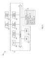
- FIG. 1shows computer system 100 which includes host 101 , input device 102 , display device 104 and disk drive 106 .
- Computer system 100can be, for example, a cloud storage device, personal computer system, or other electronic device. In this regard, computer system 100 may be a stand-alone system or part of a network.
- Input device 102can be a keyboard, scroll wheel, or pointing device allowing a user of computer system 100 to enter information and commands to computer system 100 , or to allow a user to manipulate objects displayed on display device 104 .
- input device 102 and display device 104can be combined into a single component, such as a touch-screen that displays objects and receives user input.
- host 101includes central processing unit (CPU) 108 which can be implemented using one or more processors for executing instructions including a microcontroller, a Digital Signal Processor (DSP), an Application Specific Integrated Circuit (ASIC), a Field Programmable Gate Array (FPGA), hard-wired logic, analog circuitry and/or a combination thereof.
- CPU 108interfaces with host bus 112 .
- Also interfacing with host bus 112are random access memory (RAM) 110 , input interface 114 for input device 102 , display interface 116 for display device 104 , read only memory (ROM) 118 , network interface 120 and disk drive 106 .
- RAMrandom access memory
- RAM 110interfaces with host bus 112 so as to provide information stored in RAM 110 to CPU 108 during execution of instructions in software programs such as operating system 10 , application programs 12 , and device drivers 16 . More specifically, CPU 108 first loads computer-executable instructions from disk drive 106 or another storage device into a region of RAM 110 . CPU 108 can then execute the stored process instructions from RAM 110 . Data such as data to be written to disk drive 106 or data read from disk drive 106 can be stored in RAM 110 so that the data can be accessed by CPU 108 during execution of software programs to the extent that such software programs have a need to access and/or modify the data.
- disk drive 106includes application programs 12 , which can include, for example, a word processing program or a multimedia program.
- disk drive 106includes other files 14 and device drivers 16 for software interfaces to devices such as input device 102 , display device 104 and/or disk drive 106 .
- FIG. 2illustrates a block diagram of disk drive 106 according to one example embodiment.
- disk drive 106includes rotating magnetic disk 200 and head 128 connected to the distal end of actuator 130 .
- Disk drive 106also includes a spindle motor (not shown) for rotating disk 200 .
- Actuator 130is pivoted about actuator pivot 134 by voice coil motor (VCM) 132 .
- VCMvoice coil motor
- Actuator pivot 134includes a track of pivot ball bearings (not shown) that are lubricated with grease to provide smooth movement of actuator 130 about actuator pivot 134 .
- disk drive 106includes controller 122 which can perform various operations of disk drive 106 described herein.
- Disk drive 106also includes memory 124 and host interface 101 .
- Memory 124can include a volatile memory, such as DRAM, and/or a non-volatile memory for storing data.
- Data stored in memory 124includes data read from disk 200 , data to be written to disk 200 , or instructions for controlling disk drive 106 , such as instructions for performing processes such as the grease wear leveling processes described below.
- Controller 122can be implemented using one or more processors for executing instructions and can include a microcontroller, a Digital Signal Processor (DSP), an Application Specific Integrated Circuit (ASIC), a Field Programmable Gate Array (FPGA), hard-wired logic, analog circuitry and/or a combination thereof.
- DSPDigital Signal Processor
- ASICApplication Specific Integrated Circuit
- FPGAField Programmable Gate Array
- Host interface 126is configured to interface disk drive 106 with host 101 and may interface according to the serial advanced technology attachment (SATA) standard or other standards such as serial attached SCSI (SAS). As will be appreciated by those of ordinary skill in the art, host interface 126 can be included as part of controller 122 .
- SATAserial advanced technology attachment
- SASserial attached SCSI
- Disk 200comprises a number of radial spaced, concentric tracks 210 , which may be grouped together into zones of tracks. Each track 210 is divided into a number of sectors that are spaced circumferentially along track 210 . The sectors may be used to store user data and/or other information. Disk 200 also includes a plurality of angularly spaced servo wedges 220 0 - 220 N , each of which may include embedded servo information that can be read from disk 200 by head 128 to determine the position of head 128 over disk 200 .
- each servo wedge 220 0 - 220 Nmay include a pattern of alternating magnetic transitions (servo burst), which may be read from disk 200 by head 128 and processed by controller 122 to estimate the position of head 128 relative to disk 200 .
- the angular spacing between servo wedges 220 0 - 220 Nmay be uniform, as shown in the example of FIG. 2 .
- controller 122writes data to and reads data from disk 200 as part of a seek operation in response to commands from host 101 received via host interface 126 .
- controller 122receives a write command from host 101 with data to be written to disk 200
- controller 122temporarily holds the received data in memory 124 .
- controller 122positions head 128 on disk 200 by sending VCM control signal 20 (e.g., control current) to VCM 132 .
- VCM control signal 20e.g., control current
- Controller 122positions head 128 based on position information read from one or more servo wedges 220 0 - 220 N .
- Controller 122processes data to be written to disk 200 into write signal 22 , which is output to head 128 .
- a write element (not shown) of head 128converts write signal 22 into a magnetic field that magnetizes the surface of disk 200 based upon write signal 22 , thereby magnetically writing data to disk 200 .
- Controller 122may notify host 101 via host interface 126 after data for the write command has been successfully written to disk 200 .
- controller 122When controller 122 receives a read command from host 101 , requesting data written on disk 200 , controller 122 positions head 128 on disk 200 by sending VCM control signal 20 to VCM 132 . A read element (not shown) of head 128 generates read signal 22 based upon the magnetization of the disk surface under head 128 , and controller 122 processes read signal 22 into data.
- disk 200can include a relatively high number of tracks 210 on the surface of disk 200 .
- grease buildup in actuator pivot 134can occur due to prolonged limited motion of actuator 130 during seek operations. This prolonged limited motion can result from repeated accessing of data confined within a small area of disk 200 .
- disk drive 106is capable of performing a grease wear leveling process to reduce the effects of grease build up.
- the grease wear leveling processcan include performing a predetermined number of full stroke seek (FSS) operations after a certain number of seek operations has been performed.
- FSSfull stroke seek
- a FSS operationincludes moving head 128 through a substantially wide range of motion about actuator pivot 134 .
- One approach disclosed hereinis to reduce delays in command completion time by spreading out a predetermined number of FSS operations across a limited number of seek operations when disk drive 106 is in an otherwise idle state. In this regard, it may be necessary to perform multiple FSS operations within a short period of time to effectively smooth out the grease bump. However, until the short amount of time expires, the partial number of completed FSS operations can be counted toward the predetermined number of FSS operations for smoothing out the grease bump.
- the window of seek operations within which to perform the predetermined number of FSS operationscan adjust or slide so that the predetermined number of FSS operations are performed within a certain number of interval seek operations.
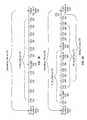
- FIGS. 3A to 3Cillustrate examples of using a sliding window for performing a predetermined number of FSS operations in a grease wear leveling process.
- the grease wear leveling processis initiated after a count of seek operations for disk drive 106 exceeds a threshold number of seek operations 310 .
- the threshold number of seek operations 310can vary depending upon design considerations of disk drive 106 , such as the quality of grease used in actuator pivot 134 or an average seek range for actuator 130 . For example, higher qualities of grease or a typically wider seek range may allow for a higher threshold number of seek operations.
- the threshold number of seek operations 310can be one million seek operations.
- the threshold number of seek operations 310may vary over the life of disk drive 106 depending upon a duty cycle of disk drive 106 or an age of disk drive 106 . In one such example, the threshold number of seek operations may lower over time to compensate for degradation of grease in actuator pivot 134 .
- the threshold for triggering the grease wear leveling processmay not be a threshold number of seek operations, but rather, may include other threshold criteria, such as an elapsed time since a previous grease wear leveling process, a first powering-up of disk drive 106 , or a specific command from host 101 .
- the threshold number of seek operations 310also begins cancellation period 338 , during which FSS operations can be cancelled or preempted by certain host commands, such as a read or write command.
- certain host commandssuch as a read or write command.
- the FSS operations initiated during cancellation period 338are performed when disk drive 106 is in an otherwise idle state so as to reduce the effect of the grease wear leveling process on the command completion time.
- Cancellation period 338includes a range of interval seeks (not shown) between the threshold number of seek operations 310 and a critical number of seek operations 334 .
- the threshold number of seek operations 310is one million seek operations
- the critical number of seek operations 334can be, for example, 1.1 million seek operations.
- the critical number of seek operations 334may represent a point at which grease buildup can begin to hinder the performance of disk drive 106 .
- disk drive 106completes cancellable FSS operations 312 , 314 , 316 , 318 , 322 , 324 , 326 , 328 , 330 and 332 within sliding window 336 .
- Cancelled FSS operation 320is a FSS operation that was begun, but was cancelled before completion due to a conflicting host command.
- a sliding windowis based on a number of interval seek operations performed since a previously performed FSS operation.
- a goal of using the sliding windowis to ensure that a predetermined number of FSS operations are completed within a certain time period, which in this case is measured by the number of interval seek operations performed since performance of a “first” FSS operation that triggered the start of the sliding window.
- sliding window 336can be the time it takes for 2,000 interval seek operations to be performed or the time it takes for the predetermined number of FSS operations (e.g., 10) to be performed, whichever occurs first.
- sliding window 336begins with FSS operation 312 and does not reach the full number of interval seek operations (e.g., 2,000) since the predetermined number of FSS operations (10 FSS operations in this example) is performed within sliding window 336 .
- the count of seek operations and the count of FSS operationsare reset and the grease wear leveling process ends.
- the predetermined number of FSS operations in the examples of FIGS. 3A to 3Care 10 FSS operations. However, as understood by those of ordinary skill in the art, the predetermined number of FSS operations can vary based on design considerations such as grease quality or an average seek range of motion for actuator 130 .
- the example of FIG. 3Balso includes threshold number of seek operations 310 , critical number of seek operations 334 , and cancellation period 338 .
- the predetermined number of FSS operations(10) are not performed within a first sliding window (i.e., sliding window 372 ). More specifically, sliding window 372 begins with cancellable FSS operation 342 . The next FSS operation, FSS operation 344 , is then cancelled and FSS operations 346 , 348 , 350 , 352 , and 354 are then completed. FSS operation 356 is cancelled and the number of interval seek operations for sliding window 372 is reached before the predetermined number of 10 FSS operations. In this case, only six FSS operations are completed within sliding window 372 .
- sliding window 374begins at the next completed FSS operation following the first FSS operation 342 of first sliding window 372 . As shown in FIG. 3B , sliding window 374 therefore begins at FSS 346 and the count of FSS operations is adjusted based on the most recently completed FSS operation within sliding window 372 , which is FSS operation 354 . At this point, the count of FSS operations for new sliding window 374 is five since the most recently completed FSS operation is the fifth completed FSS operation of sliding window 374 .
- the new sliding windowmay start at a different FSS operation, such as FSS operation 348 , if starting the new sliding window at FSS operation 346 would otherwise result in the limited number of interval seek operations having been already exceeded. In other situations, the new sliding window may not begin until a next FSS operation is completed if no previous FSS operations have been completed.
- the count of FSS operationscan be adjusted such that the count of FSS operations equals the number of completed FSS operations performed within the limited number of interval number of seek operations before the most recently completed FSS operation.
- the count of FSS operationscan be determined based on the number of FSS operations completed within 2,000 interval seeks before FSS operation 354 . In situations where there have not been any previously completed FSS operations within the limited number of interval seek operations, a new sliding window can begin with the next completed FSS operation.
- new sliding window 376begins at completed FSS operation 348 and ends at completed FSS operation 370 for a total of ten FSS operations completed (i.e., FSS operations 348 , 350 , 352 , 354 , 360 , 362 , 364 , 366 , 368 , and 370 ) within sliding window 376 , with FSS operations 356 and 358 having been cancelled.
- the grease wear leveling processends after completion of FSS operation 370 since the predetermined number of FSS operations has been performed within sliding window 376 .
- the count of seek operations and FSS operationsare also reset. Although for illustration purposes there are multiple sliding windows depicted, in one embodiment the implementation may involve a single sliding window that is reset according to the guidelines discussed above and thus “slides” along the timeline to account for the number of interval seek and/or FSS operations.
- FIG. 3Cillustrates an example where not all of the predetermined number of FSS operations are completed within cancellation period 338 .
- sliding window 399begins with cancellable FSS operation 378 and ends with non-cancellable FSS operation 398 .
- FSS operations 378 , 380 , 382 , 384 , 386 , 388 , and 390are cancellable since they occur within cancellation period 338 .
- non-cancellable FSS operations 392 and 394are performed in immediate succession. Unlike the FSS operations in cancellation period 338 , FSS operations 392 and 394 cannot be preempted or cancelled by a host command.
- two non-cancellable FSS operationsare performed in succession and are followed by other non-cancellable FSS operations as required to reach the predetermined number of FSS operations within sliding window 399 .
- Those of ordinary skill in the artwill appreciate that other numbers of non-cancellable FSS operations can be performed in succession or that individual non-cancellable FSS operations can performed throughout a period following cancellation period 338 .
- other embodimentscan have three non-cancellable FSS operations performed in succession.
- FSS operation 396is completed when disk drive 106 is in an idle state.
- FSS operation 396is cancellable, however, FSS operation 396 can be non-cancellable in other embodiments.
- FSS operation 396occurs when disk drive 106 is in an idle state, FSS operation 396 in a different embodiment can occur after a set period of time or after a certain number of seek operations from non-cancellable FSS operation 394 .
- disk drive 106After completion of cancellable FSS operation 396 , disk drive 106 performs non-cancellable FSS operation 398 , which can otherwise be a first non-cancellable FSS operation of a second set of two non-cancellable FSS operations. However, in the example of FIG. 3C , the predetermined number of FSS operations is reached within sliding window 399 after completion of non-cancellable FSS operation 398 . The count of seek operations and the count of FSS operations is then reset, and the grease wear leveling process ends.
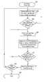
- FIG. 4is a flowchart including an example grease wear leveling process performed by disk drive 106 . As shown in FIG. 4 , the process starts upon power-up of disk drive 106 in block 402 . In block 404 , controller 122 controls actuator 130 via VCM 132 and actuator pivot 134 to perform seek operations based on commands received from host 101 . In addition, controller 122 maintains a count of performed seek operations in memory 124 .
- controller 122determines whether the count of seek operations exceeds a threshold number of seek operations. If it is determined the count of seek operations does not exceed the threshold number of seek operations, disk drive 106 continues to perform seek operations and maintain the count of seek operations in block 404 . If it is determined in block 406 that the count of seek operations exceeds the threshold number of seek operations, controller 122 controls actuator 130 to perform at least one FSS operation in block 408 .
- the at least one FSS operationcan be a cancellable FSS operation or a non-cancellable FSS operation.
- controller 122may wait until disk drive 106 is in an idle state before performing the at least one FSS operation in block 408 to allow disk drive 106 to complete received host commands.
- controller 122adjusts a count of completed FSS operations stored in memory 124 based on at least whether the FSS operation of block 408 was performed within a sliding time window of interval seek operations. As discussed above with reference to FIGS. 3A to 3C , whether the FSS operation of block 408 was performed within a current sliding window can be determined from the number of interval seek operations performed since a previous FSS operation. In some cases, the FSS operation performed in block 408 can be counted as the first FSS operation if there are no previously completed FSS operations within a limited number of interval seek operations.
- the interval number of seek operationscan be, for example, 2,000 seek operations.
- the count of FSS operationscan be adjusted to equal the number of completed FSS operations within 2,000 seek operations of the FSS operation performed in block 408 .
- controller 122determines whether the count of FSS operations has reached a predetermined number of completed FSS operations for the grease wear leveling process. If controller 122 determines that the count of FSS operations has not completed the predetermined number of FSS operations, the grease wear leveling process returns to block 408 to perform at least one FSS operation. If controller 122 determines in block 412 that the count of completed FSS operations has reached the predetermined number, controller 122 resets the count of seeks and the count of FSS operations in block 414 .
- FIG. 5Ais a flowchart of an example grease wear leveling process including a cancellable period and critical criteria for performing non-cancellable FSS operations.
- the processbegins in block 422 when the count of seek operations exceeds the threshold number of seek operations and disk drive 106 is in an idle state, such as when disk drive 106 does not have any host commands to perform.
- controller 122sets the count of FSS operations to zero to initialize the count of FSS operations.
- controller 122determines whether a critical criteria has been satisfied.
- the critical criteriacan be, for example, whether a second threshold number of seek operations has been exceeded or whether a certain amount of time has elapsed since the start of a grease wear leveling process. If controller 122 determines that the critical criteria has been satisfied in block 426 , the process proceeds to the sub-process of FIG. 5B for performing non-cancellable FSS operations. The sub-process of FIG. 5B is described in more detail below.
- controller 122determines that the critical criteria has not been satisfied, controller 122 controls actuator 130 to begin a cancellable FSS operation in block 428 . If the FSS operation begun in block 428 is cancelled in block 430 , the process returns to block 426 to determine whether the critical criteria has been satisfied.
- the FSS operation of block 428can be cancelled, for example, if disk drive 106 receives a host read or write command while disk drive 106 is performing the FSS operation. After cancellation of the FSS operation in block 430 , disk drive 106 can continue servicing successive host commands before returning to block 428 when disk drive 106 becomes idle.
- controller 122determines in block 432 whether the completed FSS operation occurred within the sliding window of seeks, as described with reference to FIGS. 3A to 3C . If not, controller 122 adjusts the sliding window so that the completed FSS operation begun in block 428 is within the number of interval seeks for the sliding window. In one example, this may mean that a new sliding window begins with the completed FSS operation begun in block 428 . In another example, a new sliding window can begin with a previously completed FSS operation that is within the number of interval seeks from the completed FSS operation begun in block 428 . In block 438 , controller 122 sets the count of FSS operations to the number of completed FSS operations in the new sliding window. The process then returns to block 426 to determine whether the critical criteria has been satisfied.
- controller 122determines in block 432 that the FSS operation begun in block 428 completed within the sliding window. Controller 122 increments the count of FSS operations in block 434 . Controller 122 determines in block 440 whether the count of FSS operations is less than the predetermined number of FSS operations. If so, the process returns to block 426 to determine whether the critical criteria has been satisfied. On the other hand, if it is determined in block 440 that the count of FSS operations is not less than the predetermined number of FSS operations, the count of seeks and the count of FSS operations are reset in block 442 . The grease wear leveling process then ends in block 444 .
- the flow chart of FIG. 5Bdepicts a sub-process of the grease wear leveling process of FIG. 5A . If controller 122 determines in block 426 of FIG. 5A that the critical criteria has been satisfied, the grease wear leveling process proceeds to block 450 of FIG. 5B where controller 122 calculates the remaining number of FSS operations to reach the predetermined number of FSS operations within the current sliding window. In block 452 , controller 122 checks whether the remaining number of FSS operations calculated in block 450 is less than or equal to one. If so, controller 122 controls actuator 130 to perform the remaining number of non-cancellable FSS operations in block 454 . The process then returns to block 442 in FIG. 5A to reset the count of seeks and the count of FSS operations.
- controller 122determines in block 452 that the remaining number of FSS operations to reach the predetermined number of FSS operations is greater than one, controller 122 controls actuator 130 in block 456 to perform a set of non-cancellable FSS operations.
- actuator 130may perform a set of two non-cancellable FSS operations in succession.
- the number of non-cancellable FSS operations ordinarily performedis greater than the remaining number of FSS operations needed to reach the predetermined number of FSS operations, only the remaining number of FSS operations are performed in block 456 .
- controller 122determines whether disk drive 106 is in an idle state. If so, the sub-process returns to block 450 to calculate the remaining number of FSS operations to reach the predetermined number of FSS operations. On the other hand, if disk drive 106 is not in an idle state, controller 122 determines whether the end of the sliding window is near. For example, controller 122 may determine that the end of the sliding window is near if 10% or less of the number of interval seeks for the sliding window remain. Other embodiments may use a different number of remaining interval seeks to determine whether the end of the sliding window is approaching.
- the sub-processreturns to block 458 to determine whether disk drive 106 is in an idle state. If it is determined in block 460 that the end of the sliding window is approaching, the sub-process returns to block 450 to calculate the remaining number of FSS operations to perform in the sliding window.
- DSPdigital signal processor
- ASICapplication specific integrated circuit
- FPGAfield programmable gate array
- a general purpose processormay be a microprocessor, but in the alternative, the processor may be any conventional processor, controller, microcontroller, or state machine.
- a processormay also be implemented as a combination of computing devices, e.g., a combination of a DSP and a microprocessor, a plurality of microprocessors, one or more microprocessors in conjunction with a DSP core, or any other such configuration.
- a software modulemay reside in RAM memory, flash memory, ROM memory, EPROM memory, EEPROM memory, registers, hard disk, a removable disk, a CD-ROM, or any other form of storage medium known in the art.
- An exemplary storage mediumis coupled to the processor such that the processor can read information from, and write information to, the storage medium. In the alternative, the storage medium may be integral to the processor.
- the processor and the storage mediummay reside in an Application Specific Integrated Circuit (ASIC).
- ASICApplication Specific Integrated Circuit
Landscapes
- Moving Of Head For Track Selection And Changing (AREA)
Abstract
Description
Claims (20)
Priority Applications (1)
| Application Number | Priority Date | Filing Date | Title |
|---|---|---|---|
| US13/627,952US8780478B1 (en) | 2012-09-26 | 2012-09-26 | Grease wear leveling for a disk drive |
Applications Claiming Priority (1)
| Application Number | Priority Date | Filing Date | Title |
|---|---|---|---|
| US13/627,952US8780478B1 (en) | 2012-09-26 | 2012-09-26 | Grease wear leveling for a disk drive |
Publications (1)
| Publication Number | Publication Date |
|---|---|
| US8780478B1true US8780478B1 (en) | 2014-07-15 |
Family
ID=51135694
Family Applications (1)
| Application Number | Title | Priority Date | Filing Date |
|---|---|---|---|
| US13/627,952Expired - Fee RelatedUS8780478B1 (en) | 2012-09-26 | 2012-09-26 | Grease wear leveling for a disk drive |
Country Status (1)
| Country | Link |
|---|---|
| US (1) | US8780478B1 (en) |
Cited By (53)
| Publication number | Priority date | Publication date | Assignee | Title |
|---|---|---|---|---|
| US8902529B1 (en) | 2012-11-20 | 2014-12-02 | Western Digital Technologies, Inc. | Dual frequency crystal oscillator |
| US8914625B1 (en) | 2009-07-31 | 2014-12-16 | Western Digital Technologies, Inc. | Automatically configuring a web browser file when booting an operating system from a data storage device |
| US8953269B1 (en) | 2014-07-18 | 2015-02-10 | Western Digital Technologies, Inc. | Management of data objects in a data object zone |
| US8959281B1 (en) | 2012-11-09 | 2015-02-17 | Western Digital Technologies, Inc. | Data management for a storage device |
| US8990493B1 (en) | 2011-06-30 | 2015-03-24 | Western Digital Technologies, Inc. | Method and apparatus for performing force unit access writes on a disk |
| US8996839B1 (en) | 2012-01-23 | 2015-03-31 | Western Digital Technologies, Inc. | Data storage device aligning partition to boundary of sector when partition offset correlates with offset of write commands |
| US9009358B1 (en) | 2008-09-23 | 2015-04-14 | Western Digital Technologies, Inc. | Configuring a data storage device with a parameter file interlocked with configuration code |
| US9025270B1 (en) | 2013-09-17 | 2015-05-05 | Western Digital Technologies, Inc. | Electronic system with current conservation mechanism and method of operation thereof |
| US9049471B2 (en) | 2001-10-17 | 2015-06-02 | Keen Personal Media, Inc. | Personal video recorder for inserting a stored advertisement into a displayed broadcast stream |
| US9060420B2 (en) | 2007-11-01 | 2015-06-16 | Western Digitial Technologies, Inc. | Method of manufacturing a double sided flex circuit for a disk drive wherein a first side lead provides an etching mask for a second side lead |
| US9063838B1 (en) | 2012-01-23 | 2015-06-23 | Western Digital Technologies, Inc. | Data storage device shifting data chunks of alignment zone relative to sector boundaries |
| US9075714B1 (en) | 2014-05-13 | 2015-07-07 | Western Digital Technologies, Inc. | Electronic system with data management mechanism and method of operation thereof |
| US9123382B1 (en) | 2014-10-28 | 2015-09-01 | Western Digital Technologies, Inc. | Non-volatile caching for sequence of data |
| US9128820B1 (en) | 2012-06-18 | 2015-09-08 | Western Digital Technologies, Inc. | File management among different zones of storage media |
| US9129628B1 (en) | 2014-10-23 | 2015-09-08 | Western Digital Technologies, Inc. | Data management for data storage device with different track density regions |
| US9135205B1 (en) | 2013-05-01 | 2015-09-15 | Western Digital Technologies, Inc. | Data storage assembly for archive cold storage |
| US9153287B1 (en) | 2013-05-13 | 2015-10-06 | Western Digital Technologies, Inc. | Data access for shingled magnetic recording media |
| US9158722B1 (en) | 2011-11-02 | 2015-10-13 | Western Digital Technologies, Inc. | Data storage device to communicate with a host in a SATA or a USB mode |
| US9189392B1 (en) | 2011-06-30 | 2015-11-17 | Western Digital Technologies, Inc. | Opportunistic defragmentation during garbage collection |
| US9196302B1 (en) | 2015-03-18 | 2015-11-24 | Western Digital Technologies, Inc. | Electronic system with media maintenance mechanism and method of operation thereof |
| US9208808B1 (en) | 2014-04-22 | 2015-12-08 | Western Digital Technologies, Inc. | Electronic system with unload management mechanism and method of operation thereof |
| US9236086B1 (en) | 2014-10-15 | 2016-01-12 | Western Digital Technologies, Inc. | Methods for reducing operational latency of data storage systems |
| US9245558B1 (en) | 2014-05-09 | 2016-01-26 | Western Digital Technologies, Inc. | Electronic system with data management mechanism and method of operation thereof |
| US9257143B1 (en) | 2014-12-23 | 2016-02-09 | Western Digital Technologies, Inc. | Precautionary measures for data storage device environmental conditions |
| US9263088B2 (en) | 2014-03-21 | 2016-02-16 | Western Digital Technologies, Inc. | Data management for a data storage device using a last resort zone |
| US9268649B1 (en) | 2011-06-23 | 2016-02-23 | Western Digital Technologies, Inc. | Disk drive with recent write streams list for data refresh determination |
| US9268499B1 (en) | 2010-08-13 | 2016-02-23 | Western Digital Technologies, Inc. | Hybrid drive migrating high workload data from disk to non-volatile semiconductor memory |
| US9269393B1 (en) | 2014-12-08 | 2016-02-23 | Western Digital Technologies, Inc. | Electronic system with data refresh mechanism and method of operation thereof |
| US9311939B1 (en) | 2014-12-23 | 2016-04-12 | Western Digital Technologies, Inc. | Write-through media caching |
| US9330715B1 (en) | 2010-03-22 | 2016-05-03 | Western Digital Technologies, Inc. | Mapping of shingled magnetic recording media |
| CN105654966A (en)* | 2014-10-17 | 2016-06-08 | Hgst荷兰公司 | Self-cleaning recording head based on actuator seek profile |
| US9383923B1 (en) | 2012-10-18 | 2016-07-05 | Western Digital Technologies, Inc. | Write pointer management for a disk drive |
| US9424864B2 (en) | 2014-07-02 | 2016-08-23 | Western Digital Technologies, Inc. | Data management for a data storage device with zone relocation |
| US9437242B1 (en) | 2015-09-14 | 2016-09-06 | Western Digital Technologies, Inc. | Data storage device employing different frequency preambles in adjacent data tracks |
| US9466318B2 (en) | 2014-12-24 | 2016-10-11 | Western Digital Technologies, Inc. | Allowing fast data zone switches on data storage devices |
| US9466321B1 (en) | 2015-06-05 | 2016-10-11 | Western Digital Technologies, Inc. | Angular position tracking of data accesses to mitigate risk of data loss |
| US9501393B2 (en) | 2014-01-27 | 2016-11-22 | Western Digital Technologies, Inc. | Data storage system garbage collection based on at least one attribute |
| US9588898B1 (en) | 2015-06-02 | 2017-03-07 | Western Digital Technologies, Inc. | Fullness control for media-based cache operating in a steady state |
| US9600205B1 (en) | 2014-09-22 | 2017-03-21 | Western Digital Technologies, Inc. | Power aware power safe write buffer |
| US9632711B1 (en) | 2014-04-07 | 2017-04-25 | Western Digital Technologies, Inc. | Processing flush requests by utilizing storage system write notifications |
| US9639287B1 (en) | 2015-06-29 | 2017-05-02 | Western Digital Technologies, Inc. | Write command reporting |
| US9645752B1 (en) | 2014-04-07 | 2017-05-09 | Western Digital Technologies, Inc. | Identification of data committed to non-volatile memory by use of notification commands |
| US9672107B1 (en) | 2015-02-11 | 2017-06-06 | Western Digital Technologies, Inc. | Data protection for a data storage device |
| US9842622B1 (en) | 2014-12-23 | 2017-12-12 | Western Digital Technologies, Inc. | Data storage device having improved read failure tolerance |
| US9864529B1 (en) | 2014-01-27 | 2018-01-09 | Western Digital Technologies, Inc. | Host compatibility for host managed storage media |
| US9870281B1 (en) | 2015-03-20 | 2018-01-16 | Western Digital Technologies, Inc. | Power loss mitigation for data storage device |
| US9875055B1 (en) | 2014-08-04 | 2018-01-23 | Western Digital Technologies, Inc. | Check-pointing of metadata |
| US9933955B1 (en) | 2015-03-05 | 2018-04-03 | Western Digital Technologies, Inc. | Power safe write buffer for data storage device |
| US9952950B1 (en) | 2014-09-08 | 2018-04-24 | Western Digital Technologies, Inc. | Data management in RAID environment |
| US9959052B1 (en) | 2015-09-17 | 2018-05-01 | Western Digital Technologies, Inc. | Media based cache for data storage device |
| US10282371B1 (en) | 2014-12-02 | 2019-05-07 | Western Digital Technologies, Inc. | Object storage device with probabilistic data structure |
| US10282096B1 (en) | 2014-12-17 | 2019-05-07 | Western Digital Technologies, Inc. | Identification of data with predetermined data pattern |
| US10365836B1 (en) | 2015-01-27 | 2019-07-30 | Western Digital Technologies, Inc. | Electronic system with declustered data protection by parity based on reliability and method of operation thereof |
Citations (7)
| Publication number | Priority date | Publication date | Assignee | Title |
|---|---|---|---|---|
| US5307489A (en)* | 1991-03-26 | 1994-04-26 | Nec Corporation | Seek system for a magnetic disk apparatus |
| US5491816A (en)* | 1990-09-20 | 1996-02-13 | Fujitsu Limited | Input/ouput controller providing preventive maintenance information regarding a spare I/O unit |
| US5615368A (en)* | 1992-08-18 | 1997-03-25 | Nec Corporation | System having table storing plurality of optimal patrol seek schemes for respective disk drives and executing associated scheme based upon inputted disk device name |
| US20020196574A1 (en) | 2001-06-22 | 2002-12-26 | International Business Machines Corporation | System and method for reducing the accumulation of actuator bearing grease in hard disk drives |
| US20060092549A1 (en) | 2004-11-02 | 2006-05-04 | Hitachi Global Storage Technologies Netherlands B.V. | Magnetic disk drive and method for executing seek operation |
| US20080239545A1 (en) | 2007-03-28 | 2008-10-02 | Daryl Carvis Cromer | System and Method to Avoid Disk Lube Pooling |
| US20100134912A1 (en) | 2007-08-22 | 2010-06-03 | Willliam Charles Koester | Lubricant distribution in hard disk drives used for digital video recorders |
- 2012
- 2012-09-26USUS13/627,952patent/US8780478B1/ennot_activeExpired - Fee Related
Patent Citations (11)
| Publication number | Priority date | Publication date | Assignee | Title |
|---|---|---|---|---|
| US5491816A (en)* | 1990-09-20 | 1996-02-13 | Fujitsu Limited | Input/ouput controller providing preventive maintenance information regarding a spare I/O unit |
| US5826003A (en)* | 1990-09-20 | 1998-10-20 | Fujitsu Limited | Input/output controller providing preventive maintenance information regarding a spare I/O unit |
| US5307489A (en)* | 1991-03-26 | 1994-04-26 | Nec Corporation | Seek system for a magnetic disk apparatus |
| US5615368A (en)* | 1992-08-18 | 1997-03-25 | Nec Corporation | System having table storing plurality of optimal patrol seek schemes for respective disk drives and executing associated scheme based upon inputted disk device name |
| US20020196574A1 (en) | 2001-06-22 | 2002-12-26 | International Business Machines Corporation | System and method for reducing the accumulation of actuator bearing grease in hard disk drives |
| US6754024B2 (en) | 2001-06-22 | 2004-06-22 | International Business Machines Corporation | System and method for reducing the accumulation of actuator bearing grease in hard disk drives |
| US20060092549A1 (en) | 2004-11-02 | 2006-05-04 | Hitachi Global Storage Technologies Netherlands B.V. | Magnetic disk drive and method for executing seek operation |
| US7271976B2 (en) | 2004-11-02 | 2007-09-18 | Hitachi Global Storage Technologies Netherlands B.V. | Magnetic disk drive and method for seek operations with reduced noise |
| US20080239545A1 (en) | 2007-03-28 | 2008-10-02 | Daryl Carvis Cromer | System and Method to Avoid Disk Lube Pooling |
| US7817370B2 (en) | 2007-03-28 | 2010-10-19 | Lenovo (Singapore) Pte. Ltd. | System and method to avoid disk lube pooling |
| US20100134912A1 (en) | 2007-08-22 | 2010-06-03 | Willliam Charles Koester | Lubricant distribution in hard disk drives used for digital video recorders |
Cited By (59)
| Publication number | Priority date | Publication date | Assignee | Title |
|---|---|---|---|---|
| US9049471B2 (en) | 2001-10-17 | 2015-06-02 | Keen Personal Media, Inc. | Personal video recorder for inserting a stored advertisement into a displayed broadcast stream |
| US9060420B2 (en) | 2007-11-01 | 2015-06-16 | Western Digitial Technologies, Inc. | Method of manufacturing a double sided flex circuit for a disk drive wherein a first side lead provides an etching mask for a second side lead |
| US9009358B1 (en) | 2008-09-23 | 2015-04-14 | Western Digital Technologies, Inc. | Configuring a data storage device with a parameter file interlocked with configuration code |
| US8914625B1 (en) | 2009-07-31 | 2014-12-16 | Western Digital Technologies, Inc. | Automatically configuring a web browser file when booting an operating system from a data storage device |
| US9330715B1 (en) | 2010-03-22 | 2016-05-03 | Western Digital Technologies, Inc. | Mapping of shingled magnetic recording media |
| US9268499B1 (en) | 2010-08-13 | 2016-02-23 | Western Digital Technologies, Inc. | Hybrid drive migrating high workload data from disk to non-volatile semiconductor memory |
| US9268649B1 (en) | 2011-06-23 | 2016-02-23 | Western Digital Technologies, Inc. | Disk drive with recent write streams list for data refresh determination |
| US8990493B1 (en) | 2011-06-30 | 2015-03-24 | Western Digital Technologies, Inc. | Method and apparatus for performing force unit access writes on a disk |
| US9189392B1 (en) | 2011-06-30 | 2015-11-17 | Western Digital Technologies, Inc. | Opportunistic defragmentation during garbage collection |
| US9158722B1 (en) | 2011-11-02 | 2015-10-13 | Western Digital Technologies, Inc. | Data storage device to communicate with a host in a SATA or a USB mode |
| US8996839B1 (en) | 2012-01-23 | 2015-03-31 | Western Digital Technologies, Inc. | Data storage device aligning partition to boundary of sector when partition offset correlates with offset of write commands |
| US9063838B1 (en) | 2012-01-23 | 2015-06-23 | Western Digital Technologies, Inc. | Data storage device shifting data chunks of alignment zone relative to sector boundaries |
| US9128820B1 (en) | 2012-06-18 | 2015-09-08 | Western Digital Technologies, Inc. | File management among different zones of storage media |
| US9477681B2 (en) | 2012-06-18 | 2016-10-25 | Western Digital Technologies, Inc. | File management among different zones of storage media |
| US9383923B1 (en) | 2012-10-18 | 2016-07-05 | Western Digital Technologies, Inc. | Write pointer management for a disk drive |
| US8959281B1 (en) | 2012-11-09 | 2015-02-17 | Western Digital Technologies, Inc. | Data management for a storage device |
| US8902529B1 (en) | 2012-11-20 | 2014-12-02 | Western Digital Technologies, Inc. | Dual frequency crystal oscillator |
| US9135205B1 (en) | 2013-05-01 | 2015-09-15 | Western Digital Technologies, Inc. | Data storage assembly for archive cold storage |
| US9153287B1 (en) | 2013-05-13 | 2015-10-06 | Western Digital Technologies, Inc. | Data access for shingled magnetic recording media |
| US9025270B1 (en) | 2013-09-17 | 2015-05-05 | Western Digital Technologies, Inc. | Electronic system with current conservation mechanism and method of operation thereof |
| US9864529B1 (en) | 2014-01-27 | 2018-01-09 | Western Digital Technologies, Inc. | Host compatibility for host managed storage media |
| US9501393B2 (en) | 2014-01-27 | 2016-11-22 | Western Digital Technologies, Inc. | Data storage system garbage collection based on at least one attribute |
| US10282130B2 (en) | 2014-01-27 | 2019-05-07 | Western Digital Technologies, Inc. | Coherency of data in data relocation |
| US9263088B2 (en) | 2014-03-21 | 2016-02-16 | Western Digital Technologies, Inc. | Data management for a data storage device using a last resort zone |
| US9632711B1 (en) | 2014-04-07 | 2017-04-25 | Western Digital Technologies, Inc. | Processing flush requests by utilizing storage system write notifications |
| US9645752B1 (en) | 2014-04-07 | 2017-05-09 | Western Digital Technologies, Inc. | Identification of data committed to non-volatile memory by use of notification commands |
| US10162534B1 (en) | 2014-04-07 | 2018-12-25 | Western Digital Technologies, Inc. | Ordering commitment of data from a data cache to nonvolatile memory using ordering commands |
| US9208808B1 (en) | 2014-04-22 | 2015-12-08 | Western Digital Technologies, Inc. | Electronic system with unload management mechanism and method of operation thereof |
| US9245558B1 (en) | 2014-05-09 | 2016-01-26 | Western Digital Technologies, Inc. | Electronic system with data management mechanism and method of operation thereof |
| US9075714B1 (en) | 2014-05-13 | 2015-07-07 | Western Digital Technologies, Inc. | Electronic system with data management mechanism and method of operation thereof |
| US9424864B2 (en) | 2014-07-02 | 2016-08-23 | Western Digital Technologies, Inc. | Data management for a data storage device with zone relocation |
| US8953269B1 (en) | 2014-07-18 | 2015-02-10 | Western Digital Technologies, Inc. | Management of data objects in a data object zone |
| US9875055B1 (en) | 2014-08-04 | 2018-01-23 | Western Digital Technologies, Inc. | Check-pointing of metadata |
| US9952950B1 (en) | 2014-09-08 | 2018-04-24 | Western Digital Technologies, Inc. | Data management in RAID environment |
| US10572358B1 (en) | 2014-09-08 | 2020-02-25 | Western Digital Technologies, Inc. | Data management in RAID environment |
| US9600205B1 (en) | 2014-09-22 | 2017-03-21 | Western Digital Technologies, Inc. | Power aware power safe write buffer |
| US9236086B1 (en) | 2014-10-15 | 2016-01-12 | Western Digital Technologies, Inc. | Methods for reducing operational latency of data storage systems |
| US9368137B2 (en)* | 2014-10-17 | 2016-06-14 | HGST Netherlands B.V. | Self-cleaning recording heads based on actuator seek profile |
| EP3010019A3 (en)* | 2014-10-17 | 2016-08-03 | HGST Netherlands B.V. | Self-cleaning recording heads based on actuator seek profile |
| CN105654966A (en)* | 2014-10-17 | 2016-06-08 | Hgst荷兰公司 | Self-cleaning recording head based on actuator seek profile |
| US9129628B1 (en) | 2014-10-23 | 2015-09-08 | Western Digital Technologies, Inc. | Data management for data storage device with different track density regions |
| US9123382B1 (en) | 2014-10-28 | 2015-09-01 | Western Digital Technologies, Inc. | Non-volatile caching for sequence of data |
| US10282371B1 (en) | 2014-12-02 | 2019-05-07 | Western Digital Technologies, Inc. | Object storage device with probabilistic data structure |
| US9269393B1 (en) | 2014-12-08 | 2016-02-23 | Western Digital Technologies, Inc. | Electronic system with data refresh mechanism and method of operation thereof |
| US10282096B1 (en) | 2014-12-17 | 2019-05-07 | Western Digital Technologies, Inc. | Identification of data with predetermined data pattern |
| US9311939B1 (en) | 2014-12-23 | 2016-04-12 | Western Digital Technologies, Inc. | Write-through media caching |
| US9257143B1 (en) | 2014-12-23 | 2016-02-09 | Western Digital Technologies, Inc. | Precautionary measures for data storage device environmental conditions |
| US9842622B1 (en) | 2014-12-23 | 2017-12-12 | Western Digital Technologies, Inc. | Data storage device having improved read failure tolerance |
| US9466318B2 (en) | 2014-12-24 | 2016-10-11 | Western Digital Technologies, Inc. | Allowing fast data zone switches on data storage devices |
| US10365836B1 (en) | 2015-01-27 | 2019-07-30 | Western Digital Technologies, Inc. | Electronic system with declustered data protection by parity based on reliability and method of operation thereof |
| US9672107B1 (en) | 2015-02-11 | 2017-06-06 | Western Digital Technologies, Inc. | Data protection for a data storage device |
| US9933955B1 (en) | 2015-03-05 | 2018-04-03 | Western Digital Technologies, Inc. | Power safe write buffer for data storage device |
| US9196302B1 (en) | 2015-03-18 | 2015-11-24 | Western Digital Technologies, Inc. | Electronic system with media maintenance mechanism and method of operation thereof |
| US9870281B1 (en) | 2015-03-20 | 2018-01-16 | Western Digital Technologies, Inc. | Power loss mitigation for data storage device |
| US9588898B1 (en) | 2015-06-02 | 2017-03-07 | Western Digital Technologies, Inc. | Fullness control for media-based cache operating in a steady state |
| US9466321B1 (en) | 2015-06-05 | 2016-10-11 | Western Digital Technologies, Inc. | Angular position tracking of data accesses to mitigate risk of data loss |
| US9639287B1 (en) | 2015-06-29 | 2017-05-02 | Western Digital Technologies, Inc. | Write command reporting |
| US9437242B1 (en) | 2015-09-14 | 2016-09-06 | Western Digital Technologies, Inc. | Data storage device employing different frequency preambles in adjacent data tracks |
| US9959052B1 (en) | 2015-09-17 | 2018-05-01 | Western Digital Technologies, Inc. | Media based cache for data storage device |
Similar Documents
| Publication | Publication Date | Title |
|---|---|---|
| US8780478B1 (en) | Grease wear leveling for a disk drive | |
| US8817413B1 (en) | Disk lubricant management in data storage device | |
| US8780479B1 (en) | Disk drive executing jerk seeks to rotate pivot ball bearings relative to races | |
| US7088538B1 (en) | Adaptively estimating a read access time to a second track based upon the binned radial position of the second track within a rotating media storage device | |
| US9141176B1 (en) | Power management for data storage device | |
| US9311939B1 (en) | Write-through media caching | |
| US8699159B1 (en) | Reducing effects of wide area track erasure in a disk drive | |
| US8068299B2 (en) | Disk drive device and data rewrite method thereof | |
| US9418699B1 (en) | Management of sequentially written data | |
| US9472222B2 (en) | Vibration mitigation for a data storage device | |
| US9026728B1 (en) | Disk drive applying feed-forward compensation when writing consecutive data tracks | |
| US11960760B2 (en) | Seek scheduling in a split actuator drive | |
| US10242704B2 (en) | Command clustering for data storage device | |
| US7483230B2 (en) | Write-current control chip and magnetic disk drive using the same | |
| US9269393B1 (en) | Electronic system with data refresh mechanism and method of operation thereof | |
| US11615811B2 (en) | Split actuator drive that limits slew rate of aggressor VCM to reduce victim disturbances | |
| KR20120039985A (en) | Method for processing read or write operation for recording media, parameter adjusting method in storage device, storage device, computer system and storage medium applying the same | |
| US8736994B2 (en) | Disk storage apparatus and write control method | |
| US11036436B2 (en) | Seek scheduling in a split actuator drive | |
| US8117491B2 (en) | Disk-drive device and method for error recovery thereof | |
| US7123435B1 (en) | Method and apparatus for overwriting data in a disk drive | |
| US9275667B1 (en) | Disk drive servo control system with low power consumption for long seeks | |
| US9070379B2 (en) | Data migration for data storage device | |
| US9047924B1 (en) | Magnetic disk device and method of data refresh processing | |
| US8909889B1 (en) | Method and apparatus for servicing host commands by a disk drive |
Legal Events
| Date | Code | Title | Description |
|---|---|---|---|
| AS | Assignment | Owner name:WESTERN DIGITAL TECHNOLOGIES, INC., CALIFORNIA Free format text:ASSIGNMENT OF ASSIGNORS INTEREST;ASSIGNORS:HUYNH, SANG;SMITH, KENNETH J.;LLOYD, JONATHAN C.;AND OTHERS;SIGNING DATES FROM 20120927 TO 20121008;REEL/FRAME:029090/0092 | |
| STCF | Information on status: patent grant | Free format text:PATENTED CASE | |
| CC | Certificate of correction | ||
| AS | Assignment | Owner name:U.S. BANK NATIONAL ASSOCIATION, AS COLLATERAL AGENT, CALIFORNIA Free format text:SECURITY AGREEMENT;ASSIGNOR:WESTERN DIGITAL TECHNOLOGIES, INC.;REEL/FRAME:038744/0281 Effective date:20160512 Owner name:JPMORGAN CHASE BANK, N.A., AS COLLATERAL AGENT, ILLINOIS Free format text:SECURITY AGREEMENT;ASSIGNOR:WESTERN DIGITAL TECHNOLOGIES, INC.;REEL/FRAME:038744/0481 Effective date:20160512 Owner name:JPMORGAN CHASE BANK, N.A., AS COLLATERAL AGENT, ILLINOIS Free format text:SECURITY AGREEMENT;ASSIGNOR:WESTERN DIGITAL TECHNOLOGIES, INC.;REEL/FRAME:038722/0229 Effective date:20160512 Owner name:JPMORGAN CHASE BANK, N.A., AS COLLATERAL AGENT, IL Free format text:SECURITY AGREEMENT;ASSIGNOR:WESTERN DIGITAL TECHNOLOGIES, INC.;REEL/FRAME:038722/0229 Effective date:20160512 Owner name:U.S. BANK NATIONAL ASSOCIATION, AS COLLATERAL AGEN Free format text:SECURITY AGREEMENT;ASSIGNOR:WESTERN DIGITAL TECHNOLOGIES, INC.;REEL/FRAME:038744/0281 Effective date:20160512 Owner name:JPMORGAN CHASE BANK, N.A., AS COLLATERAL AGENT, IL Free format text:SECURITY AGREEMENT;ASSIGNOR:WESTERN DIGITAL TECHNOLOGIES, INC.;REEL/FRAME:038744/0481 Effective date:20160512 | |
| MAFP | Maintenance fee payment | Free format text:PAYMENT OF MAINTENANCE FEE, 4TH YEAR, LARGE ENTITY (ORIGINAL EVENT CODE: M1551) Year of fee payment:4 | |
| AS | Assignment | Owner name:WESTERN DIGITAL TECHNOLOGIES, INC., CALIFORNIA Free format text:RELEASE BY SECURED PARTY;ASSIGNOR:U.S. BANK NATIONAL ASSOCIATION, AS COLLATERAL AGENT;REEL/FRAME:045501/0714 Effective date:20180227 | |
| AS | Assignment | Owner name:WESTERN DIGITAL TECHNOLOGIES, INC., CALIFORNIA Free format text:RELEASE OF SECURITY INTEREST AT REEL 038744 FRAME 0481;ASSIGNOR:JPMORGAN CHASE BANK, N.A.;REEL/FRAME:058982/0556 Effective date:20220203 | |
| FEPP | Fee payment procedure | Free format text:MAINTENANCE FEE REMINDER MAILED (ORIGINAL EVENT CODE: REM.); ENTITY STATUS OF PATENT OWNER: LARGE ENTITY | |
| LAPS | Lapse for failure to pay maintenance fees | Free format text:PATENT EXPIRED FOR FAILURE TO PAY MAINTENANCE FEES (ORIGINAL EVENT CODE: EXP.); ENTITY STATUS OF PATENT OWNER: LARGE ENTITY | |
| STCH | Information on status: patent discontinuation | Free format text:PATENT EXPIRED DUE TO NONPAYMENT OF MAINTENANCE FEES UNDER 37 CFR 1.362 | |
| FP | Lapsed due to failure to pay maintenance fee | Effective date:20220715 |