US8780282B2 - Vehicle entertainment system - Google Patents
Vehicle entertainment systemDownload PDFInfo
- Publication number
- US8780282B2 US8780282B2US12/103,428US10342808AUS8780282B2US 8780282 B2US8780282 B2US 8780282B2US 10342808 AUS10342808 AUS 10342808AUS 8780282 B2US8780282 B2US 8780282B2
- Authority
- US
- United States
- Prior art keywords
- cradle
- video
- video system
- mounting portion
- entertainment system
- Prior art date
- Legal status (The legal status is an assumption and is not a legal conclusion. Google has not performed a legal analysis and makes no representation as to the accuracy of the status listed.)
- Expired - Fee Related, expires
Links
Images


Classifications
- B—PERFORMING OPERATIONS; TRANSPORTING
- B60—VEHICLES IN GENERAL
- B60R—VEHICLES, VEHICLE FITTINGS, OR VEHICLE PARTS, NOT OTHERWISE PROVIDED FOR
- B60R11/00—Arrangements for holding or mounting articles, not otherwise provided for
- B60R11/02—Arrangements for holding or mounting articles, not otherwise provided for for radio sets, television sets, telephones, or the like; Arrangement of controls thereof
- B60R11/0229—Arrangements for holding or mounting articles, not otherwise provided for for radio sets, television sets, telephones, or the like; Arrangement of controls thereof for displays, e.g. cathodic tubes
- B60R11/0235—Arrangements for holding or mounting articles, not otherwise provided for for radio sets, television sets, telephones, or the like; Arrangement of controls thereof for displays, e.g. cathodic tubes of flat type, e.g. LCD
- B—PERFORMING OPERATIONS; TRANSPORTING
- B60—VEHICLES IN GENERAL
- B60K—ARRANGEMENT OR MOUNTING OF PROPULSION UNITS OR OF TRANSMISSIONS IN VEHICLES; ARRANGEMENT OR MOUNTING OF PLURAL DIVERSE PRIME-MOVERS IN VEHICLES; AUXILIARY DRIVES FOR VEHICLES; INSTRUMENTATION OR DASHBOARDS FOR VEHICLES; ARRANGEMENTS IN CONNECTION WITH COOLING, AIR INTAKE, GAS EXHAUST OR FUEL SUPPLY OF PROPULSION UNITS IN VEHICLES
- B60K35/00—Instruments specially adapted for vehicles; Arrangement of instruments in or on vehicles
- B60K35/10—Input arrangements, i.e. from user to vehicle, associated with vehicle functions or specially adapted therefor
- B—PERFORMING OPERATIONS; TRANSPORTING
- B60—VEHICLES IN GENERAL
- B60K—ARRANGEMENT OR MOUNTING OF PROPULSION UNITS OR OF TRANSMISSIONS IN VEHICLES; ARRANGEMENT OR MOUNTING OF PLURAL DIVERSE PRIME-MOVERS IN VEHICLES; AUXILIARY DRIVES FOR VEHICLES; INSTRUMENTATION OR DASHBOARDS FOR VEHICLES; ARRANGEMENTS IN CONNECTION WITH COOLING, AIR INTAKE, GAS EXHAUST OR FUEL SUPPLY OF PROPULSION UNITS IN VEHICLES
- B60K35/00—Instruments specially adapted for vehicles; Arrangement of instruments in or on vehicles
- B60K35/20—Output arrangements, i.e. from vehicle to user, associated with vehicle functions or specially adapted therefor
- B60K35/28—Output arrangements, i.e. from vehicle to user, associated with vehicle functions or specially adapted therefor characterised by the type of the output information, e.g. video entertainment or vehicle dynamics information; characterised by the purpose of the output information, e.g. for attracting the attention of the driver
- B—PERFORMING OPERATIONS; TRANSPORTING
- B60—VEHICLES IN GENERAL
- B60K—ARRANGEMENT OR MOUNTING OF PROPULSION UNITS OR OF TRANSMISSIONS IN VEHICLES; ARRANGEMENT OR MOUNTING OF PLURAL DIVERSE PRIME-MOVERS IN VEHICLES; AUXILIARY DRIVES FOR VEHICLES; INSTRUMENTATION OR DASHBOARDS FOR VEHICLES; ARRANGEMENTS IN CONNECTION WITH COOLING, AIR INTAKE, GAS EXHAUST OR FUEL SUPPLY OF PROPULSION UNITS IN VEHICLES
- B60K35/00—Instruments specially adapted for vehicles; Arrangement of instruments in or on vehicles
- B60K35/50—Instruments characterised by their means of attachment to or integration in the vehicle
- B—PERFORMING OPERATIONS; TRANSPORTING
- B60—VEHICLES IN GENERAL
- B60R—VEHICLES, VEHICLE FITTINGS, OR VEHICLE PARTS, NOT OTHERWISE PROVIDED FOR
- B60R11/00—Arrangements for holding or mounting articles, not otherwise provided for
- B60R11/02—Arrangements for holding or mounting articles, not otherwise provided for for radio sets, television sets, telephones, or the like; Arrangement of controls thereof
- B60R11/0211—Arrangements for holding or mounting articles, not otherwise provided for for radio sets, television sets, telephones, or the like; Arrangement of controls thereof for record carriers apparatus, e.g. video recorders, tape players or CD players
- B—PERFORMING OPERATIONS; TRANSPORTING
- B60—VEHICLES IN GENERAL
- B60R—VEHICLES, VEHICLE FITTINGS, OR VEHICLE PARTS, NOT OTHERWISE PROVIDED FOR
- B60R11/00—Arrangements for holding or mounting articles, not otherwise provided for
- B60R11/02—Arrangements for holding or mounting articles, not otherwise provided for for radio sets, television sets, telephones, or the like; Arrangement of controls thereof
- B60R11/0229—Arrangements for holding or mounting articles, not otherwise provided for for radio sets, television sets, telephones, or the like; Arrangement of controls thereof for displays, e.g. cathodic tubes
- H—ELECTRICITY
- H04—ELECTRIC COMMUNICATION TECHNIQUE
- H04N—PICTORIAL COMMUNICATION, e.g. TELEVISION
- H04N5/00—Details of television systems
- H04N5/64—Constructional details of receivers, e.g. cabinets or dust covers
- H04N5/645—Mounting of picture tube on chassis or in housing
- H—ELECTRICITY
- H04—ELECTRIC COMMUNICATION TECHNIQUE
- H04N—PICTORIAL COMMUNICATION, e.g. TELEVISION
- H04N5/00—Details of television systems
- H04N5/64—Constructional details of receivers, e.g. cabinets or dust covers
- H04N5/655—Construction or mounting of chassis, e.g. for varying the elevation of the tube
- B—PERFORMING OPERATIONS; TRANSPORTING
- B60—VEHICLES IN GENERAL
- B60K—ARRANGEMENT OR MOUNTING OF PROPULSION UNITS OR OF TRANSMISSIONS IN VEHICLES; ARRANGEMENT OR MOUNTING OF PLURAL DIVERSE PRIME-MOVERS IN VEHICLES; AUXILIARY DRIVES FOR VEHICLES; INSTRUMENTATION OR DASHBOARDS FOR VEHICLES; ARRANGEMENTS IN CONNECTION WITH COOLING, AIR INTAKE, GAS EXHAUST OR FUEL SUPPLY OF PROPULSION UNITS IN VEHICLES
- B60K2360/00—Indexing scheme associated with groups B60K35/00 or B60K37/00 relating to details of instruments or dashboards
- B60K2360/143—Touch sensitive instrument input devices
- B60K2360/1438—Touch screens
- B—PERFORMING OPERATIONS; TRANSPORTING
- B60—VEHICLES IN GENERAL
- B60R—VEHICLES, VEHICLE FITTINGS, OR VEHICLE PARTS, NOT OTHERWISE PROVIDED FOR
- B60R11/00—Arrangements for holding or mounting articles, not otherwise provided for
- B60R2011/0001—Arrangements for holding or mounting articles, not otherwise provided for characterised by position
- B60R2011/0003—Arrangements for holding or mounting articles, not otherwise provided for characterised by position inside the vehicle
- B60R2011/0012—Seats or parts thereof
- B60R2011/0015—Back-rests
- B—PERFORMING OPERATIONS; TRANSPORTING
- B60—VEHICLES IN GENERAL
- B60R—VEHICLES, VEHICLE FITTINGS, OR VEHICLE PARTS, NOT OTHERWISE PROVIDED FOR
- B60R11/00—Arrangements for holding or mounting articles, not otherwise provided for
- B60R2011/0001—Arrangements for holding or mounting articles, not otherwise provided for characterised by position
- B60R2011/0003—Arrangements for holding or mounting articles, not otherwise provided for characterised by position inside the vehicle
- B60R2011/0012—Seats or parts thereof
- B60R2011/0017—Head-rests
- B—PERFORMING OPERATIONS; TRANSPORTING
- B60—VEHICLES IN GENERAL
- B60R—VEHICLES, VEHICLE FITTINGS, OR VEHICLE PARTS, NOT OTHERWISE PROVIDED FOR
- B60R11/00—Arrangements for holding or mounting articles, not otherwise provided for
- B60R2011/0042—Arrangements for holding or mounting articles, not otherwise provided for characterised by mounting means
- B60R2011/0049—Arrangements for holding or mounting articles, not otherwise provided for characterised by mounting means for non integrated articles
- B60R2011/0064—Connection with the article
- B60R2011/0073—Connection with the article using key-type connections
- B—PERFORMING OPERATIONS; TRANSPORTING
- B60—VEHICLES IN GENERAL
- B60R—VEHICLES, VEHICLE FITTINGS, OR VEHICLE PARTS, NOT OTHERWISE PROVIDED FOR
- B60R11/00—Arrangements for holding or mounting articles, not otherwise provided for
- B60R2011/0042—Arrangements for holding or mounting articles, not otherwise provided for characterised by mounting means
- B60R2011/0049—Arrangements for holding or mounting articles, not otherwise provided for characterised by mounting means for non integrated articles
- B60R2011/0064—Connection with the article
- B60R2011/0075—Connection with the article using a containment or docking space
- B—PERFORMING OPERATIONS; TRANSPORTING
- B60—VEHICLES IN GENERAL
- B60R—VEHICLES, VEHICLE FITTINGS, OR VEHICLE PARTS, NOT OTHERWISE PROVIDED FOR
- B60R11/00—Arrangements for holding or mounting articles, not otherwise provided for
- B60R2011/0042—Arrangements for holding or mounting articles, not otherwise provided for characterised by mounting means
- B60R2011/0049—Arrangements for holding or mounting articles, not otherwise provided for characterised by mounting means for non integrated articles
- B60R2011/0078—Quick-disconnect two-parts mounting means
- B—PERFORMING OPERATIONS; TRANSPORTING
- B60—VEHICLES IN GENERAL
- B60R—VEHICLES, VEHICLE FITTINGS, OR VEHICLE PARTS, NOT OTHERWISE PROVIDED FOR
- B60R11/00—Arrangements for holding or mounting articles, not otherwise provided for
- B60R2011/0042—Arrangements for holding or mounting articles, not otherwise provided for characterised by mounting means
- B60R2011/008—Adjustable or movable supports
- B60R2011/0082—Adjustable or movable supports collapsible, e.g. for storing after use
- B—PERFORMING OPERATIONS; TRANSPORTING
- B60—VEHICLES IN GENERAL
- B60R—VEHICLES, VEHICLE FITTINGS, OR VEHICLE PARTS, NOT OTHERWISE PROVIDED FOR
- B60R11/00—Arrangements for holding or mounting articles, not otherwise provided for
- B60R11/02—Arrangements for holding or mounting articles, not otherwise provided for for radio sets, television sets, telephones, or the like; Arrangement of controls thereof
- B60R2011/0276—Arrangements for holding or mounting articles, not otherwise provided for for radio sets, television sets, telephones, or the like; Arrangement of controls thereof for rear passenger use
Definitions
- the inventionrelates to a vehicle entertainment system. More particularly, the invention relates to an entertainment system integrating a video source and video monitor within the ceiling of an automobile, wherein the video source and video monitor are detachably secured to the ceiling of an automobile.
- headrest entertainment systemsallow multiple individuals to view a variety of different video sources within the same vehicle. However, and as those skilled in the art will certainly appreciate, it is desirable to provide added versatility to these entertainment system.
- the present inventionattempts to accomplish this by providing a system whereby the video system may be selectively removed from an automobile and used at other locations.
- a vehicle entertainment systemincluding a video system having a video monitor and a cradle secured within a vehicle.
- the cradleis shaped and dimensioned for selectively receiving and securely holding the video system.
- the cradleincludes a docking port with a faceplate that is substantially flush with an upper end of a seat back of an automobile.
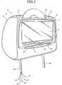
- FIG. 1is a front perspective view of an automobile entertainment system in accordance with the present invention.
- FIG. 2is a cross sectional view of the housing of the video system shown in FIG. 1 .
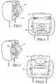
- FIGS. 3 and 4are front perspective views showing the entertainment system with the video system coupled to the headrest and detached from the headrest.
- FIGS. 5 , 6 , 7 and 8are views of entertainment systems in accordance with alternate embodiments of the present invention.
- FIG. 9shows the video system of FIG. 1 mounted within a dash docking station.
- FIG. 10shows the video system of FIG. 1 mounted within a mobile docking station.
- FIG. 11shows the video system of FIG. 1 mounted within a static docking station.
- FIG. 12is a side view of a vehicle seat incorporating an automobile entertainment system in accordance with an alternate embodiment of the present invention.
- FIG. 13is a detailed view of the automobile entertainment system shown in accordance with FIG. 12 .
- FIG. 14is a perspective view showing installation of the video system utilized in conjunction with the automobile entertainment system shown with reference to FIG. 12 .
- FIGS. 15 and 16are respectively a rear view and a side view of the video system of the automobile entertainment system shown with reference to FIG. 12 .
- FIG. 17is a perspective view showing the cradle of the automobile entertainment system with video system removed and a cover being selectively secured thereto.
- FIG. 18is a perspective view of the mounting bracket utilized in conjunction with the automobile entertainment system shown with reference to FIG. 12 .
- FIGS. 19 and 20are respectively a side view and a rear view showing an alternate embodiment of the automobile entertainment system shown with reference to FIGS. 12 to 18 .
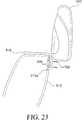
- FIG. 21is an exploded view of an automobile entertainment system in accordance with yet another embodiment.
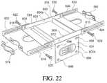
- FIG. 22is a perspective view of the mounting bracket utilized in conjunction with the automobile entertainment system shown with reference to FIG. 21 .
- FIG. 23is a side view showing mounting of the video system to the cradle of the embodiment shown with reference to FIG. 21 .
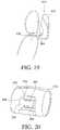
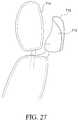
- FIG. 24is a perspective view in accordance with yet a further embodiment.
- FIGS. 25 and 26are respectively a rear view and a side view showing the video system and the video system mounted to the cradle (only shown in FIG. 26 ).
- FIG. 27is a side view of the video system shown with reference to FIG. 24 .
- an automobile entertainment system 10is disclosed.
- the automobile entertainment system 10is composed of a series of video and audio components integrated within an automobile 11 .
- the various embodiments of the present entertainment systemare disclosed herein with reference to their use within an automobile.
- the entertainment systemcould certainly be used in other vehicles, for example, boats or planes, without departing from the spirit of the present invention.
- the automobile entertainment system 10includes a video system 12 detachably mounted within a standard headrest 14 of an automobile 11 .
- the video system 12generally includes a video monitor 16 for presenting video content and a video source 20 integrated therewith.
- the video sourceis a DVD player 20 coupled to the video monitor 16 for the transmission of video content thereto. That is, the DVD player 20 or other video source is integrated within the same housing 18 as the video monitor 16 . It is also contemplated that a hard drive 23 video source may also be integrated with the video monitor 16 . As those skilled in the art will certainly appreciate, the hard drive 23 will include inputs for receiving video content and outputs for transmitting video content to the video monitor 16 , both of which are well known to those skilled in the art. However, and as discussed below in greater detail, the video source may take a variety of forms without departing from the spirit of the present invention; for example, and not limited to, satellite video systems and Bluetooth wireless based systems.
- the video system 12is mounted along the rear portion of the headrest 14 such that an individual sitting in the rear seat of the automobile 11 may watch the media presented on the video monitor 16 without disturbing the driver of the automobile 11 .
- the video monitor 16 , DVD player 20 and associated control componentsare mounted within the housing 18 .
- the video monitor 16is pivotally mounted within a recess 17 formed in the housing 18 .
- the video monitor 16is a TFT LCD screen.
- other monitor constructionsfor example, plasma, Ultra High Definition VGA, touch screen VGA, organic LED, fabric based monitors (e.g., flexible TFT) etc., may be used without departing from the spirit of the present invention.
- the present inventionis disclosed herein as including a single monitor, it is contemplated the system could be designed with dual monitors for viewing from opposite sides of the vehicle. Such a system could include distinct DVD players associated with each monitor or a single DVD player linked to both monitors.
- the DVD player 20With regard to the DVD player 20 , it is integrally molded within the housing 18 and positioned for insertion of DVDs behind the video monitor 16 . By mounting the DVD player 20 in this way, a stable structure is developed that is well adapted for the automobile environment.
- the DVD player 20is disclosed as being a slot-loaded design with insertion behind the video monitor, the DVD player could take a variety of other forms while still being integrated with the video monitor 16 .
- the DVD player 220may be positioned beneath the pivotally mounted video monitor 216 .
- the DVD player 320may be integrated with the video monitor 316 and facilitate access via a side loading slot 317 .
- the DVD player 420is integrated with the underside of the video monitor 416 and the DVD is snapped into DVD player 420 when the monitor 416 is pivoted upward.
- the DVD playermay be designed with a built-in TV tuner for providing the user with a choice of video sources.
- the housing 18is detachably secured to the headrest 14 .
- the housing 18including the video monitor 16 , DVD player 20 and other related components, is detachably mounted within a recess 15 formed in the headrest 14 .
- the video system 12may be removed from the automobile 11 and used at a variety of locations apart from the automobile 11 .
- the video system 12may be used alone or in conjunction with a docking station 50 ′, 50 ′′, 50 ′′′. Once removed, the video system 12 may be used in other automobiles 11 or within an individual's home.
- a battery packmay be connected to the video system 12 and the video system 12 can thereby become a portable entertainment system.
- a cradle 38 shaped and dimensioned for receiving the video system 12is provided within the recess 15 of the headrest 14 .
- similar cradles 38 ′, 38 ′′, 38 ′′′may be provided at other locations permitting use of the video system 12 at other remote locations. It is contemplated that such a cradle 38 , 38 ′, 38 ′′, 38 ′′′ would be much like the docking stations utilized with laptop computers wherein individuals are permitted to readily remove the laptop from a docking station for use at another location remote from the docking station.
- the cradle 38 utilized in the headrest 14includes quick release electrical connections 42 for the audio input 22 , audio output 24 , video input 26 , video output 28 and power supply 30 (although one embodiment contemplates a system which connects only to a power supply).
- the video system 12similarly includes mating electrical connections 44 for transmitting electricity and a/v signals between the cradle 38 and the video system 12 .
- the respective electrical connections 42 , 44mate to provide for the transmission of power and a/v signals between the video system 12 and the cradle 38 .
- other readily removable electrical connections for other purposesmay also be supplied if one determines they are so needed.
- the cradle 38also includes a connecting mechanism 46 designed for selectively retaining the video system 12 within the cradle 38 .
- the connecting mechanism 46permits ready and selective attachment of the video system 12 to the headrest 14 while preventing vibrations and other damaging movements that commonly occur in an automobile 11 .
- the connecting mechanism 46includes a release button 47 and a latch member 48 .
- the release button 47is actuated to rotate the latch member 48 and permit removal of the video system 12 from the cradle 38 . Insertion of the video system 12 within the headrest 14 is achieved by simply setting the video system 12 within the cradle 38 and applying sufficient force to the video system for overcoming the rotational force of the latch member 48 to force the video system 12 into a secure position. While a particular coupling structure is disclosed in accordance with a preferred embodiment of the present invention, those skilled in the art will appreciate that a variety of selectively releasable coupling structures may be employed without departing from the spirit of the present invention.
- the automobile entertainment system 10further includes cables 32 extending through the headrest 14 . These cables ultimately link audio, video and power to the cradle 38 and video system 12 . More specifically, the cradle 38 and video system 12 are electrically connected to the remainder of the automobile 11 via electrical communication lines extending through one or both of the extension arms 14 a , 14 b of the headrest 14 . For example, and as will be discussed below in substantial detail, a video input 22 , video output 24 , audio input 26 , audio output 28 and power source 30 , may be respectively connected to the cradle 38 for ultimate connection with the video system 12 via the mating electrical connections 42 , 44 of the respective cradle 38 and video system 12 .
- a DVD player 20is integrated with the video monitor 16 to form the video system 12 of the present invention.
- the DVD player 20is integrated with the video monitor 16 to facilitate convenient viewing of media on the video monitor 16 while also conserving space within the limited confines of the automobile 11 .
- individuals using the video monitor 16may conveniently insert DVDs within the video system 12 without reaching within another part of the automobile 11 .
- the present video system 12may be positioned within any headrest 14 employed in a car, truck, SUV, or van.
- the video system 12may be placed within all vehicle headrests (and, with regard to automobiles having three rows of seats, video systems may be positioned within both the front seat headrests and the second seat headrests). In this way, individuals sitting on opposite sides of an automobile 11 can watch different video content on different video systems 12 .
- different videosmay be viewed, and wireless headphones may still be employed, by utilizing a multi-channel IR transmitter in conjunction with the present system.
- the present video system 12is provided with the ability to offer a variety of functionalities. These functionalities may be hardwired or programmed within the video system 12 or the functionalities may be added in a modular manner via an expansion slot 40 provided within the video system 12 .
- Contemplated functionalitiesinclude, but are not limited to satellite radio (for example, SIRIUSXM), PICTEL phone, satellite television (for example, DIRECTV), GPS guidance systems, quick release battery packs, memory cards, wireless Internet access (for example, Wi-Fi), Bluetooth, digital video recorders, digital video reception and recording, digital video inputs, video conferencing, cellular digital, cellular digital with a camera, USB capabilities, BLUE SPHERE, hot swap hard drive, satellite video import card, wireless video import card, etc.
- RCA ports 34or other a/v input/outputs, formed within the cradle 38 and contained behind a cover 36 which may be selectively opened to reveal the ports 34 .
- the inclusion of these ports 34allows for ready attachment of the present video system 12 to other remote a/v sources (for example, game consoles, portable digital music players, etc.).
- a broadcast television receiver 19is integrated with the video monitor 16 and/or the headrest 14 . More particularly, and with reference to FIG. 2 , the housing 18 is provided with a rear recess 37 shaped and dimensioned for receiving a television receiver 19 .
- the television receiver 19may, therefore, be wired for use in conjunction with the video monitor 16 in a manner known to those skilled in the art.
- the television receiver 19is further provided with an antenna 21 .
- the antenna 21is electrically connected to the television receiver 19 for the transmission of over-the-air signals.
- the antenna 21is substantially U-shaped and is wrapped about the housing 18 . While a U-shaped antenna wrapped about the housing is disclosed in accordance with a preferred embodiment of the present invention, the antenna may be oriented within a variety of locations within the headrest without departing from the spirit of the present invention.
- control of the video system 12is facilitated by the provision of control buttons along the outer surface of the video system 12 .
- the control buttonstake the form of a multifunction controller 60 permitting movement of a cursor shown upon various interfaces displayed upon the video monitor 16 .
- conventional control buttons 62may also be provided for control of traditional functions.
- the video system 12may further include a remote control (not shown) such that an individual need not actually touch the video system 12 to control the video content or the volume generated by the video system 12 .
- the present video system 12is adapted for removal from the headrest 14 of an automobile 11 for use at a variety of other locations.
- the other locationsare provided with a docking station 50 ′, 50 ′′, 50 ′′′ including auxiliary cradles 38 ′, 38 ′′, 38 ′′′ shaped and dimensioned for receiving the video system 12 and coupling the video system 12 to power sources and a/v sources in a manner similar to the cradle 38 used in conjunction with the headrest 14 .
- a docking station 50 ′for use in conjunction with the dash 52 of a conventional automobile 11 is disclosed.
- the docking station 50 ′includes an auxiliary cradle 38 ′ (with electrical connections and a connecting mechanism (not shown)) shaped and dimensioned for receiving and securely holding the video system 12 and coupling the video system 12 to power sources and a/v sources in a manner similar to the cradle 38 used in conjunction with the headrest 14 .
- the docking station 50 ′is mounted upon the dash 52 of an automobile 11 and is wired for connection to a power source and a/v sources (not shown).
- the dash docking station 50 ′may include an integrated satellite receiver 54 ′ for providing satellite content to the passenger of the automobile 11 by transmitting the satellite signal through the cradle 38 ′ and into the video system 12 via the respective electrical connections of the cradle 38 ′ and the video system 12 .
- This embodimentis particularly useful where the video system 12 includes functionality relating to the provision of GPS guidance information.
- the driverwill be able to selectively use the video system 12 for accessing guidance information when needed and return the video system 12 to the headrest 14 when guidance information is no longer needed.
- a mobile docking station 50 ′′may also be provided.
- the mobile docking station 50 ′′also includes an auxiliary cradle 38 ′′ (with electrical connections and a connecting mechanism (not shown)) shaped and dimensioned for receiving and securely holding the video system 12 and coupling the video system 12 to power sources and a/v sources in a manner similar to the cradle 38 used in conjunction with the headrest 14 .
- the docking station 50 ′′may include a battery pack 55 ′′, a/v inputs 56 ′′, a/v outputs 57 ′′, internet capability, speakers 58 ′′, cable input 59 ′′ and/or an integrated satellite receiver 54 ′′. These components are linked to the video system 12 via the cradle 38 ′′ which transmits the relevant signals to and from the video system 12 via the respective electrical connections of the cradle 38 ′′ and the video system 12 .
- a docking station 50 ′′′is disclosed.
- This docking station 50 ′′′is adapted for static mounting within a household, office or other locations (for example, beneath a kitchen cabinet 53 ′′′).
- the docking station 50 ′′′includes an auxiliary cradle 38 ′′′ (with electrical connections and a connecting mechanism (not shown)) shaped and dimensioned for receiving and securely holding the video system 12 and coupling the video system to power sources and a/v sources in a manner similar to the cradle 38 used in conjunction with the headrest 14 .
- the docking station 50 ′′′may include a battery pack 55 ′′′, a/v inputs 56 ′′′, a/v outputs 57 ′′′, Internet capability, speakers 58 ′′′, cable input 59 ′′′ and/or an integrated satellite receiver 54 ′′′. These components are linked to the video system 12 via the cradle 38 ′′′ which transmits the relevant signals to and from the video system 12 via the respective electrical connections of the cradle 38 ′′′ and the video system 12 .
- the video system 12is provided with the ability to rotate to the image shown on the video monitor 16 so that the video system 12 may be used in a variety of orientations.
- the possible rotation of the image shown on the video monitor 16is complemented by the multifunctional controller 60 that adjusts to rotation of the image such that the controller 60 is calibrated to function in accordance with the orientation of the screen image.
- an automobile entertainment system 110providing for a selectively removable video system 112 mounted adjacent to the headrest of the automobile.
- an alternate video system 112 and mounting structureare disclosed.
- the video system 112is adapted for selective mounting within the seat back 113 of an automobile 111 adjacent to the headrest. This is achieved by providing a video system 112 having a limited profile and a low profile cradle 138 preferably mounted to the upper end 115 of the seat back 113 at a location adjacent to the headrest 114 .
- a conventional automobile seat 117includes a substantially horizontal sitting surface 119 and a seat back 113 extending upwardly therefrom.
- the seat back 113includes a lower end 127 positioned adjacent the horizontal sitting surface 119 and substantially horizontal (that is, when the seat back 113 is in its upright orientation) upper end 115 . Extending from the upper end 115 of the seat back 113 is a headrest 114 which is adjustably supported relative to the seat back 113 by one or more upwardly extending support posts 121 .
- the video system 112is detachably mounted within a cradle 138 secured to the seat back of an automobile 111 at a position adjacent to the headrest 114 .
- the video system 112generally includes a video monitor 116 for presenting media content and a video source 120 integrated therewith.
- the video sourceis a DVD player 120 coupled to the video monitor 116 for the transmission of video content thereto. That is, the DVD player 120 or other video source is integrated within the same video housing 118 as the video monitor 116 . It is also contemplated that a hard drive 123 video source may also be integrated with the video monitor 116 . As those skilled in the art will certainly appreciate, the hard drive 123 will include inputs for receiving video content and outputs for transmitting video content to the video monitor 116 , both of which are well known to those skilled in the art. However, and as discussed above with reference to the prior embodiments, the video source may take a variety of forms without departing from the spirit of the present invention.
- the video monitor 116 , DVD player 120 , hard drive 123 and associated control componentsare mounted within the video housing 118 .
- the video monitor 116is a TFT LCD screen.
- other monitor constructionsfor example, plasma, Ultra High Definition VGA, touch screen VGA, organic LED, fabric based monitors (e.g., flexible TFT) etc., may be used without departing from the spirit of the present invention.
- the DVD player 120it is integrally molded within the video housing 118 and positioned for insertion of the DVDs behind the video monitor 116 . By mounting the DVD player 120 in this way, a stable structure is developed that is well adapted for the automobile environment. While the DVD player is disclosed as being a slot-loaded design with insertion behind the video monitor, the DVD player could take a variety of other forms without departing from the spirit of the present invention.
- the video system 112is either detachably or fixedly mounted within a cradle 138 formed in the upper end 115 of the seat back of the automobile 111 .
- a cradle 138formed in the upper end 115 of the seat back of the automobile 111 .
- the design of the video system 112 and cradle 138allows for the creation of multiple cradles 138 within an automobile, permitting selective and convenient positioning and/or installation of the video systems 112 at the various cradle 138 locations within the automobile 111 .
- the base 164 of the video system 112is selectively mounted to a cradle 138 secured to the upper end 115 of the seat back 113 of the automobile 111 in a manner that permits rotation of the video housing 118 .
- the base 164extends from an edge of the video housing 118 .
- the base 164includes a first hinge 166 that facilitates rotation of the video housing 118 about an axis substantially parallel to the upper end 115 of the seat back 113 of the automobile 111 for movement to enhance viewing for passengers of different sizes.
- the first hinge 166also provides for rotation of the base 164 between an extended position in which the base 164 is oriented for attachment to the cradle 138 in a manner allowing for use of the present video system 112 and a storage position in which the base 164 is rotated about the first hinge 166 for positioning within a recess 168 within the back wall 125 of the video housing 118 .
- the recess 168is shaped and dimensioned to fully receive the base 164 such that the base 164 is substantially continuous with the outer surface of the video housing 118 when the base is in its storage position.
- the base 164projects from the video system 112 , permitting selective coupling of the video system 112 within the cradle secured to the upper end 115 of the seat back 113 of the automobile 111 .
- the base 164includes a fastening mechanism composed of latches 174 which fixedly secure the video system 112 to the cradle in a manner discussed below in greater detail.
- the latches 374are integrated with a spring biased actuation mechanism 380 which permits movement of latches 374 between an extended orientation and a retracted orientation.
- the actuation mechanism 380includes finger levers 382 , 384 which are pushed toward one another to retract the latches 374 .
- the latches 374may seat within recesses 376 found in the housing 318 of the video system 312 to prevent inadvertent movement of the base 364 .
- the finger levers 382 , 384are pressed releasing the latches 374 from within the recesses 376 and permitting rotation of the base 364 . Thereafter, the latches 374 may be used in securing the base 364 to the cradle 338 .
- the cradle 138is shaped and dimensioned for receiving and securing the video system 112 adjacent the headrest 114 at the upper end 115 of the seat back 113 of the automobile 111 . As was discussed above with reference to the other embodiments, similar cradles may be provided at other locations permitting use of the video system 112 at other remote locations.
- the cradle 138 utilized in accordance with a preferred embodiment of the present inventionincludes quick release electrical connections 142 for the audio input 122 , audio output 124 , video input 126 , video output 128 and power supply 130 (although one embodiment contemplates a system which connects only to a power supply).
- the video system 112and particularly, the base 164 of the video system 112 , includes mating electrical connections 144 for transmitting electricity and a/v signals between the cradle 138 and the video system 112 .
- the respective electrical connections 142 , 144mate to provide for the transmission of power and a/v signals between the video system 112 and the cradle 138 .
- other readily removable electrical connections for other purposesmay also be supplied if one determines they are so needed.
- the cradle 138also includes a fastening mechanism 190 adapted for selective engagement with the fastening mechanism 172 of video system 112 .
- the fastening mechanism 172 of the cradle 138is composed of latch members 176 shaped and dimensioned for receiving latches 174 in a manner discussed below in greater detail. Where a more permanent connector between the video system and cradle is desired, screws and screw holes in the cradle may be employed as shown with reference to the embodiment shown in FIGS. 21 and 23 .
- the cradle 138is formed with a low profile that substantially conforms to the shape of the upper end 115 of the seat back 113 of the automobile 111 . More particularly, each cradle 138 installed within an automobile 111 is positioned such that the faceplate 192 conforms with the upper end of the seat back. With this in mind, the cradle 138 is constructed with a metal mounting plate 196 directly secured to the upper end of the seat back of the automobile 111 and a docking port 198 secured thereto.
- the docking port 198includes the electrical and mechanical components discussed above which allow for the direct attachment of the video system 112 thereto.
- the mounting plate 196is shaped and dimensioned to extend laterally across the upper end 115 of the seat back 113 .
- the mounting plate 196includes first and second laterally clamp members 178 , 180 for engaging the support posts 121 of the headrest 114 and securing the mounting plate 196 thereto. In this way, the mounting plate 196 sits substantially between the upper end 115 of the seat back 113 and the lower portion 182 of the headrest 114 .
- the mounting plate 196also includes a central section 184 in which the docking port 186 is positioned.
- the mounting plate 196is desired for attachment to a variety of automobile seat structures. As such, the mounting plate 196 is formed with a three-piece construction allowing for adjustments to accommodate a variety of seat sizes.
- the mounting plate 196includes a central member 200 , a first lateral member 202 and a second lateral member 204 .
- the first and second lateral members 202 , 204are secured to opposite sides of the central member 200 for adjustment relative thereto.
- the central member 200includes upwardly extending walls 206 along the perimeter thereof which function to define a mounting area in which the base 164 of the video system 112 may be mounted.
- the central member 200includes a first lateral side 208 , a second lateral side 210 , a front side 212 and a rear side 214 .
- the first lateral member 202is secured to the central member 200 along the first lateral side 208 and the second lateral member 204 is secured to the central member 200 along the second lateral side 210 .
- the first lateral member 202is secured to the first lateral side 208 in a manner allowing one to selectively move the first lateral member relative to the central member 200 .
- first lateral member 202with forward and rearward tracks 216 , 218 in which set screws 220 , 222 extending to the central member 200 ride allowing for adjustment of the first lateral member 202 relative to the central member 200 .
- set screws 220 , 222are tightened securing the first lateral member 202 in position relative to the central member 200 .
- the second lateral member 204is secured to the second lateral side 210 in a manner allowing one to selectively move the second lateral member 204 relative to the central member 200 .
- the set screws 228 , 230are tightened securing the second lateral member 204 in position relative to the central member 200 .
- Adjustability of the first and second lateral members 202 , 204 , and ultimately the entire mounting plate 196is achieved by provided each of the first and second lateral members 202 , 204 with clamping members 178 , 180 at opposite ends of the adjustable mounting plate 196 .
- the clamping member 178 , 180allow for the passage of headrest support posts 121 , which are differently spaced, to pass through the mounting plate 196 regardless of the orientation of the first and second lateral members 202 , 204 relative the central member 200 .
- the installation of the cradle 138is intended to provided for an aesthetically pleasing appearance and the ceiling docking port 198 is, therefore, provided with a faceplate 192 which substantially aligns with and is, therefore, conforming with the upper end 115 of the seat back 113 of the automobile 111 .
- Aestheticsare further enhanced by the provision of a cover member 100 which may be selectively placed over the docking port 198 when it is not in use.
- the cover memberis preferably frictionally engaged with docking port 198 when positioned for covering. As shown with reference to FIG. 17 , the cover member may be a simple cover 100 .
- the covermay be a powered cover with various power sources extending therefrom or an illuminating cover with lights as disclosed in commonly owned U.S. patent application Ser. No. 11/177,405, filed Jul. 11, 2005, which is incorporated herein by reference. Where the covers require power, the cover is provided with an electrical connection allowing the cover to tap into the power supply of the cradle.
- cables 132extend through the seat back and the cradle 138 . These cables 132 ultimately link audio, video and power to the cradle 138 and video system 112 . More specifically, the cradle 138 and video system 112 are electrically connected to the remainder of the automobile 111 via electrical communication lines in a manner known to those skilled in the art.
- the video system 112is similarly provided with a base 164 including a fastening mechanism 172 adapted for secure attachment to the cradle.
- the mounting plate 196includes a rear facing structure shaped and dimensioned for engagement with the mounting plate and docking port of the cradle.
- the base 164 of the video system 112is pivotally secured to and extends from the video housing 118 in which the video monitor 116 and DVD player 120 are secured.
- the base 164may be secured to the cradle 138 such that the video housing 118 is positioned just rearwardly of the automobile headrest 114 for viewing from the rear seat thereof.
- the mounting plateis provided with screw holes through which screws are passed for engagement with threaded screw holes along the mounting plate of the cradle.
- the video systemis fixedly secured to the cradle for utilization in conjunction with the present invention.
- This fixed attachmentresults in a system which complies with all automobile regulations relating to the utilization of headrests and the attachment of devices within an automobile passenger compartment.
- the present video system 112is provided with the ability to offer a variety of functionalities. These functionalities may be hardwired or programmed within the video system 112 or the functionalities may be added in a modular manner via an expansion slot 140 provided within the video system 112 .
- Contemplated functionalitiesinclude, but are not limited to satellite radio (for example, SIRIUSXM), PICTEL phone, satellite television (for example, DIRECTV), GPS guidance systems, quick release battery packs, memory cards, wireless internet access (for example, Wi-Fi), Bluetooth, digital video recorders, digital video reception and recording, digital video inputs, video conferencing, cellular digital, cellular digital with a camera, USB capabilities, BLUE SPHERE, hot swap hard drive, satellite video import card, wireless video import card, etc.
- a broadcast television receiver and an antenna as discussed above with reference to the prior embodiment shown in FIG. 2is integrated with the video system 112 .
- the video systemmay also be provided with a flashlight 135 controlled by an on/off switch 135 a , which runs off a battery (not shown) mounted within the video system 112 .
- the video system 112may further be provided with both a 110 V power outlet 137 a and a 12 V power outlet 137 b for connection with other electronic devices requiring power.
- Control of the video system 112is facilitated by the provision of control buttons along the outer surface of the video system 112 .
- the control buttonstake the form of a multifunction controller 160 permitting movement of a cursor shown upon various interfaces displayed upon the video.
- conventional control buttons 162may also be provided for control of traditional functions.
- the video system 112may further include a remote control (not shown) such that an individual need not actually touch the video system 112 to control the video content or the volume generated by the video system 112 .
- the mounting plate 596 and faceplate 592are structured such that the docking port 598 faces rearwardly along the upper portion 513 a of the seat back 513 .
- the mounting plate 596is substantially L-shaped with a first leg 632 and a second leg 634 .
- the first leg 632is shaped and dimensioned for attachment to the upper end 515 of the seat back 513
- the second leg 634extends downwardly to wrap around the seat back 513 and extend along the upper portion 513 a along the rear portion of the seat back 513 adjacent the upper end 515 thereof.
- the first leg 632 of the mounting plate 596is shaped and dimensioned to extend laterally across the upper end 515 of the seat back 513 .
- the first leg 632 of the mounting plate 596includes first and second clamping members 578 , 580 for engaging the support posts 521 of the headrest assembly 514 .
- the mounting plate 596sits substantially between the upper end 515 of the seat back 513 and the lower portion 582 of the headrest 514 .
- the mounting plate 596also includes a central section 584 connecting the first and second clamping members 578 , 580 , and from which the second leg 634 extends and in which the docking port 598 is positioned.
- the mounting plate 596is desired for attachment to a variety of automobile seat structures.
- the mounting plate 596is formed with a three-piece construction allowing for adjustments to accommodate a variety of seat sizes.
- the mounting plate 596includes an L-shaped central member 600 , a first lateral member 602 and a second lateral member 604 .
- the first and second lateral members 602 , 604are secured to opposite sides of the central member 600 for adjustment relative thereto.
- the central member 600includes a horizontal plate member 600 a and a vertical plate 600 b.
- the horizontal plate member 600 a of the central member 600includes a first lateral side 608 , a second lateral side 610 , a front side 612 and a rear side 614 .
- the first lateral member 602is secured to the horizontal plate member 600 a of the central member 600 along the first lateral side 608 and the second lateral member 604 is secured to the horizontal plate member 600 a of the central member 600 along the second lateral side 610 .
- the first lateral member 602is secured to the first lateral side 608 in a manner allowing one to selectively move the first lateral member 602 relative to the horizontal plate member 600 a of the central member 600 .
- first lateral member 602with forward and rearward tracks 616 , 618 in which set screws 620 , 622 extending to the horizontal plate member 600 a of the central member 600 ride allowing for adjustment of the first lateral member 602 relative to the horizontal plate member 600 a of the central member 600 .
- set screws 620 , 622are tightened securing the first lateral member 602 in position relative to the horizontal plate member 600 a of the central member 600 .
- the second lateral member 604is secured to the second lateral side 610 in a manner allowing one to selectively move the second lateral member 604 relative to the horizontal plate member 600 a of the central member 600 .
- the second lateral member 604with forward and rearward tracks 624 , 626 in which set screws 628 , 630 extending to the horizontal plate member 600 a of the central member 600 ride allowing for adjustment of the second lateral member 604 relative to the horizontal plate member 600 a of the central member 600 .
- the set screws 628 , 630are tightened securing the second lateral member 604 in position relative to the horizontal plate member 600 a of the central member 600 .
- Adjustability of the first and second lateral members 602 , 604 , and ultimately the entire mounting plate 696is achieved by providing each of the first and second lateral members 602 , 604 with elongated openings 678 , 680 .
- the elongated openings 678 , 680allow for the passage of headrest support posts 621 , which are differently spaced, to pass through the mounting plate 696 regardless of the orientation of the first and second lateral members 602 , 604 relative the central member 600 .
- the base 664 of the video system 612would similarly be adjusted to allow for mounting and viewing from the back seat of the automobile.
- a fixed attachmentis disclosed, although it is contemplated a selectively releasable construction may be used. More particularly, the mounting plate 596 is provided with screw holes 698 through which screws 700 are passed for engagement with threaded screw holes 698 along the mounting plate 696 of the cradle 538 . In this way, the video system 512 is fixedly secured to the cradle 538 for utilization in conjunction with the present invention.
- This fixed attachmentresults in a system that complies with all automobile regulations relating to the utilization of headrests and the attachment of devices within an automobile passenger compartment.
- the cradle 738is oriented such that it is positioned rearward of the headrest 714 so that the video system 712 may be mounted thereto without the need of a pivoting base.
- the video system 712would be constructed with a base 764 statically fixed to the remainder of the housing 718 such that the base 764 , and associated video housing, may be directly secured to the cradle 738 without pivoting or other adjustments relating to the orientation of the video monitor.
- the video system 712 and cradle 738would be provided with electrical connections 742 , 744 and fastening mechanisms 772 , 790 as discussed above with regard to prior embodiments.
- the present video system 112is adapted for removal from the cradle 138 of an automobile 111 for use at a variety of other locations.
- the other locationsare provided with docking stations 150 ′, 150 ′′, 150 ′′′ including auxiliary cradles 138 ′, 138 ′′, 138 ′′′ shaped and dimensioned for receiving the video system 112 and coupling the video system 112 to power sources and a/v sources in a manner similar to the cradle 138 used in conjunction with the ceiling.
Landscapes
- Engineering & Computer Science (AREA)
- Mechanical Engineering (AREA)
- Chemical & Material Sciences (AREA)
- Combustion & Propulsion (AREA)
- Transportation (AREA)
- Multimedia (AREA)
- Signal Processing (AREA)
- Fittings On The Vehicle Exterior For Carrying Loads, And Devices For Holding Or Mounting Articles (AREA)
Abstract
Description
Claims (15)
Priority Applications (3)
| Application Number | Priority Date | Filing Date | Title |
|---|---|---|---|
| US12/103,428US8780282B2 (en) | 2003-11-07 | 2008-04-15 | Vehicle entertainment system |
| US14/330,532US9393915B2 (en) | 2003-11-07 | 2014-07-14 | Vehicle entertainment system |
| US15/214,058US9701257B2 (en) | 2003-11-07 | 2016-07-19 | Vehicle entertainment system |
Applications Claiming Priority (5)
| Application Number | Priority Date | Filing Date | Title |
|---|---|---|---|
| US51786203P | 2003-11-07 | 2003-11-07 | |
| US10/982,896US20050099547A1 (en) | 2003-11-07 | 2004-11-08 | Automobile entertainment system |
| US69087405P | 2005-06-16 | 2005-06-16 | |
| US11/177,405US7604273B2 (en) | 2003-11-07 | 2005-07-11 | Vehicle entertainment system |
| US12/103,428US8780282B2 (en) | 2003-11-07 | 2008-04-15 | Vehicle entertainment system |
Related Parent Applications (1)
| Application Number | Title | Priority Date | Filing Date |
|---|---|---|---|
| US11/177,405Continuation-In-PartUS7604273B2 (en) | 2003-11-07 | 2005-07-11 | Vehicle entertainment system |
Related Child Applications (1)
| Application Number | Title | Priority Date | Filing Date |
|---|---|---|---|
| US14/330,532ContinuationUS9393915B2 (en) | 2003-11-07 | 2014-07-14 | Vehicle entertainment system |
Publications (2)
| Publication Number | Publication Date |
|---|---|
| US20080252798A1 US20080252798A1 (en) | 2008-10-16 |
| US8780282B2true US8780282B2 (en) | 2014-07-15 |
Family
ID=39884566
Family Applications (3)
| Application Number | Title | Priority Date | Filing Date |
|---|---|---|---|
| US12/103,428Expired - Fee RelatedUS8780282B2 (en) | 2003-11-07 | 2008-04-15 | Vehicle entertainment system |
| US14/330,532Expired - Fee RelatedUS9393915B2 (en) | 2003-11-07 | 2014-07-14 | Vehicle entertainment system |
| US15/214,058Expired - Fee RelatedUS9701257B2 (en) | 2003-11-07 | 2016-07-19 | Vehicle entertainment system |
Family Applications After (2)
| Application Number | Title | Priority Date | Filing Date |
|---|---|---|---|
| US14/330,532Expired - Fee RelatedUS9393915B2 (en) | 2003-11-07 | 2014-07-14 | Vehicle entertainment system |
| US15/214,058Expired - Fee RelatedUS9701257B2 (en) | 2003-11-07 | 2016-07-19 | Vehicle entertainment system |
Country Status (1)
| Country | Link |
|---|---|
| US (3) | US8780282B2 (en) |
Cited By (5)
| Publication number | Priority date | Publication date | Assignee | Title |
|---|---|---|---|---|
| US20130264851A1 (en)* | 2012-04-05 | 2013-10-10 | Nhk Spring Co., Ltd. | Vehicle seat |
| US20140361995A1 (en)* | 2013-06-05 | 2014-12-11 | Hewlett-Packard Development Company, P.C | Computing device expansion system |
| US20160241069A1 (en)* | 2014-02-18 | 2016-08-18 | Mathew Inskeep | Dynamo Docking Station |
| US9446719B2 (en)* | 2014-11-19 | 2016-09-20 | Hon Hai Precision Industry Co., Ltd. | Holder for mobile device and vehicle seat employing same |
| US9919659B2 (en)* | 2015-12-22 | 2018-03-20 | Fca Us Llc | Adjustable mobile-device holder |
Families Citing this family (45)
| Publication number | Priority date | Publication date | Assignee | Title |
|---|---|---|---|---|
| US8780282B2 (en) | 2003-11-07 | 2014-07-15 | Voxx International Corporation | Vehicle entertainment system |
| JP2009500666A (en)* | 2005-07-07 | 2009-01-08 | トムソン ライセンシング | Flat screen display system with compatible stand |
| US8625034B2 (en)* | 2005-12-22 | 2014-01-07 | Johnson Controls Technology Company | Seatback entertainment display system |
| US20080170165A1 (en)* | 2007-01-16 | 2008-07-17 | Mark Lee | Reception Structure for Mobile Video and Audio Device |
| DK2276524T3 (en)* | 2008-05-07 | 2012-04-23 | Hoffmann La Roche | View in connection with an infusion management facility |
| US8203657B2 (en)* | 2008-07-11 | 2012-06-19 | Audiovox Corporation | Inductively powered mobile entertainment system |
| US20110155873A1 (en)* | 2009-12-30 | 2011-06-30 | Winegard Company | Mounting system for releasably securing an entertainment module to an automotive headrest |
| USD640654S1 (en) | 2009-12-30 | 2011-06-28 | Winegard Company | Portable entertainment module |
| DE102011083622A1 (en)* | 2011-09-28 | 2013-03-28 | Airbus Operations Gmbh | Seat with universal device for receiving an electronic device for an aircraft or spacecraft |
| DE102011083626B4 (en) | 2011-09-28 | 2023-05-25 | Airbus Operations Gmbh | Cover for a seat in an aircraft or spacecraft |
| US9120408B2 (en) | 2011-10-14 | 2015-09-01 | Jet Optoelectronics Co., Ltd. | Vehicle display system |
| US20130107449A1 (en)* | 2011-10-28 | 2013-05-02 | Yuan Zi Su | Tablet computer enclosure |
| DE102012210754A1 (en)* | 2012-06-25 | 2014-01-02 | Lufthansa Systems Ag | Seat for a vehicle as well as vehicle |
| DE102012014655A1 (en)* | 2012-07-24 | 2014-03-06 | Bomag Gmbh | Operating unit for a construction machine and method for operating the operating unit |
| US8601518B1 (en)* | 2012-11-13 | 2013-12-03 | Jet Optoelectronics Co., Ltd. | Vehicle display system |
| US8984566B2 (en) | 2013-01-07 | 2015-03-17 | Jet Optoelectronics Co., Ltd. | Video entertainment system |
| US9915976B2 (en) | 2013-03-15 | 2018-03-13 | Voxx International Corporation | Pivotable vehicle mounting system for mobile computing devices |
| US9170724B2 (en) | 2013-04-01 | 2015-10-27 | Jet Optoelectronics Co., Ltd. | Control and display system |
| ITTO20130470A1 (en)* | 2013-06-06 | 2014-12-07 | Fiat Group Automobiles Spa | VEHICLE DASHBOARD PROVIDED WITH A HOUSING TO SUPPORT A PORTABLE ELECTRONIC DEVICE |
| US9821713B2 (en) | 2013-10-07 | 2017-11-21 | Jet Optoelectronics Co., Ltd. | In-vehicle lighting device and operating method |
| USD880441S1 (en)* | 2013-11-01 | 2020-04-07 | Eugene M. Tuccinardi | Vehicle entertainment system for an active headrest |
| US9657891B1 (en)* | 2014-07-30 | 2017-05-23 | The Directv Group, Inc. | Bracket for mounting a user receiving device |
| US9421892B1 (en)* | 2015-01-29 | 2016-08-23 | Toyota Motor Engineering & Manufacturing North America, Inc. | Headrest with retainer |
| WO2016151022A1 (en)* | 2015-03-23 | 2016-09-29 | Johnson Controls Gmbh | Method for manufacturing a headrest comprising an integrated functional module |
| WO2017020070A1 (en) | 2015-07-31 | 2017-02-09 | Victor Harris | Vehicle seat accessory mounting system |
| US20170036616A1 (en)* | 2015-08-07 | 2017-02-09 | Jong Ho Lim | Monitor mount |
| US9937875B2 (en)* | 2016-08-25 | 2018-04-10 | Nsv Group Fzco | Vehicle entertainment center assembly with hanger |
| US10214154B2 (en)* | 2016-09-22 | 2019-02-26 | Lear Corporation | Vehicle seat including a support for a video device |
| US10099591B2 (en)* | 2016-12-01 | 2018-10-16 | David Flynn | Dual configuration headrest system |
| US10717378B2 (en)* | 2017-06-30 | 2020-07-21 | Faurecia Automotive Seating, Llc | Headrest for a vehicle seat |
| TWM566673U (en)* | 2018-03-22 | 2018-09-11 | 和碩聯合科技股份有限公司 | Installing bracket and electronic device assembly |
| US11483612B2 (en) | 2018-10-22 | 2022-10-25 | Voxx International Corporation | Vehicle entertainment system providing paired wireless connections for multiple wireless headphones and related methods |
| FR3089901B1 (en) | 2018-12-17 | 2020-12-18 | Faurecia Sieges Dautomobile | Vehicle seat headrest with audio speakers |
| USD918850S1 (en)* | 2019-02-15 | 2021-05-11 | Lg Electronics Inc. | Rear seat television monitor for automobiles |
| USD918852S1 (en)* | 2019-02-15 | 2021-05-11 | Lg Electronics Inc. | Rear seat television monitor for automobiles |
| USD919585S1 (en)* | 2019-02-15 | 2021-05-18 | Lg Electronics Inc. | Rear seat television monitor for automobiles |
| USD918851S1 (en)* | 2019-02-15 | 2021-05-11 | Lg Electronics Inc. | Rear seat television monitor for automobiles |
| USD918849S1 (en)* | 2019-02-15 | 2021-05-11 | Lg Electronics Inc. | Rear seat television monitor for automobiles |
| USD926148S1 (en)* | 2019-02-15 | 2021-07-27 | Lg Electronics Inc. | Rear seat television monitor for automobiles |
| US11014481B2 (en) | 2019-09-25 | 2021-05-25 | Faurecia Automotive Seating, Llc | Headrest for a vehicle seat |
| CN113443147A (en)* | 2020-03-24 | 2021-09-28 | 空中客车(中国)企业管理服务有限公司 | Integrated aircraft passenger entertainment device, aircraft passenger seat and aircraft |
| CN112124210A (en)* | 2020-08-28 | 2020-12-25 | 恒大新能源汽车投资控股集团有限公司 | Vehicle seat and motor vehicle |
| TWI785895B (en)* | 2021-11-18 | 2022-12-01 | 和碩聯合科技股份有限公司 | Installing module |
| US12151621B2 (en) | 2022-06-16 | 2024-11-26 | Honda Motor Co., Ltd. | Personal overhead display structure for vehicles |
| US12291099B2 (en) | 2022-10-25 | 2025-05-06 | Honda Motor Co., Ltd. | End zone overhead display structure for vehicles |
Citations (148)
| Publication number | Priority date | Publication date | Assignee | Title |
|---|---|---|---|---|
| US3019050A (en) | 1960-02-15 | 1962-01-30 | Aerotec Ind Inc | Aircraft seats and aircraft seating |
| US3512605A (en) | 1967-08-31 | 1970-05-19 | David D Mccorkle | Stereo speaker headrest for an automobile seat |
| US4490842A (en) | 1981-05-22 | 1984-12-25 | Clarion Co., Ltd. | Headrest speaker device |
| US4635110A (en) | 1985-09-13 | 1987-01-06 | Weinblatt Lee S | Portable video and audio equipment holder for use in an automobile |
| US4681366A (en) | 1984-07-02 | 1987-07-21 | Irvin Industries, Inc. | Vanity mirror or vehicle accessory assembly and mounting apparatus therefor |
| US4690362A (en) | 1984-06-26 | 1987-09-01 | Tangberg Data A/S | Adjustable stand for a visual display unit |
| US4792183A (en) | 1987-10-29 | 1988-12-20 | Townsend Iii William R | Desk for use in automobiles |
| US5161766A (en) | 1991-05-02 | 1992-11-10 | Arima Ronald H | Portable work station |
| US5396340A (en) | 1990-10-01 | 1995-03-07 | Sony Corporation | Optical disc reproducing apparatus having displaying made control key functions |
| US5436792A (en) | 1993-09-10 | 1995-07-25 | Compaq Computer Corporation | Pivotable docking station for use with notepad computer systems |
| US5507556A (en) | 1994-11-04 | 1996-04-16 | Burns Aerospace Corporation | Seat including an automatically adjustable display screen assembly |
| USD370214S (en) | 1994-10-18 | 1996-05-28 | Kabushiki Kaisha Toshiba | Electronic computer |
| US5544010A (en) | 1990-07-25 | 1996-08-06 | Norand Corporation | Portable electronic device docking system |
| US5611632A (en) | 1990-02-13 | 1997-03-18 | Canon Kabushiki Kaisha | Recording apparatus having biased recording means |
| US5661632A (en) | 1994-01-04 | 1997-08-26 | Dell Usa, L.P. | Hand held computer with dual display screen orientation capability controlled by toggle switches having first and second non-momentary positions |
| US5712949A (en) | 1991-01-29 | 1998-01-27 | Sony Corporation | Disc reproduction system with sequential reproduction of audio and image data |
| US5751548A (en) | 1996-05-13 | 1998-05-12 | International Business Machines Corporation | Docking station for a portable computer providing rotational movement of the computer's viewable screen in three different planes |
| US5842715A (en) | 1996-12-20 | 1998-12-01 | Jones; Christopher A. | Vehicular entertainment system |
| US5850215A (en) | 1995-03-20 | 1998-12-15 | Aisin Aw Co., Ltd. | Display apparatus for a car |
| US5910933A (en) | 1997-04-30 | 1999-06-08 | Gateway 2000, Inc | Stand alone optical disc player module |
| US5969939A (en) | 1997-07-08 | 1999-10-19 | Dell Usa, L.P. | Computer with docking station for docking and cooling the computer |
| US5982363A (en) | 1997-10-24 | 1999-11-09 | General Instrument Corporation | Personal computer-based set-top converter for television services |
| US5986634A (en) | 1996-12-11 | 1999-11-16 | Silicon Light Machines | Display/monitor with orientation dependent rotatable image |
| US5999880A (en) | 1996-11-19 | 1999-12-07 | Matsushita Electric Industrial Co., Ltd. | Relative car positioning system using car communication |
| US6007038A (en) | 1997-12-27 | 1999-12-28 | Daewoo Electronics Co., Ltd. | Tilt and swivel apparatus for a display monitor |
| US6012785A (en) | 1997-02-06 | 2000-01-11 | Nissan Motor Co., Ltd. | Retractable setting-up structure for car display |
| US6021185A (en) | 1993-09-28 | 2000-02-01 | Thomson Consumer Electronics S.A. | Method and apparatus for processing and displaying videotext or telephone data |
| US6023411A (en) | 1998-01-27 | 2000-02-08 | Dell U.S.A., L.P. | Modular docking tray and method |
| US6049450A (en) | 1997-10-13 | 2000-04-11 | Samsung Electronics Co., Ltd. | Portable computer on which a communication device can be mounted |
| US6059255A (en) | 1996-08-16 | 2000-05-09 | Rosen Products Llc | Stowable display apparatus |
| US6092705A (en) | 1998-08-03 | 2000-07-25 | Meritt; Ronald R. | Self-contained case for housing transporting and mounting video monitor and video player for use in passenger vehicles |
| US6105919A (en) | 1997-05-27 | 2000-08-22 | Samsung Electronics Co., Ltd. | Liquid crystal display with wide swivel angle |
| US6107933A (en) | 1996-12-05 | 2000-08-22 | Alpine Electronics, Inc. | Security system for vehicle navigation system and method of detecting identification code |
| US6116560A (en) | 1997-01-10 | 2000-09-12 | Samsung Electronics Co., Ltd. | Monitor stand with smooth tilting and rotating movements |
| US6124826A (en) | 1994-10-07 | 2000-09-26 | Mannesmann Aktiengesellschaft | Navigation device for people |
| US6130727A (en) | 1997-12-18 | 2000-10-10 | Harness System Technologies Research, Ltd. | On-vehicle unit |
| US6129321A (en) | 1998-11-16 | 2000-10-10 | Garmin Corporation | Mounting apparatus for an electronic device |
| US6186459B1 (en) | 1998-11-12 | 2001-02-13 | His-Kuang Ma | Angle/direction adjustable display device |
| US6199810B1 (en) | 1997-10-14 | 2001-03-13 | Sony Video Taiwan, Co., Ltd. | Flat-panel display assembly mountable in a vehicle |
| USD438853S1 (en) | 1999-12-27 | 2001-03-13 | Kabushiki Kaisha Toshiba | Digital videodisk player |
| US6208508B1 (en) | 1998-12-14 | 2001-03-27 | Compaq Computer Corporation | Space-saving docking station for vertically supporting an opened notebook computer |
| US6216927B1 (en) | 1998-08-03 | 2001-04-17 | Ronald Meritt | Mounting system for releasably and securely mounting an entertainment accessory within an automobile |
| FR2801854A1 (en) | 1999-12-07 | 2001-06-08 | Alain Henri Bernard Chemla | Bus/train/car TV monitor screen film/TV and game viewing has several TV monitors seat placed and DVD reader coupled |
| US6246449B1 (en) | 1996-08-16 | 2001-06-12 | Rosen Products Llc | Display unit |
| US6259601B1 (en) | 1999-09-30 | 2001-07-10 | Dell Usa, L.P. | Apparatus for providing docking station assisted cooling of a portable computer |
| US6263503B1 (en) | 1999-05-26 | 2001-07-17 | Neal Margulis | Method for effectively implementing a wireless television system |
| US6279977B1 (en) | 2000-05-23 | 2001-08-28 | Jack Chen | Armrest mounted computer dock |
| US6292236B1 (en) | 1999-03-26 | 2001-09-18 | Rosen Products Llc | Automotive-ceiling-mounted monitor |
| US6297795B1 (en) | 1997-02-24 | 2001-10-02 | International Business Machines Corporation | Small information processing apparatus |
| US20010048404A1 (en)* | 2000-05-23 | 2001-12-06 | Rosen Products Llc. | Ceiling mounted monitor system |
| US6339455B1 (en) | 1999-12-29 | 2002-01-15 | William L. Allan | Digital video disc vehicle television |
| US6380978B1 (en) | 1997-10-06 | 2002-04-30 | Dvdo, Inc. | Digital video system and methods for providing same |
| US20020068549A1 (en) | 1996-02-28 | 2002-06-06 | Robert Tendler | Location based service request system |
| US6409242B1 (en) | 2000-11-14 | 2002-06-25 | Chung L. Chang | Flat thin screen T/V monitor automotive roof mount |
| US6443574B1 (en) | 2001-07-24 | 2002-09-03 | Visteon Global Technologies, Inc. | Removable vehicle entertainment system |
| US20020128774A1 (en) | 2001-02-20 | 2002-09-12 | Matsushita Electric Industrial Co., Ltd. | Travel direction device and travel warning direction device |
| US20020135974A1 (en) | 2001-03-22 | 2002-09-26 | Bell Cynthia S. | Docking digital picture displays |
| US6464185B1 (en) | 1998-11-16 | 2002-10-15 | Garmin Corporation | Multi-position articulating mounting apparatus for an electronic device |
| US20020149708A1 (en) | 2000-07-28 | 2002-10-17 | Shigeru Nagata | Image reproducing device |
| US20020163219A1 (en) | 2001-05-01 | 2002-11-07 | Clark Kenneth M. | Modular system for a vehicle |
| US20020162319A1 (en) | 2001-05-03 | 2002-11-07 | Mark Crocker | Method for increasing internal combustion engine exhaust gas catalyst durability |
| US20020184632A1 (en) | 2001-05-30 | 2002-12-05 | Reitmeier Glenn A. | Computer peripheral device for web-enhanced media services |
| US20020186329A1 (en) | 2001-06-07 | 2002-12-12 | Ehometv [Hk] Ltd., | Electronic content modules and display dock |
| US6494527B1 (en) | 1999-07-14 | 2002-12-17 | Volkswagen Ag | Display and/or control unit for at least one electrical device in motor vehicles |
| US6516198B1 (en) | 1999-12-06 | 2003-02-04 | Tendler Cellular Inc | System for location reporting |
| FR2817812B1 (en) | 2000-12-12 | 2003-02-14 | Faurecia Sieges Automobile | MOTOR VEHICLE SEAT WITH VIDEO DISPLAY SCREEN |
| US6522368B1 (en) | 2000-05-19 | 2003-02-18 | Timely Innovations, Lp | Portable vehicle video system |
| US6530547B1 (en) | 1999-02-26 | 2003-03-11 | Sony Corporation | Display apparatus |
| US6556435B1 (en) | 1997-10-31 | 2003-04-29 | Hewlett-Packard Company | Adjustable height docking station and computing device for use therewith |
| US6578935B1 (en) | 2002-03-22 | 2003-06-17 | Scosche Industries, Inc. | Slider tray storage apparatus |
| US20030125873A1 (en) | 2001-12-28 | 2003-07-03 | Pioneer Corporation | Display controller, display control method, drive controller and drive control method |
| US20030128505A1 (en) | 2002-01-07 | 2003-07-10 | Yin Memphis Zhihong | Portable computer docking station with movable electrical interface |
| US6597384B1 (en) | 1999-12-22 | 2003-07-22 | Intel Corporation | Automatic reorienting of screen orientation using touch sensitive system |
| US20030137584A1 (en) | 2001-10-29 | 2003-07-24 | Gene Norvell | Detachable vehicle monitor |
| US6606543B1 (en) | 2002-01-09 | 2003-08-12 | Microsoft Corporation | Method and apparatus for logging into a vehicle computer system |
| US6608399B2 (en) | 2000-10-17 | 2003-08-19 | Lear Corporation | Vehicle universal docking station and electronic feature modules |
| US6619605B2 (en) | 2000-01-15 | 2003-09-16 | Graham Keith Lambert | Mounting assembly for in-car video ststems |
| US20030184137A1 (en) | 2001-09-26 | 2003-10-02 | Gilbert Jost | Method for assembling a case on a cushion, protection cover fitted with case and cushion fitted with such cover |
| US6633347B2 (en) | 2001-01-02 | 2003-10-14 | Alpine Electronics, Inc. | Display assembly having display supported on casing to be controllable in attitude |
| US20030192950A1 (en) | 2002-04-12 | 2003-10-16 | Muterspaugh Matthew Ward | PDA television module |
| US6644616B1 (en) | 1999-12-14 | 2003-11-11 | Fujitsu Limited | Tilt swivel stand |
| US20030226148A1 (en) | 2002-05-30 | 2003-12-04 | Ferguson Andrew H. | Removable vehicular audio-video systems |
| US6663155B1 (en) | 1999-10-27 | 2003-12-16 | Meridian Automotive Sytems, Inc. | Vehicular console with adjustably-mounted video display unit |
| US6663064B1 (en) | 1999-12-01 | 2003-12-16 | Garmin Corporation | Multi-position articulating mounting apparatus for an electronic device |
| US6678892B1 (en) | 2000-10-27 | 2004-01-13 | Audivox Corporation | Multimedia entertainment unit for use in a vehicle |
| US20040017652A1 (en) | 2001-10-25 | 2004-01-29 | Hewlett-Packard Company | Pedestal computer docking station |
| US6685016B2 (en) | 2001-12-01 | 2004-02-03 | Cfs Products L.L.C. | Entertainment system comprising suspension platform |
| US6690268B2 (en) | 2000-03-02 | 2004-02-10 | Donnelly Corporation | Video mirror systems incorporating an accessory module |
| US20040032541A1 (en)* | 2002-08-13 | 2004-02-19 | Sohail Rochel | Universal vehicle headrest monitor supporting bracket assembly |
| US6698832B2 (en) | 2001-05-25 | 2004-03-02 | Johnson Controls Technology Company | Video screen integrated in a head rest |
| US6702238B1 (en) | 2003-03-28 | 2004-03-09 | Top Victory Electronics Co., Ltd. | Adjustable supporting device for a display panel |
| US6714253B2 (en) | 2000-03-06 | 2004-03-30 | Lg Electronics Inc. | Method of displaying digital broadcasting signals through a digital broadcasting receiver and a display device |
| US20040061995A1 (en) | 2002-09-28 | 2004-04-01 | Mcmahon Edward L. | Portable computer docking station for vehicles |
| US6724317B1 (en) | 2000-03-29 | 2004-04-20 | Mitsubishi Denki Kabushiki Kaisha | Audiovisual player system |
| US20040086259A1 (en) | 2002-11-04 | 2004-05-06 | Audiovox Corporation | Hood for vehicle seat headrest including a video system |
| US20040085485A1 (en) | 2002-11-05 | 2004-05-06 | Audiovox Corporation | Mobile video system |
| US20040104905A1 (en) | 2002-12-02 | 2004-06-03 | Tatung Co., Ltd. | Apparatus capable of controlling brightness switching between a protable device and a docking station |
| US6746065B1 (en) | 2002-06-13 | 2004-06-08 | Vis Racing Sports, Inc. | Armrest mounted video display screen |
| US20040130616A1 (en) | 2003-01-03 | 2004-07-08 | Thomas Tseng | Flip-open screen with audio/video player |
| US6768896B2 (en) | 2000-09-25 | 2004-07-27 | Possio Ab | Wireless systems internet gateway |
| US6769989B2 (en) | 1998-09-08 | 2004-08-03 | Nintendo Of America Inc. | Home video game system with hard disk drive and internet access capability |
| US6779196B1 (en) | 1998-06-22 | 2004-08-17 | Phillip Igbinadolor | Integrated car dubbing system |
| US20040175155A1 (en) | 2003-03-03 | 2004-09-09 | Edward Liu | Portable DVD player and console arrangement |
| US6791471B2 (en) | 2002-10-01 | 2004-09-14 | Electric Data Systems | Communicating position information between vehicles |
| US20040204130A1 (en) | 2002-08-30 | 2004-10-14 | Khazaka Samir Khalil | Display format for handheld wireless communication devices |
| US20040212957A1 (en) | 2003-04-25 | 2004-10-28 | Audiovox Corporation | Portable video system |
| US20040224638A1 (en) | 2003-04-25 | 2004-11-11 | Apple Computer, Inc. | Media player system |
| US20040227861A1 (en) | 2003-05-15 | 2004-11-18 | Schedivy George C. | Video display system |
| US20040228622A1 (en) | 2003-05-15 | 2004-11-18 | Audiovox Corporation | Portable video system |
| US20040227695A1 (en) | 2003-05-15 | 2004-11-18 | Schedivy George C. | Headrest mountable video system |
| US20040227731A1 (en) | 2002-12-16 | 2004-11-18 | Gould Bear Eric Justin | Systems and methods for interfacing with computer devices |
| US20040227696A1 (en) | 2003-05-15 | 2004-11-18 | Audiovox Corporation | Headrest mountable video system |
| US20050025466A1 (en) | 2003-03-12 | 2005-02-03 | Meng-Shin Yen | Audio video playing/displaying apparatus with detachable media-accessing device |
| US6865075B2 (en) | 2002-06-27 | 2005-03-08 | Intel Corporation | Transformable computing apparatus |
| US6871356B2 (en) | 2002-10-28 | 2005-03-22 | Johnson Safety, Inc. | Mobile video system |
| US20050075783A1 (en) | 2003-07-24 | 2005-04-07 | Stefan Wolf | System for providing data in a mobile device |
| US20050090288A1 (en) | 2003-10-22 | 2005-04-28 | Josef Stohr | Mobile communication terminal with multi orientation user interface |
| US6889365B2 (en) | 1998-08-10 | 2005-05-03 | Fujitsu Limited | Terminal operation apparatus |
| US6899365B2 (en) | 2003-05-15 | 2005-05-31 | Audiovox Corporation | Seat mountable entertainment system |
| US6941239B2 (en)* | 1996-07-03 | 2005-09-06 | Hitachi, Ltd. | Method, apparatus and system for recognizing actions |
| US20050200697A1 (en) | 2003-05-15 | 2005-09-15 | Audiovox Corporation | Headrest mountable video system |
| US20050278091A1 (en) | 2004-06-10 | 2005-12-15 | Visteon Global Technologies, Inc. | Dual image display |
| US6979038B1 (en) | 2003-09-15 | 2005-12-27 | Ktv Usa, Inc. | Video monitor hinge assembly |
| US20060061145A1 (en) | 2002-11-07 | 2006-03-23 | Johnson Controls Technology Company | Structual roof panel systems |
| US7040698B2 (en) | 2002-07-02 | 2006-05-09 | Savv Corporation | Headrest mounted video display |
| US20060107295A1 (en) | 2004-06-15 | 2006-05-18 | Panasonic Avionics Corporation | Portable media device and method for presenting viewing content during travel |
| US20060109388A1 (en) | 1998-12-28 | 2006-05-25 | Johnson Controls Technology Company | Wireless signal system for a video display unit |
| US20060128303A1 (en) | 2004-12-15 | 2006-06-15 | Audiovox Corporation | Entertainment system for use in a vehicle |
| US7066544B2 (en) | 2004-09-23 | 2006-06-27 | Baton Digital Electronic Tech. Co., Ltd. | Headrest mounting structure |
| US7084932B1 (en) | 1999-12-28 | 2006-08-01 | Johnson Controls Technology Company | Video display system for a vehicle |
| US7111814B1 (en) | 2003-09-17 | 2006-09-26 | David Newman | Mounting arm |
| US7117286B2 (en) | 2002-11-15 | 2006-10-03 | Microsoft Corporation | Portable computing device-integrated appliance |
| US7124989B1 (en) | 2003-09-17 | 2006-10-24 | Ktv Usa, Inc. | Latch system for video monitor |
| US20070052618A1 (en) | 2003-05-15 | 2007-03-08 | Samsung Electronics Co., Ltd. | Entertainment system mountable in a vehicle seat |
| US7201443B2 (en) | 2004-10-22 | 2007-04-10 | Alpine Electronics, Inc. | Method and apparatus for mounting rear seat entertainment device |
| US7236213B2 (en) | 2002-10-24 | 2007-06-26 | Pioneer Corporation | Receiving apparatus and receiving method of reduced power consumption for receiving a broadcast transmission |
| US7239040B2 (en) | 2003-07-25 | 2007-07-03 | Alpine Electronics, Inc. | Method and apparatus for releasing brake interlock function for vehicle audio/video display unit |
| US20070153140A1 (en) | 2002-08-08 | 2007-07-05 | Pioneer Corporation | Broadcast receiver |
| US7267402B2 (en) | 2002-08-14 | 2007-09-11 | Johnson Safety, Inc. | Headrest-mounted monitor |
| US7295921B2 (en) | 1999-10-19 | 2007-11-13 | Magellan Navigation, Inc. | Portable vehicle navigation system |
| US20080067305A1 (en) | 2005-03-18 | 2008-03-20 | Rob Mossman | Video monitor mount |
| US7448679B2 (en) | 2002-08-14 | 2008-11-11 | Chang Chung L | Headrest-mounted monitor |
| US20090089841A1 (en)* | 2007-10-01 | 2009-04-02 | Lear Corporation | Seat-mounted electronics assembly |
| US20090316057A1 (en)* | 2005-12-22 | 2009-12-24 | Johnson Controls Technology Company | Seatback Entertainment Display System |
| US7637565B2 (en)* | 2006-03-16 | 2009-12-29 | Toyota Boshoku Kabushiki Kaisha | Vehicle seat with monitor |
| US7758116B2 (en)* | 2007-02-23 | 2010-07-20 | Toyota Boshoku Kabushiki Kaisha | Monitor unit for a vehicle seat |
| US7812784B2 (en)* | 2005-11-02 | 2010-10-12 | Chung Lung Chang | Headrest mounted entertainment system |
| JP5050883B2 (en) | 2008-01-31 | 2012-10-17 | タイガー魔法瓶株式会社 | Electric kettle |
Family Cites Families (12)
| Publication number | Priority date | Publication date | Assignee | Title |
|---|---|---|---|---|
| US763565A (en)* | 1903-01-10 | 1904-06-28 | Jacob Wilfrid Madigin | Secondary battery. |
| US5312605A (en)* | 1991-12-11 | 1994-05-17 | Northeastern University | Method for simultaneously removing SO2 and NOX pollutants from exhaust of a combustion system |
| US6729977B1 (en)* | 2003-02-07 | 2004-05-04 | Fairway Products International, Llc. | Golf tee with tactile height adjustment |
| US8780282B2 (en) | 2003-11-07 | 2014-07-15 | Voxx International Corporation | Vehicle entertainment system |
| US20050099547A1 (en)* | 2003-11-07 | 2005-05-12 | Vitito Christopher J. | Automobile entertainment system |
| USD521964S1 (en) | 2004-07-30 | 2006-05-30 | Coby Electronics Corporation | Portable DVD player with stand |
| GB0609240D0 (en)* | 2006-05-10 | 2006-06-21 | Mitchell Ciaran | Seat top console for vehicle entertainment and accessories |
| US8730413B2 (en)* | 2007-01-05 | 2014-05-20 | Voxx International Corporation | Rear seat entertainment system for a vehicle having an active headrest |
| JP5233283B2 (en)* | 2008-01-08 | 2013-07-10 | トヨタ紡織株式会社 | Vehicle seat with monitor |
| US20100244505A1 (en)* | 2009-03-31 | 2010-09-30 | Gm Global Technology Operations, Inc. | Video Screen Assembly For Vehicle |
| US20120125959A1 (en)* | 2009-11-03 | 2012-05-24 | Kucera Curtis C | Monitor-mounting system for a land vehicle headrest |
| US20110155873A1 (en)* | 2009-12-30 | 2011-06-30 | Winegard Company | Mounting system for releasably securing an entertainment module to an automotive headrest |
- 2008
- 2008-04-15USUS12/103,428patent/US8780282B2/ennot_activeExpired - Fee Related
- 2014
- 2014-07-14USUS14/330,532patent/US9393915B2/ennot_activeExpired - Fee Related
- 2016
- 2016-07-19USUS15/214,058patent/US9701257B2/ennot_activeExpired - Fee Related
Patent Citations (162)
| Publication number | Priority date | Publication date | Assignee | Title |
|---|---|---|---|---|
| US3019050A (en) | 1960-02-15 | 1962-01-30 | Aerotec Ind Inc | Aircraft seats and aircraft seating |
| US3512605A (en) | 1967-08-31 | 1970-05-19 | David D Mccorkle | Stereo speaker headrest for an automobile seat |
| US4490842A (en) | 1981-05-22 | 1984-12-25 | Clarion Co., Ltd. | Headrest speaker device |
| US4690362A (en) | 1984-06-26 | 1987-09-01 | Tangberg Data A/S | Adjustable stand for a visual display unit |
| US4681366A (en) | 1984-07-02 | 1987-07-21 | Irvin Industries, Inc. | Vanity mirror or vehicle accessory assembly and mounting apparatus therefor |
| US4635110A (en) | 1985-09-13 | 1987-01-06 | Weinblatt Lee S | Portable video and audio equipment holder for use in an automobile |
| US4792183A (en) | 1987-10-29 | 1988-12-20 | Townsend Iii William R | Desk for use in automobiles |
| US5611632A (en) | 1990-02-13 | 1997-03-18 | Canon Kabushiki Kaisha | Recording apparatus having biased recording means |
| US5544010A (en) | 1990-07-25 | 1996-08-06 | Norand Corporation | Portable electronic device docking system |
| US5396340A (en) | 1990-10-01 | 1995-03-07 | Sony Corporation | Optical disc reproducing apparatus having displaying made control key functions |
| US5712949A (en) | 1991-01-29 | 1998-01-27 | Sony Corporation | Disc reproduction system with sequential reproduction of audio and image data |
| US5161766A (en) | 1991-05-02 | 1992-11-10 | Arima Ronald H | Portable work station |
| US5436792A (en) | 1993-09-10 | 1995-07-25 | Compaq Computer Corporation | Pivotable docking station for use with notepad computer systems |
| US6021185A (en) | 1993-09-28 | 2000-02-01 | Thomson Consumer Electronics S.A. | Method and apparatus for processing and displaying videotext or telephone data |
| US5661632A (en) | 1994-01-04 | 1997-08-26 | Dell Usa, L.P. | Hand held computer with dual display screen orientation capability controlled by toggle switches having first and second non-momentary positions |
| US6124826A (en) | 1994-10-07 | 2000-09-26 | Mannesmann Aktiengesellschaft | Navigation device for people |
| USD370214S (en) | 1994-10-18 | 1996-05-28 | Kabushiki Kaisha Toshiba | Electronic computer |
| US5507556A (en) | 1994-11-04 | 1996-04-16 | Burns Aerospace Corporation | Seat including an automatically adjustable display screen assembly |
| US5850215A (en) | 1995-03-20 | 1998-12-15 | Aisin Aw Co., Ltd. | Display apparatus for a car |
| US20020068549A1 (en) | 1996-02-28 | 2002-06-06 | Robert Tendler | Location based service request system |
| US5751548A (en) | 1996-05-13 | 1998-05-12 | International Business Machines Corporation | Docking station for a portable computer providing rotational movement of the computer's viewable screen in three different planes |
| US6941239B2 (en)* | 1996-07-03 | 2005-09-06 | Hitachi, Ltd. | Method, apparatus and system for recognizing actions |
| US6246449B1 (en) | 1996-08-16 | 2001-06-12 | Rosen Products Llc | Display unit |
| US6059255A (en) | 1996-08-16 | 2000-05-09 | Rosen Products Llc | Stowable display apparatus |
| US5999880A (en) | 1996-11-19 | 1999-12-07 | Matsushita Electric Industrial Co., Ltd. | Relative car positioning system using car communication |
| US6107933A (en) | 1996-12-05 | 2000-08-22 | Alpine Electronics, Inc. | Security system for vehicle navigation system and method of detecting identification code |
| US5986634A (en) | 1996-12-11 | 1999-11-16 | Silicon Light Machines | Display/monitor with orientation dependent rotatable image |
| US5842715A (en) | 1996-12-20 | 1998-12-01 | Jones; Christopher A. | Vehicular entertainment system |
| US6116560A (en) | 1997-01-10 | 2000-09-12 | Samsung Electronics Co., Ltd. | Monitor stand with smooth tilting and rotating movements |
| US6012785A (en) | 1997-02-06 | 2000-01-11 | Nissan Motor Co., Ltd. | Retractable setting-up structure for car display |
| US6297795B1 (en) | 1997-02-24 | 2001-10-02 | International Business Machines Corporation | Small information processing apparatus |
| US5910933A (en) | 1997-04-30 | 1999-06-08 | Gateway 2000, Inc | Stand alone optical disc player module |
| US6105919A (en) | 1997-05-27 | 2000-08-22 | Samsung Electronics Co., Ltd. | Liquid crystal display with wide swivel angle |
| US20020005917A1 (en) | 1997-06-27 | 2002-01-17 | Rosen John B. | Display unit |
| US5969939A (en) | 1997-07-08 | 1999-10-19 | Dell Usa, L.P. | Computer with docking station for docking and cooling the computer |
| US6380978B1 (en) | 1997-10-06 | 2002-04-30 | Dvdo, Inc. | Digital video system and methods for providing same |
| US6049450A (en) | 1997-10-13 | 2000-04-11 | Samsung Electronics Co., Ltd. | Portable computer on which a communication device can be mounted |
| US6199810B1 (en) | 1997-10-14 | 2001-03-13 | Sony Video Taiwan, Co., Ltd. | Flat-panel display assembly mountable in a vehicle |
| US5982363A (en) | 1997-10-24 | 1999-11-09 | General Instrument Corporation | Personal computer-based set-top converter for television services |
| US6556435B1 (en) | 1997-10-31 | 2003-04-29 | Hewlett-Packard Company | Adjustable height docking station and computing device for use therewith |
| US6130727A (en) | 1997-12-18 | 2000-10-10 | Harness System Technologies Research, Ltd. | On-vehicle unit |
| US6007038A (en) | 1997-12-27 | 1999-12-28 | Daewoo Electronics Co., Ltd. | Tilt and swivel apparatus for a display monitor |
| US6023411A (en) | 1998-01-27 | 2000-02-08 | Dell U.S.A., L.P. | Modular docking tray and method |
| US6779196B1 (en) | 1998-06-22 | 2004-08-17 | Phillip Igbinadolor | Integrated car dubbing system |
| US6216927B1 (en) | 1998-08-03 | 2001-04-17 | Ronald Meritt | Mounting system for releasably and securely mounting an entertainment accessory within an automobile |
| US20010011664A1 (en) | 1998-08-03 | 2001-08-09 | Nissho Iwai American Corporation | Mounting system for releasably and securely mounting an entertainment accessory within an automobile |
| US6092705A (en) | 1998-08-03 | 2000-07-25 | Meritt; Ronald R. | Self-contained case for housing transporting and mounting video monitor and video player for use in passenger vehicles |
| US6889365B2 (en) | 1998-08-10 | 2005-05-03 | Fujitsu Limited | Terminal operation apparatus |
| US6769989B2 (en) | 1998-09-08 | 2004-08-03 | Nintendo Of America Inc. | Home video game system with hard disk drive and internet access capability |
| US6186459B1 (en) | 1998-11-12 | 2001-02-13 | His-Kuang Ma | Angle/direction adjustable display device |
| US6129321A (en) | 1998-11-16 | 2000-10-10 | Garmin Corporation | Mounting apparatus for an electronic device |
| US6464185B1 (en) | 1998-11-16 | 2002-10-15 | Garmin Corporation | Multi-position articulating mounting apparatus for an electronic device |
| US6208508B1 (en) | 1998-12-14 | 2001-03-27 | Compaq Computer Corporation | Space-saving docking station for vertically supporting an opened notebook computer |
| US20060109388A1 (en) | 1998-12-28 | 2006-05-25 | Johnson Controls Technology Company | Wireless signal system for a video display unit |
| US6530547B1 (en) | 1999-02-26 | 2003-03-11 | Sony Corporation | Display apparatus |
| US6292236B1 (en) | 1999-03-26 | 2001-09-18 | Rosen Products Llc | Automotive-ceiling-mounted monitor |
| US6263503B1 (en) | 1999-05-26 | 2001-07-17 | Neal Margulis | Method for effectively implementing a wireless television system |
| US6494527B1 (en) | 1999-07-14 | 2002-12-17 | Volkswagen Ag | Display and/or control unit for at least one electrical device in motor vehicles |
| US6259601B1 (en) | 1999-09-30 | 2001-07-10 | Dell Usa, L.P. | Apparatus for providing docking station assisted cooling of a portable computer |
| US7295921B2 (en) | 1999-10-19 | 2007-11-13 | Magellan Navigation, Inc. | Portable vehicle navigation system |
| US6663155B1 (en) | 1999-10-27 | 2003-12-16 | Meridian Automotive Sytems, Inc. | Vehicular console with adjustably-mounted video display unit |
| US6663064B1 (en) | 1999-12-01 | 2003-12-16 | Garmin Corporation | Multi-position articulating mounting apparatus for an electronic device |
| US6516198B1 (en) | 1999-12-06 | 2003-02-04 | Tendler Cellular Inc | System for location reporting |
| FR2801854A1 (en) | 1999-12-07 | 2001-06-08 | Alain Henri Bernard Chemla | Bus/train/car TV monitor screen film/TV and game viewing has several TV monitors seat placed and DVD reader coupled |
| US6644616B1 (en) | 1999-12-14 | 2003-11-11 | Fujitsu Limited | Tilt swivel stand |
| US6597384B1 (en) | 1999-12-22 | 2003-07-22 | Intel Corporation | Automatic reorienting of screen orientation using touch sensitive system |
| USD438853S1 (en) | 1999-12-27 | 2001-03-13 | Kabushiki Kaisha Toshiba | Digital videodisk player |
| US7084932B1 (en) | 1999-12-28 | 2006-08-01 | Johnson Controls Technology Company | Video display system for a vehicle |
| US6339455B1 (en) | 1999-12-29 | 2002-01-15 | William L. Allan | Digital video disc vehicle television |
| US6619605B2 (en) | 2000-01-15 | 2003-09-16 | Graham Keith Lambert | Mounting assembly for in-car video ststems |
| US6690268B2 (en) | 2000-03-02 | 2004-02-10 | Donnelly Corporation | Video mirror systems incorporating an accessory module |
| US6714253B2 (en) | 2000-03-06 | 2004-03-30 | Lg Electronics Inc. | Method of displaying digital broadcasting signals through a digital broadcasting receiver and a display device |
| US6724317B1 (en) | 2000-03-29 | 2004-04-20 | Mitsubishi Denki Kabushiki Kaisha | Audiovisual player system |
| US6522368B1 (en) | 2000-05-19 | 2003-02-18 | Timely Innovations, Lp | Portable vehicle video system |
| US6279977B1 (en) | 2000-05-23 | 2001-08-28 | Jack Chen | Armrest mounted computer dock |
| US20010048404A1 (en)* | 2000-05-23 | 2001-12-06 | Rosen Products Llc. | Ceiling mounted monitor system |
| US20040189881A1 (en) | 2000-05-23 | 2004-09-30 | Cook Mark A. | Ceiling mounted monitor system |
| US7280166B2 (en) | 2000-07-28 | 2007-10-09 | Mitsubishi Denki Kabushiki Kaisha | Image reproducing device |
| US20020149708A1 (en) | 2000-07-28 | 2002-10-17 | Shigeru Nagata | Image reproducing device |
| US6768896B2 (en) | 2000-09-25 | 2004-07-27 | Possio Ab | Wireless systems internet gateway |
| US6608399B2 (en) | 2000-10-17 | 2003-08-19 | Lear Corporation | Vehicle universal docking station and electronic feature modules |
| US6678892B1 (en) | 2000-10-27 | 2004-01-13 | Audivox Corporation | Multimedia entertainment unit for use in a vehicle |
| US6409242B1 (en) | 2000-11-14 | 2002-06-25 | Chung L. Chang | Flat thin screen T/V monitor automotive roof mount |
| US20050046756A1 (en) | 2000-11-14 | 2005-03-03 | Chang Chung L. | Flat thin screen TV/monitor automotive roof mount |
| FR2817812B1 (en) | 2000-12-12 | 2003-02-14 | Faurecia Sieges Automobile | MOTOR VEHICLE SEAT WITH VIDEO DISPLAY SCREEN |
| US6633347B2 (en) | 2001-01-02 | 2003-10-14 | Alpine Electronics, Inc. | Display assembly having display supported on casing to be controllable in attitude |
| US20020128774A1 (en) | 2001-02-20 | 2002-09-12 | Matsushita Electric Industrial Co., Ltd. | Travel direction device and travel warning direction device |
| US6717798B2 (en) | 2001-03-22 | 2004-04-06 | Intel Corporation | Docking digital picture displays |
| US20020135974A1 (en) | 2001-03-22 | 2002-09-26 | Bell Cynthia S. | Docking digital picture displays |
| US6669260B2 (en) | 2001-05-01 | 2003-12-30 | Johnson Controls Technology Company | Modular system for a vehicle |
| US20020163219A1 (en) | 2001-05-01 | 2002-11-07 | Clark Kenneth M. | Modular system for a vehicle |
| US20020162319A1 (en) | 2001-05-03 | 2002-11-07 | Mark Crocker | Method for increasing internal combustion engine exhaust gas catalyst durability |
| US6698832B2 (en) | 2001-05-25 | 2004-03-02 | Johnson Controls Technology Company | Video screen integrated in a head rest |
| US20020184632A1 (en) | 2001-05-30 | 2002-12-05 | Reitmeier Glenn A. | Computer peripheral device for web-enhanced media services |
| US20020186329A1 (en) | 2001-06-07 | 2002-12-12 | Ehometv [Hk] Ltd., | Electronic content modules and display dock |
| US6443574B1 (en) | 2001-07-24 | 2002-09-03 | Visteon Global Technologies, Inc. | Removable vehicle entertainment system |
| US20030184137A1 (en) | 2001-09-26 | 2003-10-02 | Gilbert Jost | Method for assembling a case on a cushion, protection cover fitted with case and cushion fitted with such cover |
| US20040017652A1 (en) | 2001-10-25 | 2004-01-29 | Hewlett-Packard Company | Pedestal computer docking station |
| US20030137584A1 (en) | 2001-10-29 | 2003-07-24 | Gene Norvell | Detachable vehicle monitor |
| US6685016B2 (en) | 2001-12-01 | 2004-02-03 | Cfs Products L.L.C. | Entertainment system comprising suspension platform |
| US20030125873A1 (en) | 2001-12-28 | 2003-07-03 | Pioneer Corporation | Display controller, display control method, drive controller and drive control method |
| US20030128505A1 (en) | 2002-01-07 | 2003-07-10 | Yin Memphis Zhihong | Portable computer docking station with movable electrical interface |
| US6683786B2 (en) | 2002-01-07 | 2004-01-27 | Hewlett-Packard Development Company, L.P. | Portable computer docking station with movable electrical interface |
| US6606543B1 (en) | 2002-01-09 | 2003-08-12 | Microsoft Corporation | Method and apparatus for logging into a vehicle computer system |
| US6578935B1 (en) | 2002-03-22 | 2003-06-17 | Scosche Industries, Inc. | Slider tray storage apparatus |
| US20030192950A1 (en) | 2002-04-12 | 2003-10-16 | Muterspaugh Matthew Ward | PDA television module |
| US20030226148A1 (en) | 2002-05-30 | 2003-12-04 | Ferguson Andrew H. | Removable vehicular audio-video systems |
| US6746065B1 (en) | 2002-06-13 | 2004-06-08 | Vis Racing Sports, Inc. | Armrest mounted video display screen |
| US6865075B2 (en) | 2002-06-27 | 2005-03-08 | Intel Corporation | Transformable computing apparatus |
| US7040698B2 (en) | 2002-07-02 | 2006-05-09 | Savv Corporation | Headrest mounted video display |
| US20070153140A1 (en) | 2002-08-08 | 2007-07-05 | Pioneer Corporation | Broadcast receiver |
| US7070237B2 (en) | 2002-08-13 | 2006-07-04 | Epsilon Electronics, Inc. | Universal vehicle headrest monitor supporting bracket assembly |
| US20040032541A1 (en)* | 2002-08-13 | 2004-02-19 | Sohail Rochel | Universal vehicle headrest monitor supporting bracket assembly |
| US7267402B2 (en) | 2002-08-14 | 2007-09-11 | Johnson Safety, Inc. | Headrest-mounted monitor |
| US7448679B2 (en) | 2002-08-14 | 2008-11-11 | Chang Chung L | Headrest-mounted monitor |
| US20040204130A1 (en) | 2002-08-30 | 2004-10-14 | Khazaka Samir Khalil | Display format for handheld wireless communication devices |
| US20040061995A1 (en) | 2002-09-28 | 2004-04-01 | Mcmahon Edward L. | Portable computer docking station for vehicles |
| US6791471B2 (en) | 2002-10-01 | 2004-09-14 | Electric Data Systems | Communicating position information between vehicles |
| US7236213B2 (en) | 2002-10-24 | 2007-06-26 | Pioneer Corporation | Receiving apparatus and receiving method of reduced power consumption for receiving a broadcast transmission |
| US6871356B2 (en) | 2002-10-28 | 2005-03-22 | Johnson Safety, Inc. | Mobile video system |
| US20050066369A1 (en) | 2002-10-28 | 2005-03-24 | Chang Chung L. | Mobile video system |
| US20040086259A1 (en) | 2002-11-04 | 2004-05-06 | Audiovox Corporation | Hood for vehicle seat headrest including a video system |
| US20040085485A1 (en) | 2002-11-05 | 2004-05-06 | Audiovox Corporation | Mobile video system |
| US20060061145A1 (en) | 2002-11-07 | 2006-03-23 | Johnson Controls Technology Company | Structual roof panel systems |
| US7117286B2 (en) | 2002-11-15 | 2006-10-03 | Microsoft Corporation | Portable computing device-integrated appliance |
| US20040104905A1 (en) | 2002-12-02 | 2004-06-03 | Tatung Co., Ltd. | Apparatus capable of controlling brightness switching between a protable device and a docking station |
| US20040227731A1 (en) | 2002-12-16 | 2004-11-18 | Gould Bear Eric Justin | Systems and methods for interfacing with computer devices |
| US20040130616A1 (en) | 2003-01-03 | 2004-07-08 | Thomas Tseng | Flip-open screen with audio/video player |
| US20040175155A1 (en) | 2003-03-03 | 2004-09-09 | Edward Liu | Portable DVD player and console arrangement |
| US20050025466A1 (en) | 2003-03-12 | 2005-02-03 | Meng-Shin Yen | Audio video playing/displaying apparatus with detachable media-accessing device |
| US6702238B1 (en) | 2003-03-28 | 2004-03-09 | Top Victory Electronics Co., Ltd. | Adjustable supporting device for a display panel |
| US20040224638A1 (en) | 2003-04-25 | 2004-11-11 | Apple Computer, Inc. | Media player system |
| US20040212957A1 (en) | 2003-04-25 | 2004-10-28 | Audiovox Corporation | Portable video system |
| US6961239B2 (en) | 2003-04-25 | 2005-11-01 | Audiovox Corporation | Portable video system |
| US7440275B2 (en)* | 2003-04-25 | 2008-10-21 | Audiovox Corporation | Portable video system including a base unit secured to a substrate for selectively coupling a video unit |
| US20050200697A1 (en) | 2003-05-15 | 2005-09-15 | Audiovox Corporation | Headrest mountable video system |
| US20040227861A1 (en) | 2003-05-15 | 2004-11-18 | Schedivy George C. | Video display system |
| US7679578B2 (en) | 2003-05-15 | 2010-03-16 | Audiovox Corporation | Headrest mountable video system |
| US20040228622A1 (en) | 2003-05-15 | 2004-11-18 | Audiovox Corporation | Portable video system |
| US20040227695A1 (en) | 2003-05-15 | 2004-11-18 | Schedivy George C. | Headrest mountable video system |
| US20040227696A1 (en) | 2003-05-15 | 2004-11-18 | Audiovox Corporation | Headrest mountable video system |
| US7245274B2 (en) | 2003-05-15 | 2007-07-17 | Audiovox Corporation | Headrest mountable video system |
| US6899365B2 (en) | 2003-05-15 | 2005-05-31 | Audiovox Corporation | Seat mountable entertainment system |
| US20070052618A1 (en) | 2003-05-15 | 2007-03-08 | Samsung Electronics Co., Ltd. | Entertainment system mountable in a vehicle seat |
| US20050075783A1 (en) | 2003-07-24 | 2005-04-07 | Stefan Wolf | System for providing data in a mobile device |
| US7239040B2 (en) | 2003-07-25 | 2007-07-03 | Alpine Electronics, Inc. | Method and apparatus for releasing brake interlock function for vehicle audio/video display unit |
| US6979038B1 (en) | 2003-09-15 | 2005-12-27 | Ktv Usa, Inc. | Video monitor hinge assembly |
| US7124989B1 (en) | 2003-09-17 | 2006-10-24 | Ktv Usa, Inc. | Latch system for video monitor |
| US7111814B1 (en) | 2003-09-17 | 2006-09-26 | David Newman | Mounting arm |
| US20050090288A1 (en) | 2003-10-22 | 2005-04-28 | Josef Stohr | Mobile communication terminal with multi orientation user interface |
| US20050278091A1 (en) | 2004-06-10 | 2005-12-15 | Visteon Global Technologies, Inc. | Dual image display |
| US20060107295A1 (en) | 2004-06-15 | 2006-05-18 | Panasonic Avionics Corporation | Portable media device and method for presenting viewing content during travel |
| US7066544B2 (en) | 2004-09-23 | 2006-06-27 | Baton Digital Electronic Tech. Co., Ltd. | Headrest mounting structure |
| US7201443B2 (en) | 2004-10-22 | 2007-04-10 | Alpine Electronics, Inc. | Method and apparatus for mounting rear seat entertainment device |
| US20060128303A1 (en) | 2004-12-15 | 2006-06-15 | Audiovox Corporation | Entertainment system for use in a vehicle |
| US20080067305A1 (en) | 2005-03-18 | 2008-03-20 | Rob Mossman | Video monitor mount |
| US7812784B2 (en)* | 2005-11-02 | 2010-10-12 | Chung Lung Chang | Headrest mounted entertainment system |
| US20090316057A1 (en)* | 2005-12-22 | 2009-12-24 | Johnson Controls Technology Company | Seatback Entertainment Display System |
| US7637565B2 (en)* | 2006-03-16 | 2009-12-29 | Toyota Boshoku Kabushiki Kaisha | Vehicle seat with monitor |
| US7758116B2 (en)* | 2007-02-23 | 2010-07-20 | Toyota Boshoku Kabushiki Kaisha | Monitor unit for a vehicle seat |
| US20090089841A1 (en)* | 2007-10-01 | 2009-04-02 | Lear Corporation | Seat-mounted electronics assembly |
| JP5050883B2 (en) | 2008-01-31 | 2012-10-17 | タイガー魔法瓶株式会社 | Electric kettle |
Non-Patent Citations (38)
| Title |
|---|
| European Search Report dated Nov. 16, 2010 for Application No. 06773227.1. |
| Final Office Action dated Apr. 23, 2012 issued in corresponding U.S. Appl. No. 11/153,411. |
| Final Office Action dated Jul. 20, 2011 for U.S. Appl. No. 11/215,084. |
| Final Office Action dated Jun. 27, 2011 for U.S. Appl. No. 11/153,411. |
| Final Office Action dated May 30, 2012 issued in corresponding U.S. Appl. No. 11/153,364. |
| International Search Report and Written Opinion of the International Searching Authority for corresponding PCT/US05/15486 dated Sep. 9, 2006. |
| International Search Report dated Jul. 9, 2006 for PCT/US0515486. |
| Office Action dated Apr. 19, 2011 issued in corresponding U.S. Appl. No. 11/272,002. |
| Office Action dated Apr. 6, 2010 for U.S. Appl. No. 11/215,084. |
| Office Action dated Aug. 31, 2010 for US Patent Application Serial No. 1153411. |
| Office Action dated Dec. 22, 2008 for U.S. Appl. No. 10/982,896. |
| Office Action dated Dec. 22, 2010 for U.S. Appl. No. 11/272,002. |
| Office Action dated Dec. 24, 2008 for U.S. Appl. No. 11/272,002. |
| Office Action dated Feb. 14, 2012 issued in corresponding U.S. Appl. No. 11/153,364. |
| Office Action dated Feb. 18, 2009 issued in corresponding U.S. Appl. No. 11/153,364. |
| Office Action dated Feb. 6, 2008 issued in corresponding U.S. Appl. No. 11/153,364. |
| Office Action dated Jan. 6, 2011 for U.S. Appl. No. 11/215,084. |
| Office Action dated Jan. 6, 2011 for US Patent Application Serial No. 1153411. |
| Office Action dated Jan. 7, 2008 for U.S. Appl. No. 10/982,896. |
| Office Action dated Jul. 18, 2007 for U.S. Appl. No. 10/982,896. |
| Office Action dated Jul. 6, 2011 issued in corresponding U.S. Appl. No. 11/153,364. |
| Office Action dated Jul. 7, 2010 issued in corresponding U.S. Appl. No. 11/153,364. |
| Office Action dated Mar. 11, 2009 issued in corresponding U.S. Appl. No. 11/215,084. |
| Office Action dated Mar. 9, 2011 for U.S. Appl. No. 11/153,364. |
| Office Action dated May 29, 2009 issued in corresponding U.S. Appl. No. 10/982,896. |
| Office Action dated May 30, 2008 issued in corresponding U.S. Appl. No. 11/153,411. |
| Office Action dated Oct. 1, 2010 issued in corresponding U.S. Appl. No. 11/153,364. |
| Office Action dated Oct. 15, 2009 for U.S. Appl. No. 11/215,084. |
| Office Action dated Oct. 31, 2011 for U.S. Appl. No. 11/153,411. |
| Office Action dated Sep. 10, 2010 issued in corresponding U.S. Appl. No. 11/215,084. |
| Office Action dated Sep. 2, 2008 issued in corresponding U.S. Appl. No. 11/215,084. |
| Office Action dated Sep. 30, 2011 issued in corresponding U.S. Appl. No. 11/272,002. |
| Supplementary Search Report dated Nov. 16, 2010 for corresponding European Appln. No. 06773227.1. |
| U.S. Final Office Action dated Apr. 23, 2012 issued in corresponding U.S. Appl. No. 11/153,411. |
| U.S. Final Office Action dated May 30, 2012 issued in corresponding U.S. Appl. No. 11/153,364. |
| U.S. Office Action dated Dec. 13, 2012 issued in corresponding U.S. Appl. No. 11/153,364. |
| U.S. Office Action dated Feb. 14, 2012 for U.S. Appl. No. 11/153,364. |
| U.S. Office Action dated Nov. 12, 2013 corresponding to U.S. Appl. No. 11/215,084. |
Cited By (8)
| Publication number | Priority date | Publication date | Assignee | Title |
|---|---|---|---|---|
| US20130264851A1 (en)* | 2012-04-05 | 2013-10-10 | Nhk Spring Co., Ltd. | Vehicle seat |
| US9150171B2 (en)* | 2012-04-05 | 2015-10-06 | Nhk Spring Co., Ltd. | Vehicle seat |
| US20140361995A1 (en)* | 2013-06-05 | 2014-12-11 | Hewlett-Packard Development Company, P.C | Computing device expansion system |
| US9612628B2 (en)* | 2013-06-05 | 2017-04-04 | Hewlett-Packard Development Company, L.P. | Computing device expansion system |
| US20160241069A1 (en)* | 2014-02-18 | 2016-08-18 | Mathew Inskeep | Dynamo Docking Station |
| US9780587B2 (en)* | 2014-02-18 | 2017-10-03 | Mathew Inskeep | Dynamo docking station |
| US9446719B2 (en)* | 2014-11-19 | 2016-09-20 | Hon Hai Precision Industry Co., Ltd. | Holder for mobile device and vehicle seat employing same |
| US9919659B2 (en)* | 2015-12-22 | 2018-03-20 | Fca Us Llc | Adjustable mobile-device holder |
Also Published As
| Publication number | Publication date |
|---|---|
| US20160325695A1 (en) | 2016-11-10 |
| US9393915B2 (en) | 2016-07-19 |
| US20080252798A1 (en) | 2008-10-16 |
| US9701257B2 (en) | 2017-07-11 |
| US20140327836A1 (en) | 2014-11-06 |
Similar Documents
| Publication | Publication Date | Title |
|---|---|---|
| US9701257B2 (en) | Vehicle entertainment system | |
| US7604273B2 (en) | Vehicle entertainment system | |
| US20060047426A1 (en) | Vehicle entertainment system | |
| US20060070103A1 (en) | Vehicle entertainment system | |
| US8162395B2 (en) | Automobile entertainment system | |
| US8120716B2 (en) | Vehicle entertainment system including monitor for rear view enhancement | |
| US7604274B2 (en) | Vehicle entertainment system with attachment mechanism | |
| US7857382B2 (en) | Detachable vehicle entertainment system for the armrest/console of a vehicle | |
| US20050235326A1 (en) | Vehicle entertainment system | |
| US20050223406A1 (en) | Vehicle entertainment system including a detachable video system with a hard drive based video source | |
| US20050235327A1 (en) | Vehicle entertainment system |
Legal Events
| Date | Code | Title | Description |
|---|---|---|---|
| AS | Assignment | Owner name:AUDIOVOX CORPORATION,NEW YORK Free format text:ASSIGNMENT OF ASSIGNORS INTEREST;ASSIGNOR:VITITO, CHRISTOPHER J;REEL/FRAME:024114/0833 Effective date:20100129 Owner name:AUDIOVOX CORPORATION, NEW YORK Free format text:ASSIGNMENT OF ASSIGNORS INTEREST;ASSIGNOR:VITITO, CHRISTOPHER J;REEL/FRAME:024114/0833 Effective date:20100129 | |
| AS | Assignment | Owner name:WELLS FARGO CAPITAL FINANCE, LLC, AS AGENT, NEW YO Free format text:SECURITY AGREEMENT;ASSIGNORS:AUDIOVOX CORPORATION;AUDIOVOX ELECTRONICS CORPORATION;CODE SYSTEMS, INC.;AND OTHERS;REEL/FRAME:026587/0906 Effective date:20110301 | |
| AS | Assignment | Owner name:TECHNUITY, INC., INDIANA Free format text:RELEASE BY SECURED PARTY;ASSIGNOR:WELLS FARGO CAPITAL FINANCE, LLC;REEL/FRAME:027864/0905 Effective date:20120309 Owner name:VOXX INTERNATIONAL CORPORATION, NEW YORK Free format text:RELEASE BY SECURED PARTY;ASSIGNOR:WELLS FARGO CAPITAL FINANCE, LLC;REEL/FRAME:027864/0905 Effective date:20120309 Owner name:CODE SYSTEMS, INC., MICHIGAN Free format text:RELEASE BY SECURED PARTY;ASSIGNOR:WELLS FARGO CAPITAL FINANCE, LLC;REEL/FRAME:027864/0905 Effective date:20120309 Owner name:AUDIOVOX ELECTRONICS CORPORATION, NEW YORK Free format text:RELEASE BY SECURED PARTY;ASSIGNOR:WELLS FARGO CAPITAL FINANCE, LLC;REEL/FRAME:027864/0905 Effective date:20120309 Owner name:KLIPSH GROUP INC., INDIANA Free format text:RELEASE BY SECURED PARTY;ASSIGNOR:WELLS FARGO CAPITAL FINANCE, LLC;REEL/FRAME:027864/0905 Effective date:20120309 | |
| AS | Assignment | Owner name:VITITO, CHRISTOPHER J., FLORIDA Free format text:RELEASE BY SECURED PARTY;ASSIGNOR:SUNTRUST BANK;REEL/FRAME:027867/0015 Effective date:20100303 | |
| AS | Assignment | Owner name:WELLS FAGO BANK, NATIONAL ASSOCIATION, NORTH CAROL Free format text:SECURITY AGREEMENT;ASSIGNOR:VOXX INTERNATIONAL CORPORATION;REEL/FRAME:027890/0319 Effective date:20120314 | |
| STCF | Information on status: patent grant | Free format text:PATENTED CASE | |
| MAFP | Maintenance fee payment | Free format text:PAYMENT OF MAINTENANCE FEE, 4TH YEAR, LARGE ENTITY (ORIGINAL EVENT CODE: M1551) Year of fee payment:4 | |
| FEPP | Fee payment procedure | Free format text:MAINTENANCE FEE REMINDER MAILED (ORIGINAL EVENT CODE: REM.); ENTITY STATUS OF PATENT OWNER: LARGE ENTITY | |
| LAPS | Lapse for failure to pay maintenance fees | Free format text:PATENT EXPIRED FOR FAILURE TO PAY MAINTENANCE FEES (ORIGINAL EVENT CODE: EXP.); ENTITY STATUS OF PATENT OWNER: LARGE ENTITY | |
| STCH | Information on status: patent discontinuation | Free format text:PATENT EXPIRED DUE TO NONPAYMENT OF MAINTENANCE FEES UNDER 37 CFR 1.362 | |
| FP | Lapsed due to failure to pay maintenance fee | Effective date:20220715 | |
| AS | Assignment | Owner name:VOXX INTERNATIONAL CORPORATION, NEW YORK Free format text:RELEASE OF PATENT SECURITY INTEREST RECORDED AT R/F 027890/0319;ASSIGNOR:WELLS FARGO BANK, NATIONAL ASSOCIATION;REEL/FRAME:070739/0831 Effective date:20250401 |