US8779924B2 - Nurse call system with additional status board - Google Patents
Nurse call system with additional status boardDownload PDFInfo
- Publication number
- US8779924B2 US8779924B2US12/711,850US71185010AUS8779924B2US 8779924 B2US8779924 B2US 8779924B2US 71185010 AUS71185010 AUS 71185010AUS 8779924 B2US8779924 B2US 8779924B2
- Authority
- US
- United States
- Prior art keywords
- patient
- bed
- computer
- mode
- history
- Prior art date
- Legal status (The legal status is an assumption and is not a legal conclusion. Google has not performed a legal analysis and makes no representation as to the accuracy of the status listed.)
- Active, expires
Links
- 238000002560therapeutic procedureMethods0.000claimsdescription16
- 238000009527percussionMethods0.000claimsdescription13
- 230000004044responseEffects0.000claimsdescription13
- 238000012546transferMethods0.000claimsdescription3
- 230000000474nursing effectEffects0.000description40
- 230000006854communicationEffects0.000description30
- 238000004891communicationMethods0.000description30
- 230000008859changeEffects0.000description5
- 230000006870functionEffects0.000description5
- 230000007175bidirectional communicationEffects0.000description4
- 238000000034methodMethods0.000description4
- 238000003825pressingMethods0.000description4
- 230000001174ascending effectEffects0.000description3
- 230000000712assemblyEffects0.000description3
- 238000000429assemblyMethods0.000description3
- 230000008878couplingEffects0.000description3
- 238000010168coupling processMethods0.000description3
- 238000005859coupling reactionMethods0.000description3
- 238000012544monitoring processMethods0.000description3
- 230000035945sensitivityEffects0.000description3
- 208000004210Pressure UlcerDiseases0.000description2
- 238000010586diagramMethods0.000description2
- 210000004072lungAnatomy0.000description2
- 238000005096rolling processMethods0.000description2
- 208000010496Heart ArrestDiseases0.000description1
- 240000006661Serenoa repensSpecies0.000description1
- 230000005540biological transmissionEffects0.000description1
- 230000003467diminishing effectEffects0.000description1
- 238000005516engineering processMethods0.000description1
- 230000002708enhancing effectEffects0.000description1
- 230000010354integrationEffects0.000description1
- 230000007257malfunctionEffects0.000description1
- 238000005259measurementMethods0.000description1
- 238000012986modificationMethods0.000description1
- 230000004048modificationEffects0.000description1
- 230000001960triggered effectEffects0.000description1
Images


Classifications
- A—HUMAN NECESSITIES
- A61—MEDICAL OR VETERINARY SCIENCE; HYGIENE
- A61B—DIAGNOSIS; SURGERY; IDENTIFICATION
- A61B5/00—Measuring for diagnostic purposes; Identification of persons
- A61B5/74—Details of notification to user or communication with user or patient; User input means
- A61B5/7465—Arrangements for interactive communication between patient and care services, e.g. by using a telephone network
- A—HUMAN NECESSITIES
- A61—MEDICAL OR VETERINARY SCIENCE; HYGIENE
- A61B—DIAGNOSIS; SURGERY; IDENTIFICATION
- A61B5/00—Measuring for diagnostic purposes; Identification of persons
- A61B5/0002—Remote monitoring of patients using telemetry, e.g. transmission of vital signals via a communication network
- A61B5/0004—Remote monitoring of patients using telemetry, e.g. transmission of vital signals via a communication network characterised by the type of physiological signal transmitted
- A61B5/0006—ECG or EEG signals
- A—HUMAN NECESSITIES
- A61—MEDICAL OR VETERINARY SCIENCE; HYGIENE
- A61B—DIAGNOSIS; SURGERY; IDENTIFICATION
- A61B5/00—Measuring for diagnostic purposes; Identification of persons
- A61B5/74—Details of notification to user or communication with user or patient; User input means
- A61B5/7475—User input or interface means, e.g. keyboard, pointing device, joystick
- G—PHYSICS
- G08—SIGNALLING
- G08B—SIGNALLING OR CALLING SYSTEMS; ORDER TELEGRAPHS; ALARM SYSTEMS
- G08B21/00—Alarms responsive to a single specified undesired or abnormal condition and not otherwise provided for
- G08B21/02—Alarms for ensuring the safety of persons
- G—PHYSICS
- G08—SIGNALLING
- G08B—SIGNALLING OR CALLING SYSTEMS; ORDER TELEGRAPHS; ALARM SYSTEMS
- G08B5/00—Visible signalling systems, e.g. personal calling systems, remote indication of seats occupied
- G08B5/22—Visible signalling systems, e.g. personal calling systems, remote indication of seats occupied using electric transmission; using electromagnetic transmission
- G08B5/222—Personal calling arrangements or devices, i.e. paging systems
- G08B5/223—Personal calling arrangements or devices, i.e. paging systems using wireless transmission
- G08B5/224—Paging receivers with visible signalling details
- G08B5/225—Display details
- G08B5/226—Display details with alphanumeric or graphic display means
- G—PHYSICS
- G16—INFORMATION AND COMMUNICATION TECHNOLOGY [ICT] SPECIALLY ADAPTED FOR SPECIFIC APPLICATION FIELDS
- G16H—HEALTHCARE INFORMATICS, i.e. INFORMATION AND COMMUNICATION TECHNOLOGY [ICT] SPECIALLY ADAPTED FOR THE HANDLING OR PROCESSING OF MEDICAL OR HEALTHCARE DATA
- G16H10/00—ICT specially adapted for the handling or processing of patient-related medical or healthcare data
- G16H10/60—ICT specially adapted for the handling or processing of patient-related medical or healthcare data for patient-specific data, e.g. for electronic patient records
- G—PHYSICS
- G16—INFORMATION AND COMMUNICATION TECHNOLOGY [ICT] SPECIALLY ADAPTED FOR SPECIFIC APPLICATION FIELDS
- G16H—HEALTHCARE INFORMATICS, i.e. INFORMATION AND COMMUNICATION TECHNOLOGY [ICT] SPECIALLY ADAPTED FOR THE HANDLING OR PROCESSING OF MEDICAL OR HEALTHCARE DATA
- G16H40/00—ICT specially adapted for the management or administration of healthcare resources or facilities; ICT specially adapted for the management or operation of medical equipment or devices
- G16H40/60—ICT specially adapted for the management or administration of healthcare resources or facilities; ICT specially adapted for the management or operation of medical equipment or devices for the operation of medical equipment or devices
- G16H40/63—ICT specially adapted for the management or administration of healthcare resources or facilities; ICT specially adapted for the management or operation of medical equipment or devices for the operation of medical equipment or devices for local operation
- G—PHYSICS
- G16—INFORMATION AND COMMUNICATION TECHNOLOGY [ICT] SPECIALLY ADAPTED FOR SPECIFIC APPLICATION FIELDS
- G16H—HEALTHCARE INFORMATICS, i.e. INFORMATION AND COMMUNICATION TECHNOLOGY [ICT] SPECIALLY ADAPTED FOR THE HANDLING OR PROCESSING OF MEDICAL OR HEALTHCARE DATA
- G16H40/00—ICT specially adapted for the management or administration of healthcare resources or facilities; ICT specially adapted for the management or operation of medical equipment or devices
- G16H40/60—ICT specially adapted for the management or administration of healthcare resources or facilities; ICT specially adapted for the management or operation of medical equipment or devices for the operation of medical equipment or devices
- G16H40/67—ICT specially adapted for the management or administration of healthcare resources or facilities; ICT specially adapted for the management or operation of medical equipment or devices for the operation of medical equipment or devices for remote operation
- A—HUMAN NECESSITIES
- A61—MEDICAL OR VETERINARY SCIENCE; HYGIENE
- A61B—DIAGNOSIS; SURGERY; IDENTIFICATION
- A61B5/00—Measuring for diagnostic purposes; Identification of persons
- A61B5/68—Arrangements of detecting, measuring or recording means, e.g. sensors, in relation to patient
- A61B5/6887—Arrangements of detecting, measuring or recording means, e.g. sensors, in relation to patient mounted on external non-worn devices, e.g. non-medical devices
- A61B5/6891—Furniture
Definitions
- the present disclosurerelates to healthcare information systems such as nurse call systems and bed status systems found in healthcare facilities. More particularly, the present disclosure relates to the handling and display of data associated with patients and the hospital beds on which patients are located, as well as any nurse calls or other types of alert or alarm calls originating from patient rooms.
- Nurse call systems used in healthcare facilitiesare known. Patients place nurse calls by pressing a nurse call button on a siderail of a hospital bed or by pressing a nurse call button on a handheld unit known in the art as a pillow speaker. Wall mounted cords or switches may also be used to place nurse calls. Typically, after the nurse call is placed, a nurse at a master station will speak with the patient via an intercom type system to find out why the patient placed the nurse call.
- Some nurse call systemsare configured to receive and display bed status data to indicate the positions and/or status of various subsystems or portions of the hospital beds that are located in various patient rooms.
- the bed status datamay include, for example, data indicating whether each of the siderails of the bed are up or down, data indicating whether the casters of the bed are braked or unbraked, and data indicating whether an upper frame of the bed is in its lowest position relative to a base frame of the bed.
- Examples of such prior art nurse call systemsare Hill-Rom's COMposerTM communication system and Hill-Rom's COMLinxTM communication system.
- a healthcare information system for use in a healthcare facility having patient beds in a plurality of patient roomsmay be provided.
- the healthcare information systemmay have a nurse call computer located at a nurse's station.
- the nurse call computermay include a first display screen.
- the nurse call computermay be configured to receive nurse calls originating from the patient rooms and to display information about the nurse calls on the first display screen.
- the nurse call systemmay also have a plurality of interface units located in patient rooms. Each interface unit may be configured to receive bed data that pertains to an associated patient bed. Each interface unit may be communicatively coupled to the nurse call computer. The interface units may be spaced from the respective hospital beds or attached to the respective hospital beds or included as part of the respective patient beds. The interface units in some embodiments may be communication circuitry that is included as part of the overall circuitry of the respective hospital beds.
- the nurse call systemmay further have a status board computer also located at the nurse's station.
- the status board computermay be communicatively coupled to the plurality of interface units as well.
- the status board computermay comprise a second display screen that is operable in a first mode to display, for more than one patient, information regarding the patient, staff location, bed data, and room status.
- the status board computermay be located away from the nurse's stations in some embodiments.
- the second display screenwhen being operated in the first mode, may also display for more than one patient one or more of the following: the position of multiple bed siderails; graphical indicia indicating whether a bed exit alarm is activated; a timer indicating the amount of time that has elapsed since a caregiver has last entered each of the rooms of the more than one patient; and head of bed angle data.
- the head of bed anglerefers to the angle at which a head section of a bed frame is pivoted upwardly with respect to another bed frame portion or with respect to horizontal.
- the nurse call computer and/or the status board computerare communicatively coupled to the plurality of interface units via a network switch and/or via a Power over Ethernet (PoE) switch.
- PoEPower over Ethernet
- other network components or even dedicated cablingmay be used to interconnect the nurse call computer and/or status board computer to the plurality of interface units.
- the communicative couplingmay include wired communicative couplings and/or wireless communicative couplings.
- the second display screenmay be operable to display a safety alert history for a selected one of the patients.
- the safety alert historymay include a date and a time at which any siderails of the patient bed associated with the selected one of the patients has been lowered.
- the safety alert historymay include a date and a time at which any bed exit alerts from the patient bed associated with the selected one of the patients has been generated.
- the safety alert historymay include a date and a time at which a caster brake of the patient bed associated with the selected one of the patients has been released.
- the second display screenmay be operable to display various history screens.
- the second displaymay be operable to show a date and a time during which the patient bed associated with a selected one of the patients has been in one or more of the following: a chair mode; a continuous lateral rotation therapy (CLRT) mode, a percussion and vibration therapy (P-V) mode.
- the second display screenmay be operable to display a weight history for a selected one of the patients to show a date, a time, and a weight reading made by a scale system of the patient bed associated with the selected one of the patients.
- the bed status computermay begin gathering the history data for each patient in response to the bed status computer receiving admission information from an Admission Discharge and Transfer (ADT) system and the bed status computer may terminate gathering the history information for each patient in response to the bed status computer receiving discharge information from the ADT system.
- ADTAdmission Discharge and Transfer
- the history data associated with the history screensmay be transmitted to an electronic medical records (EMR) system by the bed status computer or the nurse call computer or by some other computer device.
- EMRelectronic medical records
- the second display screen when operating in the first modemay show information regarding those patients only for whom an alert or nurse call has been generated.
- the second display screenmay show an alert/call type and an elapsed time since the alert or nurse call was generated.
- the alert/call typemay comprise, for example, one of a safety alert call type, a normal call type, and a code blue call type.
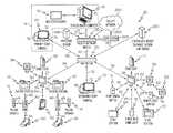
- FIG. 1is a block diagram of a healthcare information system according to this disclosure showing within a dotted L-shaped box a nurse call computer referred to as a primary staff console and a status board computer, each of which is communicatively coupled to multiple hospital beds;
- a nurse call computerreferred to as a primary staff console and a status board computer, each of which is communicatively coupled to multiple hospital beds;
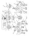
- FIG. 2is block diagram showing various nursing units of a healthcare facility having nurse call computers and status board computers located at master nurse stations of each of the nursing units and communicatively coupled to each other and coupled to other computer devices of a network of the healthcare facility;
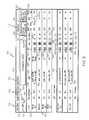
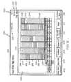
- FIG. 3is a screen shot of an example of a status board screen shown on a display of the status board computer showing for each room in the associated nursing unit information about the patient of each room, the staff assigned to each of the patients, and the status of the hospital bed associated with each of the patients;
- FIG. 4is a screen shot of an example of a Safety Alert History window
- FIG. 5is a screen shot of an example of a Head of Bed Angle History window
- FIG. 6is a screen shot of an example of a Chair Mode History window
- FIG. 7is a screen shot of an example of a Continuous Lateral Rotation (CLRT) Therapy History window
- FIG. 8is screen shot of an example of a Percussion & Vibration (P-V) Therapy History window
- FIG. 9is a screen shot of an example of a Weight History window
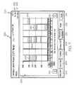
- FIG. 10is screen shot of another example of a status board screen.
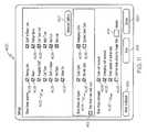
- FIG. 11is a screen shot of an example of a Settings window which is used to select the type of information to be shown on the status board screen.
- the present disclosurerelates to the addition of a status board computer 10 , and optionally, an enlarged status board display screen 12 , to a nurse call system, such as for example, the nurse call system described in U.S. Patent Application Publication Nos. 2009/0212956 A1 and 2009/0217080 A1 which are both hereby expressly incorporated by reference herein.
- the nurse call system described in U.S. Patent Application Publication Nos. 2009/0212956 A1 and 2009/0217080 A1, as well as the nurse call system described hereinpertains to the NaviCare® Nurse CallTM system marketed by Hill-Rom Company, Inc. As will be described in further detail below in connection with FIGS.
- the status board computer 10 and enlarged status board display screen 12if present, provides at one location dynamic information regarding active calls, patient information, staff location, bed status, and/or room status. This information is presented for all of the rooms within one or more hospital units so that information about an entire unit or multiple units is presented to caregivers at a glance.
- a healthcare communication system 20which includes bed status computer 10 also includes a plurality of graphical audio stations 22 and a master station or console 24 which are communicatively coupled as shown diagrammatically in FIG. 1 .
- Many of the stations 22are located in patient rooms and are mounted, for example, to a wall of the respective room or to a headwall unit that, in turn, is mounted to a wall of the respective room.
- Stations 22may be mounted to other architectural support structures, such as service chases or columns just to name a couple.
- Stations 22may be located in other areas of the healthcare facility as well, such as in staff work areas including, for example, hallways and staff lounges.
- stations 22 located in patient roomsmay sometimes be referred to herein as patient stations 22
- stations 22 located in staff work areasmay be sometimes be referred to herein as staff stations 22
- the functionality of stations 22 described hereinis applicable to all stations 22 regardless of whether the station 22 is a patient station 22 or a staff station 22 , unless specifically noted otherwise.
- Patient stations 22communicate bidirectionally (e.g., two-way communication) with a room control board (RCB) circuit 27 which is located within a housing 26 mounted near a dome light assembly 28 .
- RCB circuit 27is sometimes referred to as an input/output (I/O) circuit.
- the bidirectional communicationis indicated diagrammatically in FIG. 1 by double headed arrows 30 .
- two patient stations 22are located in the same hospital room and communicate with a single associated RCB circuit 27 .
- Dome light assemblies 28are typically mounted outside respective patient rooms near the doorways of the rooms and are readily visible to caregivers in the hallway to determine whether any calls or other events indicated on the dome light are occurring within the associated room.
- housings 26 with I/O circuit 27 thereinare mounted generally at these same locations outside patient rooms in some embodiments. However, having housings 26 mounted elsewhere and spaced from dome light assemblies 28 is within the scope of this disclosure.
- dome light assembly 28is, for example, an International Business Machines (IBM) Part No. 43T1899 dome light fixture and I/O circuit 27 is, for example, an IBM part no. 43T2063 IO Board. These IBM part nos. are made specifically for Hill-Rom to be marketed as part of the NaviCare® Nurse CallTM system.
- I/O circuit 27may sometimes be referred to as an I/O board or an I/O circuit board. However, this is not to imply that all circuit components of the circuitry of I/O circuit 27 need to be on a single circuit board, but that is certainly one possibility.
- I/O circuitry 27may be distributed among numerous circuit boards, and in other contemplated embodiments some or all of the components of circuit 27 may not be on any circuit board at all. While illustrative circuit 27 is located in housing 26 , it is within the scope of this disclosure for various components of circuit 27 to be located in separate housings.
- the I/O circuit 27communicates bidirectionally with a Power over Ethernet (PoE) switch 32 as indicated diagrammatically in FIG. 1 by double headed arrow 34 .
- PoE switch 32communicates bidirectionally with master station 24 as indicated diagrammatically by double headed arrow 36 .
- Suitable PoE switchesare available from a variety of suppliers and may include, for example, the PoE switch marketed by Hill-Rom Company, Inc. in connection with its NaviCare® Nurse CallTM system or such as one or more of the various Dell PoE switches marketed under the PowerConnectTM brand name. While only one patient station 22 is shown in FIG.
- system 20may have numerous such patient stations 22 that may communicate with master station 24 via respective I/O circuit boards 27 and via PoE switch 32 .
- bed status computer 10 and master console 24are co-located together at the master nurse call station.
- the bed status computer 10may be located away from the master nurse station at which master console 24 is located.
- bed status computer 10may be located within a hospital administrator's office.
- system 20includes bed connector units 40 , each of which is communicatively coupled to an associated hospital bed 42 as shown diagrammatically in FIG. 1 via lines 44 .
- Bed connector units 40are, in turn coupled to respective patient stations 22 as indicated diagrammatically in FIG. 1 via lines 46 .
- Other arrangements for interconnecting beds 42 with the associated master console 24are described in U.S. Patent Application Publication No. 2009/0212956 A1 which is already incorporated by reference herein.
- beds 42comprise one or more of the beds marketed by Hill-Rom Company, Inc. under the brand names TOTALCARE®, VERSACARE®, ADVANCED-1000TM, CCUIITM and ADVANTATM.
- the illustrative bed connector units 40are also configured to connect to handheld pillow speaker units 41 as indicated diagrammatically via lines 43 .
- FIG. 1includes a facility network switch 90 that communicates bidirectionally with PoE switch 32 as indicated diagrammatically via line 92 .
- Facility network switch 90is shown in FIG. 2 as being coupled to the PoE switches 32 of the various nursing units.
- the bed status computer 10 located at one nursingis able to display data pertaining to other nursing units.
- two of the nursing unitshave bed status computers 10 , each with an associated enlarged bed status board display 12 , and one of the nursing units does not have any bed status computer 10 or associated display 12 .
- the two bed status computers 10each communicate with an associated PoE switch 32 as indicated by dotted lines 94 .
- both of the bed status board computers 10are able to receive an display data from any of the three nursing units that are illustrated in FIG. 2 . Accordingly, it is not necessary that each and every nursing unit of a healthcare facility have a bed status computer 10 although that is certainly within the scope of this disclosure.
- bed status computers 10may not communicate with associated PoE switches, but instead may communicate directly with the facility network switch 90 . Such an alternative is shown in FIG. 1 in which bed status computer 10 communicates bidirectionally with facility network switch 90 as indicated diagrammatically with line 94 .
- a wall-mounted nurse call switch 52which may be mounted in a lavatory of the patient room, for example, is coupled to the circuit board 27 of assembly 28 as indicated diagrammatically by double-headed arrow 54 .
- a wireless receiver 56which illustratively is an infrared receiver that receives wireless signals from locating-and-tracking badges 58 , shown in FIG.
- Wireless receivers 56are sometimes referred to as room location receivers (RLR).
- RLRroom location receivers
- RLR's 56are daisy chained together such that one of the RLR's 56 communicates with circuit 27 via another of the RLR's 56 .
- a first staff station 22communicates bidirectionally with an associated RCB circuit 27 via a communications link 68 and a second staff station 22 communicates bidirectionally directly with PoE switch 32 via a communications link 70 .
- the first staff station 22is mounted to a wall, for example, whereas the second staff station 22 has a graphical display screen module 72 connected to a base module 74 which includes a telephone hand set 76 .
- the master station 24 shown in the FIG. 1 examplealso has a graphical display screen module 72 connected to a base module 74 which has a telephone handset 76 .
- the first staff station 22is in communication with PoE switch 32 via the RCB 27 and associated communication link 34 .
- Some further exemplary devices coupled to RCB circuit 27 in the FIG. 1 exampleinclude a staff emergency switch 71 , a simplified staff station 124 (aka a Standard Room Station or SRS), a single-bulb dome light 73 , a remote code switch 75 , and a zone light 77 .
- Each of these further devices 71 , 73 , 75 , 77 , 124is shown communicating bidirectionally with RCB 27 via diagrammatic lines 81 .
- master consoles 24 and staff consoles 22 having display 72 coupled to base 74are model number GRS-10 devices available from Hill-Rom Company, Inc.
- patient stations 22 and staff stations 22 that are not coupled to base 74are model number GRS-5 devices available from Hill-Rom Company, Inc.
- the simplified staff station 124may be IBM part no. 43T2082 which is available from Hill-Rom Company, Inc. as model number SRS.
- FIG. 2 exampleshows that a personal computer 78 may cooperate with the associated display screen module 72 to provide the master station functionality.
- personal computer 78is the only computer device included in master station 24 while, in still other embodiments such as the one of FIG. 1 , personal computer 78 is omitted.
- a graphical display module 72can serve as a patient station 22 , a staff station 22 or as a master station 24 .
- module 72can be coupled to base module 74 , if desired.
- the display screen of module 72is approximately a 10 inch display screen in some embodiments and therefore is larger than the LCD screen used in, for example, the COMLINX® system.
- Each of the communications links 30 , 34 , 36 , 38 , 44 , 46 , 54 , 60 , 62 , 66 , 68 , 70 , 81 , 92 , 94 shown diagrammatically by lines or arrows in FIGS. 1 and 2 , as well as any other communications links described herein,may include wired links and/or wireless links and/or combinations thereof, along with associated connectors.
- links 44 between beds 42 and bed connector units 40known cables having 37-pin connectors (or similar connectors) may provide these links 44 .
- links 44may be wireless links, in which case, the respective beds 42 and units 40 have appropriate wireless transmitter and wireless receiver circuitry, which may be in the form of a wireless transceiver.
- wireless communication between beds 42 and units 40is discussed, for example, in U.S. Pat. No. 7,319,386 and in U.S Patent Application Publication No. 2007/0210917 A1, both of which are hereby incorporated herein by this reference.
- the communication protocol for links 30 , 34 , 36 , 38 , 44 , 46 , 54 , 60 , 62 , 66 , 68 , 70 , 81 , 92 , 94may be according to any suitable protocol such as the TCP/IP protocol, the RS-232 protocol, the RS-422 protocol, the RS-423 protocol, or the RS-485 protocol, or similar such protocols, and such as wireless protocols including any of the IEEE 802.11 x protocols (where x represents the various revision levels a, b, c, d, e, g and so forth of the 802.11 protocol), the Bluetooth protocol, the Zigbee protocol, or similar such wireless communication protocols.
- any suitable protocolsuch as the TCP/IP protocol, the RS-232 protocol, the RS-422 protocol, the RS-423 protocol, or the RS-485 protocol, or similar such protocols, and such as wireless protocols including any of the IEEE 802.11 x protocols (where x represents the various revision levels a, b,
- the Palmetto protocol described in U.S. Patent Application Publication Nos. 2009/0212956 A1is used as the communication protocol for the data sent one or more links 30 , 34 , 36 , 38 , 44 , 46 , 54 , 60 , 62 , 66 , 68 , 70 , 81 , 92 , 94 .
- links 30 , 44 , 46 , 54 , 62which are the communications links associated with a patient room that communicate between devices in the patient room and the I/O circuit board 27 of dome light assembly 28 , are according to the RS-485 protocol, whereas links 34 , 36 , 68 , 70 , 92 which are the links to and from PoE switches 32 , are according to the TCP/IP protocol.
- the devices that communicate over these various linksare configured and programmed appropriately for the required RS-485 or TCP/IP protocol, as the case may be.
- the circuitry of I/O circuit 27operates to convert the data from these various devices according to their device-specific communication protocols (e.g., serial links to stations 124 ; locating and tracking receivers 56 room bus protocol; bed connector 40 room bus protocol; and serial to dome light protocol) into the TCP/IP protocol for subsequent transmission to the PoE switch and ultimately to the master station 24 and to other network devices, if desired.
- device-specific communication protocolse.g., serial links to stations 124 ; locating and tracking receivers 56 room bus protocol; bed connector 40 room bus protocol; and serial to dome light protocol
- stations 22 , 24each have graphical displays
- stations 124are a low cost offering that don't have any graphical display but that provide call cancel, call placement, reception for signals from locating badges 58 and voice communication functionality.
- Stations 124connect to the I/O circuit board of assembly 28 via an RS-485 connection.
- Stations 124can be configured as a patient station, staff station, or visitor station.
- the components of system 20 which cooperate to provide a healthcare facility with a nurse call systemare referred to collectively as a “base nurse call system.”
- stations 22 , 122 and I/O circuit 27 , dome light assemblies 28 , and any of the equipment described above that is capable of providing a nurse call signal, as well as the associated master station 24 and PoE switches 32 along with any of the communication links interconnecting these componentsare among the components which comprise a “base nurse call system” according to this disclosure.
- Staff stations 22if present, are also considered to comprise part of the base nurse call system.
- Base nurse call systemsare subject to Underwriter's Laboratories UL-1096 requirements.
- the bed status board computer 10 and, if present, the associated enlarged bed status board display screen 12are not part of the base nurse call system and so are not subject to the UL-1096 requirements.
- the bed status board computer 10 and optional screen 12provide caregivers with some of the same information that the base nurse call system provides to caregivers.
- some of the information displayed on the monitor of bed status board computer 10 and/or screen 12is redundant to information that may be displayed on screen 72 of master station 24 .
- the components of the base nurse call system of illustrative system 20are compliant with the Underwriter's Laboratories 1069 standard according to this disclosure, this is not to imply that the components of the base nurse call system may not also be compliant with other standards relating to nurse call systems or relating to some other aspect of these devices.
- the bed status board computer 10 and, if present, the associated enlarged bed status board display screen 12are part of the base nurse call system and so are compliant with UL-1096 requirements.
- the bed status computer 10is coupled to the same PoE switch 32 that the master console 24 rather than being coupled to the network facility switch 90 .
- the reporting server 268may also be coupled to the PoE switch 32 rather than the facility network switch 90 . It is contemplated by this disclosure that the functionality of status board computer 10 and master console 24 can be merged into a single computer device.
- status board computer 10may be configured to permit a nurse at the master station to answer nurse calls via the status board computer 10 and master console 24 may, in turn, be omitted.
- Such a capabilityis facilitated at computer 10 , in some embodiments, by use of voice over Internet Protocol (VoIP) communications technology and software.
- VoIPvoice over Internet Protocol
- a Voice over Internet Protocol (VoIP) sever 250is also included in the base nurse call system and is coupled to PoE switch 32 via a TCP/IP communications link 252 as shown diagrammatically in FIG. 1 .
- Server 250facilitates communication between which ever of stations 22 , 24 , 124 are present in the system 20 .
- Server 250is configured to translate system operations and communications to the corresponding messages that then control endpoint devices, such as stations 22 , 124 , consoles 24 , or room input/output circuits 27 .
- server 250may include a soft telephony switch and other associated components in some embodiments.
- Server 250may also provide integration with the hospital telecommunications structure (not shown), although some other server may do so as well.
- the healthcare communication system 20includes a facility network or Ethernet 260 that communicates with facility network switch 90 via a bidirectional communications link 262 .
- Facility network 260includes all of the various other computer devices (not shown), hardware (not shown), and software (not shown) that those skilled in the art typically consider as comprising an Ethernet of a healthcare facility.
- the components shown in FIGS. 1 and 2such as computer 10 , stations 22 , 24 , 124 , RCB 27 , server 250 are also considered to be part of the facility network of system 20 .
- the facility network 260 “cloud” shown in FIGS. 1 and 2is intended to be representative of all of the parts of any given healthcare system 20 that are not specifically described herein.
- an admission, discharge, and transfer (ADT) system 264is shown communicating via a bidirectional communications link 266 with facility network 260 .
- bed status computer 10receives patient information from the ADT system 264 via network 260 , network switch 90 , and the associated communications links 92 , 94 , 262 , 266 .
- a reporting server 268is coupled to facility network switch 90 via a bidirectional communications link 271 .
- the reporting server 268serves as a data repository for bed data emanating from patient beds 42 and bed status computer 10 obtains data from the reporting server for populating the information on the various screens shown in FIGS. 3-10 , for example.
- Reporting server 268may receive data from other sources, such as for example, an Electronic Medical Records (EMR) system in some embodiments, and reporting server 268 may be included as part of an EMR system in some embodiments.
- EMRElectronic Medical Records
- serverWhile the term “server” is used herein, it will be understood by those skilled in the art that the functionality represented or performed by devices referred to as “severs” may comprise and be performed by any suitable computer device having software programs or services that may be resident and/or executable by any computer, device or equipment in the system or more than one computer, device or equipment in the network. Thus, there term “server” is intended to broadly encompass any computer device that is capable of performing the mentioned functions.
- an example of a status board screen 100 which is shown on a display or monitor 15 of the status board computer 10includes a header bar 102 that has a Status Board icon 104 , a Hospital Administration icon 106 , a System Views icon 108 and an Anonymous identifier 110 .
- Header bar 102is shown on display 15 at all times that the bed status computer system is operating to permit the user to navigate to the main portion of the system.
- computer 10responds with status board screen 100 which is discussed in further detail below.
- computer 10When Hospital Administration icon 106 is selected, computer 10 responds with an administration screen (not shown) that permits a hospital administrator to enter a user name and password to gain access to various other screens to set up new users of the system, for example.
- administration screen(not shown) that permits a hospital administrator to enter a user name and password to gain access to various other screens to set up new users of the system, for example.
- such other screensalso permit the administrator to add caregivers to the list of assignable caregivers and to assign particular caregivers to patients and/or to rooms in the nursing unit.
- the caregiver assignments to patients and/or roomsare made using the associated master console 24 and then that data is communicated to bed status computer 10 so that the assignment information can be properly shown on screen 100 .
- the Anonymous identifier 110 shown in header bar 103simply indicates that the a user with the user name “Anonymous” has logged into the bed status system which includes computer 10 .
- the Anonymous identifier 110is replaced under such circumstances by the particular user's user name.
- a display control area bar 112appears beneath header bar 102 but above a main table 122 .
- Illustrative display control area bar 112includes a Unit A identifier 114 , a Unit Selector icon 116 , a Dynamic Message Area box 118 , and a Calls Selection menu 120 .
- the Unit A identifier 114indicates the user has selected to view the data associated with Unit A. If the user selects the Unit Selector icon 116 , then computer 10 responds with a drop down menu in the vicinity of icon 116 that has a list of the nursing units that may be view on status board screen 100 .
- a drop down menumay include a list such as Unit A, Unit B, Unit C, All Units. The user then selects in the drop down menu the unit or units for which the user desired the data to be displayed on screen 100 .
- the Dynamic Message Area box 118shows any calls that have been received from any of the rooms in the nursing unit or units selected using icon 116 . If there are multiple calls and multiple call types, then the calls are prioritized and appear in Dynamic Message Area box 118 in the following manner. More specifically, if more than one call exists, the viewable message in box 118 will rotate using a vertical scrolling marquee technique. In connection with scrolling through the calls, each message will be visible for a threshold amount of type, such as about 8 seconds in one embodiment, before rotating out to show the next message. However, if one or more code call exists, then the list of messages that appear in box 118 are limited to the code call(s). Code calls typically are made when a patient goes into cardiac arrest.
- System Alert callswhich relate to, for example, an error condition in a piece of equipment, do not count toward the total number of calls and are not displayed in box 118 .
- the System Alert callsare shown in box 118 along with the regular or normal calls.
- Bed Disconnect alertswhich indicate that a bed 42 has been disconnected from its respective bed connector unit 40 , do not count toward the total number of calls and are not displayed in box 118 .
- the Bed Disconnect alertsare displayed in box 118 along with the regular or normal calls.
- the amount of time that has elapsed since a particular call has been placedcan be included in box 118 during the time that the associated call or alert is displayed in box 118 .
- the message “1 Critical Call (0:37)”appears in box 118 to indicate that 37 seconds have elapsed since the critical call was placed.
- the Critical Callis a Code Blue call from room 305 as indicated by highlighting 126 around the associated line in the main table 122 of screen 100 .
- the text “Normal—Cardiology, Room 101 has been waiting for 32:45 min”is another example of the type of information that may be displayed in box 118 in some embodiments.
- the amount of time that has elapsedis referred to as a Call Threshold Indicator and may be a number that is preprogrammed or that is preselected by a hospital administrator.
- a Call Threshold Indicatormay be set at 15 minutes.
- Calls selection menu 120includes a set of choices that are selectable by the user of computer 10 to indicate which types of calls and/or alerts are to be shown within box 118 .
- menuincludes the following choices: “Critical Call View;” “Code Calls;” “Emergency Calls;” “Show Only Calls;” “Normal Calls;” and “System Alerts.”
- An indicator box 128appears next to each choice of menu 120 .
- indicator boxes 128 associated with the “Code Calls;” “Normal Calls;” and “System Alerts” menu itemsare filled in to indicate that the user has selected these types of calls to appear in box 118 .
- the main table 122indicates all of the types of calls that may occur in any of the rooms in the unit such that the information appearing in box 118 is redundant to information that otherwise can be seen on main table 122 .
- Main table 122occupies the majority of screen 100 and includes rows that correspond to each room in the nursing units that have been selected via icon 116 for display. In the illustrative example in which Unit A is the only nursing unit chosen for display, there is a row for each room 300 - 308 that is included in the nursing unit. If there are more rooms in a nursing unit than are able to fit onto the viewing area of main table 122 , then a scroll bar appears at the left or right side of table 122 to permit the user to scroll down to see the additional rooms.
- Main table 122includes the following columns of information: a Call column 130 ; a Room column 132 ; a Patient column 134 ; a Staff column 136 ; a Risk column 138 ; a Bed Exit column 140 ; a Rails column 142 ; a Low column 144 ; a Brake column 146 ; a Rounds Due column 148 ; a Turn Assist column 150 ; a Head of Bed (HOB) column 152 ; and a Weight (kg) column 154 .
- a Call column 130includes the following columns of information: a Call column 130 ; a Room column 132 ; a Patient column 134 ; a Staff column 136 ; a Risk column 138 ; a Bed Exit column 140 ; a Rails column 142 ; a Low column 144 ; a Brake column 146 ; a Rounds Due column 148 ; a Turn Assist column 150 ; a Head of Bed (HOB) column 152 ; and
- Call column 130shows the type of call, if any, that has been placed or that has otherwise been detected for each room in the unit.
- a clock in minutes:seconds formatto indicate the amount of time that has elapsed since the associated call was placed or detected.
- Normal callswere placed from each of rooms 300 , 302 , and 303 thirty seconds ago
- Rails callwere detected in rooms 301 and 307 twenty-three second ago
- a Code Blue callwas placed from room 305 eleven seconds ago.
- the illustrative exampleprovides a somewhat unrealistic scenario in that it is unlikely that patients in three rooms would place a Normal call, such as by pressing the nurse call button on a bed siderail or on a pillow speaker, at exactly the same time and it is unlikely that patients or caregivers in two rooms would lower one or more bed siderails at exactly the same time. It should be noted that, in the illustrative example, no calls of any type exist with regard to rooms 304 , 306 and 398 .
- the Room column 132shows the number of the room associated with each row of information.
- An ascending/descending sort icon 156illustratively a triangle, appears next to the word “Room” in the column 132 heading.
- Icon 156can be selected to change the sort from ascending to descending and vice versa.
- the room numbersare sorted into ascending order. That is, the room numbers go up from 300 to 308 down the table 122 . If the room numbers were sorted in descending order, they would go down from 308 to 300 down the table.
- other sorting techniques for the data appearing on monitor 15 of computer 10 and/or on display screen 12are contemplated by this disclosure.
- Room column 132includes either “A” and “B” indicators appended to the two-patient room numbers (e.g., 101 A and 101 B) or “-1” and “-2” indicators appended to the two-patient room numbers (e.g., 101 - 1 and 101 - 2 ) or some similar such nomenclature scheme.
- the Patient column 134shows, for each of the rooms that contain a patient, a patient identifier in a HIPAA compliant format.
- a partial patient nameis shown by indicating the first two letters of the patient's last name followed by a set of ellipses and the first letter of the patient's first name.
- the row associated with room 304has the text “Room Ready” in the Patient column 134 . This indicates that no patient is in the room currently but the room is ready to receive a patient.
- the row associated with room 308has the text “Not Ready” in the Patient column 143 .
- a caregivermay enter certain information on the patient station 22 located in the associated patient room as discussed in further detail in U.S. application Ser. No. 12/708,891, filed Feb. 19, 2010, which is titled “Patient Room and Bed Management Apparatus and System” and in U.S. application Ser. No. 12/711,912, filed on the same date as the present application, which is also titled “Patient Room and Bed Management Apparatus and System” and both of which are hereby expressly incorporated by reference herein.
- the usercan change the status of a particular room from “Not Ready” to “Room Ready” using the bed status computer 10 .
- the Staff column 136lists the names of the caregivers who are assigned to patients in each of the rooms. As can be seen in FIG. 3 , some patients have two assigned caregivers and others only have one assigned caregiver. In the illustrative example, the caregiver names are listed in last name, first name format. A parenthetical abbreviation follows the caregiver name to indicate the caregiver's role. For example, RN is the abbreviation for registered nurse and LPN is the abbreviation for licensed practical nurse.
- Staff column 136also includes an icon 158 , illustratively a square, to indicate whether or not a caregiver is present in the patient room. In the example of FIG. 3 , caregivers are present in rooms 300 , 305 , and 307 .
- computer 10receives information form a locating and tracking system of the healthcare facility in order to determine whether icon 158 is to be shown on screen 100 in the Staff column 136 of a particular row.
- the locating and tracking systemincludes, for example, badges 58 and room locating receivers 56 which are described above.
- the locating and tracking informationis stored in reporting server 268 in some embodiments.
- the Risk column 138indicates within each row of table 122 whether the associated patient has been identified as having a particular type of risk.
- patients in rooms 301 - 303 and 305 - 307have each been identified as having a “Fall” risk. If a patient is considered a Fall risk, then typically it is not desirable for that patient to get out of bed unless a caregiver is present in the room to assist the patient. Accordingly, for Fall risk patients, an alert condition will be considered to exist if any of the bed siderails are moved to a lowered position or if the patient exits the bed.
- bed status computer 10is able to indicate multiple risk types on table 122 for particular patients if necessary.
- a patient indicated as a “Skin” riskthen this typically means that the patient has a higher than normal risk of developing bed sores or pressure ulcers.
- a patient identified as a “Priority” riskmeans that the patient likely requires more nursing attention than other patients on the unit.
- the information indicating that a patient is a particular risk typemay come from a number of sources.
- the informationmay be entered by a user of computer 10 in some instances and may be transmitted to computer 10 and/or reporting server 268 from another portion of system 20 such as ADT system 264 or an EMR system.
- the Risk column 138 of table 122may be auto-populated with risk data that originates from another portion of system 20 .
- the risk namessuch as Falls and/or Lungs
- a color coding of greenmeans that the associated monitoring is turned on
- a color coding of yellowmeans that the associated monitoring is turned off
- a color coding of redmeans that at least one of monitored conditions associated with the particular risk name is alarming.
- beds 42may have a button or other user input to turn the safety alerting on, to turn the safety alerting off, and/or to suspend or silence the safety alerting.
- a user input to turn the safety alerting on and/or off, or to suspend or silence the safety alertingmay be provided on patient stations 22 .
- patient stations 22may have one or more touch screen buttons for one or more of these purposes.
- the Bed Exit column 140indicates whether or not a bed exit system of the hospital bed 42 associated with the patient of each row of table 122 is armed, at what level it is armed, and whether a bed exit alarm is occurring.
- a patient position mode icon 160appears in column 140 as shown in table 122 with regard to rooms 301 , 302 and 305 - 307 .
- a bed exiting mode icon 162appears in column 140 as shown in table 122 with regard to room 303 .
- an out-of-bed mode icon 164appears in column 140 as shown in table 122 with regard to room 300 .
- Column 140also includes an alarm on/off indicator 164 , illustratively a square, to indicate whether or not a bed exit alarm is occurring. If a bed exit alarm is occurring, then the alarm on/off indicator 164 becomes highlighted as shown in table 122 with regard to room 306 , for example.
- the data shown in column 140is based on information transmitted from the beds 42 located in the patient rooms of the nursing unit for which the information viewed on monitor 15 and/or display screen 12 is associated.
- the bed exit systemsare typically armed by caregivers at the bedside by manipulating the appropriate bed exit user interface devices, such as buttons or touch screen, found on the individual beds. However, it is within the scope of this disclosure for the bed exit systems of beds 42 to be armed via some other user input device or computer device such as stations 22 , 24 .
- the Rails column 142indicates for each of the hospital beds 42 in each of the patient rooms, whether the siderails of the bed are in a raised position or in a lowered position.
- four indicators 166which illustratively are squares are provided in each row with each individual square 166 corresponding to one of the four siderails of the associated hospital bed 42 .
- the Low column 144includes an indicator 168 , illustratively a square, for each of the hospital beds 42 in each of the patient rooms which indicates whether an upper frame of the bed 42 is in its lowest position relative to a base frame of the bed 42 . If the upper frame of a particular bed is not in its lowest position, then the icon 168 becomes highlighted as is shown for icons 168 associated with rooms 301 and 305 in column 144 of table 122 . If the upper frame of a particular bed is in its lowest position, then the icon 168 remains unhighlighted as is shown for the icons 168 associated with rooms 300 , 302 , 303 , 306 and 307 in column 144 of table 122 .
- the data shown in column 144is based on information transmitted from the beds 42 located in the patient rooms of the nursing unit for which the information viewed on monitor 15 and/or display screen 12 is associated.
- the Brake column 146includes an indicator 170 , illustratively a square, for each of the hospital beds 42 in each of the patient rooms which indicates whether the caster brakes of the bed 42 are braked. If the casters of a particular bed are not braked, or to put it another way, if the casters of a particular bed are released, then the icon 170 becomes highlighted as is shown for icons 170 associated with rooms 301 and 307 in column 146 of table 122 . If the casters of a particular bed are braked, then the icon 170 remains unhighlighted as is shown for the icons 170 associated with rooms 300 , 302 , 303 , 3065 and 306 in column 146 of table 122 .
- the data shown in column 144is based on information transmitted from the beds 42 located in the patient rooms of the nursing unit for which the information viewed on monitor 15 and/or display screen 12 is associated.
- the Rounds Due column 148includes, for each row corresponding to a patient in table 122 , a countdown timer or clock to indicate when the next rounds are due for the associated patient.
- a “round”is considered to be a scheduled visit by an assigned caregiver to the patient's room regardless of whether any call has been placed or any alert condition detected.
- the countdown timer or clockis illustratively shown in a minutes:seconds format.
- the rounds for each of the patient roomsis scheduled 5 minutes apart. Thus, for room 300 , the next round is due in 15 minutes, 15 seconds; for room 301 , the next round is due in twenty minutes, fifteen seconds; and so on.
- the time interval between rounds to a particular patientcan be set by the user with computer 10 or can be based on information transmitted from some other portion of system 20 such as the ADT system or EMR system for example. Also, the time allotted for a caregiver to be in a room during the scheduled visit can be set by the user with computer 10 or can be based on information transmitted from some other portion of system 20 such as those mentioned above.
- the Turn Assist column 150includes, for particular rows corresponding to one or more selected patients in table 122 , a countdown timer or clock to indicate when the next turn of the patient is to occur.
- a turn of patientmeans rolling the patient from their back to either their right or left side or vice versa, or rolling the patient from their left side to their right side.
- Some hospital beds 42have a turn assist function in which a left turn assist bladder or a right turn assist bladder is inflated on a one-time basis for a short period of time to assist a caregiver in turning the patient either toward the left or toward the right as the case may be.
- the countdown timer or clock in column 150is illustratively shown in a minutes:seconds format.
- the a turn assist for the patient in room 300is scheduled to occur in 15 minutes, 15 seconds.
- the time interval between turn assists of a particular patientcan be set by the user with computer 10 or can be based on information transmitted from some other portion of system 20 such as the ADT system, the EMR system, or a computerized physician's order system, for example.
- the Head of Bed (HOB) column 152indicates for each hospital bed 42 associated with a patient of a corresponding row of table 122 , the angle at which a head section of the bed is elevated with respect to horizontal or with respect to an upper frame of the bed 42 .
- the bed 42 in room 300has its head section raised by 35 degrees
- the bed 42 in room 301has its head section raised by 30 degrees
- the data shown in column 152is based on information transmitted from the beds 42 located in the patient rooms of the nursing unit for which the information viewed on monitor 15 and/or display screen 12 is associated.
- the Weight (kg) column 154indicates the weight of each patient associated with a corresponding row of table 122 as measured by a weight scale system of the respective bed 42 .
- each of the weights in column 154is in the units of kilograms.
- Computer 10can be used to change the weight units to pounds in some embodiments.
- the data shown in column 154is based on information transmitted from the beds 42 located in the patient rooms of the nursing unit for which the information viewed on monitor 15 and/or display screen 12 is associated.
- the weight scale systems of many beds 42permit caregivers to select whether the weight measurement is displayed at the bed in pounds or kilograms. Thus, there is a chance that some beds in a unit are set to display weight in pounds and others are set to display weight in kilograms.
- computer 10is configured to convert weight in pounds to weight in kilograms if column 154 is set to display weight in kilograms and computer 10 is configured to convert weight in kilograms to weight in pounds if column 154 is set to display weight in pounds.
- the weights shown in column 154may have the same units as received from the associated bed 42 in which case, the pounds (lb) or kilogram (kg) units designators appear next to each of the weights in column 154 .
- a Safety Alert History window 200an example of which is shown in FIG. 4 .
- the information in the windows of FIG. 4-9pertain to the patient associated with the row that the user highlighted or selected on table 122 of screen 100 .
- Window 200is the default window that appears upon selection of icon 108 .
- Window 200actually appears over a portion of table 122 such that the header bar 102 and display control area bar 112 can still be seen above window 200 on monitor 15 and/or display screen 12 .
- a Safety Alerts tab 202Along the bottom of window 200 are a Safety Alerts tab 202 , a Head of Bed tab 204 , a ChairMode tab 206 , a Rotation (CLRT) tab 208 , a Percussion & Vibration tab 210 , a Weight tab 212 , and a cancel button 214 .
- CTRRotation
- Header area 216has a header area 216 with the “Safety Alert History” title appearing on the left-hand side. Header area 216 also includes the patient's name 218 but not in a HIPAA compliant format. In other embodiments, the patient's name is shown in header area 216 in a HIPAA compliant format. Header area 216 further includes on the right hand side the patient's room number 220 and any risk categories 222 designated for the patient as discussed above. In the illustrative example, the patient's name 218 is John Patient, the patient's room number 220 is 213 -A, and the patient's risk categories are “No Falls” and “Clear Lungs.”
- Beneath header area 216 in window 200is a History table 224 .
- History table 224has a number of rows in which are shown the date and time that various bed alerts have been detected.
- a Rails alertoccurred on Feb. 28, 2009 at 1:54 pm
- a Bed Exit alertoccurred on Feb. 28, 2009 at 11:34 am
- a Brakes alertoccurred on Feb. 27, 2009 at 9:56 pm
- another Rails alertoccurred on Feb. 26, 2009 at 4:20 pm.
- Next to table 224are an up arrow icon 226 and a down arrow icon 228 which are used to scroll up and down the rows of table 224 if there are more rows of information than can fit on table 224 at the same time.
- the Alert History for each patientis stored in memory for the duration of their stay at the healthcare facility as determined by information obtained from or sent from the ADT system.
- the alerts information for the patientis stored in computer 10 and/or reporting server 268 but, in some embodiments, is erased as a result of the patient's discharge.
- computer 10 and server 268do not permanently maintain the alerts information in the way that an EMR system computer may.
- computer 10 and/or server 268it is within the scope of this disclosure for computer 10 and/or server 268 to communicate the alerts information to the EMR system for longer term storage.
- some or all of the data associated with the Alert History for each patientmay continue to stored in server 268 and/or computer 10 for a longer period of time after an associated patient's discharge.
- reportscan be generated using computer 10 and/or server 268 to determine protocol compliance over time.
- Healthcare facilitiescan determine their performance trends, such as with regard to safety protocol compliance, over time by studying such information.
- computer 10 and/or server 264may be used for one or more of these purposes in some embodiments.
- manual admit and discharge functionscan be performed manually using the keyboard of computer 10 .
- Such admit and/or discharge information entered via computer 10may be used only locally in connection with the information being gathered and displayed by computer 10 , in which case the ADT system 264 still may need to be used for entry of patient admit and discharge information for other purposes.
- the admit and/or discharge information entered at computer 10is communicated to other computer devices of facility network 260 including computer devices of the ADT system 264 such that no additional patient admit and/or discharge information needs to be entered by caregivers elsewhere within the network 260 .
- Window 200also includes a Bed Alerts Active/Suppress icon 230 that is selected to turn on or turn off whether alerts relating to bed status (e.g., siderail position, caster brake status, bed height) are to be displayed on screen 100 when they occur for the particular patient 218 listed in header area 216 .
- the usersimply selects the bed alerts icon 230 to toggle been the active and suppress functions.
- Window 200further has a bed icon 232 that provides a graphical image of the current status of the bed associated with the patient 218 listed in header area 216 .
- the graphical appearance of icon 232mimics the positions of the siderails of the bed and uses color coding such as green and red to indicate the status of bed height and caster brake statuses.
- Head of Bed Angle History window 240an example of which is shown in FIG. 5 .
- Window 240includes the same information in header area 216 as window 200 except that the title on the left hand side of header area 216 is changed to “Head of Bed Angle History.”
- Window 240has a head of bed angle graph 242 which has columns that correspond to each day of the associated patient's stay at the healthcare facility and that graphically indicates in each column for each day the ranges within which the angle of the head section of the patient's bed 42 was positioned.
- the rangesare color coded to indicate whether the head section of the bed is above 30 degrees of elevation, above 45 degrees of elevation, or in an alert condition which, in some embodiments, is above 60 degrees of elevation.
- the color codingincludes green blocks 244 for indicating that the head section was above 30 degrees of elevation, blue blocks 246 for indicating that the head section was above 45 degrees of elevation, and yellow blocks 248 for indicating that the head section was in an alert condition.
- Other color coding schemes and other graphical representation schemescan be used if desired.
- Beneath each column of graph 242are blocks of information to indicate the date, the duration of time during the 24 hour period of the associated date that the head section of the bed was above 30 degrees, and the duration of time during the 24 hour period that the head section of the bed was above 45 degrees. In some embodiments, an additional block of information is provided to indicate the amount of time during the 24 hour period that the head section of the bed was in an alert condition.
- graph 242is constructed by computer 10 based on the head of bed angle information that originates at the associated patient bed 42 .
- the historical head of bed informationmay be stored in memory of computer 10 and/or reporting server 268 .
- the head of bed angle history data used to construct graph 242begins to be stored in response to receipt of admission data for the patient from the ADT system 264 and ceases to be stored in response to receipt of discharge data for the patient from the ADT system 264 .
- a userselects ChairMode tab 206 , computer 10 responds with a Chair Mode History window 270 an example of which is shown in FIG. 6 .
- Window 270includes the same information in header area 216 as windows 200 , 240 except that the title on the left hand side of header area 216 is changed to “Chair Mode History.”
- Window 270has a chair mode graph 272 which has columns that correspond to each day of the associated patient's stay at the healthcare facility and that graphically indicates in each column for each day the times during which the patient's bed 42 was placed in a chair position.
- the chair positionrefers to a position in which the head section of bed 42 is raised and the foot section of bed 42 is lowered to place a mattress support deck in a chair like configuration.
- the times during which the bed 42 is in the chair positionare color coded in graph 272 .
- the color codingincludes green blocks 274 for indicating that the bed 42 was in the chair position.
- Other color coding schemes and other graphical representation schemescan be used if desired.
- Beneath each column of graph 272are blocks of information to indicate the date, the duration of time during the 24 hour period of the associated date that the bed 42 was in the chair position, and whether any alarm associated with the chair position occurred. It will be appreciated that graph 272 is constructed by computer 10 based on information that originates at the associated patient bed 42 to indicate whether the bed is in the chair position. The historical chair position information may be stored in memory of computer 10 and/or reporting server 268 . The chair position data used to construct graph 272 begins to be stored in response to receipt of admission data for the patient from the ADT system 264 and ceases to be stored in response to receipt of discharge data for the patient from the ADT system 264 .
- a left scroll icon 276 and a right scroll icon 278are provided near the bottom of window 270 to permit a user to scroll to days that are earlier in time or later in time, respectively, than those currently shown in window 270 .
- CRTContinuous Lateral Rotation Therapy
- Window 280includes the same information in header area 216 as windows 200 , 240 , 270 except that the title on the left hand side of header area 216 is changed to “Continuous Lateral Rotation (CLRT) Therapy History.”
- Window 280has a CLRT graph 282 which has columns that correspond to each day of the associated patient's stay at the healthcare facility and that graphically indicates in each column for each day the times during which a mattress on the patient's bed 42 was operating in a CLRT mode.
- the CLRT mode of a mattressrefers to a therapy in which rotation bladders on the left side of the mattress and the right side of the mattress are continuously and alternately inflated and deflated to turn the patient repeatedly to their right and to their left.
- the times during which the mattress of bed 42 is in operated in the CLRT modeare color coded in graph 282 .
- the color codingincludes green blocks 284 for indicating that the mattress of bed 42 was operating in the chair CLRT mode. Other color coding schemes and other graphical representation schemes can be used if desired.
- Beneath each column of graph 282are blocks of information to indicate the date, the duration of time during the 24 hour period of the associated date that the mattress of bed 42 was operating in the CLRT mode, and whether any alarms associated with the CLRT mode occurred. It will be appreciated that graph 282 is constructed by computer 10 based on information that originates at the associated patient bed 42 to indicate whether the bed is in operating in the CLRT mode.
- the historical CLRT mode informationmay be stored in memory of computer 10 and/or reporting server 268 .
- the CLRT mode data used to construct graph 282begins to be stored in response to receipt of admission data for the patient from the ADT system 264 and ceases to be stored in response to receipt of discharge data for the patient from the ADT system 264 .
- window 280includes left scroll icon 276 and right scroll icon 278 that are used in the same manner as described above to scroll to additional days of information.
- Percussion & Vibration (P-V) History window 290an example of which is shown in FIG. 8 .
- Window 290includes the same information in header area 216 as windows 200 , 240 , 270 , 280 except that the title on the left hand side of header area 216 is changed to “Percussion & Vibration (P-V) Therapy History.”
- Window 290has a P-V graph 292 which has columns that correspond to each day of the associated patient's stay at the healthcare facility and that graphically indicates in each column for each day the times during which a mattress on the patient's bed 42 was operating in either a percussion mode or a vibration mode.
- the percussion and vibration modes of a mattressrefers to a therapy in which P-V bladders of the mattress are vibrated or percussed.
- the times during which the mattress of bed 42 is in operated in the P-V modesare color coded in graph 282 .
- the color codingincludes green blocks 294 for indicating that the mattress was operating in the percussion mode, blue blocks 296 for indicating that the mattress was operating in the vibration mode, and yellow blocks 298 for indicating that at least one of the P-V modes was in an alert condition.
- Other color coding schemes and other graphical representation schemescan be used if desired.
- Beneath each column of graph 282are blocks of information to indicate the date, the duration of time during the 24 hour period of the associated date that the mattress of bed 42 was operating in the percussion mode, the duration of time during the 24 hour period of the associated date that the mattress of bed 42 was operating in the vibration mode, and whether any alarms associated with the P-V modes occurred.
- graph 292is constructed by computer 10 based on information that originates at the associated patient bed 42 to indicate whether the bed is in operating in one of the P-V modes.
- the historical P-V mode informationmay be stored in memory of computer 10 and/or reporting server 268 .
- the P-V mode data used to construct graph 292begins to be stored in response to receipt of admission data for the patient from the ADT system 264 and ceases to be stored in response to receipt of discharge data for the patient from the ADT system 264 . It is contemplated by this disclosure that a similar type of graph can be constructed for other types of therapies associated with beds 42 .
- One example of another time of therapyis alternating pressure (AP) therapy.
- APalternating pressure
- Weight History window 300includes the same information in header area 216 as windows 200 , 240 , 270 , 280 , 290 except that the title on the left hand side of header area 216 is changed to “Weight History.”
- Window 300has a weight graph 302 which has columns that correspond to each weight reading taken during the associated patient's stay at the healthcare facility and that graphically indicates in each column the weight measured by the weigh scale system of the patient's bed 42 at the time that the weight was taken.
- the patient's weight readingsare each indicated by a color coded bar 304 in graph 302 .
- the color codingincludes green blocks 304 for indicating the patient's weight reading. Other color coding schemes and other graphical representation schemes can be used if desired.
- Beneath each column of graph 302are blocks of information to indicate the patient's weight reading in kilograms (kg), the patient's weight reading in pounds (lb), the date on which the weight reading was taken, and the time at which the weight reading was taken. It should be noted in the illustrative example of graph 302 that two weight readings were taken on Feb. 21, 2009. Thus, however many weight readings are taken are how many bars are included in graph 304 . It is contemplated by this disclosure that, to “take” a weight reading, a caregiver manipulates some sort of user input on bed 42 or the associated patient station 22 or the associated master station 24 .
- a left scroll icon 276 and a right scroll icon 278are provided near the bottom of graph 302 to permit a user to scroll to the weight reading that were taken earlier in time or later in time, respectively, than those currently shown on graph 302 .
- the weight data used to construct graph 302is associated with the particular patient when weight readings are taken during the time between which the ADT system 264 indicates that the patient is admitted to and discharged from the healthcare facility.
- Patient-to-bed association datawhich may be entered at master console 24 or computer 10 or some other computer of the facility network 260 , including a computer of the ADT system 264 , is used to associate the data originating from bed 42 , including the weight data, with the proper patient.
- Window 300also includes a table 306 that contains some additional data relating to patient weight.
- table 306includes the last (aka the most recent) weight reading and includes the weight reading in both kilograms and pounds.
- Illustrative table 306further includes the amount of weight change the patient has experienced over the previous 24 hours. In the FIG. 9 example, the patient has lost 0.6 kg or 1.3 lb, which represents a loss of 0.08% of the patient's weight, in the preceding 24 hour period.
- Illustrative table 306also includes the date and time which the last weight reading was taken and the date and time at which the scale was last zeroed. Zeroing the scale means that the patient is off of the bed, but all blankets and equipment that will be on the bed with the patient remain on the bed so that a tare weight can be established. The patient's weight is determined relative to the tare weight.
- computer 10controls monitor 15 and/or display screen 12 to operate in two primary or main modes of operation.
- a first mode of operationthe status board screen 100 is shown on monitor 15 and/or screen 12 .
- a second mode of operationone of the history windows 200 , 240 , 270 , 280 , 290 , 300 is shown on monitor 15 and/or screen 12 and the history windows 200 , 240 , 270 , 280 , 290 , 300 are accessible via selection of associated tabs 202 , 204 , 206 , 208 , 210 , 212 , 214 .
- the usercan return to the status board screen 100 by either selecting cancel button 214 in the associated window 200 , 240 , 270 , 280 , 290 , 300 or by selecting the status board icon 104 which appears in the header bar 102 above whichever is of windows 200 , 240 , 270 , 280 , 290 , 300 is shown at the time.
- an example of an alternative status board screen 310 which is shown on monitor 15 of the status board computer 10includes a header bar 312 that has a Status Board icon 314 , a Hospital Administration icon 316 , and a System Views icon 318 .
- a user name bar 319 which is actually above header bar 312indicates the name of the user that is logged into the bed status system.
- the text “Logged in as B. Walters”appears in user name bar 319 .
- Header bar 312is shown on display 15 at all times that the bed status computer system is operating to permit the user to navigate to the main portion of the system.
- computer 10responds with status board screen 310 which is discussed in further detail below.
- computer 10When Hospital Administration icon 316 is selected, computer 10 responds with an administration screen (not shown) that permits a hospital administrator to enter a user name and password to gain access to various other screens to set up new users of the system, for example. In some embodiments, such other screens also permit the administrator to add caregivers to the list of assignable caregivers and to assign particular caregivers to patients and/or to rooms in the nursing unit. In other embodiments, the caregiver assignments to patients and/or rooms are made using the associated master console 24 and then that data is communicated to bed status computer 10 so that the assignment information can be properly shown on screen 310 . When System Views icon 318 is selected, computer 10 responds with the types of screens which are shown, for example, in FIGS. 4-9 and which were discussed above.
- a display control area bar 322appears beneath header bar 312 but above a main table 332 .
- Illustrative display control area bar 322includes an Unit identifier block 324 , a Unit Selector icon 326 , a Dynamic Message Area box 328 , and a Settings icon 330 and a Full Screen icon 331 .
- the Unit identifier block 324 in the illustrative exampleindicates the user has selected to view the data associated with All Units. If the user selects the Unit Selector icon 326 , then computer 10 responds with a drop down menu in the vicinity of block 324 that has a list of the nursing units that may be view on status board screen 310 .
- a drop down menumay include a list such as Cardiology, Unit 1, Unit 2, All Units. The user then selects in the drop down menu the unit or units for which the user desired the data to be displayed on screen 310 .
- the Dynamic Message Area box 328shows any calls that have been received from any of the rooms in the nursing unit or units listed in block 324 . If there are multiple calls and multiple call types, then the calls are prioritized and appear in Dynamic Message Area box 328 in the same manner as described above in connection with Dynamic Message Area box 118 of screen 100 shown in FIG. 3 .
- box 118contains the text “Code Blue—Cardiology, Room 108 ” and there is an octagon with a plus sign icon in front of the text to indicate a code blue situation.
- the amount of time that has elapsed since a particular call has been placedcan be included in box 328 during the time that the associated call or alert is displayed in box 328 , although in the illustrative example, the elapsed time does not appear in box 328 .
- box 118it should be understood that the particular text used for a particular type of call shown in box 328 is at the discretion of the system programmer and may even be configurable by a hospital administrator such that the examples given herein are intended to be illustrative of the basic idea.
- the amount of time that has elapsedis referred to as a Call Threshold Indicator and may be a number that is preprogrammed or that is preselected by a hospital administrator.
- a Call Threshold Indicatormay be set at 15 minutes.
- Window 400includes a set of columns choices 402 that are generally grouped together, a set of call type choices 404 that are generally grouped together, and a set of message choices 406 that are generally grouped together.
- Each of the various choices 402 , 404 , 406is selectable and deselectable by the user of computer 10 by checking or unchecking, as the case may be an associated check box 408 that is adjacent to each of the choices 402 , 404 , 406 . If a user selects Full Screen icon 331 , screen 310 occupies the full amount of the area of monitor 15 and display screen 12 .
- columns choices 402include the following choices: Nursing Unit Room, Assigned Staff, Call Type, Staff in Room, Bed Rails, Brake On, Staff in Room Icon, Patient Name, Call Type Icon, Wait Time, Bed Exit, and Bed Low.
- An Advanced Options button or icon 410appears on screen 400 near the columns choices 402 . If a user selects the Advanced Options button then additional user choices can be made such as, for example, changing the order in which the columns appear on screen 310 , changing the font type or size of the text that appears in the columns, and so on.
- call types choices 404include the following choices: Code Calls, Normal Calls, Emergency Calls, and System Alert Calls.
- An additional check box 412appears in the vicinity of choices 404 in window 400 and can be selected by a user to only show rows with calls.
- box 412is deselected as indicated by the absence of a check mark in box 412 .
- the messages choicesinclude the following choices: Code call received, Emergency call received, Total number of active calls, and Call has been active for longer than ——————— minutes.
- the blank in the last message choicecorresponds to a text box 414 in which a user may enter a number of minutes at which the particular message is to be triggered if a call has remained active.
- Widow 400also includes a Reset to Default button or icon 416 , a Save button or icon 418 , and a Cancel button or icon 420 . If a user selects the Reset to Default icon 146 , then certain ones of the choices 402 , 404 , 406 are selected as the default and the associated check boxes 408 are populated with check marks. The check boxes appearing in FIG. 11 correspond to the default setting. One of the options associated with the Advanced Options icon 410 is the ability of the user to change the default choices. If a user selects the Save icon 418 , then the user's various selections and deselections made while window 400 was opened are saved and implemented and then, window 400 automatically closes to return the user back to screen 310 .
- Main table 332occupies the majority of screen 310 and includes rows that correspond to each room in the nursing unit or units that have been selected via icon 326 for display. In the illustrative example in which All Units have been chosen for display, there is only room on table 332 for seven rows of information. In the example of FIG. 10 , rooms 101 - 106 and room 108 of the Cardiology unit can be seen on table 332 . Thus, because there are more rooms in the selected nursing units than are able to fit onto the viewing area of main table 332 , a scroll bar 333 appears at the left side of table 332 to permit the user to scroll up and down to see the additional rooms.
- Main table 332includes the following columns of information: a Nursing Unit column 334 , a Room Number column 336 , a Patient Name column 338 , an Assigned Staff column 340 , a Call Type column 342 , a Wait Time column 344 , a Staff in Room column 346 , a Bed Exit column 348 , a Bed Rails column 350 , a Bed Low column 352 , and a Brake On column 354 .
- the Nursing Unit column 334simply lists the name of the nursing unit in which the room and other information of the associated row correspond.
- Cardiologyis the unit for all of the rows shown in table 332 .
- the Room Number column 336shows the number of the room associated with each row of information.
- Table 332has the rows sorted based on the type of call that is received. In particular, rooms having code blue calls are listed first, then rooms having emergency calls, then rooms having normal calls, then rooms having equipment status alerts, and finally, rooms having not alerts. Thus, in the illustrative example, the order of the rooms appears to be somewhat jumbled and is as follows: 108 , 106 , 102 , 101 , 105 , 103 , 104 . However, that is simply a consequence of sorting the table based on call type. Also of note with regard to the example of FIG.
- the Staff in Room icons 356which appear just to the left of the room number in three of the rows, namely, the rows of rooms 108 , 106 and 105 .
- the Staff in Room icon 356 of the illustrative exampleis the letter “N.”
- the Patient Name column 338shows, for each of the rooms that contain a patient, a patient identifier in a HIPAA compliant format.
- a partial patient nameis shown by indicating the first two letters of the patient's last name followed by a set of ellipses and the first letter of the patient's first name. While each room in table 332 of FIG. 10 has a patient in the room, the Room Ready and Not Ready messages discussed above in connection with table 122 are also used under similar circumstances in table 332 .
- the Assigned Staff column 340lists the names of the caregivers who are assigned to patients in each of the rooms. As can be seen in FIG. 10 , some patients have two assigned caregivers and others only have one assigned caregiver. In the illustrative example, the caregiver names are listed in last name, first initial format.
- Call Type column 342shows the type of call, if any, that has been placed or that has otherwise been detected for each room in the unit or units being viewed in table 332 .
- Next to Call Type column 342is the Wait Time column 344 which indicates the amount of time that elapsed after the call in column 342 was placed until a caregiver entered the associated room to attend to the call.
- Column 344is only populated with wait times for code blue calls, emergency calls, and normal calls.
- a Code Blue callwas placed from room 108 and it took 5 seconds for a caregiver to respond
- an Emergency callwas placed from room 106 and it took 8 seconds for a caregiver to respond
- a Normal callwas placed from room 102 and 21 second have elapsed since the call.
- a code blue icon 358appears to the right of the “Code Blue” text in column 342
- an emergency icon 360illustratively an exclamation point, appears to the right of the “Emergency” text in column 342 .
- the wait time for normal callsin some embodiments is the amount of time it takes for a caregiver to open up a communication channel to the room from which the Normal call originated.
- FIG. 10there are two equipment status alerts that appear in table 332 .
- the “Can't Place Calls” alertmay be occurring, for example, due to a malfunction associated with a nurse call button on a bed siderail or on a pillow speaker unit.
- a can't place calls icon 362illustratively a triangle, appears to the right of the “Can't Place Calls” text in column 342 .
- the “Bed Disconnect” alertmeans that the associated bed 42 has been disconnected from the respective connector unit 40 .
- a bed disconnect icon 364appears to the right of the “Bed Disconnect” text in column 342 .
- the Staff in Room column 346lists the names of the caregivers or other staff members who are physically present in the associated patient rooms.
- Dorris D. and Albert F.are present in room 108
- Edward H.is present in room 106
- Emily P.is present in room 105 .
- the staff in room icon 356appears in column 336 as mentioned previously. It should be noted that, with regard to room 106 , the staff member that is present in room 106 is not one of the staff members that is assigned to that particular room. However, the likely reason for that in the given example is that the two staff members assigned to room 106 are also assigned to room 108 where the code blue is occurring. Thus, both caregivers assigned to room 108 are present in that room to attend to the code blue situation.
- computer 10receives information from a locating and tracking system of the healthcare facility in order to determine the identities of the staff members that are present in each of the rooms. Based on that information, the information in row 346 is populated accordingly and the appropriate staff in room icons are added to column 336 .
- the locating and tracking systemincludes, for example, badges 58 and room locating receivers 56 which are described above.
- the locating and tracking informationis stored in reporting server 268 in some embodiments.
- the Bed Exit column 348indicates whether or not a bed exit system of the hospital bed 42 associated with the patient of each row of table 332 is armed, at what level it is armed, and whether a bed exit alarm is occurring.
- a bed exit armed icon 366appears in column 348 as shown in table 332 with regard to rooms 101 and 103 .
- the bed exit armed icon 366is a circle.
- Icon 366is color coded to indicate which of the levels of bed exit sensitivity is chosen. For example, patient position mode may be color coded green, bed exiting mode may be color coded yellow, and out of bed mode may be color coded red.
- a bed exit unarmed icon 368appears in column 348 as sown in table 332 with regard to rooms 102 and 104 .
- the bed exit unarmed icon 368is a circle with an “x” inside of it.
- Column 348also includes an alarm indicator 370 , illustratively a triangle with an exclamation point inside of it, to indicate that a bed exit alarm is occurring.
- Icon 370is color coded in some embodiments to indicate whether the alarm that is occurring but has been silenced. For example, icon 370 may be color coded red if the alarm is occurring and has not been silenced and may be color coded yellow if the alarm is occurring and has been silenced.
- the data shown in column 348is based on information transmitted from the beds 42 located in the patient rooms of the nursing unit for which the information viewed on monitor 15 and/or display screen 12 is associated.
- the bed exit systemsare typically armed by caregivers at the bedside by manipulating the appropriate bed exit user interface devices, such as buttons or touch screen, found on the individual beds 42 .
- the bed exit systems of beds 42it is within the scope of this disclosure for the bed exit systems of beds 42 to be armed via some other user input device or computer device such as stations 22 , 24 .
- the Bed Rails column 350indicates for each of the hospital beds 42 in each of the patient rooms, whether the siderails of the bed 42 are in a raised position or in a lowered position.
- a patient icon 376is also provided in column 350 to indicate the relative locations of the siderails relative to the patient and associated bed 42 . In those instances when a particular bed 42 has a different number of siderails, such as having only two siderails for example, then a corresponding number of rectangular indicators are provided in column 140 .
- the data shown in column 350is based on information transmitted from the beds 42 located in the patient rooms of the nursing unit for which the information viewed on monitor 15 and/or display screen 12 is associated. It is contemplated by this disclosure that, in some embodiments, patient icon 376 is color coded to indicate the patient's presence in the associated bed 42 . For example, when the bed exit system of bed 42 detects that the patient is in the bed, icon 376 is color coded green in some embodiments. When the patient is not in bed, icon 376 is color coded in some other manner such as red or white.
- the Bed Low column 352includes a Low indicator or icon 378 to indicate that an upper frame of the bed 42 is in its lowest position relative to a base frame of the bed 42 and a Not Low indicator or icon 380 to indicate that the upper frame of the bed 42 is not in its lowest position relative to the base frame.
- Low icon 378can be seen with regard to rooms 101 , 102 , 103 in table 332 and Not Low icon 380 can be seen with regard to rooms 104 , 106 in table 332 .
- the Low icon 378is a circle and the Not Low icon 380 is a circle with an “x” in it.
- the data shown in column 352is based on information transmitted from the beds 42 located in the patient rooms of the nursing unit for which the information viewed on monitor 15 and/or display screen 12 is associated.
- the Brake On column 354includes a Brake On indicator or icon 382 to indicate that the casters of the associated bed 42 are braked and a Brake Off indicator 384 to indicate that the casters of the associated bed 42 are not braked.
- Brake On icon 382can be seen with regard to rooms 102 , 103 , 104 in table 332 and Brake Off icon 384 can be seen with regard to rooms 101 , 106 in table 332 .
- the Brake On icon 382is a circle and the Brake Off icon 384 is a circle with an “x” in it.
- the data shown in column 354is based on information transmitted from the beds 42 located in the patient rooms of the nursing unit for which the information viewed on monitor 15 and/or display screen 12 is associated.
- the associated bed 42does not have the capability to provide the associated type of data or that the bed 42 is disconnected in that particular room.
- the bed 42 in room 108is not a capable of providing any of the types of data that would otherwise be populated in columns 348 , 350 , 352 , 354 and the bed 42 in room 105 has been disconnected.
- buttons or buttons on a particular screen or displayor similar such words are used such as “selected” and “selecting” in a similar context
- all methods of selecting a button or icon on a screen or displayare intended to be covered. For example, selections can be made by moving a computer mouse to place a cursor over a button or icon and then a button on the mouse can be clicked or pressed or double-clicked, for example.
- buttons or iconswithin the scope of this disclosure include using the tab or arrow keys on a computer keyboard to highlight the desired icon or button and then pressing the enter key of the keyboard or by touching the screen, such as with a finger, stylus, or light pen, on the area of the screen on which the desired button or icon is displayed.
- pop-up windows with informationappear when a user hovers over a particular button or icon.
- hoveror “hovering” means to use a computer mouse to place a cursor over an icon or button for a short threshold period of time (e.g., on the order of one or two seconds) without clicking any buttons of the mouse.
- a pop-up windowappears listing the assigned or located staff, as the case may be, along with their titles, which are abbreviated in some embodiments, and their extension.
- the staff extensionmeans a phone number or other numeric code that is dialed or entered on a phone keypad to reach a wireless communication device, such as a wireless handset or VoceraTM badge, which is carried by the particular staff member. Also with regard to table 332 of screen 310 , when user hovers over the Call Type icon 342 , a pop-up window appears listing all of the active calls and the duration of the calls.
Landscapes
- Health & Medical Sciences (AREA)
- Engineering & Computer Science (AREA)
- Life Sciences & Earth Sciences (AREA)
- Biomedical Technology (AREA)
- Medical Informatics (AREA)
- General Health & Medical Sciences (AREA)
- Public Health (AREA)
- Physics & Mathematics (AREA)
- Epidemiology (AREA)
- Primary Health Care (AREA)
- Biophysics (AREA)
- Animal Behavior & Ethology (AREA)
- Veterinary Medicine (AREA)
- Surgery (AREA)
- Molecular Biology (AREA)
- Pathology (AREA)
- Heart & Thoracic Surgery (AREA)
- Business, Economics & Management (AREA)
- General Business, Economics & Management (AREA)
- Computer Networks & Wireless Communication (AREA)
- General Physics & Mathematics (AREA)
- Nursing (AREA)
- Physiology (AREA)
- Electromagnetism (AREA)
- Emergency Management (AREA)
- Accommodation For Nursing Or Treatment Tables (AREA)
- Medical Treatment And Welfare Office Work (AREA)
- Alarm Systems (AREA)
Abstract
Description
Claims (19)
Priority Applications (2)
| Application Number | Priority Date | Filing Date | Title |
|---|---|---|---|
| US12/711,850US8779924B2 (en) | 2010-02-19 | 2010-02-24 | Nurse call system with additional status board |
| US14/325,905US20140324451A1 (en) | 2010-02-19 | 2014-07-08 | Nurse Call System with Additional Status Board |
Applications Claiming Priority (2)
| Application Number | Priority Date | Filing Date | Title |
|---|---|---|---|
| US70895010A | 2010-02-19 | 2010-02-19 | |
| US12/711,850US8779924B2 (en) | 2010-02-19 | 2010-02-24 | Nurse call system with additional status board |
Related Parent Applications (1)
| Application Number | Title | Priority Date | Filing Date |
|---|---|---|---|
| US70895010AContinuation-In-Part | 2010-02-19 | 2010-02-19 |
Related Child Applications (1)
| Application Number | Title | Priority Date | Filing Date |
|---|---|---|---|
| US14/325,905ContinuationUS20140324451A1 (en) | 2010-02-19 | 2014-07-08 | Nurse Call System with Additional Status Board |
Publications (2)
| Publication Number | Publication Date |
|---|---|
| US20110205062A1 US20110205062A1 (en) | 2011-08-25 |
| US8779924B2true US8779924B2 (en) | 2014-07-15 |
Family
ID=44476053
Family Applications (2)
| Application Number | Title | Priority Date | Filing Date |
|---|---|---|---|
| US12/711,850Active2031-02-09US8779924B2 (en) | 2010-02-19 | 2010-02-24 | Nurse call system with additional status board |
| US14/325,905AbandonedUS20140324451A1 (en) | 2010-02-19 | 2014-07-08 | Nurse Call System with Additional Status Board |
Family Applications After (1)
| Application Number | Title | Priority Date | Filing Date |
|---|---|---|---|
| US14/325,905AbandonedUS20140324451A1 (en) | 2010-02-19 | 2014-07-08 | Nurse Call System with Additional Status Board |
Country Status (1)
| Country | Link |
|---|---|
| US (2) | US8779924B2 (en) |
Cited By (23)
| Publication number | Priority date | Publication date | Assignee | Title |
|---|---|---|---|---|
| US20170098358A1 (en)* | 2015-10-01 | 2017-04-06 | Cerner Innovation, Inc. | Generating informative alarm notifications to identify patient need and data quality |
| US20170262592A1 (en)* | 2016-03-14 | 2017-09-14 | Koninklijke Philips N.V. | System and method for facilitating a user interface via device-on premise detection and event generation based thereon |
| EP3229158A1 (en) | 2016-04-05 | 2017-10-11 | Hill-Rom Services, Inc. | Real-time patient experience monitoring system |
| US10251490B2 (en)* | 2013-03-14 | 2019-04-09 | Sleep Number Corporation | Inflatable air mattress autofill and off bed pressure adjustment |
| EP3467839A1 (en) | 2017-10-05 | 2019-04-10 | Hill-Rom Services, Inc. | Caregiver and staff information system |
| US10276029B2 (en) | 2014-11-13 | 2019-04-30 | Gojo Industries, Inc. | Methods and systems for obtaining more accurate compliance metrics |
| US10437960B2 (en)* | 2010-09-28 | 2019-10-08 | Sheldon Investment Group, Inc. | Healthcare facility management and information system |
| EP3553786A1 (en) | 2018-04-10 | 2019-10-16 | Hill-Rom Services, Inc. | Patient risk assessment based on data from multiple sources in a healthcare facility |
| US10504353B2 (en) | 2015-07-27 | 2019-12-10 | Hill-Rom Services, Inc. | Customized bed exit warnings to modify patient behavior |
| US10561549B2 (en) | 2017-07-28 | 2020-02-18 | Hill-Rom Services, Inc. | Bed-based safety protocol control |
| US10636321B2 (en) | 2014-07-02 | 2020-04-28 | Gojo Industries, Inc. | Methods and systems for improving hand hygiene |
| EP3653110A1 (en) | 2018-11-16 | 2020-05-20 | Hill-Rom Services, Inc. | Systems and methods for determining an objective pressure injury score |
| EP3675131A1 (en) | 2018-12-27 | 2020-07-01 | Hill-Rom Services, Inc. | System and method for caregiver availability determination |
| US10861598B2 (en) | 2018-02-14 | 2020-12-08 | Hill-Rom Services, Inc. | Historical identification and accuracy compensation for problem areas in a locating system |
| EP3758026A1 (en) | 2019-06-28 | 2020-12-30 | Hill-Rom Services, Inc. | Patient risk assessment based on data from multiple sources in a healthcare facility |
| EP3962040A1 (en) | 2020-08-21 | 2022-03-02 | Hill-Rom Services, Inc. | Cable-free bed with wireless pillow speaker |
| US11330121B1 (en) | 2021-02-18 | 2022-05-10 | Ricoh Company, Ltd. | Dynamic carousel for printed output review |
| US11348443B2 (en) | 2019-10-23 | 2022-05-31 | Gojo Industries, Inc. | Methods and systems for improved accuracy in hand-hygiene compliance |
| EP4033793A1 (en) | 2021-01-22 | 2022-07-27 | Hill-Rom Services, Inc. | Time-based wireless pairing between a medical device and a wall unit |
| EP4135369A1 (en) | 2021-08-13 | 2023-02-15 | Hill-Rom Services, Inc. | Wireless configuration and authorization of a wall unit that pairs with a medical device |
| US11699517B2 (en) | 2019-08-30 | 2023-07-11 | Hill-Rom Services, Inc. | Ultra-wideband locating systems and methods |
| US11908581B2 (en) | 2018-04-10 | 2024-02-20 | Hill-Rom Services, Inc. | Patient risk assessment based on data from multiple sources in a healthcare facility |
| US12279999B2 (en) | 2021-01-22 | 2025-04-22 | Hill-Rom Services, Inc. | Wireless configuration and authorization of a wall unit that pairs with a medical device |
Families Citing this family (30)
| Publication number | Priority date | Publication date | Assignee | Title |
|---|---|---|---|---|
| US9361769B2 (en) | 2006-07-17 | 2016-06-07 | Eloquence Communications, Inc. | Method and system for advanced patient communication |
| US9901244B2 (en) | 2009-06-18 | 2018-02-27 | Endochoice, Inc. | Circuit board assembly of a multiple viewing elements endoscope |
| US9492341B2 (en) | 2010-10-08 | 2016-11-15 | Hill-Rom Services, Inc. | Hospital bed with graphical user interface having advanced functionality |
| US20120169467A1 (en)* | 2010-12-31 | 2012-07-05 | Condra David L | Patient alert management system |
| US9785892B2 (en)* | 2011-06-14 | 2017-10-10 | Cerner Innovation, Inc. | Automating displays based on admissions, discharges, and transfers |
| WO2013071246A1 (en)* | 2011-11-11 | 2013-05-16 | Hill-Rom Services, Inc. | Person support apparatus |
| JP5939612B2 (en)* | 2012-01-16 | 2016-06-22 | 株式会社ケアコム | Nurse call system |
| JP5805583B2 (en)* | 2012-05-16 | 2015-11-04 | 株式会社日立製作所 | COMMUNICATION SYSTEM, COMMUNICATION DEVICE, AND COMMUNICATION CONTROL METHOD |
| USD711410S1 (en)* | 2012-06-13 | 2014-08-19 | Microsoft Corporation | Display screen with graphical user interface |
| JP2014042687A (en)* | 2012-08-28 | 2014-03-13 | Carecom Co Ltd | Nurse call system |
| US10446003B2 (en)* | 2012-10-16 | 2019-10-15 | Huntleigh Technology Limited | System and methods for monitoring and entrapment prevention for a person disposed in a bed |
| JP2014140517A (en)* | 2013-01-24 | 2014-08-07 | Carecom Co Ltd | Nurse call system |
| JP2014144165A (en)* | 2013-01-30 | 2014-08-14 | Carecom Co Ltd | Nurse call system |
| JP6025601B2 (en)* | 2013-02-20 | 2016-11-16 | アイホン株式会社 | Nurse call system |
| US9946840B1 (en) | 2013-03-14 | 2018-04-17 | Axon Acuity, Llc | Systems and methods for assessing staffing levels and predicting patient outcomes |
| US9240120B2 (en) | 2013-03-15 | 2016-01-19 | Hill-Rom Services, Inc. | Caregiver rounding with real time locating system tracking |
| JP6119364B2 (en)* | 2013-03-27 | 2017-04-26 | 富士通株式会社 | Notification program, notification method, and notification device |
| JP6227289B2 (en)* | 2013-06-14 | 2017-11-08 | フクダ電子株式会社 | Biological information monitoring device |
| JP6160324B2 (en)* | 2013-07-19 | 2017-07-12 | 富士通株式会社 | Nursing support program, nursing support device, and nursing support method |
| US9606713B1 (en)* | 2013-12-13 | 2017-03-28 | Amazon Technologies, Inc. | Utilizing dynamic granularity for application controls |
| US11132173B1 (en)* | 2014-02-20 | 2021-09-28 | Amazon Technologies, Inc. | Network scheduling of stimulus-based actions |
| WO2016157007A1 (en)* | 2015-03-27 | 2016-10-06 | Koninklijke Philips N.V. | Multiple independent audio spheres for patient monitor |
| US20160292456A1 (en)* | 2015-04-01 | 2016-10-06 | Abbvie Inc. | Systems and methods for generating longitudinal data profiles from multiple data sources |
| CN104916027B (en)* | 2015-06-30 | 2017-12-26 | 湖南新云医疗装备工业有限公司 | Distribution of out-patient department diagnosis guiding system |
| US20210020307A1 (en)* | 2015-10-16 | 2021-01-21 | Stryker Corporation | Systems and methods for providing health information |
| JP7032868B2 (en)* | 2017-04-28 | 2022-03-09 | パラマウントベッド株式会社 | Bed system |
| CN110799999A (en) | 2017-06-29 | 2020-02-14 | 盖特合普股份有限公司 | Patient bed inventory hardware and software systems and methods |
| CN110136372A (en)* | 2018-02-09 | 2019-08-16 | 由昉信息科技(上海)有限公司 | A kind of nursing calling system and its method for measurement |
| US11763935B2 (en)* | 2020-01-06 | 2023-09-19 | National Cheng Kung University | Care system for predicting bed exit and patient management system including the same |
| WO2022076113A1 (en)* | 2020-10-08 | 2022-04-14 | Spiers Shane Ryan | Risk-value healthcare delivery system and method |
Citations (288)
| Publication number | Priority date | Publication date | Assignee | Title |
|---|---|---|---|---|
| US2330356A (en) | 1941-04-26 | 1943-09-28 | Automatic Elect Lab | Indicating system |
| US2335524A (en) | 1941-04-26 | 1943-11-30 | Automatic Elect Lab | Signaling system |
| US2736888A (en) | 1953-02-09 | 1956-02-28 | George H Mclain | Hospital annunciator system |
| US2896021A (en) | 1954-02-09 | 1959-07-21 | Standard Electric Time Co | Inter-communication system |
| US3098220A (en) | 1958-08-20 | 1963-07-16 | Nl Ind Radio Artikelen Nv | Personal call system |
| US3439320A (en) | 1967-09-21 | 1969-04-15 | Relton Corp | Personnel location system |
| US3478344A (en) | 1965-06-21 | 1969-11-11 | Ralph K Schwitzgebel | Behavioral supervision system with wrist carried transceiver |
| US3553383A (en) | 1967-03-22 | 1971-01-05 | Int Standard Electric Corp | Hospital communication system having provision for connecting patient with nearest nurse-occupied station |
| US3599199A (en) | 1968-12-06 | 1971-08-10 | Bunting Sterisystems Inc | System for simultaneously indicating a unit status at a plurality of stations |
| US3599200A (en) | 1969-12-04 | 1971-08-10 | Bunting Sterisystems Inc | Doctors register |
| US3696384A (en) | 1971-07-08 | 1972-10-03 | Recognition Devices | Ultrasonic tracking and locating system |
| US3739329A (en) | 1971-05-24 | 1973-06-12 | Recognition Devices | Electronic system for locating |
| US3767859A (en) | 1971-12-30 | 1973-10-23 | Clemetron Corp | Hospital communication system |
| US3805265A (en) | 1971-10-06 | 1974-04-16 | Rcds Enterprises Inc | Radiant wave locating system |
| US3913153A (en) | 1974-08-09 | 1975-10-21 | Hill Rom Co Inc | Electronic controls for a hospital bed |
| US3973200A (en) | 1972-11-07 | 1976-08-03 | Telefonaktiebolaget L M Ericsson | Process for acknowledging calls in a system for wireless staff locators |
| US4067005A (en) | 1975-04-29 | 1978-01-03 | Joshuah Levy | Invalid bed system |
| US4150284A (en) | 1977-04-28 | 1979-04-17 | Texas Instruments Incorporated | Medical patient condition monitoring system |
| US4151407A (en) | 1977-04-28 | 1979-04-24 | Texas Instruments Incorporated | Low-power, infrared information transmission system |
| US4183015A (en) | 1978-06-26 | 1980-01-08 | Hill-Rom Company, Inc. | Side guard for bed including means for controlling remote electrical devices |
| US4216462A (en) | 1978-03-06 | 1980-08-05 | General Electric Company | Patient monitoring and data processing system |
| US4225953A (en) | 1978-09-29 | 1980-09-30 | Simon William F | Personnel locator |
| US4228426A (en) | 1978-09-29 | 1980-10-14 | Roberts William A | Hospital bed monitor |
| US4237344A (en) | 1979-04-20 | 1980-12-02 | Hospital Communication Systems, Inc. | Rapid response health care communications system |
| US4264982A (en) | 1979-03-29 | 1981-04-28 | Rca Corporation | Drive circuit for an infrared remote control transmitter |
| US4275385A (en) | 1979-08-13 | 1981-06-23 | Bell Telephone Laboratories, Incorporated | Infrared personnel locator system |
| US4279433A (en) | 1979-04-30 | 1981-07-21 | Petaja Danny A | Emergency locator beacon for skis |
| US4298863A (en) | 1980-02-10 | 1981-11-03 | St. Anthony Hospital Systems | Portable patient call |
| US4331953A (en) | 1979-12-26 | 1982-05-25 | The Boeing Company | Communication system for use in hazardous confined areas |
| US4356475A (en) | 1980-09-12 | 1982-10-26 | Siemens Aktiengesellschaft | System containing a predetermined number of monitoring devices and at least one central station |
| US4418334A (en) | 1981-01-26 | 1983-11-29 | Burnett Dorothy K | Signal display system and luminaire apparatus for operating same |
| US4455548A (en) | 1981-01-26 | 1984-06-19 | Burnett Dorothy K | Call system and methods and apparatus for operating same |
| US4489387A (en) | 1981-08-20 | 1984-12-18 | Lamb David E | Method and apparatus for coordinating medical procedures |
| US4495495A (en) | 1981-01-20 | 1985-01-22 | Ruhrkohle Aktiengesellschaft | Staff-location and signalling system for use in mines |
| US4495496A (en) | 1981-12-15 | 1985-01-22 | Johnson Engineering Corp. | Personnel monitoring and locating system |
| US4539560A (en) | 1982-12-10 | 1985-09-03 | Hill-Rom Company, Inc. | Bed departure detection system |
| US4577185A (en) | 1983-07-29 | 1986-03-18 | Saint Margaret Hospital | Construction for alerting health-care professionals |
| US4578671A (en) | 1984-12-05 | 1986-03-25 | International Business Machines Corp. | Remote indicating low battery voltage enunciator method and apparatus |
| US4593273A (en) | 1984-03-16 | 1986-06-03 | Narcisse Bernadine O | Out-of-range personnel monitor and alarm |
| US4598275A (en) | 1983-05-09 | 1986-07-01 | Marc Industries Incorporated | Movement monitor |
| US4601064A (en) | 1983-01-13 | 1986-07-15 | Fisher Berkeley Corporation | Communication system |
| US4649385A (en) | 1982-08-13 | 1987-03-10 | Teloc R & D Ltd. | Electronic locating system for persons receiving telephone calls |
| US4680790A (en) | 1985-08-22 | 1987-07-14 | Joerns Healthcare, Inc. | Bedside control module for healthcare stations and the like |
| US4709330A (en) | 1983-10-07 | 1987-11-24 | Ngk Insulators Ltd. | System for supervising and guiding persons in construction |
| US4740788A (en) | 1986-10-06 | 1988-04-26 | Konneker Lloyd K | Method of providing location dependent visitor dispatching service |
| US4752951A (en) | 1985-12-23 | 1988-06-21 | Konneker Lloyd K | Method of providing location dependent person locator service |
| US4792798A (en) | 1987-04-02 | 1988-12-20 | Wilowski Robert F | Remote control system for pull-cords |
| US4795905A (en) | 1985-08-09 | 1989-01-03 | Richard Hirschmann Radiotechnisches Werk | Circuit layout for an infrared room surveillance detector |
| US4814751A (en) | 1987-02-27 | 1989-03-21 | Wildlife Materials, Inc. | Patient tracking system |
| US4833452A (en) | 1987-05-04 | 1989-05-23 | Sam L. Currier | Safety device and method of establishing group communication |
| US4833467A (en) | 1986-02-28 | 1989-05-23 | Mitsubishi Denki Kabushiki Kaisha | Data transmission system |
| US4837568A (en) | 1987-07-08 | 1989-06-06 | Snaper Alvin A | Remote access personnel identification and tracking system |
| US4853692A (en) | 1987-12-07 | 1989-08-01 | Wolk Barry M | Infant security system |
| US4899135A (en) | 1988-12-05 | 1990-02-06 | Mehdi Ghahariiran | Child monitoring device |
| US4947152A (en) | 1986-02-10 | 1990-08-07 | Mesa Vista Hospital | Patient monitoring system |
| US4955000A (en) | 1986-07-17 | 1990-09-04 | Nac Engineering And Marketing, Inc. | Ultrasonic personnel location identification system |
| US4967195A (en) | 1986-05-08 | 1990-10-30 | Shipley Robert T | Hospital signaling and communications system |
| US4990892A (en) | 1989-08-07 | 1991-02-05 | Westcom, A Division Of Westside Communications Of Jacksonville, Inc. | Personnel locator system |
| US4998095A (en) | 1989-10-19 | 1991-03-05 | Specific Cruise Systems, Inc. | Emergency transmitter system |
| US4998939A (en) | 1988-09-28 | 1991-03-12 | R & P Joint Venture | Hospital bed with guard rail actuated safety apparatus |
| US5006830A (en) | 1989-10-16 | 1991-04-09 | Rebecca Merritt | Method and device for deterring the unauthorized removal of a newborn from a defined area |
| US5027314A (en) | 1988-03-17 | 1991-06-25 | United Manufacturing Co., Inc. | Apparatus and method for position reporting |
| US5041086A (en) | 1987-12-04 | 1991-08-20 | Pacesetter Infusion, Ltd. | Clinical configuration of multimode medication infusion system |
| US5062151A (en) | 1983-01-13 | 1991-10-29 | Fisher Berkeley Corporation | Communication system |
| US5065154A (en) | 1988-05-05 | 1991-11-12 | Hewlett-Packard Company | Digitally addressble electronic device with interchanged and inverted address lines |
| US5086290A (en) | 1990-03-08 | 1992-02-04 | Murray Shawn G | Mobile perimeter monitoring system |
| US5103108A (en) | 1985-10-17 | 1992-04-07 | Crimmins James W | Distributed infrared communication system |
| US5124991A (en) | 1989-03-30 | 1992-06-23 | Photonics Corporation | Error correction for infrared data communication |
| US5137033A (en) | 1991-07-15 | 1992-08-11 | Norton John L | Patient monitoring device |
| US5153584A (en) | 1989-03-17 | 1992-10-06 | Cardiac Evaluation Center, Inc. | Miniature multilead biotelemetry and patient location system |
| US5262944A (en) | 1992-05-15 | 1993-11-16 | Hewlett-Packard Company | Method for use of color and selective highlighting to indicate patient critical events in a centralized patient monitoring system |
| US5266944A (en) | 1991-06-26 | 1993-11-30 | Bodyguard Technologies, Inc. | Electronic system and method for monitoring abusers for compliance with a protective order |
| US5291399A (en) | 1990-07-27 | 1994-03-01 | Executone Information Systems, Inc. | Method and apparatus for accessing a portable personal database as for a hospital environment |
| US5319363A (en) | 1990-08-31 | 1994-06-07 | The General Hospital Corporation | Network for portable patient monitoring devices |
| US5319355A (en) | 1991-03-06 | 1994-06-07 | Russek Linda G | Alarm for patient monitor and life support equipment system |
| US5357254A (en) | 1985-09-18 | 1994-10-18 | Kah Jr Carl L C | Location monitoring system |
| US5375604A (en) | 1992-12-11 | 1994-12-27 | Siemens Medical Electronics, Inc. | Transportable modular patient monitor |
| US5396224A (en) | 1991-11-22 | 1995-03-07 | Hewlett-Packard Company | Telemetered patient location system and method |
| US5416695A (en) | 1993-03-09 | 1995-05-16 | Metriplex, Inc. | Method and apparatus for alerting patients and medical personnel of emergency medical situations |
| US5434775A (en) | 1993-11-04 | 1995-07-18 | The General Hospital Corporation | Managing an inventory of devices |
| US5446678A (en) | 1992-12-18 | 1995-08-29 | Hewlett-Packard Corporation | Transmission of information over an alphanumeric paging network |
| US5455560A (en) | 1994-02-25 | 1995-10-03 | Owen; C. Randal | Means for locating a remote control device |
| US5458123A (en) | 1992-12-16 | 1995-10-17 | Siemens Medical Systems, Inc. | System for monitoring patient location and data |
| US5461390A (en) | 1994-05-27 | 1995-10-24 | At&T Ipm Corp. | Locator device useful for house arrest and stalker detection |
| US5475367A (en) | 1992-04-17 | 1995-12-12 | L'entreprise Industrielle | System for surveillance of a fixed or movable object |
| US5537459A (en) | 1994-06-17 | 1996-07-16 | Price; Evelyn C. | Multilevel cellular communication system for hospitals |
| US5548637A (en) | 1993-09-09 | 1996-08-20 | Precision Tracking Fm, Inc. | Method and apparatus for locating personnel and objects in response to telephone inquiries |
| US5549113A (en) | 1992-11-09 | 1996-08-27 | I Am Fine, Inc. | Apparatus and method for remote monitoring of physiological parameters |
| US5561412A (en) | 1993-07-12 | 1996-10-01 | Hill-Rom, Inc. | Patient/nurse call system |
| US5568119A (en) | 1993-12-21 | 1996-10-22 | Trimble Navigation Limited | Arrestee monitoring with variable site boundaries |
| US5576452A (en) | 1995-08-29 | 1996-11-19 | Ferro Corporation | Continuous process for the production of a zinc containing chemical product |
| US5576952A (en) | 1993-03-09 | 1996-11-19 | Metriplex, Inc. | Medical alert distribution system with selective filtering of medical information |
| US5579001A (en) | 1994-10-20 | 1996-11-26 | Hewlett-Packard Co. | Paging-based backchannel in a medical telemetry system |
| US5588005A (en) | 1995-06-07 | 1996-12-24 | General Electric Company | Protocol and mechanism for primary and mutter mode communication for asset tracking |
| US5594786A (en) | 1990-07-27 | 1997-01-14 | Executone Information Systems, Inc. | Patient care and communication system |
| US5621388A (en) | 1993-06-10 | 1997-04-15 | Sherburne; Glenn M. | System for monitoring and locating a person within a preselected distance from a base-station |
| US5636245A (en) | 1994-08-10 | 1997-06-03 | The Mitre Corporation | Location based selective distribution of generally broadcast information |
| US5635907A (en) | 1993-08-10 | 1997-06-03 | Bernard; Hermanus A. | Location system |
| US5640953A (en) | 1995-03-09 | 1997-06-24 | Siemens Medical Systems, Inc. | Portable patient monitor reconfiguration system |
| US5650769A (en) | 1995-02-24 | 1997-07-22 | Ntp, Incorporated | Radio receiver for use in a radio tracking system and a method of operation thereof |
| US5650770A (en) | 1994-10-27 | 1997-07-22 | Schlager; Dan | Self-locating remote monitoring systems |
| US5664270A (en) | 1994-07-19 | 1997-09-09 | Kinetic Concepts, Inc. | Patient interface system |
| US5682139A (en) | 1995-06-07 | 1997-10-28 | General Electric Company | Railcar location using mutter networks and locomotive transmitter during transit |
| US5686902A (en) | 1990-06-15 | 1997-11-11 | Texas Instruments Incorporated | Communication system for communicating with tags |
| US5686888A (en) | 1995-06-07 | 1997-11-11 | General Electric Company | Use of mutter mode in asset tracking for gathering data from cargo sensors |
| US5687734A (en) | 1994-10-20 | 1997-11-18 | Hewlett-Packard Company | Flexible patient monitoring system featuring a multiport transmitter |
| US5691980A (en) | 1995-06-07 | 1997-11-25 | General Electric Company | Local communication network for power reduction and enhanced reliability in a multiple node tracking system |
| US5699038A (en) | 1993-07-12 | 1997-12-16 | Hill-Rom, Inc. | Bed status information system for hospital beds |
| US5705980A (en) | 1995-11-13 | 1998-01-06 | Motorola, Inc. | Method and apparatus for summoning police or security personnel for assistance in an emergency situation |
| US5708421A (en) | 1996-08-19 | 1998-01-13 | Radio Systems Corp. | System for tracking an article or person |
| US5713856A (en) | 1995-03-13 | 1998-02-03 | Alaris Medical Systems, Inc. | Modular patient care system |
| US5719761A (en) | 1993-01-15 | 1998-02-17 | Alaris Medical Systems, Inc. | Configuration control system for configuring multiple biomedical devices |
| US5731757A (en) | 1996-08-19 | 1998-03-24 | Pro Tech Monitoring, Inc. | Portable tracking apparatus for continuous position determination of criminal offenders and victims |
| US5742237A (en) | 1995-11-30 | 1998-04-21 | Lockheed Martin Corporation | Tag location monitor |
| US5751246A (en) | 1995-04-04 | 1998-05-12 | Itt Industries, Inc. | Accountability and theft protection via the global positioning system |
| US5752917A (en) | 1996-03-19 | 1998-05-19 | Siemens Medical Systems, Inc. | Network connectivity for a portable patient monitor |
| US5760704A (en) | 1992-04-03 | 1998-06-02 | Expeditor Systems | Patient tracking system for hospital emergency facility |
| US5767791A (en) | 1995-11-13 | 1998-06-16 | Vitalcom | Low-power circuit and method for providing rapid frequency lock in a wireless communications device |
| US5781442A (en) | 1995-05-15 | 1998-07-14 | Alaris Medical Systems, Inc. | System and method for collecting data and managing patient care |
| US5793290A (en) | 1996-02-29 | 1998-08-11 | Rf Technologies, Inc. | Area security system |
| US5808564A (en) | 1992-02-06 | 1998-09-15 | Simms Security Corp. | Personal security system with remote activation |
| US5812056A (en) | 1997-05-09 | 1998-09-22 | Golden Eagle Electronics Manufactory Ltd. | Child locating and monitoring device |
| US5822418A (en) | 1994-02-28 | 1998-10-13 | Executone Information Systems, Inc. | Telephone communication system having a locator |
| US5822544A (en) | 1990-07-27 | 1998-10-13 | Executone Information Systems, Inc. | Patient care and communication system |
| US5838223A (en) | 1993-07-12 | 1998-11-17 | Hill-Rom, Inc. | Patient/nurse call system |
| US5844488A (en) | 1997-09-23 | 1998-12-01 | Musick; Jeff L. | Bed sensor and alarm |
| US5867821A (en) | 1994-05-11 | 1999-02-02 | Paxton Developments Inc. | Method and apparatus for electronically accessing and distributing personal health care information and services in hospitals and homes |
| US5877675A (en) | 1996-08-29 | 1999-03-02 | Jansys, Inc. | Wireless healthcare communication system |
| US5933488A (en) | 1997-04-18 | 1999-08-03 | Siemens Information | Automated method and arrangement for integrating a telephone system with an announcement system |
| US5936539A (en) | 1996-03-19 | 1999-08-10 | Siemens Medical Systems, Inc. | Method and apparatus for automatic configuration of a network node |
| US5942986A (en) | 1995-08-09 | 1999-08-24 | Cedars-Sinai Medical Center | System and method for automatic critical event notification |
| US5944659A (en) | 1995-11-13 | 1999-08-31 | Vitalcom Inc. | Architecture for TDMA medical telemetry system |
| US5963137A (en) | 1998-02-10 | 1999-10-05 | Waters, Sr.; Joe Cleveland | Alarm device for monitoring an individual's movement and/or need for assistance |
| US5974389A (en) | 1996-03-01 | 1999-10-26 | Clark; Melanie Ann | Medical record management system and process with improved workflow features |
| US5991728A (en) | 1997-04-30 | 1999-11-23 | Deroyal Industries, Inc. | Method and system for the tracking and profiling of supply usage in a health care environment |
| US5995937A (en) | 1997-11-07 | 1999-11-30 | Deroyal Industries, Inc. | Modular health-care information management system utilizing reusable software objects |
| US6014633A (en) | 1997-09-24 | 2000-01-11 | Deroyal Business Systems, L.L.C. | Method for the analysis and standardization of bills of resources |
| US6014346A (en) | 1998-02-12 | 2000-01-11 | Accucure, L.L.C. | Medical timer/monitor and method of monitoring patient status |
| US6057758A (en) | 1998-05-20 | 2000-05-02 | Hewlett-Packard Company | Handheld clinical terminal |
| US6057782A (en) | 1997-07-30 | 2000-05-02 | At&T Corporation | Method and apparatus for paging alternate users |
| US6067019A (en) | 1996-11-25 | 2000-05-23 | Hill-Rom, Inc. | Bed exit detection apparatus |
| US6076166A (en) | 1997-01-17 | 2000-06-13 | Philips Electronics North America Corporation | Personalizing hospital intranet web sites |
| US6078261A (en) | 1998-11-10 | 2000-06-20 | Alert Systems, Inc. | System for monitoring a bed patient |
| US6085493A (en) | 1995-06-12 | 2000-07-11 | Deroyal Industries, Inc. | Method for the supply of medical supplies to a health-care institution based on a nested bill of materials on a procedure level |
| US6088362A (en) | 1995-12-28 | 2000-07-11 | Nortel Networks Corporation | Key telephone system without common control |
| US6093146A (en) | 1998-06-05 | 2000-07-25 | Matsushita Electric Works, Ltd. | Physiological monitoring |
| US6097308A (en) | 1996-12-04 | 2000-08-01 | Data Critical Corp. | Pager to computer link apparatus |
| US6111509A (en) | 1998-02-26 | 2000-08-29 | Bed-Check Corporation | Microprocessor based bed patient monitor |
| US6125350A (en) | 1995-06-02 | 2000-09-26 | Software For Surgeons | Medical information log system |
| US6133837A (en) | 1999-03-05 | 2000-10-17 | Hill-Rom, Inc. | Patient position system and method for a support surface |
| US6183417B1 (en) | 1992-12-11 | 2001-02-06 | Siemens Medical Systems, Inc. | Docking station for a patient monitoring system |
| US6208250B1 (en) | 1999-03-05 | 2001-03-27 | Hill-Rom, Inc. | Patient position detection apparatus for a bed |
| US6241668B1 (en) | 1998-01-23 | 2001-06-05 | Siemens Aktiengesellschaft | Medical system architecture |
| US6264614B1 (en) | 1999-08-31 | 2001-07-24 | Data Critical Corporation | System and method for generating and transferring medical data |
| US6272347B1 (en) | 1997-09-30 | 2001-08-07 | Avaya Technology Corp. | Automatic call distribution based on physical location of wireless terminals |
| US6279183B1 (en) | 1995-08-04 | 2001-08-28 | Hill-Rom, Inc. | Communication network for a hospital bed |
| US6287253B1 (en) | 1999-06-25 | 2001-09-11 | Sabolich Research & Development | Pressure ulcer condition sensing and monitoring |
| US6302844B1 (en) | 1999-03-31 | 2001-10-16 | Walker Digital, Llc | Patient care delivery system |
| US6314556B1 (en) | 1997-11-07 | 2001-11-06 | Deroyal Business Systems, Llc | Modular health care information management system utilizing reusable software objects |
| US20010050610A1 (en) | 2000-05-30 | 2001-12-13 | Arthur Gelston | Hospital informatics system |
| US6344794B1 (en) | 1997-11-03 | 2002-02-05 | Hill-Rom, Inc. | Personnel and asset tracking method and apparatus |
| US20020014951A1 (en) | 2000-05-05 | 2002-02-07 | Kramer Kenneth L. | Remote control for a hospital bed |
| US6348777B1 (en) | 2000-02-29 | 2002-02-19 | Alaris Medical Systems, Inc. | Power management system |
| US6364834B1 (en) | 1996-11-13 | 2002-04-02 | Criticare Systems, Inc. | Method and system for remotely monitoring multiple medical parameters in an integrated medical monitoring system |
| US20020044043A1 (en) | 1990-07-27 | 2002-04-18 | John Chaco | Patient care and communication system |
| US20020044059A1 (en) | 2000-05-05 | 2002-04-18 | Reeder Ryan A. | Patient point of care computer system |
| US6398727B1 (en) | 1998-12-23 | 2002-06-04 | Baxter International Inc. | Method and apparatus for providing patient care |
| US20020067273A1 (en) | 1998-09-10 | 2002-06-06 | Senior Technologies, Inc. | Patient monitoring system |
| US20020070867A1 (en) | 2000-11-15 | 2002-06-13 | Conway Kevin P. | Patient movement detection apparatus |
| US6407335B1 (en) | 1999-11-19 | 2002-06-18 | Alaris Medical Systems, Inc. | Medical device interface system |
| US6406426B1 (en) | 1999-11-03 | 2002-06-18 | Criticare Systems | Medical monitoring and alert system for use with therapeutic devices |
| US20020080037A1 (en) | 1999-03-05 | 2002-06-27 | Dixon Stephen A. | Patient position detection apparatus for a bed |
| US6412980B1 (en) | 1999-12-30 | 2002-07-02 | Ge Medical Systems Global Technology Company, Llc | Method and apparatus for configuring and monitoring a system unit in a medical diagnostic system |
| US6416471B1 (en) | 1999-04-15 | 2002-07-09 | Nexan Limited | Portable remote patient telemonitoring system |
| US6421649B1 (en) | 1998-05-15 | 2002-07-16 | Siemens Aktiengesellschaft | Medical system organized and operating to adjust for delays associated with patients proceeding through the system |
| US6442290B1 (en) | 1998-07-16 | 2002-08-27 | Ge Medical Systems Global Technology Company, Llc | Method and apparatus for processing partial lines of scanned images and communicating associated data over a network |
| US6439769B1 (en) | 2001-03-16 | 2002-08-27 | Ge Medical Systems Global Technology Company, Llc | Automated receptor tracking to diagnostic source assembly |
| US6445299B1 (en) | 2001-01-29 | 2002-09-03 | Antonio Rojas, Jr. | Retrofit for patient call system and method therefor |
| US6450956B1 (en) | 2000-11-06 | 2002-09-17 | Siemens Corporate Research, Inc. | System and method for treatment and outcome measurement analysis |
| US20020151990A1 (en) | 1993-07-12 | 2002-10-17 | Ulrich Daniel J. | Bed status information system for hospital beds |
| US20020173991A1 (en) | 2001-05-18 | 2002-11-21 | Boaz Avitall | Health care information management system and method |
| US6486792B1 (en) | 1998-04-14 | 2002-11-26 | Hill-Rom Services, Inc. | Communication and bed function control apparatus |
| US20020186136A1 (en) | 2001-03-30 | 2002-12-12 | Schuman Richard J. | Hospital bed and network system |
| US6494831B1 (en) | 1999-09-03 | 2002-12-17 | Ge Medical Technology Services, Inc. | Medical diagnostic system service connectivity method and apparatus |
| US20020196141A1 (en) | 2001-05-04 | 2002-12-26 | Boone Otho N. | Apparatus and method for patient point-of-care data management |
| US20030010345A1 (en) | 2002-08-02 | 2003-01-16 | Arthur Koblasz | Patient monitoring devices and methods |
| US6510344B1 (en) | 2000-03-22 | 2003-01-21 | Ge Medical Systems Information Technologies, Inc. | Procedure alarm silence feature for medical telemetry system |
| US6516324B1 (en) | 2000-06-01 | 2003-02-04 | Ge Medical Technology Services, Inc. | Web-based report functionality and layout for diagnostic imaging decision support |
| US20030028449A1 (en) | 2001-08-01 | 2003-02-06 | Ge Medical Systems Global Technology Co., Llc. | Capital equipment on-line configurator interface |
| US6526310B1 (en) | 2001-03-02 | 2003-02-25 | Ge Medical Systems Information Technologies, Inc. | Patient transceiver system which uses conductors within leads of leadset to provide phased antenna array |
| US6529164B1 (en) | 2000-03-31 | 2003-03-04 | Ge Medical Systems Information Technologies, Inc. | Object location monitoring within buildings |
| US6533453B1 (en) | 1996-10-10 | 2003-03-18 | Ge Medical Systems Sa | System for locating cassettes for producing digital images |
| US6535576B2 (en) | 2000-12-29 | 2003-03-18 | Ge Medical Systems Global Technology Company, Llc | Enhanced digital detector and system and method incorporating same |
| US20030052787A1 (en) | 2001-08-03 | 2003-03-20 | Zerhusen Robert Mark | Patient point-of-care computer system |
| US6539393B1 (en) | 1999-09-30 | 2003-03-25 | Hill-Rom Services, Inc. | Portable locator system |
| US6544173B2 (en) | 2000-05-19 | 2003-04-08 | Welch Allyn Protocol, Inc. | Patient monitoring system |
| US20030074222A1 (en) | 2001-09-07 | 2003-04-17 | Eric Rosow | System and method for managing patient bed assignments and bed occupancy in a health care facility |
| US6551243B2 (en) | 2001-01-24 | 2003-04-22 | Siemens Medical Solutions Health Services Corporation | System and user interface for use in providing medical information and health care delivery support |
| US6553106B1 (en) | 1999-12-27 | 2003-04-22 | Avaya Technology Corp. | Alphanumeric messaging system |
| US6554174B1 (en) | 2001-12-05 | 2003-04-29 | Manuel Aceves | Integrated electronics workstation |
| US6556630B1 (en) | 1999-12-29 | 2003-04-29 | Ge Medical Systems Information Technologies | Dual band telemetry system |
| US6560274B1 (en) | 1998-03-26 | 2003-05-06 | Siemens Aktiengesellschaft | Transceiver |
| US6572556B2 (en) | 2000-12-29 | 2003-06-03 | Ge Medical Systems Information Technologies | Distributed multi-user catalog-based system for real time data access during cardiology procedures |
| US6575901B2 (en) | 2000-12-29 | 2003-06-10 | Ge Medical Systems Information Technologies | Distributed real time replication-based annotation and documentation system for cardiology procedures |
| US6581204B2 (en) | 1999-08-24 | 2003-06-17 | Ge Medical Systems Information Technologies, Inc. | Modular tracking and profiling system |
| US6584182B2 (en) | 2001-08-27 | 2003-06-24 | Ge Medical Systems Information Technologies, Inc. | Method and apparatus for communicating data over a telephone line using an acoustic modem |
| US6584454B1 (en) | 1999-12-31 | 2003-06-24 | Ge Medical Technology Services, Inc. | Method and apparatus for community management in remote system servicing |
| US6585645B2 (en) | 2001-05-16 | 2003-07-01 | Ge Medical Systems Information Technologies, Inc. | System for and method of establishing monitoring alarm limits based on physiological variables |
| US6594519B2 (en) | 2000-12-29 | 2003-07-15 | Ge Medical Systems Information Technologies | Distributed real time catalog-based annotation and documentation system for cardiology procedures |
| US6594146B2 (en) | 2000-12-26 | 2003-07-15 | Ge Medical Systems Information Technologies, Inc. | Docking station for patient monitor or other electronic device |
| US6600421B2 (en) | 2001-07-31 | 2003-07-29 | Koninklijke Philips Electronics N.V. | System to automatically locally control a device according to preferences of a user entering a local area of the device from a remote area |
| US6603494B1 (en) | 1998-11-25 | 2003-08-05 | Ge Medical Systems Global Technology Company, Llc | Multiple modality interface for imaging systems including remote services over a network |
| US20030149598A1 (en) | 2002-01-28 | 2003-08-07 | Santoso Nugroho Iwan | Intelligent assignment, scheduling and notification scheme for task management |
| US20030146835A1 (en) | 2000-03-31 | 2003-08-07 | Ge Medical Systems Information Technologies, Inc. | Object location monitoring within buildings |
| US6609115B1 (en) | 1999-12-30 | 2003-08-19 | Ge Medical Systems | Method and apparatus for limited online access to restricted documentation |
| US6622088B2 (en) | 2001-03-02 | 2003-09-16 | Hill-Rom Services, Inc. | Ambulatory navigation system |
| US20030176798A1 (en) | 2002-02-12 | 2003-09-18 | Simon Arnold Baruch | Method and device for detecting cardiac arrest and automatically alerting emergency personnel of wearer's location |
| US6640246B1 (en) | 1999-09-17 | 2003-10-28 | Ge Medical Systems Global Technology Company, Llc | Integrated computerized materials management system |
| US6643238B2 (en) | 2000-08-24 | 2003-11-04 | Pioneer Corporation | Method of discriminating disk type and reproducing apparatus thereof |
| US6650346B1 (en) | 2000-07-20 | 2003-11-18 | Ge Medical Technology Services, Inc. | Method and apparatus for classifying equipment in asset management database |
| US6659947B1 (en) | 2000-07-13 | 2003-12-09 | Ge Medical Systems Information Technologies, Inc. | Wireless LAN architecture for integrated time-critical and non-time-critical services within medical facilities |
| US6665385B2 (en) | 2001-04-23 | 2003-12-16 | Cardionet, Inc. | Medical monitoring system having multipath communications capability |
| US6665820B1 (en) | 1999-12-22 | 2003-12-16 | Ge Medical Technology Services, Inc. | Method and system for communications connectivity failure diagnosis |
| US6669630B1 (en) | 1998-04-02 | 2003-12-30 | Koninklijke Philips Electronics N. V. | Remote physiological monitoring system with configurable settings |
| US6671563B1 (en) | 1995-05-15 | 2003-12-30 | Alaris Medical Systems, Inc. | System and method for collecting data and managing patient care |
| US6671547B2 (en) | 2001-06-13 | 2003-12-30 | Koninklijke Philips Electronics N.V. | Adaptive analysis method for an electrotherapy device and apparatus |
| US6689091B2 (en) | 1996-08-02 | 2004-02-10 | Tuan Bui | Medical apparatus with remote control |
| US6694509B1 (en) | 1999-12-28 | 2004-02-17 | Ge Medical Systems Global Technology Company Llc | Automated regression testing of workstation software |
| US6694367B1 (en) | 1999-11-30 | 2004-02-17 | Ge Medical Technology Services | Communication connectivity initialization and verification system and method of use |
| US6697765B2 (en) | 2001-02-12 | 2004-02-24 | Siemens Aktiengesellschaft | Method and medical system for improved utilization of a medical appliance, and medical appliance |
| US6707476B1 (en) | 2000-07-05 | 2004-03-16 | Ge Medical Systems Information Technologies, Inc. | Automatic layout selection for information monitoring system |
| US6714913B2 (en) | 2001-08-31 | 2004-03-30 | Siemens Medical Solutions Health Services Corporation | System and user interface for processing task schedule information |
| US6721818B1 (en) | 1998-08-24 | 2004-04-13 | Canon Kabushiki Kaisha | Electronic device that stores information on its location based on information obtained from a node |
| US6727818B1 (en) | 1999-10-29 | 2004-04-27 | Hill-Rom Services, Inc. | Hygiene monitoring system |
| US6726634B2 (en) | 2002-01-25 | 2004-04-27 | Koninklijke Philips Electronics N.V. | System and method for determining a condition of a patient |
| US6731311B2 (en) | 2000-02-11 | 2004-05-04 | Koninklijke Philips Electronics N.V. | Patient monitor with continuous status display |
| US6740033B1 (en) | 1999-06-18 | 2004-05-25 | Koninklijke Philips Electronics N.V. | Multi-parameter capability transmitter for wireless telemetry systems |
| US6751630B1 (en) | 2000-07-20 | 2004-06-15 | Ge Medical Technology Services, Inc. | Integrated multiple biomedical information sources |
| US6749566B2 (en) | 2001-02-14 | 2004-06-15 | Draeger Medical Systems, Inc. | Patient monitoring area network |
| US6754883B2 (en) | 1999-08-24 | 2004-06-22 | Ge Medical Systems Information Technologies, Inc. | Modular analysis and standardization system |
| US6754545B2 (en) | 2001-03-01 | 2004-06-22 | Siemens Aktiengesellschaft | Method for systematically assessing the quality of medical appliances that are in operation |
| US6759959B2 (en) | 2001-05-25 | 2004-07-06 | Hill-Rom Services, Inc. | Waste segregation compliance system |
| US6763541B2 (en) | 2001-06-07 | 2004-07-20 | Select Comfort Corporation | Interactive air bed |
| US6771172B1 (en) | 1999-11-11 | 2004-08-03 | General Electric Company | Portable patient monitor with alarm light integrated into handle |
| US6778225B2 (en) | 2000-03-03 | 2004-08-17 | Koninklijke Philips Electronics N.V. | Transferring data from one device to another |
| US6784797B2 (en) | 1998-02-26 | 2004-08-31 | Bed-Check Corporation | Microprocessor based bed patient monitor |
| US6792396B2 (en) | 2002-03-28 | 2004-09-14 | Ge Medical Systems Information Technologies, Inc. | Interface device and method for a monitoring network |
| US20040183684A1 (en) | 2003-03-19 | 2004-09-23 | Callaway James J. | Wireless patient ambulation motion detector and second call system |
| US20040186358A1 (en) | 2002-09-25 | 2004-09-23 | Bart Chernow | Monitoring system containing a hospital bed with integrated display |
| US20040183681A1 (en) | 2003-03-18 | 2004-09-23 | Bed-Check Corporation | Power latch for use with an electronic patient monitor |
| US20040193449A1 (en) | 2002-09-27 | 2004-09-30 | Wildman Timothy D. | Universal communications, monitoring, tracking, and control system for a healthcare facility |
| US6801227B2 (en) | 2001-01-16 | 2004-10-05 | Siemens Medical Solutions Health Services Inc. | System and user interface supporting user navigation and concurrent application operation |
| US6807543B2 (en) | 2001-08-09 | 2004-10-19 | Ge Medical Technology Services, Inc. | Data access component providing transparent access to a plurality of medical imaging databases |
| US6826578B2 (en) | 2002-10-25 | 2004-11-30 | Ge Medical Systems Information Technolgoies, Inc. | Method, system, and computer product for collecting and distributing clinical data for data mining |
| US6828992B1 (en) | 1999-11-04 | 2004-12-07 | Koninklijke Philips Electronics N.V. | User interface with dynamic menu option organization |
| US6829796B2 (en) | 2001-10-02 | 2004-12-14 | Hill-Rom Services, Inc. | Integrated barrier and fluid supply for a hospital bed |
| US6832199B1 (en) | 1998-11-25 | 2004-12-14 | Ge Medical Technology Services, Inc. | Method and apparatus for retrieving service task lists from remotely located medical diagnostic systems and inputting such data into specific locations on a table |
| US6840117B2 (en) | 1997-01-08 | 2005-01-11 | The Trustees Of Boston University | Patient monitoring system employing array of force sensors on a bedsheet or similar substrate |
| US6847814B1 (en) | 1996-11-22 | 2005-01-25 | Koninklijke Philips Electronics N.V. | Emergency personal device with base station |
| US20050035862A1 (en) | 2001-05-08 | 2005-02-17 | Wildman Timothy D. | Article locating and tracking apparatus and method |
| US6868256B2 (en) | 2000-09-25 | 2005-03-15 | Koninklijke Philips Electronics N.V. | Portable device interaction with beacons |
| US6871211B2 (en) | 2000-03-28 | 2005-03-22 | Ge Medical Systems Information Technologies, Inc. | Intranet-based medical data distribution system |
| US6873884B2 (en) | 2002-11-26 | 2005-03-29 | Ge Medical Systems Information Technology | Computer-equipped mobility device and method of connecting to a network |
| US6876985B2 (en) | 2001-05-17 | 2005-04-05 | Ge Medical Systems Global Technology Company, Llc | Patient information management method and system employing the same |
| US6885288B2 (en) | 2001-08-08 | 2005-04-26 | Ge Medical Technology Services, Inc. | Method and apparatus for accessing medical asset data |
| US6891909B2 (en) | 2001-02-28 | 2005-05-10 | Ge Marquette Medical Systems, Inc. | Pro-active antenna switching based on relative power |
| US6904161B1 (en) | 2000-11-17 | 2005-06-07 | Siemens Medical Solutions Usa | Workflow configuration and execution in medical imaging |
| US6909995B2 (en) | 2001-09-11 | 2005-06-21 | Ge Medical Systems Global Technology Company Llc | Remote site management system |
| US6912549B2 (en) | 2001-09-05 | 2005-06-28 | Siemens Medical Solutions Health Services Corporation | System for processing and consolidating records |
| US6925367B2 (en) | 2002-05-21 | 2005-08-02 | Siemens Aktiengesellschaft | Control method and system for automatic pre-processing of device malfunctions |
| US6930878B2 (en) | 2002-11-26 | 2005-08-16 | Ge Medical Systems Information Technologies, Inc. | Computer-equipped mobility device |
| US20050242946A1 (en) | 2002-10-18 | 2005-11-03 | Hubbard James E Jr | Patient activity monitor |
| US6982639B2 (en)* | 2002-11-26 | 2006-01-03 | Ge Medical Systems Information Technologies, Inc. | Wireless subject locator |
| US20060049936A1 (en) | 2004-08-02 | 2006-03-09 | Collins Williams F Jr | Configurable system for alerting caregivers |
| US7068143B2 (en) | 2001-11-20 | 2006-06-27 | Trumpf Medizin Systeme Gmbh | Method and apparatus for the remote control of an operating table |
| US7079036B2 (en) | 2003-08-20 | 2006-07-18 | Bed-Check Corporation | Method and apparatus for alarm volume control using pulse width modulation |
| US20060248221A1 (en) | 2005-04-28 | 2006-11-02 | Andrew Hottel | Method and apparatus for dual-mode internet protocol station/gateway |
| US7138902B2 (en) | 1998-10-23 | 2006-11-21 | Royal Thoughts, Llc | Personal medical device communication system and method |
| US7292135B2 (en) | 2005-03-24 | 2007-11-06 | Edwards Systems Technology, Inc. | Patient monitor integration into nurse call system and method |
| US20080018436A1 (en)* | 2006-07-17 | 2008-01-24 | Vidatak, Llc | Method And System For Advanced Patient Communication |
| US20080021731A1 (en) | 2005-12-09 | 2008-01-24 | Valence Broadband, Inc. | Methods and systems for monitoring patient support exiting and initiating response |
| US7333002B2 (en) | 2005-05-27 | 2008-02-19 | Ge Security, Inc. | Automatically tracking mobilized equipment and nurse call priority assignment system and method |
| US7526529B2 (en) | 2004-06-02 | 2009-04-28 | Ge Security, Inc. | Apparatus and method for presenting data and sending a message |
| US20090217080A1 (en) | 2008-02-22 | 2009-08-27 | Ferguson David C | Distributed fault tolerant architecture for a healthcare communication system |
| US7590551B2 (en) | 2000-11-17 | 2009-09-15 | Draeger Medical Systems, Inc. | System and method for processing patient information |
| US7598852B2 (en) | 2004-11-02 | 2009-10-06 | Custom Lab Software Systems, Inc. | Assistive communication device |
| US7612679B1 (en) | 2004-12-28 | 2009-11-03 | Cerner Innovation, Inc. | Computerized method and system for providing alerts from a multi-patient display |
| US8086728B2 (en)* | 2009-03-12 | 2011-12-27 | Hewlett-Packard Development Company, L.P. | Method and apparatus of correlating power usage with traffic flow for a network device |
Family Cites Families (6)
| Publication number | Priority date | Publication date | Assignee | Title |
|---|---|---|---|---|
| WO2003079882A2 (en)* | 2002-03-25 | 2003-10-02 | Ramot At Tel Aviv University Ltd. | Method and system for determining a risk of ulcer onset |
| US8825502B2 (en)* | 2003-09-30 | 2014-09-02 | Epic Systems Corporation | System and method for providing patient record synchronization in a healthcare setting |
| US8572778B2 (en)* | 2007-03-30 | 2013-11-05 | Hill-Rom Services, Inc. | User interface for hospital bed |
| WO2009049254A2 (en)* | 2007-10-12 | 2009-04-16 | Masimo Corporation | Systems and methods for storing, analyzing, and retrieving medical data |
| US20100042432A1 (en)* | 2008-08-12 | 2010-02-18 | Cerner Innovation, Inc. | Therapy discharge reconciliation |
| US20100169109A1 (en)* | 2008-12-31 | 2010-07-01 | Cerner Innovation, Inc. | Managing Patient Care Plans |
- 2010
- 2010-02-24USUS12/711,850patent/US8779924B2/enactiveActive
- 2014
- 2014-07-08USUS14/325,905patent/US20140324451A1/ennot_activeAbandoned
Patent Citations (323)
| Publication number | Priority date | Publication date | Assignee | Title |
|---|---|---|---|---|
| US2335524A (en) | 1941-04-26 | 1943-11-30 | Automatic Elect Lab | Signaling system |
| US2330356A (en) | 1941-04-26 | 1943-09-28 | Automatic Elect Lab | Indicating system |
| US2736888A (en) | 1953-02-09 | 1956-02-28 | George H Mclain | Hospital annunciator system |
| US2896021A (en) | 1954-02-09 | 1959-07-21 | Standard Electric Time Co | Inter-communication system |
| US3098220A (en) | 1958-08-20 | 1963-07-16 | Nl Ind Radio Artikelen Nv | Personal call system |
| US3478344A (en) | 1965-06-21 | 1969-11-11 | Ralph K Schwitzgebel | Behavioral supervision system with wrist carried transceiver |
| US3553383A (en) | 1967-03-22 | 1971-01-05 | Int Standard Electric Corp | Hospital communication system having provision for connecting patient with nearest nurse-occupied station |
| US3439320A (en) | 1967-09-21 | 1969-04-15 | Relton Corp | Personnel location system |
| US3599199A (en) | 1968-12-06 | 1971-08-10 | Bunting Sterisystems Inc | System for simultaneously indicating a unit status at a plurality of stations |
| US3599200A (en) | 1969-12-04 | 1971-08-10 | Bunting Sterisystems Inc | Doctors register |
| US3739329A (en) | 1971-05-24 | 1973-06-12 | Recognition Devices | Electronic system for locating |
| US3696384A (en) | 1971-07-08 | 1972-10-03 | Recognition Devices | Ultrasonic tracking and locating system |
| US3805265A (en) | 1971-10-06 | 1974-04-16 | Rcds Enterprises Inc | Radiant wave locating system |
| US3767859A (en) | 1971-12-30 | 1973-10-23 | Clemetron Corp | Hospital communication system |
| US3973200A (en) | 1972-11-07 | 1976-08-03 | Telefonaktiebolaget L M Ericsson | Process for acknowledging calls in a system for wireless staff locators |
| US3913153A (en) | 1974-08-09 | 1975-10-21 | Hill Rom Co Inc | Electronic controls for a hospital bed |
| US4067005A (en) | 1975-04-29 | 1978-01-03 | Joshuah Levy | Invalid bed system |
| US4150284A (en) | 1977-04-28 | 1979-04-17 | Texas Instruments Incorporated | Medical patient condition monitoring system |
| US4151407A (en) | 1977-04-28 | 1979-04-24 | Texas Instruments Incorporated | Low-power, infrared information transmission system |
| US4216462A (en) | 1978-03-06 | 1980-08-05 | General Electric Company | Patient monitoring and data processing system |
| US4183015A (en) | 1978-06-26 | 1980-01-08 | Hill-Rom Company, Inc. | Side guard for bed including means for controlling remote electrical devices |
| US4225953A (en) | 1978-09-29 | 1980-09-30 | Simon William F | Personnel locator |
| US4228426A (en) | 1978-09-29 | 1980-10-14 | Roberts William A | Hospital bed monitor |
| US4264982A (en) | 1979-03-29 | 1981-04-28 | Rca Corporation | Drive circuit for an infrared remote control transmitter |
| US4237344A (en) | 1979-04-20 | 1980-12-02 | Hospital Communication Systems, Inc. | Rapid response health care communications system |
| US4279433A (en) | 1979-04-30 | 1981-07-21 | Petaja Danny A | Emergency locator beacon for skis |
| US4275385A (en) | 1979-08-13 | 1981-06-23 | Bell Telephone Laboratories, Incorporated | Infrared personnel locator system |
| US4331953A (en) | 1979-12-26 | 1982-05-25 | The Boeing Company | Communication system for use in hazardous confined areas |
| US4298863A (en) | 1980-02-10 | 1981-11-03 | St. Anthony Hospital Systems | Portable patient call |
| US4356475A (en) | 1980-09-12 | 1982-10-26 | Siemens Aktiengesellschaft | System containing a predetermined number of monitoring devices and at least one central station |
| US4495495A (en) | 1981-01-20 | 1985-01-22 | Ruhrkohle Aktiengesellschaft | Staff-location and signalling system for use in mines |
| US4418334A (en) | 1981-01-26 | 1983-11-29 | Burnett Dorothy K | Signal display system and luminaire apparatus for operating same |
| US4455548A (en) | 1981-01-26 | 1984-06-19 | Burnett Dorothy K | Call system and methods and apparatus for operating same |
| US4489387A (en) | 1981-08-20 | 1984-12-18 | Lamb David E | Method and apparatus for coordinating medical procedures |
| US4495496A (en) | 1981-12-15 | 1985-01-22 | Johnson Engineering Corp. | Personnel monitoring and locating system |
| US4649385A (en) | 1982-08-13 | 1987-03-10 | Teloc R & D Ltd. | Electronic locating system for persons receiving telephone calls |
| US4539560A (en) | 1982-12-10 | 1985-09-03 | Hill-Rom Company, Inc. | Bed departure detection system |
| US5062151A (en) | 1983-01-13 | 1991-10-29 | Fisher Berkeley Corporation | Communication system |
| US4601064A (en) | 1983-01-13 | 1986-07-15 | Fisher Berkeley Corporation | Communication system |
| US4598275A (en) | 1983-05-09 | 1986-07-01 | Marc Industries Incorporated | Movement monitor |
| US4577185A (en) | 1983-07-29 | 1986-03-18 | Saint Margaret Hospital | Construction for alerting health-care professionals |
| US4709330A (en) | 1983-10-07 | 1987-11-24 | Ngk Insulators Ltd. | System for supervising and guiding persons in construction |
| US4593273A (en) | 1984-03-16 | 1986-06-03 | Narcisse Bernadine O | Out-of-range personnel monitor and alarm |
| US4578671A (en) | 1984-12-05 | 1986-03-25 | International Business Machines Corp. | Remote indicating low battery voltage enunciator method and apparatus |
| US4795905A (en) | 1985-08-09 | 1989-01-03 | Richard Hirschmann Radiotechnisches Werk | Circuit layout for an infrared room surveillance detector |
| US4680790A (en) | 1985-08-22 | 1987-07-14 | Joerns Healthcare, Inc. | Bedside control module for healthcare stations and the like |
| US5357254A (en) | 1985-09-18 | 1994-10-18 | Kah Jr Carl L C | Location monitoring system |
| US5103108A (en) | 1985-10-17 | 1992-04-07 | Crimmins James W | Distributed infrared communication system |
| US4752951A (en) | 1985-12-23 | 1988-06-21 | Konneker Lloyd K | Method of providing location dependent person locator service |
| US4947152A (en) | 1986-02-10 | 1990-08-07 | Mesa Vista Hospital | Patient monitoring system |
| US4833467A (en) | 1986-02-28 | 1989-05-23 | Mitsubishi Denki Kabushiki Kaisha | Data transmission system |
| US4967195A (en) | 1986-05-08 | 1990-10-30 | Shipley Robert T | Hospital signaling and communications system |
| US4955000A (en) | 1986-07-17 | 1990-09-04 | Nac Engineering And Marketing, Inc. | Ultrasonic personnel location identification system |
| US4740788A (en) | 1986-10-06 | 1988-04-26 | Konneker Lloyd K | Method of providing location dependent visitor dispatching service |
| US4814751A (en) | 1987-02-27 | 1989-03-21 | Wildlife Materials, Inc. | Patient tracking system |
| US4792798A (en) | 1987-04-02 | 1988-12-20 | Wilowski Robert F | Remote control system for pull-cords |
| US4833452A (en) | 1987-05-04 | 1989-05-23 | Sam L. Currier | Safety device and method of establishing group communication |
| US4837568A (en) | 1987-07-08 | 1989-06-06 | Snaper Alvin A | Remote access personnel identification and tracking system |
| US5041086A (en) | 1987-12-04 | 1991-08-20 | Pacesetter Infusion, Ltd. | Clinical configuration of multimode medication infusion system |
| US4853692A (en) | 1987-12-07 | 1989-08-01 | Wolk Barry M | Infant security system |
| US5027314A (en) | 1988-03-17 | 1991-06-25 | United Manufacturing Co., Inc. | Apparatus and method for position reporting |
| US5065154A (en) | 1988-05-05 | 1991-11-12 | Hewlett-Packard Company | Digitally addressble electronic device with interchanged and inverted address lines |
| US4998939A (en) | 1988-09-28 | 1991-03-12 | R & P Joint Venture | Hospital bed with guard rail actuated safety apparatus |
| US4899135A (en) | 1988-12-05 | 1990-02-06 | Mehdi Ghahariiran | Child monitoring device |
| US5153584A (en) | 1989-03-17 | 1992-10-06 | Cardiac Evaluation Center, Inc. | Miniature multilead biotelemetry and patient location system |
| US5124991A (en) | 1989-03-30 | 1992-06-23 | Photonics Corporation | Error correction for infrared data communication |
| US4990892A (en) | 1989-08-07 | 1991-02-05 | Westcom, A Division Of Westside Communications Of Jacksonville, Inc. | Personnel locator system |
| US5006830A (en) | 1989-10-16 | 1991-04-09 | Rebecca Merritt | Method and device for deterring the unauthorized removal of a newborn from a defined area |
| US4998095A (en) | 1989-10-19 | 1991-03-05 | Specific Cruise Systems, Inc. | Emergency transmitter system |
| US5086290A (en) | 1990-03-08 | 1992-02-04 | Murray Shawn G | Mobile perimeter monitoring system |
| US5686902A (en) | 1990-06-15 | 1997-11-11 | Texas Instruments Incorporated | Communication system for communicating with tags |
| US5689229A (en) | 1990-07-27 | 1997-11-18 | Executone Information Systems Inc. | Patient care and communication system |
| US5291399A (en) | 1990-07-27 | 1994-03-01 | Executone Information Systems, Inc. | Method and apparatus for accessing a portable personal database as for a hospital environment |
| US5594786A (en) | 1990-07-27 | 1997-01-14 | Executone Information Systems, Inc. | Patient care and communication system |
| US5822544A (en) | 1990-07-27 | 1998-10-13 | Executone Information Systems, Inc. | Patient care and communication system |
| US6958706B2 (en) | 1990-07-27 | 2005-10-25 | Hill-Rom Services, Inc. | Patient care and communication system |
| US20020044043A1 (en) | 1990-07-27 | 2002-04-18 | John Chaco | Patient care and communication system |
| US6259355B1 (en) | 1990-07-27 | 2001-07-10 | Elot, Inc. | Patient care and communication system |
| US5319363A (en) | 1990-08-31 | 1994-06-07 | The General Hospital Corporation | Network for portable patient monitoring devices |
| US5319355A (en) | 1991-03-06 | 1994-06-07 | Russek Linda G | Alarm for patient monitor and life support equipment system |
| US5534851A (en) | 1991-03-06 | 1996-07-09 | Russek; Linda G. | Alarm for patient monitor and life support equipment |
| US5266944A (en) | 1991-06-26 | 1993-11-30 | Bodyguard Technologies, Inc. | Electronic system and method for monitoring abusers for compliance with a protective order |
| US5396227A (en) | 1991-06-26 | 1995-03-07 | Jurismonitor, Inc. | Electronic system and method for monitoring compliance with a protective order |
| US5137033A (en) | 1991-07-15 | 1992-08-11 | Norton John L | Patient monitoring device |
| US5396224A (en) | 1991-11-22 | 1995-03-07 | Hewlett-Packard Company | Telemetered patient location system and method |
| US5808564A (en) | 1992-02-06 | 1998-09-15 | Simms Security Corp. | Personal security system with remote activation |
| US5760704A (en) | 1992-04-03 | 1998-06-02 | Expeditor Systems | Patient tracking system for hospital emergency facility |
| US5475367A (en) | 1992-04-17 | 1995-12-12 | L'entreprise Industrielle | System for surveillance of a fixed or movable object |
| US5262944A (en) | 1992-05-15 | 1993-11-16 | Hewlett-Packard Company | Method for use of color and selective highlighting to indicate patient critical events in a centralized patient monitoring system |
| US5549113A (en) | 1992-11-09 | 1996-08-27 | I Am Fine, Inc. | Apparatus and method for remote monitoring of physiological parameters |
| US6183417B1 (en) | 1992-12-11 | 2001-02-06 | Siemens Medical Systems, Inc. | Docking station for a patient monitoring system |
| US5375604A (en) | 1992-12-11 | 1994-12-27 | Siemens Medical Electronics, Inc. | Transportable modular patient monitor |
| US5458123A (en) | 1992-12-16 | 1995-10-17 | Siemens Medical Systems, Inc. | System for monitoring patient location and data |
| US5446678A (en) | 1992-12-18 | 1995-08-29 | Hewlett-Packard Corporation | Transmission of information over an alphanumeric paging network |
| US5719761A (en) | 1993-01-15 | 1998-02-17 | Alaris Medical Systems, Inc. | Configuration control system for configuring multiple biomedical devices |
| US5576952A (en) | 1993-03-09 | 1996-11-19 | Metriplex, Inc. | Medical alert distribution system with selective filtering of medical information |
| US5416695A (en) | 1993-03-09 | 1995-05-16 | Metriplex, Inc. | Method and apparatus for alerting patients and medical personnel of emergency medical situations |
| US5621388A (en) | 1993-06-10 | 1997-04-15 | Sherburne; Glenn M. | System for monitoring and locating a person within a preselected distance from a base-station |
| US6147592A (en) | 1993-07-12 | 2000-11-14 | Hill-Rom, Inc. | Bed status information system for hospital beds |
| US5838223A (en) | 1993-07-12 | 1998-11-17 | Hill-Rom, Inc. | Patient/nurse call system |
| US5699038A (en) | 1993-07-12 | 1997-12-16 | Hill-Rom, Inc. | Bed status information system for hospital beds |
| US6362725B1 (en) | 1993-07-12 | 2002-03-26 | Hill-Rom Services, Inc. | Bed status information system for hospital beds |
| US5561412A (en) | 1993-07-12 | 1996-10-01 | Hill-Rom, Inc. | Patient/nurse call system |
| US20020151990A1 (en) | 1993-07-12 | 2002-10-17 | Ulrich Daniel J. | Bed status information system for hospital beds |
| US5635907A (en) | 1993-08-10 | 1997-06-03 | Bernard; Hermanus A. | Location system |
| US5548637A (en) | 1993-09-09 | 1996-08-20 | Precision Tracking Fm, Inc. | Method and apparatus for locating personnel and objects in response to telephone inquiries |
| US5434775A (en) | 1993-11-04 | 1995-07-18 | The General Hospital Corporation | Managing an inventory of devices |
| US5568119A (en) | 1993-12-21 | 1996-10-22 | Trimble Navigation Limited | Arrestee monitoring with variable site boundaries |
| US5455560A (en) | 1994-02-25 | 1995-10-03 | Owen; C. Randal | Means for locating a remote control device |
| US5822418A (en) | 1994-02-28 | 1998-10-13 | Executone Information Systems, Inc. | Telephone communication system having a locator |
| US5867821A (en) | 1994-05-11 | 1999-02-02 | Paxton Developments Inc. | Method and apparatus for electronically accessing and distributing personal health care information and services in hospitals and homes |
| US5461390A (en) | 1994-05-27 | 1995-10-24 | At&T Ipm Corp. | Locator device useful for house arrest and stalker detection |
| US5537459A (en) | 1994-06-17 | 1996-07-16 | Price; Evelyn C. | Multilevel cellular communication system for hospitals |
| US5664270A (en) | 1994-07-19 | 1997-09-09 | Kinetic Concepts, Inc. | Patient interface system |
| US6493568B1 (en) | 1994-07-19 | 2002-12-10 | Kci Licensing, Inc. | Patient interface system |
| US5636245A (en) | 1994-08-10 | 1997-06-03 | The Mitre Corporation | Location based selective distribution of generally broadcast information |
| US5579001A (en) | 1994-10-20 | 1996-11-26 | Hewlett-Packard Co. | Paging-based backchannel in a medical telemetry system |
| US5687734A (en) | 1994-10-20 | 1997-11-18 | Hewlett-Packard Company | Flexible patient monitoring system featuring a multiport transmitter |
| US5650770A (en) | 1994-10-27 | 1997-07-22 | Schlager; Dan | Self-locating remote monitoring systems |
| US5650769A (en) | 1995-02-24 | 1997-07-22 | Ntp, Incorporated | Radio receiver for use in a radio tracking system and a method of operation thereof |
| US5640953A (en) | 1995-03-09 | 1997-06-24 | Siemens Medical Systems, Inc. | Portable patient monitor reconfiguration system |
| US5713856A (en) | 1995-03-13 | 1998-02-03 | Alaris Medical Systems, Inc. | Modular patient care system |
| US5751246A (en) | 1995-04-04 | 1998-05-12 | Itt Industries, Inc. | Accountability and theft protection via the global positioning system |
| US5781442A (en) | 1995-05-15 | 1998-07-14 | Alaris Medical Systems, Inc. | System and method for collecting data and managing patient care |
| US6915170B2 (en) | 1995-05-15 | 2005-07-05 | Alaris Medical Systems, Inc. | System and method for collecting data and managing patient care |
| US6671563B1 (en) | 1995-05-15 | 2003-12-30 | Alaris Medical Systems, Inc. | System and method for collecting data and managing patient care |
| US6731989B2 (en) | 1995-05-15 | 2004-05-04 | Alaris Medical Systems, Inc. | System and method for collecting data and managing patient care |
| US6125350A (en) | 1995-06-02 | 2000-09-26 | Software For Surgeons | Medical information log system |
| US5691980A (en) | 1995-06-07 | 1997-11-25 | General Electric Company | Local communication network for power reduction and enhanced reliability in a multiple node tracking system |
| US5682139A (en) | 1995-06-07 | 1997-10-28 | General Electric Company | Railcar location using mutter networks and locomotive transmitter during transit |
| US5588005A (en) | 1995-06-07 | 1996-12-24 | General Electric Company | Protocol and mechanism for primary and mutter mode communication for asset tracking |
| US5686888A (en) | 1995-06-07 | 1997-11-11 | General Electric Company | Use of mutter mode in asset tracking for gathering data from cargo sensors |
| US6085493A (en) | 1995-06-12 | 2000-07-11 | Deroyal Industries, Inc. | Method for the supply of medical supplies to a health-care institution based on a nested bill of materials on a procedure level |
| US6279183B1 (en) | 1995-08-04 | 2001-08-28 | Hill-Rom, Inc. | Communication network for a hospital bed |
| US5942986A (en) | 1995-08-09 | 1999-08-24 | Cedars-Sinai Medical Center | System and method for automatic critical event notification |
| US5576452A (en) | 1995-08-29 | 1996-11-19 | Ferro Corporation | Continuous process for the production of a zinc containing chemical product |
| US5705980A (en) | 1995-11-13 | 1998-01-06 | Motorola, Inc. | Method and apparatus for summoning police or security personnel for assistance in an emergency situation |
| US5767791A (en) | 1995-11-13 | 1998-06-16 | Vitalcom | Low-power circuit and method for providing rapid frequency lock in a wireless communications device |
| US6589170B1 (en) | 1995-11-13 | 2003-07-08 | Ge Medical Systems Information Technologies, Inc. | Medical telemetry system with cellular reception of patient data |
| US5944659A (en) | 1995-11-13 | 1999-08-31 | Vitalcom Inc. | Architecture for TDMA medical telemetry system |
| US6773396B2 (en) | 1995-11-13 | 2004-08-10 | Ge Medical Systems Information Technologies, Inc. | Cellular architecture and data transfer methods for real time patient monitoring within medical facilities |
| US5742237A (en) | 1995-11-30 | 1998-04-21 | Lockheed Martin Corporation | Tag location monitor |
| US6088362A (en) | 1995-12-28 | 2000-07-11 | Nortel Networks Corporation | Key telephone system without common control |
| US5793290A (en) | 1996-02-29 | 1998-08-11 | Rf Technologies, Inc. | Area security system |
| US5974389A (en) | 1996-03-01 | 1999-10-26 | Clark; Melanie Ann | Medical record management system and process with improved workflow features |
| US5752917A (en) | 1996-03-19 | 1998-05-19 | Siemens Medical Systems, Inc. | Network connectivity for a portable patient monitor |
| US5936539A (en) | 1996-03-19 | 1999-08-10 | Siemens Medical Systems, Inc. | Method and apparatus for automatic configuration of a network node |
| US6689091B2 (en) | 1996-08-02 | 2004-02-10 | Tuan Bui | Medical apparatus with remote control |
| US5708421A (en) | 1996-08-19 | 1998-01-13 | Radio Systems Corp. | System for tracking an article or person |
| US5731757A (en) | 1996-08-19 | 1998-03-24 | Pro Tech Monitoring, Inc. | Portable tracking apparatus for continuous position determination of criminal offenders and victims |
| US5877675A (en) | 1996-08-29 | 1999-03-02 | Jansys, Inc. | Wireless healthcare communication system |
| US6533453B1 (en) | 1996-10-10 | 2003-03-18 | Ge Medical Systems Sa | System for locating cassettes for producing digital images |
| US6364834B1 (en) | 1996-11-13 | 2002-04-02 | Criticare Systems, Inc. | Method and system for remotely monitoring multiple medical parameters in an integrated medical monitoring system |
| US6847814B1 (en) | 1996-11-22 | 2005-01-25 | Koninklijke Philips Electronics N.V. | Emergency personal device with base station |
| US6067019A (en) | 1996-11-25 | 2000-05-23 | Hill-Rom, Inc. | Bed exit detection apparatus |
| US6097308A (en) | 1996-12-04 | 2000-08-01 | Data Critical Corp. | Pager to computer link apparatus |
| US6840117B2 (en) | 1997-01-08 | 2005-01-11 | The Trustees Of Boston University | Patient monitoring system employing array of force sensors on a bedsheet or similar substrate |
| US6076166A (en) | 1997-01-17 | 2000-06-13 | Philips Electronics North America Corporation | Personalizing hospital intranet web sites |
| US5933488A (en) | 1997-04-18 | 1999-08-03 | Siemens Information | Automated method and arrangement for integrating a telephone system with an announcement system |
| US5991728A (en) | 1997-04-30 | 1999-11-23 | Deroyal Industries, Inc. | Method and system for the tracking and profiling of supply usage in a health care environment |
| US5812056A (en) | 1997-05-09 | 1998-09-22 | Golden Eagle Electronics Manufactory Ltd. | Child locating and monitoring device |
| US6057782A (en) | 1997-07-30 | 2000-05-02 | At&T Corporation | Method and apparatus for paging alternate users |
| US5844488A (en) | 1997-09-23 | 1998-12-01 | Musick; Jeff L. | Bed sensor and alarm |
| US6014633A (en) | 1997-09-24 | 2000-01-11 | Deroyal Business Systems, L.L.C. | Method for the analysis and standardization of bills of resources |
| US6272347B1 (en) | 1997-09-30 | 2001-08-07 | Avaya Technology Corp. | Automatic call distribution based on physical location of wireless terminals |
| US6462656B2 (en) | 1997-11-03 | 2002-10-08 | Hill-Rom Services, Inc. | Personnel and asset tracking method and apparatus |
| US6344794B1 (en) | 1997-11-03 | 2002-02-05 | Hill-Rom, Inc. | Personnel and asset tracking method and apparatus |
| US20030030569A1 (en) | 1997-11-03 | 2003-02-13 | Ulrich Daniel J. | Personnel and asset tracking method and apparatus |
| US6825763B2 (en) | 1997-11-03 | 2004-11-30 | Hill-Rom Services, Inc. | Personnel and asset tracking method and apparatus |
| US6314556B1 (en) | 1997-11-07 | 2001-11-06 | Deroyal Business Systems, Llc | Modular health care information management system utilizing reusable software objects |
| US5995937A (en) | 1997-11-07 | 1999-11-30 | Deroyal Industries, Inc. | Modular health-care information management system utilizing reusable software objects |
| US6241668B1 (en) | 1998-01-23 | 2001-06-05 | Siemens Aktiengesellschaft | Medical system architecture |
| US5963137A (en) | 1998-02-10 | 1999-10-05 | Waters, Sr.; Joe Cleveland | Alarm device for monitoring an individual's movement and/or need for assistance |
| US6014346A (en) | 1998-02-12 | 2000-01-11 | Accucure, L.L.C. | Medical timer/monitor and method of monitoring patient status |
| US6784797B2 (en) | 1998-02-26 | 2004-08-31 | Bed-Check Corporation | Microprocessor based bed patient monitor |
| US6111509A (en) | 1998-02-26 | 2000-08-29 | Bed-Check Corporation | Microprocessor based bed patient monitor |
| US6441742B1 (en) | 1998-02-26 | 2002-08-27 | Bed-Check Corporation | Microprocessor based bed patient monitor |
| US6560274B1 (en) | 1998-03-26 | 2003-05-06 | Siemens Aktiengesellschaft | Transceiver |
| US6669630B1 (en) | 1998-04-02 | 2003-12-30 | Koninklijke Philips Electronics N. V. | Remote physiological monitoring system with configurable settings |
| US6486792B1 (en) | 1998-04-14 | 2002-11-26 | Hill-Rom Services, Inc. | Communication and bed function control apparatus |
| US6781517B2 (en) | 1998-04-14 | 2004-08-24 | Hill-Rom Services, Inc. | Communication and bed function control apparatus |
| US6421649B1 (en) | 1998-05-15 | 2002-07-16 | Siemens Aktiengesellschaft | Medical system organized and operating to adjust for delays associated with patients proceeding through the system |
| US6057758A (en) | 1998-05-20 | 2000-05-02 | Hewlett-Packard Company | Handheld clinical terminal |
| US6093146A (en) | 1998-06-05 | 2000-07-25 | Matsushita Electric Works, Ltd. | Physiological monitoring |
| US6442290B1 (en) | 1998-07-16 | 2002-08-27 | Ge Medical Systems Global Technology Company, Llc | Method and apparatus for processing partial lines of scanned images and communicating associated data over a network |
| US6721818B1 (en) | 1998-08-24 | 2004-04-13 | Canon Kabushiki Kaisha | Electronic device that stores information on its location based on information obtained from a node |
| US20020067273A1 (en) | 1998-09-10 | 2002-06-06 | Senior Technologies, Inc. | Patient monitoring system |
| US7138902B2 (en) | 1998-10-23 | 2006-11-21 | Royal Thoughts, Llc | Personal medical device communication system and method |
| US6078261A (en) | 1998-11-10 | 2000-06-20 | Alert Systems, Inc. | System for monitoring a bed patient |
| US6832199B1 (en) | 1998-11-25 | 2004-12-14 | Ge Medical Technology Services, Inc. | Method and apparatus for retrieving service task lists from remotely located medical diagnostic systems and inputting such data into specific locations on a table |
| US6603494B1 (en) | 1998-11-25 | 2003-08-05 | Ge Medical Systems Global Technology Company, Llc | Multiple modality interface for imaging systems including remote services over a network |
| US6398727B1 (en) | 1998-12-23 | 2002-06-04 | Baxter International Inc. | Method and apparatus for providing patient care |
| US6830549B2 (en) | 1998-12-23 | 2004-12-14 | Baxter International Inc. | Method and apparatus for providing patient care |
| US6320510B2 (en) | 1999-03-05 | 2001-11-20 | Douglas J. Menkedick | Bed control apparatus |
| US6791460B2 (en) | 1999-03-05 | 2004-09-14 | Hill-Rom Services, Inc. | Patient position detection apparatus for a bed |
| US6133837A (en) | 1999-03-05 | 2000-10-17 | Hill-Rom, Inc. | Patient position system and method for a support surface |
| US20020080037A1 (en) | 1999-03-05 | 2002-06-27 | Dixon Stephen A. | Patient position detection apparatus for a bed |
| US6208250B1 (en) | 1999-03-05 | 2001-03-27 | Hill-Rom, Inc. | Patient position detection apparatus for a bed |
| US6302844B1 (en) | 1999-03-31 | 2001-10-16 | Walker Digital, Llc | Patient care delivery system |
| US20010051765A1 (en) | 1999-03-31 | 2001-12-13 | Walker Jay S. | Patient care delivery system |
| US6416471B1 (en) | 1999-04-15 | 2002-07-09 | Nexan Limited | Portable remote patient telemonitoring system |
| US6740033B1 (en) | 1999-06-18 | 2004-05-25 | Koninklijke Philips Electronics N.V. | Multi-parameter capability transmitter for wireless telemetry systems |
| US6287253B1 (en) | 1999-06-25 | 2001-09-11 | Sabolich Research & Development | Pressure ulcer condition sensing and monitoring |
| US6754883B2 (en) | 1999-08-24 | 2004-06-22 | Ge Medical Systems Information Technologies, Inc. | Modular analysis and standardization system |
| US6581204B2 (en) | 1999-08-24 | 2003-06-17 | Ge Medical Systems Information Technologies, Inc. | Modular tracking and profiling system |
| US6685633B2 (en) | 1999-08-31 | 2004-02-03 | Ge Medical Systems Information Technologies, Inc. | System and method for generating and transferring data |
| US6264614B1 (en) | 1999-08-31 | 2001-07-24 | Data Critical Corporation | System and method for generating and transferring medical data |
| US6494831B1 (en) | 1999-09-03 | 2002-12-17 | Ge Medical Technology Services, Inc. | Medical diagnostic system service connectivity method and apparatus |
| US6640246B1 (en) | 1999-09-17 | 2003-10-28 | Ge Medical Systems Global Technology Company, Llc | Integrated computerized materials management system |
| US6539393B1 (en) | 1999-09-30 | 2003-03-25 | Hill-Rom Services, Inc. | Portable locator system |
| US6727818B1 (en) | 1999-10-29 | 2004-04-27 | Hill-Rom Services, Inc. | Hygiene monitoring system |
| US6406426B1 (en) | 1999-11-03 | 2002-06-18 | Criticare Systems | Medical monitoring and alert system for use with therapeutic devices |
| US6828992B1 (en) | 1999-11-04 | 2004-12-07 | Koninklijke Philips Electronics N.V. | User interface with dynamic menu option organization |
| US6771172B1 (en) | 1999-11-11 | 2004-08-03 | General Electric Company | Portable patient monitor with alarm light integrated into handle |
| US6593528B2 (en) | 1999-11-19 | 2003-07-15 | Alaris Medical Systems, Inc. | Medical device interface system |
| US6407335B1 (en) | 1999-11-19 | 2002-06-18 | Alaris Medical Systems, Inc. | Medical device interface system |
| US6694367B1 (en) | 1999-11-30 | 2004-02-17 | Ge Medical Technology Services | Communication connectivity initialization and verification system and method of use |
| US6665820B1 (en) | 1999-12-22 | 2003-12-16 | Ge Medical Technology Services, Inc. | Method and system for communications connectivity failure diagnosis |
| US6553106B1 (en) | 1999-12-27 | 2003-04-22 | Avaya Technology Corp. | Alphanumeric messaging system |
| US6694509B1 (en) | 1999-12-28 | 2004-02-17 | Ge Medical Systems Global Technology Company Llc | Automated regression testing of workstation software |
| US6556630B1 (en) | 1999-12-29 | 2003-04-29 | Ge Medical Systems Information Technologies | Dual band telemetry system |
| US6412980B1 (en) | 1999-12-30 | 2002-07-02 | Ge Medical Systems Global Technology Company, Llc | Method and apparatus for configuring and monitoring a system unit in a medical diagnostic system |
| US6609115B1 (en) | 1999-12-30 | 2003-08-19 | Ge Medical Systems | Method and apparatus for limited online access to restricted documentation |
| US6584454B1 (en) | 1999-12-31 | 2003-06-24 | Ge Medical Technology Services, Inc. | Method and apparatus for community management in remote system servicing |
| US6731311B2 (en) | 2000-02-11 | 2004-05-04 | Koninklijke Philips Electronics N.V. | Patient monitor with continuous status display |
| US6348777B1 (en) | 2000-02-29 | 2002-02-19 | Alaris Medical Systems, Inc. | Power management system |
| US6778225B2 (en) | 2000-03-03 | 2004-08-17 | Koninklijke Philips Electronics N.V. | Transferring data from one device to another |
| US6510344B1 (en) | 2000-03-22 | 2003-01-21 | Ge Medical Systems Information Technologies, Inc. | Procedure alarm silence feature for medical telemetry system |
| US6871211B2 (en) | 2000-03-28 | 2005-03-22 | Ge Medical Systems Information Technologies, Inc. | Intranet-based medical data distribution system |
| US6529164B1 (en) | 2000-03-31 | 2003-03-04 | Ge Medical Systems Information Technologies, Inc. | Object location monitoring within buildings |
| US20030146835A1 (en) | 2000-03-31 | 2003-08-07 | Ge Medical Systems Information Technologies, Inc. | Object location monitoring within buildings |
| US20020103674A1 (en) | 2000-05-05 | 2002-08-01 | Reeder Ryan Anthony | Hospital monitoring and control system and method |
| US6876303B2 (en) | 2000-05-05 | 2005-04-05 | Hill-Rom Services, Inc. | Hospital monitoring and control system and method |
| US20020044059A1 (en) | 2000-05-05 | 2002-04-18 | Reeder Ryan A. | Patient point of care computer system |
| US20020014951A1 (en) | 2000-05-05 | 2002-02-07 | Kramer Kenneth L. | Remote control for a hospital bed |
| US20030206116A1 (en) | 2000-05-19 | 2003-11-06 | Weiner Herbert S. | Patient monitoring system |
| US6616606B1 (en) | 2000-05-19 | 2003-09-09 | Welch Allyn Protocol, Inc. | Patient monitoring system |
| US6544174B2 (en) | 2000-05-19 | 2003-04-08 | Welch Allyn Protocol, Inc. | Patient monitoring system |
| US6544173B2 (en) | 2000-05-19 | 2003-04-08 | Welch Allyn Protocol, Inc. | Patient monitoring system |
| US20010050610A1 (en) | 2000-05-30 | 2001-12-13 | Arthur Gelston | Hospital informatics system |
| US6516324B1 (en) | 2000-06-01 | 2003-02-04 | Ge Medical Technology Services, Inc. | Web-based report functionality and layout for diagnostic imaging decision support |
| US6707476B1 (en) | 2000-07-05 | 2004-03-16 | Ge Medical Systems Information Technologies, Inc. | Automatic layout selection for information monitoring system |
| US6659947B1 (en) | 2000-07-13 | 2003-12-09 | Ge Medical Systems Information Technologies, Inc. | Wireless LAN architecture for integrated time-critical and non-time-critical services within medical facilities |
| US6650346B1 (en) | 2000-07-20 | 2003-11-18 | Ge Medical Technology Services, Inc. | Method and apparatus for classifying equipment in asset management database |
| US6751630B1 (en) | 2000-07-20 | 2004-06-15 | Ge Medical Technology Services, Inc. | Integrated multiple biomedical information sources |
| US6643238B2 (en) | 2000-08-24 | 2003-11-04 | Pioneer Corporation | Method of discriminating disk type and reproducing apparatus thereof |
| US6868256B2 (en) | 2000-09-25 | 2005-03-15 | Koninklijke Philips Electronics N.V. | Portable device interaction with beacons |
| US6450956B1 (en) | 2000-11-06 | 2002-09-17 | Siemens Corporate Research, Inc. | System and method for treatment and outcome measurement analysis |
| US20020070867A1 (en) | 2000-11-15 | 2002-06-13 | Conway Kevin P. | Patient movement detection apparatus |
| US6904161B1 (en) | 2000-11-17 | 2005-06-07 | Siemens Medical Solutions Usa | Workflow configuration and execution in medical imaging |
| US7590551B2 (en) | 2000-11-17 | 2009-09-15 | Draeger Medical Systems, Inc. | System and method for processing patient information |
| US6594146B2 (en) | 2000-12-26 | 2003-07-15 | Ge Medical Systems Information Technologies, Inc. | Docking station for patient monitor or other electronic device |
| US6575901B2 (en) | 2000-12-29 | 2003-06-10 | Ge Medical Systems Information Technologies | Distributed real time replication-based annotation and documentation system for cardiology procedures |
| US6594519B2 (en) | 2000-12-29 | 2003-07-15 | Ge Medical Systems Information Technologies | Distributed real time catalog-based annotation and documentation system for cardiology procedures |
| US6572556B2 (en) | 2000-12-29 | 2003-06-03 | Ge Medical Systems Information Technologies | Distributed multi-user catalog-based system for real time data access during cardiology procedures |
| US6535576B2 (en) | 2000-12-29 | 2003-03-18 | Ge Medical Systems Global Technology Company, Llc | Enhanced digital detector and system and method incorporating same |
| US6801227B2 (en) | 2001-01-16 | 2004-10-05 | Siemens Medical Solutions Health Services Inc. | System and user interface supporting user navigation and concurrent application operation |
| US6551243B2 (en) | 2001-01-24 | 2003-04-22 | Siemens Medical Solutions Health Services Corporation | System and user interface for use in providing medical information and health care delivery support |
| US6445299B1 (en) | 2001-01-29 | 2002-09-03 | Antonio Rojas, Jr. | Retrofit for patient call system and method therefor |
| US6697765B2 (en) | 2001-02-12 | 2004-02-24 | Siemens Aktiengesellschaft | Method and medical system for improved utilization of a medical appliance, and medical appliance |
| US6749566B2 (en) | 2001-02-14 | 2004-06-15 | Draeger Medical Systems, Inc. | Patient monitoring area network |
| US6891909B2 (en) | 2001-02-28 | 2005-05-10 | Ge Marquette Medical Systems, Inc. | Pro-active antenna switching based on relative power |
| US6754545B2 (en) | 2001-03-01 | 2004-06-22 | Siemens Aktiengesellschaft | Method for systematically assessing the quality of medical appliances that are in operation |
| US6526310B1 (en) | 2001-03-02 | 2003-02-25 | Ge Medical Systems Information Technologies, Inc. | Patient transceiver system which uses conductors within leads of leadset to provide phased antenna array |
| US6622088B2 (en) | 2001-03-02 | 2003-09-16 | Hill-Rom Services, Inc. | Ambulatory navigation system |
| US6439769B1 (en) | 2001-03-16 | 2002-08-27 | Ge Medical Systems Global Technology Company, Llc | Automated receptor tracking to diagnostic source assembly |
| US20020186136A1 (en) | 2001-03-30 | 2002-12-12 | Schuman Richard J. | Hospital bed and network system |
| US7092376B2 (en) | 2001-03-30 | 2006-08-15 | Hill-Rom Services, Inc. | Hospital bed and network system |
| US6665385B2 (en) | 2001-04-23 | 2003-12-16 | Cardionet, Inc. | Medical monitoring system having multipath communications capability |
| US7038588B2 (en) | 2001-05-04 | 2006-05-02 | Draeger Medical Infant Care, Inc. | Apparatus and method for patient point-of-care data management |
| US20020196141A1 (en) | 2001-05-04 | 2002-12-26 | Boone Otho N. | Apparatus and method for patient point-of-care data management |
| US7242306B2 (en)* | 2001-05-08 | 2007-07-10 | Hill-Rom Services, Inc. | Article locating and tracking apparatus and method |
| US20050035862A1 (en) | 2001-05-08 | 2005-02-17 | Wildman Timothy D. | Article locating and tracking apparatus and method |
| US6585645B2 (en) | 2001-05-16 | 2003-07-01 | Ge Medical Systems Information Technologies, Inc. | System for and method of establishing monitoring alarm limits based on physiological variables |
| US6876985B2 (en) | 2001-05-17 | 2005-04-05 | Ge Medical Systems Global Technology Company, Llc | Patient information management method and system employing the same |
| US20020173991A1 (en) | 2001-05-18 | 2002-11-21 | Boaz Avitall | Health care information management system and method |
| US6759959B2 (en) | 2001-05-25 | 2004-07-06 | Hill-Rom Services, Inc. | Waste segregation compliance system |
| US6763541B2 (en) | 2001-06-07 | 2004-07-20 | Select Comfort Corporation | Interactive air bed |
| US6671547B2 (en) | 2001-06-13 | 2003-12-30 | Koninklijke Philips Electronics N.V. | Adaptive analysis method for an electrotherapy device and apparatus |
| US6600421B2 (en) | 2001-07-31 | 2003-07-29 | Koninklijke Philips Electronics N.V. | System to automatically locally control a device according to preferences of a user entering a local area of the device from a remote area |
| US20030028449A1 (en) | 2001-08-01 | 2003-02-06 | Ge Medical Systems Global Technology Co., Llc. | Capital equipment on-line configurator interface |
| US20030052787A1 (en) | 2001-08-03 | 2003-03-20 | Zerhusen Robert Mark | Patient point-of-care computer system |
| US6885288B2 (en) | 2001-08-08 | 2005-04-26 | Ge Medical Technology Services, Inc. | Method and apparatus for accessing medical asset data |
| US6807543B2 (en) | 2001-08-09 | 2004-10-19 | Ge Medical Technology Services, Inc. | Data access component providing transparent access to a plurality of medical imaging databases |
| US6584182B2 (en) | 2001-08-27 | 2003-06-24 | Ge Medical Systems Information Technologies, Inc. | Method and apparatus for communicating data over a telephone line using an acoustic modem |
| US6714913B2 (en) | 2001-08-31 | 2004-03-30 | Siemens Medical Solutions Health Services Corporation | System and user interface for processing task schedule information |
| US6912549B2 (en) | 2001-09-05 | 2005-06-28 | Siemens Medical Solutions Health Services Corporation | System for processing and consolidating records |
| US20030074222A1 (en) | 2001-09-07 | 2003-04-17 | Eric Rosow | System and method for managing patient bed assignments and bed occupancy in a health care facility |
| US6909995B2 (en) | 2001-09-11 | 2005-06-21 | Ge Medical Systems Global Technology Company Llc | Remote site management system |
| US6829796B2 (en) | 2001-10-02 | 2004-12-14 | Hill-Rom Services, Inc. | Integrated barrier and fluid supply for a hospital bed |
| US7068143B2 (en) | 2001-11-20 | 2006-06-27 | Trumpf Medizin Systeme Gmbh | Method and apparatus for the remote control of an operating table |
| US6554174B1 (en) | 2001-12-05 | 2003-04-29 | Manuel Aceves | Integrated electronics workstation |
| US6726634B2 (en) | 2002-01-25 | 2004-04-27 | Koninklijke Philips Electronics N.V. | System and method for determining a condition of a patient |
| US20030149598A1 (en) | 2002-01-28 | 2003-08-07 | Santoso Nugroho Iwan | Intelligent assignment, scheduling and notification scheme for task management |
| US20030176798A1 (en) | 2002-02-12 | 2003-09-18 | Simon Arnold Baruch | Method and device for detecting cardiac arrest and automatically alerting emergency personnel of wearer's location |
| US6792396B2 (en) | 2002-03-28 | 2004-09-14 | Ge Medical Systems Information Technologies, Inc. | Interface device and method for a monitoring network |
| US6925367B2 (en) | 2002-05-21 | 2005-08-02 | Siemens Aktiengesellschaft | Control method and system for automatic pre-processing of device malfunctions |
| US20030010345A1 (en) | 2002-08-02 | 2003-01-16 | Arthur Koblasz | Patient monitoring devices and methods |
| US20040186358A1 (en) | 2002-09-25 | 2004-09-23 | Bart Chernow | Monitoring system containing a hospital bed with integrated display |
| US20040193449A1 (en) | 2002-09-27 | 2004-09-30 | Wildman Timothy D. | Universal communications, monitoring, tracking, and control system for a healthcare facility |
| US20050242946A1 (en) | 2002-10-18 | 2005-11-03 | Hubbard James E Jr | Patient activity monitor |
| US7336187B2 (en) | 2002-10-18 | 2008-02-26 | The Trustees Of Boston University | Patient activity monitor |
| US6826578B2 (en) | 2002-10-25 | 2004-11-30 | Ge Medical Systems Information Technolgoies, Inc. | Method, system, and computer product for collecting and distributing clinical data for data mining |
| US6982639B2 (en)* | 2002-11-26 | 2006-01-03 | Ge Medical Systems Information Technologies, Inc. | Wireless subject locator |
| US6873884B2 (en) | 2002-11-26 | 2005-03-29 | Ge Medical Systems Information Technology | Computer-equipped mobility device and method of connecting to a network |
| US6930878B2 (en) | 2002-11-26 | 2005-08-16 | Ge Medical Systems Information Technologies, Inc. | Computer-equipped mobility device |
| US20040183681A1 (en) | 2003-03-18 | 2004-09-23 | Bed-Check Corporation | Power latch for use with an electronic patient monitor |
| US20040183684A1 (en) | 2003-03-19 | 2004-09-23 | Callaway James J. | Wireless patient ambulation motion detector and second call system |
| US7079036B2 (en) | 2003-08-20 | 2006-07-18 | Bed-Check Corporation | Method and apparatus for alarm volume control using pulse width modulation |
| US7526529B2 (en) | 2004-06-02 | 2009-04-28 | Ge Security, Inc. | Apparatus and method for presenting data and sending a message |
| US7319386B2 (en)* | 2004-08-02 | 2008-01-15 | Hill-Rom Services, Inc. | Configurable system for alerting caregivers |
| US20060049936A1 (en) | 2004-08-02 | 2006-03-09 | Collins Williams F Jr | Configurable system for alerting caregivers |
| US20100079276A1 (en) | 2004-08-02 | 2010-04-01 | Collins Jr Williams F | Hospital bed with network interface unit |
| US7598852B2 (en) | 2004-11-02 | 2009-10-06 | Custom Lab Software Systems, Inc. | Assistive communication device |
| US7612679B1 (en) | 2004-12-28 | 2009-11-03 | Cerner Innovation, Inc. | Computerized method and system for providing alerts from a multi-patient display |
| US7292135B2 (en) | 2005-03-24 | 2007-11-06 | Edwards Systems Technology, Inc. | Patient monitor integration into nurse call system and method |
| US20060248221A1 (en) | 2005-04-28 | 2006-11-02 | Andrew Hottel | Method and apparatus for dual-mode internet protocol station/gateway |
| US7333002B2 (en) | 2005-05-27 | 2008-02-19 | Ge Security, Inc. | Automatically tracking mobilized equipment and nurse call priority assignment system and method |
| US20080021731A1 (en) | 2005-12-09 | 2008-01-24 | Valence Broadband, Inc. | Methods and systems for monitoring patient support exiting and initiating response |
| US20080018436A1 (en)* | 2006-07-17 | 2008-01-24 | Vidatak, Llc | Method And System For Advanced Patient Communication |
| US20090212956A1 (en) | 2008-02-22 | 2009-08-27 | Schuman Richard J | Distributed healthcare communication system |
| US20090217080A1 (en) | 2008-02-22 | 2009-08-27 | Ferguson David C | Distributed fault tolerant architecture for a healthcare communication system |
| US8086728B2 (en)* | 2009-03-12 | 2011-12-27 | Hewlett-Packard Development Company, L.P. | Method and apparatus of correlating power usage with traffic flow for a network device |
Non-Patent Citations (4)
| Title |
|---|
| "COMLinx(TM) Enterprise Solutions, Nurse Communication Module, User's Guide", by Hill-Rom Services, Inc., (2000). |
| "COMLinx™ Enterprise Solutions, Nurse Communication Module, User's Guide", by Hill-Rom Services, Inc., (2000). |
| "The COMposer(TM) System, Installation Manual", by Hill-Rom Services Inc., (2003). |
| "The COMposer™ System, Installation Manual", by Hill-Rom Services Inc., (2003). |
Cited By (39)
| Publication number | Priority date | Publication date | Assignee | Title |
|---|---|---|---|---|
| US10437960B2 (en)* | 2010-09-28 | 2019-10-08 | Sheldon Investment Group, Inc. | Healthcare facility management and information system |
| US12226021B2 (en) | 2013-03-14 | 2025-02-18 | Sleep Number Corporation | Inflatable air mattress autofill and off bed pressure adjustment |
| US10251490B2 (en)* | 2013-03-14 | 2019-04-09 | Sleep Number Corporation | Inflatable air mattress autofill and off bed pressure adjustment |
| US10636321B2 (en) | 2014-07-02 | 2020-04-28 | Gojo Industries, Inc. | Methods and systems for improving hand hygiene |
| US11270602B2 (en) | 2014-07-02 | 2022-03-08 | Gojo Industries, Inc. | Methods and systems for improving hand hygiene |
| US10276029B2 (en) | 2014-11-13 | 2019-04-30 | Gojo Industries, Inc. | Methods and systems for obtaining more accurate compliance metrics |
| US10713926B2 (en) | 2014-11-13 | 2020-07-14 | Gojo Industries, Inc. | Methods and systems for obtaining more accurate compliance metrics |
| US11282365B2 (en) | 2015-07-27 | 2022-03-22 | Hill-Rom Services, Inc. | Customized bed exit warnings to modify patient behavior |
| US10504353B2 (en) | 2015-07-27 | 2019-12-10 | Hill-Rom Services, Inc. | Customized bed exit warnings to modify patient behavior |
| US20170098358A1 (en)* | 2015-10-01 | 2017-04-06 | Cerner Innovation, Inc. | Generating informative alarm notifications to identify patient need and data quality |
| US11516617B2 (en)* | 2016-03-14 | 2022-11-29 | Koninklijke Philips N.V. | System and method for facilitating a user interface via device-on premise detection and event generation based thereon |
| US20170262592A1 (en)* | 2016-03-14 | 2017-09-14 | Koninklijke Philips N.V. | System and method for facilitating a user interface via device-on premise detection and event generation based thereon |
| EP3229158A1 (en) | 2016-04-05 | 2017-10-11 | Hill-Rom Services, Inc. | Real-time patient experience monitoring system |
| US10068461B2 (en) | 2016-04-05 | 2018-09-04 | Hill-Rom Services, Inc. | Real-time patient experience monitoring system |
| US10561549B2 (en) | 2017-07-28 | 2020-02-18 | Hill-Rom Services, Inc. | Bed-based safety protocol control |
| US10632033B1 (en) | 2017-07-28 | 2020-04-28 | Hill-Rom Services, Inc. | Bed-based safety protocol control |
| EP3467839A1 (en) | 2017-10-05 | 2019-04-10 | Hill-Rom Services, Inc. | Caregiver and staff information system |
| US11574733B2 (en) | 2018-02-14 | 2023-02-07 | Hill-Rom Services, Inc. | Method of historical identification and accuracy compensation for problem areas in a locating system |
| US11152111B2 (en) | 2018-02-14 | 2021-10-19 | Hill-Rom Services, Inc. | Historical identification and accuracy compensation for problem areas in a locating system |
| US10861598B2 (en) | 2018-02-14 | 2020-12-08 | Hill-Rom Services, Inc. | Historical identification and accuracy compensation for problem areas in a locating system |
| US11908581B2 (en) | 2018-04-10 | 2024-02-20 | Hill-Rom Services, Inc. | Patient risk assessment based on data from multiple sources in a healthcare facility |
| US11504071B2 (en) | 2018-04-10 | 2022-11-22 | Hill-Rom Services, Inc. | Patient risk assessment based on data from multiple sources in a healthcare facility |
| EP3553786A1 (en) | 2018-04-10 | 2019-10-16 | Hill-Rom Services, Inc. | Patient risk assessment based on data from multiple sources in a healthcare facility |
| EP3653110A1 (en) | 2018-11-16 | 2020-05-20 | Hill-Rom Services, Inc. | Systems and methods for determining an objective pressure injury score |
| US10916119B2 (en) | 2018-12-27 | 2021-02-09 | Hill-Rom Services, Inc. | System and method for caregiver availability determination |
| EP3675131A1 (en) | 2018-12-27 | 2020-07-01 | Hill-Rom Services, Inc. | System and method for caregiver availability determination |
| EP3758026A1 (en) | 2019-06-28 | 2020-12-30 | Hill-Rom Services, Inc. | Patient risk assessment based on data from multiple sources in a healthcare facility |
| US11699517B2 (en) | 2019-08-30 | 2023-07-11 | Hill-Rom Services, Inc. | Ultra-wideband locating systems and methods |
| US12190707B2 (en) | 2019-10-23 | 2025-01-07 | Gojo Industries, Inc. | Methods and systems for improved accuracy in hand-hygiene compliance |
| US11704993B2 (en) | 2019-10-23 | 2023-07-18 | Gojo Industries, Inc. | Methods and systems for improved accuracy in hand-hygiene compliance |
| US11348443B2 (en) | 2019-10-23 | 2022-05-31 | Gojo Industries, Inc. | Methods and systems for improved accuracy in hand-hygiene compliance |
| EP3962040A1 (en) | 2020-08-21 | 2022-03-02 | Hill-Rom Services, Inc. | Cable-free bed with wireless pillow speaker |
| US12042451B2 (en) | 2020-08-21 | 2024-07-23 | Hill-Rom Services, Inc. | Cable-free bed with wireless pillow speaker |
| EP4033793A1 (en) | 2021-01-22 | 2022-07-27 | Hill-Rom Services, Inc. | Time-based wireless pairing between a medical device and a wall unit |
| US12186241B2 (en) | 2021-01-22 | 2025-01-07 | Hill-Rom Services, Inc. | Time-based wireless pairing between a medical device and a wall unit |
| US12279999B2 (en) | 2021-01-22 | 2025-04-22 | Hill-Rom Services, Inc. | Wireless configuration and authorization of a wall unit that pairs with a medical device |
| EP4621796A2 (en) | 2021-01-22 | 2025-09-24 | Hill-Rom Services, Inc. | Time-based wireless pairing between a medical device and a wall unit |
| US11330121B1 (en) | 2021-02-18 | 2022-05-10 | Ricoh Company, Ltd. | Dynamic carousel for printed output review |
| EP4135369A1 (en) | 2021-08-13 | 2023-02-15 | Hill-Rom Services, Inc. | Wireless configuration and authorization of a wall unit that pairs with a medical device |
Also Published As
| Publication number | Publication date |
|---|---|
| US20110205062A1 (en) | 2011-08-25 |
| US20140324451A1 (en) | 2014-10-30 |
Similar Documents
| Publication | Publication Date | Title |
|---|---|---|
| US8779924B2 (en) | Nurse call system with additional status board | |
| US11944467B2 (en) | Distributed healthcare communication system | |
| US9411934B2 (en) | In-room alarm configuration of nurse call system | |
| US8799011B2 (en) | Patient room and bed management apparatus and system | |
| US8334777B2 (en) | Patient room and bed management apparatus and system | |
| US9384651B2 (en) | Clinical information management system | |
| US7336187B2 (en) | Patient activity monitor | |
| EP3996104A1 (en) | Managing caregiver messages | |
| EP2495711B1 (en) | Distributed healthcare communication system | |
| EP3996357A1 (en) | Access to multiple caregiver information systems | |
| JP4481700B2 (en) | Nurse call system | |
| US12251243B2 (en) | Distributed healthcare communication system | |
| WO2025147384A1 (en) | Wireless mobile device access to nurse call system alerts and data | |
| HK1254302A1 (en) | An improved method and apparatus for facilitating the management of health and security |
Legal Events
| Date | Code | Title | Description |
|---|---|---|---|
| AS | Assignment | Owner name:HILL-ROM SERVICES, INC., DELAWARE Free format text:ASSIGNMENT OF ASSIGNORS INTEREST;ASSIGNORS:PESOT, WHITNEY W.;VIGNERON, KATHERINE J.;MCCLEEREY, MICHELLE E.;AND OTHERS;SIGNING DATES FROM 20100318 TO 20100416;REEL/FRAME:024280/0889 | |
| AS | Assignment | Owner name:HILL-ROM SERVICES, INC., INDIANA Free format text:CHANGE OF STATE OF INCORPORATION FROM DELAWARE TO INDIANA;ASSIGNOR:HILL-ROM SERVICES, INC.;REEL/FRAME:033077/0744 Effective date:20101220 | |
| STCF | Information on status: patent grant | Free format text:PATENTED CASE | |
| AS | Assignment | Owner name:JPMORGAN CHASE BANK, N.A., AS COLLATERAL AGENT, ILLINOIS Free format text:SECURITY INTEREST;ASSIGNORS:ALLEN MEDICAL SYSTEMS, INC.;HILL-ROM SERVICES, INC.;ASPEN SURGICAL PRODUCTS, INC.;AND OTHERS;REEL/FRAME:036582/0123 Effective date:20150908 Owner name:JPMORGAN CHASE BANK, N.A., AS COLLATERAL AGENT, IL Free format text:SECURITY INTEREST;ASSIGNORS:ALLEN MEDICAL SYSTEMS, INC.;HILL-ROM SERVICES, INC.;ASPEN SURGICAL PRODUCTS, INC.;AND OTHERS;REEL/FRAME:036582/0123 Effective date:20150908 | |
| AS | Assignment | Owner name:JPMORGAN CHASE BANK, N.A., AS COLLATERAL AGENT, ILLINOIS Free format text:SECURITY AGREEMENT;ASSIGNORS:HILL-ROM SERVICES, INC.;ASPEN SURGICAL PRODUCTS, INC.;ALLEN MEDICAL SYSTEMS, INC.;AND OTHERS;REEL/FRAME:040145/0445 Effective date:20160921 Owner name:JPMORGAN CHASE BANK, N.A., AS COLLATERAL AGENT, IL Free format text:SECURITY AGREEMENT;ASSIGNORS:HILL-ROM SERVICES, INC.;ASPEN SURGICAL PRODUCTS, INC.;ALLEN MEDICAL SYSTEMS, INC.;AND OTHERS;REEL/FRAME:040145/0445 Effective date:20160921 | |
| MAFP | Maintenance fee payment | Free format text:PAYMENT OF MAINTENANCE FEE, 4TH YEAR, LARGE ENTITY (ORIGINAL EVENT CODE: M1551) Year of fee payment:4 | |
| AS | Assignment | Owner name:ANODYNE MEDICAL DEVICE, INC., FLORIDA Free format text:RELEASE BY SECURED PARTY;ASSIGNOR:JPMORGAN CHASE BANK, N.A.;REEL/FRAME:050254/0513 Effective date:20190830 Owner name:VOALTE, INC., FLORIDA Free format text:RELEASE BY SECURED PARTY;ASSIGNOR:JPMORGAN CHASE BANK, N.A.;REEL/FRAME:050254/0513 Effective date:20190830 Owner name:HILL-ROM SERVICES, INC., ILLINOIS Free format text:RELEASE BY SECURED PARTY;ASSIGNOR:JPMORGAN CHASE BANK, N.A.;REEL/FRAME:050254/0513 Effective date:20190830 Owner name:MORTARA INSTRUMENT SERVICES, INC., WISCONSIN Free format text:RELEASE BY SECURED PARTY;ASSIGNOR:JPMORGAN CHASE BANK, N.A.;REEL/FRAME:050254/0513 Effective date:20190830 Owner name:ALLEN MEDICAL SYSTEMS, INC., ILLINOIS Free format text:RELEASE BY SECURED PARTY;ASSIGNOR:JPMORGAN CHASE BANK, N.A.;REEL/FRAME:050254/0513 Effective date:20190830 Owner name:MORTARA INSTRUMENT, INC., WISCONSIN Free format text:RELEASE BY SECURED PARTY;ASSIGNOR:JPMORGAN CHASE BANK, N.A.;REEL/FRAME:050254/0513 Effective date:20190830 Owner name:WELCH ALLYN, INC., NEW YORK Free format text:RELEASE BY SECURED PARTY;ASSIGNOR:JPMORGAN CHASE BANK, N.A.;REEL/FRAME:050254/0513 Effective date:20190830 Owner name:HILL-ROM COMPANY, INC., ILLINOIS Free format text:RELEASE BY SECURED PARTY;ASSIGNOR:JPMORGAN CHASE BANK, N.A.;REEL/FRAME:050254/0513 Effective date:20190830 Owner name:HILL-ROM, INC., ILLINOIS Free format text:RELEASE BY SECURED PARTY;ASSIGNOR:JPMORGAN CHASE BANK, N.A.;REEL/FRAME:050254/0513 Effective date:20190830 | |
| AS | Assignment | Owner name:JPMORGAN CHASE BANK, N.A., ILLINOIS Free format text:SECURITY AGREEMENT;ASSIGNORS:HILL-ROM HOLDINGS, INC.;HILL-ROM, INC.;HILL-ROM SERVICES, INC.;AND OTHERS;REEL/FRAME:050260/0644 Effective date:20190830 | |
| AS | Assignment | Owner name:HILL-ROM HOLDINGS, INC., ILLINOIS Free format text:RELEASE OF SECURITY INTEREST AT REEL/FRAME 050260/0644;ASSIGNOR:JPMORGAN CHASE BANK, N.A.;REEL/FRAME:058517/0001 Effective date:20211213 Owner name:BARDY DIAGNOSTICS, INC., ILLINOIS Free format text:RELEASE OF SECURITY INTEREST AT REEL/FRAME 050260/0644;ASSIGNOR:JPMORGAN CHASE BANK, N.A.;REEL/FRAME:058517/0001 Effective date:20211213 Owner name:VOALTE, INC., FLORIDA Free format text:RELEASE OF SECURITY INTEREST AT REEL/FRAME 050260/0644;ASSIGNOR:JPMORGAN CHASE BANK, N.A.;REEL/FRAME:058517/0001 Effective date:20211213 Owner name:HILL-ROM, INC., ILLINOIS Free format text:RELEASE OF SECURITY INTEREST AT REEL/FRAME 050260/0644;ASSIGNOR:JPMORGAN CHASE BANK, N.A.;REEL/FRAME:058517/0001 Effective date:20211213 Owner name:WELCH ALLYN, INC., NEW YORK Free format text:RELEASE OF SECURITY INTEREST AT REEL/FRAME 050260/0644;ASSIGNOR:JPMORGAN CHASE BANK, N.A.;REEL/FRAME:058517/0001 Effective date:20211213 Owner name:ALLEN MEDICAL SYSTEMS, INC., ILLINOIS Free format text:RELEASE OF SECURITY INTEREST AT REEL/FRAME 050260/0644;ASSIGNOR:JPMORGAN CHASE BANK, N.A.;REEL/FRAME:058517/0001 Effective date:20211213 Owner name:HILL-ROM SERVICES, INC., ILLINOIS Free format text:RELEASE OF SECURITY INTEREST AT REEL/FRAME 050260/0644;ASSIGNOR:JPMORGAN CHASE BANK, N.A.;REEL/FRAME:058517/0001 Effective date:20211213 Owner name:BREATHE TECHNOLOGIES, INC., CALIFORNIA Free format text:RELEASE OF SECURITY INTEREST AT REEL/FRAME 050260/0644;ASSIGNOR:JPMORGAN CHASE BANK, N.A.;REEL/FRAME:058517/0001 Effective date:20211213 | |
| MAFP | Maintenance fee payment | Free format text:PAYMENT OF MAINTENANCE FEE, 8TH YEAR, LARGE ENTITY (ORIGINAL EVENT CODE: M1552); ENTITY STATUS OF PATENT OWNER: LARGE ENTITY Year of fee payment:8 |