US8779685B2 - High CRI white light emitting devices and drive circuitry - Google Patents
High CRI white light emitting devices and drive circuitryDownload PDFInfo
- Publication number
- US8779685B2 US8779685B2US12/945,641US94564110AUS8779685B2US 8779685 B2US8779685 B2US 8779685B2US 94564110 AUS94564110 AUS 94564110AUS 8779685 B2US8779685 B2US 8779685B2
- Authority
- US
- United States
- Prior art keywords
- blue
- red
- temperature
- light
- operable
- Prior art date
- Legal status (The legal status is an assumption and is not a legal conclusion. Google has not performed a legal analysis and makes no representation as to the accuracy of the status listed.)
- Expired - Fee Related, expires
Links
Images


Classifications
- H—ELECTRICITY
- H05—ELECTRIC TECHNIQUES NOT OTHERWISE PROVIDED FOR
- H05B—ELECTRIC HEATING; ELECTRIC LIGHT SOURCES NOT OTHERWISE PROVIDED FOR; CIRCUIT ARRANGEMENTS FOR ELECTRIC LIGHT SOURCES, IN GENERAL
- H05B45/00—Circuit arrangements for operating light-emitting diodes [LED]
- H05B45/20—Controlling the colour of the light
- H—ELECTRICITY
- H10—SEMICONDUCTOR DEVICES; ELECTRIC SOLID-STATE DEVICES NOT OTHERWISE PROVIDED FOR
- H10H—INORGANIC LIGHT-EMITTING SEMICONDUCTOR DEVICES HAVING POTENTIAL BARRIERS
- H10H20/00—Individual inorganic light-emitting semiconductor devices having potential barriers, e.g. light-emitting diodes [LED]
- H10H20/80—Constructional details
- H10H20/85—Packages
- H10H20/851—Wavelength conversion means
- H—ELECTRICITY
- H05—ELECTRIC TECHNIQUES NOT OTHERWISE PROVIDED FOR
- H05B—ELECTRIC HEATING; ELECTRIC LIGHT SOURCES NOT OTHERWISE PROVIDED FOR; CIRCUIT ARRANGEMENTS FOR ELECTRIC LIGHT SOURCES, IN GENERAL
- H05B45/00—Circuit arrangements for operating light-emitting diodes [LED]
- H05B45/30—Driver circuits
- H05B45/395—Linear regulators
- H—ELECTRICITY
- H10—SEMICONDUCTOR DEVICES; ELECTRIC SOLID-STATE DEVICES NOT OTHERWISE PROVIDED FOR
- H10H—INORGANIC LIGHT-EMITTING SEMICONDUCTOR DEVICES HAVING POTENTIAL BARRIERS
- H10H20/00—Individual inorganic light-emitting semiconductor devices having potential barriers, e.g. light-emitting diodes [LED]
- H10H20/80—Constructional details
- H10H20/85—Packages
- H—ELECTRICITY
- H01—ELECTRIC ELEMENTS
- H01L—SEMICONDUCTOR DEVICES NOT COVERED BY CLASS H10
- H01L2224/00—Indexing scheme for arrangements for connecting or disconnecting semiconductor or solid-state bodies and methods related thereto as covered by H01L24/00
- H01L2224/01—Means for bonding being attached to, or being formed on, the surface to be connected, e.g. chip-to-package, die-attach, "first-level" interconnects; Manufacturing methods related thereto
- H01L2224/42—Wire connectors; Manufacturing methods related thereto
- H01L2224/47—Structure, shape, material or disposition of the wire connectors after the connecting process
- H01L2224/48—Structure, shape, material or disposition of the wire connectors after the connecting process of an individual wire connector
- H01L2224/4805—Shape
- H01L2224/4809—Loop shape
- H01L2224/48091—Arched
- H—ELECTRICITY
- H01—ELECTRIC ELEMENTS
- H01L—SEMICONDUCTOR DEVICES NOT COVERED BY CLASS H10
- H01L2224/00—Indexing scheme for arrangements for connecting or disconnecting semiconductor or solid-state bodies and methods related thereto as covered by H01L24/00
- H01L2224/73—Means for bonding being of different types provided for in two or more of groups H01L2224/10, H01L2224/18, H01L2224/26, H01L2224/34, H01L2224/42, H01L2224/50, H01L2224/63, H01L2224/71
- H01L2224/732—Location after the connecting process
- H01L2224/73251—Location after the connecting process on different surfaces
- H01L2224/73265—Layer and wire connectors
- Y—GENERAL TAGGING OF NEW TECHNOLOGICAL DEVELOPMENTS; GENERAL TAGGING OF CROSS-SECTIONAL TECHNOLOGIES SPANNING OVER SEVERAL SECTIONS OF THE IPC; TECHNICAL SUBJECTS COVERED BY FORMER USPC CROSS-REFERENCE ART COLLECTIONS [XRACs] AND DIGESTS
- Y02—TECHNOLOGIES OR APPLICATIONS FOR MITIGATION OR ADAPTATION AGAINST CLIMATE CHANGE
- Y02B—CLIMATE CHANGE MITIGATION TECHNOLOGIES RELATED TO BUILDINGS, e.g. HOUSING, HOUSE APPLIANCES OR RELATED END-USER APPLICATIONS
- Y02B20/00—Energy efficient lighting technologies, e.g. halogen lamps or gas discharge lamps
- Y02B20/30—Semiconductor lamps, e.g. solid state lamps [SSL] light emitting diodes [LED] or organic LED [OLED]
Definitions
- This inventionrelates to white light emitting devices with a high (typically ⁇ 80) CRI (Color Rendering Index). More especially the invention concerns white light emitting devices based on solid state light emitting devices, typically LEDs (Light Emitting Diodes), and drive circuitry for operating such devices.
- white LEDsare known in the art and are a relatively recent innovation. It was not until high brightness LEDs emitting in the blue/ultraviolet (U.V.) part of the electromagnetic spectrum were developed that it became practical to develop white light sources based on LEDs. As taught, for example in U.S. Pat. No. 5,998,925, white LEDs include one or more down converting (i.e. converts photons to photons of a lower energy) phosphor materials, that is photoluminescent materials, which absorb a portion of the radiation emitted by the LED and re-emit radiation of a different color (longer wavelength).
- down convertingi.e. converts photons to photons of a lower energy
- the LED chipgenerates blue light and the phosphor material(s) absorbs a proportion of the blue light and re-emits light of a different color, typically yellow or a combination of green and yellow light.
- a different colortypically yellow or a combination of green and yellow light.
- the portion of the blue light generated by the LED that is not absorbed by the phosphor material combined with the light emitted by the phosphor materialprovides light which appears to the eye as being nearly white in color.
- white LEDsDue to their long operating life expectancy (of order 30-50,000 hours) and high luminous efficacy (70 lumens per watt and higher) high brightness white LEDs are increasingly being used to replace conventional fluorescent, compact fluorescent and incandescent light sources.
- Today, most lighting fixture designs utilizing white LEDscomprise systems in which a white LED (more typically an plurality of white LEDs) replaces the conventional light source component.
- white LEDsoffer the potential to construct novel and compact lighting fixtures.
- CRIColor Rendering Index
- a disadvantage of white LEDscan be their relatively low CRI, typically ⁇ 75, compared with an incandescent source whose CRI>95.
- the low CRIis due to the absence of light in the red (>600 nm) part of the spectrum.
- To improve the CRI of a white LEDit is known to incorporate a red light emitting phosphor material.
- red light emitting phosphor materialshave disadvantages. Firstly the energy loss associated with the phosphor material down converting blue light (450 nm, energy 2.76 eV) to red light (630 nm, energy 1.97 eV) is larger than that associated with converting blue light to yellow light (550 nm energy 2.25 eV).
- U.S. Pat. No. 6,513,949 and U.S. Pat. No. 6,692,136teach hybrid white LED lighting systems comprising a combination of one or more LEDs (red or green) and a phosphor-LED consisting of a blue LED and at least one phosphor (green or amber).
- U.S. Pat. No. 6,577,073disclose an LED lamp that includes blue and red LEDs and a phosphor.
- the blue LEDproduces an emission falling within a blue wavelength range.
- the red LEDproduces an emission falling within a red wavelength range.
- the phosphoris photo-excited by the emission of the blue LED to exhibit photoluminescence having an emission spectrum in an intermediate wavelength range between the blue and red wavelength ranges.
- U.S. Pat. No. 7,213,940disclose a white light emitting device that comprises first and second groups of solid state light emitters (LEDs) which emit light having a dominant wavelength in a range 430 to 480 nm (blue) and 600 to 630 nm (red) and a phosphor material which emits light with a dominant wavelength in a range 555 to 585 nm (yellow).
- LEDssolid state light emitters
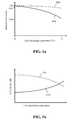
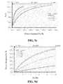
- the inventorshave appreciated that such a device has limitations. Most notably the Correlated Color Temperature (CCT) and CRI of light generated by such a device can vary significantly with operating temperature. As represented in FIG. 1 a the change in emission intensity of blue and red light emitting LEDs with operating temperature is different. Typically the emission intensity of a red LED decreases much more quickly than a blue LED with increased operating temperature. For example over an operating temperature range of 25° C. to 75° C. the emission intensity of a GaN-based blue LED can decrease by about 5% whilst the emission intensity of a AlGaInP-based red LED can decrease by about 40%.
- CCTCorrelated Color Temperature
- the present inventionarose in an endeavor to provide a white light emitting device with a high CRI, typically 80 or higher, that at least in part overcomes the limitations of the known devices.
- a white light emitting devicecomprises: at least one blue solid state light emitter operable to generate blue light with a dominant wavelength in a range 400 to 480 nm; at least one phosphor material operable to absorb a portion of the blue light and to emit light with a dominant wavelength in a range 490 to 590 nm; and at least one red solid state light emitter operable to generate red light with a dominant wavelength in a range 600 to 700 nm; wherein the emission product of the device comprises the combined light generated by the blue and red light emitters and light generated by the at least one phosphor material and appears white in color; and a drive circuit operable to compensate for variation in the ratio of red to blue light in the emission product such that over an operating temperature range of at least 25° C.
- the drive circuitis configured to maintain the ratio (relative contribution) of red and blue light in the emission product constant over the operating temperature range.
- the ratio of red to blue light in the emission productwill vary over the operating temperature range and the drive circuit is configured such that said variation is a low as possible preferably less than 10%, more preferably less than 5% and advantageously less than 1%.
- the operating temperature rangeis as large as possible and is at least 20° C., preferably at least 25° C., more preferably at least 50° C. and even more preferably at least 100° C.
- the deviceis configured such that the emission product has a minimum color rendering index of at least 80, preferably at least 85, more preferably at least 90 and ideally 95 or higher.
- the drive circuitis operable to control the power of at least one of the red and blue light emitters in response to a parameter related to the operating temperature of at least one of the blue and red light emitters.
- the drive circuitcan be operable to control the light emitter's drive current, drive voltage or a combination of both.
- the parametercomprises the temperature of at least one of the blue or red light emitters.
- the devicefurther comprises a sensor for sensing the temperature of at least the red and/or blue light emitters.
- the blue and red light emittersare mounted in thermal communication with a thermally conductive substrate and the sensor is configured to sense the temperature of the substrate.
- a respective sensorcan be provided for sensing the respective temperature of the blue and red light emitters.
- the temperature sensorcan comprise a temperature dependent resistor (thermistor), a thermocouple or other device having an electrical characteristic that is temperature dependent.
- a temperature dependent resistorthermocouple
- the sensorcomprises a temperature dependent resistor
- at least one of the blue and red light emitterscan be connected in series with the temperature dependent resistor and said light emitter operated from a constant voltage source. Since the electrical resistance of a solid state light emitter decreases with increasing temperature such a circuit configuration increases the forward drive current of one or both light emitters in response to an increase in operating temperature.
- the temperature dependent resistorhas a negative temperature coefficient and is connected in series with the at least one red light emitter.
- the temperature dependent resistorhas a positive temperature coefficient and is connected in series with the at least one blue light emitter.
- the blue and red light emittersare connected in series with a respective temperature dependent resistor.
- the temperature dependant resistor connected to the red light emitterhas negative temperature coefficient whilst the temperature dependant resistor connected to the blue light emitter has a positive temperature coefficient.
- each of the temperature dependent resistorscan have a negative temperature coefficient.
- the senorcomprises a temperature dependent resistor
- at least one of the blue and red emitterscan be connected in parallel with the temperature dependent resistor and said light emitter operated from a constant current source.
- Such circuit configurationsoperate as a current divider and alter the forward drive current of one or both light emitters in response to a change in operating temperature.
- the temperature dependent resistorhas a positive temperature coefficient and is connected in parallel with the at least one red light emitter.
- the temperature dependent resistorhas a negative temperature coefficient and is connected in parallel with the at least one blue light emitter.
- the blue and red light emitterare connected in parallel with a respective temperature dependent resistor.
- the temperature dependant resistor connected in parallel with the red light emitterhas positive temperature coefficient whilst the temperature dependant resistor connected in parallel with the blue light emitter has a negative temperature coefficient.
- each of the temperature dependent resistorscan have a positive temperature coefficient.
- the blue and red light emittersare connected in parallel and driven from a constant current source and the temperature dependent resistor has a negative temperature coefficient and is connected in series with the at least one red light emitter and configured such that in operation the drive current of the at least one red light emitter increases relative to the drive current of the at least one blue light emitter with increasing temperature.
- the blue and red light emittersare connected in parallel and driven from a constant current source and the temperature dependent resistor has a positive temperature coefficient and is connected in series with the at least one blue light emitter and configured such that in operation the drive current of the at least one blue light emitter decreases relative to the drive current of the at least one red light emitter with increasing temperature.
- the blue and red light emittersare connected in parallel and driven from a constant current source and a respective temperature dependent resistor is connected in series with the blue and red light emitters.
- the resistance and temperature coefficientare selected such the temperature dependent resistor has a resistance/temperature characteristic that is related to the emission intensity/temperature characteristic of at least one of the blue and red light emitters.
- the resistance and temperature coefficientare preferably selected such the temperature dependent resistor has a resistance/temperature characteristic that is related to the difference in emission intensity/temperature characteristic of the blue and red light emitters.
- the resistance and temperature coefficientare selected such the temperature dependent resistor has a resistance/temperature characteristic that is related to the emission intensity/temperature characteristic of a respective light emitter.
- the drive circuitis operable to compare the measured temperature with a reference temperature and in dependence on the difference in temperature, to control the drive current or drive voltage of one or both light emitters to maintain the relative contributions of red and blue light in the emission product substantially constant.
- the drive circuitis operable to control the drive current of the red light emitter(s).
- the drive circuitis operable to control the drive current of the blue light emitter(s).
- the drive circuitcomprises a voltage comparator operable to compare voltages corresponding to the measured and reference temperatures.
- the drive circuitis operable to control the drive current in dependence on the forward drive voltage of at least one of the blue and red light emitters.
- a benefit of using the forward drive voltage to control the drive currentis that it eliminates the need for a temperature sensor enabling the drive circuit to be located remotely to the device.
- the drive circuitis operable to control the drive current in dependence on the difference between the forward drive voltages of the blue and red light emitters.
- Such a configurationcan be implemented using a voltage comparator to compare the forward drive voltages of the blue and red emitters and to control the current of a controllable current source driving the blue and/or red light emitters.
- FIG. 1 ais a plot of emitted light intensity versus operating temperature for blue and red light emitting LEDs as previously described;
- FIG. 1 bis a plot of CCT and CRI of emitted light versus operating temperature for a known white light emitting device comprising blue and red LEDs as previously described;
- FIG. 2 ais a plan view of a white light emitting device in accordance with an embodiment of the invention.
- FIG. 2 bis a sectional view of the device of FIG. 2 a through A-A;
- FIG. 2 cis a sectional view of the device of FIG. 2 a through A-A showing an alternative phosphor configuration
- FIG. 2 dis a sectional view of the device of FIG. 2 a through A-A showing another alternative phosphor configuration
- FIG. 2 eis a sectional view of the device of FIG. 2 a through A-A with a remote phosphor configuration
- FIG. 3 ais a plan view of a white light emitting device in accordance with another embodiment of the invention.
- FIG. 3 bis a sectional view of the device of FIG. 3 a through A-A;
- FIG. 4 ais a plan view of a white light emitting device in accordance with a further embodiment of the invention.
- FIG. 4 bis a sectional view of the device of FIG. 4 a through A-A;
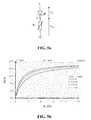
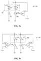
- FIG. 5 ais a circuit diagram of an LED connected in series with a temperature dependent resistor
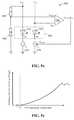
- FIG. 5 bis a plot of percentage change of forward drive current ( ⁇ i F /i F ) versus temperature dependent resistor resistance (R T ) for drive currents of 40 mA, 160 mA, 350 mA, 400 mA for the circuit of FIG. 5 a;
- FIG. 5 cis a plot of percentage change of forward drive current ⁇ i F /i F versus proportion of power dissipated by the temperature dependent resistor for drive currents of 40 mA, 160 mA, 350 mA, 400 mA for the circuit of FIG. 5 a;
- FIG. 5 dis a plot of the proportion of power dissipated by the temperature dependent resistor versus temperature dependent resistor resistance R T for drive currents of 40 mA, 160 mA, 350 mA, 400 mA for the circuit of FIG. 5 a;
- FIGS. 5 e to 5 jare constant voltage drive circuits for operating the devices of FIGS. 2 to 4 ;
- FIGS. 5 k to 5 pare constant current drive circuits for operating the devices of FIGS. 2 to 4 ;
- FIGS. 5 q and 5 rare controllable current drive circuits for operating the devices of FIGS. 2 to 4 ;
- FIG. 5 sis a schematic plot of normalized LED forward drive voltage V F versus operating temperature for blue and red light emitting LEDs
- FIGS. 5 t to 5 xare controllable current drive circuits for operating the devices of FIGS. 2 to 4 ;
- FIG. 5 yis a schematic plot of difference in LED forward drive voltage V FB ⁇ V FR versus operating temperature for blue and red light emitting LEDs.
- Embodiments of the inventionare directed to white light emitting devices comprising at least one blue solid state light emitting device that is operable to generate blue light with a dominant wavelength in a range 400 nm to 480 nm (blue); at least one phosphor material operable to absorb a portion of the blue light emitted by the blue light emitter(s) and to emit light with a dominant wavelength in a range 490 nm to 590 nm (bluish green to orange yellow); and at least one red solid state light emitter that is operable to generate red light with a dominant wavelength in a range 600 nm to 700 nm (red).
- the emission product of the devicewhich appears white in color, comprises the combined light generated by the blue and red light emitters and the light generated by the phosphor material.
- the deviceis configured to have a CRI of at least 80.
- the devicefurther comprises drive circuitry that is operable to control the power (forward drive current, forward drive voltage or a combination of both) of the red and/or blue light emitters in response to a parameter that is related to the operating temperature of the blue and/or red light emitters such as to maintain the relative contributions (ratio) of red and blue light in the emission product substantially constant.
- Such a devicecan produce an emission product whose CRI and CCT are substantially constant. Typically the variation in CRI and/or CCT is less than 10%.
- the parameter used to control the drive power of the light emitter(s)can comprise an operating temperature of the light emitter(s).
- the parametercan comprise the forward drive voltage which is related to the light emitter's operating temperature.
- the drive circuitrycan be incorporated in the device packaging or provided separately to the device, for example, as a part of power supply used to operate the device.
- FIGS. 2 a to 2 e , 3 a , 3 b , 4 a and 4 b of the accompanying drawingsExamples of light emitting devices in accordance with the invention will now be described with reference to FIGS. 2 a to 2 e , 3 a , 3 b , 4 a and 4 b of the accompanying drawings.
- like reference numerals preceded by the figure numberare used to denote like parts.
- a white light emitting device 200 in accordance with an embodiment of the inventionis now described with reference to FIGS. 2 a and 2 b which respectively show a schematic plan view of the device and a sectional view through A-A.
- the device 200is configured to generate white light with a Correlated Color Temperature (CCT) of ⁇ 2700K, a minimum emission luminous flux of ⁇ 750 lumens (lm), a minimum luminous efficacy of 100 lm/W and a minimum CRI of 80.
- CCTCorrelated Color Temperature
- the device 200comprises a package 202 ( FIG. 2 b ) such as for example is described in co-pending U.S. patent application Ser. No. 12/781,194 filed May 16, 2010 entitled “Light Emitting Device” (Hwa S U et al.) the entire content of which is incorporated herein by way of reference thereto.
- the package 202comprises a layered structure comprising in order a 1 cm square copper (Cu) substrate 204 , a circuit layer 206 and a square ceramic (Al 2 O 3 ) top 208 .
- the ceramic top 208includes a circular through hole such that when the top 208 is mounted to the copper substrate 204 it defines a shallow circular recess 210 .
- a blue (dominant wavelength in a range 450 nm-480 nm, typically about 465 nm) light emitting LED chip 212is mounted on the center of the floor of the recess 210 in direct thermal communication with the copper substrate 204 .
- the blue LED chip 212can comprise, for example, a GaN (gallium nitride) based monolithic LED chip array such as an MC (multi chip) chip manufactured by Epistar Corporation® of Taiwan.
- Such an LED multi chiptypically has a dominant emission wavelength of 450 nm, 460 nm or 470 nm and a radiant flux of 1500 mW to 2000 mW.
- the devicefurther comprises two red (600 nm-700 nm) light emitting LED chips 214 mounted adjacent the blue LED chip 212 on the floor of the recess 210 in direct thermal communication with the copper substrate 204 .
- the red LED chips 214can comprise, for example, an AlGaInP (aluminum gallium indium phosphide) based LED chips such as Epistar Corporation's® ES-LASOPH42 chip. Such LED chips typically have a dominant emission wavelength of 615 nm and an emission luminous flux of 35 lm to 45 lm.
- the LED chips 212 , 214are electrically connected to the circuit layer 206 by bond wires 216 .
- the circuit layer 206can comprise an arrangement of thin copper tracks on one or more thin electrically insulating layer(s) 207 and is configured to interconnect the LEDs in a desired circuit configuration.
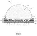
- the device 200further comprises a dome-shaped (generally hemispherical) lens 218 which has a uniform thickness layer of phosphor material 220 on its planar base.
- the phosphor or photoluminescent material 220is operable to absorb at least a portion of the blue light emitted by the LED chip 212 and to emit light with a dominant wavelength in a range 490 nm to 590 nm (bluish green to orange yellow).
- the devices of the inventionare particularly suited to use with inorganic phosphor materials such as for example silicate-based phosphor of a general composition A 3 Si(O,D) 5 or A 2 Si(O,D) 4 in which Si is silicon, O is oxygen, A comprises strontium (Sr), barium (Ba), magnesium (Mg) or calcium (Ca) and D comprises chlorine (Cl), fluorine (F), nitrogen (N) or sulfur (S).
- silicate-based phosphorsare disclosed in U.S. Pat. No. 7,575,697 “Europium activated silicate-based green phosphor” (assigned to Intematix Corp.), U.S. Pat. No.
- the phosphorcan also comprise an aluminate-based material such as is taught in our co-pending patent application US2006/0158090 “Aluminate-based green phosphor”, an aluminum-silicate phosphor as taught in co-pending application US2008/0111472 “Aluminum-silicate orange-red phosphor” or a nitride-based red phosphor material such as is taught in our co-pending U.S. patent application Ser. No. 12/632,550 filed Dec. 7, 2009.
- the phosphor materialis not limited to the examples described herein and can comprise any phosphor material including nitride and/or sulfate phosphor materials, oxy-nitrides and oxy-sulfate phosphors or garnet materials (YAG).
- the phosphor material 220which is in powder form, is thoroughly mixed in known proportions with a liquid binder material to form a suspension and the resulting phosphor composition deposited onto the surface of the lens 218 using for example spin coating, screen printing, inkjet, letterpress, gravure or flexograph printing.
- the liquid binder materialcan comprise a U.V. or thermally curable liquid polymer such as a U.V. curable acrylic adhesive or silicone.
- light emitted by the device 200which appears white in color, comprises the combined light emitted by the blue LED chip 212 , red LED chips 214 and green/yellow light generated by the phosphor material 220 .
- the phosphor material 220can be incorporated in the lens 218 which is fabricated from a light transmissive polymer material such as an optical grade silicone, acrylic, polycarbonate, poly(methyl methacrylate) (PMMA).
- a light transmissive polymer materialsuch as an optical grade silicone, acrylic, polycarbonate, poly(methyl methacrylate) (PMMA).
- PMMApoly(methyl methacrylate)
- the lens 218can comprise a dome-shaped (generally hemispherical) shell and the phosphor material phosphor material 220 can be deposited as one or more uniform thickness layers on the inner curved surface of the lens ( FIG. 2 d ).
- the phosphor material remote to the device 200in the form of an optical component such as, for example, a light transmissive window 221 that includes one or more layers of phosphor material 220 .
- the phosphor materialcan be incorporated in the light transmissive window 221 .
- the window 221 including the phosphor material 220is physically separated from the device 200 , by an air gap of length L that is typically at least 5 mm to provide adequate thermal isolation of the phosphor material. Locating the window remote to the device provides a number of benefits namely reduced thermal degradation of the phosphor material.
- the phosphor materialis provided in close or direct contact with the light emitting surface of the LEDs, providing the phosphor material remote to the device reduces absorption of backscattered light by the device. Furthermore locating the phosphor material remotely enables generation of light of a more consistent color and/or CCT since the phosphor material is provided over a much greater area as compared to providing the phosphor directly to the light emitting surface of the LED chip(s).
- the window 221is fabricated from a light transmissive polymer material such as an optical grade silicone, acrylic, polycarbonate, poly(methyl methacrylate) (PMMA) or a glass such as fused silica or a borosilicate glass such as Pyrex® (Pyrex® is a brand name of Corning Inc).
- a light transmissive polymer materialsuch as an optical grade silicone, acrylic, polycarbonate, poly(methyl methacrylate) (PMMA) or a glass such as fused silica or a borosilicate glass such as Pyrex® (Pyrex® is a brand name of Corning Inc).
- a light transmissive polymer materialsuch as an optical grade silicone, acrylic, polycarbonate, poly(methyl methacrylate) (PMMA) or a glass such as fused silica or a borosilicate glass such as Pyrex® (Pyrex® is a brand name of Corning Inc).
- Pyrex®is a brand name of Corning
- a white light emitting device 300 in accordance with another embodiment of the inventionis now described with reference to FIGS. 3 a and 3 b which respectively show a schematic plan view of the device and a sectional view through a line A-A.
- the device 300is configured to generate white light with a Correlated Color Temperature (CCT) of ⁇ 2700K, a minimum emission luminous flux of ⁇ 750 lm, a minimum luminous efficacy of 100 lm/W and a minimum CRI of 80.
- CCTCorrelated Color Temperature
- the device 300is virtually identical to the arrangement of FIGS. 2 a and 2 b except that it contains four lower power red (600 nm-700 nm) light emitting LED chips 314 .
- the LED chips 314are mounted around the blue LED chip array 312 on the floor of the recess 310 in direct thermal communication with the copper substrate 304 .
- the red LED chips 314can comprise, for example, an AlGaInP (aluminum gallium indium phosphide) based LED chips such as Epistar Corporation's® ES-LASOPH28 chip.
- Such LED chipstypically have a dominant emission wavelength of 615 nm and an emission luminous flux of 25 to 30 lm.
- the lens 318is formed (molded) in situ on the package 302 by filling the recess 310 with the phosphor/polymer mixture.
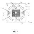
- a white light emitting device 400 in accordance with a third embodiment of the inventionis now described with reference to FIGS. 4 a and 4 b which respectively show a schematic plan view of the device and a sectional view through a line A-A.
- the device 400is configured to generate white light with a Correlated Color Temperature (CCT) of ⁇ 2700K, a minimum emission luminous flux of ⁇ 750 lm, a minimum luminous efficacy of 100 lm/W and a minimum CRI of 80.
- CCTCorrelated Color Temperature
- the device 400comprises an LTCC (low temperature co-fired ceramic) package 402 for example as described in co-pending United States patent application Publication No. US 2009/0294780 (filed May 27, 2008) the entire content of which is incorporated herein by way of reference thereto.
- the package 402is a square multilayered ceramic package having a square array of twenty five (five rows by five columns) circular recesses 410 .
- Each recess 410is configured to house a respective LED chip.
- the package 402comprises a 14 mm square ceramic body 408 containing one or more circuit layers 406 composed of silver (Ag).
- a silver mounting pad 422On the floor of each recess 410 there is provided a silver mounting pad 422 .
- the lower face of the packagecan include a thermally conductive base 424 .
- the mounting pads 422are connected in thermal communication with the base by thermally conductive vias 426 .
- Twenty blue (450 nm-480 nm) light emitting LED chips 412are mounted on the floor of a respective recess 410 in direct thermal communication with the silver mounting pad 422 .
- the blue LEDs 412can comprise, for example, InGaN (indium gallium nitride) based chips such as Epistar Corporation's® ES-CABLV24B H9 chip. Such an LED multi chip typically has a dominant emission wavelength of 450 nm, 460 nm or 470 nm and a radiant flux of 95 mW to 110 mW.
- InGaNindium gallium nitride
- the devicefurther comprises five red (600 nm-700 nm) light emitting LED chips 414 mounted within a respective recess 410 in direct thermal communication with the silver mounting pad 422 .
- the red LEDs 414can comprise, for example, an AlGaInP (aluminum gallium indium phosphide) based LED chip such as Epistar Corporation's® ES-LASOPH24. Such LED chips typically have a dominant emission wavelength of 615 nm and an emission luminous flux of 10 lm to 17 lm.
- the five red LED chips 414are located within the recesses 410 located at the center position of the array and each of the four corners of the square (three rows by three columns) surrounding the center recess.
- the LED chips 412 , 414are electrically connected by the circuit layer 406 .
- Each of the drive circuitsis operable to control the drive power of at least one of the red and/or blue LED chips in response to a parameter that is related to the operating temperature T of at least one of the red and/or blue LED chips such as to minimize variation in the ratio of red to blue light in the emission product of the device over the operating temperature range of the device.
- the drive circuitcan be housed within the device package or as incorporated as part of the power supply used to operate the device.
- the drive powercan be controlled by controlling the forward drive current i F , forward drive voltage V F or a combination of both of the red and/or blue LED chips.
- the parameter used to control the LED chip drive currentcan comprise the operating temperature of the red and/or blue LED chips or the forward drive voltage V F of the LED chip(s) which is related to the LED chip operating temperature.
- LEDscan be driven in a constant voltage or constant current configurations. Firstly drive circuits that are essentially constant voltage configurations are described.
- the forward drive current i F and/or drive voltage V F of the LEDcan be controlled to minimize the variation in the ratio of red to blue light in the emission product of the device over the device's operating temperature range.
- the temperature of one or both LED chipscan be used to control the forward drive current and/or voltage of the LED chips and the temperature is conveniently sensed using a temperature dependent resistor (thermistor).
- FIG. 5 ashows an LED connected in series with a temperature dependent resistor R T that is driven from a constant voltage source V.
- Vis the constant drive voltage
- V RTis the voltage drop across the temperature dependent resistor
- R Tis the resistance of the temperature dependent resistor.
- Tis the temperature and K the temperature coefficient of the temperature dependent resistor.
- the effective resistance of an LED(V F /i F ) is a non-linear function of temperature and decreases with increasing temperature.
- NTCnegative temperature coefficient
- the total resistanceR T +V F /i F
- the forward drive current i Fwill increase with increasing temperature.
- the forward drive current i F and forward drive voltage V F of the LEDwill change with temperature according to the relationship:
- ⁇ v F ⁇ i Fis the change of LED forward drive voltage with forward drive current.
- Values for ⁇ v F / ⁇ T and ⁇ v F / ⁇ i Fcan be empirically determined from the measured forward drive voltage V F versus temperature T and the forward drive voltage V F versus forward drive current i F characteristics of an LED driven from a constant voltage source (i.e. without the thermistor). As a result, the change in forward drive current i F at different temperatures can be calculated.
- FIG. 5 bare plots of the percentage change of forward drive current ( ⁇ i F /i F ) versus thermistor resistance R T over an operating temperature range 25° C. to 75° C.
- thermistorhas the capability of adjusting the forward current by a greater amount it will dissipate (consume) a greater proportion of the total power. For example at 25° C. approximately 65% of the total power will be dissipated by the thermistor for an LED driven with a forward drive current of 350 mA or 400 mA. As a result a balance has to be struck between these two effects (amount of current adjustment versus thermistor power consumption).
- the LED chipis under driven with a drive current of 40 mA using a 5 ⁇ (@25° C.) thermistor a maximum of 10% of the total power is dissipated by the thermistor and the current i F can be adjusted by up to 15%.
- a maximum of up to 15% of the total poweris consumed by the thermistor and i F can be adjusted by up to 13%.
- the thermistordissipated up to 15% of the total power and i F can be adjusted by up to 11%.
- the resistance of the thermistor and its temperature coefficientare selected according to the type of LED chip, the temperature characteristic of the LED chip and the interconnection of the LED chips (serial, parallel or a combination thereof).
- the value of R Tis selected such that the thermistor dissipates less than 15% of the total power but still offers a current adjustment (compensation) of >10%
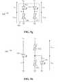
- FIG. 5 eis a first drive circuit 530 in which the red LED chips 514 of the device 500 are connected in series with an NTC thermistor 532 and operated from a constant voltage source V R whilst the blue LED chips 512 are driven directly from a constant voltage source V B .
- the resistance of the thermistor 532depends on temperature and is operable to control the forward drive current i FR of the red LED chips in dependence on the operating temperature of the red and/or blue LED chips.
- the thermistor 532can be mounted in the recess 210 , 310 of the package in thermal communication with the copper substrate 204 , 304 .
- the thermistor 532senses the temperature T of the substrate which is related to the operating temperature of the red and blue LED chips.
- the thermistor 532can be mounted in thermal communication with the silver mounting pad 422 corresponding to the blue or red LED chips or mounted in thermal communication with the thermally conductive base 424 .
- the intensity of light emitted by a red light emitting LEDtypically decreases much more quickly with an increase in operating temperature than the intensity of light emitted by a blue light emitting LED ( FIG. 1 a ).
- the thermistor 532has a negative temperature coefficient and the thermistor's resistance and temperature coefficient are selected to have a resistance/temperature characteristic that is related to the difference between the red and blue LED emission intensity/temperature characteristic.
- the resistance of the thermistor 532decreases resulting in an increase of forward drive current i FR of the red LED chip 514 .
- the change in the forward drive current i FRresults in an increase in emission intensity of the red LED chips.
- the circuit 530is configured to minimize any variation in the ratio of red to blue contributions in the emission product over the operating temperature range of the device and thereby reduce variation in the CCT and/or CRI of light emitted by the device. Ideally the circuit would be configured to maintain the relative contributions of red and blue light in the emission product constant over the operating temperature range.
- the circuitis configured to ensure that any variation in the relative contribution over the operating temperature range is less than a selected value, 20% or lower, preferably less than 10%, more preferably less than 5% and ideally 1% or lower. Since the circuit does not compensate for the decrease of emission intensity of the blue LED chips with increased temperature the overall emission intensity of the device will be lower at higher operating temperatures.
- a thermistor 536can be connected in series with the blue LED chip 512 and operated from a constant voltage source V B whilst the red LED chips driven from a constant voltage source V R .
- the thermistor 536is operable to measure the operating temperature of the red and/or blue LED chips.
- the thermistor 536preferably has a positive temperature coefficient (i.e. electrical resistance increases with increasing temperature) and the thermistor is selected to have a resistance/temperature characteristic that is related to the difference between the red and blue LED emission intensity/temperature characteristic.
- the resistance R T of the thermistor 536increases resulting in an increase in total resistance (R T +V F /i F ) and a decrease of forward drive current i FB of the blue LED chip 512 .
- the decrease of forward drive currentresults in a decrease in emission intensity of the blue LED chips.
- the circuit 534is configured such that over the operating temperature range of the device the variation in the ratio (relative contribution) of light emission from the red and blue LED chips is less than a selected value thereby reducing the variation in the CCT and/or CRI of light emitted by the device. It will be appreciated however that whilst any variation in CCT and/or CRI is minimized the overall emission intensity of the device will decrease with increased operating temperature as the circuit does not compensate for the decrease of emission intensity of the red LED chips.
- FIG. 5 gshows a drive circuit 538 in which a respective thermistor 532 , 536 is connected in series with the red and blue LED chips and used to independently control the forward drive current of the red and blue LED chips.
- the drive circuit 538is a combination of circuits 530 ( FIG. 5 e ) and 534 ( FIG. 5 f ).
- Each thermistor 532 , 536can be operable to sense the operating temperature of a respective LED chip group or operable to measure the operating temperature of the red and blue LED chips.
- the thermistor 532is a NTC device and the thermistor 536 is a PTC device.
- an increase of operating temperaturewill result in an increase of the forward drive current i FR of the red LED chip and a decrease of the forward drive current i FB of the blue LED chip.
- the net effect of the change of forward drive currentsreduces any change in the ratio of light emission from the red and blue LED chips and thereby reduces the variation in the CCT and/or CRI of light emitted by the device. Whilst the CCT and/or CRI remain substantially constant the overall emission intensity will decrease due to the decrease of light emission from the blue LED chip. As described above ( FIG.
- the circuitBy configuring the circuit to decrease the emission intensity of the blue LED chip and to increase the emission intensity of the red LED chip with increasing temperature enables the overall maximum change of drive current to be increased over a given operating temperature range.
- such a configurationmay be capable of an overall maximum change of drive about 30% to 40% over an operating temperature range of 25° C. to 75° C. thereby enabling the variation in the ratio of red to blue light to be minimized to a variation of approximately 7%.
- both thermistors 532 , 536can be NTC devices and are selected to have a resistance/temperature characteristic that is related to the respective LED emission/temperature characteristic. With such a configuration an increase of operating temperature will result in an increase of the forward drive current of both the red LED and blue LED chips. Although such a circuit arrangement can additionally reduce any change of emission intensity, the variation in the CRI and CCT can be greater over the same operating temperature range.
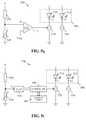
- FIG. 5 hshow a further drive circuit 540 in which the forward drive current i FR of the red LED chips 514 is controlled in dependence on the LED chip temperature and the blue LED chips 512 are driven from a constant voltage source.
- the red LED chip 514is connected in parallel with a PTC thermistor 542 of resistance R TP and the parallel combination connected in series with the NTC thermistor 532 of resistance R TS and operated from a constant voltage source V R .
- the blue LED chips 512are driven directly from a constant voltage source V B .
- the forward drive currentis given by the relationship:
- i FRV R - V FR R TS + V FR R TF
- the change of forward drive current i FR with temperatureis given by the relationship:
- the change (increase) in the forward drive current i FRresults in an increase in emission intensity of the red LED chip(s) 514 .
- the circuit 540is configured to ensure that the variation in the ratio (relative contribution) of light emission from the red and blue LED chips over the operating temperature range is within a selected range thereby reducing the variation in the CCT and/or CRI of light emitted by the device. Using two thermistors 532 , 542 enables a greater change of forward drive current for a given change of temperature.
- the forward drive current i FB of the blue LED chips 512is controlled in dependence on the LED chip temperature and the red LED chip 514 driven from a constant voltage source.
- the blue LED chip 512is connected in parallel with a NTC thermistor 546 (resistance R TP ) and the parallel combination connected in series with a PTC thermistor 536 (resistance R TS ) and operated from a constant voltage source V B .
- the red LED chips 514are driven directly from a constant voltage source V R .
- the circuit 544is configured to maintain the relative contribution of red and blue light in the emission product substantially constant over the operating temperature range of the device and thereby reduce any variation in the CCT and/or CRI of light emitted by the device. As with the circuit configuration 534 ( FIG. 5 f ) whilst the CCT and/or CRI remain substantially constant the overall emission intensity will drop with increasing temperature.
- FIG. 5 jshows a drive circuit 548 in which the forward drive currents i FR , i FB of the red and blue LED chips are independently controlled in dependence on LED chip temperature.
- the circuit 548is a combination of drive circuits 540 ( FIG. 5 h ) and 544 ( FIG. 5 i ) in which the red and blue LEDs chips are each connected in parallel with a respective thermistor 542 , 546 and the parallel combination then connected in series with a respective thermistor 532 , 536 .
- Each pair of thermistors 532 , 542 and 536 , 546can be operable to sense the operating temperature of a respective LED chip group or operable to measure the operating temperature of the red and blue LED chips.
- the thermistors 532 , 546can be NTC devices and the thermistor 536 , 542 can be PTC devices.
- an increase of operating temperaturewill result in an increase of the forward drive current i FR of the red LED chip and a decrease of the forward drive current i FB of the blue LED chip.
- the net effect of the change of forward drive currents i FR , i FBreduces variation in the ratio of light emission from the red and blue LED chips and thereby reduces the variation in the CCT and/or CRI of light emitted by the device. Whilst the CCT and/or CRI may remain substantially constant the overall emission intensity will decrease due to the decrease of light emission from the blue LED chip.
- the thermistorscan be selected to have a resistance/temperature characteristic that is related to the difference between the emission intensity/temperature characteristics of the red and blue LED chips.
- the thermistors 532 , 536can be NTC devices and the thermistors 542 , 546 can be PTC devices. With such a configuration an increase of operating temperature will result in an increase of the forward drive currents i FR , i FB of both the red and blue LED chips 514 , 512 .
- the thermistorscan be selected to have a resistance/temperature characteristic that is related to the respective LED emission intensity/temperature characteristic.
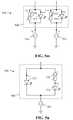
- FIGS. 5 k to 5 pshow various drive circuit configurations that are driven from a constant current source.
- the red LED chips 514are connected in parallel with a PTC (positive temperature coefficient) thermistor 532 and operated from a constant current source 552 I R whilst the blue LED chips 512 are driven directly from a constant current source 554 I B .
- the parallel thermistor/LED 532 / 514 configurationacts as a current divider such that in operation an increase in temperature causes the resistance of the thermistor to increase which results in a higher proportion of the current I R to flow through the arm including the red LED chip and an increase in the forward drive current I FR of the red LED chips.
- the forward drive voltage V FR of the red LED chipis constant the forward drive current is given by the relationship:
- i FRI R - V FR R T
- the change of forward drive current i FR with temperatureis given by the relationship:
- the thermistor 532has a resistance and temperature coefficient that are selected to have a resistance/temperature characteristic that is related to the difference between the red and blue LED emission intensity/temperature characteristics.
- the circuit 550is configured to minimize variation in the ratio (relative contribution) of red and blue light in the emission product over the operating temperature range and thereby reduce variation in the CCT and/or CRI of light emitted by the device.
- the blue LED chips 512are connected in parallel with a NTC thermistor 536 and operated from a constant current source 554 I B whilst the red LED chips 514 are driven directly from a constant current source 552 I R .
- an increase in temperaturecauses the resistance of the thermistor 536 to decrease which results in a lower proportion of the current I B to flow through the arm including the blue LED chips and a decrease in the forward drive current i FB of the blue LED chips.
- the decrease of forward drive currentresults in a decrease in emission intensity of the blue LED chips.
- the thermistor 532has a resistance and temperature coefficient that are selected to have a resistance/temperature characteristic that is related to the difference between the red and blue LED emission intensity/temperature characteristics.
- the circuit 556is configured to minimize variation in the ratio of red and blue light in the emission product over the operating temperature range of the device and thereby reduce the variation in the CCT and/or CRI of light emitted by the device. It will be appreciated that whilst the CCT and/or CRI remain substantially constant the overall emission intensity of the device will fall with increasing temperature due to the decrease in emission intensity of the blue LED chip.
- FIG. 5 mshows a drive circuit 558 in which a respective thermistor 532 , 536 is connected in parallel with the red and blue LED chips and used to independently control the forward drive current i FR , i FB of the red and blue LED chips.
- the drive circuit 558is a combination of circuits 550 ( FIG. 5 k ) and 556 ( FIG. 5 l )
- the thermistor 532is a PTC device and the thermistor 536 is a NTC device.
- both thermistors 532 , 536are PTC devices and are selected to have a resistance/temperature characteristic that is related to the respective LED emission intensity/temperature characteristic.
- FIG. 5 nis a drive circuit 560 in which the blue LED chips 512 and red LED chips 514 are connected in parallel and operated from a single constant current source 562 .
- a thermistor 532is connected in series in the arm of the circuit containing the red LED chips 514 and is operable to control the relative drive currents of the red and blue LED chips in dependence on the operating temperature of the red and/or blue LED chips.
- the thermistor 532has a negative temperature coefficient and is selected to have a resistance/temperature characteristic that is related to the difference between the red and blue LED chip emission intensity/temperature characteristics.
- the resistance of the thermistor 532decreases resulting in an increase of forward drive current i FR of the red LED chip 514 and a corresponding decrease of forward drive current i FB of the blue LED chip 512 .
- the relative change in the forward drive currentsresults in an increase in emission intensity of the red LED chips and a decrease in emission intensity of the blue LED chips.
- the circuit 560is configured to minimize variation in the relative contribution (ratio) of light emission from the red and blue LED chips and thereby reduce variation in the CCT and/or CRI of light emitted by the device 500 .
- the thermistor 536can be connected in the arm of the circuit containing the blue LED chip 512 .
- the thermistor 536is operable to measure the operating temperature of the red and/or blue LED chips.
- the thermistor 536has a positive temperature coefficient and is selected to have a resistance/temperature characteristic that is related to the difference between the red and blue LED emission/temperature characteristics.
- the resistance of the thermistor 536increases resulting in a decrease of forward drive current i FB of the blue LED chip 512 and a corresponding increase of forward drive current i FR of the red LED chip 514 .
- the change in the forward drive currentsresults in an increase in emission intensity of the red LED chips and a decrease in emission intensity of the blue LED chips.
- the circuit 564is configured to minimize variation in the relative contribution of red and blue light contributions in the emission product over the operating temperature range of the device and thereby reduce variation in the CCT and/or CRI of light emitted by the device.
- FIG. 5 pshows a drive circuit 566 in which respective thermistors 532 , 536 are used to control the forward current i FR , i FB of the red and blue LED chips 514 , 512 .
- Each thermistor 532 , 536can be operable to sense the operating temperature of a respective LED chip group or operable to measure the operating temperature of the red and blue LED chips.
- the thermistor 532is a NTC device and the thermistor 536 is a PTC device.
- both thermistors 532 , 536are NTC devices and are selected to have a resistance/temperature characteristic that is related to the respective LED emission intensity/temperature characteristic.
- FIGS. 5 q , 5 r and 5 t to 5 xshow various drive circuits based on a controllable current source(s).
- FIG. 5 qshows a drive circuit 568 in which the blue LED chips 512 are driven directly from a constant current source 554 and the red LED chips 514 are driven from a controllable current source 570 whose current is controllable to compensate for changes in the LED chip operating temperature.
- a thermistor 536is connected in series with one or more resistors 572 to form a potential divider arrangement such as to produce a voltage V T that is related to the temperature T of the thermistor 536 . As illustrated in FIG.
- the thermistor 536is connected to ground and is a PTC device such that the voltage V T will increase with increasing temperature.
- the voltage V Tis compared with a reference voltage V TREF using a voltage comparator 574 or like device.
- the reference voltage V TREFis selected to be representative of the normal operating temperature of the LED chips.
- the comparator 574produces an output voltage V CTRL that is related to the difference between the voltages V T and V TREF and hence related to the difference between the actual and normal operating temperatures.
- the control voltage V CTRLis used to control the controllable current source 570 and the forward drive current i FR of the red LED chips 514 .
- the variation with temperature in emission intensity of the red LED chips 514will be greater than that of the blue LED chips 512 it is only necessary to control the forward drive current of the red LED chips to minimize the variation in CCT and/or CRI of the device. It is however contemplated in other circuit configurations to alternatively control the forward drive current i FB of the blue LED chips or to independently control the forward drive current of the red and blue LED chips. In the case of the latter the thermistors 532 , 536 can be configured to measure the temperature of a respective color of LED chip or to measure the temperature of the red and blue LED chips.
- the voltage V T corresponding to the operating temperature of the LED chip(s)can be converted into a digital value using an A to D (Analogue to Digital) converter 578 and the digital value used by a controller 580 to control a controllable current source 570 .
- the circuit 576can further comprise a look-up table 582 that the controller 580 accesses to determine the appropriate forward drive current to minimize the variation in the CCT and/or CRI of light emitted by the device 500 . Since the configuration uses a look-up table containing values that can take account of the non-linear nature of the LED emission intensity/temperature characteristic the drive circuit 576 offers potentially very accurate control of the emission product of the device.
- the forward drive voltage V Fis related to the operating temperature of the LED ( FIG. 5 s ) and the inventors have appreciated that the LED forward drive voltage V F can be used as an indicator of LED operating temperature to control operation of the LED.
- the circuit configurations 584 , 586 , 592 , 594 and 598 of FIGS. 5 t to 5 xoperate in such a manner and eliminate the need to measure the LED chip temperature.
- a further advantage of using the forward drive voltage as an indicator of LED temperatureis that all of the control circuitry can be located remote from the light emitting device.
- the blue LED chips 512are driven from a constant current source 554 and the red LED chips 514 are driven from a controllable current source 570 whose current is controllable in dependence on the forward drive voltage V FR of the red LED chips to compensate for changes in the LED chip operating temperature.
- the forward drive voltage V FRis compared with a reference voltage V VREFR using a voltage comparator 574 or like device.
- the reference voltage V VREFRis selected to be representative of the forward drive voltage at the normal operating temperature of the LED chip.
- the comparator 574produces an output voltage V CTRL that is related to the difference between the voltages V FR and V VREFR and hence related to the difference between the actual and normal operating temperatures.
- the control voltage V CTRLis used to control the controllable current source 570 and the forward drive current i FR of the red LED chips 514 .
- FIG. 5 ushows a drive circuit 586 in which the red LED chips 514 are driven from a constant current source 552 and the blue LED chips 512 are driven from a controllable current source 588 whose current is controllable in dependence on the forward drive voltage V FB of the blue LED chips to compensate for changes in the LED chip operating temperature.
- the forward drive voltage V FBis compared with a reference voltage V VREFB using a voltage comparator 590 or like device.
- the reference voltage V VREFBis selected to be representative of the forward drive voltage at the normal operating temperature of the LED chip.
- the comparator 590produces an output voltage V CTRL that is related to the difference between the voltages V FB and V VREFB and hence related to the difference between the actual and normal operating temperatures.
- the control voltage V CTRLis used to control the controllable current source 588 and the forward drive current i FB of the blue LED chips 512 .
- FIG. 5 vshows a drive circuit 592 in which the red and blue LED chips 512 , 514 are driven by a respective controllable current source 570 , 588 whose current is controllable in dependence on the forward drive voltage V FR , V FB of the red and blue LED chip(s) to compensate for changes in the LED chip operating temperature.
- the drive circuit 592is a combination of drive circuits 584 ( FIG. 5 t ) and 586 ( FIG. 5 u ) and operates in a like manner.
- FIG. 5 wshows a drive circuit 594 in which the blue LED chips 512 are driven from a constant current source 554 and the red LED chips 514 are driven from a controllable current source 570 whose current is controllable in dependence on a difference in forward drive voltage V FB ⁇ V FR of the LED chip(s) 512 , 514 to compensate for changes in the LED chip operating temperature.
- FIG. 5 xis a drive circuit 598 that is similar to the drive circuit 594 except that it is configured such that the forward drive voltages V FB and V FR used to control the current source are normalized such that they are equal at the normal operating temperature T n of the device.
- a potential divider arrangementcomprising resistors R 1 600 and R 2 602 is configured such that at the normal operating temperature T n the normalized forward drive voltage for the blue LED chips V FBN is equal to the forward drive voltage of the red LED chips V FR and is given by the relation:
- FIG. 5 yis a schematic plot of the control voltage V FBN ⁇ V FR versus LED operating temperature.
- the control voltage V CTRLis used to control the controllable current source 570 and the forward drive current i FR of the red LED chips to thereby maintain the relative contribution of light emission from the red and blue LED chips substantially constant thereby reducing the variation in the CCT and/or CRI of light emitted by the device 500 .
- the light emitting device 500is indicated by a dashed line box and comprises at least one blue LED chip 512 and at least one red LED chip 514 . It is envisaged that the light emitting device of the invention incorporate part or all of the drive circuitry described. Moreover it will be appreciated that the foregoing drive circuits are exemplary only and that other circuit configurations embodying the invention will be apparent to those skilled in the art.
- devices in accordance with the inventioncan comprise other LEDs such as silicon carbide (SiC), zinc selenide (ZnSe), indium gallium nitride (InGaN), aluminum nitride (AlN) or aluminum gallium nitride (AlGaN) based LED chips that emit blue or U.V. light.
- SiCsilicon carbide
- ZnSezinc selenide
- InGaNindium gallium nitride
- AlNaluminum nitride
- AlGaNaluminum gallium nitride
- the phosphor materialin the form of one or more layers on a surface of the lens, typically the planar face.
- the phosphor materialwhich is typically in powder form, is mixed with a binder material such as NAZDAR's clear screen ink 9700 and the mixture screen printed on the surface of the lens to form a layer of uniform thickness.
- a binder materialsuch as NAZDAR's clear screen ink 9700
- the phosphorcan be applied by other deposition methods such as spraying, ink jet printing or by mixing the powdered phosphor with a light transmissive binder material such as an epoxy or silicone and applying the phosphor/polymer mixture by doctor blading, spin coating etc.
- the lensis preferably mounted with the phosphor layer(s) facing the recess.
- the weight loading of phosphor material to light transmissive binder in the deposited materialis between 10% and 30% though it can range between 1% and 99% depending on the desired emission product and the package design.
- To deposit a sufficient density of phosphor material per unit area, for example 0.02-0.04 g/cm 2it may be necessary to make multiple print passes, the number of passes depending on the mesh size of the printing screen.
Landscapes
- Led Device Packages (AREA)
Abstract
Description
VF=V−VRT=V−iFRT
RT=R0(1+K(T−T0))
is the change of forward drive voltage with temperature and
is the change of LED forward drive voltage with forward drive current. Values for ∂vF/∂T and ∂vF/∂iFcan be empirically determined from the measured forward drive voltage VFversus temperature T and the forward drive voltage VFversus forward drive current iFcharacteristics of an LED driven from a constant voltage source (i.e. without the thermistor). As a result, the change in forward drive current iFat different temperatures can be calculated.
RTS<<VFR/iFR<<RTP,
R0S/RTS≈R0P/RTP, and
then the equation can be simplified to:
Claims (29)
Priority Applications (7)
| Application Number | Priority Date | Filing Date | Title |
|---|---|---|---|
| US12/945,641US8779685B2 (en) | 2009-11-19 | 2010-11-12 | High CRI white light emitting devices and drive circuitry |
| EP10832063AEP2502287A1 (en) | 2009-11-19 | 2010-11-16 | High cri white light emitting device and drive circuitry |
| PCT/US2010/056893WO2011062915A1 (en) | 2009-11-19 | 2010-11-16 | High cri white light emitting device and drive circuitry |
| JP2012539976AJP2013511846A (en) | 2009-11-19 | 2010-11-16 | High CRI white light emitting device and drive circuit |
| KR1020127015725AKR20120101682A (en) | 2009-11-19 | 2010-11-16 | High cri white light emitting devices and drive circuitry |
| CN2010800587909ACN102668134A (en) | 2009-11-19 | 2010-11-16 | High cri white light emitting device and drive circuitry |
| TW099140116ATWI556404B (en) | 2009-11-19 | 2010-11-19 | High color rendering index white light emitting device and driving circuit |
Applications Claiming Priority (2)
| Application Number | Priority Date | Filing Date | Title |
|---|---|---|---|
| US26285509P | 2009-11-19 | 2009-11-19 | |
| US12/945,641US8779685B2 (en) | 2009-11-19 | 2010-11-12 | High CRI white light emitting devices and drive circuitry |
Publications (2)
| Publication Number | Publication Date |
|---|---|
| US20110115406A1 US20110115406A1 (en) | 2011-05-19 |
| US8779685B2true US8779685B2 (en) | 2014-07-15 |
Family
ID=44010807
Family Applications (1)
| Application Number | Title | Priority Date | Filing Date |
|---|---|---|---|
| US12/945,641Expired - Fee RelatedUS8779685B2 (en) | 2009-11-19 | 2010-11-12 | High CRI white light emitting devices and drive circuitry |
Country Status (7)
| Country | Link |
|---|---|
| US (1) | US8779685B2 (en) |
| EP (1) | EP2502287A1 (en) |
| JP (1) | JP2013511846A (en) |
| KR (1) | KR20120101682A (en) |
| CN (1) | CN102668134A (en) |
| TW (1) | TWI556404B (en) |
| WO (1) | WO2011062915A1 (en) |
Cited By (6)
| Publication number | Priority date | Publication date | Assignee | Title |
|---|---|---|---|---|
| US20130241416A1 (en)* | 2010-09-29 | 2013-09-19 | European Intelligence B.V. | Intrinsically Safe Display Device with an Array of LEDS |
| US20140021884A1 (en)* | 2012-07-18 | 2014-01-23 | Dialight Corporation | High ambient temperature led luminaire with thermal compensation circuitry |
| US20140306605A1 (en)* | 2013-04-12 | 2014-10-16 | Polytronics Technology Corp. | Ptc composition and resistive device and led illumination apparatus using the same |
| US9013108B1 (en)* | 2013-12-11 | 2015-04-21 | Anwell Semiconductor Corp. | LED element with color light enhancement function |
| US10281128B2 (en) | 2015-05-19 | 2019-05-07 | Signify Holding B.V. | Lighting device comprising a split lighting engine |
| US20210315075A1 (en)* | 2020-04-02 | 2021-10-07 | Toshiba Lighting & Technology Corporation | Vehicle Luminaire and Vehicle Lighting Tool |
Families Citing this family (25)
| Publication number | Priority date | Publication date | Assignee | Title |
|---|---|---|---|---|
| DE102010002332A1 (en)* | 2009-11-30 | 2011-06-01 | Ledon Lighting Jennersdorf Gmbh | Retrofit LED lamp with warm white, especially flame-like white light |
| DE102010013493A1 (en)* | 2010-03-31 | 2011-10-06 | Osram Opto Semiconductors Gmbh | Optoelectronic device |
| CN102256408B (en)* | 2010-05-19 | 2014-01-08 | 光宝电子(广州)有限公司 | Control circuit of light emitting diode and light emitting diode apparatus |
| CN102458019B (en)* | 2010-10-26 | 2014-01-22 | 财团法人工业技术研究院 | Light color modulation method and light emitting diode light source module |
| DE102011002439A1 (en)* | 2011-01-04 | 2012-07-05 | Zumtobel Lighting Gmbh | LED module for passive luminous flux stabilization |
| WO2012164440A1 (en)* | 2011-06-01 | 2012-12-06 | Koninklijke Philips Electronics N.V. | A led-based illumination device with low heat up color shift |
| CN102387624B (en)* | 2011-09-02 | 2013-10-16 | 天津工业大学 | Warm white light LED lamp with mixed three primary colors |
| DE102011114253A1 (en)* | 2011-09-26 | 2013-03-28 | e:lumix OptoSemi Industries Verwaltungs GmbH | Lighting device e.g. street light comprises resistive element with positive temperature characteristic that is electrically connected with semiconductor element in series through thermal coupling and electrical connection |
| WO2013152234A1 (en)* | 2012-04-04 | 2013-10-10 | Axlen, Inc. | Optically efficient solid-state lighting device packaging |
| TWI456143B (en)* | 2012-04-26 | 2014-10-11 | 新世紀光電股份有限公司 | Light source module |
| CN104335367A (en)* | 2012-05-21 | 2015-02-04 | 株式会社Del | Light emitting device comprising chip-on-board package substrate and method for manufacturing same |
| EP2878173B8 (en)* | 2012-07-27 | 2019-04-10 | Signify Holding B.V. | Color emphasis and preservation of objects using reflection spectra |
| JP6396431B2 (en)* | 2013-05-03 | 2018-09-26 | フィリップス ライティング ホールディング ビー ヴィ | LED lighting circuit |
| JP6176525B2 (en)* | 2013-07-19 | 2017-08-09 | パナソニックIpマネジメント株式会社 | Light emitting module, lighting device and lighting fixture |
| KR102081600B1 (en)* | 2013-10-10 | 2020-02-26 | 엘지디스플레이 주식회사 | Liquid crystal display device |
| JP2015103666A (en)* | 2013-11-25 | 2015-06-04 | セイコーエプソン株式会社 | Light emitting device and image display device |
| US20150316219A1 (en)* | 2014-05-01 | 2015-11-05 | CoreLed Systems, LLC | High-pass filter for led lighting |
| CN104373838B (en)* | 2014-06-30 | 2016-03-23 | 深圳大学 | A kind of LED light source module and LED lamp |
| CN104376816A (en)* | 2014-11-21 | 2015-02-25 | 京东方科技集团股份有限公司 | LED backlight drive circuit, LED backlight device and display device |
| KR102408618B1 (en)* | 2015-02-16 | 2022-06-14 | 쑤저우 레킨 세미컨덕터 컴퍼니 리미티드 | Light emitting device package and lighting apparatus including the same |
| US10066160B2 (en) | 2015-05-01 | 2018-09-04 | Intematix Corporation | Solid-state white light generating lighting arrangements including photoluminescence wavelength conversion components |
| DE102015112048A1 (en) | 2015-07-23 | 2017-01-26 | Osram Oled Gmbh | Optoelectronic component and method for operating an optoelectronic component |
| US9560714B1 (en)* | 2016-02-25 | 2017-01-31 | Morten Hjerde | Color temperature adjustable, LED based, white light source |
| JP6722909B2 (en) | 2016-08-30 | 2020-07-15 | パナソニックIpマネジメント株式会社 | Color conversion element and lighting device |
| JP7064129B2 (en) | 2017-12-22 | 2022-05-10 | 日亜化学工業株式会社 | Light emitting device |
Citations (144)
| Publication number | Priority date | Publication date | Assignee | Title |
|---|---|---|---|---|
| US3290255A (en) | 1963-09-30 | 1966-12-06 | Gen Electric | White electroluminescent phosphor |
| US3593055A (en) | 1969-04-16 | 1971-07-13 | Bell Telephone Labor Inc | Electro-luminescent device |
| US3670193A (en) | 1970-05-14 | 1972-06-13 | Duro Test Corp | Electric lamps producing energy in the visible and ultra-violet ranges |
| US3676668A (en) | 1969-12-29 | 1972-07-11 | Gen Electric | Solid state lamp assembly |
| US3691482A (en) | 1970-01-19 | 1972-09-12 | Bell Telephone Labor Inc | Display system |
| US3709685A (en) | 1970-02-19 | 1973-01-09 | Ilford Ltd | Photoconductive zinc oxide sensitized by substituted thiazolidene dyes |
| US3743833A (en) | 1971-07-16 | 1973-07-03 | Eastman Kodak Co | Radiographic elements and binders |
| US3763405A (en) | 1970-12-21 | 1973-10-02 | Nippon Electric Co | Solid state luminescent display device |
| US3793046A (en) | 1970-12-04 | 1974-02-19 | Philips Corp | Method of manufacturing a pigment |
| US3819973A (en) | 1972-11-02 | 1974-06-25 | A Hosford | Electroluminescent filament |
| US3819974A (en) | 1973-03-12 | 1974-06-25 | D Stevenson | Gallium nitride metal-semiconductor junction light emitting diode |
| US3849707A (en) | 1973-03-07 | 1974-11-19 | Ibm | PLANAR GaN ELECTROLUMINESCENT DEVICE |
| US3875456A (en) | 1972-04-04 | 1975-04-01 | Hitachi Ltd | Multi-color semiconductor lamp |
| JPS5079379U (en) | 1973-11-24 | 1975-07-09 | ||
| US3932881A (en) | 1972-09-05 | 1976-01-13 | Nippon Electric Co., Inc. | Electroluminescent device including dichroic and infrared reflecting components |
| US3937998A (en) | 1973-10-05 | 1976-02-10 | U.S. Philips Corporation | Luminescent coating for low-pressure mercury vapour discharge lamp |
| US3972717A (en) | 1973-03-21 | 1976-08-03 | Hoechst Aktiengesellschaft | Electrophotographic recording material |
| US4047075A (en) | 1975-03-01 | 1977-09-06 | Licentia-Patent-Verwaltungs-G.M.B.H. | Encapsulated light-emitting diode structure and array thereof |
| US4075532A (en) | 1976-06-14 | 1978-02-21 | General Electric Company | Cool-white fluorescent lamp with phosphor having modified spectral energy distribution to improve luminosity thereof |
| US4081764A (en) | 1972-10-12 | 1978-03-28 | Minnesota Mining And Manufacturing Company | Zinc oxide light emitting diode |
| US4104076A (en) | 1970-03-17 | 1978-08-01 | Saint-Gobain Industries | Manufacture of novel grey and bronze glasses |
| US4143394A (en) | 1976-07-30 | 1979-03-06 | Licentia Patent-Verwaltungs-G.M.B.H. | Semiconductor luminescence device with housing |
| GB2017409A (en) | 1978-03-22 | 1979-10-03 | Bayraktaroglu B | Light-emitting diode |
| US4176299A (en) | 1975-10-03 | 1979-11-27 | Westinghouse Electric Corp. | Method for efficiently generating white light with good color rendition of illuminated objects |
| US4176294A (en) | 1975-10-03 | 1979-11-27 | Westinghouse Electric Corp. | Method and device for efficiently generating white light with good rendition of illuminated objects |
| US4211955A (en) | 1978-03-02 | 1980-07-08 | Ray Stephen W | Solid state lamp |
| US4305019A (en) | 1979-12-31 | 1981-12-08 | Westinghouse Electric Corp. | Warm-white fluorescent lamp having good efficacy and color rendering and using special phosphor blend as separate undercoat |
| US4315192A (en) | 1979-12-31 | 1982-02-09 | Westinghouse Electric Corp. | Fluorescent lamp using high performance phosphor blend which is protected from color shifts by a very thin overcoat of stable phosphor of similar chromaticity |
| US4443532A (en) | 1981-07-29 | 1984-04-17 | Bell Telephone Laboratories, Incorporated | Induced crystallographic modification of aromatic compounds |
| US4559470A (en) | 1981-04-22 | 1985-12-17 | Mitsubishi Denki Kabushiki Kaisha | Fluorescent discharge lamp |
| US4573766A (en) | 1983-12-19 | 1986-03-04 | Cordis Corporation | LED Staggered back lighting panel for LCD module |
| US4618555A (en) | 1984-01-11 | 1986-10-21 | Mitsubishi Chemical Ind., Ltd. | Electrophotographic photoreceptor comprising azo compounds |
| US4638214A (en) | 1985-03-25 | 1987-01-20 | General Electric Company | Fluorescent lamp containing aluminate phosphor |
| US4667036A (en) | 1983-08-27 | 1987-05-19 | Basf Aktiengesellschaft | Concentration of light over a particular area, and novel perylene-3,4,9,10-tetracarboxylic acid diimides |
| US4678285A (en) | 1984-01-13 | 1987-07-07 | Ricoh Company, Ltd. | Liquid crystal color display device |
| US4727003A (en) | 1985-09-30 | 1988-02-23 | Ricoh Company, Ltd. | Electroluminescence device |
| US4772885A (en) | 1984-11-22 | 1988-09-20 | Ricoh Company, Ltd. | Liquid crystal color display device |
| US4845223A (en) | 1985-12-19 | 1989-07-04 | Basf Aktiengesellschaft | Fluorescent aryloxy-substituted perylene-3,4,9,10-tetracarboxylic acid diimides |
| JPH01179471A (en) | 1988-01-07 | 1989-07-17 | Natl Inst For Res In Inorg Mater | Cubic boron nitride P-n junction light emitting device |
| US4859539A (en) | 1987-03-23 | 1989-08-22 | Eastman Kodak Company | Optically brightened polyolefin coated paper support |
| US4915478A (en) | 1988-10-05 | 1990-04-10 | The United States Of America As Represented By The Secretary Of The Navy | Low power liquid crystal display backlight |
| US4918497A (en) | 1988-12-14 | 1990-04-17 | Cree Research, Inc. | Blue light emitting diode formed in silicon carbide |
| JPH0291980U (en) | 1988-12-29 | 1990-07-20 | ||
| US4946621A (en) | 1986-04-29 | 1990-08-07 | Centre National De La Recherche Scientifique (Cnrs) | Luminescent mixed borates based on rare earths |
| US4992704A (en) | 1989-04-17 | 1991-02-12 | Basic Electronics, Inc. | Variable color light emitting diode |
| US5077161A (en) | 1990-05-31 | 1991-12-31 | Xerox Corporation | Imaging members with bichromophoric bisazo perylene photoconductive materials |
| US5110931A (en) | 1987-11-27 | 1992-05-05 | Hoechst Aktiengesellschaft | Process for the preparation of n,n'-dimethylperylene-3,4,9,10-tetracarboxylic diimide in high-hiding pigment form |
| US5126214A (en) | 1989-03-15 | 1992-06-30 | Idemitsu Kosan Co., Ltd. | Electroluminescent element |
| US5131916A (en) | 1990-03-01 | 1992-07-21 | Bayer Aktiengesellschaft | Colored fluorescent polymer emulsions for marker pens: graft copolymers and fluorescent dyes in aqueous phase |
| US5143438A (en) | 1990-10-15 | 1992-09-01 | Thorn Emi Plc | Light sources |
| US5143433A (en) | 1991-11-01 | 1992-09-01 | Litton Systems Canada Limited | Night vision backlighting system for liquid crystal displays |
| US5166761A (en) | 1991-04-01 | 1992-11-24 | Midwest Research Institute | Tunnel junction multiple wavelength light-emitting diodes |
| US5208462A (en) | 1991-12-19 | 1993-05-04 | Allied-Signal Inc. | Wide bandwidth solid state optical source |
| US5210051A (en) | 1990-03-27 | 1993-05-11 | Cree Research, Inc. | High efficiency light emitting diodes from bipolar gallium nitride |
| US5211467A (en) | 1992-01-07 | 1993-05-18 | Rockwell International Corporation | Fluorescent lighting system |
| US5237182A (en) | 1990-11-29 | 1993-08-17 | Sharp Kabushiki Kaisha | Electroluminescent device of compound semiconductor with buffer layer |
| US5264034A (en) | 1989-08-11 | 1993-11-23 | Hoechst Aktiengesellschaft | Pigment preparations based on perylene compounds |
| US5283425A (en) | 1992-02-06 | 1994-02-01 | Rohm Co., Ltd. | Light emitting element array substrate with reflecting means |
| US5369289A (en) | 1991-10-30 | 1994-11-29 | Toyoda Gosei Co. Ltd. | Gallium nitride-based compound semiconductor light-emitting device and method for making the same |
| US5405709A (en) | 1993-09-13 | 1995-04-11 | Eastman Kodak Company | White light emitting internal junction organic electroluminescent device |
| JPH07176794A (en) | 1993-12-17 | 1995-07-14 | Nichia Chem Ind Ltd | Surface light source |
| US5439971A (en) | 1991-11-12 | 1995-08-08 | Eastman Chemical Company | Fluorescent pigment concentrates |
| JPH087614Y2 (en) | 1990-05-08 | 1996-03-04 | 中部電力株式会社 | Wire cap |
| US5518808A (en) | 1992-12-18 | 1996-05-21 | E. I. Du Pont De Nemours And Company | Luminescent materials prepared by coating luminescent compositions onto substrate particles |
| US5535230A (en) | 1994-04-06 | 1996-07-09 | Shogo Tzuzuki | Illuminating light source device using semiconductor laser element |
| US5557168A (en) | 1993-04-02 | 1996-09-17 | Okaya Electric Industries Co., Ltd. | Gas-discharging type display device and a method of manufacturing |
| US5563621A (en) | 1991-11-18 | 1996-10-08 | Black Box Vision Limited | Display apparatus |
| US5578839A (en) | 1992-11-20 | 1996-11-26 | Nichia Chemical Industries, Ltd. | Light-emitting gallium nitride-based compound semiconductor device |
| US5583349A (en) | 1995-11-02 | 1996-12-10 | Motorola | Full color light emitting diode display |
| US5585640A (en) | 1995-01-11 | 1996-12-17 | Huston; Alan L. | Glass matrix doped with activated luminescent nanocrystalline particles |
| US5619356A (en) | 1993-09-16 | 1997-04-08 | Sharp Kabushiki Kaisha | Reflective liquid crystal display device having a compensator with a retardation value between 0.15 μm and 0.38 μm and a single polarizer |
| US5660461A (en) | 1994-12-08 | 1997-08-26 | Quantum Devices, Inc. | Arrays of optoelectronic devices and method of making same |
| US5677417A (en) | 1993-05-04 | 1997-10-14 | Max-Planck-Gesellschaft Zur Foerderung | Tetraaroxyperylene-3,4,9,10-tetracarboxylic polyimides |
| US5679152A (en) | 1994-01-27 | 1997-10-21 | Advanced Technology Materials, Inc. | Method of making a single crystals Ga*N article |
| US5763901A (en) | 1992-12-17 | 1998-06-09 | Kabushiki Kaisha Toshiba | Semiconductor light-emitting device and method for manufacturing the device |
| US5770887A (en) | 1993-10-08 | 1998-06-23 | Mitsubishi Cable Industries, Ltd. | GaN single crystal |
| US5771039A (en) | 1994-06-06 | 1998-06-23 | Ditzik; Richard J. | Direct view display device integration techniques |
| US5777350A (en) | 1994-12-02 | 1998-07-07 | Nichia Chemical Industries, Ltd. | Nitride semiconductor light-emitting device |
| US5869199A (en) | 1993-03-26 | 1999-02-09 | Sumitomo Electric Industries, Ltd. | Organic electroluminescent elements comprising triazoles |
| JP2900928B2 (en) | 1997-10-20 | 1999-06-02 | 日亜化学工業株式会社 | Light emitting diode |
| US5959316A (en) | 1998-09-01 | 1999-09-28 | Hewlett-Packard Company | Multiple encapsulation of phosphor-LED devices |
| US5962971A (en) | 1997-08-29 | 1999-10-05 | Chen; Hsing | LED structure with ultraviolet-light emission chip and multilayered resins to generate various colored lights |
| US5998925A (en) | 1996-07-29 | 1999-12-07 | Nichia Kagaku Kogyo Kabushiki Kaisha | Light emitting device having a nitride compound semiconductor and a phosphor containing a garnet fluorescent material |
| US6137217A (en) | 1992-08-28 | 2000-10-24 | Gte Products Corporation | Fluorescent lamp with improved phosphor blend |
| US6161910A (en) | 1999-12-14 | 2000-12-19 | Aerospace Lighting Corporation | LED reading light |
| US6340824B1 (en) | 1997-09-01 | 2002-01-22 | Kabushiki Kaisha Toshiba | Semiconductor light emitting device including a fluorescent material |
| US6441558B1 (en) | 2000-12-07 | 2002-08-27 | Koninklijke Philips Electronics N.V. | White LED luminary light control system |
| US20020130786A1 (en) | 2001-01-16 | 2002-09-19 | Visteon Global Technologies,Inc. | Series led backlight control circuit |
| US6504301B1 (en) | 1999-09-03 | 2003-01-07 | Lumileds Lighting, U.S., Llc | Non-incandescent lightbulb package using light emitting diodes |
| US6513949B1 (en) | 1999-12-02 | 2003-02-04 | Koninklijke Philips Electronics N.V. | LED/phosphor-LED hybrid lighting systems |
| US20030076056A1 (en) | 2001-10-22 | 2003-04-24 | Lumileds Usa | Method and apparatus for sensing the color point of an RGB LED white luminary using photodiodes |
| US6576488B2 (en) | 2001-06-11 | 2003-06-10 | Lumileds Lighting U.S., Llc | Using electrophoresis to produce a conformally coated phosphor-converted light emitting semiconductor |
| US6577073B2 (en) | 2000-05-31 | 2003-06-10 | Matsushita Electric Industrial Co., Ltd. | Led lamp |
| US6600175B1 (en) | 1996-03-26 | 2003-07-29 | Advanced Technology Materials, Inc. | Solid state white light emitter and display using same |
| US6636003B2 (en)* | 2000-09-06 | 2003-10-21 | Spectrum Kinetics | Apparatus and method for adjusting the color temperature of white semiconduct or light emitters |
| US6642618B2 (en) | 2000-12-21 | 2003-11-04 | Lumileds Lighting U.S., Llc | Light-emitting device and production thereof |
| US6642652B2 (en) | 2001-06-11 | 2003-11-04 | Lumileds Lighting U.S., Llc | Phosphor-converted light emitting device |
| US20040239243A1 (en) | 1996-06-13 | 2004-12-02 | Roberts John K. | Light emitting assembly |
| US6869812B1 (en) | 2003-05-13 | 2005-03-22 | Heng Liu | High power AllnGaN based multi-chip light emitting diode |
| US20050093792A1 (en) | 2003-10-30 | 2005-05-05 | Rohm Co., Ltd. | Light emitting element drive unit, display module having light emitting element drive unit and electronic apparatus equipped with such display module |
| US20060038511A1 (en) | 2004-08-18 | 2006-02-23 | Sony Corporation | Control device |
| US20060103612A1 (en) | 2003-04-01 | 2006-05-18 | Yutaka Ozaki | Led driving device and led driving method |
| US20060109137A1 (en) | 2003-04-14 | 2006-05-25 | Carpenter Decorating Co., Inc. | Decorative illumination device |
| US20060158090A1 (en) | 2005-01-14 | 2006-07-20 | Intematix Corporation | Novel aluminate-based green phosphors |
| US20060158881A1 (en) | 2004-12-20 | 2006-07-20 | Color Kinetics Incorporated | Color management methods and apparatus for lighting devices |
| US7153015B2 (en) | 2001-12-31 | 2006-12-26 | Innovations In Optics, Inc. | Led white light optical system |
| US20070047262A1 (en) | 2005-08-27 | 2007-03-01 | 3M Innovative Properties Company | Edge-lit backlight having light recycling cavity with concave transflector |
| US7213940B1 (en) | 2005-12-21 | 2007-05-08 | Led Lighting Fixtures, Inc. | Lighting device and lighting method |
| US20070171159A1 (en) | 2006-01-24 | 2007-07-26 | Samsung Electro-Mechanics Co., Ltd. | Color LED driver |
| US20070216704A1 (en) | 2005-11-18 | 2007-09-20 | Cree, Inc. | Systems and methods for calibrating solid state lighting panels using combined light output measurements |
| US20070236628A1 (en) | 2006-03-31 | 2007-10-11 | 3M Innovative Properties Company | Illumination Light Unit and Optical System Using Same |
| JP4010665B2 (en) | 1998-09-08 | 2007-11-21 | 三洋電機株式会社 | Installation method of solar cell module |
| JP4010666B2 (en) | 1998-09-11 | 2007-11-21 | 三洋電機株式会社 | Solar power plant |
| US7311858B2 (en) | 2004-08-04 | 2007-12-25 | Intematix Corporation | Silicate-based yellow-green phosphors |
| US20080068859A1 (en) | 2006-09-18 | 2008-03-20 | Yean Loon Ng | Efficient solid state light source for generating light in a limited region of the color space |
| JP2008085026A (en) | 2006-09-27 | 2008-04-10 | Epson Imaging Devices Corp | Light-emitting device, lighting system, electrooptical device, and electronic equipment |
| US7358929B2 (en) | 2001-09-17 | 2008-04-15 | Philips Solid-State Lighting Solutions, Inc. | Tile lighting methods and systems |
| US20080088244A1 (en) | 2005-01-20 | 2008-04-17 | Sugatsune Kogyo Co., Ltd. | Variable Color Illumination Apparatus |
| US20080103714A1 (en) | 2006-10-25 | 2008-05-01 | Renaissance Lighting, Inc. | Calibration method and apparatus for lighting fixtures using multiple spectrum light sources and light mixing |
| US20080111472A1 (en) | 2006-11-10 | 2008-05-15 | Intematix Corporation | Aluminum-silicate based orange-red phosphors with mixed divalent and trivalent cations |
| US20080136313A1 (en) | 2006-12-07 | 2008-06-12 | Led Lighting Fixtures, Inc. | Lighting device and lighting method |
| US7390437B2 (en) | 2004-08-04 | 2008-06-24 | Intematix Corporation | Aluminate-based blue phosphors |
| US20080217512A1 (en) | 2005-07-14 | 2008-09-11 | Koninklijke Philips Electronics, N.V. | Colour Point Control System |
| US20080238340A1 (en)* | 2007-03-26 | 2008-10-02 | Shun Kei Mars Leung | Method and apparatus for setting operating current of light emitting semiconductor element |
| US20080246419A1 (en) | 2005-10-26 | 2008-10-09 | Koninklijke Philips Electronics, N.V. | Led Luminary System |
| US20090001399A1 (en) | 2007-06-27 | 2009-01-01 | The Regents Of The University Of California | Optical designs for high-efficacy white-light emitting diodes |
| US7479662B2 (en) | 2002-08-30 | 2009-01-20 | Lumination Llc | Coated LED with improved efficiency |
| US20090091265A1 (en) | 2007-10-05 | 2009-04-09 | Si-Joon Song | Backlight assembly and display device having the same |
| US20090184616A1 (en) | 2007-10-10 | 2009-07-23 | Cree Led Lighting Solutions, Inc. | Lighting device and method of making |
| US7575697B2 (en) | 2004-08-04 | 2009-08-18 | Intematix Corporation | Silicate-based green phosphors |
| JP4321280B2 (en) | 2004-01-29 | 2009-08-26 | トヨタ自動車株式会社 | Bifuel engine start control method and stop control method |
| US7601276B2 (en) | 2004-08-04 | 2009-10-13 | Intematix Corporation | Two-phase silicate-based yellow phosphor |
| US20090273918A1 (en) | 2008-05-02 | 2009-11-05 | Light Prescriptions Innovators, Llc | Remote-phosphor led downlight |
| US20090283721A1 (en) | 2008-05-19 | 2009-11-19 | Intematix Corporation | Nitride-based red phosphors |
| US20090294780A1 (en) | 2008-05-27 | 2009-12-03 | Intermatix Corporation | Light emitting device |
| US20100002440A1 (en) | 2006-04-18 | 2010-01-07 | Negley Gerald H | Solid State Lighting Devices Including Light Mixtures |
| US7655156B2 (en) | 2005-08-03 | 2010-02-02 | Intematix Corporation | Silicate-based orange phosphors |
| US20100079059A1 (en) | 2006-04-18 | 2010-04-01 | John Roberts | Solid State Lighting Devices Including Light Mixtures |
| US7703943B2 (en) | 2007-05-07 | 2010-04-27 | Intematix Corporation | Color tunable light source |
| US20100127283A1 (en) | 2008-10-24 | 2010-05-27 | Van De Ven Antony P | Array layout for color mixing |
| US20100140633A1 (en) | 2009-02-19 | 2010-06-10 | David Todd Emerson | Methods for Combining Light Emitting Devices in a Package and Packages Including Combined Light Emitting Devices |
| US20100308712A1 (en) | 2008-12-15 | 2010-12-09 | Intematix Corporation | Nitride-based red-emitting phosphors in rgb red-green-blue lighting systems |
| US20110042554A1 (en)* | 2006-01-09 | 2011-02-24 | Koninklijke Philips Electonics N.V. | Light Sensor with Integrated Temperature Sensor Functionality |
| US8159155B2 (en) | 2007-07-23 | 2012-04-17 | Koninklijke Philips Electronics N.V. | Light emitting unit arrangement and control system and method thereof |
Family Cites Families (2)
| Publication number | Priority date | Publication date | Assignee | Title |
|---|---|---|---|---|
| US7081763B1 (en)* | 2005-08-03 | 2006-07-25 | Agilent Technologies, Inc. | Test system and method for field measurement of alien cross-talk |
| JP4805026B2 (en)* | 2006-05-29 | 2011-11-02 | シャープ株式会社 | LIGHT EMITTING DEVICE, DISPLAY DEVICE, AND LIGHT EMITTING DEVICE CONTROL METHOD |
- 2010
- 2010-11-12USUS12/945,641patent/US8779685B2/ennot_activeExpired - Fee Related
- 2010-11-16CNCN2010800587909Apatent/CN102668134A/enactivePending
- 2010-11-16JPJP2012539976Apatent/JP2013511846A/ennot_activeWithdrawn
- 2010-11-16KRKR1020127015725Apatent/KR20120101682A/ennot_activeWithdrawn
- 2010-11-16WOPCT/US2010/056893patent/WO2011062915A1/enactiveApplication Filing
- 2010-11-16EPEP10832063Apatent/EP2502287A1/ennot_activeWithdrawn
- 2010-11-19TWTW099140116Apatent/TWI556404B/ennot_activeIP Right Cessation
Patent Citations (153)
| Publication number | Priority date | Publication date | Assignee | Title |
|---|---|---|---|---|
| US3290255A (en) | 1963-09-30 | 1966-12-06 | Gen Electric | White electroluminescent phosphor |
| US3593055A (en) | 1969-04-16 | 1971-07-13 | Bell Telephone Labor Inc | Electro-luminescent device |
| US3676668A (en) | 1969-12-29 | 1972-07-11 | Gen Electric | Solid state lamp assembly |
| US3691482A (en) | 1970-01-19 | 1972-09-12 | Bell Telephone Labor Inc | Display system |
| US3709685A (en) | 1970-02-19 | 1973-01-09 | Ilford Ltd | Photoconductive zinc oxide sensitized by substituted thiazolidene dyes |
| US4104076A (en) | 1970-03-17 | 1978-08-01 | Saint-Gobain Industries | Manufacture of novel grey and bronze glasses |
| US3670193A (en) | 1970-05-14 | 1972-06-13 | Duro Test Corp | Electric lamps producing energy in the visible and ultra-violet ranges |
| US3793046A (en) | 1970-12-04 | 1974-02-19 | Philips Corp | Method of manufacturing a pigment |
| US3763405A (en) | 1970-12-21 | 1973-10-02 | Nippon Electric Co | Solid state luminescent display device |
| US3743833A (en) | 1971-07-16 | 1973-07-03 | Eastman Kodak Co | Radiographic elements and binders |
| US3875456A (en) | 1972-04-04 | 1975-04-01 | Hitachi Ltd | Multi-color semiconductor lamp |
| US3932881A (en) | 1972-09-05 | 1976-01-13 | Nippon Electric Co., Inc. | Electroluminescent device including dichroic and infrared reflecting components |
| US4081764A (en) | 1972-10-12 | 1978-03-28 | Minnesota Mining And Manufacturing Company | Zinc oxide light emitting diode |
| US3819973A (en) | 1972-11-02 | 1974-06-25 | A Hosford | Electroluminescent filament |
| US3849707A (en) | 1973-03-07 | 1974-11-19 | Ibm | PLANAR GaN ELECTROLUMINESCENT DEVICE |
| US3819974A (en) | 1973-03-12 | 1974-06-25 | D Stevenson | Gallium nitride metal-semiconductor junction light emitting diode |
| US3972717A (en) | 1973-03-21 | 1976-08-03 | Hoechst Aktiengesellschaft | Electrophotographic recording material |
| US3937998A (en) | 1973-10-05 | 1976-02-10 | U.S. Philips Corporation | Luminescent coating for low-pressure mercury vapour discharge lamp |
| JPS5079379U (en) | 1973-11-24 | 1975-07-09 | ||
| US4047075A (en) | 1975-03-01 | 1977-09-06 | Licentia-Patent-Verwaltungs-G.M.B.H. | Encapsulated light-emitting diode structure and array thereof |
| US4176299A (en) | 1975-10-03 | 1979-11-27 | Westinghouse Electric Corp. | Method for efficiently generating white light with good color rendition of illuminated objects |
| US4176294A (en) | 1975-10-03 | 1979-11-27 | Westinghouse Electric Corp. | Method and device for efficiently generating white light with good rendition of illuminated objects |
| US4075532A (en) | 1976-06-14 | 1978-02-21 | General Electric Company | Cool-white fluorescent lamp with phosphor having modified spectral energy distribution to improve luminosity thereof |
| US4143394A (en) | 1976-07-30 | 1979-03-06 | Licentia Patent-Verwaltungs-G.M.B.H. | Semiconductor luminescence device with housing |
| US4211955A (en) | 1978-03-02 | 1980-07-08 | Ray Stephen W | Solid state lamp |
| GB2017409A (en) | 1978-03-22 | 1979-10-03 | Bayraktaroglu B | Light-emitting diode |
| US4305019A (en) | 1979-12-31 | 1981-12-08 | Westinghouse Electric Corp. | Warm-white fluorescent lamp having good efficacy and color rendering and using special phosphor blend as separate undercoat |
| US4315192A (en) | 1979-12-31 | 1982-02-09 | Westinghouse Electric Corp. | Fluorescent lamp using high performance phosphor blend which is protected from color shifts by a very thin overcoat of stable phosphor of similar chromaticity |
| US4559470A (en) | 1981-04-22 | 1985-12-17 | Mitsubishi Denki Kabushiki Kaisha | Fluorescent discharge lamp |
| US4443532A (en) | 1981-07-29 | 1984-04-17 | Bell Telephone Laboratories, Incorporated | Induced crystallographic modification of aromatic compounds |
| US4667036A (en) | 1983-08-27 | 1987-05-19 | Basf Aktiengesellschaft | Concentration of light over a particular area, and novel perylene-3,4,9,10-tetracarboxylic acid diimides |
| US4573766A (en) | 1983-12-19 | 1986-03-04 | Cordis Corporation | LED Staggered back lighting panel for LCD module |
| US4618555A (en) | 1984-01-11 | 1986-10-21 | Mitsubishi Chemical Ind., Ltd. | Electrophotographic photoreceptor comprising azo compounds |
| US4678285A (en) | 1984-01-13 | 1987-07-07 | Ricoh Company, Ltd. | Liquid crystal color display device |
| US4772885A (en) | 1984-11-22 | 1988-09-20 | Ricoh Company, Ltd. | Liquid crystal color display device |
| US4638214A (en) | 1985-03-25 | 1987-01-20 | General Electric Company | Fluorescent lamp containing aluminate phosphor |
| US4727003A (en) | 1985-09-30 | 1988-02-23 | Ricoh Company, Ltd. | Electroluminescence device |
| US4845223A (en) | 1985-12-19 | 1989-07-04 | Basf Aktiengesellschaft | Fluorescent aryloxy-substituted perylene-3,4,9,10-tetracarboxylic acid diimides |
| US4946621A (en) | 1986-04-29 | 1990-08-07 | Centre National De La Recherche Scientifique (Cnrs) | Luminescent mixed borates based on rare earths |
| US4859539A (en) | 1987-03-23 | 1989-08-22 | Eastman Kodak Company | Optically brightened polyolefin coated paper support |
| US5110931A (en) | 1987-11-27 | 1992-05-05 | Hoechst Aktiengesellschaft | Process for the preparation of n,n'-dimethylperylene-3,4,9,10-tetracarboxylic diimide in high-hiding pigment form |
| JPH01179471A (en) | 1988-01-07 | 1989-07-17 | Natl Inst For Res In Inorg Mater | Cubic boron nitride P-n junction light emitting device |
| US4915478A (en) | 1988-10-05 | 1990-04-10 | The United States Of America As Represented By The Secretary Of The Navy | Low power liquid crystal display backlight |
| US4918497A (en) | 1988-12-14 | 1990-04-17 | Cree Research, Inc. | Blue light emitting diode formed in silicon carbide |
| JPH0291980U (en) | 1988-12-29 | 1990-07-20 | ||
| US5126214A (en) | 1989-03-15 | 1992-06-30 | Idemitsu Kosan Co., Ltd. | Electroluminescent element |
| US4992704A (en) | 1989-04-17 | 1991-02-12 | Basic Electronics, Inc. | Variable color light emitting diode |
| US5264034A (en) | 1989-08-11 | 1993-11-23 | Hoechst Aktiengesellschaft | Pigment preparations based on perylene compounds |
| US5131916A (en) | 1990-03-01 | 1992-07-21 | Bayer Aktiengesellschaft | Colored fluorescent polymer emulsions for marker pens: graft copolymers and fluorescent dyes in aqueous phase |
| US5210051A (en) | 1990-03-27 | 1993-05-11 | Cree Research, Inc. | High efficiency light emitting diodes from bipolar gallium nitride |
| JPH087614Y2 (en) | 1990-05-08 | 1996-03-04 | 中部電力株式会社 | Wire cap |
| US5077161A (en) | 1990-05-31 | 1991-12-31 | Xerox Corporation | Imaging members with bichromophoric bisazo perylene photoconductive materials |
| US5143438A (en) | 1990-10-15 | 1992-09-01 | Thorn Emi Plc | Light sources |
| US5237182A (en) | 1990-11-29 | 1993-08-17 | Sharp Kabushiki Kaisha | Electroluminescent device of compound semiconductor with buffer layer |
| US5166761A (en) | 1991-04-01 | 1992-11-24 | Midwest Research Institute | Tunnel junction multiple wavelength light-emitting diodes |
| US5369289A (en) | 1991-10-30 | 1994-11-29 | Toyoda Gosei Co. Ltd. | Gallium nitride-based compound semiconductor light-emitting device and method for making the same |
| US5143433A (en) | 1991-11-01 | 1992-09-01 | Litton Systems Canada Limited | Night vision backlighting system for liquid crystal displays |
| US5439971A (en) | 1991-11-12 | 1995-08-08 | Eastman Chemical Company | Fluorescent pigment concentrates |
| US5563621A (en) | 1991-11-18 | 1996-10-08 | Black Box Vision Limited | Display apparatus |
| US5208462A (en) | 1991-12-19 | 1993-05-04 | Allied-Signal Inc. | Wide bandwidth solid state optical source |
| US5211467A (en) | 1992-01-07 | 1993-05-18 | Rockwell International Corporation | Fluorescent lighting system |
| US5283425A (en) | 1992-02-06 | 1994-02-01 | Rohm Co., Ltd. | Light emitting element array substrate with reflecting means |
| US6137217A (en) | 1992-08-28 | 2000-10-24 | Gte Products Corporation | Fluorescent lamp with improved phosphor blend |
| US5578839A (en) | 1992-11-20 | 1996-11-26 | Nichia Chemical Industries, Ltd. | Light-emitting gallium nitride-based compound semiconductor device |
| US5763901A (en) | 1992-12-17 | 1998-06-09 | Kabushiki Kaisha Toshiba | Semiconductor light-emitting device and method for manufacturing the device |
| US5518808A (en) | 1992-12-18 | 1996-05-21 | E. I. Du Pont De Nemours And Company | Luminescent materials prepared by coating luminescent compositions onto substrate particles |
| US5869199A (en) | 1993-03-26 | 1999-02-09 | Sumitomo Electric Industries, Ltd. | Organic electroluminescent elements comprising triazoles |
| US5557168A (en) | 1993-04-02 | 1996-09-17 | Okaya Electric Industries Co., Ltd. | Gas-discharging type display device and a method of manufacturing |
| US5677417A (en) | 1993-05-04 | 1997-10-14 | Max-Planck-Gesellschaft Zur Foerderung | Tetraaroxyperylene-3,4,9,10-tetracarboxylic polyimides |
| US5405709A (en) | 1993-09-13 | 1995-04-11 | Eastman Kodak Company | White light emitting internal junction organic electroluminescent device |
| US5619356A (en) | 1993-09-16 | 1997-04-08 | Sharp Kabushiki Kaisha | Reflective liquid crystal display device having a compensator with a retardation value between 0.15 μm and 0.38 μm and a single polarizer |
| US5770887A (en) | 1993-10-08 | 1998-06-23 | Mitsubishi Cable Industries, Ltd. | GaN single crystal |
| JPH07176794A (en) | 1993-12-17 | 1995-07-14 | Nichia Chem Ind Ltd | Surface light source |
| US5679152A (en) | 1994-01-27 | 1997-10-21 | Advanced Technology Materials, Inc. | Method of making a single crystals Ga*N article |
| US5535230A (en) | 1994-04-06 | 1996-07-09 | Shogo Tzuzuki | Illuminating light source device using semiconductor laser element |
| US5771039A (en) | 1994-06-06 | 1998-06-23 | Ditzik; Richard J. | Direct view display device integration techniques |
| US5777350A (en) | 1994-12-02 | 1998-07-07 | Nichia Chemical Industries, Ltd. | Nitride semiconductor light-emitting device |
| US5660461A (en) | 1994-12-08 | 1997-08-26 | Quantum Devices, Inc. | Arrays of optoelectronic devices and method of making same |
| US5585640A (en) | 1995-01-11 | 1996-12-17 | Huston; Alan L. | Glass matrix doped with activated luminescent nanocrystalline particles |
| US5583349A (en) | 1995-11-02 | 1996-12-10 | Motorola | Full color light emitting diode display |
| US20080224597A1 (en) | 1996-03-26 | 2008-09-18 | Cree, Inc. | Solid state white light emitter and display using same |
| US20040016938A1 (en) | 1996-03-26 | 2004-01-29 | Bruce Baretz | Solid state white light emitter and display using same |
| US6600175B1 (en) | 1996-03-26 | 2003-07-29 | Advanced Technology Materials, Inc. | Solid state white light emitter and display using same |
| US7943945B2 (en) | 1996-03-26 | 2011-05-17 | Cree, Inc. | Solid state white light emitter and display using same |
| US20060049416A1 (en) | 1996-03-26 | 2006-03-09 | Bruce Baretz | Solid state white light emitter and display using same |
| US7615795B2 (en) | 1996-03-26 | 2009-11-10 | Cree, Inc. | Solid state white light emitter and display using same |
| US20080224598A1 (en) | 1996-03-26 | 2008-09-18 | Cree, Inc. | Solid state white light emitter and display using same |
| US20040239243A1 (en) | 1996-06-13 | 2004-12-02 | Roberts John K. | Light emitting assembly |
| US5998925A (en) | 1996-07-29 | 1999-12-07 | Nichia Kagaku Kogyo Kabushiki Kaisha | Light emitting device having a nitride compound semiconductor and a phosphor containing a garnet fluorescent material |
| US5962971A (en) | 1997-08-29 | 1999-10-05 | Chen; Hsing | LED structure with ultraviolet-light emission chip and multilayered resins to generate various colored lights |
| US6340824B1 (en) | 1997-09-01 | 2002-01-22 | Kabushiki Kaisha Toshiba | Semiconductor light emitting device including a fluorescent material |
| JP2900928B2 (en) | 1997-10-20 | 1999-06-02 | 日亜化学工業株式会社 | Light emitting diode |
| US5959316A (en) | 1998-09-01 | 1999-09-28 | Hewlett-Packard Company | Multiple encapsulation of phosphor-LED devices |
| JP4010665B2 (en) | 1998-09-08 | 2007-11-21 | 三洋電機株式会社 | Installation method of solar cell module |
| JP4010666B2 (en) | 1998-09-11 | 2007-11-21 | 三洋電機株式会社 | Solar power plant |
| US6504301B1 (en) | 1999-09-03 | 2003-01-07 | Lumileds Lighting, U.S., Llc | Non-incandescent lightbulb package using light emitting diodes |
| US6692136B2 (en) | 1999-12-02 | 2004-02-17 | Koninklijke Philips Electronics N.V. | LED/phosphor-LED hybrid lighting systems |
| US6513949B1 (en) | 1999-12-02 | 2003-02-04 | Koninklijke Philips Electronics N.V. | LED/phosphor-LED hybrid lighting systems |
| US6161910A (en) | 1999-12-14 | 2000-12-19 | Aerospace Lighting Corporation | LED reading light |
| US6577073B2 (en) | 2000-05-31 | 2003-06-10 | Matsushita Electric Industrial Co., Ltd. | Led lamp |
| US6636003B2 (en)* | 2000-09-06 | 2003-10-21 | Spectrum Kinetics | Apparatus and method for adjusting the color temperature of white semiconduct or light emitters |
| US6441558B1 (en) | 2000-12-07 | 2002-08-27 | Koninklijke Philips Electronics N.V. | White LED luminary light control system |
| US6642618B2 (en) | 2000-12-21 | 2003-11-04 | Lumileds Lighting U.S., Llc | Light-emitting device and production thereof |
| US20020130786A1 (en) | 2001-01-16 | 2002-09-19 | Visteon Global Technologies,Inc. | Series led backlight control circuit |
| US6576488B2 (en) | 2001-06-11 | 2003-06-10 | Lumileds Lighting U.S., Llc | Using electrophoresis to produce a conformally coated phosphor-converted light emitting semiconductor |
| US6642652B2 (en) | 2001-06-11 | 2003-11-04 | Lumileds Lighting U.S., Llc | Phosphor-converted light emitting device |
| US7358929B2 (en) | 2001-09-17 | 2008-04-15 | Philips Solid-State Lighting Solutions, Inc. | Tile lighting methods and systems |
| US20030076056A1 (en) | 2001-10-22 | 2003-04-24 | Lumileds Usa | Method and apparatus for sensing the color point of an RGB LED white luminary using photodiodes |
| US7153015B2 (en) | 2001-12-31 | 2006-12-26 | Innovations In Optics, Inc. | Led white light optical system |
| US7479662B2 (en) | 2002-08-30 | 2009-01-20 | Lumination Llc | Coated LED with improved efficiency |
| US20060103612A1 (en) | 2003-04-01 | 2006-05-18 | Yutaka Ozaki | Led driving device and led driving method |
| US20060109137A1 (en) | 2003-04-14 | 2006-05-25 | Carpenter Decorating Co., Inc. | Decorative illumination device |
| US6869812B1 (en) | 2003-05-13 | 2005-03-22 | Heng Liu | High power AllnGaN based multi-chip light emitting diode |
| US20050093792A1 (en) | 2003-10-30 | 2005-05-05 | Rohm Co., Ltd. | Light emitting element drive unit, display module having light emitting element drive unit and electronic apparatus equipped with such display module |
| JP4321280B2 (en) | 2004-01-29 | 2009-08-26 | トヨタ自動車株式会社 | Bifuel engine start control method and stop control method |
| US7390437B2 (en) | 2004-08-04 | 2008-06-24 | Intematix Corporation | Aluminate-based blue phosphors |
| US7311858B2 (en) | 2004-08-04 | 2007-12-25 | Intematix Corporation | Silicate-based yellow-green phosphors |
| US7575697B2 (en) | 2004-08-04 | 2009-08-18 | Intematix Corporation | Silicate-based green phosphors |
| US7601276B2 (en) | 2004-08-04 | 2009-10-13 | Intematix Corporation | Two-phase silicate-based yellow phosphor |
| US20060038511A1 (en) | 2004-08-18 | 2006-02-23 | Sony Corporation | Control device |
| US20060158881A1 (en) | 2004-12-20 | 2006-07-20 | Color Kinetics Incorporated | Color management methods and apparatus for lighting devices |
| US20060158090A1 (en) | 2005-01-14 | 2006-07-20 | Intematix Corporation | Novel aluminate-based green phosphors |
| US7541728B2 (en) | 2005-01-14 | 2009-06-02 | Intematix Corporation | Display device with aluminate-based green phosphors |
| US20080088244A1 (en) | 2005-01-20 | 2008-04-17 | Sugatsune Kogyo Co., Ltd. | Variable Color Illumination Apparatus |
| US20080217512A1 (en) | 2005-07-14 | 2008-09-11 | Koninklijke Philips Electronics, N.V. | Colour Point Control System |
| US7655156B2 (en) | 2005-08-03 | 2010-02-02 | Intematix Corporation | Silicate-based orange phosphors |
| US20070047262A1 (en) | 2005-08-27 | 2007-03-01 | 3M Innovative Properties Company | Edge-lit backlight having light recycling cavity with concave transflector |
| US20080246419A1 (en) | 2005-10-26 | 2008-10-09 | Koninklijke Philips Electronics, N.V. | Led Luminary System |
| US20070216704A1 (en) | 2005-11-18 | 2007-09-20 | Cree, Inc. | Systems and methods for calibrating solid state lighting panels using combined light output measurements |
| US7213940B1 (en) | 2005-12-21 | 2007-05-08 | Led Lighting Fixtures, Inc. | Lighting device and lighting method |
| US20110042554A1 (en)* | 2006-01-09 | 2011-02-24 | Koninklijke Philips Electonics N.V. | Light Sensor with Integrated Temperature Sensor Functionality |
| US20070171159A1 (en) | 2006-01-24 | 2007-07-26 | Samsung Electro-Mechanics Co., Ltd. | Color LED driver |
| US20070236628A1 (en) | 2006-03-31 | 2007-10-11 | 3M Innovative Properties Company | Illumination Light Unit and Optical System Using Same |
| US20100002440A1 (en) | 2006-04-18 | 2010-01-07 | Negley Gerald H | Solid State Lighting Devices Including Light Mixtures |
| US20100079059A1 (en) | 2006-04-18 | 2010-04-01 | John Roberts | Solid State Lighting Devices Including Light Mixtures |
| US20080068859A1 (en) | 2006-09-18 | 2008-03-20 | Yean Loon Ng | Efficient solid state light source for generating light in a limited region of the color space |
| JP2008085026A (en) | 2006-09-27 | 2008-04-10 | Epson Imaging Devices Corp | Light-emitting device, lighting system, electrooptical device, and electronic equipment |
| US20080103714A1 (en) | 2006-10-25 | 2008-05-01 | Renaissance Lighting, Inc. | Calibration method and apparatus for lighting fixtures using multiple spectrum light sources and light mixing |
| US7648650B2 (en) | 2006-11-10 | 2010-01-19 | Intematix Corporation | Aluminum-silicate based orange-red phosphors with mixed divalent and trivalent cations |
| US20080111472A1 (en) | 2006-11-10 | 2008-05-15 | Intematix Corporation | Aluminum-silicate based orange-red phosphors with mixed divalent and trivalent cations |
| US20080136313A1 (en) | 2006-12-07 | 2008-06-12 | Led Lighting Fixtures, Inc. | Lighting device and lighting method |
| US20080238340A1 (en)* | 2007-03-26 | 2008-10-02 | Shun Kei Mars Leung | Method and apparatus for setting operating current of light emitting semiconductor element |
| US7703943B2 (en) | 2007-05-07 | 2010-04-27 | Intematix Corporation | Color tunable light source |
| US20090001399A1 (en) | 2007-06-27 | 2009-01-01 | The Regents Of The University Of California | Optical designs for high-efficacy white-light emitting diodes |
| US8159155B2 (en) | 2007-07-23 | 2012-04-17 | Koninklijke Philips Electronics N.V. | Light emitting unit arrangement and control system and method thereof |
| US20090091265A1 (en) | 2007-10-05 | 2009-04-09 | Si-Joon Song | Backlight assembly and display device having the same |
| US20090184616A1 (en) | 2007-10-10 | 2009-07-23 | Cree Led Lighting Solutions, Inc. | Lighting device and method of making |
| US20090273918A1 (en) | 2008-05-02 | 2009-11-05 | Light Prescriptions Innovators, Llc | Remote-phosphor led downlight |
| US20090283721A1 (en) | 2008-05-19 | 2009-11-19 | Intematix Corporation | Nitride-based red phosphors |
| US20090294780A1 (en) | 2008-05-27 | 2009-12-03 | Intermatix Corporation | Light emitting device |
| US20100127283A1 (en) | 2008-10-24 | 2010-05-27 | Van De Ven Antony P | Array layout for color mixing |
| US20100308712A1 (en) | 2008-12-15 | 2010-12-09 | Intematix Corporation | Nitride-based red-emitting phosphors in rgb red-green-blue lighting systems |
| US20100140633A1 (en) | 2009-02-19 | 2010-06-10 | David Todd Emerson | Methods for Combining Light Emitting Devices in a Package and Packages Including Combined Light Emitting Devices |
Non-Patent Citations (104)
| Title |
|---|
| "Fraunhofer-Gesellschafl: Research News Special1997", http://www.fhg.de/press/md-e/md1997/sondert2.hlm,(accessed on Jul. 23, 1998), Jan. 1997, Publisher: Fraunhofer Institute. |
| Adachi, C. et al., "Blue light-emitting organic electroluminescent devices", "Appl. Phys. Lett.", Feb. 26, 1990, pp. 799-801, vol. 56, No. 9. |
| Akasaki, Isamu, et al., "Photoluminescence of Mg-doped p-type GaN and electroluminescence of GaN p-n junction LED", "Journal of Luminescence", Jan.-Feb. 1991, pp. 666-670, vol. 48-49 pt. 2. |
| Amano, H., et al., "UV and blue electroluminescence from Al/GaN:Mg/GaN LED treated with low-energy electron beam irradiation (LEEBI)", "Institute of Physics: Conference Series", 1990, pp. 725-730, vol. 106, No. 10. |
| Apr. 14, 2010 Office Action in U.S. Appl. No. 11/264,124. |
| Apr. 15, 2009 Office Action in U.S. Appl. No. 11/264,124. |
| Armaroli, N. et al., "Supramolecular Photochemistry and Photophysics.", "J. Am. Chern. Soc.", 1994, pp. 5211-5217, vol. 116. |
| Aug. 21, 2006 Office Action in U.S. Appl. No. 10/623,198. |
| Aug. 24, 2007 Office Action in U.S. Appl. No. 11/264,124. |
| Aug. 26, 2010 Office Action in U.S. Appl. No. 12/131,118. |
| Berggren, M. et al., "Light-emitting diodes with variable colours from polymer blends", "Nature", Dec. 1, 1994, pp. 444-446, vol. 372. |
| Berggren, M., et al., "White light from an electroluminescent diode made from poly[3(4-octylphenyl)-2,2′-bithiophene] and an oxadiazole . . . ", "Journal of Applied Physics", Dec. 1994, pp. 7530-7534, vol. 76, No. 11. |
| Berggren, M., et al., "White light from an electroluminescent diode made from poly[3(4-octylphenyl)-2,2'-bithiophene] and an oxadiazole . . . ", "Journal of Applied Physics", Dec. 1994, pp. 7530-7534, vol. 76, No. 11. |
| Boonkosum, W. et al., "Novel Flat Panel display made of amorphous SiN:H/SiC:H thin film LED", "Physical Concepts and Materials for Novel Optoelectronic Device Applications II", 1993, pp. 40-51, vol. 1985. |
| Bradfield, P.L., et al., "Electroluminescence from sulfur impurities in a p-n junction formed in epitaxial silicon", "Appl. Phys. Lett", 07110/1989, pp. 10D-102, vol. 55, No. 2. |
| Chao, Zhang Jin, et al., "White light emitting glasses", "Journal of Solid State Chemistry", 1991, pp. 17-29, vol. 93. |
| Comrie, M. , "Full Color LED Added to Lumex's Lineup", "EBN", Jun. 19, 1995, p. 28. |
| CRC Handbook, 63rd Ed., (1983) p. E-201. |
| Das, N.C., et al., "Luminescence spectra of ann-channel metal-oxide-semiconductor field-effect transistor at breakdown", 1990, pp. 1152-1153, vol. 56, No. 12. |
| Dec. 16, 2004 Office Action in U.S. Appl. No. 10/623,198. |
| Dictionary Definition of Phosphor, Oxford English Dictionary Online, Mar. 9, 2012 (Only partial available due to corrupt file as provided on Mar. 22, 2012 in U.S. Appl. No. 12/131,119; Request for Full Reference filed). |
| El Jouhari, N., et al., "White light generation using fluorescent glasses activated by Ce3+, Tb3+ and Mn2+ ions", "Journal De Physique IV, Colloque C2", Oct. 1992, pp. 257-260, vol. 2. |
| Feb. 21, 2012 Office Action in U.S. Appl. No. 12/131,118. |
| Feb. 26, 2008 Office Action in U.S. Appl. No. 11/264,124. |
| Feb. 4, 2005 Office Action in U.S. Appl. No. 10/623,198. |
| Feb. 7, 2007 Office Action in U.S. Appl. No. 11/264,124. |
| Final Office Action dated Aug. 27, 2013 for U.S. Appl. No. 13/204,464. |
| Forrest, S. et al. , "Organic emitters promise a new generation of displays", "Laser Focus World", Feb. 1995, pp. 99-107. |
| Hamada, Y. et al. , "Blue-Light-Emitting Organic Electroluminescent Devices with Oxadiazole Dimer Dyes as an Emitter", "Jpn. J. Appl. Physics", Jun. 1992, pp. 1812-1816, vol. 31. |
| Hamakawa, Yoshihiro, et al., "Toward a visible light display by amorphous SiC:H alloy system", "Optoelectronics-Devices and Technologies", Dec. 1989, pp. 281-294, vol. 4, No. 2. |
| Hirano, Masao, et al., "Various performances of fiber-optical temperature sensor utilizing infrared-to-visible conversion phosphor", "Electrochemisty (JP)", Feb. 1987, pp. 158-164, vol. 55, No. 2, Publisher: Electrochemical Society of Japan. |
| International Preliminary Report dated Jan. 10, 2013 for International PCT Application No. PCT/US11/41264, 10 pages. |
| International Preliminary Report dated May 31, 2012 for International PCT Application No. PCT/US10/56893, 9 pages. |
| International Search Report and Written Opinion dated Dec. 13, 2011 for International PCT Application No. PCT/US11/46964, 11 pages. |
| International Search Report and Written Opinion dated Jan. 27, 2011 for International Application No. PCT/US2010/056893. |
| International Search Report and Written Opinion dated Oct. 17, 2011 for International PCT Application No. PCT/US11/41264, 18 pages. |
| Jan. 29, 2007 Office Action in U.S. Appl. No. 10/623,198. |
| Jan. 30, 2006 Office Action in U.S. Appl. No. 11/264,124. |
| Jan. 7, 2011 Office Action in U.S. Appl. No. 12/131,119. |
| Jang, S., "Effect of Avalanche-Induced Light Emission on the Multiplication Factor in Bipolar Junction Transistors", "Solid-State Electronics", 1991, pp. 1191-1196, vol. 34, No. 11. |
| Jul. 10, 2008 Office Action in U.S. Appl. No. 11/264,124. |
| Jul. 14, 2005 Notice of Allowance, Notice of Allowability, and Examiner's Statement of Reasons for Allowance in U.S. Appl. No. 10/623,198. |
| Jul. 14, 2011 Office Action in U.S. Appl. No. 12/131,119. |
| Jul. 7, 2011 Office Action in U.S. Appl. No. 12/131,118. |
| Jun. 14, 2006 Office Action in U.S. Appl. No. 11/264,124. |
| Jun. 26, 2007 Office Action in U.S. Appl. No. 10/623,198. |
| Kido, J. et al. , "1,2,4-Triazole Derivative as an Electron Transport Layer in Organic Luminescent Devices", "Jpn. J. Appl. Phys.", Jul. 1, 1993, pp. L917-L920, vol. 32. |
| Kido, J. et al. , "Bright blue electroluminescence from poly(N-vinylcarbazole)", "Appl. Phys. Letters", Nov. 8, 1993, pp. 2627-2629, vol. 63, No. 19. |
| Kido, J., et al., "White light-emitting organic electroluminescent devices using the poly(N-vinylcarbazole) emitter layer doped with . . . ", "Appl. Phys. Lett.", Feb. 14, 1994, pp. 815-817, vol. 64, No. 7. |
| Krames, M., et al., "Status and Future of High-Power Light-Emitting Diodes for Solid-Slate Lighting", "Journal of Display Technology", Jun. 2007, pp. 160-175, vol. 3, No. 2. |
| Kudryashov, V., et al., "Spectra of Superbright Blue and Green InGaN/AlGaN/GaN Light-Emitting diodes", "Journal of the European Ceramic Society", May 1996, pp. 2033-2037, vol. 17. |
| Larach, S., et al., "Blue emitting luminescent phosphors: Review and status", "Int'l Workshop on Electroluminescence", 1990, pp. 137-143. |
| LEDs and Laser Diodes, Electus Distribution, copyright 2001, available at URL:http://www.jaycar.com.au/images-uploaded/ledlaser.Pdf. |
| Lester, S., et al., "High dislocation densities in high efficiency GaN-based light-emitting diodes", "Appl. Phys. Lett.", Mar. 6, 1995, pp. 1249-1251, vol. 66, No. 10. |
| Lumogen® F Violet 570 Data Sheet; available at the BASF Chemical Company website Lumogen® F Violet 570 Data Sheet; available at the BASF Chemical Company website URL,http://worldaccount.basf.com/wa/EUen-GB/Catalog/Pigments/doc4/BASF/PRD/30048274/.pdt?title=Technicai%20Datasheet&asset-type=pds/pdf&language=EN&urn=urn: documentum:eCommerce-soi-EU :09007bb280021e27.pdf :09007bb280021e27.pdf. |
| Mar. 2, 2009 Office Action in U.S. Appl. No. 10/623,198. |
| Mar. 22, 2012 Office Action in U.S. Appl. No. 12/131,119. |
| Mar. 28, 2006 Office Action in U.S. Appl. No. 10/623,198. |
| Mar. 4, 2011 Notice of Allowance, Notice of Allowability, Examiner's Interview Summary, Examiner's Amendment/ Comment and Examiner's Statement of Reason for Allowance in U.S. Appl. No. 11/264,124. |
| Mar. 7, 2008 Office Action in U.S. Appl. No. 10/623,198. |
| Maruska, H.P., "Gallium nitride light-emitting diodes (dissertation)", "Dissertation Submitted to Stanford University", Nov. 1973. |
| Maruska, H.P., et al., "Violet luminescence of Mg-doped GaN", "Appl. Phys. Lett.", Mar. 15, 1973, pp. 303-305, vol. 22, No. 6. |
| May 4, 2010 Office Action in U.S. Appl. No. 12/131,119. |
| McGraw-Hill, "McGraw-Hill Dictionary of Scientific and Technical Terms, Third Edition", "McGraw-Hill Dictionary of Scientific and Technical Terms", 1984, pp. 912 and 1446, Publisher: McGraw-Hill. |
| McGraw-Hill, "McGraw-Hill Encyclopedia of Science and Technology, Sixth Edition", "McGraw-Hill Encyclopedia of Science and Technology", 1987, pp. 582 and 60-63, vol. 9-10, Publisher: McGraw-Hill. |
| Mimura, Hidenori, et al., "Visible electroluminescence from uc-SiC/porous Si/c-Si p-n junctions", "Int. J. Optoelectron.", 1994, pp. 211-215, vol. 9, No. 2. |
| Miura, Noboru, et al., "Several Blue-Emitting Thin-Film Electroluminescent Devices", "Jpn. J. Appl. Phys.", Jan. 15, 1992, pp. L46-L48, vol. 31, No. Part 2, No. 1A IB. |
| Morkoc et al., "Large-band-gap SIC, 111-V nitride, and II-VI ZnSe-based semiconductor device technologies", J. Appl. Phys. 76(3), 1; Mar. 17, 1994; Illinois University. |
| Muench, W.V., et al., "Silicon carbide light-emitting diodes with epitaxial junctions", "Solid-State Electronics", Oct. 1976, pp. 871-874, vol. 19, No. 10. |
| Mukai, T., et al., "Recent progress of nitride-based light emitting devices", "Phys. Stat. Sol.", Sep. 2003, pp. 52-57, vol. 200, No. 1. |
| Nakamura, S., et al., "High-power InGaN single-quantum-well-structure blue and violet light-emitting diodes", "Appl. Phys. Lett.", Sep. 25, 1995, pp. 1868-1870, vol. 67, No. 13. |
| Nakamura, S., et al., "The Blue Laser Diode: GaN Based Light Emitters and Lasers", Mar. 21, 1997, p. 239, Publisher: Springer-Verlag. |
| Nakamura, S., et al., "The Blue Laser Diode: the Complete Story, 2nd Revised and Enlarged Edition", Oct. 2000, pp. 237-240, Publisher: Springer-Verlag. |
| Non-Final Office Action dated Feb. 25, 2013 for U.S. Appl. No. 13/204,464. |
| Non-Final Office Action dated Mar. 4, 2014 for U.S. Appl. No. 13/204,464. |
| Nov. 30, 2010 Office Action in U.S. Appl. No. 12/131,118. |
| Oct. 20, 2008 Office Action in U.S. Appl. No. 10/623,198. |
| Pankove, J.I., et al., "Scanning electron microscopy studies of GaN", "Journal of Applied Physics", Apr. 1975, pp. 1647-1652, vol. 46, No. 4. |
| Pavan, P., et al., "Explanation of Current Crowding Phenomena Induced by Impact Ionization in Advanced Si Bipolar Transistors by Means of . . . ", "Microelectronic Engineering", 1992, pp. 699-702, vol. 19. |
| Pei, Q, et al., "Polymer Light-Emitting Electrochemical Cells", "Science", Aug. 25, 1995, pp. 1086-1088, vol. 269, No. 5227. |
| Reexam Advisory Action dated Sep. 28, 2012 for U.S. Appl. No. 90/010,940. |
| Reexam Final Office Action dated May 24, 2012 for U.S. Appl. No. 90/010,940. |
| Reexam Final Office Action dated Nov. 7, 2011 for U.S. Appl. No. 90/010,940. |
| Reexam Non-Final Office Action dated Jan. 26, 2012 for U.S. Appl. No. 90/010,940. |
| Reexam Non-Final Office Action dated Mar. 3, 2011 for U.S. Appl. No. 90/010,940. |
| Reexam Non-Final Office Action dated Sep. 20, 2010 for U.S. Appl. No. 90/010,940. |
| Roman. D., "LEDs Turn a Brighter Blue", "Electronic Buyers' News", Jun. 19, 1995, pp. 28 and 35, vol. 960, Publisher: CMP Media LLC. |
| Saleh and Teich, Fundamentals of Photonics, New York: John Wiley & Sons, 1991, pp. 592-594. |
| Sato, Yuichi, et al., "Full-color fluorescent display devices using a near-UV light-emitting diode", "Japanese Journal of Applied Physics", Jul. 1996, pp. L838-L839, vol. 35, No. ?A. |
| Sep. 17, 2009 Notice of Allowance, Notice of Allowability, Examiner's Amendmeni/Comment, and Examiner's Statement of Reasons for Allowance in U.S. Appl. No. 10/623,198. |
| Sep. 29, 2009 Office Action in U.S. Appl. No. 11/264,124. |
| Tanaka, Shosaku, et al., "Bright white-light electroluminescence based on nonradiative energy transfer in Ce-and Eu-doped SrS thin films", "Applied Physics Letters", Nov. 23, 1987, pp. 1661-1663, vol. 51, No. 21. |
| Tanaka, Shosaku, et al., "White Light Emitting Thin-Film Electroluminescent Devices with SrS:Ce,Cl/ZnS:Mn Double Phosphor Layers", "Jpn. J. Appl. Phys.", Mar. 20, 1986, pp. L225-L227, vol. 25, No. 3. |
| The Penguin Dictionary of Electronics, 3rd edition, pp. 315,437-438, 509-510, copyright 1979, 1988, and 1998. |
| Ura, M. , "Recent trends of development of silicon monocarbide blue-light emission diodes", "Kinzoku", 1989, pp. 11-15, vol. 59, No. 9. |
| Werner, K. , "Higher Visibility for LEDs", "IEEE Spectrum", Jul. 1994, pp. 30-39. |
| Wojciechowski, J. et al. , "Infrared-to-Blue Up-Converting Phosphor", "Electron Technology", 1978, pp. 31-47, vol. 11, No. 3. |
| Yamaguchi, Y. et al., "High-Brightness SiC Blue LEDS and Their Application to Full Color LED Lamps", "Optoelectronics-Devices and Technologies", Jun. 1992, pp. 57-67, vol. 7, No. 1. |
| Yang, Y., et al., "Voltage controlled two color light-emitting electrochemical cells", "Appl. Phys. Lett.", 1996, vol. 68, No. 19. |
| Yoshimi, Masashi, et al., "Amorphous carbon basis blue light electroluminescent device", "Optoelectronics-Devices and Technologies", Jun. 1992, pp. 69-81, vol. 7, No. 1. |
| Zanoni, E., et al., "Impact ionization, recombination, and visible light emission in ALGaAs/GaAs high electron mobility transistors", "J. Appl. Phys.", 1991, pp. 529-531, vol. 70, No. 1. |
| Zanoni, E., et al., "Measurements of Avalanche Effects and Light Emission in Advanced Si and SiGe Bipolar Transistors", "Microelectronic Engineering", 1991, pp. 23-26, vol. 15. |
| Zdanowski, Marek, "Pulse operating up-converting phosphor LED", "Electron Technol.", 1978, pp. 49-61, vol. 11, No. 3. |
| Zhiming, Chen, et al., "Amorphous thin film white-LED and its light-emitting mechanism", "Conference Record of the 1991 International Display Research Conference", Oct. 1991, pp. 122-125. |
Cited By (9)
| Publication number | Priority date | Publication date | Assignee | Title |
|---|---|---|---|---|
| US20130241416A1 (en)* | 2010-09-29 | 2013-09-19 | European Intelligence B.V. | Intrinsically Safe Display Device with an Array of LEDS |
| US9226361B2 (en)* | 2010-09-29 | 2015-12-29 | European Intelligence B.V. | Intrinsically safe display device with an array of LEDs |
| US20140021884A1 (en)* | 2012-07-18 | 2014-01-23 | Dialight Corporation | High ambient temperature led luminaire with thermal compensation circuitry |
| US20140306605A1 (en)* | 2013-04-12 | 2014-10-16 | Polytronics Technology Corp. | Ptc composition and resistive device and led illumination apparatus using the same |
| US9177702B2 (en)* | 2013-04-12 | 2015-11-03 | Polytronics Technology Corp. | PTC composition and resistive device and LED illumination apparatus using the same |
| US9013108B1 (en)* | 2013-12-11 | 2015-04-21 | Anwell Semiconductor Corp. | LED element with color light enhancement function |
| US10281128B2 (en) | 2015-05-19 | 2019-05-07 | Signify Holding B.V. | Lighting device comprising a split lighting engine |
| US20210315075A1 (en)* | 2020-04-02 | 2021-10-07 | Toshiba Lighting & Technology Corporation | Vehicle Luminaire and Vehicle Lighting Tool |
| US11788706B2 (en)* | 2020-04-02 | 2023-10-17 | Toshiba Lighting & Technology Corporation | Vehicle luminaire and vehicle lighting tool |
Also Published As
| Publication number | Publication date |
|---|---|
| JP2013511846A (en) | 2013-04-04 |
| TW201143022A (en) | 2011-12-01 |
| TWI556404B (en) | 2016-11-01 |
| WO2011062915A1 (en) | 2011-05-26 |
| CN102668134A (en) | 2012-09-12 |
| US20110115406A1 (en) | 2011-05-19 |
| KR20120101682A (en) | 2012-09-14 |
| EP2502287A1 (en) | 2012-09-26 |
Similar Documents
| Publication | Publication Date | Title |
|---|---|---|
| US8779685B2 (en) | High CRI white light emitting devices and drive circuitry | |
| KR101517244B1 (en) | Lighting device and lighting method | |
| CN103732986B (en) | Lighting device with independently compensated multi-color clusters | |
| US20120155076A1 (en) | Led-based light emitting systems and devices | |
| US8884508B2 (en) | Solid state lighting device including multiple wavelength conversion materials | |
| CN102714260B (en) | Solid state lighting device including light mixture | |
| US9642208B2 (en) | Variable correlated color temperature luminary constructs | |
| EP2637224B1 (en) | Light emitting device, illumination apparatus and system using same | |
| EP2671019B1 (en) | Lighting apparatus providing increased luminous flux while maintaining color point and cri | |
| CN101554088B (en) | Lighting device and lighting method | |
| US11538965B2 (en) | Light-emitting diode filament structure and LED lighting lamp including the same | |
| CN106471867A (en) | Light-emitting device with tunable emission spectrum | |
| WO2017131697A1 (en) | Systems for providing tunable white light with high color rendering | |
| JP2006525684A (en) | Method and apparatus for LED panel lamp system | |
| TW201212277A (en) | LED-based light emitting systems and devices with color compensation | |
| US20160254421A1 (en) | White light emitting devices including both red and multi-phosphor blue-shifted-yellow solid state emitters | |
| JP6203147B2 (en) | Light emitting device | |
| US10342091B2 (en) | Light-emitting device | |
| US10288227B2 (en) | Dimable light emitting arrangement |
Legal Events
| Date | Code | Title | Description |
|---|---|---|---|
| AS | Assignment | Owner name:INTEMATIX CORPORATION, CALIFORNIA Free format text:ASSIGNMENT OF ASSIGNORS INTEREST;ASSIGNORS:WANG, GANG;LI, YI-QUN;SIGNING DATES FROM 20110119 TO 20110121;REEL/FRAME:025705/0538 | |
| STCF | Information on status: patent grant | Free format text:PATENTED CASE | |
| AS | Assignment | Owner name:EAST WEST BANK, CALIFORNIA Free format text:SECURITY INTEREST;ASSIGNORS:INTEMATIX HONG KONG CO. LIMITED;INTEMATIX CORPORATION;REEL/FRAME:036967/0623 Effective date:20151022 | |
| FEPP | Fee payment procedure | Free format text:SURCHARGE FOR LATE PAYMENT, SMALL ENTITY (ORIGINAL EVENT CODE: M2554) | |
| MAFP | Maintenance fee payment | Free format text:PAYMENT OF MAINTENANCE FEE, 4TH YR, SMALL ENTITY (ORIGINAL EVENT CODE: M2551) Year of fee payment:4 | |
| FEPP | Fee payment procedure | Free format text:ENTITY STATUS SET TO UNDISCOUNTED (ORIGINAL EVENT CODE: BIG.); ENTITY STATUS OF PATENT OWNER: LARGE ENTITY | |
| FEPP | Fee payment procedure | Free format text:MAINTENANCE FEE REMINDER MAILED (ORIGINAL EVENT CODE: REM.); ENTITY STATUS OF PATENT OWNER: LARGE ENTITY | |
| AS | Assignment | Owner name:INTEMATIX CORPORATION, CALIFORNIA Free format text:RELEASE BY SECURED PARTY;ASSIGNOR:EAST WEST BANK;REEL/FRAME:059910/0304 Effective date:20220414 Owner name:INTEMATIX HONG KONG CO. LIMITED, CALIFORNIA Free format text:RELEASE BY SECURED PARTY;ASSIGNOR:EAST WEST BANK;REEL/FRAME:059910/0304 Effective date:20220414 | |
| LAPS | Lapse for failure to pay maintenance fees | Free format text:PATENT EXPIRED FOR FAILURE TO PAY MAINTENANCE FEES (ORIGINAL EVENT CODE: EXP.); ENTITY STATUS OF PATENT OWNER: LARGE ENTITY | |
| STCH | Information on status: patent discontinuation | Free format text:PATENT EXPIRED DUE TO NONPAYMENT OF MAINTENANCE FEES UNDER 37 CFR 1.362 | |
| FP | Lapsed due to failure to pay maintenance fee | Effective date:20220715 |