US8779627B2 - Grid tie solar system and a method - Google Patents
Grid tie solar system and a methodDownload PDFInfo
- Publication number
- US8779627B2 US8779627B2US12/752,254US75225410AUS8779627B2US 8779627 B2US8779627 B2US 8779627B2US 75225410 AUS75225410 AUS 75225410AUS 8779627 B2US8779627 B2US 8779627B2
- Authority
- US
- United States
- Prior art keywords
- inverters
- bus
- solar panels
- power output
- active state
- Prior art date
- Legal status (The legal status is an assumption and is not a legal conclusion. Google has not performed a legal analysis and makes no representation as to the accuracy of the status listed.)
- Expired - Fee Related, expires
Links
Images


Classifications
- H02J3/383—
- G—PHYSICS
- G05—CONTROLLING; REGULATING
- G05F—SYSTEMS FOR REGULATING ELECTRIC OR MAGNETIC VARIABLES
- G05F1/00—Automatic systems in which deviations of an electric quantity from one or more predetermined values are detected at the output of the system and fed back to a device within the system to restore the detected quantity to its predetermined value or values, i.e. retroactive systems
- G05F1/66—Regulating electric power
- G05F1/67—Regulating electric power to the maximum power available from a generator, e.g. from solar cell
- H01L31/02021—
- H—ELECTRICITY
- H02—GENERATION; CONVERSION OR DISTRIBUTION OF ELECTRIC POWER
- H02J—CIRCUIT ARRANGEMENTS OR SYSTEMS FOR SUPPLYING OR DISTRIBUTING ELECTRIC POWER; SYSTEMS FOR STORING ELECTRIC ENERGY
- H02J3/00—Circuit arrangements for AC mains or AC distribution networks
- H02J3/28—Arrangements for balancing of the load in a network by storage of energy
- H02J3/32—Arrangements for balancing of the load in a network by storage of energy using batteries with converting means
- H—ELECTRICITY
- H02—GENERATION; CONVERSION OR DISTRIBUTION OF ELECTRIC POWER
- H02J—CIRCUIT ARRANGEMENTS OR SYSTEMS FOR SUPPLYING OR DISTRIBUTING ELECTRIC POWER; SYSTEMS FOR STORING ELECTRIC ENERGY
- H02J3/00—Circuit arrangements for AC mains or AC distribution networks
- H02J3/38—Arrangements for parallely feeding a single network by two or more generators, converters or transformers
- H02J3/381—Dispersed generators
- H02J3/385—
- H—ELECTRICITY
- H02—GENERATION; CONVERSION OR DISTRIBUTION OF ELECTRIC POWER
- H02J—CIRCUIT ARRANGEMENTS OR SYSTEMS FOR SUPPLYING OR DISTRIBUTING ELECTRIC POWER; SYSTEMS FOR STORING ELECTRIC ENERGY
- H02J3/00—Circuit arrangements for AC mains or AC distribution networks
- H02J3/38—Arrangements for parallely feeding a single network by two or more generators, converters or transformers
- H02J3/46—Controlling of the sharing of output between the generators, converters, or transformers
- H—ELECTRICITY
- H02—GENERATION; CONVERSION OR DISTRIBUTION OF ELECTRIC POWER
- H02M—APPARATUS FOR CONVERSION BETWEEN AC AND AC, BETWEEN AC AND DC, OR BETWEEN DC AND DC, AND FOR USE WITH MAINS OR SIMILAR POWER SUPPLY SYSTEMS; CONVERSION OF DC OR AC INPUT POWER INTO SURGE OUTPUT POWER; CONTROL OR REGULATION THEREOF
- H02M7/00—Conversion of AC power input into DC power output; Conversion of DC power input into AC power output
- H02M7/42—Conversion of DC power input into AC power output without possibility of reversal
- H02M7/44—Conversion of DC power input into AC power output without possibility of reversal by static converters
- H—ELECTRICITY
- H10—SEMICONDUCTOR DEVICES; ELECTRIC SOLID-STATE DEVICES NOT OTHERWISE PROVIDED FOR
- H10F—INORGANIC SEMICONDUCTOR DEVICES SENSITIVE TO INFRARED RADIATION, LIGHT, ELECTROMAGNETIC RADIATION OF SHORTER WAVELENGTH OR CORPUSCULAR RADIATION
- H10F77/00—Constructional details of devices covered by this subclass
- H10F77/95—Circuit arrangements
- H10F77/953—Circuit arrangements for devices having potential barriers
- H10F77/955—Circuit arrangements for devices having potential barriers for photovoltaic devices
- H—ELECTRICITY
- H02—GENERATION; CONVERSION OR DISTRIBUTION OF ELECTRIC POWER
- H02J—CIRCUIT ARRANGEMENTS OR SYSTEMS FOR SUPPLYING OR DISTRIBUTING ELECTRIC POWER; SYSTEMS FOR STORING ELECTRIC ENERGY
- H02J2300/00—Systems for supplying or distributing electric power characterised by decentralized, dispersed, or local generation
- H02J2300/20—The dispersed energy generation being of renewable origin
- H02J2300/22—The renewable source being solar energy
- H02J2300/24—The renewable source being solar energy of photovoltaic origin
- H02J2300/26—The renewable source being solar energy of photovoltaic origin involving maximum power point tracking control for photovoltaic sources
- Y—GENERAL TAGGING OF NEW TECHNOLOGICAL DEVELOPMENTS; GENERAL TAGGING OF CROSS-SECTIONAL TECHNOLOGIES SPANNING OVER SEVERAL SECTIONS OF THE IPC; TECHNICAL SUBJECTS COVERED BY FORMER USPC CROSS-REFERENCE ART COLLECTIONS [XRACs] AND DIGESTS
- Y02—TECHNOLOGIES OR APPLICATIONS FOR MITIGATION OR ADAPTATION AGAINST CLIMATE CHANGE
- Y02E—REDUCTION OF GREENHOUSE GAS [GHG] EMISSIONS, RELATED TO ENERGY GENERATION, TRANSMISSION OR DISTRIBUTION
- Y02E10/00—Energy generation through renewable energy sources
- Y02E10/50—Photovoltaic [PV] energy
- Y02E10/56—Power conversion systems, e.g. maximum power point trackers
- Y02E10/563—
- Y02E10/58—
Definitions
- the present inventionrelates generally to solar panels for generating electricity. More particularly, the invention is directed to a grid tie inverter system for tying an electrical current generated by a plurality of solar panels into an electrical grid system and a method for controlling the same.
- a photovoltaic (PV) arrayis a linked collection of solar panels (modules), which are made of multiple interconnected solar cells that convert light energy into direct electrical current (DC), via the photovoltaic effect.
- DCdirect electrical current
- ACalternating electrical current
- power generating facilitiesutilizing coal, nuclear material, or water.
- the power generating facilitiesUpon generating the alternating current, the power generating facilities transmit the generated alternating current into an electrical grid system.
- the direct current from the solar panelsis typically transformed into alternating current. This is achieved by way of an electrical device known as an inverter, the output of which is subsequently tied to the electrical grid system.
- the alternating currentis distributed via the electrical grid system to commercial and residential sites.
- a conventional solar panel string(for example, consisting of cadmium telluride (CdTe) or amorphous silicon) comprises six solar panels which are wired in series, where each such solar panel string inherently operates at a voltage of approximately 372 VDC with an operating current of 0.87 amps.
- a set of the series solar panel stringsis then wired in parallel to form a row, where a set of the rows form the solar array that produces a desired total current.
- the National Electrical Safety Coderegulates electrical generating and distributing facilities, wherein skilled workers in such facilities may be exposed to high voltages that can exceed 600 volts.
- a grid tie systemfor tying a solar array to an electric grid and a method of controlling the grid tie system, wherein the system and method maximize a harvesting of energy under low light level conditions and a reliability of the system through selective activation an inverter of the system, has surprisingly been discovered.
- a grid tie systemcomprises: a plurality of solar panels; a plurality of inverters, wherein each of the inverters is in electrical communication with at least one of the solar panels to convert a direct current to an alternating current, wherein each of the inverters has an active state and an inactive state and at least one of the inverters includes a tracking component to track a maximum power point of at least one of the solar panels; and a controller in communication with at least one of the inverters for selectively toggling the at least one of the inverters between the active state and the inactive state.
- a grid tie systemcomprises: a solar array including a plurality of panel strings in parallel electrical communication with each other, wherein each of the panel strings includes a plurality of solar panels; a direct current conduction bus in electrical communication with each of the series wired panel strings; a plurality of inverters in electrical communication with the direct current bus ring to receive a direct current generated by the solar array and to convert the direct current to an alternating current, wherein each of the inverters has an active state and an inactive state and at least one of the inverters tracks a maximum power point of at least one of the solar panels; a controller in communication with each of the inverters to receive a feedback signal from each of the inverters and toggle at least one of the inverters between the active state and the inactive state based upon an analysis of each of the feedback signals, wherein the feedback signal includes information about an operational characteristic of an associated one of the inverters.
- the inventionalso includes methods of controlling a grid tie system.
- One methodcomprises the steps of: providing a plurality of solar panels; providing a plurality of inverters, each of the inverters in electrical communication with at least one of the solar panels to receive a direct current therefrom and to convert the direct current to an alternating current, wherein each of the inverters has an active state and an inactive state and at least one of the inverters tracks a maximum power point of at least one of the solar panels; generating a feedback signal including information about an operational characteristic of at least one of the inverters; analyzing the feedback signal; and toggling at least one of the inverters between the active state and the inactive state in response to the analysis of the feedback signal.
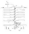
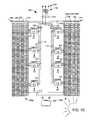
- FIG. 1Ais a schematic representation of a grid tie system according to an embodiment of the present invention.
- FIG. 1Bis a top plan view of the grid tie system of FIG. 1A ;
- FIG. 1Cis a perspective view of the grid tie system of FIG. 1A ;
- FIG. 2is a schematic representation of a series string of the grid tie system of FIGS. 1A-1C ;
- FIG. 3is a schematic representation of a disconnect box of the grid tie system of FIGS. 1A-1C ;
- FIG. 4is a schematic representation of a first clamping circuit of the grid tie system of FIGS. 1A-1C ;
- FIG. 5is a schematic representation of a second clamping circuit of the grid tie system of FIGS. 1A-1C ;
- FIG. 6is a schematic representation of a third clamping circuit of the grid tie system of FIGS. 1A-1C ;
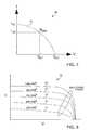
- FIG. 7is a graphical representation of electrical characteristics of a solar panel during a “one sun” illumination
- FIG. 8is a graphical representation of electrical characteristics of a solar panel during a varying illumination
- FIG. 9is a graphical representation of electrical characteristics of the grid tie system of FIGS. 1A-1C , showing a dynamic toggling of a plurality of inverters;
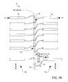
- FIG. 10is a schematic representation of a grid tie system according to another embodiment of the present invention.
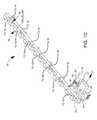
- FIG. 11is a schematic representation of a grid tie system according to another embodiment of the present invention.
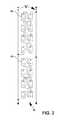
- FIG. 12Ais a perspective view of a transformer of the grid tie system of FIG. 11 ;
- FIG. 12Bis a side elevational view of the transformer of FIG. 12A .
- FIGS. 1A-1C and 2illustrate a grid tie system 10 (also known as a grid tie solar system or grid tie photovoltaic (PV) system) for harvesting solar energy according to an embodiment of the present invention.
- the system 10includes two portions 12 a , 12 b , each of which includes a plurality of rows 14 , wherein the rows 14 are collectively referred to as a solar array.
- each row 14includes a plurality of series strings 16 .
- each of the strings 16includes a plurality of solar panels 18 that are wired together in series.
- the strings 16 making up each of the rows 14are wired together in parallel.
- each of the strings 16includes six of the solar panels 18 wired in series to operate at approximately a voltage of 372 VDC, an operating current of 0.87 amps, and an open circuit voltage of 500 VDC.
- each of the strings 16includes eight of the solar panels 18 wired in series to operate at approximately a voltage of 496 VDC, an operating current of 1.16 amps, and an open circuit voltage of 672 VDC.
- each of the strings 16includes ten of the solar panels 18 to operate at approximately a voltage of 620 VDC, a current of 2.03 amps, and at an open circuit voltage of 840 VDC. It is understood that any number of the strings 16 and the panels 18 can be used to form a solar array.
- each of the portions 12 a , 12 bincludes forty-four of the rows 14 , each of the rows 14 includes twenty of the strings 16 , and each of the strings 16 includes eight of the solar panels 18 . Accordingly, the system 10 includes eighty-eight of the rows 14 , wherein each of the rows 14 includes one hundred and sixty of the panels 18 .
- the present inventionis not limited by the number or configuration of the array portions 12 a , 12 b , the rows 14 , the strings 16 , or the panels 18 .
- the system 10further includes a direct current conduction bus 20 (DC bus) in electrical communication with each of the strings 16 , a plurality of inverters 22 in electrical communication with the DC bus 20 , wherein each of the inverters 22 has an active state and an inactive state, an alternating current conduction bus 24 (AC bus) in electrical communication with each of the inverters 22 ; an electrical transformer 26 in communication with the AC bus 24 to receive an alternating current therefrom and step up the AC output voltage to match the distribution lines of an AC grid 28 , and a controller 30 in communication with at least one of the inverters 22 for selectively toggling the at least one of the inverters 22 between the active state and the inactive state.
- DC busdirect current conduction bus 20
- AC busalternating current conduction bus
- the DC bus 20is substantially linear. However, other configurations such as a ring shape can be used.
- Each of the rows 14is electrically connected to the DC bus 20 in a parallel configuration to transmit a DC current therethrough. However, other electrical configurations can be used.
- the inverters 22are electrically coupled to the DC bus 20 to receive a DC current (input) and convert the DC current into an output AC current, wherein the AC current is transmitted to the AC bus 24 .
- the direct wiring connection 57 from the DC bus 20 to a DC input of each of the inverters 22is no more than ten feet (three meters) and the direct wiring from the output of each of the inverters 22 to the AC bus 24 is by way of a “pig tail” cable 59 of approximately ten feet.
- any configuration using any length of wiring between the inverters 22 , the DC bus 20 , and the AC bus 24can be used.
- At least one of the inverters 22includes a maximum power point tracker (MPPT) 31 to track a maximum power point of at least one of the solar panels 18 .
- MPPT 31can be any type of control circuit, device, or logic to adjust the settings of the inverter to search for a maximum power point and allow the at least one of the inverters 22 to extract the maximum power available from an associated device (i.e. the row 14 , the string 16 , the panel 18 , etc.).
- the inverters 22are utilized on an as-needed basis to convert the DC input and transmit an output power. Any number of the inverters 22 are selectively toggled between an active state and an inactive state by the controller 30 (e.g. programmable logic controller (PLC)). As a non-limiting example, the controller 30 is in signal communication with each of the inverters 22 by way of one or more RS485 serial communications protocol connectors (S 1 -S 7 ). Other connectors and protocols can be used. As a further non-limiting example, each of the inverters 22 includes an air inlet 32 for thermal management.
- PLCprogrammable logic controller
- the AC bus 24is substantially linear. However, other configurations can be used.
- Each of the inverters 22is electrically connected to the AC bus 24 in a parallel configuration to transmit an AC current therethrough. However, other electrical configurations can be used.
- the AC bus 24includes a contactor/disconnect 33 that conducts the AC current to the transformer 26 . It is understood that other switches and relays can be used to conduct the AC current to the transformer 26 .
- the transformer 26steps up an input voltage so that an AC output voltage matches the distribution lines of the AC grid 28 .
- the transformer 26galvanically isolates the inverters 22 from the electrical AC grid 28 , which provides protection against islanding.
- FIGS. 1A-1Cincludes one of the transformers 26 , it is understood that any number of the transformers 26 can be used. It is further understood that the transformer 26 can be electrically integrated in any position in the system 10 (e.g. load side).
- a plurality of disconnect boxes 34 and a plurality of clamping circuits 36 a , 36 b , 36 care disposed between the rows 14 and the DC bus 20 .
- each of the disconnect boxes 34is disposed between at least one of the clamping circuits 36 a , 36 b , 36 c and the DC bus 20 . It is understood that any number of disconnect boxes 34 can be used.
- each of the disconnect boxes 34includes a double-pole, double-throw switch 38 interposed between the clamping circuit 36 a , 36 b , 36 c and the DC bus 20 .
- Each of the disconnect boxes 34includes a plurality of protection devices.
- the disconnect boxes 34provide over-current protection by way of a plurality of fuses F 1 , F 2 and lightning protection is provided by way of a plurality of metal oxide varistors MOV 1 , MOV 2 . It is understood that the placement of the disconnect boxes 34 at an output of each of the rows 14 minimizes the need to dispose fuses in each of the series strings 16 , as conventional solar arrays require. It is further understood that the disconnect boxes 34 allow any row 14 to be disconnected from the DC bus ring 20 for service or maintenance at any time.
- At least one of the clamping circuits 36 a , 36 b , 36 cmay be disposed between the rows 14 and the DC bus 20 to militate against a voltage of greater than 600 VDC being placed across the components within the solar panels 18 (e.g. a situation when the AC grid 28 “goes down” in the middle of a sunny day).
- voltage clampingcan be initiated manually, for example, in order to perform maintenance on an individual one of the rows 14 or when one or more of the rows 14 is/are not producing enough DC output.
- clampingcould be automatically commanded by, for example, the controller 30 .
- the clamping circuits 36 a , 36 b , 36 cmay be configured to clamp the voltage to any pre-determined voltage such as 600VDC and 1000 VDC, for example.
- FIG. 4illustrates the first clamping circuit 36 a including a double-pole, double-throw switch 40 .
- the contacts of a double-pole, double-throw switch 40short an incoming positive terminal from the output of an associated one of the rows 14 to an incoming negative terminal to place the associated one of the rows 14 in a short circuit condition.
- the short circuit conditionprotects the overall circuitry of the panels 18 from an overvoltage condition, for example.
- a controlling signalis received (either electrically from the controller 30 or by mechanical means) to toggle the switch 40 to allow the DC output current of the row 14 to flow to the DC bus 20 via one of the disconnect boxes 34 .
- FIG. 5illustrates the second clamping circuit 36 b including a gate-turn-off (GTO) thyristor 42 that is sized appropriately for the magnitude of the DC current lop being generated by one of the rows 14 .
- GTOgate-turn-off
- FIG. 6illustrates a third clamping circuit 34 c including a double-pole, double-throw switch 44 much like that of switch 40 .
- the third clamping circuit 36 cinstead of directly short circuiting the positive terminal of the incoming output of an associated one of the rows 14 to the incoming negative terminal, the third clamping circuit 36 c includes a resistor R disposed therebetween.
- the third clamping circuit 36 cfunctions similarly to that of the first clamping circuit 36 a but presents a voltage drop across the resistor R in order to limit a current that would flow therethrough.
- a controlling signalis received (e.g. from the controller 30 or by mechanical means) the contacts of the double-pole, double-throw switch 44 present the DC current output of the row 14 to the input of a disconnect box 34 .
- the clamping of, for example, one of the rows 14 of the strings 16minimizes the risk that the strings 16 experience a voltage that is greater than 600 VDC when the strings 16 are experiencing an open circuit condition, which is covered under the NEC.
- the system 10In use, the system 10 generates a DC current that is transmitted via the disconnect boxes 34 and clamping circuits 36 a , 36 b , 36 c to the inverters 22 .
- the inverters 22convert the DC current to an output AC current which is transmitted to the transformer 26 via the AC bus 24 .
- the transformer 26provides galvanic isolation and voltage step-up (from a nominal 360 V AC to the distribution voltage, typically 12,500 V AC) for the received output of the inverters 22 .
- the transformer 26provides separate impedance balanced primary windings for each of the inverters 22 .
- the cumulative operating current from each of the disconnect boxes 34is conducted, via the DC bus 20 , to the inverters 22 that are toggled to an “active” state.
- the controller 30determines a path that the DC output currents by cooperating with the inverters 22 to pass information back and forth to selectively determine which of the inverters 22 are to be turned on and off.
- the controller 30effectively directs the DC current to a select number of the inverters 22 for transforming the DC current to AC current to maximize the power output of the system 10 and to reduce power losses within the system 10 .
- the inverters 22 that are toggled to an “inactive” stateare typically disconnected from the AC bus 24 and the AC grid 28 to minimize quiescent losses, thereby maximizing an efficiency of the grid tie system 10 .
- FIGS. 7-8illustrate a characteristic curve 46 of typical electrical characteristics of one of the solar panels 18 , wherein I is current, V is voltage, I sc is short circuit current, I op is operation current, V op is operational voltage, V oc is open circuit voltage, and P max is a maximum power point.
- FIG. 7shows an IV (Current/Voltage) curve 48 of one of the solar panels 18 under “One Sun” illumination (i.e. the standard under which conventional solar panels are rated.) It is understood that there is only one point (i.e. the maximum power point) on the IV curve where the product of voltage and current (i.e. power) is maximized.
- the operating voltage (V op )is about 20% less than the open-circuit voltage (V oc ).
- FIG. 8illustrates a graphical representation 50 of the same one of the solar panels 18 represented in FIG. 7 under varying illumination.
- the currentvaries in direct proportion to the solar level.
- the open circuit voltageremains constant.
- Each of a plurality of IV curves 52has one point where the product of voltage and current is maximized (i.e. maximum power point).
- the inverters 22When brought on-line, the inverters 22 utilize distributed control to calculate an individual maximum power point (MPP) based upon a DC power received from an associated number of the strings 16 .
- MPPmaximum power point
- the inverters 22are controlled based upon a traditional “perturb and observe” algorithm.
- the controller 30toggles more of the inverters 22 to an “active” state.
- each of the inverters 22 that is toggled to an “Active” statedetermines an individual MPP that is utilized by that particular one of the inverters 22 , while leaving the other ones of the inverters 22 that are already online at essentially their maximum current point Imax.
- each of the inverters 22determines and safely handles its own current at any given time, while minimizing resistive losses of the incoming current.
- each of the inverter 22provides its own anti-islanding protection.
- FIG. 9shows a depiction of a dynamic toggling of the inverters 22 based on a summer day in Toledo, Ohio.
- a plurality of dashed linesrepresent an 85% power level for each of the inverters 22 , wherein at least a pair of the inverters 22 share a load proportionally.
- any number of the inverters 22can be toggled between the “active” and “inactive” state to share the load.
- the DC bus 20allows for any combination of the inverters 22 to be utilized in a virtually equal manner for inverting the collective DC output current of the rows 14 into an AC current that is conducted to the AC bus 24 . It is understood that a major benefit of the present invention is the transmission of a lower electrical current at a higher voltage, thereby minimizing a gage of required wiring and connecting devices, which consequently minimizes construction and maintenance costs.
- the strings 16include CdTe series-wired solar panels 18 (e.g. manufactured by First Solar, Incorporated of Phoenix, Ariz.) and have a nominal operation voltage on the order of 496 VDC to produce power on the order of 575 W.
- each row 14includes twenty of the strings 16
- each of the strings 16includes eight panels 18 wired in series to generate a current on the order of 23 A DC and 11.5 KW of power.
- the transformer 26would be presented with a voltage of 360 VAC—three phase, which is transformed on the utility side (i.e., on the side of the grid 28 ) of the transformer 26 to 12,470 V/7,200 V—three phase. It is understood that the output of the system 10 is in contrast to the conventional six panel wired in series that would present 277 VAC—three phase.
- each of the strings 16includes ten of the panels 18
- the nominal operational voltagewould be in the order of 620 VDC which would produce power in the order of 719 W.
- each row 14includes sixteen of the series strings 16 an output current in on the order of 18.6A DC and 11.5 KW of power.
- the transformer 26would be presented with a voltage of 480 VAC—three phase, which is transformed on the utility side (the grid 28 ) of the transformer 26 to the 12,470 V/7,200 V—three phase.
- FIG. 10illustrates a grid tie system 100 , also known as a grid tie solar system or grid tie photovoltaic (PV) system, according to another embodiment of the present invention similar to the system 10 , except as described herein below.
- the system 100includes two portions 102 a , 102 b each of which includes a plurality of rows 104 .
- each of the rows 104includes a plurality of series strings 106 .
- Each of the strings 106includes a plurality of solar panels 108 that are wired together in series.
- the strings 106 making up each of the rows 104are wired together in parallel. It is understood that any number of stings 106 and panels 108 can be used to form a solar array.
- the solar array 100further includes a direct current conduction bus 110 (DC bus) in electrical communication with each of the series wired panel strings 106 , a plurality of inverters 112 disposed adjacent the DC bus 110 and electrically coupled thereto, wherein each of the inverters 112 has an active state and an inactive state, an alternating current conduction bus 114 (AC bus) in electrical communication with each of the inverters 112 ; an electrical transformer 116 in communication with the AC bus 114 to receive an alternating current therefrom and step up the AC output voltage to match the distribution lines of an AC grid 118 , and a controller 120 in communication with at least one of the inverters 112 for selectively toggling the at least one of the inverters 112 between the active state and the inactive state.
- DC busdirect current conduction bus 110
- AC busalternating current conduction bus
- the DC bus 110is substantially ring shaped. However, other configurations such as a horseshoe shape can be used. Each of the rows 104 is electrically connected to the DC bus 110 in a parallel configuration to transmit a DC current therethrough. However, other electrical configurations can be used.
- the inverters 112are electrically coupled to the DC bus 110 to receive a DC current (input) and convert the DC current into an output AC current.
- at least one of the inverters 112includes a maximum power point tracker (MPPT) 121 to track a maximum power point of at least one of the solar panels 108 .
- MPPTmaximum power point tracker
- the MPPT 121can be any type of control circuit or logic to search for a maximum power point and allow the at least one of the inverters 112 to extract the maximum power available from an associated device (i.e. the row 104 , the string 106 , the panel 108 , etc.).
- the inverters 112are utilized on an as-needed basis to convert the DC input and transmit an output power.
- any number of the inverters 112are selectively toggled between an active state and an inactive state by the controller 120 (e.g. programmable logic controller (PLC)).
- the controller 120is in signal communication with each of the inverters 112 by way of RS485 serial communications protocol connectors (S 1 -S 8 ). Other connectors and protocols can be used. It is understood that by centrally locating the inverters 112 within the ring of the DC bus 110 , a wire gauge used for interconnection between the inverters 112 and the DC bus 110 is minimized.
- the AC bus 114is substantially horseshoe shaped. However, other configurations such as a ring shape can be used.
- Each of the inverters 112is electrically connected to the AC bus 114 in a parallel configuration to transmit an AC current therethrough. However, other electrical configurations can be used.
- the AC bus 114includes a contactor/disconnect 122 that conducts the AC current to the transformer 116 . It is understood that other switches and relays can be used to conduct the DC current to the transformer 116 .
- the transformer 116steps up an input voltage so that an AC output voltage matches the distribution lines of the AC grid 118 . Instead of multiple transformers (i.e., one transformer on the output of each of the conventional inverters), as conventional solar arrays require, the single large utility scale transformer 116 steps up the AC output voltage to match the distribution lines of the AC grid 118 .
- the single transformer 116galvanically isolates the inverters 112 from the electrical AC grid 118 , which provides protection against islanding.
- a plurality of disconnect boxes 124 and a plurality of clamping circuits 126 a , 126 b , 126 care disposed between the rows 104 and the DC bus 110 .
- each of the disconnect boxes 124is disposed between at least one of the clamping circuits 126 a , 126 b , 126 c and the DC bus 110 .
- any number of disconnect boxes 124can be used. It is understood that the placement of the disconnect boxes 124 at an output of each of the rows 104 minimizes the need to dispose fuses in each of the series strings 106 , as conventional solar arrays require. It is further understood that the disconnect boxes 124 allow any row 104 to be disconnected from the DC bus ring 110 for service or maintenance at any time.
- the clamping circuits 124 a , 124 b , 124 cmay be disposed between the rows 104 and the DC bus 110 to militate against a open circuit voltage of greater than 600 VDC being placed across the components within the solar panels 108 such as a situation when the AC grid 118 were to “go down” in the middle of a sunny day.
- voltage clampingcan be initiated manually, for example, in order to perform maintenance on an individual row or when one of the rows 104 is not producing enough DC output.
- clampingcould be automatically commanded by, for example, the controller 120 .
- a disconnect boxis dispose between the clamping circuit 124 a , 124 b , 124 c and the DC bus 110 .
- the solar panels 108generate a DC voltage in response to exposure to solar energy.
- At least one of the inverters 112senses the presence of the generated DC voltage and draws an electrical current which causes the DC voltage of at least one of the solar panels 108 to drop.
- the at least one inverter 112executes a “perturb and observe” routine to locate a maximum power point of at least one of the solar panels 108 .
- the “perturb and observe” routinemay include varying a voltage and measuring a change in a resultant current. It is further understood that any “perturb and observe” routine or algorithm can be used.
- the at least one of the inverters 112“locks” onto the maximum power point by maintaining the voltage-to-current ratio, conventionally referred to as maximum power point tracking.
- the inverters 112convert the DC current to an output AC current which is transmitted to the transformer 112 .
- the transformer 116provides galvanic isolation and voltage step-up (from a nominal 360 V AC to the distribution voltage, typically 12,500 V AC) for the received output of the inverters 112 .
- the transformer 116provides separate impedance balanced primary windings for each of the inverters 112 .
- FIG. 11illustrates a solar array 200 , also known as a grid tie solar system or grid tie photovoltaic (PV) system, according to another embodiment of the present invention similar to the grid tie system 10 .
- the grid tie system 200includes a plurality of solar panels 202 (e.g. arranged in series to form solar strings).
- the solar panels 202are connected in parallel to a DC bus 204 and in electrical communication with a plurality of inverters 206 . It is understood that any number of the solar panels 202 and the inverters 206 can be used. It is further understood that any electrical configuration can be used.
- the solar panels 202 and the inverters 206are arranged in a configuration similar to the configuration of the system 10 or the system 100 .
- the inverters 206are electrically coupled to the solar panels 202 to receive a DC current (input) and convert the DC current into an output AC current.
- at least one of the inverters 206includes a maximum power point tracker (MPPT) 207 to track a maximum power point of at least one of the solar panels 202 .
- MPPTmaximum power point tracker
- the MPPT 207can be any type of control circuit or logic to search for a maximum power point and allow the at least one of the inverters 206 to extract the maximum power available from an associated device (i.e. any number of the solar panels 202 ).
- a circuit 208is interposed between at least one of the solar panels 202 and at least one of the inverters 206 .
- the circuit 208includes a disconnect box (not shown) similar to the disconnect box 34 of the system 10 .
- the circuit 208includes a clamping circuit (not shown) similar to one of the clamping circuits 36 a , 36 b , 36 c of the system 10 . It is understood that any number of the circuits 208 can be used.
- the inverters 206are utilized on an as-needed basis to convert the DC input and transmit an output power. In certain embodiments, any number of the inverters 206 are selectively toggled between an active state and an inactive state by a controller 209 (e.g. programmable logic controller (PLC)).
- a controller 209e.g. programmable logic controller (PLC)
- the grid tie system 200further includes at least one transformer 210 coupled to an output of each of the inverters 206 .
- the transformer 210is a delta-wye isolation transformer having a plurality of electrically parallel delta primary windings and a wye secondary winding. Each of the delta primary windings is electrically coupled to an AC output of one of the inverters 206 and the secondary winding is electrically coupled to a distribution line.
- the transformer 210is similar to the utility transformer shown and described in U.S. Provisional Pat. Appl. Ser. No. 61/267,192.
- FIGS. 12A and 12Billustrate the transformer 210 according to an embodiment of the present invention.
- the transformeris a delta-wye isolation transformer having a plurality of electrically parallel delta primary windings and a wye secondary winding.
- Each of the delta primary windingsis electrically coupled to an AC output of one of the inverters 206 via at least one of a plurality of primary connectors 214 .
- the secondary windingis electrically coupled to a distribution line via at least one of a plurality of secondary connectors 216 . It is understood that various electrical connections between the inverters, the transformer, and the distribution line to the grid can provide various step-up transformations.
- the solar panels 202generate a DC voltage in response to exposure to solar energy.
- At least one of the inverters 206senses the presence of the generated DC voltage and draws an electrical current which causes the DC voltage of at least one of the solar panels 202 to drop.
- the at least one inverter 206executes a “perturb and observe” routine to locate a maximum power point of the solar panels 202 .
- the perturb and observe routinemay include varying a voltage and measuring a change in a resultant current. It is further understood that any perturb and observe routine or algorithm can be used.
- the at least one of the inverters 206“locks” onto the maximum power point by maintaining the voltage-to-current ratio, conventionally referred to as maximum power point tracking.
- the inverters 206are toggled from an inactive state to an active state on an “as needed” basis in response to a pre-determined and variable power level. Ideally, only one of the inverters 206 manages the maximum power point for the entire system 200 , as described above.
- the controller 209selectively toggles one of the inverters 206 (referred to as a master inverter 212 ) into an active state.
- each of the inverters 206includes an embedded component (e.g. control circuit) in communication with the controller 209 to transmit a feedback signal to the controller 209 having information relating to an operating characteristic or history of an associated one of the inverters 206 .
- the feedback signalincludes information relating to: an inverter “time online”; an inverter mode (controllable from the controller 209 : maximum power point tracking mode or a specific current output); a current out reading; a DC voltage In reading; an AC voltage in reading; an error/faults experienced by the inverter; a power produced year to date; and a power produced (by month, day, hour, minute, etc.).
- the controller 209queries each of the inverters 206 , receives a feedback signal therefrom, and analyzes the information represented by the feedback signal to select a master inverter from the queried inverters 206 .
- the controller 209is pre-programmed to select the one of the inverters 206 having the lowest “time online”.
- the controller 209can be programmed to select the master inverter 212 based upon any parameters or analysis.
- the master inverter 212is the one of the inverters 206 that manages the maximum power point for the system 200 for a pre-determined time period.
- additional ones of the inverters 206referred to as non-master inverters 213
- the additional non-master inverters 213draw current; however, the master inverter 212 continues to track the maximum power point of the solar panels 202 .
- the master inverter 212 that is managing the maximum power point (MPP)is capable of running to a limit of 150 KVA at (240 A).
- the master inverter 212is driven until approximately 80% of the 240 A limit is reached.
- the next one of the non-master inverters 213 in the hierarchy(typically determined based upon the query by the controller 209 ), is toggled to an active state and driven to approximately 80% of an associated current limit (240 A). It is understood that any percentage of the current or power limit can be used as a threshold value.
- the master inverter 212is adjusted to approximately 20% of the 240 A limit to maintain management of the MPP.
- the master inverter 212continues to track the maximum power point until again the master inverter 212 is driven to approximately 80% of the 240 A limit. At that point, the next one of the non-master inverters 213 in the hierarchy is toggled to an active state and driven to approximately 80% of an associated limit.
- the master inverter 212continues to manage the MPP, while the active non-master inverters 213 cooperate with the master inverter 212 to manage or “digest” the available current. As the master inverter 212 reaches approximately 80% of the current limit, one of the active non-master inverters 213 (e.g.
- the second one of the inverters 206 to be activatedis driven to nearly 100% of the current limit, the MPP is monitored, and the level of the master inverter 212 is modified by changing an output of at least one of the non-master inverters 213 . It is understood that on a day with intermittent cloud cover, the solar power will vary throughout the day. Accordingly, a time constant or threshold is introduced to eliminate excessive toggling and switching of the inverters 206 .
- the “active” inverters 206are adjusted to receive a DC current, convert the DC current to an output AC current, and transmit the AC current to the transformer 210 .
- the transformer 210combines two functions into one package.
- the primary function of the transformer 210is to provide galvanic isolation and voltage step-up (from a nominal 360 VAC to the distribution voltage, typically 12,500 VAC) for the received output of the inverters 210 .
- the secondary function of the transformer 210is to provide separate impedance balanced primary windings for each of the inverters 206 .
- the grid tie system 200 including the controller 209effectively “rotates” the inverters 206 to maintain nearly equal running hours between each of the inverters 206 in the system 200 . Accordingly, the grid tie system 200 and method of controlling the system 200 : maximizes a harvest of energy under low light level conditions; maximizes a reliability by selectively toggling each of the inverters 206 on an “as-needed” basis; and re-routes power in the event of a failure of one of the inverters 206 .
- the eight or ten solar panels being wired in seriesprovide approximately 30% higher voltage than conventional grid tie solar systems, which translates into higher efficiencies with lower gage wire sizes (i.e., at least one AWG copper wire size less than that required for the conventional six series wired panel string).
- each inverter 22 , 112 , 206may be switched on and off on an as-needed basis, the accumulated runtime of each inverter 22 , 112 , 206 is greatly reduced.
- each inverter 22 , 112 , 206 of the present inventionmay only be utilized for 7.5 years of the 20 year life span of a solar array, as opposed to the life span of inverters of a conventional solar array which are typically on continuously throughout the life of a conventional solar array.
- the remaining inverters 22 , 112 , 206will pick up the output current.
- an inverteris defective, it must be replaced in order to collect the output current from the rows that are wired to that particular inverter.
- invertersare most efficient when they are running at or near their peak power rating. For a conventional solar array, where an inverter is only operating at 10% of rated power, the inverter may only be 85% efficient. In the present invention, the inverters 22 , 112 , 206 that would currently be turned on would consistently deliver energy at or greater than 96% efficiency.
- the inverters 22 , 112 , 206on an as-needed-basis lowers costs and results in improving the inverter efficiency rates, for example, the inverters can be taken off-line at night. Also, interstage and inter-inverter transformers are not disposed with the inverters 22 , 112 , 206 of the present invention, thus resulting in lowering equipment, installation, and maintenance costs. In short, the present invention results in fewer components within the system 10 , 100 , 200 , which translates into higher power efficiencies.
Landscapes
- Engineering & Computer Science (AREA)
- Power Engineering (AREA)
- Life Sciences & Earth Sciences (AREA)
- Sustainable Development (AREA)
- Sustainable Energy (AREA)
- Electromagnetism (AREA)
- Physics & Mathematics (AREA)
- General Physics & Mathematics (AREA)
- Radar, Positioning & Navigation (AREA)
- Automation & Control Theory (AREA)
- Supply And Distribution Of Alternating Current (AREA)
- Inverter Devices (AREA)
- Control Of Electrical Variables (AREA)
Abstract
Description
Claims (17)
Priority Applications (2)
| Application Number | Priority Date | Filing Date | Title |
|---|---|---|---|
| US12/752,254US8779627B2 (en) | 2009-04-01 | 2010-04-01 | Grid tie solar system and a method |
| US14/306,983US8963373B2 (en) | 2009-04-01 | 2014-06-17 | Grid tie solar system and a method |
Applications Claiming Priority (4)
| Application Number | Priority Date | Filing Date | Title |
|---|---|---|---|
| US21164909P | 2009-04-01 | 2009-04-01 | |
| US26719209P | 2009-12-07 | 2009-12-07 | |
| US30403610P | 2010-02-12 | 2010-02-12 | |
| US12/752,254US8779627B2 (en) | 2009-04-01 | 2010-04-01 | Grid tie solar system and a method |
Related Child Applications (1)
| Application Number | Title | Priority Date | Filing Date |
|---|---|---|---|
| US14/306,983DivisionUS8963373B2 (en) | 2009-04-01 | 2014-06-17 | Grid tie solar system and a method |
Publications (2)
| Publication Number | Publication Date |
|---|---|
| US20100253151A1 US20100253151A1 (en) | 2010-10-07 |
| US8779627B2true US8779627B2 (en) | 2014-07-15 |
Family
ID=42825588
Family Applications (2)
| Application Number | Title | Priority Date | Filing Date |
|---|---|---|---|
| US12/752,254Expired - Fee RelatedUS8779627B2 (en) | 2009-04-01 | 2010-04-01 | Grid tie solar system and a method |
| US14/306,983Expired - Fee RelatedUS8963373B2 (en) | 2009-04-01 | 2014-06-17 | Grid tie solar system and a method |
Family Applications After (1)
| Application Number | Title | Priority Date | Filing Date |
|---|---|---|---|
| US14/306,983Expired - Fee RelatedUS8963373B2 (en) | 2009-04-01 | 2014-06-17 | Grid tie solar system and a method |
Country Status (6)
| Country | Link |
|---|---|
| US (2) | US8779627B2 (en) |
| EP (1) | EP2415146A1 (en) |
| KR (1) | KR20120017416A (en) |
| CN (1) | CN102449896B (en) |
| CA (1) | CA2757331A1 (en) |
| WO (1) | WO2010114995A1 (en) |
Cited By (4)
| Publication number | Priority date | Publication date | Assignee | Title |
|---|---|---|---|---|
| US20160028271A1 (en)* | 2014-07-22 | 2016-01-28 | Rick Smith | Grid tie charge controller |
| US11264807B2 (en) | 2019-09-30 | 2022-03-01 | James Arnim White | Renewable energy metering system |
| USD1011272S1 (en) | 2020-07-28 | 2024-01-16 | Palm Energy Systems Llc | Solar collector pillar |
| US12015375B2 (en) | 2014-09-09 | 2024-06-18 | Shoals Technologies Group, Llc | Lead assembly for connecting solar panel arrays to inverter |
Families Citing this family (41)
| Publication number | Priority date | Publication date | Assignee | Title |
|---|---|---|---|---|
| US9407093B2 (en) | 2007-08-22 | 2016-08-02 | Maxout Renewables, Inc. | Method for balancing circuit voltage |
| US8933320B2 (en) | 2008-01-18 | 2015-01-13 | Tenksolar, Inc. | Redundant electrical architecture for photovoltaic modules |
| US8212139B2 (en) | 2008-01-18 | 2012-07-03 | Tenksolar, Inc. | Thin-film photovoltaic module |
| US8748727B2 (en) | 2008-01-18 | 2014-06-10 | Tenksolar, Inc. | Flat-plate photovoltaic module |
| CN102460338B (en) | 2009-05-19 | 2014-08-13 | 最大输出可再生能源公司 | Construction of a power station comprising a cluster of power generating units |
| WO2010148009A2 (en) | 2009-06-15 | 2010-12-23 | Tenksolar, Inc. | Illumination agnostic solar panel |
| US8564916B2 (en)* | 2010-02-16 | 2013-10-22 | Western Gas And Electric Company | Photovoltaic array ground fault detection method for utility-scale grounded solar electric power generating systems |
| US8618456B2 (en)* | 2010-02-16 | 2013-12-31 | Western Gas And Electric Company | Inverter for a three-phase AC photovoltaic system |
| US9773933B2 (en) | 2010-02-23 | 2017-09-26 | Tenksolar, Inc. | Space and energy efficient photovoltaic array |
| US9299861B2 (en) | 2010-06-15 | 2016-03-29 | Tenksolar, Inc. | Cell-to-grid redundandt photovoltaic system |
| US9118213B2 (en) | 2010-11-24 | 2015-08-25 | Kohler Co. | Portal for harvesting energy from distributed electrical power sources |
| ITVI20110112A1 (en)* | 2011-04-29 | 2012-10-30 | Itaco S R L | PHOTOVOLTAIC PLANT FOR THE PRODUCTION OF ELECTRIC POWER OF HIGH POWER |
| US9531293B2 (en) | 2011-07-11 | 2016-12-27 | Sinewatts, Inc. | Systems and methods for solar photovoltaic energy collection and conversion |
| FR2981218A1 (en)* | 2011-10-10 | 2013-04-12 | Farid Marouani | Method for supplying power to inverters in e.g. electricity production installation, involves selectively feeding supply in accordance with electric parameter by simple commutation of feeding attachment between installation and inverters |
| WO2013066998A1 (en)* | 2011-10-31 | 2013-05-10 | Tenksolar Inc. | Cell-to-grid redundant photovoltaic system |
| TWI448034B (en)* | 2011-12-19 | 2014-08-01 | Darfon Electronics Corp | Solar inverter system and control method thereof |
| US20130234520A1 (en)* | 2012-03-07 | 2013-09-12 | Nicole Dierksheide | Modular energy portal with ac architecture for harvesting energy from electrical power sources |
| GB201207915D0 (en)* | 2012-05-04 | 2012-06-20 | Control Tech Ltd | Thermal model |
| US9287418B2 (en)* | 2012-06-29 | 2016-03-15 | Eaton Corporation | System and method for connection of photovoltaic arrays in series and parallel arrangements |
| US8648498B1 (en)* | 2012-11-19 | 2014-02-11 | Renewable Power Conversion, Inc | Photovoltaic power system with distributed photovoltaic string to polyphase AC power converters |
| CN102983185B (en)* | 2012-12-07 | 2015-05-20 | 阮仕荣 | Common-base solar panel and direct current supercharging device thereof |
| US20140217832A1 (en)* | 2013-02-06 | 2014-08-07 | Astec International Limited | Disconnect switches in dc power systems |
| US9270164B2 (en) | 2013-06-19 | 2016-02-23 | Tmeic Corporation | Methods, systems, computer program products, and devices for renewable energy site power limit control |
| JP6140044B2 (en)* | 2013-09-27 | 2017-05-31 | 株式会社日立製作所 | Power generation system and power generation system design method |
| US9728974B2 (en) | 2013-10-10 | 2017-08-08 | Tmeic Corporation | Renewable energy site reactive power control |
| WO2015156901A1 (en)* | 2014-04-11 | 2015-10-15 | Kripya LLC | Dual mode micro-inverter system and operation |
| US9590528B2 (en) | 2014-04-11 | 2017-03-07 | Kripya LLC | Dual mode DC-AC inverter system and operation |
| CN104184164B (en)* | 2014-05-30 | 2017-06-06 | 上海吉亿电机有限公司 | A kind of anti-grid disturbance method of grid-connected pwm converter |
| EP2975757A1 (en) | 2014-07-14 | 2016-01-20 | ABB Technology AG | Three-phase transformerless DC to AC inverter |
| US9927827B2 (en)* | 2014-08-12 | 2018-03-27 | Sunpower Corporation | Electrical independence of tracker rows |
| US10447040B2 (en) | 2014-10-15 | 2019-10-15 | Cummins Power Generation Ip, Inc. | Programmable inverter for controllable grid response |
| US10187115B2 (en)* | 2015-07-13 | 2019-01-22 | Maxim Integrated Products, Inc. | Systems and methods for DC power line communication in a photovoltaic system |
| US10938218B2 (en) | 2015-12-28 | 2021-03-02 | Sunpower Corporation | Solar tracker system |
| US10566798B2 (en)* | 2016-03-31 | 2020-02-18 | Texas Instruments Incorporated | Solar panel disconnect and reactivation system |
| KR102488002B1 (en) | 2018-04-05 | 2023-01-13 | 한국전자통신연구원 | Power conversion system and operating method thereof |
| US10630190B2 (en)* | 2018-08-13 | 2020-04-21 | University Of Central Florida Research Foundation, Inc. | Multi-input single-resonant tank LLC converter |
| US11005390B2 (en)* | 2018-11-26 | 2021-05-11 | Northrop Grumman Systems Corporation | AC power transfer over self-passivating connectors |
| KR102283826B1 (en)* | 2019-07-03 | 2021-08-02 | 주식회사 네모엘텍 | PV module serial/parallel conversion system for MPPT operating voltage optimization based on machine learning |
| US11545931B2 (en) | 2019-11-10 | 2023-01-03 | Maxout Renewables, Inc. | Optimizing hybrid inverter system |
| EP4367771A4 (en)* | 2021-07-08 | 2025-02-26 | Nextracker LLC | COMMON DC BUS AND COMMON AC BUS POWER ELECTRONICS SYSTEMS AND METHODS |
| US20230216300A1 (en)* | 2021-12-03 | 2023-07-06 | Nextracker Llc | Fixed dc bus power electronic systems and methods |
Citations (45)
| Publication number | Priority date | Publication date | Assignee | Title |
|---|---|---|---|---|
| US3922639A (en) | 1973-08-28 | 1975-11-25 | Toyo Tire & Rubber Co | Multiple input signal detecting device |
| US4285481A (en) | 1979-06-04 | 1981-08-25 | Biscomb Lloyd I | Multiple wind turbine tethered airfoil wind energy conversion system |
| US4591965A (en) | 1984-10-19 | 1986-05-27 | Dickerson Arthur F | Inverter for use with solar arrays |
| US4680690A (en) | 1984-10-19 | 1987-07-14 | Dickerson Arthur F | Inverter for use with solar arrays |
| US5268832A (en) | 1991-08-20 | 1993-12-07 | Kabushiki Kaisha Toshiba | DC/AC inverter controller for solar cell, including maximum power point tracking function |
| US5289998A (en) | 1991-10-15 | 1994-03-01 | General Electric Co. | Solar array output regulator using variable light transmission |
| US5329172A (en) | 1991-11-08 | 1994-07-12 | Yamaha Corporation | Chopping type comparator with clocked inverter |
| US5977659A (en) | 1996-06-03 | 1999-11-02 | Canon Kabushiki Kaisha | Inverter apparatus and solar power generation apparatus |
| US6104624A (en)* | 1999-03-15 | 2000-08-15 | Mitsubishi Denki Kabushiki Kaisha | System connecting device |
| US6111767A (en) | 1998-06-22 | 2000-08-29 | Heliotronics, Inc. | Inverter integrated instrumentation having a current-voltage curve tracer |
| US6232742B1 (en) | 1994-08-02 | 2001-05-15 | Aerovironment Inc. | Dc/ac inverter apparatus for three-phase and single-phase motors |
| US6285572B1 (en)* | 1999-04-20 | 2001-09-04 | Sanyo Electric Co., Ltd. | Method of operating a power supply system having parallel-connected inverters, and power converting system |
| US20030054793A1 (en) | 2001-08-17 | 2003-03-20 | Manis Constantine N. | Coupling between power line and customer in power line communication system |
| US20030111103A1 (en)* | 2001-10-25 | 2003-06-19 | Bower Ward Issac | Alternating current photovoltaic building block |
| US6646196B2 (en) | 2001-11-26 | 2003-11-11 | Apogee Enterprises, Inc. | Window structure with photovoltaic panel |
| US20040147172A1 (en) | 2002-07-05 | 2004-07-29 | Brown Jacob E | Apparatus, system, and method of electrically coupling photovoltaic modules |
| US20040211546A1 (en) | 2000-08-07 | 2004-10-28 | Sivilotti Olivo G. | Belt-cooling and guiding means for continuous belt casting of metal strip |
| US20040264225A1 (en)* | 2003-05-02 | 2004-12-30 | Ballard Power Systems Corporation | Method and apparatus for determining a maximum power point of photovoltaic cells |
| US6853940B2 (en) | 2002-01-16 | 2005-02-08 | Ballard Power Systems Corporation | Anti-islanding device and method for grid connected inverters using random noise injection |
| US20050045224A1 (en) | 2003-08-29 | 2005-03-03 | Lyden Robert M. | Solar cell, module, array, network, and power grid |
| USD507528S1 (en) | 2004-11-12 | 2005-07-19 | Xantrex Technology Inc. | Solar powered inverter |
| CN1669208A (en) | 2002-07-15 | 2005-09-14 | 皇家飞利浦电子股份有限公司 | Inverter |
| US20050281064A1 (en)* | 2004-06-17 | 2005-12-22 | Olsen Ib I | Battery and inverter configuration with increased efficiency |
| US20060164065A1 (en) | 2005-01-24 | 2006-07-27 | Linear Technology Corporation | System and method for tracking a variable characteristic through a range of operation |
| US20060185727A1 (en)* | 2004-12-29 | 2006-08-24 | Isg Technologies Llc | Converter circuit and technique for increasing the output efficiency of a variable power source |
| US7112891B2 (en) | 2003-05-15 | 2006-09-26 | Sprint Communications Company L.P. | Mobile-power system with solar-powered hydrogen liberator, fuel cell, turbine, and capacitors |
| US7129592B1 (en) | 2005-03-02 | 2006-10-31 | Yetter Gary L | Portable, human-powered electrical energy source |
| US7193872B2 (en) | 2005-01-28 | 2007-03-20 | Kasemsan Siri | Solar array inverter with maximum power tracking |
| US20070103108A1 (en) | 2003-05-28 | 2007-05-10 | Beacon Power Corporation | Power converter for a solar panel |
| US7230819B2 (en) | 2002-09-13 | 2007-06-12 | Skybuilt Power, Llc | Mobile power system |
| US20070219932A1 (en) | 2006-03-15 | 2007-09-20 | Carroll Scott T | Cooperative energy farms and virtual net metering |
| US7274975B2 (en) | 2005-06-06 | 2007-09-25 | Gridpoint, Inc. | Optimized energy management system |
| US20070221267A1 (en)* | 2006-03-23 | 2007-09-27 | Pvi Solutions Inc. | Method and apparatus for converting direct current to alternating current |
| US20070252716A1 (en) | 2004-05-27 | 2007-11-01 | Roland Burger | Solar Inverter and Photovoltaic Installation Comprising Several Solar Inverters |
| US20070279863A1 (en) | 2006-06-01 | 2007-12-06 | Diehl Ako Stiftung & Co. Kg | Solar inverter assembly |
| CN101107442A (en) | 2005-02-17 | 2008-01-16 | 三菱重工业株式会社 | Generation system |
| US20080078436A1 (en) | 2006-09-28 | 2008-04-03 | Jack Nachamkin | Integrated voltaic energy system |
| US20080143462A1 (en)* | 2006-12-14 | 2008-06-19 | Hamilton Sundstrand Corporation | High voltage DC contactor hybrid without a DC arc break |
| US20080143188A1 (en) | 2006-12-06 | 2008-06-19 | Meir Adest | Distributed power harvesting systems using dc power sources |
| US20080238195A1 (en)* | 2007-03-27 | 2008-10-02 | Shaver Argil E | Distributed maximum power point tracking system, structure and process |
| US20090218888A1 (en)* | 2008-03-03 | 2009-09-03 | Lorhammer Kurt M | Power electronic architecture for managing fuel cell modules and method therefor |
| US20100091532A1 (en)* | 2008-10-10 | 2010-04-15 | Enphase Energy, Inc. | Method and apparatus for improved burst mode during power conversion |
| US20100283325A1 (en)* | 2007-06-06 | 2010-11-11 | Andrea Marcianesi | Delivery of Electric Power by Means of a Plurality of Parallel Inverters and Control Method Based on Maximum Power Point Tracking |
| US20110032099A1 (en)* | 2008-02-11 | 2011-02-10 | Siemens Ag | Method for Recognizing Theft of a PV Module and a Failure of a Bypass Diode of a PV Module, Corresponding PV Sub-Generator Junction Box, PV Inverter, and Corresponding PV System |
| US7999418B2 (en)* | 2008-12-22 | 2011-08-16 | General Electric Company | Electrical system and control method |
Family Cites Families (24)
| Publication number | Priority date | Publication date | Assignee | Title |
|---|---|---|---|---|
| GB9725128D0 (en)* | 1997-11-27 | 1998-01-28 | Weinberg Alan H | Solar array system |
| JP3545203B2 (en) | 1998-05-22 | 2004-07-21 | 三洋電機株式会社 | Inverter operation method and power supply system |
| US6670721B2 (en)* | 2001-07-10 | 2003-12-30 | Abb Ab | System, method, rotating machine and computer program product for enhancing electric power produced by renewable facilities |
| JP5208374B2 (en) | 2006-04-18 | 2013-06-12 | シャープ株式会社 | Grid interconnection power conditioner and grid interconnection power system |
| US7851943B2 (en)* | 2006-12-08 | 2010-12-14 | General Electric Company | Direct current power transmission and distribution system |
| KR100902507B1 (en)* | 2007-04-17 | 2009-06-15 | 삼성전자주식회사 | Power control device and its operation method |
| CN101765959B (en) | 2007-05-08 | 2015-04-15 | 美国电力转换有限公司 | AC Power Energy Management |
| US7728562B2 (en) | 2007-07-27 | 2010-06-01 | Gm Global Technology Operations, Inc. | Voltage link control of a DC-AC boost converter system |
| US7986122B2 (en) | 2007-09-26 | 2011-07-26 | Enphase Energy, Inc. | Method and apparatus for power conversion with maximum power point tracking and burst mode capability |
| DE102007054647A1 (en) | 2007-11-15 | 2009-06-18 | Siemens Ag | Solar inverter with several parallel single inverters and with a higher-level electronic control unit |
| TW201014146A (en) | 2008-05-14 | 2010-04-01 | Nat Semiconductor Corp | System and method for an array of intelligent inverters |
| US8872381B2 (en) | 2008-09-18 | 2014-10-28 | Sansha Electric Manufacturing Co., Ltd. | Utility interconnection and inverter device |
| US8008808B2 (en) | 2009-01-16 | 2011-08-30 | Zbb Energy Corporation | Method and apparatus for controlling a hybrid power system |
| EP2282388A1 (en) | 2009-08-06 | 2011-02-09 | SMA Solar Technology AG | Device for feeding in electrical energy of a number of strings of photovoltaic modules in an electricity network |
| KR101097260B1 (en) | 2009-12-15 | 2011-12-22 | 삼성에스디아이 주식회사 | Grid-connected energy storage system and method for controlling grid-connected energy storage system |
| US8836162B2 (en) | 2010-02-26 | 2014-09-16 | Ziehl-Abegg Ag | Inverter for photovoltaic systems |
| US9502904B2 (en) | 2010-03-23 | 2016-11-22 | Eaton Corporation | Power conversion system and method providing maximum efficiency of power conversion for a photovoltaic system, and photovoltaic system employing a photovoltaic array and an energy storage device |
| US8405251B2 (en)* | 2010-04-20 | 2013-03-26 | General Electric Company | Method and apparatus for reduction of harmonics in a power supply |
| US9118215B2 (en) | 2010-10-05 | 2015-08-25 | Alencon Acquistion Co., Llc | High voltage energy harvesting and conversion renewable energy utility size electric power systems and visual monitoring and control systems for said systems |
| US8970068B2 (en) | 2011-02-10 | 2015-03-03 | Draker, Inc. | Pseudo-random bit sequence generation for maximum power point tracking in photovoltaic arrays |
| US8493753B2 (en) | 2011-03-07 | 2013-07-23 | Allis Electric Co., Ltd. | Photovoltaic powered system |
| US9431825B2 (en) | 2011-07-28 | 2016-08-30 | Tigo Energy, Inc. | Systems and methods to reduce the number and cost of management units of distributed power generators |
| US8537581B2 (en) | 2011-08-25 | 2013-09-17 | General Electric Company | Power converter system and methods of operating a power converter system |
| WO2013075291A1 (en) | 2011-11-23 | 2013-05-30 | General Electric Company | Systems and methods for use in controlling a converter in response to grid fault events |
- 2010
- 2010-04-01CACA 2757331patent/CA2757331A1/ennot_activeAbandoned
- 2010-04-01KRKR1020117025861Apatent/KR20120017416A/ennot_activeWithdrawn
- 2010-04-01USUS12/752,254patent/US8779627B2/ennot_activeExpired - Fee Related
- 2010-04-01CNCN201080024079.1Apatent/CN102449896B/ennot_activeExpired - Fee Related
- 2010-04-01WOPCT/US2010/029623patent/WO2010114995A1/enactiveApplication Filing
- 2010-04-01EPEP10759403Apatent/EP2415146A1/ennot_activeWithdrawn
- 2014
- 2014-06-17USUS14/306,983patent/US8963373B2/ennot_activeExpired - Fee Related
Patent Citations (48)
| Publication number | Priority date | Publication date | Assignee | Title |
|---|---|---|---|---|
| US3922639A (en) | 1973-08-28 | 1975-11-25 | Toyo Tire & Rubber Co | Multiple input signal detecting device |
| US4285481A (en) | 1979-06-04 | 1981-08-25 | Biscomb Lloyd I | Multiple wind turbine tethered airfoil wind energy conversion system |
| US4591965A (en) | 1984-10-19 | 1986-05-27 | Dickerson Arthur F | Inverter for use with solar arrays |
| US4680690A (en) | 1984-10-19 | 1987-07-14 | Dickerson Arthur F | Inverter for use with solar arrays |
| US5268832A (en) | 1991-08-20 | 1993-12-07 | Kabushiki Kaisha Toshiba | DC/AC inverter controller for solar cell, including maximum power point tracking function |
| US5289998A (en) | 1991-10-15 | 1994-03-01 | General Electric Co. | Solar array output regulator using variable light transmission |
| US5329172A (en) | 1991-11-08 | 1994-07-12 | Yamaha Corporation | Chopping type comparator with clocked inverter |
| US6232742B1 (en) | 1994-08-02 | 2001-05-15 | Aerovironment Inc. | Dc/ac inverter apparatus for three-phase and single-phase motors |
| US5977659A (en) | 1996-06-03 | 1999-11-02 | Canon Kabushiki Kaisha | Inverter apparatus and solar power generation apparatus |
| US6111767A (en) | 1998-06-22 | 2000-08-29 | Heliotronics, Inc. | Inverter integrated instrumentation having a current-voltage curve tracer |
| US6104624A (en)* | 1999-03-15 | 2000-08-15 | Mitsubishi Denki Kabushiki Kaisha | System connecting device |
| US6285572B1 (en)* | 1999-04-20 | 2001-09-04 | Sanyo Electric Co., Ltd. | Method of operating a power supply system having parallel-connected inverters, and power converting system |
| US20040211546A1 (en) | 2000-08-07 | 2004-10-28 | Sivilotti Olivo G. | Belt-cooling and guiding means for continuous belt casting of metal strip |
| US20030054793A1 (en) | 2001-08-17 | 2003-03-20 | Manis Constantine N. | Coupling between power line and customer in power line communication system |
| US20030111103A1 (en)* | 2001-10-25 | 2003-06-19 | Bower Ward Issac | Alternating current photovoltaic building block |
| US6646196B2 (en) | 2001-11-26 | 2003-11-11 | Apogee Enterprises, Inc. | Window structure with photovoltaic panel |
| US6853940B2 (en) | 2002-01-16 | 2005-02-08 | Ballard Power Systems Corporation | Anti-islanding device and method for grid connected inverters using random noise injection |
| US20040147172A1 (en) | 2002-07-05 | 2004-07-29 | Brown Jacob E | Apparatus, system, and method of electrically coupling photovoltaic modules |
| CN1669208A (en) | 2002-07-15 | 2005-09-14 | 皇家飞利浦电子股份有限公司 | Inverter |
| US7031176B2 (en) | 2002-07-15 | 2006-04-18 | Koninklijke Philips Electronics N.V. | Inverter |
| US7230819B2 (en) | 2002-09-13 | 2007-06-12 | Skybuilt Power, Llc | Mobile power system |
| US20040264225A1 (en)* | 2003-05-02 | 2004-12-30 | Ballard Power Systems Corporation | Method and apparatus for determining a maximum power point of photovoltaic cells |
| US7112891B2 (en) | 2003-05-15 | 2006-09-26 | Sprint Communications Company L.P. | Mobile-power system with solar-powered hydrogen liberator, fuel cell, turbine, and capacitors |
| US20070103108A1 (en) | 2003-05-28 | 2007-05-10 | Beacon Power Corporation | Power converter for a solar panel |
| US20050045224A1 (en) | 2003-08-29 | 2005-03-03 | Lyden Robert M. | Solar cell, module, array, network, and power grid |
| US20070252716A1 (en) | 2004-05-27 | 2007-11-01 | Roland Burger | Solar Inverter and Photovoltaic Installation Comprising Several Solar Inverters |
| US20050281064A1 (en)* | 2004-06-17 | 2005-12-22 | Olsen Ib I | Battery and inverter configuration with increased efficiency |
| USD507528S1 (en) | 2004-11-12 | 2005-07-19 | Xantrex Technology Inc. | Solar powered inverter |
| US20060185727A1 (en)* | 2004-12-29 | 2006-08-24 | Isg Technologies Llc | Converter circuit and technique for increasing the output efficiency of a variable power source |
| US20060164065A1 (en) | 2005-01-24 | 2006-07-27 | Linear Technology Corporation | System and method for tracking a variable characteristic through a range of operation |
| US7193872B2 (en) | 2005-01-28 | 2007-03-20 | Kasemsan Siri | Solar array inverter with maximum power tracking |
| US7324361B2 (en) | 2005-01-28 | 2008-01-29 | Kasemsan Siri | Solar array inverter with maximum power tracking |
| US20090146423A1 (en)* | 2005-02-17 | 2009-06-11 | Mitsubishi Heavy Industries, Ltd | Power Generating System |
| CN101107442A (en) | 2005-02-17 | 2008-01-16 | 三菱重工业株式会社 | Generation system |
| US7129592B1 (en) | 2005-03-02 | 2006-10-31 | Yetter Gary L | Portable, human-powered electrical energy source |
| US7274975B2 (en) | 2005-06-06 | 2007-09-25 | Gridpoint, Inc. | Optimized energy management system |
| US20070219932A1 (en) | 2006-03-15 | 2007-09-20 | Carroll Scott T | Cooperative energy farms and virtual net metering |
| US20070221267A1 (en)* | 2006-03-23 | 2007-09-27 | Pvi Solutions Inc. | Method and apparatus for converting direct current to alternating current |
| US20070279863A1 (en) | 2006-06-01 | 2007-12-06 | Diehl Ako Stiftung & Co. Kg | Solar inverter assembly |
| US20080078436A1 (en) | 2006-09-28 | 2008-04-03 | Jack Nachamkin | Integrated voltaic energy system |
| US20080143188A1 (en) | 2006-12-06 | 2008-06-19 | Meir Adest | Distributed power harvesting systems using dc power sources |
| US20080143462A1 (en)* | 2006-12-14 | 2008-06-19 | Hamilton Sundstrand Corporation | High voltage DC contactor hybrid without a DC arc break |
| US20080238195A1 (en)* | 2007-03-27 | 2008-10-02 | Shaver Argil E | Distributed maximum power point tracking system, structure and process |
| US20100283325A1 (en)* | 2007-06-06 | 2010-11-11 | Andrea Marcianesi | Delivery of Electric Power by Means of a Plurality of Parallel Inverters and Control Method Based on Maximum Power Point Tracking |
| US20110032099A1 (en)* | 2008-02-11 | 2011-02-10 | Siemens Ag | Method for Recognizing Theft of a PV Module and a Failure of a Bypass Diode of a PV Module, Corresponding PV Sub-Generator Junction Box, PV Inverter, and Corresponding PV System |
| US20090218888A1 (en)* | 2008-03-03 | 2009-09-03 | Lorhammer Kurt M | Power electronic architecture for managing fuel cell modules and method therefor |
| US20100091532A1 (en)* | 2008-10-10 | 2010-04-15 | Enphase Energy, Inc. | Method and apparatus for improved burst mode during power conversion |
| US7999418B2 (en)* | 2008-12-22 | 2011-08-16 | General Electric Company | Electrical system and control method |
Cited By (7)
| Publication number | Priority date | Publication date | Assignee | Title |
|---|---|---|---|---|
| US20160028271A1 (en)* | 2014-07-22 | 2016-01-28 | Rick Smith | Grid tie charge controller |
| US9948137B2 (en)* | 2014-07-22 | 2018-04-17 | Rick Smith | Grid tie charge controller |
| US12015375B2 (en) | 2014-09-09 | 2024-06-18 | Shoals Technologies Group, Llc | Lead assembly for connecting solar panel arrays to inverter |
| US12015376B2 (en) | 2014-09-09 | 2024-06-18 | Shoals Technologies Group, Llc | Lead assembly for connecting solar panel arrays to inverter |
| US12407295B2 (en) | 2014-09-09 | 2025-09-02 | Shoals Technologies Group, Llc | Lead assembly for connecting solar panel arrays to inverter |
| US11264807B2 (en) | 2019-09-30 | 2022-03-01 | James Arnim White | Renewable energy metering system |
| USD1011272S1 (en) | 2020-07-28 | 2024-01-16 | Palm Energy Systems Llc | Solar collector pillar |
Also Published As
| Publication number | Publication date |
|---|---|
| KR20120017416A (en) | 2012-02-28 |
| CN102449896A (en) | 2012-05-09 |
| US20100253151A1 (en) | 2010-10-07 |
| CA2757331A1 (en) | 2010-10-07 |
| WO2010114995A1 (en) | 2010-10-07 |
| EP2415146A1 (en) | 2012-02-08 |
| CN102449896B (en) | 2014-12-10 |
| US20140327314A1 (en) | 2014-11-06 |
| US8963373B2 (en) | 2015-02-24 |
Similar Documents
| Publication | Publication Date | Title |
|---|---|---|
| US8963373B2 (en) | Grid tie solar system and a method | |
| US8106537B2 (en) | Photovoltaic DC/DC micro-converter | |
| Salas et al. | Overview of the off-grid photovoltaic diesel batteries systems with AC loads | |
| CN101375482B (en) | Power supply system | |
| US20150229131A1 (en) | Grid tie solar inverter system with storage | |
| CN103733474B (en) | For generating, storing and supply by the system of the electric energy of modularization DC makers generation and the correlation technique for managing the system | |
| WO2007086472A1 (en) | Power supply system | |
| US11888442B2 (en) | Solar modules having solar sub cells with matrix connections between the solar sub cells | |
| CN101904015A (en) | Efficient solar energy system capable of being remotely controlled | |
| Franklin | Solar photovoltaic (PV) system components | |
| CN114402526A (en) | Equipment, method and device for obtaining maximum charging current by series-parallel hybrid connection of photovoltaic arrays by using branching | |
| CA2784044C (en) | System for the electronic management of photovoltaic cells as a function of meteorology | |
| Adesina et al. | Design, implementation and performance analysis of an off-grid solar powered system for a Nigerian household | |
| Martirano et al. | Implementation of SCADA systems for a real microgrid lab testbed | |
| US8525369B2 (en) | Method and device for optimizing the use of solar electrical power | |
| Krzywinski | Integrating storage and renewable energy sources into a DC Microgrid using high gain DC DC Boost Converters | |
| KR20220012209A (en) | Photovoltaic power generation device with excess power optimization function and Method thereof | |
| Abou Jieb et al. | Solar system components | |
| KR101983759B1 (en) | Connection box of solar power generation system and control method thereof | |
| Pandey et al. | Analysis of Solar Photovoltaic Systems for Optimum Utilization in Microgrid Applications | |
| Khanfara et al. | Economic Sizing of a Grid-Connected Photovoltaic System: Case of GISER research project in Morocco | |
| Vallejos et al. | Enhancing Power Balancing and Fault Interruption in an Autonomous Smart Microgrid Design | |
| Al-Juboori | Stand-Alone Photovoltaic System | |
| Nayar et al. | Power conditioning for photovoltaic power systems | |
| HUSSAIN et al. | ASSESSMENT OF STRING INVERTERS FOR LARGE-SCALE SOLAR POWER PLANT IN MALAYSIA’S |
Legal Events
| Date | Code | Title | Description |
|---|---|---|---|
| AS | Assignment | Owner name:NEXTRONEX ENERGY SYSTEMS, LLC, OHIO Free format text:ASSIGNMENT OF ASSIGNORS INTEREST;ASSIGNORS:GERHARDINGER, PETER F.;FELTNER, DAVID R.;ASHTON, RICHARD L.;AND OTHERS;REEL/FRAME:025315/0391 Effective date:20101104 | |
| AS | Assignment | Owner name:NEXTRONEX INC., OHIO Free format text:NUNC PRO TUNC ASSIGNMENT;ASSIGNOR:NEXTRONEX ENERGY SYSTEMS, LLC;REEL/FRAME:026934/0960 Effective date:20110919 | |
| AS | Assignment | Owner name:TOO SUNS, LLC, OHIO Free format text:ASSIGNMENT OF ASSIGNORS INTEREST;ASSIGNOR:EASTMAN & SMITH LTD ESCROW AGENT;REEL/FRAME:034829/0660 Effective date:20141124 | |
| AS | Assignment | Owner name:EASTMAN & SMITH LTD. ESCROW AGENT, OHIO Free format text:ASSIGNMENT OF ASSIGNORS INTEREST;ASSIGNOR:NEXTRONEX, INC.;REEL/FRAME:034829/0527 Effective date:20141112 | |
| AS | Assignment | Owner name:PRICE ENERGY SYSTEMS, LLC, OHIO Free format text:ASSIGNMENT OF ASSIGNORS INTEREST;ASSIGNOR:EASTMAN & SMITH LTD.;REEL/FRAME:037674/0654 Effective date:20160201 | |
| AS | Assignment | Owner name:NEXTRONEX, INC., OHIO Free format text:SECURITY INTEREST;ASSIGNOR:PRICE ENERGY SYSTEMS, LLC;REEL/FRAME:038141/0579 Effective date:20160128 Owner name:NXTII LLC, DELAWARE Free format text:ASSIGNMENT OF ASSIGNORS INTEREST;ASSIGNOR:NEXTRONEX, INC.;REEL/FRAME:038141/0764 Effective date:20160324 | |
| FEPP | Fee payment procedure | Free format text:MAINTENANCE FEE REMINDER MAILED (ORIGINAL EVENT CODE: REM.) | |
| LAPS | Lapse for failure to pay maintenance fees | Free format text:PATENT EXPIRED FOR FAILURE TO PAY MAINTENANCE FEES (ORIGINAL EVENT CODE: EXP.) | |
| STCH | Information on status: patent discontinuation | Free format text:PATENT EXPIRED DUE TO NONPAYMENT OF MAINTENANCE FEES UNDER 37 CFR 1.362 | |
| FP | Lapsed due to failure to pay maintenance fee | Effective date:20180715 |