US8779340B2 - Lighting fixture control systems and methods - Google Patents
Lighting fixture control systems and methodsDownload PDFInfo
- Publication number
- US8779340B2 US8779340B2US13/902,449US201313902449AUS8779340B2US 8779340 B2US8779340 B2US 8779340B2US 201313902449 AUS201313902449 AUS 201313902449AUS 8779340 B2US8779340 B2US 8779340B2
- Authority
- US
- United States
- Prior art keywords
- lighting fixture
- lighting
- control
- sensor
- controller
- Prior art date
- Legal status (The legal status is an assumption and is not a legal conclusion. Google has not performed a legal analysis and makes no representation as to the accuracy of the status listed.)
- Expired - Fee Related
Links
Images


Classifications
- H—ELECTRICITY
- H05—ELECTRIC TECHNIQUES NOT OTHERWISE PROVIDED FOR
- H05B—ELECTRIC HEATING; ELECTRIC LIGHT SOURCES NOT OTHERWISE PROVIDED FOR; CIRCUIT ARRANGEMENTS FOR ELECTRIC LIGHT SOURCES, IN GENERAL
- H05B47/00—Circuit arrangements for operating light sources in general, i.e. where the type of light source is not relevant
- H05B47/10—Controlling the light source
- H05B47/105—Controlling the light source in response to determined parameters
- H05B47/115—Controlling the light source in response to determined parameters by determining the presence or movement of objects or living beings
- H—ELECTRICITY
- H05—ELECTRIC TECHNIQUES NOT OTHERWISE PROVIDED FOR
- H05B—ELECTRIC HEATING; ELECTRIC LIGHT SOURCES NOT OTHERWISE PROVIDED FOR; CIRCUIT ARRANGEMENTS FOR ELECTRIC LIGHT SOURCES, IN GENERAL
- H05B41/00—Circuit arrangements or apparatus for igniting or operating discharge lamps
- H05B41/14—Circuit arrangements
- H05B41/36—Controlling
- H05B41/38—Controlling the intensity of light
- H—ELECTRICITY
- H05—ELECTRIC TECHNIQUES NOT OTHERWISE PROVIDED FOR
- H05B—ELECTRIC HEATING; ELECTRIC LIGHT SOURCES NOT OTHERWISE PROVIDED FOR; CIRCUIT ARRANGEMENTS FOR ELECTRIC LIGHT SOURCES, IN GENERAL
- H05B47/00—Circuit arrangements for operating light sources in general, i.e. where the type of light source is not relevant
- H05B47/10—Controlling the light source
- H05B47/105—Controlling the light source in response to determined parameters
- H—ELECTRICITY
- H05—ELECTRIC TECHNIQUES NOT OTHERWISE PROVIDED FOR
- H05B—ELECTRIC HEATING; ELECTRIC LIGHT SOURCES NOT OTHERWISE PROVIDED FOR; CIRCUIT ARRANGEMENTS FOR ELECTRIC LIGHT SOURCES, IN GENERAL
- H05B47/00—Circuit arrangements for operating light sources in general, i.e. where the type of light source is not relevant
- H05B47/10—Controlling the light source
- H05B47/16—Controlling the light source by timing means
- H—ELECTRICITY
- H05—ELECTRIC TECHNIQUES NOT OTHERWISE PROVIDED FOR
- H05B—ELECTRIC HEATING; ELECTRIC LIGHT SOURCES NOT OTHERWISE PROVIDED FOR; CIRCUIT ARRANGEMENTS FOR ELECTRIC LIGHT SOURCES, IN GENERAL
- H05B47/00—Circuit arrangements for operating light sources in general, i.e. where the type of light source is not relevant
- H05B47/10—Controlling the light source
- H05B47/175—Controlling the light source by remote control
- H05B47/19—Controlling the light source by remote control via wireless transmission
- H—ELECTRICITY
- H05—ELECTRIC TECHNIQUES NOT OTHERWISE PROVIDED FOR
- H05B—ELECTRIC HEATING; ELECTRIC LIGHT SOURCES NOT OTHERWISE PROVIDED FOR; CIRCUIT ARRANGEMENTS FOR ELECTRIC LIGHT SOURCES, IN GENERAL
- H05B47/00—Circuit arrangements for operating light sources in general, i.e. where the type of light source is not relevant
- H05B47/10—Controlling the light source
- H05B47/175—Controlling the light source by remote control
- H05B47/196—Controlling the light source by remote control characterised by user interface arrangements
- H—ELECTRICITY
- H05—ELECTRIC TECHNIQUES NOT OTHERWISE PROVIDED FOR
- H05B—ELECTRIC HEATING; ELECTRIC LIGHT SOURCES NOT OTHERWISE PROVIDED FOR; CIRCUIT ARRANGEMENTS FOR ELECTRIC LIGHT SOURCES, IN GENERAL
- H05B47/00—Circuit arrangements for operating light sources in general, i.e. where the type of light source is not relevant
- H05B47/10—Controlling the light source
- H05B47/175—Controlling the light source by remote control
- H05B47/198—Grouping of control procedures or address assignation to light sources
- H05B47/1985—Creation of lighting zones or scenes
- Y—GENERAL TAGGING OF NEW TECHNOLOGICAL DEVELOPMENTS; GENERAL TAGGING OF CROSS-SECTIONAL TECHNOLOGIES SPANNING OVER SEVERAL SECTIONS OF THE IPC; TECHNICAL SUBJECTS COVERED BY FORMER USPC CROSS-REFERENCE ART COLLECTIONS [XRACs] AND DIGESTS
- Y02—TECHNOLOGIES OR APPLICATIONS FOR MITIGATION OR ADAPTATION AGAINST CLIMATE CHANGE
- Y02B—CLIMATE CHANGE MITIGATION TECHNOLOGIES RELATED TO BUILDINGS, e.g. HOUSING, HOUSE APPLIANCES OR RELATED END-USER APPLICATIONS
- Y02B20/00—Energy efficient lighting technologies, e.g. halogen lamps or gas discharge lamps
- Y02B20/40—Control techniques providing energy savings, e.g. smart controller or presence detection
Definitions
- U.S. application Ser. No. 12/550,270is a Continuation-In-Part of U.S. application Ser. No. 12/240,805, filed Sep. 29, 2008, incorporated herein by reference in its entirety, which is a Continuation-In-Part of U.S. application Ser. No. 12/057,217, filed Mar. 27, 2008, incorporated herein by reference in its entirety.
- U.S. application Ser. No. 12/550,270is also a Continuation-In-Part of U.S. application Ser. No. 11/771,317, filed Jun. 29, 2007, incorporated herein by reference in its entirety.
- the present applicationrelates generally to the field of lighting systems and lighting fixtures.
- the present applicationfurther relates to lighting fixture control systems and methods.
- Control of lighting fixtureshas conventionally been accomplished via hardwired switches.
- Some conventional lighting fixturesinclude a wireless receiver or transceiver for receiving commands from a control station.
- Conventional lighting fixtureshave typically not been adaptable to different environmental changes or situations.
- the lighting fixtureincludes one or more fluorescent lamps and one or more ballasts configured to provide controlled power to the one or more fluorescent lamps.
- the lighting fixturefurther includes a controller wired to the fluorescent lighting fixture.
- the controllerincludes one or more relays configured to turn power provided to the one or more ballasts on and off such that the one or more fluorescent lamps turn on and off with the switching of the one or more relays.
- the controllerfurther includes a logic circuit configured to control the switching of the one or more relays, wherein the logic circuit is configured to log usage information for the fluorescent lighting fixture in memory.
- the controlleryet further includes communications electronics configured to output the logged usage information.
- the communications electronicsmay include a radio frequency transceiver configured to output the logged usage information via wireless communications.
- the communications electronicsmay include a wired interface configured to output the logged usage information via a wired communications medium.
- the systemincludes a plurality of lighting fixtures coupled to electronics configured to control local on/off switching of ballasts for the plurality of lighting fixtures.
- the electronicsare configured to log usage information for the fixture and wherein the electronics retain a zone identifier for the associated lighting fixture.
- the systemfurther includes a computing system configured to receive the usage information from the plurality of lighting fixtures and to calculate energy use information for the plurality of lighting fixture by aggregating the usage information for the plurality of lighting fixtures.
- the computing systemis further configured to cause the calculated energy use information to be displayed on an electronic display in communication with the computing system.
- the deviceincludes a control circuit configured to cause one or more lamps of the fluorescent lighting fixture to turn on and off.
- the devicefurther includes a sensor and a logic circuit configured to receive a signal from the sensor and to use the signal to determine whether the control circuit should change states.
- the logic circuitis further configured to log usage information for the lighting fixture.
- the devicefurther includes a radio frequency transceiver configured to transmit the logged usage information and to receive commands via radio frequency communications.
- the control circuitis further configured to cause the one or more lamps of the fluorescent lighting fixture to turn on and off based on the received commands.
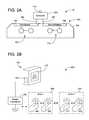
- FIG. 2Ais a schematic side-view of lighting fixture system 10 shown in FIG. 1 , according to an exemplary embodiment
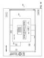
- FIG. 2Bis a diagram of a facility lighting system 200 for use with lighting fixture system 10 , according to an exemplary embodiment
- FIG. 3is a block diagram of controller 300 shown in FIGS. 1-2B , according to an exemplary embodiment
- FIG. 4is a block diagram of a control computer for a facility lighting system such as that shown in FIG. 2 , according to an exemplary embodiment
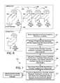
- FIG. 5Ais flow chart of a control process for controller 300 , according to an exemplary embodiment
- FIG. 6is a diagram of an exemplary control system and related control activity, according to an exemplary embodiment
- FIG. 7is a flow chart of a process for controlling multiple lighting fixtures in a zone based on sensor input, according to an exemplary embodiment.
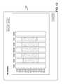
- FIGS. 8-22are illustrations of graphical user interface screens that may be caused to be displayed by control computer 202 shown in previous Figures for allowing user control of the lighting systems described herein, according to an exemplary embodiment.
- a controller local to a lighting fixtureis configured to intelligently utilize information available to the controller.
- the controllermay conduct its own control decisions based on, for example, input from a motion sensor or ambient lighting sensor local to the controller.
- the controllermay also include communications electronics for receiving “on/off” or other commands from a remote source (e.g., a network of lighting fixtures, a master controller, etc.). Regardless of the source for control decisions of the controller, the controller is configured to log usage information for the lighting fixture in memory local to the controller.
- the controllerincludes communications electronics for communicating the logged information to other devices.
- the logged usage informationmay be used by other devices in the execution of a system-wide control scheme, in the execution of control algorithms relating particularly to the lighting fixture and controller that logged the information, or otherwise.
- the controller local to the lighting fixturecan also use its own logged usage information during its local control decisions.
- the controllers described hereincan also relate to or be configured to control the electricity provided to devices other than lights.
- the controllers provided to lighting fixtures distributed around a spacecan advantageously be used to create a “grid” or wireless infrastructure in a facility that can be used to carry data communications from control systems and user interfaces to wireless relays located remotely from the control systems.
- Lighting fixture system 10includes a lighting fixture 100 and a controller 300 .
- Controller 300is connected to lighting fixture 100 via wire 14 .
- Controller 300is configured to control the switching between different states of lighting fixture 100 (e.g., all lamps on, all lamps off, some lamps on, etc.).
- controller 300is further configured to log usage information for lighting fixture 100 in a memory device local to controller 300 .
- Controller 300may further be configured to use the logged usage information to affect control logic of controller 300 .
- Controller 300may also or alternatively be configured to provide the logged usage information to another device for processing, storage, or display.
- lighting fixture 100is shown to include a housing 102 (e.g., frame, fixture pan, etc.) within which fluorescent lamps 12 are housed. While various Figures of the present application, including FIG. 1 , illustrate lighting fixtures for fluorescent lamps, it should be noted that embodiments of the present application may be utilized with any type of lighting fixture and/or lamps. Further, while housing 102 is shown as being fully enclosed (e.g., having a door and window covering the underside of the fixture), it should be noted that any variety of lighting fixture shapes, styles, or types may be utilized with embodiments of the present application. Further, while controller 300 is shown as having a housing that is exterior to housing 102 of lighting fixture 100 , it should be appreciated that controller 300 may be physically integrated with housing 102 .
- housing 102e.g., frame, fixture pan, etc.
- controller 300may be housed within, on top of, or otherwise secured to housing 102 .
- controller 300(including its housing) may be coupled directly to housing 102 .
- controller 300 's housingmay be latched, bolted, clipped, or otherwise coupled to the interior or exterior of housing 102 .
- Controller 300 's housingmay generally be shaped as a rectangle (as shown), may include one or more non-right angles or curves, or otherwise configured.
- controller 300 's housingis made of plastic and housing 102 for the lighting fixture 100 is made from metal. In other embodiments, other suitable materials may be used.
- Lighting fixture 100is shown to include two lamp sets 108 , 110 with two fluorescent lamps forming each lamp set. Each lamp set 108 , 110 may further include one or any number of additional fluorescent lamps. Lighting fixture 100 is further shown to include first ballast 104 and second ballast 106 .
- first ballast 104 and second ballast 106are examples of ballasts.
- Controller 300is shown as wired to ballasts 104 , 106 via wires 280 , 281 (which may be contained within one cable or wire loom such as shown in FIG. 14 ).
- Facility lighting system 200for use with lighting fixture system 10 including controller 300 and lighting fixture 100 is shown, according to an exemplary embodiment.
- Facility lighting system 200is shown to include control computer 202 that is configured to conduct or coordinate control activities relative to multiple lighting fixture controllers such as controller 300 .
- Control computer 202is preferably configured to provide a graphical user interface to a local or remote electronic display screen for allowing a user to adjust control parameters, turn lighting fixtures on or off, or to otherwise affect the operation of lighting fixtures in a facility.
- control computer 202is further shown to include touch screen display 210 for displaying such a graphical user interface and for allowing user interaction (e.g., input and output) with control computer 202 .
- touch screen display 210for displaying such a graphical user interface and for allowing user interaction (e.g., input and output) with control computer 202 .
- Various exemplary graphical user interfaces for display on touch screen display 210 and control activities associated therewithare described in subsequent paragraphs and with reference to subsequent Figures of the present application. It should be noted that while control computer 202 is shown in FIG.
- the user interfacesare intended to provide an easily configurable lighting and/or energy management system for a facility.
- the user interfacesare intended to allow even untrained users to reconfigure or reset a lighting system using relatively few clicks.
- the user interfacesdo not require a keyboard for entering values.
- users other than building managersmay be able to setup, interact with, or reconfigure the system using the provided user interfaces.
- each controller associated with a lighting fixtureincludes circuitry configured to provide a variety of “smart” or “intelligent features” that are either independent of control computer 202 or operate in concert with control computer 202 .
- a detailed block diagram of such a controlleris shown in FIG. 3 .
- Controller 300is generally configured to include circuitry configured with an algorithm to control on/off cycling of connected lighting fixtures, an algorithm to log usage information for the lighting fixture, an algorithm configured to prevent premature restrikes to limit wear on the lamps and ballast, and an algorithm configured to allow controller 300 to send and receive commands or information from other peer devices independently from a master controller or master transceiver.
- Controller 300is shown to include power relays 302 configured to controllably switch on or off high voltage power outputs that may be provided to first ballast 104 and second ballast 106 via wires 280 , 281 . It should be noted that in other exemplary embodiments, power relays 302 may be configured to provide a low voltage control signal, optical signal, or otherwise to the lighting fixture which may cause one or more ballasts, lamps, and/or circuits of the fluorescent lighting fixture that the controller serves to turn on and off. While power relays 302 are configured to provide high voltage power outputs to ballasts 104 , 106 , it should be appreciated that controller 300 may include a port, terminal, receiver, or other input for receiving power from a high voltage power source.
- power for circuitry of controller 300may be received from a power source provided to the lighting fixtures or from another source.
- appropriate power supply circuitrye.g., filtering circuitry, stabilizing circuitry, etc.
- controller 300may be included with controller 300 to provide power to the components of controller 300 (e.g., relays 302 ).
- wireless controller 305Upon recognizing the “off” command, wireless controller 305 provides an appropriate control signal to control circuit 304 which causes control circuit 304 to switch one or more of power relays 302 off. Similarly, when sensor circuit 310 including sensor 112 experiences an environmental condition, logic module 314 may determine whether or not the controller and control circuit 304 should change “on/off” states.
- logic module 314may determine that control circuit 304 should change states such that power relays 302 are “off” Conversely, if a low ambient lighting level is detected by sensor 112 , logic module 314 may cause control circuit 304 to turn power relays 302 “on.”
- Other control decisions, logic and activities provided by controller 300 and the components thereofare described below and with reference to other Figures.
- the logged usage informationincludes an event identifier (e.g., “on”, “off”, cause for the state change, etc.) and a timestamp (e.g., day and time) from which total usage may be derived.
- the total “on” time for the lighting fixture (or lamp set)is counted such that only an absolute number of hours that the lamp has been on (for whatever reason) has been tracked and stored as the logged usage information.
- each logic module 314may be configured to process usage information or transform usage information into other values or information.
- any such information relating to usage for the lighting fixturemay be considered logged “usage information.”
- the usage information logged by module 314is limited to on/off events or temporal aggregation of on states; in such embodiments energy savings calculations or other calculations may be completed by a control computer 202 or another remote device.
- controller 300(e.g., via wireless transceiver 306 ) is configured to transmit the logged usage information to remote devices such as control computer 202 .
- Wireless controller 305may be configured to recall the logged usage information from memory 316 at periodic intervals (e.g., every hour, once a day, twice a day, etc.) and to provide the logged usage information to wireless transceiver 306 at the periodic intervals for transmission back to control computer 202 .
- control computer 202(or another network device) transmits a request for the logged information to wireless transceiver 306 and the request is responded to by wireless controller 305 by transmitting back the logged usage information.
- a plurality of controllerssuch as controller 300 asynchronously collect usage information for their fixture and control computer 202 , via request or via periodic transmission of the information by the controllers, gathers the usage information for later use.
- Wireless controller 306may also be configured to handle situations or events such as transmission failures, reception failures, and the like. Wireless controller 306 may respond to such failures by, for example, operating according to a retransmission scheme or another transmit failure mitigation scheme. Wireless controller 306 may also control any other modulating, demodulating, coding, decoding, routing, or other activities of wireless transceiver 306 .
- controller 300 's control logice.g., controlled by logic module 314 and/or control circuit 304
- Such transmissionscan be controlled by wireless controller 306 and such control may include, for example, maintaining a token-based transmission system, synchronizing clocks of the various RF transceivers or controllers, operating under a slot-based transmission/reception protocol, or otherwise.
- control circuit 304is configured to prevent damage to lamps 108 or 110 from manual or automatic control activities.
- control circuit 304may be configured to prevent on/off cycling of lamps 108 , 110 by holding the lamps in an “on” state for a predefined period of time (e.g., thirty minutes, fifteen minutes, etc.) even after the condition that caused the lamp to turn on is no longer true.
- control circuit 304may keep the lamps on (even though the on condition expired) for a predetermined period of time so that the lamps are taken through their preferred cycle.
- control circuit 304may be configured to hold the lamp in an “off” state for a predefined period of time since the lamp was last turned off to ensure that the lamp is given time to cool or otherwise settle after the last “on” state.
- a self-diagnostic featurewould monitor the number of times that a fixture or device was instructed to turn on (or off) based upon a signal received from a sensor (e.g. motion, ambient light level, etc.). If the number of instructions to turn on (or off) exceeded a predetermined limit during a predetermined time period, the logic module 314 and/or control circuit 304 could be programmed to detect that the particular application for the fixture or device is not well-suited to control by such a sensor (e.g. not an optimum application for motion control or ambient light-based control, etc.), and would be programmed to disable such a motion or ambient light based control scheme, and report/log this action and the basis.
- a sensore.g. motion, ambient light level, etc.
- the algorithmis based on more than four instructions to turn on (or off) in a 24 hour period, and the number of instructions provided based on signals from the sensor exceeds this limit within this period, the particular sensor-based control function would be disabled, as not being optimally suited to the application and a notification would be logged and provided to a user or facility manager.
- the limit and time periodmay be any suitable number and duration intended to suit the operational characteristics of the fixture/device and the application.
- the fixture or deviceis intended to remain operational in response to other available control schemes (e.g. other sensors, time-based, user input or demand, etc.).
- This ability to learn or self-updateis intended to permit the system to adjust itself to update the sensor-based control schemes to different time periods that are more optimally suited for such a control scheme, and to avoid time periods that are less optimum for such a particular sensor-based control scheme.
- Control computer 202may be configured as the “master controller” described in U.S. application Ser. No. 12/240,805, filed Sep. 29, 2008, and incorporated herein by reference in its entirety.
- Control computer 202is generally configured to receive user inputs (e.g., via touchscreen display 210 ) and to set or change settings of lighting system 200 based on the user inputs.
- control computer 202is shown to include processing circuit 402 including memory 404 and processor 406 .
- control computer 202 and more particularly processing circuit 402are configured to run a Microsoft Windows Operating System (e.g., XP, Vista, etc.) and are configured to include a software suite configured to provide the features described herein.
- the software suitemay include a variety of modules (e.g., modules 408 - 414 ) configured to complete various activities of control computer 202 .
- Modules 408 - 414may be or include computer code, analog circuitry, one or more integrated circuits, or another collection of logic circuitry.
- processor 406may be a general purpose processor, a specific purpose processor, a programmable logic controller (PLC), a field programmable gate array, a combination thereof, or otherwise and configured to complete, cause the completion of, and/or facilitate the completion of the activities of control computer 202 described herein (e.g., as variously shown and described in and with references to FIGS. 1-22 ).
- Memory 404may be configured to store historical data received from lighting fixture controllers or other building devices, configuration information, schedule information, setting information, zone information, or other temporary or archived information.
- Memory 404may also be configured to store computer code for execution by processor 406 . When executed, such computer code (e.g., stored in memory 404 or otherwise, script code, object code, etc.) configures processing circuit 402 , processor 406 or more generally control computer 202 for the activities described herein.
- Touch screen display 210 and more particularly user interface module 408are configured to allow and facilitate user interaction (e.g., input and output) with control computer 202 .
- the display associated with control computer 202may not be a touch screen, may be separated from the casing housing the control computer, and/or may be distributed from the control computer and connected via a network connection (e.g., Internet connection, LAN connection, WAN connection, etc.).
- control computer 202may be connected to a mouse, keyboard, or any other input device or devices for providing user input to control computer 202 .
- Control computeris shown to include a communications interface 220 configured to connect to a wire associated with master transceiver 240 .
- Communications interface 220may be a proprietary circuit for communicating with master transceiver 240 via a proprietary communications protocol.
- communications interface 220may be configured to communicate with master transceiver 240 via a standard communications protocol.
- communications interface 220may include Ethernet communications electronics (e.g., an Ethernet card) and an appropriate port (e.g., an RJ45 port configured for CAT5 cabling) to which an Ethernet cable is run from control computer 202 to master transceiver 240 .
- Master transceiver 240may be as described in U.S. application Ser. Nos. 12/240,805, 12/057,217, or 11/771,317 which are each incorporated herein by reference.
- Wireless interface module 412may include drivers, control software, configuration software, or other logic configured to facilitate communications activities of control computer 202 with lighting fixture controllers. For example, wireless interface module 412 may package, address format, or otherwise prepare messages for transmission to and reception by particular controllers or zones. Wireless interface module 412 may also interpret, route, decode, or otherwise handle communications received at master transceiver 240 and communications interface 220 .
- user interface module 408may include the software and other resources for the display of FIGS. 8-22 and the handling of automatic or user inputs received at the graphical user interfaces of control computer 202 . While user interface module 408 is executing and receiving user input, user interface module 408 may interpret user input and cause various other modules, algorithms, routines, or sub-processes to be called, initiated, or otherwise affected. For example, control logic module 414 and/or a plurality of control sub-processes thereof may be called by user interface module 408 upon receiving certain user input events. User interface module 408 may also be configured to include server software (e.g., web server software, remote desktop software, etc.) configured to allow remote access to the screens shown in FIGS. 8-22 .
- server softwaree.g., web server software, remote desktop software, etc.
- User interface module 408may be configured to complete some of the control activities described herein rather than control logic module 414 . In other embodiments, user interface module 408 merely drives the graphical user interfaces and handles user input/output events while control logic module 414 controls the majority of the actual control logic.
- Control logic module 414may be the primary logic module for control computer 202 and may be the main routine that calls, for example, modules 408 , 410 , etc. Control logic module 414 may generally be configured to provide lighting control, energy savings calculations, demand/response-based control, load shedding, load submetering, HVAC control, building automation control, workstation control, advertisement control, power strip control, “sleep mode” control, or any other types of control. In an exemplary embodiment, control logic module 414 operates based off of information stored in one or more databases of control computer 202 and stored in memory 404 or another memory device in communication with control computer 202 . The database may be populated with information based on user input received at graphical user interfaces (e.g., shown in FIGS.
- control logic module 414may continuously draw on the database information to make control decisions. For example, a user may establish any number of zones, set schedules for each zone, create ambient lighting parameters for each zone or fixture, etc. This information is stored in the database, related (e.g., via a relational database scheme, XML sets for zones or fixtures, or otherwise) and recalled by control logic module 414 as control logic module 414 proceeds through its various control algorithms.
- Control logic module 414may include any number of functions or sub-processes. For example, a scheduling sub-process of control logic module 414 may check at regular intervals to determine if an event is scheduled to take place. When events are determined to take place, the scheduling sub-process or another routine of control logic module 414 may call or otherwise use another module or routine to initiate the event. For example, if the schedule indicates that a zone should be turned off at 5:00 pm, then when 5:00 pm arrives the scheduling sub-process may call a routine (e.g., of wireless interface module) that causes an “off” signal to be transmitted by master transceiver 240 . Control logic module 414 may also be configured to conduct or facilitate the completion of any other process, sub-process, or process steps conducted by control computer 202 described herein.
- a scheduling sub-process of control logic module 414may check at regular intervals to determine if an event is scheduled to take place. When events are determined to take place, the scheduling sub-process or another routine of control logic module 414 may call or otherwise use another module or
- device interface module 410facilitates the connection of one or more field devices, sensors, or other inputs not associated with master transceiver 240 .
- fieldbus interfaces 416 and 420may be configured to communicate with any number of monitored devices 418 and 422 . The communication may be according to a communications protocol which may be standard or proprietary and/or serial or parallel.
- Fieldbus interfaces 416 , 420can be or include circuit cards for connection to processing circuit 402 , jacks or terminals for physically receiving connectors from wires coupling monitored devices 418 , 422 , logic circuitry or software for translating communications between processing circuit 402 and monitored devices 418 , 422 , or otherwise.
- device interface module 410handles and interprets data input from the monitored devices and controls the output activities of fieldbus interfaces 416 , 420 to monitored devices 418 , 422 .
- Fieldbus interfaces 416 and 420 and device interface module 410may also be used in concert with user interface module 408 and control logic module 414 to provide control to the monitored devices 418 , 422 .
- monitored devices 418 , 422may be mechanical devices configured to operate a motor, one or more electronic valves, one or more workstations, machinery stations, a solenoid or valve, or otherwise. Such devices may be assigned to zones similar to the lighting fixtures described above and below or controlled independently.
- User interface module 408may allow schedules and conditions to be established for each of devices 418 , 422 so that control computer 202 may be used as a comprehensive energy management system for a facility.
- a motor that controls the movement of a spinning advertisementmay be coupled to the power output or relays of a controller very similar if not identical to controller 300 .
- This controllermay be assigned to a zone (e.g., via user interfaces at touchscreen display 210 ) and provided a schedule for turning on and off during the day.
- the electrical relays of the controllermay be coupled to other building devices such as video monitors for informational display, exterior signs, task lighting, audio systems, or other electrically operated devices.
- power monitor 450is shown as coupled to fieldbus interfaces 416 in an exemplary embodiment. However, power monitor 450 may also or alternatively be coupled to its own controller or RF transceiver 451 for communicating with master transceiver 240 . Power monitor 450 may generally be configured to couple to building power resources (e.g., building mains input, building power meter, etc.) and to receive or calculate an indication of power utilized by the building or a portion of the building. This input may be received in a variety of different ways according to varying embodiments.
- building power resourcese.g., building mains input, building power meter, etc.
- power monitor 450may include a current transformer (CT) configured to measure the current in the mains inlet to a building, may be coupled to or include a pulse monitor, may be configured to monitor voltage, or may monitor power in other ways.
- CTcurrent transformer
- Power monitor 450is intended to provide “real time” or “near real time” monitoring of power and to provide the result of such monitoring to control computer 202 for use or reporting.
- control logic module 414may be configured to include logic that sheds loads (e.g., sends off signals to lighting fixtures via a lighting fixture controller network, sends off signals to monitored devices 418 , 422 , adjusts ambient light setpoints, adjusts schedules, shuts lights off according to a priority tier, etc.) to maintain a setpoint power meter level or threshold.
- control logic module 414may store or receive pricing information from a utility and shed loads if the metered power usage multiplied by the pricing rate is greater than certain absolute thresholds or tiered thresholds.
- control logic module 406may be configured to change the ambient light setpoints for the lighting fixtures in the building until daily energy cost is expected to fall beneath $500.
- user interface module 408is configured to cause a screen to be displayed that allows a user to associate different zones or lighting fixtures with different demand/response priority levels. Accordingly, a utility provider or internal calculation determines that a load should be shed, control logic module 414 will check the zone or lighting fixture database to shed loads of the lowest priority first while leaving higher priority loads unaffected.
- Process 500is shown to include receiving a signal from an environment sensor at control circuitry (e.g., sensor circuit 310 , control circuit 304 ) (step 501 ).
- Process 500further includes using the control circuitry to determine whether the lighting fixture should change states (step 502 ).
- Controller 300is configured to log usage information for the lighting fixture when states are changed (step 503 ). As mentioned above, logging usage information may include tracking an aggregate “time on” for each ballast or lamp set of the lighting fixture.
- controller 300 or control computer 202may allow a user to “reset” logged usage information in whole or in part so that the logged usage information may be used for lamp maintenance prediction.
- control logic module 414 of the control computermay examine the received usage information to determine whether a lamp or lamp set is near the end of its normal usage life. If a lamp or lamp set is determined to be at the end of its normal usage life, control logic module 414 may command user interface module 408 to cause a warning or other message or report to be displayed via touchscreen display 210 .
- process 500is further shown to include transmitting the logged usage information (step 504 ).
- Controller 300may be configured to transmit the logged usage information back to control computer 202 for processing, archival, or action.
- the logged usage informationincludes an indication of an event (e.g., a message indicating “I have turned off due to adequate ambient light”)
- controller 300may transmit the logged usage information for use by other controllers in its zone.
- Controller 300may also be configured to receive a command from a remote device (e.g., control computer 200 , another lighting fixture controller, a wireless router, etc.) (step 505 ) and to cause one or more lamps (e.g., lamp sets, ballasts, etc.) of the lighting fixture to turn on or off based on the received commands (step 506 ).
- a remote devicee.g., control computer 200 , another lighting fixture controller, a wireless router, etc.
- lampse.g., lamp sets, ballasts, etc.
- Process 510is shown to include receiving a submetered power level (e.g., in the form of a data message) from a power monitoring device (e.g., power monitor 450 ) or devices (e.g., distributed metering devices) (step 511 ).
- Process 500may further include receiving logged usage information from the lighting network (e.g., usage information logged as described above with respect to controller 300 or process 500 ) (step 512 ) and calculating the power level or power usage for the lighting network using the received usage information (step 513 ).
- Control computer 202may be configured to output the calculated or received power level or usage information (e.g., via a display, via a website, via a report) or control computer 202 may be configured to take one or more actions based on the usage.
- step 508may include comparing the metered or calculated power level to a threshold, tiers of a tier-based system, pricing structure, budget information, or requested values from the power supplier (step 514 ). Based on the comparison, control computer 202 may determine and execute a control strategy for shedding loads (step 515 ).
- Various control strategies for shedding loads or demand-based control strategiesare described in U.S. application Ser. No. 12/240,805, the entirety of which is incorporated by reference.
- lighting fixtures(or more particularly controllers for lighting fixtures) can be grouped into zones. Rather than reporting motion, ambient light, or other sensed conditions back to master controller 240 for processing or action, controllers such as controller 300 may be configured to broadcast commands or conditions to other RF transceivers coupled to other controllers in the same zone. For example, in FIG. 6 , lighting zone I includes four controllers.
- logic module 314 and/or control circuit 304causes wireless transceiver 306 to transmit an indication that motion was detected by the sensor.
- control circuits of the controllers receiving the indicationcan decide whether or not to act upon the indication of motion.
- the RF signals including an indication of motionmay also include a zone identifier that receiving controllers can use to determine if the signal originated from their zone or another zone.
- controller 300may address messages to particular controllers (e.g., the addresses of neighbors or the addresses of other controllers in the zone).
- Logic module 314may further be configured to cause the radio frequency transceiver to transmit commands to other radio frequency transceivers coupled to other fluorescent lighting fixtures.
- logic module 314 and/or control circuit 304may be configured to interpret a signal received at the radio frequency transceiver as indicating that motion was detected by another device in the zone.
- Controller 604is illustrated to be configured as such a relay device.
- controller 604receives broadcast 600 indicating motion from controller 300
- controller 604relays broadcast 600 via transmission 602 to other zone devices (e.g., controller 606 ). This way, an event such as motion can be propagated to each of the lighting fixtures in a zone without network traffic to main controller 240 and/or without necessitating direct control of the lighting fixtures by main controller 240 .
- This activitymay be configurable (e.g., via a GUI provided by control computer 202 ) so that only some controllers are relays, all controllers are relays, or so that no controllers are relays and only devices within range of the detecting controller act on its broadcasts.
- the relay or rebroadcastcan be address-based or more similar to a true broadcast.
- the controller serving as a relaymay know the addresses of certain network controllers to which to transmit the relayed information.
- the broadcastmay be general and not addressed to any particular controller, controllers, or zone.
- each controllermay be configured to store a lighting zone value in memory (e.g., memory 316 ). This value may be used, for example, to determine whether another device sending a command is associated with the lighting zone value stored in memory.
- controller 271may include a lighting zone value of “II” in memory and controller 300 may include data representative of controller 300 's lighting zone value (e.g., “I”) with its transmission indicating that motion was detected.
- controller 271When controller 271 receives the lighting zone value, controller 271 (e.g., a control circuit or logic circuit thereof) may compare “I” and “II” and make a determination that controller 271 will not act on the received indication of motion (i.e., controller 271 leaves its relays off while all of the controllers in zone I switch their relays on.
- Process 700is shown to include receiving signals from a sensor (e.g., sensor 212 ) coupled to a first controller for a first zone (step 702 ). Once received, circuitry of the first controller can determine whether the received signals represent an event that should be acted upon (e.g., by changing lighting states, etc.) in the first zone (step 704 ). Process 700 is further shown to include using circuitry of the first controller to transmit a command and/or an indication of the event with a first zone identifier (step 706 ). The transmission is received by a controller in a second zone.
- a sensore.g., sensor 212
- circuitry of the first controllercan determine whether the received signals represent an event that should be acted upon (e.g., by changing lighting states, etc.) in the first zone (step 704 ).
- Process 700is further shown to include using circuitry of the first controller to transmit a command and/or an indication of the event with a first zone identifier (step 706 ). The transmission is received by a
- Circuitry of the controller in the second zonedetermines that the transmission is for another zone and does not act on the received transmission (step 708 ).
- the transmissionmay also be received by a second controller for the first zone (step 710 ).
- Circuitry of the second controller for the first zoneinspects the received transmission and acts on the information of the transmission when the controller discovers that its stored zone identifier matches the received zone identifier (step 712 ).
- the second controller for the first zonemay also be configured as a relay node and to retransmit the received command or indication to other first zone controllers (e.g., controller 606 ).
- GUIsgraphical user interfaces
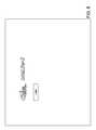
- FIG. 8is an illustration of a login screen that may be provided to a display screen such as touchscreen display 210 by control computer 202 , according to an exemplary embodiment. It should be appreciated that trademarks, markings, or information other than Orion and InteLite II may be shown on the login screen. By clicking on the login button, a user may be prompted for a password, username, or other credentials that the system checks to log the user into control computer 202 .
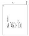
- FIG. 9is an illustration of a main menu screen 900 that may be provided to a display by control computer 202 , according to an exemplary embodiment.
- control computer 202causes the screen to display buttons (which could be other UI elements such as hyperlinks) for launching a lighting layout (button 902 ) mode, launching an emissions offset calculator (button 904 ), and entering a setting mode (button 906 ).
- Main menu screen 900can also include an override utility 910 including, for example, an all rights on button 911 and an all lights off button 912 . Lighting layout modes or features are described in subsequent Figures (e.g., FIG. 10 ).
- the emissions offset calculator launched by button 904may provide a screen or report that compares the power usage of the current lighting system compared to conventional or historical lighting systems.
- the power usage of the current lighting systemmay be calculated based on usage information from lighting fixture controllers or based on power meter readings from, for example, power monitor 450 shown in FIG. 4 .
- the emissions offset calculator screencan show the results of aggregations or calculations that equate the power savings to cost savings, an equivalent amount of carbon credits, an equivalent emissions value, or another environmental values that quantifies the reduced financial and/or environmental impact due to the improved lighting system and/or control strategies at work in a facility when one or more of the features contained herein are implemented.
- FIG. 10is an illustration of a lighting layout or lighting zones screen 1000 that may be provided to a display by control computer 202 when button 902 of FIG. 9 is selected, according to an exemplary embodiment.
- Screen 1000is shown to include a map (e.g., grid, layout, floor plan) including boundaries defining a plurality of lighting zones (labeled in screen 1000 as L Zone 10, L Zone 20, L Zone 30, and L Zone 40).
- each zoneis shown to include a zone identifier 1002 and a lighting fixture icon 1004 .
- the lighting fixture icon 1004can be located at a coordinate on the map corresponding to the actual geolocation for the lighting fixture.
- FIG. 11is an illustration of lighting zones screen 1000 from FIG. 10 , but including a lighting zone dialog box 1102 that may be provided to a display by control computer 202 , according to an exemplary embodiment.
- Dialog box 1102is displayed to a user when, for example, lighting fixture icon 1004 associated with a particular lighting zone is clicked or otherwise selected.
- Dialog box 1102includes a current status indicator 1104 as well as controls 1106 , 1108 , and 1110 for changing the status of the lighting fixture.
- current status indicator 1104is illustrated to indicate that zone 10's lighting fixture is “all on.” On a computer screen, this may be indicated by yellow lamps in the illustration of the lighting fixture rather than black lamps.
- “on”may be indicated by a glow on top of the lighting fixture, a glow coming from behind the lighting fixture, an “ON” icon, text indicating the status (e.g., similar to that shown in controls 1106 - 1110 , etc.), or otherwise.
- the usercan click control 1106 or 1108 .
- control computer 202may recognize the selection and cause a command for the appropriate lighting fixture controller (e.g., controller 300 ) to be broadcast from master transceiver 240 via RF communications. Making such a selection may place the lighting fixture into a manual mode of operation permanently or temporarily.
- control computer 202tracks and controls the mode of operation for each lighting fixture and/or each zone. If a zone is configured for other than manual operation and dialog box 1102 is used to change the state of a lighting fixture in the zone, the lighting fixture may maintain the user selected state for some period of time before returning to the state commanded by the mode of operation programmed to control the zone. For example, a zone may be configured to turn on or off according to a schedule which may be set or adjusted by clicking on button 1114 . Control computer 202 may be configured to turn on or off based on ambient light sensed by, e.g., sensor 112 shown in previous Figures. Ambient lighting settings for the zone may be set or adjusted by clicking button 1116 on dialog box 1102 .
- FIG. 13is an illustration of a lighting zone ambient light setting screen 1300 that may be provided to a display by control computer 202 , according to an exemplary embodiment.
- Screen 1300may be displayed, for example, when button 1116 of dialog box 1102 is clicked.
- Screen 1300is shown to include three slider controls (although in various exemplary embodiments, other types of controls may be used for level setting/selection) 1302 , 1304 , and 1308 .
- Slider 1302may be used to set an ambient lighting level for a first ballast (e.g., ballast 104 shown in FIG. 2A ) of lighting fixtures in a zone
- slider 1304may be used to set an ambient lighting level for a second ballast (e.g., ballast 106 shown in FIG.
- a first ballaste.g., ballast 104 shown in FIG. 2A
- second ballaste.g., ballast 106 shown in FIG.
- Control computer 202may be configured to turn a ballast on or off depending on the current ambient reading for a fixture or zone relative to the set points selected via sliders 1302 , 1304 .
- FIG. 13illustrates that for the zone affected by screen 1300 , ballast 1 requires a sixty percent or greater ambient light reading before control computer 202 will cause ballast 1 to turn off.
- ballast 2only requires a fifteen percent or greater ambient light reading before control computer 202 will cause ballast 2 to turn off. Accordingly, three different levels of lighting (and energy use) may be set up via sliders 1302 , 1304 .
- Dead band slider 1308may allow a user to adjust the responsiveness of the system by creating one or more dead band percentage points that a system may be able to stay within before causing the system to change states. That is, on a cloudy day where the ambient lighting level is fluctuating around fifteen percent, a dead band percentage of a few points may prevent the lighting fixtures from being commanded to oscillate.
- a usermay track current ambient reading levels via display element 1306 and use the current level to assist in slider 1302 , 1304 selections.
- screen 1300for any given building zone, a user may be able to find an acceptable balance of artificial and natural light that will result in significant energy cost savings relative to an “all on” or ambient light independent control system while meeting illumination requirements for a space (e.g., foot-candle requirements).
- Screen 1300may also advantageously provide a user with the ability to provide a greater number of light intensity “steps” within a building which may advantageously improve occupant comfort.
- These settingsmay be compiled by controller 202 for zones, lighting fixtures within zones, or individual lighting fixtures and transmitted to the controllers for incorporation into the controllers' memory and/or control algorithms.
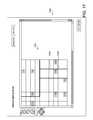
- FIG. 14is an illustration of a lighting zones detail screen 1400 that may be provided to a display by control computer 202 , according to an exemplary embodiment.
- Lighting zones detail screenmay be obtained by “zooming in” using controls 1008 .
- a usermay be provided an icon such as icon 1402 for each lighting fixture (rather than a single fixture icon representing the lights within a zone, as may be provided when “zoomed out” in some embodiments).
- an alpha-numerical identifier (or other identifier) for each lighting controllermay be shown with each lighting fixture icon so that a manager of the building space can better identify each lighting fixture in the building or zone.
- zone 1420is shown to include at least three different lighting fixture controllers indicated by three different icons.
- Dialog box 1502is shown to identify the device and to include similar manual control options (e.g., all off, half on, all on) as shown above when controlling the entire zone.
- Button 1504is shown as a “Confirm Status” button that, when pressed, causes control computer 202 to change the state of the particular device relating to dialog box 1502 . Using this feature, a building manager can confirm that they are changing settings or otherwise correctly identifying the correct device.
- FIG. 16is an illustration of an application settings screen 1600 that may be provided to a display by control computer 202 , according to an exemplary embodiment.
- Screen 1600is shown to include a default schedule button 1602 , a default ambient light setting button 1604 , a facility setting button 1606 , a rezone layout button 1608 , and a lighting zone setting button 1610 .
- Default schedule button 1602may cause a screen to be displayed that is similar to screen 1200 shown in FIG. 12 . Entries made to the default schedule may serve as the base for zone or fixture specific edits.
- Default ambient light setting button 1604may cause a screen to be displayed that is similar to screen 1300 shown in FIG.
- the screen triggered by default ambient light setting button 1604may be applicable for all zones controlled by control computer 202 .
- Facility setting button 1606may be used to set any number of global variables that may affect the entire facility (e.g., whether to respond to demand-based control requests received from power providers, how frequently to poll controllers for logged usage information, etc.).
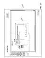
- FIG. 17is an illustration of a change settings screen 1700 that may be provided to a display by control computer 202 , according to an exemplary embodiment.
- Screen 1700may be shown to a user when button 1608 is clicked.
- Screen 1700may generally be used to change zone boundaries, to move lighting fixture icons from zone to zone, to remove lighting fixtures from a zone, or otherwise.
- Zone boundariesmay be edited by, for example, dragging boundaries such as boundary 1702 on a displayed grid.
- Lighting fixturesmay be moved by, for example, clicking and dragging a lighting fixture.
- a dialog boxmay be used to reassign a lighting fixture to a different zone when a lighting fixture icon (e.g., icon 1704 ) is clicked or otherwise selected.
- a lighting fixture icone.g., icon 1704
- device 17958 associated with icon 1704is being reassigned to lighting zone 30 (i.e., the L Zone ID stored in device 17958 will change to 30 once “Save Settings” is pressed).
- FIG. 19is an illustration of a lighting zone setting screen 1900 may be provided to a display by control computer 202 , according to an exemplary embodiment.
- a zone for changing the settings ofe.g., by clicking an the lighting fixture icon associated with the zone, by clicking the zone title, etc.
- screen 2000 shown in FIG. 20may be displayed.
- a userhas selected L Zone 30 as the zone to edit.
- the identifier for the zonei.e., L Zone Name
- the identifier for the zonemay be changed via text box 2004
- the default schedule for the zonemay be changed via schedule button 2006
- the ambient lighting settings for the zonemay be changed via button 2008
- an ambient sensor idmay be set via box 2010 .
- Changes to the lighting zonemay be saved via button 2012 . Whether the zone is generally in automatic mode or manual mode may be changed via button 2002 .
- only one ambient sensormay be used to provide ambient light readings to an entire zone. In such instances, an entire zone may be assigned to an identifier of the chosen ambient sensor. This assignment or relationship information may be propagated out to the individual controllers and/or stored in a database of memory 404 and acted on by control computer 202 .
- associating a sensor with such a zonewill cause control computer 202 to communicate to the controller for the sensor that the sensor readings should be communicated back to the master controller rather than merely acted upon locally (e.g., controller to controller).
- control computer 202receives sensor readings from a zone sensor, control computer (e.g., the control logic module thereof) sends commands appropriate for the sensor readings to the other devices.
- buttonsmay be any clickable, selectable, or otherwise interactive controls for facilitating the user interface features described.
- audioe.g., via speakers integrated with control computer 202 , via an external audio system coupled to control computer 202 , etc.
- audiomay be used for prompting the user for input and/or for receiving input from a user (e.g., via a microphone and voice recognition circuit/module).
- a usere.g., via a microphone and voice recognition circuit/module.
- other user input mechanisms of the past, present or futuremay be provided to the systems described above to provide the features discussed throughout the present application or with particular reference to FIGS. 8-22 .
- the present disclosurecontemplates methods, systems and program products on any machine-readable media for accomplishing various operations.
- the embodiments of the present disclosuremay be implemented using existing computer processors, or by a special purpose computer processor for an appropriate system, incorporated for this or another purpose, or by a hardwired system.
- Embodiments within the scope of the present disclosureinclude program products comprising machine-readable media for carrying or having machine-executable instructions or data structures stored thereon.
- Such machine-readable mediacan be any available media that can be accessed by a general purpose or special purpose computer or other machine with a processor.
- machine-readable mediacan comprise RAM, ROM, EPROM, EEPROM, CD-ROM or other optical disk storage, magnetic disk storage or other magnetic storage devices, or any other medium which can be used to carry or store desired program code in the form of machine-executable instructions or data structures and which can be accessed by a general purpose or special purpose computer or other machine with a processor.
- a network or another communications connectioneither hardwired, wireless, or a combination of hardwired or wireless
- any such connectionis properly termed a machine-readable medium.
- Machine-executable instructionsinclude, for example, instructions and data which cause a general purpose computer, special purpose computer, or special purpose processing machines to perform a certain function or group of functions.
Landscapes
- Engineering & Computer Science (AREA)
- Computer Networks & Wireless Communication (AREA)
- Circuit Arrangement For Electric Light Sources In General (AREA)
Abstract
Description
Claims (20)
Priority Applications (4)
| Application Number | Priority Date | Filing Date | Title |
|---|---|---|---|
| US13/902,449US8779340B2 (en) | 2007-06-29 | 2013-05-24 | Lighting fixture control systems and methods |
| US14/330,231US10098213B2 (en) | 2007-06-29 | 2014-07-14 | Lighting fixture control systems and methods |
| US16/154,322US10694594B2 (en) | 2007-06-29 | 2018-10-08 | Lighting fixture control systems and methods |
| US16/908,213US11026302B2 (en) | 2007-06-29 | 2020-06-22 | Outdoor lighting fixtures control systems and methods |
Applications Claiming Priority (5)
| Application Number | Priority Date | Filing Date | Title |
|---|---|---|---|
| US11/771,317US7638743B2 (en) | 2007-06-29 | 2007-06-29 | Method and system for controlling a lighting system |
| US12/057,217US8406937B2 (en) | 2008-03-27 | 2008-03-27 | System and method for reducing peak and off-peak electricity demand by monitoring, controlling and metering high intensity fluorescent lighting in a facility |
| US12/240,805US8344665B2 (en) | 2008-03-27 | 2008-09-29 | System and method for controlling lighting |
| US12/550,270US8450670B2 (en) | 2007-06-29 | 2009-08-28 | Lighting fixture control systems and methods |
| US13/902,449US8779340B2 (en) | 2007-06-29 | 2013-05-24 | Lighting fixture control systems and methods |
Related Parent Applications (1)
| Application Number | Title | Priority Date | Filing Date |
|---|---|---|---|
| US12/550,270ContinuationUS8450670B2 (en) | 2007-05-03 | 2009-08-28 | Lighting fixture control systems and methods |
Related Child Applications (1)
| Application Number | Title | Priority Date | Filing Date |
|---|---|---|---|
| US14/330,231ContinuationUS10098213B2 (en) | 2007-06-29 | 2014-07-14 | Lighting fixture control systems and methods |
Publications (2)
| Publication Number | Publication Date |
|---|---|
| US20130257292A1 US20130257292A1 (en) | 2013-10-03 |
| US8779340B2true US8779340B2 (en) | 2014-07-15 |
Family
ID=41430535
Family Applications (5)
| Application Number | Title | Priority Date | Filing Date |
|---|---|---|---|
| US12/550,270Expired - Fee RelatedUS8450670B2 (en) | 2007-05-03 | 2009-08-28 | Lighting fixture control systems and methods |
| US13/902,449Expired - Fee RelatedUS8779340B2 (en) | 2007-06-29 | 2013-05-24 | Lighting fixture control systems and methods |
| US14/330,231Active2029-07-27US10098213B2 (en) | 2007-06-29 | 2014-07-14 | Lighting fixture control systems and methods |
| US16/154,322Expired - Fee RelatedUS10694594B2 (en) | 2007-06-29 | 2018-10-08 | Lighting fixture control systems and methods |
| US16/908,213Expired - Fee RelatedUS11026302B2 (en) | 2007-06-29 | 2020-06-22 | Outdoor lighting fixtures control systems and methods |
Family Applications Before (1)
| Application Number | Title | Priority Date | Filing Date |
|---|---|---|---|
| US12/550,270Expired - Fee RelatedUS8450670B2 (en) | 2007-05-03 | 2009-08-28 | Lighting fixture control systems and methods |
Family Applications After (3)
| Application Number | Title | Priority Date | Filing Date |
|---|---|---|---|
| US14/330,231Active2029-07-27US10098213B2 (en) | 2007-06-29 | 2014-07-14 | Lighting fixture control systems and methods |
| US16/154,322Expired - Fee RelatedUS10694594B2 (en) | 2007-06-29 | 2018-10-08 | Lighting fixture control systems and methods |
| US16/908,213Expired - Fee RelatedUS11026302B2 (en) | 2007-06-29 | 2020-06-22 | Outdoor lighting fixtures control systems and methods |
Country Status (1)
| Country | Link |
|---|---|
| US (5) | US8450670B2 (en) |
Cited By (33)
| Publication number | Priority date | Publication date | Assignee | Title |
|---|---|---|---|---|
| US9125261B2 (en) | 2008-11-17 | 2015-09-01 | Express Imaging Systems, Llc | Electronic control to regulate power for solid-state lighting and methods thereof |
| US9131552B2 (en) | 2012-07-25 | 2015-09-08 | Express Imaging Systems, Llc | Apparatus and method of operating a luminaire |
| US9185777B2 (en) | 2014-01-30 | 2015-11-10 | Express Imaging Systems, Llc | Ambient light control in solid state lamps and luminaires |
| US9204523B2 (en) | 2012-05-02 | 2015-12-01 | Express Imaging Systems, Llc | Remotely adjustable solid-state lamp |
| US9210751B2 (en) | 2012-05-01 | 2015-12-08 | Express Imaging Systems, Llc | Solid state lighting, drive circuit and method of driving same |
| US9288873B2 (en) | 2013-02-13 | 2016-03-15 | Express Imaging Systems, Llc | Systems, methods, and apparatuses for using a high current switching device as a logic level sensor |
| US9301365B2 (en) | 2012-11-07 | 2016-03-29 | Express Imaging Systems, Llc | Luminaire with switch-mode converter power monitoring |
| US9312451B2 (en) | 2011-09-14 | 2016-04-12 | Express Imaging Systems, Llc | Apparatus, method to enhance color contrast in phosphor-based solid state lights |
| US9360198B2 (en) | 2011-12-06 | 2016-06-07 | Express Imaging Systems, Llc | Adjustable output solid-state lighting device |
| US9414449B2 (en) | 2013-11-18 | 2016-08-09 | Express Imaging Systems, Llc | High efficiency power controller for luminaire |
| US9462662B1 (en) | 2015-03-24 | 2016-10-04 | Express Imaging Systems, Llc | Low power photocontrol for luminaire |
| US9466443B2 (en) | 2013-07-24 | 2016-10-11 | Express Imaging Systems, Llc | Photocontrol for luminaire consumes very low power |
| US9478111B2 (en) | 2009-05-20 | 2016-10-25 | Express Imaging Systems, Llc | Long-range motion detection for illumination control |
| US9497393B2 (en) | 2012-03-02 | 2016-11-15 | Express Imaging Systems, Llc | Systems and methods that employ object recognition |
| US9538612B1 (en) | 2015-09-03 | 2017-01-03 | Express Imaging Systems, Llc | Low power photocontrol for luminaire |
| US9693433B2 (en) | 2012-09-05 | 2017-06-27 | Express Imaging Systems, Llc | Apparatus and method for schedule based operation of a luminaire |
| US9713228B2 (en) | 2011-04-12 | 2017-07-18 | Express Imaging Systems, Llc | Apparatus and method of energy efficient illumination using received signals |
| US9924582B2 (en) | 2016-04-26 | 2018-03-20 | Express Imaging Systems, Llc | Luminaire dimming module uses 3 contact NEMA photocontrol socket |
| US9951933B2 (en) | 2009-09-04 | 2018-04-24 | Orion Energy Systems, Inc. | Outdoor lighting fixtures and related systems and methods |
| US9961731B2 (en) | 2015-12-08 | 2018-05-01 | Express Imaging Systems, Llc | Luminaire with transmissive filter and adjustable illumination pattern |
| US9985429B2 (en) | 2016-09-21 | 2018-05-29 | Express Imaging Systems, Llc | Inrush current limiter circuit |
| US10187557B2 (en) | 2007-06-29 | 2019-01-22 | Orion Energy Systems, Inc. | Outdoor lighting fixture and camera systems |
| US10206265B2 (en) | 2007-06-29 | 2019-02-12 | Orion Energy Systems, Inc. | Outdoor lighting fixtures control systems and methods |
| US10230296B2 (en) | 2016-09-21 | 2019-03-12 | Express Imaging Systems, Llc | Output ripple reduction for power converters |
| US10334704B2 (en) | 2008-03-27 | 2019-06-25 | Orion Energy Systems, Inc. | System and method for reducing peak and off-peak electricity demand by monitoring, controlling and metering lighting in a facility |
| US10544917B2 (en) | 2016-08-24 | 2020-01-28 | Express Imaging Systems, Llc | Shade and wavelength converter for solid state luminaires |
| US10694594B2 (en) | 2007-06-29 | 2020-06-23 | Orion Energy Systems, Inc. | Lighting fixture control systems and methods |
| US11212887B2 (en) | 2019-11-04 | 2021-12-28 | Express Imaging Systems, Llc | Light having selectively adjustable sets of solid state light sources, circuit and method of operation thereof, to provide variable output characteristics |
| US11234304B2 (en) | 2019-05-24 | 2022-01-25 | Express Imaging Systems, Llc | Photocontroller to control operation of a luminaire having a dimming line |
| US11375599B2 (en) | 2017-04-03 | 2022-06-28 | Express Imaging Systems, Llc | Systems and methods for outdoor luminaire wireless control |
| US11653436B2 (en) | 2017-04-03 | 2023-05-16 | Express Imaging Systems, Llc | Systems and methods for outdoor luminaire wireless control |
| US11765805B2 (en) | 2019-06-20 | 2023-09-19 | Express Imaging Systems, Llc | Photocontroller and/or lamp with photocontrols to control operation of lamp |
| US12439488B2 (en) | 2022-12-09 | 2025-10-07 | Express Imaging Systems, Llc | Field adjustable output for dimmable luminaires |
Families Citing this family (160)
| Publication number | Priority date | Publication date | Assignee | Title |
|---|---|---|---|---|
| US8188878B2 (en) | 2000-11-15 | 2012-05-29 | Federal Law Enforcement Development Services, Inc. | LED light communication system |
| US11208029B2 (en) | 2002-07-12 | 2021-12-28 | Yechezkal Evan Spero | Adaptive headlight system |
| US9955551B2 (en) | 2002-07-12 | 2018-04-24 | Yechezkal Evan Spero | Detector controlled illuminating system |
| US20080231464A1 (en)* | 2007-03-24 | 2008-09-25 | Lewis Mark E | Targeted switching of electrical appliances and method |
| US8344665B2 (en) | 2008-03-27 | 2013-01-01 | Orion Energy Systems, Inc. | System and method for controlling lighting |
| US8884203B2 (en) | 2007-05-03 | 2014-11-11 | Orion Energy Systems, Inc. | Lighting systems and methods for displacing energy consumption using natural lighting fixtures |
| US8376600B2 (en) | 2007-06-29 | 2013-02-19 | Orion Energy Systems, Inc. | Lighting device |
| US9414458B2 (en) | 2007-05-24 | 2016-08-09 | Federal Law Enforcement Development Services, Inc. | LED light control assembly and system |
| US9455783B2 (en) | 2013-05-06 | 2016-09-27 | Federal Law Enforcement Development Services, Inc. | Network security and variable pulse wave form with continuous communication |
| US11265082B2 (en) | 2007-05-24 | 2022-03-01 | Federal Law Enforcement Development Services, Inc. | LED light control assembly and system |
| US20080317475A1 (en) | 2007-05-24 | 2008-12-25 | Federal Law Enforcement Development Services, Inc. | Led light interior room and building communication system |
| US9100124B2 (en) | 2007-05-24 | 2015-08-04 | Federal Law Enforcement Development Services, Inc. | LED Light Fixture |
| US9258864B2 (en) | 2007-05-24 | 2016-02-09 | Federal Law Enforcement Development Services, Inc. | LED light control and management system |
| US9294198B2 (en) | 2007-05-24 | 2016-03-22 | Federal Law Enforcement Development Services, Inc. | Pulsed light communication key |
| US8445826B2 (en) | 2007-06-29 | 2013-05-21 | Orion Energy Systems, Inc. | Outdoor lighting systems and methods for wireless network communications |
| US8729446B2 (en) | 2007-06-29 | 2014-05-20 | Orion Energy Systems, Inc. | Outdoor lighting fixtures for controlling traffic lights |
| US8754589B2 (en) | 2008-04-14 | 2014-06-17 | Digtial Lumens Incorporated | Power management unit with temperature protection |
| US8138690B2 (en)* | 2008-04-14 | 2012-03-20 | Digital Lumens Incorporated | LED-based lighting methods, apparatus, and systems employing LED light bars, occupancy sensing, local state machine, and meter circuit |
| US20120235579A1 (en) | 2008-04-14 | 2012-09-20 | Digital Lumens, Incorporated | Methods, apparatus and systems for providing occupancy-based variable lighting |
| US8531134B2 (en) | 2008-04-14 | 2013-09-10 | Digital Lumens Incorporated | LED-based lighting methods, apparatus, and systems employing LED light bars, occupancy sensing, local state machine, and time-based tracking of operational modes |
| US8373362B2 (en) | 2008-04-14 | 2013-02-12 | Digital Lumens Incorporated | Methods, systems, and apparatus for commissioning an LED lighting fixture with remote reporting |
| US8823277B2 (en) | 2008-04-14 | 2014-09-02 | Digital Lumens Incorporated | Methods, systems, and apparatus for mapping a network of lighting fixtures with light module identification |
| US8339069B2 (en) | 2008-04-14 | 2012-12-25 | Digital Lumens Incorporated | Power management unit with power metering |
| US8543249B2 (en) | 2008-04-14 | 2013-09-24 | Digital Lumens Incorporated | Power management unit with modular sensor bus |
| US8866408B2 (en) | 2008-04-14 | 2014-10-21 | Digital Lumens Incorporated | Methods, apparatus, and systems for automatic power adjustment based on energy demand information |
| CA2721486A1 (en) | 2008-04-14 | 2009-10-22 | Digital Lumens Incorporated | Modular lighting systems |
| US10539311B2 (en) | 2008-04-14 | 2020-01-21 | Digital Lumens Incorporated | Sensor-based lighting methods, apparatus, and systems |
| US8610376B2 (en) | 2008-04-14 | 2013-12-17 | Digital Lumens Incorporated | LED lighting methods, apparatus, and systems including historic sensor data logging |
| US8610377B2 (en) | 2008-04-14 | 2013-12-17 | Digital Lumens, Incorporated | Methods, apparatus, and systems for prediction of lighting module performance |
| US8368321B2 (en) | 2008-04-14 | 2013-02-05 | Digital Lumens Incorporated | Power management unit with rules-based power consumption management |
| US8552664B2 (en) | 2008-04-14 | 2013-10-08 | Digital Lumens Incorporated | Power management unit with ballast interface |
| US8805550B2 (en) | 2008-04-14 | 2014-08-12 | Digital Lumens Incorporated | Power management unit with power source arbitration |
| US8841859B2 (en) | 2008-04-14 | 2014-09-23 | Digital Lumens Incorporated | LED lighting methods, apparatus, and systems including rules-based sensor data logging |
| US8364325B2 (en) | 2008-06-02 | 2013-01-29 | Adura Technologies, Inc. | Intelligence in distributed lighting control devices |
| US8275471B2 (en)* | 2009-11-06 | 2012-09-25 | Adura Technologies, Inc. | Sensor interface for wireless control |
| US20100246168A1 (en)* | 2009-03-31 | 2010-09-30 | Orion Energy Systems, Inc. | Reflector with coating for a fluorescent light fixture |
| US8890773B1 (en) | 2009-04-01 | 2014-11-18 | Federal Law Enforcement Development Services, Inc. | Visible light transceiver glasses |
| US8954170B2 (en) | 2009-04-14 | 2015-02-10 | Digital Lumens Incorporated | Power management unit with multi-input arbitration |
| US8593135B2 (en) | 2009-04-14 | 2013-11-26 | Digital Lumens Incorporated | Low-cost power measurement circuit |
| US8536802B2 (en) | 2009-04-14 | 2013-09-17 | Digital Lumens Incorporated | LED-based lighting methods, apparatus, and systems employing LED light bars, occupancy sensing, and local state machine |
| WO2010127138A2 (en) | 2009-05-01 | 2010-11-04 | Express Imaging Systems, Llc | Gas-discharge lamp replacement with passive cooling |
| US8436542B2 (en) | 2009-05-04 | 2013-05-07 | Hubbell Incorporated | Integrated lighting system and method |
| US8541950B2 (en) | 2009-05-20 | 2013-09-24 | Express Imaging Systems, Llc | Apparatus and method of energy efficient illumination |
| USD621411S1 (en) | 2009-08-28 | 2010-08-10 | Orion Energy Systems, Inc. | Graphical user interface for a display screen |
| USD621410S1 (en) | 2009-08-28 | 2010-08-10 | Orion Energy Systems, Inc. | Graphical user interface for a display screen |
| USD606698S1 (en)* | 2009-09-04 | 2009-12-22 | Orion Energy Systems, Inc. | Lighting fixture |
| USD606697S1 (en)* | 2009-09-04 | 2009-12-22 | Orion Energy Systems, Inc. | Lighting fixture |
| USD650225S1 (en) | 2009-09-14 | 2011-12-13 | Orion Energy Systems, Inc. | Guard for a lighting apparatus |
| US20110112690A1 (en)* | 2009-09-23 | 2011-05-12 | Scl Elements Inc. | Digital control manager |
| US9155167B2 (en)* | 2009-10-01 | 2015-10-06 | Ixys Intl Limited | Registering a replaceable RF-enabled fluorescent lamp starter unit to a master unit |
| US9433067B2 (en)* | 2009-10-03 | 2016-08-30 | Ixys Intl Limited | Dimming a multi-lamp fluorescent light fixture by turning off an individual lamp using a wireless fluorescent lamp starter |
| WO2011087683A1 (en)* | 2010-01-13 | 2011-07-21 | Masco Corporation | Low voltage control systems and associated methods |
| US20110185349A1 (en)* | 2010-01-28 | 2011-07-28 | Empower Electronics, Inc. | Lamp ballast configured to operate in a self-forming network |
| PL390613A1 (en)* | 2010-03-04 | 2011-09-12 | Lars Co. K. Łagutko, A. Roman, J. Belino-Studziński Spółka Jawna | The method of controlling electrical devices, in particular lighting lamps, the system of controlling electrical devices, in particular lighting lamps, the way of controlling lighting lamps and the lighting lamp |
| USD623340S1 (en) | 2010-03-26 | 2010-09-07 | Orion Energy Systems, Inc. | Reflector for a lighting fixture |
| US20110235317A1 (en)* | 2010-03-26 | 2011-09-29 | Orion Energy Systems, Inc. | Lighting device with throw forward reflector |
| US9173267B2 (en)* | 2010-04-01 | 2015-10-27 | Michael L. Picco | Modular centralized lighting control system for buildings |
| US20110270420A1 (en)* | 2010-04-09 | 2011-11-03 | Kent Tabor | Motion control enhanced radio frequency control system and method |
| US8376583B2 (en) | 2010-05-17 | 2013-02-19 | Orion Energy Systems, Inc. | Lighting system with customized intensity and profile |
| WO2012018526A1 (en) | 2010-07-26 | 2012-02-09 | Lightwaves Systems, Inc. | Improved high bandwidth data transport system for use in a smartgrid |
| EP3517839B1 (en) | 2010-11-04 | 2021-09-22 | Digital Lumens Incorporated | Method, apparatus, and system for occupancy sensing |
| US10564613B2 (en) | 2010-11-19 | 2020-02-18 | Hubbell Incorporated | Control system and method for managing wireless and wired components |
| US8355805B2 (en) | 2011-03-08 | 2013-01-15 | D. Light Design, Inc. | Systems and methods for activation and deactivation of appliances |
| US8604701B2 (en) | 2011-03-22 | 2013-12-10 | Neal R. Verfuerth | Systems and method for lighting aisles |
| USD676185S1 (en) | 2011-04-27 | 2013-02-12 | Digital Lumens, Inc. | Lighting apparatus |
| USD671251S1 (en) | 2011-04-27 | 2012-11-20 | Digital Lumens, Inc. | Lighting fixture |
| DE102011017729A1 (en)* | 2011-04-28 | 2012-10-31 | Zumtobel Lighting Gmbh | Control element for a lighting system |
| WO2012170856A1 (en)* | 2011-06-10 | 2012-12-13 | Lutron Electronics Co., Inc. | Method and apparatus for adjusting an ambient light threshold |
| WO2012172470A1 (en)* | 2011-06-13 | 2012-12-20 | Koninklijke Philips Electronics N.V. | Adaptive controlled outdoor lighting system and method of operation thereof |
| US10874003B2 (en) | 2011-07-26 | 2020-12-22 | Hunter Industries, Inc. | Systems and methods for providing power and data to devices |
| US11917740B2 (en) | 2011-07-26 | 2024-02-27 | Hunter Industries, Inc. | Systems and methods for providing power and data to devices |
| US8710770B2 (en)* | 2011-07-26 | 2014-04-29 | Hunter Industries, Inc. | Systems and methods for providing power and data to lighting devices |
| US20150237700A1 (en) | 2011-07-26 | 2015-08-20 | Hunter Industries, Inc. | Systems and methods to control color and brightness of lighting devices |
| US9609720B2 (en) | 2011-07-26 | 2017-03-28 | Hunter Industries, Inc. | Systems and methods for providing power and data to lighting devices |
| US9521725B2 (en) | 2011-07-26 | 2016-12-13 | Hunter Industries, Inc. | Systems and methods for providing power and data to lighting devices |
| US20130110424A1 (en)* | 2011-10-28 | 2013-05-02 | General Electric Company | Apparatus and method to detect power |
| CA2854784C (en) | 2011-11-03 | 2021-07-20 | Digital Lumens Incorporated | Methods, systems, and apparatus for intelligent lighting |
| GB2496623B (en)* | 2011-11-16 | 2013-11-06 | Wirefield Ltd | Transmitter receiver and wireless lighting system |
| EP2781138A4 (en) | 2011-11-18 | 2015-10-28 | Express Imaging Systems Llc | Adjustable output solid-state lamp with security features |
| KR101926014B1 (en)* | 2011-11-22 | 2018-12-07 | 삼성전자주식회사 | A method and apparatus for mamaging engergy by vitualization using grouping unit controllers |
| US9192019B2 (en) | 2011-12-07 | 2015-11-17 | Abl Ip Holding Llc | System for and method of commissioning lighting devices |
| US10600044B2 (en)* | 2011-12-20 | 2020-03-24 | Angaza Design, Inc. | Solar lighting with pay-as-you go technology |
| EP2829160B1 (en) | 2012-03-19 | 2021-04-21 | Digital Lumens Incorporated | Methods, systems, and apparatus for providing variable illumination |
| US9921591B2 (en)* | 2012-03-26 | 2018-03-20 | Siemens Schweiz Ag | System and method for HVAC interlocks |
| USD719106S1 (en)* | 2012-03-30 | 2014-12-09 | Orion Energy Systems, Inc. | Transceiver housing |
| JP2013247030A (en)* | 2012-05-28 | 2013-12-09 | Panasonic Corp | Illumination control system |
| US10219338B2 (en) | 2012-07-01 | 2019-02-26 | Cree, Inc. | Modular lighting control |
| US9872367B2 (en) | 2012-07-01 | 2018-01-16 | Cree, Inc. | Handheld device for grouping a plurality of lighting fixtures |
| US8975827B2 (en) | 2012-07-01 | 2015-03-10 | Cree, Inc. | Lighting fixture for distributed control |
| US9980350B2 (en) | 2012-07-01 | 2018-05-22 | Cree, Inc. | Removable module for a lighting fixture |
| US9717125B2 (en) | 2012-07-01 | 2017-07-25 | Cree, Inc. | Enhanced lighting fixture |
| US9572226B2 (en) | 2012-07-01 | 2017-02-14 | Cree, Inc. | Master/slave arrangement for lighting fixture modules |
| US10721808B2 (en) | 2012-07-01 | 2020-07-21 | Ideal Industries Lighting Llc | Light fixture control |
| CN102802327A (en)* | 2012-07-26 | 2012-11-28 | 鸿富锦精密工业(深圳)有限公司 | LED (light emitting diode) street lamp and remote intelligent monitoring system thereof |
| USD762674S1 (en)* | 2012-11-15 | 2016-08-02 | Lg Electronics Inc. | Display of a mobile phone with transitional graphical user interface |
| US9210759B2 (en) | 2012-11-19 | 2015-12-08 | Express Imaging Systems, Llc | Luminaire with ambient sensing and autonomous control capabilities |
| US9282596B2 (en)* | 2012-12-13 | 2016-03-08 | Power Gold LLC | Intelligent lighting system |
| US9155166B2 (en) | 2012-12-18 | 2015-10-06 | Cree, Inc. | Efficient routing tables for lighting networks |
| CN104854401B (en)* | 2012-12-18 | 2018-06-22 | 科锐 | Master/slave arrangement for lighting fixture modules |
| US9913348B2 (en) | 2012-12-19 | 2018-03-06 | Cree, Inc. | Light fixtures, systems for controlling light fixtures, and methods of controlling fixtures and methods of controlling lighting control systems |
| US20140197758A1 (en)* | 2013-01-16 | 2014-07-17 | Cree, Inc. | Power supply with interface and embedded configuration information |
| CN104956768B (en)* | 2013-01-31 | 2018-03-20 | 飞利浦灯具控股公司 | Module, method and corresponding lighting apparatus and the illuminator used during for transmitting message in the illuminator of lighting apparatus |
| CN106793377B (en) | 2013-02-20 | 2019-03-26 | 松下电器(美国)知识产权公司 | The control method and recording medium of information terminal |
| US9800428B2 (en) | 2013-02-20 | 2017-10-24 | Panasonic Intellectual Property Corporation Of America | Control method for information apparatus and computer-readable recording medium |
| WO2014128767A1 (en)* | 2013-02-20 | 2014-08-28 | パナソニック インテレクチュアル プロパティ コーポレーション オブ アメリカ | Program and method for controlling portable information terminal |
| US9967928B2 (en) | 2013-03-13 | 2018-05-08 | Cree, Inc. | Replaceable lighting fixture components |
| WO2014160096A1 (en) | 2013-03-13 | 2014-10-02 | Federal Law Enforcement Development Services, Inc. | Led light control and management system |
| US20140288861A1 (en)* | 2013-03-20 | 2014-09-25 | Xerox Corporation | Sampling methodology for measuring power consumption for a population of power-consuming devices |
| USD744669S1 (en) | 2013-04-22 | 2015-12-01 | Cree, Inc. | Module for a lighting fixture |
| JP2014217232A (en)* | 2013-04-26 | 2014-11-17 | 東芝ライテック株式会社 | Control system |
| EP2992395B1 (en) | 2013-04-30 | 2018-03-07 | Digital Lumens Incorporated | Operating light emitting diodes at low temperature |
| JP6155985B2 (en)* | 2013-08-30 | 2017-07-05 | 東芝ライテック株式会社 | LIGHTING DEVICE, LIGHTING SYSTEM, AND CONTROL METHOD |
| GB2518865B (en)* | 2013-10-03 | 2018-04-11 | Casambi Tech Oy | Intelligent lighting control |
| WO2015049412A1 (en) | 2013-10-03 | 2015-04-09 | Casambi Technologies Oy | Intelligent lighting control |
| AU2014331746A1 (en) | 2013-10-10 | 2016-05-05 | Digital Lumens Incorporated | Methods, systems, and apparatus for intelligent lighting |
| US9622321B2 (en) | 2013-10-11 | 2017-04-11 | Cree, Inc. | Systems, devices and methods for controlling one or more lights |
| US10154569B2 (en) | 2014-01-06 | 2018-12-11 | Cree, Inc. | Power over ethernet lighting fixture |
| US20150198941A1 (en) | 2014-01-15 | 2015-07-16 | John C. Pederson | Cyber Life Electronic Networking and Commerce Operating Exchange |
| WO2015153124A1 (en) | 2014-04-02 | 2015-10-08 | Angaza Design, Inc. | Solar lighting with pay-as-you-go technology |
| US10241498B1 (en)* | 2014-05-15 | 2019-03-26 | Feetz, Inc. | Customized, additive-manufactured outerwear and methods for manufacturing thereof |
| US9723680B2 (en) | 2014-05-30 | 2017-08-01 | Cree, Inc. | Digitally controlled driver for lighting fixture |
| US9549448B2 (en) | 2014-05-30 | 2017-01-17 | Cree, Inc. | Wall controller controlling CCT |
| WO2016054085A1 (en) | 2014-09-30 | 2016-04-07 | Express Imaging Systems, Llc | Centralized control of area lighting hours of illumination |
| US9445485B2 (en) | 2014-10-24 | 2016-09-13 | Express Imaging Systems, Llc | Detection and correction of faulty photo controls in outdoor luminaires |
| TW201626855A (en)* | 2015-01-07 | 2016-07-16 | Luxul Technology Inc | Light switch device with electric meter function and intelligent electric lamp control system |
| US9686477B2 (en) | 2015-02-16 | 2017-06-20 | Cree, Inc. | Lighting fixture with image sensor |
| US9456482B1 (en) | 2015-04-08 | 2016-09-27 | Cree, Inc. | Daylighting for different groups of lighting fixtures |
| US10228711B2 (en) | 2015-05-26 | 2019-03-12 | Hunter Industries, Inc. | Decoder systems and methods for irrigation control |
| US10918030B2 (en) | 2015-05-26 | 2021-02-16 | Hunter Industries, Inc. | Decoder systems and methods for irrigation control |
| CN107852801B (en) | 2015-07-06 | 2020-01-24 | 飞利浦照明控股有限公司 | Wireless Networked Lighting System and Associated Apparatus and Method |
| US20170048953A1 (en) | 2015-08-11 | 2017-02-16 | Federal Law Enforcement Development Services, Inc. | Programmable switch and system |
| US10129952B2 (en)* | 2015-09-15 | 2018-11-13 | Cooper Technologies Company | Output adjustment of a light fixture in response to environmental conditions |
| CN105677179A (en)* | 2015-12-31 | 2016-06-15 | 魅族科技(中国)有限公司 | Flashlight brightness control method and device |
| US10211660B2 (en) | 2016-02-08 | 2019-02-19 | Cree, Inc. | LED lighting device with adaptive profiles for controlling power consumption |
| JP2017208673A (en)* | 2016-05-17 | 2017-11-24 | 株式会社リコー | ELECTRIC DEVICE, ELECTRIC DEVICE CONTROL SYSTEM, ELECTRIC DEVICE CONTROL METHOD, AND PROGRAM |
| JP6709954B2 (en)* | 2016-05-19 | 2020-06-17 | パナソニックIpマネジメント株式会社 | Lighting control system |
| US9967944B2 (en) | 2016-06-22 | 2018-05-08 | Cree, Inc. | Dimming control for LED-based luminaires |
| US10595380B2 (en) | 2016-09-27 | 2020-03-17 | Ideal Industries Lighting Llc | Lighting wall control with virtual assistant |
| US10465869B2 (en) | 2017-01-30 | 2019-11-05 | Ideal Industries Lighting Llc | Skylight fixture |
| US10451229B2 (en) | 2017-01-30 | 2019-10-22 | Ideal Industries Lighting Llc | Skylight fixture |
| US10098212B2 (en) | 2017-02-14 | 2018-10-09 | Express Imaging Systems, Llc | Systems and methods for controlling outdoor luminaire wireless network using smart appliance |
| US10219360B2 (en) | 2017-04-03 | 2019-02-26 | Express Imaging Systems, Llc | Systems and methods for outdoor luminaire wireless control |
| US10568191B2 (en) | 2017-04-03 | 2020-02-18 | Express Imaging Systems, Llc | Systems and methods for outdoor luminaire wireless control |
| US9894740B1 (en)* | 2017-06-13 | 2018-02-13 | Cree, Inc. | Intelligent lighting module for a lighting fixture |
| US10436470B2 (en)* | 2017-07-18 | 2019-10-08 | Abb Schweiz Ag | Rule-based load shedding algorithm for building energy management |
| US11419201B2 (en) | 2019-10-28 | 2022-08-16 | Ideal Industries Lighting Llc | Systems and methods for providing dynamic lighting |
| US10830400B2 (en) | 2018-02-08 | 2020-11-10 | Ideal Industries Lighting Llc | Environmental simulation for indoor spaces |
| EP3763171A4 (en)* | 2018-03-05 | 2021-11-03 | James Andrew Nimmer | LIGHTING ELEMENT WITH INTEGRATED WIRELESS COMMUNICATION, CONTROL AND MOTION DETECTION CAPABILITY |
| AU2019233731B2 (en) | 2018-03-16 | 2024-09-12 | Schreder S.A. | Luminaire network with sensors |
| US10991215B2 (en) | 2018-03-20 | 2021-04-27 | Ideal Industries Lighting Llc | Intelligent signage |
| US10980098B2 (en)* | 2018-05-05 | 2021-04-13 | Current Lighting Solutions, Llc | Systems and methods for allocating a network address to a lighting device |
| US10624179B2 (en)* | 2018-05-11 | 2020-04-14 | Te Connectivity Corporation | Local luminaire area control system |
| US20200225812A1 (en)* | 2019-01-11 | 2020-07-16 | Honeywell International Inc. | User interface module for a building control system |
| US10806013B1 (en) | 2019-08-02 | 2020-10-13 | Abl Ip Holding Llc | Light fixture with radiating structure |
| USD964925S1 (en)* | 2019-08-20 | 2022-09-27 | Christopher McMurry | Charging base tray for flameless candles |
| US11372389B2 (en)* | 2019-10-11 | 2022-06-28 | Sensus Spectrum, Llc | Methods for monitoring status of a light fixture and related monitoring modules and computer program products |
| USD1003934S1 (en)* | 2020-02-19 | 2023-11-07 | Beijing Bytedance Network Technology Co., Ltd. | Display screen or portion thereof with a graphical user interface |
| USD1054430S1 (en) | 2021-03-02 | 2024-12-17 | Walmart Apollo, Llc | Display screen with graphical user interface |
| USD1091564S1 (en)* | 2021-10-13 | 2025-09-02 | Icu Medical, Inc. | Display screen or portion thereof with graphical user interface for a medical device |
| CN117823219B (en)* | 2024-03-01 | 2024-05-14 | 山东华鼎伟业能源科技股份有限公司 | Indoor hybrid positioning device, method and system based on lighting network |
Citations (163)
| Publication number | Priority date | Publication date | Assignee | Title |
|---|---|---|---|---|
| US1254520A (en) | 1916-10-14 | 1918-01-22 | Daniel M Macduff | Combined light and air transmitting apparatus. |
| US2403240A (en) | 1943-12-02 | 1946-07-02 | Wheeler Refiector Company | Retaining guard for fluorescent lamps |
| US2636977A (en) | 1953-04-28 | Safety guard for fluorescent lamps | ||
| US3337035A (en) | 1964-12-21 | 1967-08-22 | James A Schoke | Handling protector for u-tubes |
| US3511559A (en) | 1967-07-20 | 1970-05-12 | John T Foster | Light transmitting and distributing device |
| US4023043A (en) | 1974-08-16 | 1977-05-10 | Megatherm Corporation | Computerized peak-shaving system for alleviating electric utility peak loads |
| US4114186A (en) | 1977-05-26 | 1978-09-12 | Richard Lee Dominguez | Lighting fixture |
| US4135181A (en) | 1976-01-30 | 1979-01-16 | General Electric Company | Automatic remote meter reading and control system |
| US4144462A (en) | 1977-04-28 | 1979-03-13 | Dual-Lite, Inc. | Emergency lighting fluorescent pack |
| US4190800A (en) | 1976-11-22 | 1980-02-26 | Scientific-Atlanta, Inc. | Electrical load management system |
| US4204194A (en) | 1977-05-23 | 1980-05-20 | General Electric Company | Meter terminal unit for use in automatic remote meter reading and control system |
| US4204195A (en) | 1977-05-23 | 1980-05-20 | General Electric Company | Meter terminal unit for use in automatic remote meter reading and control system |
| US4306769A (en) | 1980-04-09 | 1981-12-22 | Martinet Michael E | Interior illumination apparatus using sunlight |
| US4360881A (en) | 1980-07-07 | 1982-11-23 | Martinson John R | Energy consumption control system and method |
| US4387417A (en) | 1981-12-30 | 1983-06-07 | General Electric Company | Lamp retaining means within luminaire |
| US4489386A (en) | 1982-02-03 | 1984-12-18 | At&T Bell Laboratories | Device control system |
| US4727593A (en) | 1981-03-25 | 1988-02-23 | Pinchas Goldstein | Passive line-of-sight optical switching apparatus |
| US4733505A (en) | 1985-10-22 | 1988-03-29 | James Van Dame | Energy-efficient skylight structure |
| US4809468A (en) | 1987-04-24 | 1989-03-07 | Bareiss Raymond E | Light transmitter interconnecting a skylight and a ceiling opening |
| US4883340A (en) | 1988-08-02 | 1989-11-28 | Solar Lighting Research, Inc. | Solar lighting reflector apparatus having slatted mirrors and improved tracker |
| US5099622A (en) | 1986-10-20 | 1992-03-31 | Continuum Developments Pty Limited | Skylight |
| US5371661A (en) | 1992-07-21 | 1994-12-06 | Simpson; Alexander L. | Retro-fit lighting fixture and method of retro-fitting |
| US5426620A (en) | 1987-03-23 | 1995-06-20 | Budney; Stanley M. | Method for controlling and managing load demand |
| US5546712A (en) | 1994-11-03 | 1996-08-20 | Bixby; Joseph A. | System and method of constructing a skylight |
| US5572438A (en) | 1995-01-05 | 1996-11-05 | Teco Energy Management Services | Engery management and building automation system |
| US5598042A (en) | 1993-09-22 | 1997-01-28 | The Watt Stopper | Moveable desktop load controller |
| US5644173A (en) | 1994-10-25 | 1997-07-01 | Elliason; Kurt L. | Real time and/shed load based on received tier pricing and direct load control with processors for each load |
| US5655339A (en) | 1996-08-09 | 1997-08-12 | Odl, Incorporated | Tubular skylight with improved dome |
| US5717609A (en) | 1996-08-22 | 1998-02-10 | Emv Technologies, Inc. | System and method for energy measurement and verification with constant baseline reference |
| US5729387A (en) | 1899-02-17 | 1998-03-17 | Sanyo Electric Co., Ltd. | Solar lighting apparatus and controller for controlling the solar lighting apparatus |
| US5758331A (en) | 1994-08-15 | 1998-05-26 | Clear With Computers, Inc. | Computer-assisted sales system for utilities |
| US5956462A (en) | 1996-09-26 | 1999-09-21 | Aquabeat Pty Ltd. | Domestic electric energy control |
| US5962989A (en) | 1995-01-17 | 1999-10-05 | Negawatt Technologies Inc. | Energy management control system |
| US6122603A (en) | 1998-05-29 | 2000-09-19 | Powerweb, Inc. | Multi-utility energy control system with dashboard |
| US6257735B1 (en) | 2000-02-19 | 2001-07-10 | Smartlite, Inc. | Fluorescent light reflector |
| USD447266S1 (en) | 2001-02-13 | 2001-08-28 | Neal R. Verfuerth | Overhead downlight fluorescent light fixture |
| US20010055965A1 (en) | 1998-03-06 | 2001-12-27 | Don Delp | Integrated building control and information system with wireless networking |
| US6363667B2 (en) | 1999-03-18 | 2002-04-02 | O'neill Mark | Passive collimating tubular skylight |
| US20020060283A1 (en) | 1998-11-24 | 2002-05-23 | Jordan Geoffrey A. | Natural light metering and augmentation device |
| US20020065583A1 (en) | 2000-11-30 | 2002-05-30 | Matsushita Electric Works, Ltd. | Setting apparatus and setting method each for setting setting information in electric power line carrier communication terminal apparatus |
| US20020082748A1 (en) | 2000-06-15 | 2002-06-27 | Internet Energy Systems, Inc. | Utility monitoring and control systems |
| US20020103655A1 (en) | 2001-01-30 | 2002-08-01 | International Business Machines Corporation | Method for a utility providing electricity via class of service |
| USD463059S1 (en) | 2002-01-25 | 2002-09-17 | Neal R. Verfuerth | Overhead down-light fluorescent light fixture |
| US20020162032A1 (en) | 2001-02-27 | 2002-10-31 | Gundersen Lars S. | Method, system and computer program for load management |
| US20020172049A1 (en) | 2001-05-15 | 2002-11-21 | Test-Rite International Company, Ltd. | Protective grill for use of working light |
| US20030011486A1 (en) | 2001-07-10 | 2003-01-16 | Yingco Electronic Inc. | Remotely controllable wireless energy control unit |
| US20030016143A1 (en) | 2001-07-23 | 2003-01-23 | Ohanes Ghazarian | Intersection vehicle collision avoidance system |
| US20030036820A1 (en) | 2001-08-16 | 2003-02-20 | International Business Machines Corporation | Method for optimizing energy consumption and cost |
| US20030041017A1 (en) | 2001-05-10 | 2003-02-27 | Spool Peter R. | Business management system and method for a deregulated electric power market using consumer selected special offers |
| US20030041038A1 (en) | 2001-05-10 | 2003-02-27 | Spool Peter R. | Business management system and method for a deregulated electric power market in a shortage situation |
| US6528957B1 (en) | 1999-09-08 | 2003-03-04 | Lutron Electronics, Co., Inc. | Power/energy management control system |
| US6528782B1 (en) | 1996-08-20 | 2003-03-04 | Schott Donnelly Llc | Chromogenic light filter and controls |
| US20030046252A1 (en) | 2001-05-10 | 2003-03-06 | Spool Peter R. | Business management system and method for a deregulated electric power market using suppliers' special offers |
| US6535859B1 (en) | 1999-12-03 | 2003-03-18 | Ultrawatt Energy System, Inc | System and method for monitoring lighting systems |
| US20030084359A1 (en) | 2001-10-31 | 2003-05-01 | Bresniker Kirk M. | System and method for intelligent control of power consumption of distributed services during periods when power consumption must be reduced |
| US20030084358A1 (en) | 2001-10-31 | 2003-05-01 | Bresniker Kirk M. | System and method for intelligent control of power consumption of distributed services during periods of reduced load |
| US20030093332A1 (en) | 2001-05-10 | 2003-05-15 | Spool Peter R. | Business management system and method for a deregulated electric power market |
| US6585396B1 (en) | 2001-06-01 | 2003-07-01 | Neal R. Verfuerth | Fluorescent hanging light fixture |
| US20030171851A1 (en) | 2002-03-08 | 2003-09-11 | Peter J. Brickfield | Automatic energy management and energy consumption reduction, especially in commercial and multi-building systems |
| US6622097B2 (en) | 2001-06-28 | 2003-09-16 | Robert R. Hunter | Method and apparatus for reading and controlling electric power consumption |
| USD479826S1 (en) | 2002-11-12 | 2003-09-23 | Neal R. Verfuerth | Electric connector cord having male plug ends |
| US20030179577A1 (en) | 1996-04-10 | 2003-09-25 | Brent Marsh | CCFL illuminated device and method of use |
| US6633823B2 (en) | 2000-07-13 | 2003-10-14 | Nxegen, Inc. | System and method for monitoring and controlling energy usage |
| US6644836B1 (en) | 2002-04-23 | 2003-11-11 | Adams Mfg. Corp. | Apparatus for hanging rope lights from a gutter |
| USD483332S1 (en) | 2003-03-05 | 2003-12-09 | Neal R. Verfuerth | Electric connector cord |
| US6671586B2 (en) | 2001-08-15 | 2003-12-30 | Statsignal Systems, Inc. | System and method for controlling power demand over an integrated wireless network |
| US20040024483A1 (en) | 1999-12-23 | 2004-02-05 | Holcombe Bradford L. | Controlling utility consumption |
| WO2004023849A1 (en) | 2002-09-04 | 2004-03-18 | Koninklijke Philips Electronics N.V. | Master-slave oriented two-way rf wireless lighting control system |
| US6717660B1 (en) | 2000-08-01 | 2004-04-06 | Safe Passage Systems Corporation | System for monitoring and testing of light sources |
| US20040076001A1 (en) | 2002-10-17 | 2004-04-22 | Lutes Arthur L. | Leadless ballast |
| US20040078154A1 (en) | 2001-06-28 | 2004-04-22 | Hunter Robert R. | Method and apparatus for reading and controlling utility consumption |
| US20040083163A1 (en) | 2002-10-24 | 2004-04-29 | Michael Cooper | System and method for purchasing increased efficiency items |
| US6731080B2 (en)* | 2002-06-28 | 2004-05-04 | Hubbell Incorporated | Multiple ballast and lamp control system for selectively varying operation of ballasts to distribute burn times among lamps |
| US20040095237A1 (en) | 1999-01-09 | 2004-05-20 | Chen Kimball C. | Electronic message delivery system utilizable in the monitoring and control of remote equipment and method of same |
| USD494700S1 (en) | 2003-04-23 | 2004-08-17 | Smartlite, Inc. | Overhead fluorescent light fixture |
| US6785592B1 (en) | 1999-07-16 | 2004-08-31 | Perot Systems Corporation | System and method for energy management |
| US20040193329A1 (en) | 1994-12-30 | 2004-09-30 | Ransom Douglas S. | System and method for securing energy management systems |
| US6828695B1 (en) | 2001-04-09 | 2004-12-07 | Rick L. Hansen | System, apparatus and method for energy distribution monitoring and control and information transmission |
| US6832135B2 (en) | 2001-07-10 | 2004-12-14 | Yingco Electronic Inc. | System for remotely controlling energy distribution at local sites |
| US20050027636A1 (en) | 2003-07-29 | 2005-02-03 | Joel Gilbert | Method and apparatus for trading energy commitments |
| US20050034023A1 (en) | 2002-12-16 | 2005-02-10 | Maturana Francisco P. | Energy management system |
| US20050035717A1 (en) | 2003-07-30 | 2005-02-17 | Adamson Hugh P. | Lighting control systems and methods |
| US20050043860A1 (en) | 2001-08-15 | 2005-02-24 | Petite Thomas D. | System and method for controlling generation over an integrated wireless network |
| US6894609B2 (en) | 2001-07-17 | 2005-05-17 | Royal Thoughts, Llc | Electrical power control and sensor module for a wireless system |
| US20050124346A1 (en) | 2003-12-05 | 2005-06-09 | Microsoft Corporation | Hooker mode technique for growing mesh networking footprint and recapturing lost nodes |
| US6938210B1 (en) | 2000-04-11 | 2005-08-30 | Liztech Co., Ltd. | Computer-Based lecture recording and reproducing method |
| US20050232289A1 (en) | 2003-06-10 | 2005-10-20 | Lutron Electronics Co., Inc. | System bridge and timeclock for RF controlled lighting systems |
| US6979097B2 (en) | 2003-03-18 | 2005-12-27 | Elam Thomas E | Modular ambient lighting system |
| US6983210B2 (en) | 2003-06-20 | 2006-01-03 | Matsushita Electric Industrial Co., Ltd. | Energy management system, energy management method, and unit for providing information on energy-saving recommended equipment |
| US6990394B2 (en) | 2002-12-24 | 2006-01-24 | Pasternak Barton A | Lighting control system and method |
| US20060065750A1 (en) | 2004-05-21 | 2006-03-30 | Fairless Keith W | Measurement, scheduling and reporting system for energy consuming equipment |
| US7027736B1 (en) | 2001-11-02 | 2006-04-11 | Genlyte Thomas Group, Llc | Addressable system for light fixture modules |
| US20060085301A1 (en) | 2004-09-03 | 2006-04-20 | James Leahy | System and method of cost distribution and invoice management for products having time-based benefits |
| US20060125426A1 (en)* | 2004-12-14 | 2006-06-15 | Dragan Veskovic | Distributed intelligence ballast system and extended lighting control protocol |
| US7130719B2 (en) | 2002-03-28 | 2006-10-31 | Robertshaw Controls Company | System and method of controlling an HVAC system |
| US7130832B2 (en) | 2000-07-14 | 2006-10-31 | Hitachi, Ltd. | Energy service business method and system |
| US20060253885A1 (en) | 2005-03-28 | 2006-11-09 | Greg Murphy | Wireless surveillance system |
| US7167777B2 (en) | 2003-11-04 | 2007-01-23 | Powerweb Technologies | Wireless internet lighting control system |
| US20070043478A1 (en) | 2003-07-28 | 2007-02-22 | Ehlers Gregory A | System and method of controlling an HVAC system |
| US20070085701A1 (en) | 2005-09-12 | 2007-04-19 | Acuity Brands, Inc. | Light management system having networked intelligent luminaire managers that support third-party applications |
| US20070097993A1 (en) | 2005-11-02 | 2007-05-03 | Bojahra Richard D | System and method for remote control of local devices over a wide area network |
| US20070145915A1 (en) | 2003-05-05 | 2007-06-28 | Color Kinetics Incorporated | Lighting methods and systems |
| US7259527B2 (en) | 2005-05-20 | 2007-08-21 | Mass Technology (H.K.) Limited | Stepped dimming ballast for fluorescent lamps |
| US7264177B2 (en) | 2004-08-03 | 2007-09-04 | Intelligent Lawn Systems, L.P. | Methods, systems and apparatuses for automated irrigation and chemical treatment |
| US20070222581A1 (en) | 2005-10-05 | 2007-09-27 | Guardian Networks, Inc. | Method and System for Remotely Monitoring and Controlling Field Devices with a Street Lamp Elevated Mesh Network |
| US20070252528A1 (en) | 2004-07-10 | 2007-11-01 | Koninklijke Philips Electronics, N.V. | Lighting Fixtures Incorporating Rf Antennae |
| US7307542B1 (en) | 2003-09-03 | 2007-12-11 | Vantage Controls, Inc. | System and method for commissioning addressable lighting systems |
| USD557817S1 (en) | 2006-08-29 | 2007-12-18 | Orion Energy Systems, Ltd. | Skylight |
| USD560469S1 (en) | 2006-08-29 | 2008-01-29 | Orion Energy Systems, Ltd | Flange for a skylight |
| US7369056B2 (en) | 2005-11-16 | 2008-05-06 | Hendrix Wire & Cable, Inc. | Photoelectric controller for electric street lighting |
| US20080147465A1 (en) | 2001-12-28 | 2008-06-19 | Fannie Mae | Measurement and verification protocol for tradable residential emissions reductions |
| US20080143273A1 (en) | 2006-12-13 | 2008-06-19 | Davidson David L | System and method for maintaining and controlling a plurality of wireless light fixtures |
| US7401942B1 (en) | 2003-02-11 | 2008-07-22 | Orion Energy Systems, Inc. | Female electric connector plug apparatus for and method of attachment to flourescent tube luminaire fixture assembly |
| US20080183337A1 (en) | 2007-01-31 | 2008-07-31 | Fifth Light Technology Ltd. | Methods and systems for controlling addressable lighting units |
| US20080218317A1 (en) | 2007-02-16 | 2008-09-11 | Joong-Kwen Choi | Ballast control system for hid lamp using zigbee |
| US20080266664A1 (en) | 2007-04-24 | 2008-10-30 | Roland Winston | Liquid light pipe with an aplanatic imaging system and coupled non-imaging light concentrator |
| US20080275802A1 (en) | 2007-05-03 | 2008-11-06 | Verfuerth Neal R | System and method for a utility financial model |
| US20090000217A1 (en) | 2007-06-29 | 2009-01-01 | Orion Energy Systems, Inc. | Lighting device with anti bird-perch system |
| US7518531B2 (en) | 2004-03-02 | 2009-04-14 | Butzer George L | Traffic control device transmitter, receiver, relay and display system |
| US20090147507A1 (en) | 2005-10-03 | 2009-06-11 | Orion Energy Systems, Inc. | Modular light fixture with power pack |
| US20090150004A1 (en) | 2005-09-30 | 2009-06-11 | Koninklijke Philips Electronics, N.V. | Wireless building automation and control network |
| USD595894S1 (en) | 2008-06-19 | 2009-07-07 | Orion Energy Systems, Inc. | Reflector for a lighting apparatus |
| US7563006B1 (en) | 2004-08-02 | 2009-07-21 | Orion Energy Systems, Inc. | Fluorescent lamp catcher |
| US7575338B1 (en) | 2005-10-03 | 2009-08-18 | Orion Energy Systems, Inc. | Modular light fixture with power pack |
| US20090222142A1 (en) | 2008-02-29 | 2009-09-03 | Bsafe Electrix, Inc. | Electrical monitoring and control system |
| US20090248217A1 (en) | 2008-03-27 | 2009-10-01 | Orion Energy Systems, Inc. | System and method for reducing peak and off-peak electricity demand by monitoring, controlling and metering high intensity fluorescent lighting in a facility |
| US20090243517A1 (en) | 2008-03-27 | 2009-10-01 | Orion Energy Systems, Inc. | System and method for controlling lighting |
| US20090251066A1 (en)* | 2005-03-31 | 2009-10-08 | Koninklijke Philips Electronics, N.V. | Lighting unit |
| US20090299811A1 (en) | 2008-05-28 | 2009-12-03 | Orion Energy Systems, Inc. | System and method for task management |
| US7628506B2 (en) | 2005-10-03 | 2009-12-08 | Orion Energy Systems, Inc. | Modular light fixture with power pack and radiative, conductive, and convective cooling |
| USD606697S1 (en) | 2009-09-04 | 2009-12-22 | Orion Energy Systems, Inc. | Lighting fixture |
| US20090315485A1 (en) | 2007-06-29 | 2009-12-24 | Orion Energy Systems, Inc. | Lighting fixture control systems and methods |
| US7638743B2 (en) | 2007-06-29 | 2009-12-29 | Orion Energy Systems, Inc. | Method and system for controlling a lighting system |
| US20100061088A1 (en) | 2007-06-29 | 2010-03-11 | Orion Energy Systems, Inc. | Lighting device |
| USD617029S1 (en) | 2009-09-04 | 2010-06-01 | Orion Energy Systems, Inc. | Lighting fixture |
| US7746003B2 (en) | 2008-01-29 | 2010-06-29 | Orion Energy Systems, Inc. | Transformer wiring method and apparatus for fluorescent lighting |
| US7762861B2 (en) | 2008-02-20 | 2010-07-27 | Orion Energy Systems, Inc. | Method and apparatus for mounting a light sleeve |
| USD621410S1 (en) | 2009-08-28 | 2010-08-10 | Orion Energy Systems, Inc. | Graphical user interface for a display screen |
| USD621411S1 (en) | 2009-08-28 | 2010-08-10 | Orion Energy Systems, Inc. | Graphical user interface for a display screen |
| US7780310B2 (en) | 2005-10-03 | 2010-08-24 | Orion Energy Systems, Inc. | Modular light fixture with power pack and deployable sensor |
| US7784966B2 (en) | 2005-10-03 | 2010-08-31 | Orion Energy Systems, Inc. | Modular light fixture with power pack with latching ends |
| USD623340S1 (en) | 2010-03-26 | 2010-09-07 | Orion Energy Systems, Inc. | Reflector for a lighting fixture |
| US20100246168A1 (en) | 2009-03-31 | 2010-09-30 | Orion Energy Systems, Inc. | Reflector with coating for a fluorescent light fixture |
| US7847706B1 (en) | 2004-06-23 | 2010-12-07 | Wireless Telematics Llc | Wireless electrical apparatus controller device and method of use |
| US20110060701A1 (en) | 2009-09-04 | 2011-03-10 | Orion Energy Systems, Inc. | Outdoor fluorescent lighting fixtures and related systems and methods |
| US20110146669A1 (en) | 2009-12-23 | 2011-06-23 | Orion Energy Systems, Inc. | Solar thermal panel |
| US20110235317A1 (en) | 2010-03-26 | 2011-09-29 | Orion Energy Systems, Inc. | Lighting device with throw forward reflector |
| US8033686B2 (en) | 2006-03-28 | 2011-10-11 | Wireless Environment, Llc | Wireless lighting devices and applications |
| US8035320B2 (en) | 2007-04-20 | 2011-10-11 | Sibert W Olin | Illumination control network |
| US20110279063A1 (en) | 2010-05-17 | 2011-11-17 | Orion Energy Systems, Inc. | Lighting and energy conservation system for low temperature applications |
| US8070312B2 (en) | 2004-08-02 | 2011-12-06 | Orion Energy Systems, Inc. | Fluorescent light fixture with lamp catcher |
| USD650225S1 (en) | 2009-09-14 | 2011-12-13 | Orion Energy Systems, Inc. | Guard for a lighting apparatus |
| US20120038490A1 (en) | 2007-06-29 | 2012-02-16 | Orion Energy Systems, Inc. | Outdoor lighting fixtures for controlling traffic lights |
| US20120037725A1 (en) | 2008-03-27 | 2012-02-16 | Orion Energy Systems, Inc. | Sprinkler control systems and methods |
| US20120040606A1 (en) | 2007-06-29 | 2012-02-16 | Orion Energy Systems, Inc. | Outdoor lighting systems and methods for wireless network communications |
| US20120038281A1 (en) | 2007-06-29 | 2012-02-16 | Orion Energy Systems, Inc. | Outdoor lighting fixtures control systems and methods |
| US20120044350A1 (en) | 2007-06-29 | 2012-02-23 | Orion Energy Systems, Inc. | Outdoor lighting fixture and camera systems |
| US8138690B2 (en) | 2008-04-14 | 2012-03-20 | Digital Lumens Incorporated | LED-based lighting methods, apparatus, and systems employing LED light bars, occupancy sensing, local state machine, and meter circuit |
| US20120081906A1 (en) | 2010-10-01 | 2012-04-05 | Orion Energy Systems, Inc. | Retrofit kit for a lighting fixture |
| US20120167957A1 (en) | 2011-01-03 | 2012-07-05 | Orion Energy Systems, Inc. | Solar panel installation systems and methods |
| US8255090B2 (en) | 2008-02-01 | 2012-08-28 | Energyhub | System and method for home energy monitor and control |
| US20120274222A1 (en) | 2011-03-22 | 2012-11-01 | Orion Energy Systems, Inc. | Systems and method for lighting aisles |
| US20130094230A1 (en) | 2011-10-18 | 2013-04-18 | Orion Energy Systems | System and method for supporting and leveling a light fixture |
Family Cites Families (61)
| Publication number | Priority date | Publication date | Assignee | Title |
|---|---|---|---|---|
| US2485148A (en) | 1946-08-16 | 1949-10-18 | Albert L Fralin | Antiroosting device |
| US3292319A (en) | 1964-06-22 | 1966-12-20 | Henry J Mccarthy | Sea gull guard |
| US3416266A (en) | 1964-09-08 | 1968-12-17 | Robert E. Eron | Poly-sonic mechanical pest deterrent |
| US3757290A (en) | 1971-03-12 | 1973-09-04 | Sperry Rand Corp | Automatic vehicle monitoring system |
| NL169547C (en)* | 1974-08-01 | 1982-08-02 | Philips Nv | HEIGHT SUN DEVICE. |
| US4860511A (en) | 1985-02-11 | 1989-08-29 | Kenergy Enterprises Limited Partnership | Standing seam roof skylight systems |
| US4841914A (en) | 1987-07-23 | 1989-06-27 | Victor Chattan | Method and apparatus for deterring birds |
| US5165465A (en) | 1988-05-03 | 1992-11-24 | Electronic Environmental Controls Inc. | Room control system |
| US4998095A (en) | 1989-10-19 | 1991-03-05 | Specific Cruise Systems, Inc. | Emergency transmitter system |
| GB2237826B (en) | 1989-11-10 | 1993-10-06 | Phs Pest Control Ltd | Anti-roosting device |
| GB9025863D0 (en) | 1990-11-28 | 1991-01-09 | James Michael J | Bird deterrent device |
| JPH05336868A (en) | 1992-06-09 | 1993-12-21 | Nippon Carbide Ind Co Inc | Bird repellent method and materials used for it |
| US5253444A (en) | 1992-08-31 | 1993-10-19 | Donoho Bruce A | Bird repellent apparatus for window sills and the like |
| US5261179A (en) | 1993-01-26 | 1993-11-16 | Schwinler Richard D | Bird repelling device |
| US5353543A (en) | 1993-02-10 | 1994-10-11 | Katsumi Teraoka | Deterring bird intrusion of spaces |
| US5649394A (en) | 1993-11-05 | 1997-07-22 | Ohba Building Maintenance Co., Ltd | Apparatus for inhibitively preventing birds from crowding |
| US5489827A (en) | 1994-05-06 | 1996-02-06 | Philips Electronics North America Corporation | Light controller with occupancy sensor |
| US5666767A (en) | 1994-06-21 | 1997-09-16 | Ohba Building Maintenance Co., Ltd. | Apparatus for inhibitively preventing birds from crowding |
| US5726644A (en) | 1995-06-30 | 1998-03-10 | Philips Electronics North America Corporation | Lighting control system with packet hopping communication |
| JP3029485U (en) | 1995-12-31 | 1996-10-01 | 大庭ビルメインテナンス株式会社 | Bird repellent |
| US5713160A (en) | 1996-07-08 | 1998-02-03 | Heron; Harold G. | Retractable bird deterring device |
| US6524175B2 (en) | 1997-06-16 | 2003-02-25 | Donald W. Beaudry | Sanding sponge |
| US6003471A (en) | 1997-12-31 | 1999-12-21 | Ohba Building Maintenance Co., Ltd. | Apparatus for inhibitively preventing birds from gathering |
| US6418674B1 (en) | 1999-12-01 | 2002-07-16 | Robert Deraedt | Bird repellant method and system |
| US6367419B1 (en) | 2000-03-15 | 2002-04-09 | John Peter Gosselin | Bird anti-perching device |
| US6255786B1 (en)* | 2000-04-19 | 2001-07-03 | George Yen | Light emitting diode lighting device |
| US6774790B1 (en) | 2000-09-21 | 2004-08-10 | Robert B. Houston | Solar powered perimeter beam |
| US7594609B2 (en)* | 2003-11-13 | 2009-09-29 | Metrologic Instruments, Inc. | Automatic digital video image capture and processing system supporting image-processing based code symbol reading during a pass-through mode of system operation at a retail point of sale (POS) station |
| CA2336497A1 (en)* | 2000-12-20 | 2002-06-20 | Daniel Chevalier | Lighting device |
| GB0112017D0 (en) | 2001-05-17 | 2001-07-11 | Koninkl Philips Electronics Nv | Wireless master-slave distributed communications network |
| US6731079B2 (en) | 2001-05-23 | 2004-05-04 | General Electric Company | Industrial lighting control system and method |
| US6859644B2 (en) | 2002-03-13 | 2005-02-22 | Koninklijke Philips Electronics N.V. | Initialization of wireless-controlled lighting systems |
| US6724180B1 (en) | 2002-06-11 | 2004-04-20 | Neal R. Verfuerth | Apparatus for and method of metering separate lighting circuits for comparative electric power usage to provide a virtual power plant in electric power savings |
| US6710588B1 (en) | 2002-06-11 | 2004-03-23 | Neal R. Verfuerth | Apparatus and method for comparison of electric power efficiency of lighting sources to in effect be a virtual power plant |
| US6813864B2 (en) | 2002-07-01 | 2004-11-09 | Epic Metals Corporation | Decking for receipt of skylights |
| US7490964B2 (en) | 2002-10-09 | 2009-02-17 | Genlyte Thomas Group Llc | Modular pole system for a light fixture |
| US7209839B2 (en) | 2002-12-18 | 2007-04-24 | Siemens Power Transmission & Distribution, Inc. | Real time power flow method for distribution system |
| JP4547269B2 (en) | 2002-12-19 | 2010-09-22 | コーニンクレッカ フィリップス エレクトロニクス エヌ ヴィ | How to configure a wirelessly controlled lighting system |
| US7270272B2 (en)* | 2003-11-13 | 2007-09-18 | Metrologic Instruments, Inc. | Digital image-based bar code symbol reading system employing a multi-mode image-processing symbol reading subsystem |
| JP4374473B2 (en) | 2003-12-24 | 2009-12-02 | 学校法人同志社 | Control system and lighting control system |
| EP1754121A4 (en) | 2004-03-15 | 2014-02-12 | Philips Solid State Lighting | METHODS AND SYSTEMS FOR PROVIDING LIGHTING SYSTEMS |
| US20050253538A1 (en)* | 2004-03-29 | 2005-11-17 | Suresh Shah | Remotely controlled lighting system and controller switch for operation on same |
| US7165864B2 (en) | 2004-05-30 | 2007-01-23 | Robert Glenn Miller | Lighting fixture with night light |
| US20060044789A1 (en) | 2004-08-26 | 2006-03-02 | The Southern Company, A Delaware Corporation | Post top receptacle adapter |
| US8104927B2 (en) | 2005-01-18 | 2012-01-31 | Musco Corporation | Geared tilt mechanism for ensuring horizontal operation of arc lamp |
| US7502699B2 (en) | 2005-07-29 | 2009-03-10 | Hewlett-Packard Development Company, L.P. | System and method for monitoring power in a front end rectifier power system |
| EP1966625A1 (en) | 2005-12-19 | 2008-09-10 | Koninklijke Philips Electronics N.V. | Method and apparatus for lighting control |
| US7660652B2 (en) | 2006-02-02 | 2010-02-09 | Signature Control Systems, Inc. | Method, system and device for monitoring vehicle usage |
| US8669716B2 (en) | 2007-08-30 | 2014-03-11 | Wireless Environment, Llc | Wireless light bulb |
| US7812543B2 (en) | 2006-11-15 | 2010-10-12 | Budike Jr Lothar E S | Modular wireless lighting control system using a common ballast control interface |
| US8720836B2 (en) | 2007-10-08 | 2014-05-13 | James Hogan | Variably controlled adjustable height carriages for raising, lowering, holding, locking and releasing objects on elevated structures |
| US8884203B2 (en) | 2007-05-03 | 2014-11-11 | Orion Energy Systems, Inc. | Lighting systems and methods for displacing energy consumption using natural lighting fixtures |
| US7768426B2 (en) | 2007-05-21 | 2010-08-03 | Innovapark, Llc | Parking system employing rem techniques |
| US20080316743A1 (en) | 2007-06-19 | 2008-12-25 | Qualite Lighting, Inc. | Remote controlled athletic field lighting system |
| US7648261B2 (en) | 2007-10-26 | 2010-01-19 | Wai-Shing Peter Ko | Adjustable utility light and methods of use thereof |
| US8610377B2 (en) | 2008-04-14 | 2013-12-17 | Digital Lumens, Incorporated | Methods, apparatus, and systems for prediction of lighting module performance |
| US8543249B2 (en) | 2008-04-14 | 2013-09-24 | Digital Lumens Incorporated | Power management unit with modular sensor bus |
| US8373362B2 (en) | 2008-04-14 | 2013-02-12 | Digital Lumens Incorporated | Methods, systems, and apparatus for commissioning an LED lighting fixture with remote reporting |
| US8531134B2 (en) | 2008-04-14 | 2013-09-10 | Digital Lumens Incorporated | LED-based lighting methods, apparatus, and systems employing LED light bars, occupancy sensing, local state machine, and time-based tracking of operational modes |
| JP5042295B2 (en) | 2009-11-17 | 2012-10-03 | 株式会社フジナガ | Bird protection equipment |
| US10694597B2 (en)* | 2018-04-19 | 2020-06-23 | Innolux Corporation | LED pixel circuits with PWM dimming |
- 2009
- 2009-08-28USUS12/550,270patent/US8450670B2/ennot_activeExpired - Fee Related
- 2013
- 2013-05-24USUS13/902,449patent/US8779340B2/ennot_activeExpired - Fee Related
- 2014
- 2014-07-14USUS14/330,231patent/US10098213B2/enactiveActive
- 2018
- 2018-10-08USUS16/154,322patent/US10694594B2/ennot_activeExpired - Fee Related
- 2020
- 2020-06-22USUS16/908,213patent/US11026302B2/ennot_activeExpired - Fee Related
Patent Citations (177)
| Publication number | Priority date | Publication date | Assignee | Title |
|---|---|---|---|---|
| US2636977A (en) | 1953-04-28 | Safety guard for fluorescent lamps | ||
| US5729387A (en) | 1899-02-17 | 1998-03-17 | Sanyo Electric Co., Ltd. | Solar lighting apparatus and controller for controlling the solar lighting apparatus |
| US1254520A (en) | 1916-10-14 | 1918-01-22 | Daniel M Macduff | Combined light and air transmitting apparatus. |
| US2403240A (en) | 1943-12-02 | 1946-07-02 | Wheeler Refiector Company | Retaining guard for fluorescent lamps |
| US3337035A (en) | 1964-12-21 | 1967-08-22 | James A Schoke | Handling protector for u-tubes |
| US3511559A (en) | 1967-07-20 | 1970-05-12 | John T Foster | Light transmitting and distributing device |
| US4023043A (en) | 1974-08-16 | 1977-05-10 | Megatherm Corporation | Computerized peak-shaving system for alleviating electric utility peak loads |
| US4135181A (en) | 1976-01-30 | 1979-01-16 | General Electric Company | Automatic remote meter reading and control system |
| US4190800A (en) | 1976-11-22 | 1980-02-26 | Scientific-Atlanta, Inc. | Electrical load management system |
| US4144462A (en) | 1977-04-28 | 1979-03-13 | Dual-Lite, Inc. | Emergency lighting fluorescent pack |
| US4204194A (en) | 1977-05-23 | 1980-05-20 | General Electric Company | Meter terminal unit for use in automatic remote meter reading and control system |
| US4204195A (en) | 1977-05-23 | 1980-05-20 | General Electric Company | Meter terminal unit for use in automatic remote meter reading and control system |
| US4114186A (en) | 1977-05-26 | 1978-09-12 | Richard Lee Dominguez | Lighting fixture |
| US4306769A (en) | 1980-04-09 | 1981-12-22 | Martinet Michael E | Interior illumination apparatus using sunlight |
| US4360881A (en) | 1980-07-07 | 1982-11-23 | Martinson John R | Energy consumption control system and method |
| US4727593A (en) | 1981-03-25 | 1988-02-23 | Pinchas Goldstein | Passive line-of-sight optical switching apparatus |
| US4387417A (en) | 1981-12-30 | 1983-06-07 | General Electric Company | Lamp retaining means within luminaire |
| US4489386A (en) | 1982-02-03 | 1984-12-18 | At&T Bell Laboratories | Device control system |
| US4733505A (en) | 1985-10-22 | 1988-03-29 | James Van Dame | Energy-efficient skylight structure |
| US5099622A (en) | 1986-10-20 | 1992-03-31 | Continuum Developments Pty Limited | Skylight |
| US5426620A (en) | 1987-03-23 | 1995-06-20 | Budney; Stanley M. | Method for controlling and managing load demand |
| US4809468A (en) | 1987-04-24 | 1989-03-07 | Bareiss Raymond E | Light transmitter interconnecting a skylight and a ceiling opening |
| US4883340A (en) | 1988-08-02 | 1989-11-28 | Solar Lighting Research, Inc. | Solar lighting reflector apparatus having slatted mirrors and improved tracker |
| US5371661A (en) | 1992-07-21 | 1994-12-06 | Simpson; Alexander L. | Retro-fit lighting fixture and method of retro-fitting |
| US5598042A (en) | 1993-09-22 | 1997-01-28 | The Watt Stopper | Moveable desktop load controller |
| US5758331A (en) | 1994-08-15 | 1998-05-26 | Clear With Computers, Inc. | Computer-assisted sales system for utilities |
| US6169979B1 (en) | 1994-08-15 | 2001-01-02 | Clear With Computers, Inc. | Computer-assisted sales system for utilities |
| US5644173A (en) | 1994-10-25 | 1997-07-01 | Elliason; Kurt L. | Real time and/shed load based on received tier pricing and direct load control with processors for each load |
| US5546712A (en) | 1994-11-03 | 1996-08-20 | Bixby; Joseph A. | System and method of constructing a skylight |
| US20040193329A1 (en) | 1994-12-30 | 2004-09-30 | Ransom Douglas S. | System and method for securing energy management systems |
| US5572438A (en) | 1995-01-05 | 1996-11-05 | Teco Energy Management Services | Engery management and building automation system |
| US5962989A (en) | 1995-01-17 | 1999-10-05 | Negawatt Technologies Inc. | Energy management control system |
| US20030179577A1 (en) | 1996-04-10 | 2003-09-25 | Brent Marsh | CCFL illuminated device and method of use |
| US5655339A (en) | 1996-08-09 | 1997-08-12 | Odl, Incorporated | Tubular skylight with improved dome |
| US6528782B1 (en) | 1996-08-20 | 2003-03-04 | Schott Donnelly Llc | Chromogenic light filter and controls |
| US5717609A (en) | 1996-08-22 | 1998-02-10 | Emv Technologies, Inc. | System and method for energy measurement and verification with constant baseline reference |
| US5956462A (en) | 1996-09-26 | 1999-09-21 | Aquabeat Pty Ltd. | Domestic electric energy control |
| US20010055965A1 (en) | 1998-03-06 | 2001-12-27 | Don Delp | Integrated building control and information system with wireless networking |
| US6122603A (en) | 1998-05-29 | 2000-09-19 | Powerweb, Inc. | Multi-utility energy control system with dashboard |
| US20020060283A1 (en) | 1998-11-24 | 2002-05-23 | Jordan Geoffrey A. | Natural light metering and augmentation device |
| US20040095237A1 (en) | 1999-01-09 | 2004-05-20 | Chen Kimball C. | Electronic message delivery system utilizable in the monitoring and control of remote equipment and method of same |
| US6363667B2 (en) | 1999-03-18 | 2002-04-02 | O'neill Mark | Passive collimating tubular skylight |
| US6785592B1 (en) | 1999-07-16 | 2004-08-31 | Perot Systems Corporation | System and method for energy management |
| US6528957B1 (en) | 1999-09-08 | 2003-03-04 | Lutron Electronics, Co., Inc. | Power/energy management control system |
| US6535859B1 (en) | 1999-12-03 | 2003-03-18 | Ultrawatt Energy System, Inc | System and method for monitoring lighting systems |
| US20040024483A1 (en) | 1999-12-23 | 2004-02-05 | Holcombe Bradford L. | Controlling utility consumption |
| US6257735B1 (en) | 2000-02-19 | 2001-07-10 | Smartlite, Inc. | Fluorescent light reflector |
| US6467933B2 (en) | 2000-02-19 | 2002-10-22 | Raymond P. Baar | Means and method of increasing lifetime of fluorescent lamps |
| US6938210B1 (en) | 2000-04-11 | 2005-08-30 | Liztech Co., Ltd. | Computer-Based lecture recording and reproducing method |
| US20020082748A1 (en) | 2000-06-15 | 2002-06-27 | Internet Energy Systems, Inc. | Utility monitoring and control systems |
| US20040078153A1 (en) | 2000-07-13 | 2004-04-22 | Bartone Erik J. | System and method for monitoring and controlling energy usage |
| US6633823B2 (en) | 2000-07-13 | 2003-10-14 | Nxegen, Inc. | System and method for monitoring and controlling energy usage |
| US7130832B2 (en) | 2000-07-14 | 2006-10-31 | Hitachi, Ltd. | Energy service business method and system |
| US6717660B1 (en) | 2000-08-01 | 2004-04-06 | Safe Passage Systems Corporation | System for monitoring and testing of light sources |
| US20020065583A1 (en) | 2000-11-30 | 2002-05-30 | Matsushita Electric Works, Ltd. | Setting apparatus and setting method each for setting setting information in electric power line carrier communication terminal apparatus |
| US20020103655A1 (en) | 2001-01-30 | 2002-08-01 | International Business Machines Corporation | Method for a utility providing electricity via class of service |
| USD447266S1 (en) | 2001-02-13 | 2001-08-28 | Neal R. Verfuerth | Overhead downlight fluorescent light fixture |
| US20020162032A1 (en) | 2001-02-27 | 2002-10-31 | Gundersen Lars S. | Method, system and computer program for load management |
| US6828695B1 (en) | 2001-04-09 | 2004-12-07 | Rick L. Hansen | System, apparatus and method for energy distribution monitoring and control and information transmission |
| US20030041017A1 (en) | 2001-05-10 | 2003-02-27 | Spool Peter R. | Business management system and method for a deregulated electric power market using consumer selected special offers |
| US20030093332A1 (en) | 2001-05-10 | 2003-05-15 | Spool Peter R. | Business management system and method for a deregulated electric power market |
| US20030046252A1 (en) | 2001-05-10 | 2003-03-06 | Spool Peter R. | Business management system and method for a deregulated electric power market using suppliers' special offers |
| US20030041038A1 (en) | 2001-05-10 | 2003-02-27 | Spool Peter R. | Business management system and method for a deregulated electric power market in a shortage situation |
| US20020172049A1 (en) | 2001-05-15 | 2002-11-21 | Test-Rite International Company, Ltd. | Protective grill for use of working light |
| US6585396B1 (en) | 2001-06-01 | 2003-07-01 | Neal R. Verfuerth | Fluorescent hanging light fixture |
| US20040006439A1 (en) | 2001-06-28 | 2004-01-08 | Hunter Robert R. | Method and apparatus for reading and controlling utility consumption |
| US6622097B2 (en) | 2001-06-28 | 2003-09-16 | Robert R. Hunter | Method and apparatus for reading and controlling electric power consumption |
| US20040078154A1 (en) | 2001-06-28 | 2004-04-22 | Hunter Robert R. | Method and apparatus for reading and controlling utility consumption |
| US20030011486A1 (en) | 2001-07-10 | 2003-01-16 | Yingco Electronic Inc. | Remotely controllable wireless energy control unit |
| US6832135B2 (en) | 2001-07-10 | 2004-12-14 | Yingco Electronic Inc. | System for remotely controlling energy distribution at local sites |
| US6894609B2 (en) | 2001-07-17 | 2005-05-17 | Royal Thoughts, Llc | Electrical power control and sensor module for a wireless system |
| US20030016143A1 (en) | 2001-07-23 | 2003-01-23 | Ohanes Ghazarian | Intersection vehicle collision avoidance system |
| US20050043860A1 (en) | 2001-08-15 | 2005-02-24 | Petite Thomas D. | System and method for controlling generation over an integrated wireless network |
| US7738999B2 (en) | 2001-08-15 | 2010-06-15 | Hunt Technologies, Inc. | System for controlling electrically-powered devices in an integrated wireless network |
| US6671586B2 (en) | 2001-08-15 | 2003-12-30 | Statsignal Systems, Inc. | System and method for controlling power demand over an integrated wireless network |
| US20040128266A1 (en) | 2001-08-16 | 2004-07-01 | International Business Machines Corporation | Method for optimizing energy consumption and cost |
| US20030036820A1 (en) | 2001-08-16 | 2003-02-20 | International Business Machines Corporation | Method for optimizing energy consumption and cost |
| US20030084359A1 (en) | 2001-10-31 | 2003-05-01 | Bresniker Kirk M. | System and method for intelligent control of power consumption of distributed services during periods when power consumption must be reduced |
| US20030084358A1 (en) | 2001-10-31 | 2003-05-01 | Bresniker Kirk M. | System and method for intelligent control of power consumption of distributed services during periods of reduced load |
| US7027736B1 (en) | 2001-11-02 | 2006-04-11 | Genlyte Thomas Group, Llc | Addressable system for light fixture modules |
| US20080147465A1 (en) | 2001-12-28 | 2008-06-19 | Fannie Mae | Measurement and verification protocol for tradable residential emissions reductions |
| USD463059S1 (en) | 2002-01-25 | 2002-09-17 | Neal R. Verfuerth | Overhead down-light fluorescent light fixture |
| US20050038571A1 (en) | 2002-03-08 | 2005-02-17 | Brickfield Peter J. | Automatic energy management and energy consumption reduction, especially in commercial and multi-building systems |
| US20030171851A1 (en) | 2002-03-08 | 2003-09-11 | Peter J. Brickfield | Automatic energy management and energy consumption reduction, especially in commercial and multi-building systems |
| US7130719B2 (en) | 2002-03-28 | 2006-10-31 | Robertshaw Controls Company | System and method of controlling an HVAC system |
| US6644836B1 (en) | 2002-04-23 | 2003-11-11 | Adams Mfg. Corp. | Apparatus for hanging rope lights from a gutter |
| US6731080B2 (en)* | 2002-06-28 | 2004-05-04 | Hubbell Incorporated | Multiple ballast and lamp control system for selectively varying operation of ballasts to distribute burn times among lamps |
| WO2004023849A1 (en) | 2002-09-04 | 2004-03-18 | Koninklijke Philips Electronics N.V. | Master-slave oriented two-way rf wireless lighting control system |
| US20060044152A1 (en) | 2002-09-04 | 2006-03-02 | Ling Wang | Master-slave oriented two-way rf wireless lighting control system |
| US20040076001A1 (en) | 2002-10-17 | 2004-04-22 | Lutes Arthur L. | Leadless ballast |
| US20040083163A1 (en) | 2002-10-24 | 2004-04-29 | Michael Cooper | System and method for purchasing increased efficiency items |
| USD479826S1 (en) | 2002-11-12 | 2003-09-23 | Neal R. Verfuerth | Electric connector cord having male plug ends |
| US20050034023A1 (en) | 2002-12-16 | 2005-02-10 | Maturana Francisco P. | Energy management system |
| US6990394B2 (en) | 2002-12-24 | 2006-01-24 | Pasternak Barton A | Lighting control system and method |
| US7401942B1 (en) | 2003-02-11 | 2008-07-22 | Orion Energy Systems, Inc. | Female electric connector plug apparatus for and method of attachment to flourescent tube luminaire fixture assembly |
| USD483332S1 (en) | 2003-03-05 | 2003-12-09 | Neal R. Verfuerth | Electric connector cord |
| US6979097B2 (en) | 2003-03-18 | 2005-12-27 | Elam Thomas E | Modular ambient lighting system |
| USD494700S1 (en) | 2003-04-23 | 2004-08-17 | Smartlite, Inc. | Overhead fluorescent light fixture |
| US20070145915A1 (en) | 2003-05-05 | 2007-06-28 | Color Kinetics Incorporated | Lighting methods and systems |
| US20050232289A1 (en) | 2003-06-10 | 2005-10-20 | Lutron Electronics Co., Inc. | System bridge and timeclock for RF controlled lighting systems |
| US6983210B2 (en) | 2003-06-20 | 2006-01-03 | Matsushita Electric Industrial Co., Ltd. | Energy management system, energy management method, and unit for providing information on energy-saving recommended equipment |
| US20070043478A1 (en) | 2003-07-28 | 2007-02-22 | Ehlers Gregory A | System and method of controlling an HVAC system |
| US20050027636A1 (en) | 2003-07-29 | 2005-02-03 | Joel Gilbert | Method and apparatus for trading energy commitments |
| US20050035717A1 (en) | 2003-07-30 | 2005-02-17 | Adamson Hugh P. | Lighting control systems and methods |
| US7307542B1 (en) | 2003-09-03 | 2007-12-11 | Vantage Controls, Inc. | System and method for commissioning addressable lighting systems |
| US7167777B2 (en) | 2003-11-04 | 2007-01-23 | Powerweb Technologies | Wireless internet lighting control system |
| US20050124346A1 (en) | 2003-12-05 | 2005-06-09 | Microsoft Corporation | Hooker mode technique for growing mesh networking footprint and recapturing lost nodes |
| US7518531B2 (en) | 2004-03-02 | 2009-04-14 | Butzer George L | Traffic control device transmitter, receiver, relay and display system |
| US20060065750A1 (en) | 2004-05-21 | 2006-03-30 | Fairless Keith W | Measurement, scheduling and reporting system for energy consuming equipment |
| US7847706B1 (en) | 2004-06-23 | 2010-12-07 | Wireless Telematics Llc | Wireless electrical apparatus controller device and method of use |
| US20070252528A1 (en) | 2004-07-10 | 2007-11-01 | Koninklijke Philips Electronics, N.V. | Lighting Fixtures Incorporating Rf Antennae |
| US8070312B2 (en) | 2004-08-02 | 2011-12-06 | Orion Energy Systems, Inc. | Fluorescent light fixture with lamp catcher |
| US7563006B1 (en) | 2004-08-02 | 2009-07-21 | Orion Energy Systems, Inc. | Fluorescent lamp catcher |
| US7264177B2 (en) | 2004-08-03 | 2007-09-04 | Intelligent Lawn Systems, L.P. | Methods, systems and apparatuses for automated irrigation and chemical treatment |
| US20060085301A1 (en) | 2004-09-03 | 2006-04-20 | James Leahy | System and method of cost distribution and invoice management for products having time-based benefits |
| US20060125426A1 (en)* | 2004-12-14 | 2006-06-15 | Dragan Veskovic | Distributed intelligence ballast system and extended lighting control protocol |
| US20060253885A1 (en) | 2005-03-28 | 2006-11-09 | Greg Murphy | Wireless surveillance system |
| US20090251066A1 (en)* | 2005-03-31 | 2009-10-08 | Koninklijke Philips Electronics, N.V. | Lighting unit |
| US7259527B2 (en) | 2005-05-20 | 2007-08-21 | Mass Technology (H.K.) Limited | Stepped dimming ballast for fluorescent lamps |
| US20070085701A1 (en) | 2005-09-12 | 2007-04-19 | Acuity Brands, Inc. | Light management system having networked intelligent luminaire managers that support third-party applications |
| US20090150004A1 (en) | 2005-09-30 | 2009-06-11 | Koninklijke Philips Electronics, N.V. | Wireless building automation and control network |
| US20090147507A1 (en) | 2005-10-03 | 2009-06-11 | Orion Energy Systems, Inc. | Modular light fixture with power pack |
| US7575338B1 (en) | 2005-10-03 | 2009-08-18 | Orion Energy Systems, Inc. | Modular light fixture with power pack |
| US7784966B2 (en) | 2005-10-03 | 2010-08-31 | Orion Energy Systems, Inc. | Modular light fixture with power pack with latching ends |
| US7780310B2 (en) | 2005-10-03 | 2010-08-24 | Orion Energy Systems, Inc. | Modular light fixture with power pack and deployable sensor |
| US7628506B2 (en) | 2005-10-03 | 2009-12-08 | Orion Energy Systems, Inc. | Modular light fixture with power pack and radiative, conductive, and convective cooling |
| US20070222581A1 (en) | 2005-10-05 | 2007-09-27 | Guardian Networks, Inc. | Method and System for Remotely Monitoring and Controlling Field Devices with a Street Lamp Elevated Mesh Network |
| US20070097993A1 (en) | 2005-11-02 | 2007-05-03 | Bojahra Richard D | System and method for remote control of local devices over a wide area network |
| US7369056B2 (en) | 2005-11-16 | 2008-05-06 | Hendrix Wire & Cable, Inc. | Photoelectric controller for electric street lighting |
| US8033686B2 (en) | 2006-03-28 | 2011-10-11 | Wireless Environment, Llc | Wireless lighting devices and applications |
| USD560469S1 (en) | 2006-08-29 | 2008-01-29 | Orion Energy Systems, Ltd | Flange for a skylight |
| USD557817S1 (en) | 2006-08-29 | 2007-12-18 | Orion Energy Systems, Ltd. | Skylight |
| US7859398B2 (en) | 2006-12-13 | 2010-12-28 | Eaton Corporation | System and method for maintaining and controlling a plurality of wireless light fixtures |
| US20080143273A1 (en) | 2006-12-13 | 2008-06-19 | Davidson David L | System and method for maintaining and controlling a plurality of wireless light fixtures |
| US20080183337A1 (en) | 2007-01-31 | 2008-07-31 | Fifth Light Technology Ltd. | Methods and systems for controlling addressable lighting units |
| US20080218317A1 (en) | 2007-02-16 | 2008-09-11 | Joong-Kwen Choi | Ballast control system for hid lamp using zigbee |
| US8035320B2 (en) | 2007-04-20 | 2011-10-11 | Sibert W Olin | Illumination control network |
| US20080266664A1 (en) | 2007-04-24 | 2008-10-30 | Roland Winston | Liquid light pipe with an aplanatic imaging system and coupled non-imaging light concentrator |
| US20080275802A1 (en) | 2007-05-03 | 2008-11-06 | Verfuerth Neal R | System and method for a utility financial model |
| US20120038281A1 (en) | 2007-06-29 | 2012-02-16 | Orion Energy Systems, Inc. | Outdoor lighting fixtures control systems and methods |
| US20100061088A1 (en) | 2007-06-29 | 2010-03-11 | Orion Energy Systems, Inc. | Lighting device |
| US20120038490A1 (en) | 2007-06-29 | 2012-02-16 | Orion Energy Systems, Inc. | Outdoor lighting fixtures for controlling traffic lights |
| US7638743B2 (en) | 2007-06-29 | 2009-12-29 | Orion Energy Systems, Inc. | Method and system for controlling a lighting system |
| US20090315485A1 (en) | 2007-06-29 | 2009-12-24 | Orion Energy Systems, Inc. | Lighting fixture control systems and methods |
| US20120040606A1 (en) | 2007-06-29 | 2012-02-16 | Orion Energy Systems, Inc. | Outdoor lighting systems and methods for wireless network communications |
| US20120044350A1 (en) | 2007-06-29 | 2012-02-23 | Orion Energy Systems, Inc. | Outdoor lighting fixture and camera systems |
| US20090000217A1 (en) | 2007-06-29 | 2009-01-01 | Orion Energy Systems, Inc. | Lighting device with anti bird-perch system |
| US8450670B2 (en)* | 2007-06-29 | 2013-05-28 | Orion Energy Systems, Inc. | Lighting fixture control systems and methods |
| US7746003B2 (en) | 2008-01-29 | 2010-06-29 | Orion Energy Systems, Inc. | Transformer wiring method and apparatus for fluorescent lighting |
| US8255090B2 (en) | 2008-02-01 | 2012-08-28 | Energyhub | System and method for home energy monitor and control |
| US7762861B2 (en) | 2008-02-20 | 2010-07-27 | Orion Energy Systems, Inc. | Method and apparatus for mounting a light sleeve |
| US20090222142A1 (en) | 2008-02-29 | 2009-09-03 | Bsafe Electrix, Inc. | Electrical monitoring and control system |
| US20120037725A1 (en) | 2008-03-27 | 2012-02-16 | Orion Energy Systems, Inc. | Sprinkler control systems and methods |
| US20090248217A1 (en) | 2008-03-27 | 2009-10-01 | Orion Energy Systems, Inc. | System and method for reducing peak and off-peak electricity demand by monitoring, controlling and metering high intensity fluorescent lighting in a facility |
| US20130033183A1 (en) | 2008-03-27 | 2013-02-07 | Orion Energy Systems, Inc. | System and method for controlling lighting |
| US20130006437A1 (en) | 2008-03-27 | 2013-01-03 | Orion Energy Systems, Inc. | System and method for reducing peak and off-peak electricity demand by monitoring, controlling and metering high intensity fluorescent lighting in a facility |
| US20090243517A1 (en) | 2008-03-27 | 2009-10-01 | Orion Energy Systems, Inc. | System and method for controlling lighting |
| US8138690B2 (en) | 2008-04-14 | 2012-03-20 | Digital Lumens Incorporated | LED-based lighting methods, apparatus, and systems employing LED light bars, occupancy sensing, local state machine, and meter circuit |
| US20090299811A1 (en) | 2008-05-28 | 2009-12-03 | Orion Energy Systems, Inc. | System and method for task management |
| USD595894S1 (en) | 2008-06-19 | 2009-07-07 | Orion Energy Systems, Inc. | Reflector for a lighting apparatus |
| US20100246168A1 (en) | 2009-03-31 | 2010-09-30 | Orion Energy Systems, Inc. | Reflector with coating for a fluorescent light fixture |
| USD621411S1 (en) | 2009-08-28 | 2010-08-10 | Orion Energy Systems, Inc. | Graphical user interface for a display screen |
| USD621410S1 (en) | 2009-08-28 | 2010-08-10 | Orion Energy Systems, Inc. | Graphical user interface for a display screen |
| USD617029S1 (en) | 2009-09-04 | 2010-06-01 | Orion Energy Systems, Inc. | Lighting fixture |
| USD617028S1 (en) | 2009-09-04 | 2010-06-01 | Orion Energy Systems, Inc. | Lighting fixture |
| USD606697S1 (en) | 2009-09-04 | 2009-12-22 | Orion Energy Systems, Inc. | Lighting fixture |
| US20110060701A1 (en) | 2009-09-04 | 2011-03-10 | Orion Energy Systems, Inc. | Outdoor fluorescent lighting fixtures and related systems and methods |
| USD650225S1 (en) | 2009-09-14 | 2011-12-13 | Orion Energy Systems, Inc. | Guard for a lighting apparatus |
| US20110146669A1 (en) | 2009-12-23 | 2011-06-23 | Orion Energy Systems, Inc. | Solar thermal panel |
| USD623340S1 (en) | 2010-03-26 | 2010-09-07 | Orion Energy Systems, Inc. | Reflector for a lighting fixture |
| US20110235317A1 (en) | 2010-03-26 | 2011-09-29 | Orion Energy Systems, Inc. | Lighting device with throw forward reflector |
| USD632006S1 (en) | 2010-03-26 | 2011-02-01 | Orion Energy Systems, Inc. | Reflector for a lighting fixture |
| US20110279063A1 (en) | 2010-05-17 | 2011-11-17 | Orion Energy Systems, Inc. | Lighting and energy conservation system for low temperature applications |
| US20120081906A1 (en) | 2010-10-01 | 2012-04-05 | Orion Energy Systems, Inc. | Retrofit kit for a lighting fixture |
| US20120167957A1 (en) | 2011-01-03 | 2012-07-05 | Orion Energy Systems, Inc. | Solar panel installation systems and methods |
| US20120274222A1 (en) | 2011-03-22 | 2012-11-01 | Orion Energy Systems, Inc. | Systems and method for lighting aisles |
| US20130094230A1 (en) | 2011-10-18 | 2013-04-18 | Orion Energy Systems | System and method for supporting and leveling a light fixture |
Non-Patent Citations (8)
| Title |
|---|
| "About Sun Dome Tubular Skylights," having a date indication of © 2009, 8 pages. |
| Deru et al.; BigHorn Home Improvement Center Energy Performance; ASHRAE Transactions, Atlanta: 2006 vol. 112, 26 pages. |
| Galasiu et al. "Energy saving lighting control systems for open-plan offices: a filed study"; Jul. 2007, National Research Council Canada; vol. 4; No. 1, pp. 1-28, 56 pages. |
| Halliday, D., et al., Physics Part I and II; John Wiley& Sons, Inc. 1967 (9 pgs.). |
| Harris, L. R., et al., "Pacific Northwest Laboratory's Lighting Technology Screening Matrix," PNL-SA-23871, Apr. 1994, U.S. Department of Energy, Pacific Northwest Laboratory, Richland, Washington 99352, pp. 1-14. |
| Notice of Acceptance (NOA) from Miami-Dade County, Building Code Compliance Office, Product Control Division, Approval Date Dec. 13, 2007, 2 pages. |
| Sun-Dome /Tubular Skylight, Daylighting Technologies, Riviera Beach, FL, revision Oct. 22, 2007, 1 page. |
| U.S. Appl. No. 61/466,411, filed Mar. 22, 2011, Verfuerth et al. |
Cited By (40)
| Publication number | Priority date | Publication date | Assignee | Title |
|---|---|---|---|---|
| US11432390B2 (en) | 2007-06-29 | 2022-08-30 | Orion Energy Systems, Inc. | Outdoor lighting fixtures control systems and methods |
| US11202355B2 (en) | 2007-06-29 | 2021-12-14 | Orion Energy Systems, Inc. | Outdoor lighting fixture and camera systems |
| US11026302B2 (en) | 2007-06-29 | 2021-06-01 | Orion Energy Systems, Inc. | Outdoor lighting fixtures control systems and methods |
| US10694605B2 (en) | 2007-06-29 | 2020-06-23 | Orion Energy Systems, Inc. | Outdoor lighting fixtures control systems and methods |
| US10694594B2 (en) | 2007-06-29 | 2020-06-23 | Orion Energy Systems, Inc. | Lighting fixture control systems and methods |
| US10206265B2 (en) | 2007-06-29 | 2019-02-12 | Orion Energy Systems, Inc. | Outdoor lighting fixtures control systems and methods |
| US10187557B2 (en) | 2007-06-29 | 2019-01-22 | Orion Energy Systems, Inc. | Outdoor lighting fixture and camera systems |
| US10334704B2 (en) | 2008-03-27 | 2019-06-25 | Orion Energy Systems, Inc. | System and method for reducing peak and off-peak electricity demand by monitoring, controlling and metering lighting in a facility |
| US9967933B2 (en) | 2008-11-17 | 2018-05-08 | Express Imaging Systems, Llc | Electronic control to regulate power for solid-state lighting and methods thereof |
| US9125261B2 (en) | 2008-11-17 | 2015-09-01 | Express Imaging Systems, Llc | Electronic control to regulate power for solid-state lighting and methods thereof |
| US9478111B2 (en) | 2009-05-20 | 2016-10-25 | Express Imaging Systems, Llc | Long-range motion detection for illumination control |
| US9951933B2 (en) | 2009-09-04 | 2018-04-24 | Orion Energy Systems, Inc. | Outdoor lighting fixtures and related systems and methods |
| US9713228B2 (en) | 2011-04-12 | 2017-07-18 | Express Imaging Systems, Llc | Apparatus and method of energy efficient illumination using received signals |
| US9312451B2 (en) | 2011-09-14 | 2016-04-12 | Express Imaging Systems, Llc | Apparatus, method to enhance color contrast in phosphor-based solid state lights |
| US9360198B2 (en) | 2011-12-06 | 2016-06-07 | Express Imaging Systems, Llc | Adjustable output solid-state lighting device |
| US9497393B2 (en) | 2012-03-02 | 2016-11-15 | Express Imaging Systems, Llc | Systems and methods that employ object recognition |
| US9210751B2 (en) | 2012-05-01 | 2015-12-08 | Express Imaging Systems, Llc | Solid state lighting, drive circuit and method of driving same |
| US9204523B2 (en) | 2012-05-02 | 2015-12-01 | Express Imaging Systems, Llc | Remotely adjustable solid-state lamp |
| US9801248B2 (en) | 2012-07-25 | 2017-10-24 | Express Imaging Systems, Llc | Apparatus and method of operating a luminaire |
| US9131552B2 (en) | 2012-07-25 | 2015-09-08 | Express Imaging Systems, Llc | Apparatus and method of operating a luminaire |
| US9693433B2 (en) | 2012-09-05 | 2017-06-27 | Express Imaging Systems, Llc | Apparatus and method for schedule based operation of a luminaire |
| US9301365B2 (en) | 2012-11-07 | 2016-03-29 | Express Imaging Systems, Llc | Luminaire with switch-mode converter power monitoring |
| US9288873B2 (en) | 2013-02-13 | 2016-03-15 | Express Imaging Systems, Llc | Systems, methods, and apparatuses for using a high current switching device as a logic level sensor |
| US9466443B2 (en) | 2013-07-24 | 2016-10-11 | Express Imaging Systems, Llc | Photocontrol for luminaire consumes very low power |
| US9781797B2 (en) | 2013-11-18 | 2017-10-03 | Express Imaging Systems, Llc | High efficiency power controller for luminaire |
| US9414449B2 (en) | 2013-11-18 | 2016-08-09 | Express Imaging Systems, Llc | High efficiency power controller for luminaire |
| US9185777B2 (en) | 2014-01-30 | 2015-11-10 | Express Imaging Systems, Llc | Ambient light control in solid state lamps and luminaires |
| US9462662B1 (en) | 2015-03-24 | 2016-10-04 | Express Imaging Systems, Llc | Low power photocontrol for luminaire |
| US9538612B1 (en) | 2015-09-03 | 2017-01-03 | Express Imaging Systems, Llc | Low power photocontrol for luminaire |
| US9961731B2 (en) | 2015-12-08 | 2018-05-01 | Express Imaging Systems, Llc | Luminaire with transmissive filter and adjustable illumination pattern |
| US9924582B2 (en) | 2016-04-26 | 2018-03-20 | Express Imaging Systems, Llc | Luminaire dimming module uses 3 contact NEMA photocontrol socket |
| US10544917B2 (en) | 2016-08-24 | 2020-01-28 | Express Imaging Systems, Llc | Shade and wavelength converter for solid state luminaires |
| US10230296B2 (en) | 2016-09-21 | 2019-03-12 | Express Imaging Systems, Llc | Output ripple reduction for power converters |
| US9985429B2 (en) | 2016-09-21 | 2018-05-29 | Express Imaging Systems, Llc | Inrush current limiter circuit |
| US11375599B2 (en) | 2017-04-03 | 2022-06-28 | Express Imaging Systems, Llc | Systems and methods for outdoor luminaire wireless control |
| US11653436B2 (en) | 2017-04-03 | 2023-05-16 | Express Imaging Systems, Llc | Systems and methods for outdoor luminaire wireless control |
| US11234304B2 (en) | 2019-05-24 | 2022-01-25 | Express Imaging Systems, Llc | Photocontroller to control operation of a luminaire having a dimming line |
| US11765805B2 (en) | 2019-06-20 | 2023-09-19 | Express Imaging Systems, Llc | Photocontroller and/or lamp with photocontrols to control operation of lamp |
| US11212887B2 (en) | 2019-11-04 | 2021-12-28 | Express Imaging Systems, Llc | Light having selectively adjustable sets of solid state light sources, circuit and method of operation thereof, to provide variable output characteristics |
| US12439488B2 (en) | 2022-12-09 | 2025-10-07 | Express Imaging Systems, Llc | Field adjustable output for dimmable luminaires |
Also Published As
| Publication number | Publication date |
|---|---|
| US20190045610A1 (en) | 2019-02-07 |
| US20200323055A1 (en) | 2020-10-08 |
| US10098213B2 (en) | 2018-10-09 |
| US10694594B2 (en) | 2020-06-23 |
| US20130257292A1 (en) | 2013-10-03 |
| US8450670B2 (en) | 2013-05-28 |
| US11026302B2 (en) | 2021-06-01 |
| US20150008830A1 (en) | 2015-01-08 |
| US20090315485A1 (en) | 2009-12-24 |
Similar Documents
| Publication | Publication Date | Title |
|---|---|---|
| US11026302B2 (en) | Outdoor lighting fixtures control systems and methods | |
| US11432390B2 (en) | Outdoor lighting fixtures control systems and methods | |
| US8604701B2 (en) | Systems and method for lighting aisles | |
| US11605036B2 (en) | System and methods for power system forecasting using deep neural networks | |
| US9351381B2 (en) | System and method for controlling lighting | |
| US8729446B2 (en) | Outdoor lighting fixtures for controlling traffic lights | |
| US8445826B2 (en) | Outdoor lighting systems and methods for wireless network communications | |
| US9575472B1 (en) | Automation devices, systems, architectures, and methods for energy management and other applications | |
| US8729834B1 (en) | System and method for control of lighting systems | |
| US20110015797A1 (en) | Method and apparatus for home automation and energy conservation | |
| US9645560B2 (en) | Power controller, control system, and control method | |
| US9588506B1 (en) | Automation devices, systems, architectures, and methods for energy management and other applications | |
| US20160037325A1 (en) | Methods and apparatus for identifying and categorizing distributed devices | |
| Katipamula et al. | Small-and medium-sized commercial building monitoring and controls needs: A scoping study | |
| US20060025891A1 (en) | Wireless internet power control system | |
| US8581439B1 (en) | Automation devices, systems, architectures, and methods including controllable transfer switches | |
| CN119255425A (en) | Remote control LED lighting system based on the Internet of Things | |
| Gandhi et al. | Eliminating Energy Waste in IoT System with Enhanced Functionality | |
| Minchenkov et al. | Intelligent lighting system (development prospects in residential buildings) |
Legal Events
| Date | Code | Title | Description |
|---|---|---|---|
| AS | Assignment | Owner name:ORION ENERGY SYSTEMS, INC., WISCONSIN Free format text:ASSIGNMENT OF ASSIGNORS INTEREST;ASSIGNORS:VERFUERTH, NEAL R.;CZAJA, DANIEL J., JR.;POTTS, MICHAEL J.;AND OTHERS;REEL/FRAME:030485/0185 Effective date:20090825 | |
| STCF | Information on status: patent grant | Free format text:PATENTED CASE | |
| AS | Assignment | Owner name:WELLS FARGO BANK, NATIONAL ASSOCIATION, MINNESOTA Free format text:SECURITY INTEREST;ASSIGNOR:ORION ENERGY SYSTEMS, INC.;REEL/FRAME:034912/0772 Effective date:20150206 | |
| MAFP | Maintenance fee payment | Free format text:PAYMENT OF MAINTENANCE FEE, 4TH YR, SMALL ENTITY (ORIGINAL EVENT CODE: M2551) Year of fee payment:4 | |
| AS | Assignment | Owner name:ORION ENERGY SYSTEMS, INC., WISCONSIN Free format text:RELEASE BY SECURED PARTY;ASSIGNOR:WELLS FARGO BANK, NATIONAL ASSOCIATION;REEL/FRAME:047493/0113 Effective date:20181026 | |
| AS | Assignment | Owner name:WESTERN ALLIANCE BANK, CALIFORNIA Free format text:SECURITY INTEREST;ASSIGNOR:ORION ENERGY SYSTEMS, INC.;REEL/FRAME:048066/0508 Effective date:20181026 | |
| AS | Assignment | Owner name:BANK OF AMERICA, N.A., WISCONSIN Free format text:SECURITY INTEREST;ASSIGNOR:ORION ENERGY SYSTEMS, INC.;REEL/FRAME:054869/0709 Effective date:20201229 | |
| FEPP | Fee payment procedure | Free format text:MAINTENANCE FEE REMINDER MAILED (ORIGINAL EVENT CODE: REM.); ENTITY STATUS OF PATENT OWNER: SMALL ENTITY | |
| LAPS | Lapse for failure to pay maintenance fees | Free format text:PATENT EXPIRED FOR FAILURE TO PAY MAINTENANCE FEES (ORIGINAL EVENT CODE: EXP.); ENTITY STATUS OF PATENT OWNER: SMALL ENTITY | |
| STCH | Information on status: patent discontinuation | Free format text:PATENT EXPIRED DUE TO NONPAYMENT OF MAINTENANCE FEES UNDER 37 CFR 1.362 | |
| FP | Lapsed due to failure to pay maintenance fee | Effective date:20220715 |