US8777995B2 - Automatic lengthening bone fixation device - Google Patents
Automatic lengthening bone fixation deviceDownload PDFInfo
- Publication number
- US8777995B2 US8777995B2US12/368,029US36802909AUS8777995B2US 8777995 B2US8777995 B2US 8777995B2US 36802909 AUS36802909 AUS 36802909AUS 8777995 B2US8777995 B2US 8777995B2
- Authority
- US
- United States
- Prior art keywords
- rod
- hole
- diameter
- bone fixation
- section
- Prior art date
- Legal status (The legal status is an assumption and is not a legal conclusion. Google has not performed a legal analysis and makes no representation as to the accuracy of the status listed.)
- Expired - Fee Related, expires
Links
- KHRSAXQAMHWYAW-UHFFFAOYSA-NCC(CC=CC(C1)I)C1NChemical compoundCC(CC=CC(C1)I)C1NKHRSAXQAMHWYAW-UHFFFAOYSA-N0.000description1
Images


Classifications
- A—HUMAN NECESSITIES
- A61—MEDICAL OR VETERINARY SCIENCE; HYGIENE
- A61B—DIAGNOSIS; SURGERY; IDENTIFICATION
- A61B17/00—Surgical instruments, devices or methods
- A61B17/56—Surgical instruments or methods for treatment of bones or joints; Devices specially adapted therefor
- A61B17/58—Surgical instruments or methods for treatment of bones or joints; Devices specially adapted therefor for osteosynthesis, e.g. bone plates, screws or setting implements
- A61B17/68—Internal fixation devices, including fasteners and spinal fixators, even if a part thereof projects from the skin
- A61B17/70—Spinal positioners or stabilisers, e.g. stabilisers comprising fluid filler in an implant
- A61B17/7049—Connectors, not bearing on the vertebrae, for linking longitudinal elements together
- A61B17/705—Connectors, not bearing on the vertebrae, for linking longitudinal elements together for linking adjacent ends of longitudinal elements
- A—HUMAN NECESSITIES
- A61—MEDICAL OR VETERINARY SCIENCE; HYGIENE
- A61B—DIAGNOSIS; SURGERY; IDENTIFICATION
- A61B17/00—Surgical instruments, devices or methods
- A61B17/56—Surgical instruments or methods for treatment of bones or joints; Devices specially adapted therefor
- A61B17/58—Surgical instruments or methods for treatment of bones or joints; Devices specially adapted therefor for osteosynthesis, e.g. bone plates, screws or setting implements
- A61B17/68—Internal fixation devices, including fasteners and spinal fixators, even if a part thereof projects from the skin
- A61B17/70—Spinal positioners or stabilisers, e.g. stabilisers comprising fluid filler in an implant
- A61B17/7001—Screws or hooks combined with longitudinal elements which do not contact vertebrae
- A61B17/7002—Longitudinal elements, e.g. rods
- A61B17/7014—Longitudinal elements, e.g. rods with means for adjusting the distance between two screws or hooks
- A—HUMAN NECESSITIES
- A61—MEDICAL OR VETERINARY SCIENCE; HYGIENE
- A61B—DIAGNOSIS; SURGERY; IDENTIFICATION
- A61B17/00—Surgical instruments, devices or methods
- A61B17/56—Surgical instruments or methods for treatment of bones or joints; Devices specially adapted therefor
- A61B17/58—Surgical instruments or methods for treatment of bones or joints; Devices specially adapted therefor for osteosynthesis, e.g. bone plates, screws or setting implements
- A61B17/68—Internal fixation devices, including fasteners and spinal fixators, even if a part thereof projects from the skin
- A61B17/70—Spinal positioners or stabilisers, e.g. stabilisers comprising fluid filler in an implant
- A61B17/7001—Screws or hooks combined with longitudinal elements which do not contact vertebrae
- A61B17/7041—Screws or hooks combined with longitudinal elements which do not contact vertebrae with single longitudinal rod offset laterally from single row of screws or hooks
- A—HUMAN NECESSITIES
- A61—MEDICAL OR VETERINARY SCIENCE; HYGIENE
- A61B—DIAGNOSIS; SURGERY; IDENTIFICATION
- A61B17/00—Surgical instruments, devices or methods
- A61B17/56—Surgical instruments or methods for treatment of bones or joints; Devices specially adapted therefor
- A61B17/58—Surgical instruments or methods for treatment of bones or joints; Devices specially adapted therefor for osteosynthesis, e.g. bone plates, screws or setting implements
- A61B17/68—Internal fixation devices, including fasteners and spinal fixators, even if a part thereof projects from the skin
- A61B17/70—Spinal positioners or stabilisers, e.g. stabilisers comprising fluid filler in an implant
- A61B17/7001—Screws or hooks combined with longitudinal elements which do not contact vertebrae
- A61B17/7032—Screws or hooks with U-shaped head or back through which longitudinal rods pass
- A—HUMAN NECESSITIES
- A61—MEDICAL OR VETERINARY SCIENCE; HYGIENE
- A61B—DIAGNOSIS; SURGERY; IDENTIFICATION
- A61B90/00—Instruments, implements or accessories specially adapted for surgery or diagnosis and not covered by any of the groups A61B1/00 - A61B50/00, e.g. for luxation treatment or for protecting wound edges
- A61B90/03—Automatic limiting or abutting means, e.g. for safety
- A61B2090/033—Abutting means, stops, e.g. abutting on tissue or skin
- A61B2090/034—Abutting means, stops, e.g. abutting on tissue or skin abutting on parts of the device itself
Definitions
- the present disclosurerelates to a device for use in orthopedic spine surgery.
- the present disclosurerelates to a device for fixating a bone that is able to lengthen in response to bone growth.
- the human spineis comprised of thirty-three vertebrae at birth and twenty-four as a mature adult.
- the vertebraincludes the vertebral body and posterior elements, including the spinous process, transverse processes, facet joints, laminae, and pedicles.
- the vertebral bodyconsists of a cortical shell surrounding a cancellous center. Between each pair of vertebrae is an intervertebral disc, which maintains the space between adjacent vertebrae and acts as a cushion under compressive, bending and rotational loads and motions.
- a healthy intervertebral discconsists mostly of water in the nucleus pulposus, which is the center portion of the disc. The water content gives the nucleus a spongy quality and allows it to absorb spinal stresses.
- Scoliosisis a medical condition in which the spine is curved from side to side or front to back and may also be rotated about its long axis. Typical treatment involves observation in order to determine the rate of progression and external bracing to help ensure any future growth of the spine follows the desired path and orientation.
- Surgical adjustmentis warranted when the likelihood of curve or rotation progression is high or if a significant amount of pain or other general health risks are experienced.
- a spinal fusion of various segmentsmay be performed in order to stabilize the scoliotic curve.
- performing a spinal fusionis less desirable since it will interfere with the normal growth of an individual.
- Growing rodshave been developed to minimize the effect on the normal growth of younger patients undergoing such procedures. Growing rods provide structure, stability, and correction to the spine while allowing the rod to lengthen without the need for replacing or adding devices to the original construct.
- a major disadvantage of the currently available growing rod systemsis that they require a surgical procedure for manually increasing the length of the rod, usually by loosening one or more set screws, providing distraction between two rod segments, and then re-tightening.
- One system that works this way and is currently being marketed todayis the ISOLA® by DePuy Spine, Inc. Systems such as this require a surgical procedure approximately every six months for several years.
- Other systemsinclude a second device to cause the rod or construct to lengthen when an operator uses a type of telemetry to activate the device. This type of system requires an additional level of complexity using active elements and possibly some type of power source.
- the currently available devicesdo not passively allow growing rods to lengthen as the spine grows while maintaining structure and stability.
- a bone fixation deviceadapted for attachment to a growing bone such that the bone fixation device does not require post-installation adjustment.
- the bone fixation deviceincludes a housing having an aperture, a rod insertable into the aperture, and a locking mechanism operably associated with the housing, the locking mechanism allowing relative movement of the rod and housing in a first direction and inhibiting relative movement of the rod and the housing in a second direction.
- the rodis attachable to a bone of a patient, via a bone anchor, such that the rod passively translates relative to the housing in response to growth of the patient without necessitating post installation adjustment.
- the locking mechanismmay include a through hole having a first section of a generally constant diameter and a second section adjacent to the first section that tapers to a smaller diameter.
- the locking mechanismmay include a split ring having a variable inner diameter corresponding to the diameter of the through hole and a spring element applying a force to the split ring in the direction of the smaller diameter where the rod is positioned within the split ring.
- the locking mechanismincludes a through hole that is partially opened such that a rod inserted therein is engagable with a cam that is rotationally biased in one direction and has a surface that is configured and dimensioned to inhibit translation of the rod relative to the housing in one direction and allowing for translation of the rod relative to the housing in an opposite direction.
- the locking mechanismincludes at least one plate including an aperture for receiving the rod therethrough, the plate having a rotational bias in one direction such that the plate impedes translation of the rod relative to the housing in one direction and allowing for translation of the rod relative to the housing in an opposite direction.
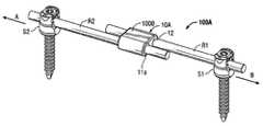
- FIG. 1Ais an isometric view of a bone fixation device with a first distance between a pair of pedicle screws
- FIG. 1Bis an isometric view of the bone fixation device of FIG. 1A with a second distance between the pair of pedicle screws;
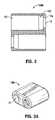
- FIG. 2is a top cross sectional view of a housing
- FIG. 3Ais an isometric view of a locking mechanism
- FIG. 3Bis an exploded view of the locking mechanism of FIG. 3A ;
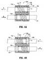
- FIG. 4Ais a cross sectional view of the locking mechanism of FIG. 3A in a locked state
- FIG. 4Bis a cross sectional view of the locking mechanism of FIG. 3A in an unlocked state
- FIG. 5Ais an exploded view of another embodiment of a bone fixation device
- FIG. 5Bis an assembled view of the bone fixation device of FIG. 5A ;
- FIG. 5Cis a cross sectional view of the bone fixation device of FIG. 5B ;
- FIG. 6Ais an isometric view of another embodiment of a bone fixation device with a first distance between a pair of pedicle screws;
- FIG. 6Bis an isometric view of the bone fixation device of FIG. 6A with a second distance between the pair of pedicle screws;
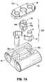
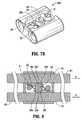
- FIG. 7Ais a fully exploded isometric view of a locking mechanism of the bone fixation device of FIGS. 6A-B ;
- FIG. 7Bis an isometric view of the locking mechanism of FIG. 7A with the cover removed;
- FIG. 8is a top cross sectional view of the locking mechanism of FIG. 7A with rods inserted therein;
- FIG. 9Ais an isometric view of another embodiment of a bone fixation device with a first distance between a pair of pedicle screws;
- FIG. 9Bis an isometric view of the bone fixation device of FIG. 9A with a second distance between the pair of pedicle screws;
- FIG. 10is an isometric view of another embodiment of a bone fixation device
- FIG. 11is an isometric view of another embodiment of a bone fixation device
- FIG. 12Ais an exploded view of the bone fixation device of FIG. 9A ;
- FIG. 12Bis top cross sectional view of the bone fixation device of FIG. 12A ;
- FIG. 13Ais an isometric view of another embodiment of a bone fixation device
- FIG. 13Bis a partially exploded isometric view of the bone fixation device of FIG. 13A ;
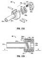
- FIG. 14Ais an isometric view of a further embodiment of a bone fixation device
- FIG. 14Bis an exploded view of the bone fixation device of FIG. 14A ;
- FIG. 14Cis a front view of the bone fixation device of FIG. 14A ;
- FIG. 15is an isometric view of a spinal construct with the bone fixation device of FIG. 14A , a plurality of rods, and a plurality of screws;
- FIG. 16Ais an isometric view of an alternate embodiment of a bone fixation device
- FIG. 16Bis an exploded view of the bone fixation device of FIG. 16A ;
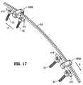
- FIG. 17is an isometric view of a spinal construct with the bone fixation device of FIG. 16A , a rod, and a plurality of screws;
- FIG. 18Ais an isometric view of a further embodiment of a bone fixation device
- FIG. 18Bis an exploded view of the bone fixation device of FIG. 18A ;
- FIG. 19is an isometric view of a spinal construct with the bone fixation device of FIG. 18A , a rod, and a plurality of screws.
- proximalwill refer to the end of a device or system that is closest to the operator
- distalwill refer to the end of the device or system that is farthest from the operator.
- cephaladis used in this application to indicate a direction toward a patient's head
- the term “caudad”indicates a direction toward the patient's feet.
- the term “medial”indicates a direction toward a side of the body of the patient, i.e., away from the middle of the body of the patient, while the term “lateral” indicates a direction toward a side of the body of the patient (i.e., away from the middle of the body of the patient).
- the term “posterior”indicates a direction towards the patient's back, and the term “anterior” indicates a direction toward the patient's front.
- Embodiments of a bone fixation device having a locking mechanism adapted for passively accommodating bone growth without the need for post installation adjustmentwill now be described with reference to FIGS. 1A to 13B .
- FIGS. 1A and 1BA first embodiment of a bone fixation device 100 A will now be described with reference to FIGS. 1A to 4B .
- the bone fixation device 100 Ais shown in FIGS. 1A and 1B illustrating a first distance between bone screws ( FIG. 1A ) and a second distance between bone screws ( FIG. 1B ).
- the bone fixation device 100 Aincludes a locking mechanism 10 A including two parallel through holes 12 adapted to receive rods R 1 , R 2 therein. Each rod R 1 , R 2 is adapted to be coupled to a bone screw S 1 , S 2 that is implantable into a bone (not shown) or vertebral body.
- the bone fixation device 100 Ais configured for attachment to two rods R 1 , R 2 which are disposed between screws S 1 , S 2 which may be coupled to two vertebral bodies, although the disclosed embodiments of the bone fixation device may be used for coupling a varying number of screws or vertebral bodies.
- a forceis exerted on the bone screws S 1 , S 2 to move them away from one another.
- the rods R 1 , R 2translate through the locking mechanism 10 A and the bone fixation device 100 A allows the distance between the pedicle screws S 1 , S 2 to increase from a first distance ( FIG. 1A ) to a second distance ( FIG.
- the presently disclosed bone fixation device 100 Aforms an implantable spinal construct when assembled with the bone screws S 1 , S 2 and the rods R 1 , R 2 as shown in FIGS. 1A and 1B .
- each through hole 12 within a housing 1000includes an opening 12 a which leads to a tapered section 102 having a diameter that gradually increases until reaching a section 101 having a generally constant diameter.
- Each through hole 12houses a split ring 10 and a spring element 11 that is held in place therein by a cap 11 a , as shown in FIGS. 3A and 3B .
- the locking mechanism 10 Ahas a locked state ( FIG. 4A ) and an unlocked state ( FIG. 4B ).
- the following discussionaddresses only one of the rods R 1 , R 2 and the description of the operation of the locking mechanism is applicable to both rods R 1 , R 2 .
- the spring element 11applies a constant force to the split ring 10 in a direction towards an opening 12 a along the tapered section 102 towards a smaller diameter section of the through hole 12 .
- the split ring 10has a variable diameter corresponding to the position of the split ring 10 along the tapered section 102 .
- the rod R 1is positioned within the split ring 10 and the spring element 11 .
- the split ring 10As the split ring 10 translates to an area of the tapered section 102 having a decreased diameter, the split ring 10 applies a circumferential, frictional force to the rod R 1 inhibiting translation of the rod R 1 in the direction of arrow A, as shown in FIG. 4A .
- the split ring 10translates to an area of the tapered section 102 having an increased diameter thereby permitting the split ring 10 to expand and correspondingly reduce the circumferential, frictional force applied by the split ring 10 to the rod R 1 positioned within the split ring 10 .
- the rod R 1may translate freely in the direction of arrow B as shown in FIG. 4B .
- the rod R 1is capable of translation in only one direction since application of a force translating the rod R 1 in the direction of opening 12 a will engage the locking mechanism, as shown in FIG. 4A .
- the bone fixation device 100 Ais capable of passively allowing the distance or space between a pair of pedicle screws S 1 , S 2 ( FIGS. 1A and 1B ) to increase in response to a patient's growth without physician adjustment or intervention.
- the locking mechanism 10 Aresists shortening of the overall construct or movement of the pedicle screws S 1 , S 2 towards each other. More specifically, as the distance between the pedicle screws S 1 , S 2 increases, rod R 1 translates through the locking mechanism 10 A in the direction of arrow B, while rod R 2 translates through the locking mechanism in the direction of arrow A.
- the bone fixation device 100 Bincludes a locking mechanism 10 B that functions substantially similarly to the locking mechanism 10 A of the bone fixation device 100 A in that the locking mechanism 10 B includes a through hole 2 housing the split ring 10 and the spring element 11 , held in place by the cap 11 a , and is adapted to receive the rod R 1 therein in a locked and an unlocked state depending upon the direction of the force applied to the rod R 1 .
- the spring element 11 and the cap 11 amay be formed as a unitary structure.
- the locking mechanism 10 Bhas a single through hole 2 adapted to receive two rods R 1 , R 2 co-linearly therein. Beginning at each end 2 a and 2 b of the through hole 2 is a section 101 b having a generally constant diameter until reaching a tapered section 102 b having a diameter that gradually decreases.
- the spring element 11applies a constant force to the split ring 10 in a direction toward the smaller end of the tapered section 102 b such that the split ring 10 is moved toward a smaller diameter section of the through hole 2 such that the split ring 10 compresses around the rod R 1 inserted therein, inhibiting translation of the rod R 1 in the direction indicated by arrow A.
- application of a force to the rods R 1 , R 2 in a direction that would lengthen the construct by moving the rod segments apart from each otheri.e.
- bone fixation device 100 Bcauses the split ring 10 to move to a section of the through hole 2 having a larger diameter thereby reducing the frictional force between the rods R 1 , R 2 and the split rings 10 allowing for translation of the rods R 1 , R 2 therein, wherein rod R 1 translates in the direction indicated by arrow B and rod R 1 translates in the direction indicated by arrow A.
- bone fixation device 100 Bforms an implantable spinal construct when assembled with bone screws and rods.
- the bone fixation device 200includes a locking mechanism 201 including two parallel through holes 26 adapted to receive rods R 1 , R 2 that are coupled to bone screws S 1 , S 2 implantable into a bone (not shown).
- the locking mechanism 201is configured and dimensioned to permit passive translation, i.e., without post-installation adjustment or surgical intervention, of the rods R 1 , R 2 in only one direction, i.e., in the direction of growing bone, while inhibiting translation in an opposite direction.
- the locking mechanism 201allows rod R 1 to move in the direction of arrow B and rod R 2 to move in the direction of arrow A, while inhibiting motion of the rods R 1 , R 2 in the opposing direction.
- the construct including bone fixation device 200may be installed such that a first distance is defined between a pair of pedicle screws S 1 , S 2 , as shown in FIG. 6A , and allows movement of the rods R 1 , R 2 in response to bone growth or a change in the spacing between the bones such that a second distance is defined between the pair of pedicle screws S 1 , S 2 as shown in FIG. 6B .
- bone fixation device 200allows a change in the spacing between the pedicle screws S 1 , S 2 without requiring physician intervention and also forms an implantable spinal construct when assembled with the bone screws S 1 , S 2 and the rods R 1 , R 2 as shown in FIGS. 6A and 6B .
- the through holes 26are generally open with the exception of a closed section 26 a adapted to stabilize the rods R 1 , R 2 inserted therein.
- a locking assembly 202Located between the two parallel through holes 26 is a locking assembly 202 , shown with parts separated in FIG. 7A .
- the locking assembly 202includes a cam 20 having two generally opposite cam surfaces 20 a and 20 b .
- the cam surface 20 ahas a rounded section 20 c and a pointed section 20 d , as shown in FIG. 8 .
- the cam surface 20 bhas a rounded section 20 f and a pointed section 20 e .
- Adjacent to and in contact with the cam 20are spring elements 22 held in place by posts 21 .
- the spring elements 22provide an opposing biasing force to the cam 20 resulting in a rotational force being applied to the cam 20 such the rounded sections 20 c and 20 f of the cam surfaces 20 b and 20 a , respectively, engage the rods R 1 , R 2 that are positioned within the through holes 26 , to thereby inhibit translation of the rods R 1 , R 2 therein.
- Application of a force to translate the rods R 1 , R 2 in a direction opposite and counteracting the rotation of the cam 20causes the rods R 1 , R 2 to engage the rounded sections 20 c and 20 f of the cam 20 .
- the cam 20rotates thereby increasing the frictional engagement of the rods R 1 , R 2 and the rounded sections 20 c and 20 f of the cam 20 .
- the rods R 1 , R 2attempt to move toward each other (i.e. rod R 1 in the direction of arrow A and rod R 2 in the direction of arrow B)
- the frictional engagement between the rods R 1 , R 2 and the rounded sections 20 c , 20 finhibit such motion.
- the rods R 1 , R 2are moved away from each other (i.e.
- the cam 20rotates in an opposite direction and overcomes the bias applied to the cam 20 by the spring elements 22 such that the rounded sections 20 c , 20 f disengage from the surfaces of the rods R 1 , R 2 and allow the rods R 1 , R 2 to move.
- the locking mechanism 201allows the rods R 1 , R 2 to move away from each other, thereby increasing the distance between the pair of pedicle screws S 1 , S 2 ( FIG. 6B ) and inhibits the rods R 1 , R 2 from moving towards each other for maintaining the distance between the pair of pedicle screws S 1 , S 2 .
- a clinicianmay manually rotate the cam 20 by utilizing a slot 25 in the surface of the cam 20 such that the rounded sections 20 c and 20 f do not engage the rods R 1 , R 2 such that the rods R 1 , R 2 may freely rotate.
- a cover 18is removable allowing a physician to view the inside of the locking mechanism 201 .
- a bone fixation device 301is disclosed and will now be described with reference to FIGS. 9A-9B .
- the bone fixation device 301is adapted for allowing rod R 1 to move in the direction of arrow A and inhibiting the movement of rod R 1 in the opposing direction.
- bone fixation device 301 in combination with rod R 1defines a first distance between a pair of pedicle screws S 1 , S 2 ( FIG. 9A ).
- the bone fixation device 301allows the rod R 1 to move in the direction of arrow A without physician intervention such that a second distance between the pair of pedicle screws S 1 , S 2 is defined ( FIG. 9B ).
- Bone fixation devices 302 and 303utilize substantially the same locking mechanism as will be described with reference to the bone fixation device 301 , differing only in configuration.
- Bone fixation devices 302 and 303are configured and adapted to work with rods R 1 , R 2 .
- the bone fixation devices 302 and 303are two such examples of alternate configurations.
- the bone fixation device 302includes a housing 315 having two parallel through holes 302 a adapted to receive rods R 1 , R 2 therein ( FIG. 10 ).
- the bone fixation device 303includes a housing 320 having two parallel through holes 303 a adapted to receive rods R 1 , R 2 therein ( FIG. 11 ).
- each of the through holes 302 a , 303 a of the bone fixation devices 302 , 303is a locking assembly 310 , as shown in FIG. 12A , to permit translation of the rods R 1 , R 2 in only one direction.
- bone fixation devices 301 , 302 , and 303form implantable spinal constructs when assembled with bone screws S 1 , S 2 and rods R 1 , R 2 as shown in FIGS. 9A-11 .
- FIGS. 9A-11disclose several embodiments of a particular theme of the bone fixation device.
- FIGS. 9A-9Bdepict an in-line device with a reduced overall profile.
- the presently disclosed bone fixation devicesare suitable for use in procedures with infants, children, and other persons having a small physique.
- the reduced profile of the bone fixation devicesis critical in reducing the likelihood of infection, reducing tissue irritation, and minimizing device protrusion on the backside of a patient. Current devices can be felt and are extremely noticeable when not covered by clothing and are aesthetically very undesirable.
- the outer diameter of the posts 301 b , 302 c , 303 cis substantially identical to the outside diameter of a spine rod that would be coupled to pedicle screw S 1 .
- a minimum wall thickness of posts 301 b , 302 c , 303 cmust be maintained so that bone fixation devices 301 , 302 , 303 do not fail under load. Therefore, the inner diameter of posts 301 b , 302 c , 303 c is reduced such that a smaller diameter rod is used in conjunction with bone fixation devices 301 , 302 , 303 .
- the smaller diameter rodhas a reduced strength in comparison to a larger diameter (i.e. standard rod) rod.
- the material of the rodcan be changed, but in some instances, even with a change in material from, for example, Ti-6Al-4V to CoCr, the rod diameter must remain the same or be larger in order to maintain the desired strength of the rod.
- bone fixation devices 302 , 303that are shown in FIGS. 10 and 11 , allow bone fixation devices 302 , 303 to be fixed to screw S 1 , as opposed to floating (e.g. FIGS. 1-8 ) and accommodate a spinal rod with an outside diameter that mates with a typical pedicle screw.
- a reduction of spinal rod diameteris necessary.
- split sleeve 40acts like a bushing and has an outer diameter matching the pedicle screw and an inner diameter matching the spinal rod.
- Split sleeve 40is made from a more malleable material which will deform more, under load, for securely locking the spinal rod.
- the device of FIGS. 9A-9Bwill not accommodate a curved rod to pass through since a substantial length of the device is straight.
- All spinal rods used in conjunction with the disclosed bone fixation devicesmay include a stop portion 317 ( FIG. 9A ) for preventing the rod from translating completely through the bone fixation device.
- Stop portion 317may be formed by swaging an end of the rod, in situ, but other structures, such as but not limited to collars, clamps, diametrical increases, etc. may be employed.
- the embodiment in FIG. 13is a variation of FIG. 9A wherein the device is in-line, as opposed to offset ( FIGS. 10 and 11 ) and provides a telescoping arrangement between the spinal rod and the bone fixation device rather than an arrangement for a spinal rod to translate through the bone fixation device.
- the embodiment of FIG. 13provides an arrangement for a spinal rod which inhibits rotation of the spinal rod about its long axis. Inhibiting rotation of the spinal rod about its long axis is important in preventing the rotation of the spine otherwise known as the “crankshaft” phenomena.
- the locking mechanism 301includes a post 301 b that is adapted to couple to a bone screw S 2 .
- a through hole 301 a within the post 301 bis adapted to receive the rod R 1 therein.
- the rod R 1passes through the entire locking mechanism 301 and includes a sleeve 40 positioned on the rod R 1 at a distal end thereof such that the bone screw S 1 can be coupled to the sleeve 40 .
- the locking mechanism 301includes the locking assembly 310 .
- the locking assembly 310includes one or more ring plates 306 , each having an aperture 306 a , the ring plate 306 positioned adjacent to a spring element 308 .
- the assembly 310is held within the locking mechanism 301 by an end cap 305 that includes an aperture 305 a .
- Each of the apertures 301 a , 306 a , and 305 aare aligned such that the rod R 1 may be positioned within the apertures 301 a , 306 a , and 305 a.
- the ring plates 306are held in place by a post 307 at one end 306 c while a constant force is applied to a second end 306 b by the spring element 308 , thereby rotating the ring plates 306 until the second end 306 b is prevented from further rotating by a surface 306 d of the locking mechanism 301 .
- the aperture 306 aexerts a frictional force that inhibits translation of the rod R 1 therethrough.
- the ring plates 306rotate in a direction to reduce the frictional force between the aperture 306 a and the rod R 1 , thereby permitting translation of the rod R 1 therethrough.
- a physician desire to permit the manual translation of the rod R 1 in either directionhe may depress the ring plates 306 by utilizing an aperture 312 in the locking mechanism 301 .
- the bone fixation device 300 Dincludes locking mechanism 304 that is configured and dimensioned to permit passive translation without post-installation adjustment of a rod T in only one direction, i.e., in a direction corresponding to the lengthening of a bone. This corresponds to the direction indicated by arrow A.
- the locking mechanism 304includes a housing 320 that has an aperture 324 adapted to receive a rod T therein and has a post 323 . Both the rod T and the post 323 are attachable to one or more bone screws S.
- the rod Tmay have a generally rectangular cross section.
- the rod plates 320have tabs 320 a and 320 b that frictionally engage a surface of the rod T to inhibit translation of the rod T.
- the frictional force between tabs 320 a and 320 b and the rod Tis lessened and the rod T translates through the aperture 324 .
- Bone fixation device 400is illustrated in FIGS. 14A-14C .
- Bone fixation device 400includes an upper arm 410 and a lower arm 420 .
- Upper arm 410includes an orifice 404 for receiving a screw 402 therein.
- Upper arm 410 and lower arm 420are joined together at one end while the opposing end is open, thereby allowing upper arm 410 to flex towards and away from lower arm 420 and vice versa.
- a channel 430is defined by inner surfaces 412 , 422 .
- Channel 430is substantially open at one end and is adapted for accommodating rods of varying diameters.
- Bone fixation deviceincludes orifices 442 , 444 in opposing sidewalls that are disposed in the vicinity of a chamber 436 .
- a pin 408is insertable through orifices 442 , 444 .
- a passage 440extends through bone fixation device 400 and is adapted for slidably receiving a rod R 3 ( FIG. 15 ).
- rod R 3has flat top and bottom surfaces with curved side surfaces ( FIG. 15 ).
- Passage 440has a geometric configuration that is complementary to the geometry of rod R 3 with an overall inner diameter that is slightly greater than the outer diameter of rod R 3 which minimized “crankshafting” of the rod R 3 with respect to the bone fixation device 400 or the assembled construct.
- a locking mechanism 450is disposed in chamber 436 of bone fixation device 400 . Locking mechanism 450 includes one or more ring plates 452 .
- Each ring plate 452includes a through hole 456 , an opening 454 , and a spring member 458 .
- a bore 459 of spring member 458is aligned with opening 454 and orifices 442 , 444 .
- pin 408is inserted therethrough and secures locking mechanism 450 within chamber 436 since pin 408 passes through orifice 442 , bore 459 of spring member 458 , opening 454 , and orifice 444 .
- Spring member 458biases ring plate 452 in a first direction shown as arrow B in FIG. 14A .
- passage 440is substantially aligned with through hole 456 and the openings of passage 440 such that rod R 3 is repositionable through bone fixation device 400 in the direction indicated by arrow A.
- frictional engagement between an outer surface of rod R 3 and an inner surface of through hole 456overcomes the bias of spring member 458 and repositions ring plate 452 in the direction indicated by arrow A.
- through hole 456is out of alignment with passage 440 (i.e. askew with respect to a longitudinal axis extending through passage 440 ), thereby increasing the frictional engagement between through hole 456 and the outer surface of rod R 3 .
- locking mechanism 450allows relative movement between bone fixation device 400 and rod R 3 in the direction indicated by arrow A, while inhibiting relative movement between bone fixation device 400 and rod R 3 in the direction indicated by arrow B.
- the dimensions of passage 440 of bone fixation device 400are greater than the dimensions of through hole 456 of ring plate 452 . This arrangement allows a curved rod to pass through ring plate 452 and passage 440 , since the device's run on rod R 3 is a short distance.
- a bone fixation device 401may have the orientation of the locking mechanism 450 reversed.
- spring member 458biases ring plate 452 in the direction indicated by arrow A.
- rod R 3is repositionable relative to bone fixation device 401 in the direction indicated by arrow B and is inhibited from moving relative to bone fixation device 401 in the direction indicated by arrow A ( FIG. 15 ).
- Bone fixation devices 400 , 401form part of a surgical construct as illustrated in FIG. 15 .
- bone fixation devices 400 , 401are operably coupled to a rod R 1 that is inserted through channel 430 and secured therein by tightening screw 402 .
- Rod R 1spans a pair of pedicle screws S 1 , S 2 and defines an anchor location for bone fixation devices 400 , 401 .
- Rod R 3is inserted through bone fixation devices 400 , 401 via passage 440 .
- multiple bone fixation devices 400 , 401are utilized along with corresponding rods R 1 and pedicle screws S 1 , S 2 . As the spacing between anchor points along rod R 3 increases (e.g.
- rod R 3translates through bone fixation device 400 in the direction shown as arrow A and is inhibited from translating through bone fixation device 400 in the direction shown as arrow A due to the interaction between rod R 3 and locking mechanism 450 as discussed hereinabove.
- rod R 3translates through bone fixation device 401 in the direction of arrow B and is inhibited from translating through bone fixation device 401 in the direction of arrow A.
- Bone fixation device 400 A( FIGS. 16A-16B ) is similar to bone fixation device 400 discussed in detail hereinabove with like reference characters identifying like components.
- Bone fixation device 400 Aincludes a body 405 having a chamber 436 disposed at one end thereof.
- a locking mechanism 450is disposed in chamber 436 and secured in position by pin 408 that extends through orifices 442 , 444 , bore 459 of spring member 458 , and opening 454 of ring plate 452 .
- Rod R 3interacts with bone fixation device 400 A in the same manner that it interacts with bone fixation device 400 as discussed hereinabove.
- extensions 417 , 419are attached to body 405 at an end that is opposite to chamber 436 .
- Extensions 417 , 419are generally round and are adapted for coupling with pedicle screws S 1 , S 2 ( FIG. 17 ). Additionally, extensions 417 , 419 extend from body 405 in a direction that is substantially parallel to passage 440 and thus rod R 3 ( FIG. 17 ).
- rod R 3interacts with locking mechanism 450 such that rod R 3 readily translates through bone fixation device 400 A in the direction indicated by arrow B ( FIG. 17 ) and is inhibited from translating relative to bone fixation device 400 A in the direction indicated by arrow A ( FIG. 17 ).
- Bone fixation device 400 A in cooperation with pedicle screws S 1 , S 2forms an anchor point for the assembled construct.
- Each pedicle screw S 1 , S 2is attached to a bone structure, such as a vertebral body.
- Bone fixation device 400 Bis similar to bone fixation device 400 discussed in detail hereinabove with like reference characters identifying like components and the differences being noted hereinafter.
- Bone fixation device 400 Bincludes a body 409 having a chamber 436 disposed at one end thereof.
- a locking mechanism 450is disposed in chamber 436 and secured in position by pin 408 that extends through orifices 442 , 444 , bore 459 of spring member 458 , and opening 454 of ring plate 452 .
- Rod R 3interacts with bone fixation device 400 B in the same manner that it interacts with bone fixation devices 400 , 400 A as discussed hereinabove.
- extension 427is attached to body 409 at an end that is opposite to chamber 436 .
- Extension 427is generally round and is adapted for coupling with pedicle screw S 1 ( FIG. 19 ).
- extension 427extends substantially perpendicular to passage 440 and is generally aligned with chamber 436 such that it is generally orthogonal with respect to rod R 3 ( FIG. 19 ).
- rod R 3interacts with locking mechanism 450 such that rod R 3 readily translates through bone fixation device 400 B in the direction indicated by arrow B ( FIG. 19 ) and is inhibited from translating relative to bone fixation device 400 B in the direction indicated by arrow A ( FIG. 19 ).
- Bone fixation device 400 B in cooperation with pedicle screw S 1forms an anchor point for the assembled construct.
- Each pedicle screw S 1is attached to a bone structure, such as a vertebral body.
- the embodiments described hereinmay be used for stabilizing any growing bone, including stabilizing the vertebrae of the spine of a patient who is still growing.
- Specific examples of bone screws that may be attached to the devices described hereininclude the pedicle screws described in U.S. Pat. Nos. 5,683,392; 5,733,286; 6,457,021, 7,090,674; U.S. Application Nos. 2007/0093817 and 2008/0027432, and International App. Ser. Nos. PCT/US08/80668 and PCT/US08/80682.
Landscapes
- Health & Medical Sciences (AREA)
- Orthopedic Medicine & Surgery (AREA)
- Life Sciences & Earth Sciences (AREA)
- Neurology (AREA)
- Surgery (AREA)
- Heart & Thoracic Surgery (AREA)
- Engineering & Computer Science (AREA)
- Biomedical Technology (AREA)
- Nuclear Medicine, Radiotherapy & Molecular Imaging (AREA)
- Medical Informatics (AREA)
- Molecular Biology (AREA)
- Animal Behavior & Ethology (AREA)
- General Health & Medical Sciences (AREA)
- Public Health (AREA)
- Veterinary Medicine (AREA)
- Surgical Instruments (AREA)
Abstract
Description
Claims (6)
Priority Applications (2)
| Application Number | Priority Date | Filing Date | Title |
|---|---|---|---|
| US12/368,029US8777995B2 (en) | 2008-02-07 | 2009-02-09 | Automatic lengthening bone fixation device |
| US14/313,371US9339307B2 (en) | 2008-02-07 | 2014-06-24 | Automatic lengthening bone fixation device |
Applications Claiming Priority (4)
| Application Number | Priority Date | Filing Date | Title |
|---|---|---|---|
| US6394308P | 2008-02-07 | 2008-02-07 | |
| US6394208P | 2008-02-07 | 2008-02-07 | |
| US18808908P | 2008-08-06 | 2008-08-06 | |
| US12/368,029US8777995B2 (en) | 2008-02-07 | 2009-02-09 | Automatic lengthening bone fixation device |
Related Child Applications (1)
| Application Number | Title | Priority Date | Filing Date |
|---|---|---|---|
| US14/313,371DivisionUS9339307B2 (en) | 2008-02-07 | 2014-06-24 | Automatic lengthening bone fixation device |
Publications (2)
| Publication Number | Publication Date |
|---|---|
| US20090204156A1 US20090204156A1 (en) | 2009-08-13 |
| US8777995B2true US8777995B2 (en) | 2014-07-15 |
Family
ID=40939554
Family Applications (2)
| Application Number | Title | Priority Date | Filing Date |
|---|---|---|---|
| US12/368,029Expired - Fee RelatedUS8777995B2 (en) | 2008-02-07 | 2009-02-09 | Automatic lengthening bone fixation device |
| US14/313,371Active2029-04-28US9339307B2 (en) | 2008-02-07 | 2014-06-24 | Automatic lengthening bone fixation device |
Family Applications After (1)
| Application Number | Title | Priority Date | Filing Date |
|---|---|---|---|
| US14/313,371Active2029-04-28US9339307B2 (en) | 2008-02-07 | 2014-06-24 | Automatic lengthening bone fixation device |
Country Status (5)
| Country | Link |
|---|---|
| US (2) | US8777995B2 (en) |
| EP (1) | EP2244644A1 (en) |
| JP (1) | JP2011511676A (en) |
| AU (1) | AU2009212126A1 (en) |
| WO (1) | WO2009100429A1 (en) |
Cited By (41)
| Publication number | Priority date | Publication date | Assignee | Title |
|---|---|---|---|---|
| US20140303674A1 (en)* | 2011-11-18 | 2014-10-09 | Orthopaedic International, Inc. | Parallel rod connector |
| US20150080958A1 (en)* | 2010-01-05 | 2015-03-19 | The Johns Hopkins University | Compression-distraction spinal fixation system |
| US20180125533A1 (en)* | 2015-04-17 | 2018-05-10 | Apifix Ltd. | Expandable polyaxial spinal system |
| US10016220B2 (en) | 2011-11-01 | 2018-07-10 | Nuvasive Specialized Orthopedics, Inc. | Adjustable magnetic devices and methods of using same |
| US10039661B2 (en) | 2006-10-20 | 2018-08-07 | Nuvasive Specialized Orthopedics, Inc. | Adjustable implant and method of use |
| US10198970B2 (en) | 2014-07-14 | 2019-02-05 | K2M, Inc. | Growing spine model |
| US10238427B2 (en) | 2015-02-19 | 2019-03-26 | Nuvasive Specialized Orthopedics, Inc. | Systems and methods for vertebral adjustment |
| US10271885B2 (en) | 2014-12-26 | 2019-04-30 | Nuvasive Specialized Orthopedics, Inc. | Systems and methods for distraction |
| US10349995B2 (en) | 2007-10-30 | 2019-07-16 | Nuvasive Specialized Orthopedics, Inc. | Skeletal manipulation method |
| US10405891B2 (en) | 2010-08-09 | 2019-09-10 | Nuvasive Specialized Orthopedics, Inc. | Maintenance feature in magnetic implant |
| US10478232B2 (en) | 2009-04-29 | 2019-11-19 | Nuvasive Specialized Orthopedics, Inc. | Interspinous process device and method |
| US10517643B2 (en) | 2009-02-23 | 2019-12-31 | Nuvasive Specialized Orthopedics, Inc. | Non-invasive adjustable distraction system |
| US10617453B2 (en) | 2015-10-16 | 2020-04-14 | Nuvasive Specialized Orthopedics, Inc. | Adjustable devices for treating arthritis of the knee |
| US10646262B2 (en) | 2011-02-14 | 2020-05-12 | Nuvasive Specialized Orthopedics, Inc. | System and method for altering rotational alignment of bone sections |
| US10660675B2 (en) | 2010-06-30 | 2020-05-26 | Nuvasive Specialized Orthopedics, Inc. | External adjustment device for distraction device |
| US10729470B2 (en) | 2008-11-10 | 2020-08-04 | Nuvasive Specialized Orthopedics, Inc. | External adjustment device for distraction device |
| US10743794B2 (en) | 2011-10-04 | 2020-08-18 | Nuvasive Specialized Orthopedics, Inc. | Devices and methods for non-invasive implant length sensing |
| US10751094B2 (en) | 2013-10-10 | 2020-08-25 | Nuvasive Specialized Orthopedics, Inc. | Adjustable spinal implant |
| US10835290B2 (en) | 2015-12-10 | 2020-11-17 | Nuvasive Specialized Orthopedics, Inc. | External adjustment device for distraction device |
| US10918425B2 (en) | 2016-01-28 | 2021-02-16 | Nuvasive Specialized Orthopedics, Inc. | System and methods for bone transport |
| US20210196327A1 (en)* | 2019-12-25 | 2021-07-01 | Apifix Ltd. | Biasing device for spinal device |
| US11191579B2 (en) | 2012-10-29 | 2021-12-07 | Nuvasive Specialized Orthopedics, Inc. | Adjustable devices for treating arthritis of the knee |
| US11202707B2 (en) | 2008-03-25 | 2021-12-21 | Nuvasive Specialized Orthopedics, Inc. | Adjustable implant system |
| US11207110B2 (en) | 2009-09-04 | 2021-12-28 | Nuvasive Specialized Orthopedics, Inc. | Bone growth device and method |
| US11246694B2 (en) | 2014-04-28 | 2022-02-15 | Nuvasive Specialized Orthopedics, Inc. | System for informational magnetic feedback in adjustable implants |
| USRE49061E1 (en) | 2012-10-18 | 2022-05-10 | Nuvasive Specialized Orthopedics, Inc. | Intramedullary implants for replacing lost bone |
| US11357549B2 (en) | 2004-07-02 | 2022-06-14 | Nuvasive Specialized Orthopedics, Inc. | Expandable rod system to treat scoliosis and method of using the same |
| US11357547B2 (en) | 2014-10-23 | 2022-06-14 | Nuvasive Specialized Orthopedics Inc. | Remotely adjustable interactive bone reshaping implant |
| US11547450B2 (en)* | 2015-04-17 | 2023-01-10 | Apifix Ltd. | Expandable polyaxial spinal system |
| US11577097B2 (en) | 2019-02-07 | 2023-02-14 | Nuvasive Specialized Orthopedics, Inc. | Ultrasonic communication in medical devices |
| US11589901B2 (en) | 2019-02-08 | 2023-02-28 | Nuvasive Specialized Orthopedics, Inc. | External adjustment device |
| US11696836B2 (en) | 2013-08-09 | 2023-07-11 | Nuvasive, Inc. | Lordotic expandable interbody implant |
| US11737787B1 (en) | 2021-05-27 | 2023-08-29 | Nuvasive, Inc. | Bone elongating devices and methods of use |
| US11766252B2 (en) | 2013-07-31 | 2023-09-26 | Nuvasive Specialized Orthopedics, Inc. | Noninvasively adjustable suture anchors |
| US11801187B2 (en) | 2016-02-10 | 2023-10-31 | Nuvasive Specialized Orthopedics, Inc. | Systems and methods for controlling multiple surgical variables |
| US11806054B2 (en) | 2021-02-23 | 2023-11-07 | Nuvasive Specialized Orthopedics, Inc. | Adjustable implant, system and methods |
| US11839410B2 (en) | 2012-06-15 | 2023-12-12 | Nuvasive Inc. | Magnetic implants with improved anatomical compatibility |
| US11857226B2 (en) | 2013-03-08 | 2024-01-02 | Nuvasive Specialized Orthopedics | Systems and methods for ultrasonic detection of device distraction |
| US11925389B2 (en) | 2008-10-13 | 2024-03-12 | Nuvasive Specialized Orthopedics, Inc. | Spinal distraction system |
| US12023073B2 (en) | 2021-08-03 | 2024-07-02 | Nuvasive Specialized Orthopedics, Inc. | Adjustable implant |
| US12213708B2 (en) | 2020-09-08 | 2025-02-04 | Nuvasive Specialized Orthopedics, Inc. | Remote control module for adjustable implants |
Families Citing this family (62)
| Publication number | Priority date | Publication date | Assignee | Title |
|---|---|---|---|---|
| US8114158B2 (en) | 2004-08-03 | 2012-02-14 | Kspine, Inc. | Facet device and method |
| US8398637B2 (en)* | 2006-11-06 | 2013-03-19 | Douglas Eric Parsell | Device and method for less invasive surgical stabilization of pelvic fractures |
| US20090105756A1 (en) | 2007-10-23 | 2009-04-23 | Marc Richelsoph | Spinal implant |
| US8292930B2 (en)* | 2008-05-06 | 2012-10-23 | Warsaw Orthopedic, Inc. | Tethering devices and methods to treat a spinal deformity |
| US8197516B2 (en)* | 2008-07-01 | 2012-06-12 | The University Of Toledo | Lateral fixation assembly for spinal column |
| EP2484300B1 (en)* | 2008-09-05 | 2015-05-20 | Biedermann Technologies GmbH & Co. KG | Stabilization device for bones, in particular for the spinal column |
| US9603629B2 (en)* | 2008-09-09 | 2017-03-28 | Intelligent Implant Systems Llc | Polyaxial screw assembly |
| EP2174608B1 (en)* | 2008-10-08 | 2012-08-01 | Biedermann Technologies GmbH & Co. KG | Bone anchoring device and stabilization device for bone parts or vertebrae |
| GB2465156B (en)* | 2008-11-05 | 2012-09-26 | Dalmatic Lystrup As | Bone fixation system |
| US8828058B2 (en)* | 2008-11-11 | 2014-09-09 | Kspine, Inc. | Growth directed vertebral fixation system with distractible connector(s) and apical control |
| US8357182B2 (en) | 2009-03-26 | 2013-01-22 | Kspine, Inc. | Alignment system with longitudinal support features |
| US9168071B2 (en) | 2009-09-15 | 2015-10-27 | K2M, Inc. | Growth modulation system |
| WO2011112748A2 (en) | 2010-03-10 | 2011-09-15 | Saechin Kim | Spinal surgical apparatus and method of treating an abnormally shaped spine |
| EP2555696B1 (en)* | 2010-04-08 | 2017-07-26 | Globus Medical, Inc. | Jointed rod |
| US20120271353A1 (en)* | 2010-08-16 | 2012-10-25 | Mark Barry | System and method for aligning vertebrae in the amelioration of aberrant spinal column deviation conditions in patients requiring the accomodation of spinal column growth or elongation |
| US11154335B2 (en)* | 2010-09-27 | 2021-10-26 | Apifix Ltd. | Ratcheted spinal device |
| EP2460482A1 (en)* | 2010-12-03 | 2012-06-06 | Zimmer Spine | Rod holding device |
| FR2969479B1 (en) | 2010-12-23 | 2013-11-22 | Univ Claude Bernard Lyon | DEVICE FOR CORRECTING SCOLIOSIS AND FIGHT AGAINST ARTHRODESIS OF VERTEBRATES |
| US8828059B2 (en)* | 2011-04-25 | 2014-09-09 | Warsaw Orthopedic, Inc. | Elongated connecting elements for minimally invasive surgical procedures |
| JP6158176B2 (en) | 2011-06-03 | 2017-07-05 | ケイツーエム インコーポレイテッドK2M,Inc. | Spine correction system |
| US8998956B2 (en)* | 2011-07-15 | 2015-04-07 | Globus Medical, Inc. | Coupling devices and methods of using the same |
| US9468468B2 (en) | 2011-11-16 | 2016-10-18 | K2M, Inc. | Transverse connector for spinal stabilization system |
| US9468469B2 (en) | 2011-11-16 | 2016-10-18 | K2M, Inc. | Transverse coupler adjuster spinal correction systems and methods |
| US8920472B2 (en) | 2011-11-16 | 2014-12-30 | Kspine, Inc. | Spinal correction and secondary stabilization |
| WO2014172632A2 (en) | 2011-11-16 | 2014-10-23 | Kspine, Inc. | Spinal correction and secondary stabilization |
| US9451987B2 (en) | 2011-11-16 | 2016-09-27 | K2M, Inc. | System and method for spinal correction |
| US8808328B2 (en)* | 2012-04-05 | 2014-08-19 | Tufts Medical Center, Inc. | Spring loaded mechanism for managing scoliosis |
| EP2662037B1 (en)* | 2012-05-09 | 2023-01-11 | CoLigne AG | Iliac connector, connector head and spinal fixation system |
| US9427261B2 (en)* | 2012-06-13 | 2016-08-30 | Warsaw Orthopedic, Inc. | Spinal correction system and method |
| FR3001122B1 (en)* | 2013-01-23 | 2015-02-27 | Euros Sa | AUTOMATIC ELONGATION IMPLANT |
| WO2014145470A2 (en)* | 2013-03-15 | 2014-09-18 | Agarwal Anand K | Spinal rods formed from polymer and hybrid materials and growth rod distraction system including same |
| US9468471B2 (en) | 2013-09-17 | 2016-10-18 | K2M, Inc. | Transverse coupler adjuster spinal correction systems and methods |
| US9044273B2 (en) | 2013-10-07 | 2015-06-02 | Intelligent Implant Systems, Llc | Polyaxial plate rod system and surgical procedure |
| US10463400B2 (en) | 2014-02-28 | 2019-11-05 | The General Hospital Corporation | Bone surgical apparatus with ratcheting function |
| US9931138B2 (en)* | 2014-10-15 | 2018-04-03 | Globus Medical, Inc. | Orthopedic extendable rods |
| CA2917676A1 (en) | 2015-01-13 | 2016-07-13 | Stryker European Holdings I, Llc | Growing rods and methods of use |
| WO2016131094A1 (en)* | 2015-02-17 | 2016-08-25 | The Sydney Children's Hospitals Network (Randwick And Westmead) | A bone rod |
| RU2645960C2 (en)* | 2015-11-26 | 2018-02-28 | Андрей Александрович Карпушин | Growing four-plate structure for treatment of curvature, injuries and diseases of the spine in children |
| US10321939B2 (en) | 2016-05-18 | 2019-06-18 | Medos International Sarl | Implant connectors and related methods |
| US10517647B2 (en) | 2016-05-18 | 2019-12-31 | Medos International Sarl | Implant connectors and related methods |
| US10398476B2 (en) | 2016-12-13 | 2019-09-03 | Medos International Sàrl | Implant adapters and related methods |
| US10492835B2 (en) | 2016-12-19 | 2019-12-03 | Medos International Sàrl | Offset rods, offset rod connectors, and related methods |
| US10238432B2 (en) | 2017-02-10 | 2019-03-26 | Medos International Sàrl | Tandem rod connectors and related methods |
| US10561454B2 (en) | 2017-03-28 | 2020-02-18 | Medos International Sarl | Articulating implant connectors and related methods |
| US10966761B2 (en) | 2017-03-28 | 2021-04-06 | Medos International Sarl | Articulating implant connectors and related methods |
| US10610262B2 (en)* | 2017-05-24 | 2020-04-07 | Umc Utrecht Holding B.V. | Spinal distraction system |
| WO2019104255A1 (en)* | 2017-11-24 | 2019-05-31 | Craniofacial Technologies Inc. | Improved maxillary expander and protraction device |
| US11076890B2 (en) | 2017-12-01 | 2021-08-03 | Medos International Sàrl | Rod-to-rod connectors having robust rod closure mechanisms and related methods |
| US11446064B2 (en) | 2018-04-26 | 2022-09-20 | Stryker European Operations Holdings Llc | Orthopedic growing devices |
| US11382665B2 (en)* | 2018-06-11 | 2022-07-12 | Spinal Resources, Inc. | Variable-dimension fixation rod and implantable stabilization system including a variable-dimension fixation rod |
| US11147595B2 (en) | 2018-10-19 | 2021-10-19 | K2M, Inc. | Occipital plate with angled screw opening |
| CN109602486B (en)* | 2018-12-31 | 2020-12-04 | 武汉德骼拜尔外科植入物有限公司 | Universal connector for internal fixation of spine |
| US10893894B2 (en)* | 2019-04-24 | 2021-01-19 | Aesculap Implant Systems, Llc | Transverse coupling for surgical implant extensions |
| EP4106650A1 (en)* | 2020-02-21 | 2022-12-28 | Inno4Spine AG | Connector implant for connecting two posterior rod portions |
| EP3943028B1 (en) | 2020-07-22 | 2023-10-04 | Biedermann Technologies GmbH & Co. KG | Rod system including at least two rods and connector device for rods |
| NL2026643B1 (en)* | 2020-10-08 | 2022-06-07 | Umc Utrecht Holding Bv | Connector for spinal correction |
| CN113332004A (en)* | 2021-04-28 | 2021-09-03 | 北京市春立正达医疗器械股份有限公司 | Ulna prosthesis |
| US20240074797A1 (en)* | 2021-12-01 | 2024-03-07 | Matthew Amarante | Capped Distraction/Compression Rod System |
| US11812997B2 (en)* | 2022-03-10 | 2023-11-14 | King Saud University | System and method for treating early onset scoliosis |
| US12366078B2 (en)* | 2022-05-09 | 2025-07-22 | Burmon Holdings Pty Ltd. | Structural connector for tensioning floor joists and beams |
| KR102708571B1 (en)* | 2022-05-24 | 2024-09-24 | 충남대학교 산학협력단 | Pneumatic distractor for orthopaedic surgery |
| TWI846646B (en)* | 2023-11-22 | 2024-06-21 | 寶楠生技股份有限公司 | A scoliosis correction device that can automatically adjust with the growth of the spine |
Citations (45)
| Publication number | Priority date | Publication date | Assignee | Title |
|---|---|---|---|---|
| US4157715A (en)* | 1977-03-25 | 1979-06-12 | Erhard Westerhoff | Intracorporal drive to produce a continuous traction or pressure and method of operating the same |
| US4567884A (en)* | 1982-12-01 | 1986-02-04 | Edwards Charles C | Spinal hook |
| US4929247A (en) | 1988-10-06 | 1990-05-29 | Rayhack John M | Bone compression and distraction device |
| US5034011A (en)* | 1990-08-09 | 1991-07-23 | Advanced Spine Fixation Systems Incorporated | Segmental instrumentation of the posterior spine |
| US5281222A (en) | 1992-06-30 | 1994-01-25 | Zimmer, Inc. | Spinal implant system |
| US5330473A (en) | 1993-03-04 | 1994-07-19 | Advanced Spine Fixation Systems, Inc. | Branch connector for spinal fixation systems |
| US5380323A (en) | 1993-06-16 | 1995-01-10 | Advanced Spine Fixation Systems, Inc. | Clamps for spinal fixation systems |
| US5451226A (en) | 1989-03-06 | 1995-09-19 | Pfeil; Joachim | Unilateral, extensible, external tensioning device for treating bone diseases |
| US5466261A (en) | 1992-11-19 | 1995-11-14 | Wright Medical Technology, Inc. | Non-invasive expandable prosthesis for growing children |
| US5630816A (en) | 1995-05-01 | 1997-05-20 | Kambin; Parviz | Double barrel spinal fixation system and method |
| US5720746A (en) | 1994-11-16 | 1998-02-24 | Soubeiran; Arnaud Andre | Device for displacing two bodies relative to each other |
| US5766173A (en) | 1993-06-10 | 1998-06-16 | Texas Scottish Rite Hospital For Children | Distractor mechanism for external fixation device |
| US5928231A (en)* | 1995-05-19 | 1999-07-27 | Klein; Jean-Michel | Implantable osteosynthesis device |
| US5947966A (en) | 1995-06-06 | 1999-09-07 | Sdgi Holdings, Inc. | Device for linking adjacent rods in spinal instrumentation |
| US6136000A (en) | 1996-01-19 | 2000-10-24 | Louis; Rene | Anchoring device for posterior vertebral osteosynthesis |
| US6136003A (en) | 1995-06-06 | 2000-10-24 | Sdgi Holdings, Inc. | Device for linking adjacent rods in spinal instrumentation |
| US6277119B1 (en) | 1999-10-21 | 2001-08-21 | Electro-Biology, Inc. | External fixation system |
| US6602253B2 (en) | 2001-02-12 | 2003-08-05 | Marc Richelsoph | Rod to rod connector |
| US6616664B2 (en) | 1999-10-21 | 2003-09-09 | Ebi L.P. | Clamp assembly for an external fixation system |
| US20030220643A1 (en)* | 2002-05-24 | 2003-11-27 | Ferree Bret A. | Devices to prevent spinal extension |
| US6918910B2 (en) | 2002-12-16 | 2005-07-19 | John T. Smith | Implantable distraction device |
| US20050171543A1 (en) | 2003-05-02 | 2005-08-04 | Timm Jens P. | Spine stabilization systems and associated devices, assemblies and methods |
| US20050228378A1 (en) | 2004-03-31 | 2005-10-13 | Iain Kalfas | Spinal rod connector |
| US20050246034A1 (en) | 2002-08-30 | 2005-11-03 | Arnaud Soubeiran | Implantable mechanical device with adjustable geometry |
| US20050261779A1 (en) | 2003-11-17 | 2005-11-24 | Meyer Rudolf X | Expansible rod-type prosthesis and external magnetic apparatus |
| US20060009767A1 (en) | 2004-07-02 | 2006-01-12 | Kiester P D | Expandable rod system to treat scoliosis and method of using the same |
| US6991632B2 (en) | 2001-09-28 | 2006-01-31 | Stephen Ritland | Adjustable rod and connector device and method of use |
| US7004943B2 (en) | 2002-02-04 | 2006-02-28 | Smith & Nephew, Inc. | Devices, systems, and methods for placing and positioning fixation elements in external fixation systems |
| US20060079892A1 (en) | 2001-10-31 | 2006-04-13 | Suranjan Roychowdhury | Adjustable tandem connectors for corrective devices for the spinal column and other bones and joints |
| US7029472B1 (en) | 1999-06-01 | 2006-04-18 | Fortin Frederic | Distraction device for the bones of children |
| US20060155279A1 (en) | 2004-10-28 | 2006-07-13 | Axial Biotech, Inc. | Apparatus and method for concave scoliosis expansion |
| US20060195087A1 (en) | 2005-02-02 | 2006-08-31 | Ronald Sacher | Adjustable length implant |
| US20060195088A1 (en) | 2005-02-02 | 2006-08-31 | Ronald Sacher | Adjustable length implant |
| US20060233597A1 (en) | 2005-04-18 | 2006-10-19 | Ensign Micheal D | Cam based rod connection system and method |
| US7214226B2 (en) | 2002-07-24 | 2007-05-08 | Nas Spine, Inc. | Compressible fixation apparatus for spinal surgery |
| US20070173837A1 (en) | 2005-11-18 | 2007-07-26 | William Marsh Rice University | Bone fixation and dynamization devices and methods |
| US20070191845A1 (en) | 2006-01-31 | 2007-08-16 | Sdgi Holdings, Inc. | Expandable spinal rods and methods of use |
| US20070233070A1 (en) | 2006-03-01 | 2007-10-04 | Sdgi Holdings, Inc. | Low profile spinal rod connector system |
| US20070282339A1 (en) | 2006-04-29 | 2007-12-06 | Frank Johann Schwab | Variable connector |
| US20080027436A1 (en) | 2006-07-14 | 2008-01-31 | John Cournoyer | Rod to Rod Connectors and Methods of Adjusting The Length Of A Spinal Rod Construct |
| US20080051788A1 (en)* | 2006-08-21 | 2008-02-28 | Schwab Frank J | System And Method For Correcting Spinal Deformity |
| US20090306717A1 (en)* | 2008-05-28 | 2009-12-10 | James Kercher | Fluid-powered elongation instrumentation for correcting orthopedic deformities |
| US7632293B2 (en)* | 2003-09-29 | 2009-12-15 | Synthes Usa, Llc | Dynamic damping element for two bones |
| US20100106192A1 (en)* | 2008-10-27 | 2010-04-29 | Barry Mark A | System and method for aligning vertebrae in the amelioration of aberrant spinal column deviation condition in patients requiring the accomodation of spinal column growth or elongation |
| US20100198261A1 (en)* | 2007-10-09 | 2010-08-05 | Warsaw Orthopedic, Inc. | Adjustable spinal stabilization systems |
Family Cites Families (7)
| Publication number | Priority date | Publication date | Assignee | Title |
|---|---|---|---|---|
| BE1013222A3 (en)* | 2000-01-11 | 2001-11-06 | Mommaerts Maurice Yves | APPARATUS FOR INTRA-ORAL DISTRACTIEOSTEOTOMIE to widen the upper jaw. |
| GB0106588D0 (en)* | 2001-03-16 | 2001-05-09 | Finsbury Dev Ltd | Tissue distracter |
| US6602252B2 (en)* | 2002-01-03 | 2003-08-05 | Starion Instruments Corporation | Combined dissecting, cauterizing, and stapling device |
| FR2891727B1 (en)* | 2005-10-06 | 2008-09-26 | Frederic Fortin | PERFECTED AUTOBLOCATION DEVICE FOR COSTAL DISTRACTION DEVICE |
| US8685026B2 (en)* | 2008-05-23 | 2014-04-01 | Warsaw Orthopedic, Inc. | Devices and methods for releasing tension on a surgical tether |
| US20100292736A1 (en)* | 2009-05-15 | 2010-11-18 | Warsaw Orthopedic, Inc. | Linkage for Connection of Fusion and Non-Fusion Systems |
| US20110009906A1 (en)* | 2009-07-13 | 2011-01-13 | Zimmer Spine, Inc. | Vertebral stabilization transition connector |
- 2009
- 2009-02-09JPJP2010546089Apatent/JP2011511676A/enactivePending
- 2009-02-09USUS12/368,029patent/US8777995B2/ennot_activeExpired - Fee Related
- 2009-02-09AUAU2009212126Apatent/AU2009212126A1/ennot_activeAbandoned
- 2009-02-09EPEP09708277Apatent/EP2244644A1/ennot_activeWithdrawn
- 2009-02-09WOPCT/US2009/033553patent/WO2009100429A1/enactiveApplication Filing
- 2014
- 2014-06-24USUS14/313,371patent/US9339307B2/enactiveActive
Patent Citations (48)
| Publication number | Priority date | Publication date | Assignee | Title |
|---|---|---|---|---|
| US4157715A (en)* | 1977-03-25 | 1979-06-12 | Erhard Westerhoff | Intracorporal drive to produce a continuous traction or pressure and method of operating the same |
| US4567884A (en)* | 1982-12-01 | 1986-02-04 | Edwards Charles C | Spinal hook |
| US4929247A (en) | 1988-10-06 | 1990-05-29 | Rayhack John M | Bone compression and distraction device |
| US5451226A (en) | 1989-03-06 | 1995-09-19 | Pfeil; Joachim | Unilateral, extensible, external tensioning device for treating bone diseases |
| US5034011A (en)* | 1990-08-09 | 1991-07-23 | Advanced Spine Fixation Systems Incorporated | Segmental instrumentation of the posterior spine |
| US5281222A (en) | 1992-06-30 | 1994-01-25 | Zimmer, Inc. | Spinal implant system |
| US5466261A (en) | 1992-11-19 | 1995-11-14 | Wright Medical Technology, Inc. | Non-invasive expandable prosthesis for growing children |
| US5330473A (en) | 1993-03-04 | 1994-07-19 | Advanced Spine Fixation Systems, Inc. | Branch connector for spinal fixation systems |
| US5766173A (en) | 1993-06-10 | 1998-06-16 | Texas Scottish Rite Hospital For Children | Distractor mechanism for external fixation device |
| US5380323A (en) | 1993-06-16 | 1995-01-10 | Advanced Spine Fixation Systems, Inc. | Clamps for spinal fixation systems |
| US5720746A (en) | 1994-11-16 | 1998-02-24 | Soubeiran; Arnaud Andre | Device for displacing two bodies relative to each other |
| US5630816A (en) | 1995-05-01 | 1997-05-20 | Kambin; Parviz | Double barrel spinal fixation system and method |
| US5928231A (en)* | 1995-05-19 | 1999-07-27 | Klein; Jean-Michel | Implantable osteosynthesis device |
| US6136003A (en) | 1995-06-06 | 2000-10-24 | Sdgi Holdings, Inc. | Device for linking adjacent rods in spinal instrumentation |
| US5947966A (en) | 1995-06-06 | 1999-09-07 | Sdgi Holdings, Inc. | Device for linking adjacent rods in spinal instrumentation |
| US6402751B1 (en) | 1995-06-06 | 2002-06-11 | Sdgi Holdings, Inc. | Device for linking adjacent rods in spinal instrumentation |
| US6136000A (en) | 1996-01-19 | 2000-10-24 | Louis; Rene | Anchoring device for posterior vertebral osteosynthesis |
| US7029472B1 (en) | 1999-06-01 | 2006-04-18 | Fortin Frederic | Distraction device for the bones of children |
| US6277119B1 (en) | 1999-10-21 | 2001-08-21 | Electro-Biology, Inc. | External fixation system |
| US6616664B2 (en) | 1999-10-21 | 2003-09-09 | Ebi L.P. | Clamp assembly for an external fixation system |
| US6602253B2 (en) | 2001-02-12 | 2003-08-05 | Marc Richelsoph | Rod to rod connector |
| US7029474B2 (en) | 2001-02-12 | 2006-04-18 | Aesculap Ii, Inc. | Rod to rod connector |
| US6991632B2 (en) | 2001-09-28 | 2006-01-31 | Stephen Ritland | Adjustable rod and connector device and method of use |
| US20060079892A1 (en) | 2001-10-31 | 2006-04-13 | Suranjan Roychowdhury | Adjustable tandem connectors for corrective devices for the spinal column and other bones and joints |
| US7004943B2 (en) | 2002-02-04 | 2006-02-28 | Smith & Nephew, Inc. | Devices, systems, and methods for placing and positioning fixation elements in external fixation systems |
| US20030220643A1 (en)* | 2002-05-24 | 2003-11-27 | Ferree Bret A. | Devices to prevent spinal extension |
| US7214226B2 (en) | 2002-07-24 | 2007-05-08 | Nas Spine, Inc. | Compressible fixation apparatus for spinal surgery |
| US20050246034A1 (en) | 2002-08-30 | 2005-11-03 | Arnaud Soubeiran | Implantable mechanical device with adjustable geometry |
| US6918910B2 (en) | 2002-12-16 | 2005-07-19 | John T. Smith | Implantable distraction device |
| US20050171543A1 (en) | 2003-05-02 | 2005-08-04 | Timm Jens P. | Spine stabilization systems and associated devices, assemblies and methods |
| US7632293B2 (en)* | 2003-09-29 | 2009-12-15 | Synthes Usa, Llc | Dynamic damping element for two bones |
| US20050261779A1 (en) | 2003-11-17 | 2005-11-24 | Meyer Rudolf X | Expansible rod-type prosthesis and external magnetic apparatus |
| US20050228378A1 (en) | 2004-03-31 | 2005-10-13 | Iain Kalfas | Spinal rod connector |
| US20060009767A1 (en) | 2004-07-02 | 2006-01-12 | Kiester P D | Expandable rod system to treat scoliosis and method of using the same |
| US20060155279A1 (en) | 2004-10-28 | 2006-07-13 | Axial Biotech, Inc. | Apparatus and method for concave scoliosis expansion |
| US20060195087A1 (en) | 2005-02-02 | 2006-08-31 | Ronald Sacher | Adjustable length implant |
| US20060195088A1 (en) | 2005-02-02 | 2006-08-31 | Ronald Sacher | Adjustable length implant |
| US7927357B2 (en) | 2005-02-02 | 2011-04-19 | Depuy Spine, Inc. | Adjustable length implant |
| US20060233597A1 (en) | 2005-04-18 | 2006-10-19 | Ensign Micheal D | Cam based rod connection system and method |
| US20070173837A1 (en) | 2005-11-18 | 2007-07-26 | William Marsh Rice University | Bone fixation and dynamization devices and methods |
| US20070191845A1 (en) | 2006-01-31 | 2007-08-16 | Sdgi Holdings, Inc. | Expandable spinal rods and methods of use |
| US20070233070A1 (en) | 2006-03-01 | 2007-10-04 | Sdgi Holdings, Inc. | Low profile spinal rod connector system |
| US20070282339A1 (en) | 2006-04-29 | 2007-12-06 | Frank Johann Schwab | Variable connector |
| US20080027436A1 (en) | 2006-07-14 | 2008-01-31 | John Cournoyer | Rod to Rod Connectors and Methods of Adjusting The Length Of A Spinal Rod Construct |
| US20080051788A1 (en)* | 2006-08-21 | 2008-02-28 | Schwab Frank J | System And Method For Correcting Spinal Deformity |
| US20100198261A1 (en)* | 2007-10-09 | 2010-08-05 | Warsaw Orthopedic, Inc. | Adjustable spinal stabilization systems |
| US20090306717A1 (en)* | 2008-05-28 | 2009-12-10 | James Kercher | Fluid-powered elongation instrumentation for correcting orthopedic deformities |
| US20100106192A1 (en)* | 2008-10-27 | 2010-04-29 | Barry Mark A | System and method for aligning vertebrae in the amelioration of aberrant spinal column deviation condition in patients requiring the accomodation of spinal column growth or elongation |
Non-Patent Citations (1)
| Title |
|---|
| International Search Report from copending International Appln. PCT/US2009/03355 filed Mar. 17, 2009. |
Cited By (81)
| Publication number | Priority date | Publication date | Assignee | Title |
|---|---|---|---|---|
| US11357549B2 (en) | 2004-07-02 | 2022-06-14 | Nuvasive Specialized Orthopedics, Inc. | Expandable rod system to treat scoliosis and method of using the same |
| US11712268B2 (en) | 2004-07-02 | 2023-08-01 | Nuvasive Specialized Orthopedics, Inc. | Expandable rod system to treat scoliosis and method of using the same |
| US11234849B2 (en) | 2006-10-20 | 2022-02-01 | Nuvasive Specialized Orthopedics, Inc. | Adjustable implant and method of use |
| US11672684B2 (en) | 2006-10-20 | 2023-06-13 | Nuvasive Specialized Orthopedics, Inc. | Adjustable implant and method of use |
| US10039661B2 (en) | 2006-10-20 | 2018-08-07 | Nuvasive Specialized Orthopedics, Inc. | Adjustable implant and method of use |
| US11172972B2 (en) | 2007-10-30 | 2021-11-16 | Nuvasive Specialized Orthopedics, Inc. | Skeletal manipulation method |
| US10349995B2 (en) | 2007-10-30 | 2019-07-16 | Nuvasive Specialized Orthopedics, Inc. | Skeletal manipulation method |
| US11871974B2 (en) | 2007-10-30 | 2024-01-16 | Nuvasive Specialized Orthopedics, Inc. | Skeletal manipulation method |
| US11202707B2 (en) | 2008-03-25 | 2021-12-21 | Nuvasive Specialized Orthopedics, Inc. | Adjustable implant system |
| US12076241B2 (en) | 2008-03-25 | 2024-09-03 | Nuvasive Specialized Orthopedics, Inc. | Adjustable implant system |
| US11925389B2 (en) | 2008-10-13 | 2024-03-12 | Nuvasive Specialized Orthopedics, Inc. | Spinal distraction system |
| US11974782B2 (en) | 2008-11-10 | 2024-05-07 | Nuvasive Specialized Orthopedics, Inc. | External adjustment device for distraction device |
| US10729470B2 (en) | 2008-11-10 | 2020-08-04 | Nuvasive Specialized Orthopedics, Inc. | External adjustment device for distraction device |
| US11304729B2 (en) | 2009-02-23 | 2022-04-19 | Nuvasive Specialized Orthhopedics, Inc. | Non-invasive adjustable distraction system |
| US10517643B2 (en) | 2009-02-23 | 2019-12-31 | Nuvasive Specialized Orthopedics, Inc. | Non-invasive adjustable distraction system |
| US11918254B2 (en) | 2009-02-23 | 2024-03-05 | Nuvasive Specialized Orthopedics Inc. | Adjustable implant system |
| US10478232B2 (en) | 2009-04-29 | 2019-11-19 | Nuvasive Specialized Orthopedics, Inc. | Interspinous process device and method |
| US11602380B2 (en) | 2009-04-29 | 2023-03-14 | Nuvasive Specialized Orthopedics, Inc. | Interspinous process device and method |
| US11207110B2 (en) | 2009-09-04 | 2021-12-28 | Nuvasive Specialized Orthopedics, Inc. | Bone growth device and method |
| US11944358B2 (en) | 2009-09-04 | 2024-04-02 | Nuvasive Specialized Orthopedics, Inc. | Bone growth device and method |
| US20150080958A1 (en)* | 2010-01-05 | 2015-03-19 | The Johns Hopkins University | Compression-distraction spinal fixation system |
| US12178477B2 (en) | 2010-06-30 | 2024-12-31 | Globus Medical Inc. | External adjustment device for distraction system |
| US10660675B2 (en) | 2010-06-30 | 2020-05-26 | Nuvasive Specialized Orthopedics, Inc. | External adjustment device for distraction device |
| US11497530B2 (en) | 2010-06-30 | 2022-11-15 | Nuvasive Specialized Orthopedics, Inc. | External adjustment device for distraction device |
| US10405891B2 (en) | 2010-08-09 | 2019-09-10 | Nuvasive Specialized Orthopedics, Inc. | Maintenance feature in magnetic implant |
| US10646262B2 (en) | 2011-02-14 | 2020-05-12 | Nuvasive Specialized Orthopedics, Inc. | System and method for altering rotational alignment of bone sections |
| US12290290B2 (en) | 2011-02-14 | 2025-05-06 | Nuvasive, Inc. | System and method for altering rotational alignment of bone sections |
| US11406432B2 (en) | 2011-02-14 | 2022-08-09 | Nuvasive Specialized Orthopedics, Inc. | System and method for altering rotational alignment of bone sections |
| US10743794B2 (en) | 2011-10-04 | 2020-08-18 | Nuvasive Specialized Orthopedics, Inc. | Devices and methods for non-invasive implant length sensing |
| US11445939B2 (en) | 2011-10-04 | 2022-09-20 | Nuvasive Specialized Orthopedics, Inc. | Devices and methods for non-invasive implant length sensing |
| US10349982B2 (en) | 2011-11-01 | 2019-07-16 | Nuvasive Specialized Orthopedics, Inc. | Adjustable magnetic devices and methods of using same |
| US11123107B2 (en) | 2011-11-01 | 2021-09-21 | Nuvasive Specialized Orthopedics, Inc. | Adjustable magnetic devices and methods of using same |
| US11918255B2 (en) | 2011-11-01 | 2024-03-05 | Nuvasive Specialized Orthopedics Inc. | Adjustable magnetic devices and methods of using same |
| US10016220B2 (en) | 2011-11-01 | 2018-07-10 | Nuvasive Specialized Orthopedics, Inc. | Adjustable magnetic devices and methods of using same |
| US20140303674A1 (en)* | 2011-11-18 | 2014-10-09 | Orthopaedic International, Inc. | Parallel rod connector |
| US11839410B2 (en) | 2012-06-15 | 2023-12-12 | Nuvasive Inc. | Magnetic implants with improved anatomical compatibility |
| USRE49061E1 (en) | 2012-10-18 | 2022-05-10 | Nuvasive Specialized Orthopedics, Inc. | Intramedullary implants for replacing lost bone |
| USRE49720E1 (en) | 2012-10-18 | 2023-11-07 | Nuvasive Specialized Orthopedics, Inc. | Intramedullary implants for replacing lost bone |
| US11213330B2 (en) | 2012-10-29 | 2022-01-04 | Nuvasive Specialized Orthopedics, Inc. | Adjustable devices for treating arthritis of the knee |
| US11191579B2 (en) | 2012-10-29 | 2021-12-07 | Nuvasive Specialized Orthopedics, Inc. | Adjustable devices for treating arthritis of the knee |
| US11871971B2 (en) | 2012-10-29 | 2024-01-16 | Nuvasive Specialized Orthopedics, Inc. | Adjustable devices for treating arthritis of the knee |
| US11857226B2 (en) | 2013-03-08 | 2024-01-02 | Nuvasive Specialized Orthopedics | Systems and methods for ultrasonic detection of device distraction |
| US12329374B2 (en) | 2013-07-31 | 2025-06-17 | Nuvasive Specialized Orthopedics Inc. | Noninvasively adjustable suture anchors |
| US11766252B2 (en) | 2013-07-31 | 2023-09-26 | Nuvasive Specialized Orthopedics, Inc. | Noninvasively adjustable suture anchors |
| US12213893B2 (en) | 2013-08-09 | 2025-02-04 | Nuvasive, Inc. | Lordotic expandable interbody implant and method of using same |
| US11696836B2 (en) | 2013-08-09 | 2023-07-11 | Nuvasive, Inc. | Lordotic expandable interbody implant |
| US11576702B2 (en) | 2013-10-10 | 2023-02-14 | Nuvasive Specialized Orthopedics, Inc. | Adjustable spinal implant |
| US10751094B2 (en) | 2013-10-10 | 2020-08-25 | Nuvasive Specialized Orthopedics, Inc. | Adjustable spinal implant |
| US11246694B2 (en) | 2014-04-28 | 2022-02-15 | Nuvasive Specialized Orthopedics, Inc. | System for informational magnetic feedback in adjustable implants |
| US10198970B2 (en) | 2014-07-14 | 2019-02-05 | K2M, Inc. | Growing spine model |
| US12226127B2 (en) | 2014-10-23 | 2025-02-18 | Nuvasive Specialized Orthopedics, Inc. | Remotely adjustable interactive implantable device |
| US11357547B2 (en) | 2014-10-23 | 2022-06-14 | Nuvasive Specialized Orthopedics Inc. | Remotely adjustable interactive bone reshaping implant |
| US11890043B2 (en) | 2014-12-26 | 2024-02-06 | Nuvasive Specialized Orthopedics, Inc. | Systems and methods for distraction |
| US10271885B2 (en) | 2014-12-26 | 2019-04-30 | Nuvasive Specialized Orthopedics, Inc. | Systems and methods for distraction |
| US11963705B2 (en) | 2014-12-26 | 2024-04-23 | Nuvasive Specialized Orthopedics, Inc. | Systems and methods for distraction |
| US11439449B2 (en) | 2014-12-26 | 2022-09-13 | Nuvasive Specialized Orthopedics, Inc. | Systems and methods for distraction |
| US11612416B2 (en) | 2015-02-19 | 2023-03-28 | Nuvasive Specialized Orthopedics, Inc. | Systems and methods for vertebral adjustment |
| US12076051B2 (en) | 2015-02-19 | 2024-09-03 | Nuvasive Specialized Orthopedics, Inc. | Systems and methods for vertebral adjustment |
| US10238427B2 (en) | 2015-02-19 | 2019-03-26 | Nuvasive Specialized Orthopedics, Inc. | Systems and methods for vertebral adjustment |
| US11547450B2 (en)* | 2015-04-17 | 2023-01-10 | Apifix Ltd. | Expandable polyaxial spinal system |
| US20180125533A1 (en)* | 2015-04-17 | 2018-05-10 | Apifix Ltd. | Expandable polyaxial spinal system |
| US11596456B2 (en) | 2015-10-16 | 2023-03-07 | Nuvasive Specialized Orthopedics, Inc. | Adjustable devices for treating arthritis of the knee |
| US10617453B2 (en) | 2015-10-16 | 2020-04-14 | Nuvasive Specialized Orthopedics, Inc. | Adjustable devices for treating arthritis of the knee |
| US11504162B2 (en) | 2015-12-10 | 2022-11-22 | Nuvasive Specialized Orthopedics, Inc. | External adjustment device for distraction device |
| US12185982B2 (en) | 2015-12-10 | 2025-01-07 | Globus Medical Inc. | External adjustment device for distraction device |
| US10835290B2 (en) | 2015-12-10 | 2020-11-17 | Nuvasive Specialized Orthopedics, Inc. | External adjustment device for distraction device |
| US10918425B2 (en) | 2016-01-28 | 2021-02-16 | Nuvasive Specialized Orthopedics, Inc. | System and methods for bone transport |
| US12263128B2 (en) | 2016-02-10 | 2025-04-01 | Nuvasive Specialized Orthopedics, Inc. | Systems and methods for controlling multiple surgical variables |
| US11801187B2 (en) | 2016-02-10 | 2023-10-31 | Nuvasive Specialized Orthopedics, Inc. | Systems and methods for controlling multiple surgical variables |
| US11577097B2 (en) | 2019-02-07 | 2023-02-14 | Nuvasive Specialized Orthopedics, Inc. | Ultrasonic communication in medical devices |
| US12274896B2 (en) | 2019-02-07 | 2025-04-15 | Nuvasive Specialized Orthopedics, Inc. | Ultrasonic communication in medical devices |
| US11589901B2 (en) | 2019-02-08 | 2023-02-28 | Nuvasive Specialized Orthopedics, Inc. | External adjustment device |
| US20210196327A1 (en)* | 2019-12-25 | 2021-07-01 | Apifix Ltd. | Biasing device for spinal device |
| US11723691B2 (en)* | 2019-12-25 | 2023-08-15 | Apifix Ltd | Biasing device for spinal device |
| US12213708B2 (en) | 2020-09-08 | 2025-02-04 | Nuvasive Specialized Orthopedics, Inc. | Remote control module for adjustable implants |
| US12004784B2 (en) | 2021-02-23 | 2024-06-11 | Nuvasive Specialized Orthopedics, Inc. | Adjustable implant, system and methods |
| US11944359B2 (en) | 2021-02-23 | 2024-04-02 | Nuvasive Specialized Orthopedics, Inc. | Adjustable implant, system and methods |
| US11806054B2 (en) | 2021-02-23 | 2023-11-07 | Nuvasive Specialized Orthopedics, Inc. | Adjustable implant, system and methods |
| US11737787B1 (en) | 2021-05-27 | 2023-08-29 | Nuvasive, Inc. | Bone elongating devices and methods of use |
| US12303169B1 (en) | 2021-05-27 | 2025-05-20 | Nuvasive, Inc. | Bone elongating devices and methods of use |
| US12023073B2 (en) | 2021-08-03 | 2024-07-02 | Nuvasive Specialized Orthopedics, Inc. | Adjustable implant |
Also Published As
| Publication number | Publication date |
|---|---|
| US20140309698A1 (en) | 2014-10-16 |
| JP2011511676A (en) | 2011-04-14 |
| US9339307B2 (en) | 2016-05-17 |
| AU2009212126A1 (en) | 2009-08-13 |
| EP2244644A1 (en) | 2010-11-03 |
| US20090204156A1 (en) | 2009-08-13 |
| WO2009100429A1 (en) | 2009-08-13 |
Similar Documents
| Publication | Publication Date | Title |
|---|---|---|
| US8777995B2 (en) | Automatic lengthening bone fixation device | |
| US11849978B2 (en) | Constrained motion bone screw assembly | |
| US12396761B2 (en) | Device, kit and method for correction of spinal deformity | |
| US8313515B2 (en) | Multi-level spinal stabilization system | |
| EP2279706B1 (en) | Bone anchoring device | |
| US20210093361A1 (en) | Bone screw | |
| US9421041B2 (en) | Polyaxial screw assembly | |
| US8162984B2 (en) | Forced growth axial growing spine device | |
| USRE39035E1 (en) | Universal coupler for spinal fixation | |
| US8016832B2 (en) | Installation systems for spinal stabilization system and related methods | |
| US9649133B2 (en) | Supplemental fixation screw | |
| US20070167949A1 (en) | Screw systems and methods for use in stabilization of bone structures | |
| JP2016512098A (en) | Cross brace bilateral spinal rod connector | |
| US11219475B2 (en) | Device for surgery to stabilize bone segments, extending assembly and assembling method thereof | |
| US20240180594A1 (en) | Monoaxial - uniplanar hybrid screw | |
| US9168068B2 (en) | Spinal stabilization system | |
| EP2376007B1 (en) | Modular vertebral stabilizer |
Legal Events
| Date | Code | Title | Description |
|---|---|---|---|
| AS | Assignment | Owner name:K2M, INC., VIRGINIA Free format text:ASSIGNMENT OF ASSIGNORS INTEREST;ASSIGNORS:MCCLINTOCK, LARRY;STRAUSS, KEVIN R;DURRANI, ATIQ;AND OTHERS;REEL/FRAME:023175/0260;SIGNING DATES FROM 20090611 TO 20090831 Owner name:K2M, INC., VIRGINIA Free format text:ASSIGNMENT OF ASSIGNORS INTEREST;ASSIGNORS:MCCLINTOCK, LARRY;STRAUSS, KEVIN R;DURRANI, ATIQ;AND OTHERS;SIGNING DATES FROM 20090611 TO 20090831;REEL/FRAME:023175/0260 | |
| AS | Assignment | Owner name:SILICON VALLEY BANK, CALIFORNIA Free format text:ADDENDUM TO INTELLECTUAL PROPERTY SECURITY AGREEMENT;ASSIGNOR:K2M, INC.;REEL/FRAME:026565/0482 Effective date:20110629 | |
| AS | Assignment | Owner name:SILICON VALLEY BANK, MASSACHUSETTS Free format text:SECURITY INTEREST;ASSIGNORS:K2M, INC.;K2M HOLDING, INC.;K2M UK LIMITED;REEL/FRAME:029489/0327 Effective date:20121029 | |
| AS | Assignment | Owner name:K2M, INC., VIRGINIA Free format text:TERMINATION;ASSIGNOR:SILICON VALLEY BANK;REEL/FRAME:030918/0426 Effective date:20121029 | |
| STCF | Information on status: patent grant | Free format text:PATENTED CASE | |
| AS | Assignment | Owner name:SILICON VALLEY BANK, CALIFORNIA Free format text:FIRST AMENDMENT TO PATENT SECURITY AGREEMENT;ASSIGNORS:K2M, INC.;K2M UNLIMITED;K2M HOLDINGS, INC.;REEL/FRAME:034034/0097 Effective date:20141021 | |
| FEPP | Fee payment procedure | Free format text:ENTITY STATUS SET TO UNDISCOUNTED (ORIGINAL EVENT CODE: BIG.) | |
| MAFP | Maintenance fee payment | Free format text:PAYMENT OF MAINTENANCE FEE, 4TH YEAR, LARGE ENTITY (ORIGINAL EVENT CODE: M1551) Year of fee payment:4 | |
| AS | Assignment | Owner name:K2M UK LIMITED, UNITED KINGDOM Free format text:RELEASE BY SECURED PARTY;ASSIGNOR:SILICON VALLEY BANK;REEL/FRAME:047496/0001 Effective date:20181109 Owner name:K2M, INC., VIRGINIA Free format text:RELEASE BY SECURED PARTY;ASSIGNOR:SILICON VALLEY BANK;REEL/FRAME:047496/0001 Effective date:20181109 Owner name:K2M HOLDINGS, INC., VIRGINIA Free format text:RELEASE BY SECURED PARTY;ASSIGNOR:SILICON VALLEY BANK;REEL/FRAME:047496/0001 Effective date:20181109 | |
| FEPP | Fee payment procedure | Free format text:MAINTENANCE FEE REMINDER MAILED (ORIGINAL EVENT CODE: REM.); ENTITY STATUS OF PATENT OWNER: LARGE ENTITY | |
| LAPS | Lapse for failure to pay maintenance fees | Free format text:PATENT EXPIRED FOR FAILURE TO PAY MAINTENANCE FEES (ORIGINAL EVENT CODE: EXP.); ENTITY STATUS OF PATENT OWNER: LARGE ENTITY | |
| STCH | Information on status: patent discontinuation | Free format text:PATENT EXPIRED DUE TO NONPAYMENT OF MAINTENANCE FEES UNDER 37 CFR 1.362 | |
| FP | Lapsed due to failure to pay maintenance fee | Effective date:20220715 |